US6916306B1 - Steerable loop structures for supporting diagnostic and therapeutic elements in contact with body tissue - Google Patents
Steerable loop structures for supporting diagnostic and therapeutic elements in contact with body tissueDownload PDFInfo
- Publication number
- US6916306B1 US6916306B1US09/709,087US70908700AUS6916306B1US 6916306 B1US6916306 B1US 6916306B1US 70908700 AUS70908700 AUS 70908700AUS 6916306 B1US6916306 B1US 6916306B1
- Authority
- US
- United States
- Prior art keywords
- probe
- elongate body
- loop structure
- distal
- steering
- Prior art date
- Legal status (The legal status is an assumption and is not a legal conclusion. Google has not performed a legal analysis and makes no representation as to the accuracy of the status listed.)
- Expired - Lifetime, expires
Links
Images


Classifications
- A—HUMAN NECESSITIES
- A61—MEDICAL OR VETERINARY SCIENCE; HYGIENE
- A61B—DIAGNOSIS; SURGERY; IDENTIFICATION
- A61B18/00—Surgical instruments, devices or methods for transferring non-mechanical forms of energy to or from the body
- A61B18/04—Surgical instruments, devices or methods for transferring non-mechanical forms of energy to or from the body by heating
- A61B18/12—Surgical instruments, devices or methods for transferring non-mechanical forms of energy to or from the body by heating by passing a current through the tissue to be heated, e.g. high-frequency current
- A61B18/14—Probes or electrodes therefor
- A61B18/1492—Probes or electrodes therefor having a flexible, catheter-like structure, e.g. for heart ablation
- A—HUMAN NECESSITIES
- A61—MEDICAL OR VETERINARY SCIENCE; HYGIENE
- A61B—DIAGNOSIS; SURGERY; IDENTIFICATION
- A61B17/00—Surgical instruments, devices or methods
- A61B17/00234—Surgical instruments, devices or methods for minimally invasive surgery
- A61B2017/00292—Surgical instruments, devices or methods for minimally invasive surgery mounted on or guided by flexible, e.g. catheter-like, means
- A61B2017/003—Steerable
- A—HUMAN NECESSITIES
- A61—MEDICAL OR VETERINARY SCIENCE; HYGIENE
- A61B—DIAGNOSIS; SURGERY; IDENTIFICATION
- A61B18/00—Surgical instruments, devices or methods for transferring non-mechanical forms of energy to or from the body
- A61B2018/00053—Mechanical features of the instrument of device
- A61B2018/00107—Coatings on the energy applicator
- A61B2018/00148—Coatings on the energy applicator with metal
- A—HUMAN NECESSITIES
- A61—MEDICAL OR VETERINARY SCIENCE; HYGIENE
- A61B—DIAGNOSIS; SURGERY; IDENTIFICATION
- A61B18/00—Surgical instruments, devices or methods for transferring non-mechanical forms of energy to or from the body
- A61B2018/00053—Mechanical features of the instrument of device
- A61B2018/00214—Expandable means emitting energy, e.g. by elements carried thereon
- A—HUMAN NECESSITIES
- A61—MEDICAL OR VETERINARY SCIENCE; HYGIENE
- A61B—DIAGNOSIS; SURGERY; IDENTIFICATION
- A61B18/00—Surgical instruments, devices or methods for transferring non-mechanical forms of energy to or from the body
- A61B2018/00636—Sensing and controlling the application of energy
- A61B2018/00773—Sensed parameters
- A61B2018/00791—Temperature
- A61B2018/00797—Temperature measured by multiple temperature sensors
- A—HUMAN NECESSITIES
- A61—MEDICAL OR VETERINARY SCIENCE; HYGIENE
- A61B—DIAGNOSIS; SURGERY; IDENTIFICATION
- A61B18/00—Surgical instruments, devices or methods for transferring non-mechanical forms of energy to or from the body
- A61B2018/00636—Sensing and controlling the application of energy
- A61B2018/00898—Alarms or notifications created in response to an abnormal condition
- A—HUMAN NECESSITIES
- A61—MEDICAL OR VETERINARY SCIENCE; HYGIENE
- A61B—DIAGNOSIS; SURGERY; IDENTIFICATION
- A61B18/00—Surgical instruments, devices or methods for transferring non-mechanical forms of energy to or from the body
- A61B18/04—Surgical instruments, devices or methods for transferring non-mechanical forms of energy to or from the body by heating
- A61B18/12—Surgical instruments, devices or methods for transferring non-mechanical forms of energy to or from the body by heating by passing a current through the tissue to be heated, e.g. high-frequency current
- A61B18/1206—Generators therefor
- A61B2018/1246—Generators therefor characterised by the output polarity
- A61B2018/1253—Generators therefor characterised by the output polarity monopolar
- A—HUMAN NECESSITIES
- A61—MEDICAL OR VETERINARY SCIENCE; HYGIENE
- A61B—DIAGNOSIS; SURGERY; IDENTIFICATION
- A61B18/00—Surgical instruments, devices or methods for transferring non-mechanical forms of energy to or from the body
- A61B18/04—Surgical instruments, devices or methods for transferring non-mechanical forms of energy to or from the body by heating
- A61B18/12—Surgical instruments, devices or methods for transferring non-mechanical forms of energy to or from the body by heating by passing a current through the tissue to be heated, e.g. high-frequency current
- A61B18/1206—Generators therefor
- A61B2018/1246—Generators therefor characterised by the output polarity
- A61B2018/126—Generators therefor characterised by the output polarity bipolar
- A—HUMAN NECESSITIES
- A61—MEDICAL OR VETERINARY SCIENCE; HYGIENE
- A61B—DIAGNOSIS; SURGERY; IDENTIFICATION
- A61B18/00—Surgical instruments, devices or methods for transferring non-mechanical forms of energy to or from the body
- A61B18/04—Surgical instruments, devices or methods for transferring non-mechanical forms of energy to or from the body by heating
- A61B18/12—Surgical instruments, devices or methods for transferring non-mechanical forms of energy to or from the body by heating by passing a current through the tissue to be heated, e.g. high-frequency current
- A61B18/14—Probes or electrodes therefor
- A61B2018/1405—Electrodes having a specific shape
- A61B2018/1407—Loop
- A61B2018/141—Snare
Definitions
- the present inventionsrelate generally to medical devices that support one or more diagnostic or therapeutic elements in contact with body tissue and, more particularly, to loop structures that support one or more diagnostic or therapeutic elements in contact with body tissue.
- arrhythmiaThere are many instances where diagnostic and therapeutic elements must be inserted into the body.
- One instanceinvolves the treatment of cardiac conditions such as atrial fibrillation and atrial flutter which lead to an unpleasant, irregular heart beat, called arrhythmia.
- SA nodesinoatrial node
- AV nodeatrioventricular node
- This propagationcauses the atria to contract in an organized way to transport blood from the atria to the ventricles, and to provide timed stimulation of the ventricles.
- the AV noderegulates the propagation delay to the atrioventricular bundle (or “HIS”bundle).
- HISatrioventricular bundle
- Atrial fibrillationoccurs when anatomical obstacles in the heart disrupt the normally uniform propagation of electrical impulses in the atria. These anatomical obstacles (called “conduction blocks”) can cause the electrical impulse to degenerate into several circular wavelets that circulate about the obstacles. These wavelets, called “reentry circuits,” disrupt the normally uniform activation of the left and right atria.
- maze procedureOne surgical method of treating atrial fibrillation by interrupting pathways for reentry circuits is the so-called “maze procedure” which relies on a prescribed pattern of incisions to anatomically create a convoluted path, or maze, for electrical propagation within the left and right atria.
- the incisionsdirect the electrical impulse from the SA node along a specified route through all regions of both atria, causing uniform contraction required for normal atrial transport function.
- the Incisionsfinally direct the impulse to the AV node to activate the ventricles, restoring normal atrioventricular synchrony.
- the incisionsare also carefully placed to interrupt the conduction routes of the most common reentry circuits.
- the maze procedurehas been found very effective in curing atrial fibrillation. However, the maze procedure is technically difficult to do. It also requires open heart surgery and is very expensive.
- Catheters used to create lesionstypically include a relatively long and relatively flexible body portion that has a soft tissue coagulation electrode on its distal end and/or a series of spaced tissue coagulation electrodes near the distal end.
- the portion of the catheter body portion that is inserted into the patientis typically from 23 to 55 inches in length and there may be another 8 to 15 inches, including a handle, outside the patient.
- the length and flexibility of the catheter bodyallow the catheter to be inserted into a main vein or artery (typically the femoral artery), directed into the interior of the heart, and then manipulated such that the coagulation electrode contacts the tissue that is to be ablated. Fluoroscopic imaging is used to provide the physician with a visual indication of the location of the catheter.
- the proximal end of the catheter bodyis connected to a handle that includes steering controls.
- Exemplary catheters of this typeare disclosed in U.S. Pat. No. 5,582,609.
- the catheter bodyis inserted into the patient through a sheath and the distal portion of the catheter is bent into loop that extends outwardly from the sheath. This may be accomplished by pivotably securing the distal end of the catheter to the distal end of the sheath, as is illustrated in U.S. Pat. No. 6,071,279.
- the loopis formed as the catheter is pushed in the distal direction.
- the loopmay also be formed by securing a pull wire to the distal end of the catheter that extends back through the sheath, as is illustrated in U.S.
- Loop cathetersare advantageous in that they tend to conform to different tissue contours and geometries and provide intimate contact between the spaced tissue coagulation electrodes (or other diagnostic or therapeutic elements) and the tissue. Loop catheters also tend to cause the atria to conform to the shape of the loop.
- the inventor hereinhas determined that one Issue associated with conventional catheters is that, when deployed, the loop structures tend to follow the path of least resistance and occupy the largest diameter portion of the atria.
- the largest diameter portionis not, however, always the intended diagnostic or therapeutic location. This is especially true in those instances where the preferred loop position is near an atrial appendage or a ventricular annulus because conventional loop structures can slip into the atrial appendage or ventricular annulus.
- the inventor hereinhas determined that a need exists generally for loop structures that can be deployed within the atrium (or some other bodily structure) and, if desired, deflected in such a manner that they occupy a portion of the atrium other than the largest diameter portion.
- the general object of the present inventionsis to provide a device that avoids, for practical purposes, the aforementioned problems.
- one object of the present inventionsis to provide a loop structure that can, if desired, be deployed with a bodily structure in such a manner that it occupies a portion of the bodily structure other than the largest diameter portion and/or the portion associated with the path of least resistance.
- Another object of the present inventionsis to provide a loop structure having at least a portion that can, if desired, be deflected.
- a probe in accordance with one embodiment of a present inventionincludes an elongate body that can be deployed as a loop and a steering element secured to the distal portion of the elongate body.
- the steering elementmay be used to deflect a portion of the loop out of the loop plane.
- Such a probeadvantageously allows the physician to steer the loop into contact with intended diagnostic and therapeutic locations which the loop would not contact absent such steering.
- the steering capabilitymay be used by a physician to move a portion of the loop away from an atrial appendage located along the path of least resistance to a more desirable location.
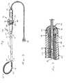
- FIG. 1is a side view of a catheter in accordance with a preferred embodiment of a present invention.
- FIG. 2is a section view of the distal end of the exemplary catheter illustrated in FIG. 1 .
- FIG. 3is a top view of the distal region of the exemplary catheter illustrated in FIG. 1 .
- FIG. 4is a section view of a portion of the distal region of the exemplary catheter illustrated in FIG. 1 .
- FIG. 5is a section view of another portion of the distal region of the exemplary catheter illustrated in FIG. 1 .
- FIG. 6is a top view of the distal region of the exemplary catheter illustrated in FIG. 1 with a portion steered out of the loop plane.
- FIG. 7is an end view of the distal region of the exemplary catheter illustrated in FIG. 1 with a portion steered out of the loop plane.
- FIG. 8is a top view of the distal region of another catheter in accordance with another preferred embodiment of a present invention with a portion steered out of the loop plane.
- FIG. 9is an end view of the exemplary catheter illustrated in FIG. 8 .
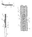
- FIG. 10is a side view of the distal region of a catheter in accordance with still another preferred embodiment of a present invention.
- FIG. 11is a side view of the distal region of a catheter in accordance with yet another preferred embodiment of a present invention with some of the electrodes shown in phantom lines for clarity.
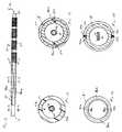
- FIG. 12is a section view taken along line 12 — 12 in FIG. 11 .
- FIG. 13is a section view taken along line 13 — 13 in FIG. 11 .
- FIG. 14is an end view of the distal member in the exemplary catheter illustrated in FIG. 11 .
- FIG. 15is a section view taken along line 15 — 15 in FIG. 11 .
- the present inventionsmay be used within body lumens, chambers or cavities for diagnostic or therapeutic purposes in those instances where access to interior bodily regions is obtained through, for example, the vascular system or alimentary canal and without complex invasive surgical procedures.
- the inventions hereinhave application in the diagnosis and treatment of arrhythmia conditions within the heart.
- the inventions hereinalso have application in the diagnosis or treatment of ailments of the gastrointestinal tract. prostrate, brain, gall bladder, uterus, and other regions of the body.
- the present inventionsare designed to produce intimate tissue contact with target substrates associated with various arrhythmias, namely atrial fibrillation, atrial flutter, and ventricular tachycardia.
- target substrates associated with various arrhythmiasnamely atrial fibrillation, atrial flutter, and ventricular tachycardia.
- embodiments of the present inventionswhich may include diagnostic and/or soft tissue coagulation electrodes, can be used to map tissue and/or create lesions in tissue that cure arrhythmias.
- the present inventionsare discussed primarily in the context of catheter-based probes, the inventions are also adaptable for use with probes other than catheter-based probes.
- the structures disclosed hereinmay be used in conjunction with hand held surgical devices (or “surgical probes”).
- the distal end of a surgical probemay be placed directly in contact with the targeted tissue area by a physician during a surgical procedure, such as open heart surgery.
- accessmay be obtained by way of a thoracotomy, median stemotomy, or thoracostomy.
- Exemplary surgical probesare disclosed in U.S. Pat. No. 6,071,281, which is incorporated herein by reference.
- Surgical probe devices in accordance with the present inventionspreferably include a handle, a relatively short shaft, and one of the distal assemblies described hereafter in the catheter context.
- the length of the shaftis about 4 inches to about 18 inches. This is relatively short in comparison to the portion of a catheter body that is inserted into the patient (typically from 23 to 55 inches in length) and the additional body portion that remains outside the patient.
- the shaftis also relatively stiff. In other words, the shaft is either rigid, malleable, or somewhat flexible. A rigid shaft cannot be bent.
- a malleable shaftis a shaft that can be readily bent by the physician to a desired shape, without springing back when released, so that it will remain in that shape during the surgical procedure.
- the stiffness of a malleable shaftmust be low enough to allow the shaft to be bent, but high enough to resist bending when the forces associated with a surgical procedure are applied to the shaft.
- a somewhat flexible shaftwill bend and spring back when released.
- the force required to bend the shaftmust be substantial.
- a catheter 10 in accordance with a preferred embodiment of a present inventionincludes a hollow, flexible catheter body 12 that is preferably formed from two tubular parts, or members.
- the proximal member 14is relatively long and is attached to a handle 16 , while the distal member 18 , which is relatively short, carries a plurality of spaced electrodes 20 or other operative elements.
- the proximal member 14is typically formed from a biocompatible thermoplastic material, such as a Pebax® material (polyether block emide) and stainless steel braid composite, which has good torque transmission properties.
- an elongate guide coil(not shown) may also be provided within the proximal member 14 .
- the distal member 18is typically formed from a softer, more flexible biocompatible thermoplastic material such as unbraided Pebax® material, polyethylene, or polyurethane.
- the proximal and distal memberswhich are about 5 French to about 9 French in diameter, are preferably either bonded together with an overlapping thermal bond or adhesively bonded together end to end over a sleeve in what is referred to as a “butt bond.”
- the catheter 10is used in combination with a sheath 22 , which preferably has a greater inherent stiffness than the distal region of the catheter 12 (i.e. the distal member 18 , the electrodes 20 and a spline 32 that is discussed below with reference to FIGS. 4 and 5 ).
- the sheath 22should also be lubricious to reduce friction during movement of the catheter body 12 .
- the sheath 14is preferably a Pebax® and stainless steel braid composite. Other materials, such as polytetrafluoroethylene (PTFE), can also be used.
- the wall thickness of the sheath 22is preferably about 0.013 inch, which will not add significantly to the overall thickness of the catheter 10 .
- a handle 24which is preferably in the form of a hemostatic connector that can be used to fix the relative positions of the catheter 12 and sheath 22 , is mounted on the proximal end of the sheath.
- the distal end of the sheath 22is perpendicular to the longitudinal axis of the sheath.
- the distal end of the sheath 22may also be cut at an angle and tapered in a transverse direction relative to the longitudinal axis of the sheath to effect the shape loop formed by the distal region of the catheter 12 .
- a pull wire 26extends from the distal end of the catheter 12 through the sheath 22 in the exemplary embodiment illustrated in FIG. 1 .
- the proximal end of the pull wire 26includes an adjustable stop/handle 28 .
- the pull wire 26is preferably a flexible, inert cable constructed from strands of metal wire material, such as Nickel Titanium (commercially available under the trade name Nitinol®) or 17-7 stainless steel, that is about 0.012 to 0.018 inch in diameter.
- the pull wire 26may be formed from a flexible, inert stranded or molded plastic material.
- the pull wire 26is also preferably round in cross-section, although other cross-sectional configurations can be used.
- the physiciandeploys a loop structure 30 by advancing the catheter body 12 through the sheath 22 .
- the physiciancan pull on the wire 26 to decrease the exposed length of the pull wire beyond the distal end of the sheath 22 .
- Further adjustments to the loopmay be made by advancing or retracting the catheter body 12 within the sheath 22 or by putting tension on the pull wire 24 .
- a portion of the loop structure 30my be bent out of the loop plane. This aspect of the invention is discussed in greater detail below with reference to FIGS. 5-9 .
- the loop structure 30can be rotated by rotating the catheter body 12 with its handle 16 .
- the exemplary catheter body 12also includes a flexible spline (or “core wire”) 32 .
- the flexible spline 32is preferably a wire having a diameter of approximately 0.023 inch that is positioned inside of and passes within the length of the catheter body 12 .
- the flexible spline 32is fixedly secured to the handle 16 at the proximal end of the catheter body 12 and to a tip member 34 in the manner described below.
- the tip member 34is in turn secured to the distal end of the catheter body 12 with adhesive.
- the flexible spline 32is made from resilient, inert wire, such as Nitinol® material or 17-7 stainless steel. Resilient injection molded plastic can also be used.
- the exemplary spline 32is round in cross section, although other cross sectional configurations can be used.
- the flexible spline 32may, if desired, also have a preset curvature accomplished by thermally presetting the spline at 500° C. for 8 minutes. The super-elastic properties of the material should, however, be maintained.
- the flexible spline 32includes a flattened portion 36 , which is preferably adjacent to (i.e. either just proximal to, just distal to, or aligned with) the proximal end of the distal member 18 , that allows this portion of the flexible spline to be bent with less force than would otherwise be required.
- the flattened portion 36also causes the distal member 18 to bend, and the loop structure 30 to be formed, in a flat loop plane (note the side view in FIG. 1 and the top view in FIG. 3 ).
- the thickness of the flattened portion 36would be about 0.018 inch and the length would be about 1.75 inches.
- the flexible spline 32may also be used to anchor the pull wire 26 . As illustrated for example in FIG. 2 , the distal end 38 of the flexible spline 32 is fixedly engaged in an in-line manner to the end 40 of the pull wire 26 with a stainless steel crimp tube 42 .
- the in-line connection of the flexible spline 32 and pull wire 26allows for a reduction in the overall diameter of distal portion of the catheter body 12 . This provides a significant clinical advantage over devices having side by side pull wire connections which create a larger diameter device.
- the pull wire 26passes through a pull wire bore 44 in the catheter tip member 24 and through a bore 46 in the distal end of the crimp tube 42 .
- the tip member 34is preferably formed from platinum-iridium ( 90 / 10 ) and is fixedly engaged with, for example, silver solder, adhesive or spot welding, to the distal end of crimp tube 42 .
- the flexible spline 32is preferably electrically insulated with a thin walled polyester heat shrink tube 48 that extends beyond the proximal end of the crimp tube 42 .
- Other pull wire configurations, other methods of attaching the pull wire to the catheter body, and methods of reducing stress on the pull wireare disclosed in U.S. Pat. No. 6,048,329, which is incorporated herein by reference.
- the exemplary catheter 10 presentalso includes a loop deflection system that allows the physician to steer a portion 50 of the loop structure 30 out of the loop plane in the manner illustrated in FIGS. 6 and 7 .
- the steering capabilitymay, for example, be provided through the use of one or more steering wires.
- the exemplary catheter 10includes a pair of steering wires 52 a and 52 b which pass through the heat shrink tube 48 and are secured to the flexible spline 32 with a crimp joint, solder, adhesive or other suitable instrumentalities.
- Steering wires 52 a and 52 bextend proximally to the exemplary handle 16 , which includes handle body 54 and a steering assembly 56 that consists of a cam wheel 58 and a lever 60 .
- the proximal ends of each of the steering wires 52 a and 52 bare secured to a cam wheel 58 .
- the steering of portion 50may be facilitated by forming a second flattened portion 62 in the spline 32 just proximally of the point at which the steering wires 52 a and 52 b are attached to the spline.
- the second flattened portion 62which is rotated 90 degrees relative to the flattened portion 36 , facilitates the steering of portion 50 by giving the bend directionality and creating a live hinge.
- the thickness of the second flattened portion 62would be about 0.010 inch and the length would be about 0.50 inch.
- FIGS. 8 and 9Steerable portion 50 ′ is larger than the steerable portion 50 illustrated in FIGS. 6 and 7 because the second flattened portion (not shown) in the embodiment illustrated in FIG. 8 and 9 is longer than the second flattened portion 62 illustrated in FIG. 5 .
- a suitable length for the second flattened portion 62 in an embodiment where the flexible spline 32 has a diameter of approximately 0.023 inchwould be about 1.5 inches.
- the present inventionsare also applicable to loop catheters in which the distal portion of catheter body is connected to the distal portion of the sheath.
- the exemplary catheter 64does not include a pull wire and instead is used in combination with a sheath 66 which has a distal member 68 that is connected to the distal end of the catheter 64 .
- a slotis formed in the distal portion of the sheath 66 and the remnant 70 forms a flexible joint.
- a stiffening element 72may also be provided.
- the loop 74is formed when the catheter 64 is urged distally relative to the sheath 66 , thereby causing the distal portion of the catheter to bulge outwardly in the manner illustrated in FIG. 10 .
- exemplary catheter 64also includes the loop steering elements described above.
- loop steering elements described abovemay also be used in other loop catheters where the distal portion of catheter body is connected to the distal portion of the sheath.
- One exampleis a catheter wherein the distal end of the catheter body is connected to the distal end of a sheath by a short wire. This and other examples of such loop catheters are disclosed in U.S. Pat. No. 6,071,274, which is incorporated herein by reference.
- the steering wires 52 a and 52 bmay be secured at respective points on the exterior of the catheter and then directed to respective points that are on the opposite side of the catheter.
- Such an arrangementprovides more steering torque than would be realized if the steering wires were simply allowed to extend proximally from their attachment point in the manner illustrated in FIG. 5 because the present arrangement increases the effective lever length.
- This arrangementis also applicable to steerable catheters that are not adapted to be bent into loops as well as catheters with a single steering wire, whether adapted to be bent into a loop or not.
- the exemplary catheter 84 illustrated in FIGS. 11-15is in many respects identical to the catheter 10 illustrated in FIGS. 1-7 .
- the steering wires 52 a and 52 bare not secured to the spline 32 .
- the steering wires 52 a and 52 bare instead directed through steering wire lumens 86 a and 86 b which are formed in the distal member 18 ′.
- the steering wire lumens 86 a and 86 bwhich include respective inlets 88 a and 88 b and outlets 90 a and 90 b , each wind half way (i.e. 180 degrees) around the distal member 18 ′.
- the rotational position change measured as a function of longitudinal position changeis preferably constant from one end of the steering wire lumens 86 a and 86 b to the other.
- the inlets 88 a and 88 b and outlets 90 a and 90 bare also perpendicular to (i.e. offset 90 degrees from) the flattened surfaces of the second flattened portion 62 .
- the exemplary distal member 18 ′could be formed by a multi-lumen extrusion process so if desired, the preferred process is a molding process.
- core pins formed from flexible metal tubescould be used to form the steering wire lumens 86 a and 86 b.
- the distal ends of the steering wires 52 a and 52 bextend outwardly through the outlets 90 a and 90 b and are secured to one of the electrodes 20 by, for example, welding or soldering.
- the steering wires 52 a and 52 bcould be secured to a support ring (not shown) mounted on the exterior of the distal member 18 ′.
- a guide coil (not shown), or other tubular member though which the steering wires 52 a and 52 b would pass,may be positioned within the steering wire lumens 86 a and 86 b to provide additional column strength.
- the steering wire lumens 86 a and 86 bwould be eliminated and replaced by channels formed in the outer surface of the distal member 18 ′.
- the channelswould extend around the distal member in the same manner as the steering wire lumens 86 a and 86 b and the inlets 88 a and 88 b would simply extend through the wall of the distal member 18 ′ to the proximal ends of the channels.
- Guide coils, or other tubular members through which the steering wires 52 a and 52 b pass,would be positioned within the channels.
- the electrodes 20would be placed over the channels and guide coils.
- the operative elementsare a plurality of spaced electrodes 20 .
- other operative elementssuch as lumens for chemical ablation, laser arrays, ultrasonic transducers, microwave electrodes, and ohmically heated hot wires, and such devices may be substituted for the electrodes.
- the spaced electrodes 20are preferably in the form of wound, spiral coils.
- the coilsare made of electrically conducting material, like copper alloy, platinum, or stainless steel, or compositions such as drawn-filled tubing (e.g. a copper core with a platinum jacket).
- the electrically conducting material of the coilscan be further coated with platinum-iridium or gold to improve its conduction properties and biocompatibility.
- a preferred coil electrodeis disclosed in U.S. Pat.
- the electrodes 20are electrically coupled to individual wires (not shown) to conduct coagulating energy to them.
- the wiresare passed in conventional fashion through a lumen extending through the associated catheter body into a PC board in the catheter handle, where they are electrically coupled to a connector 76 that is received in a port on the handle.
- a connector 78may be plugged into a source of RF coagulation energy and/or an electrophysiology recording system for mapping.
- the electrodesmay be in the form of solid rings of conductive material, like platinum, or can comprise a conductive material, like platinum-iridium or gold, coated upon the device using conventional coating techniques or an ion beam assisted deposition (IBAD) process. For better adherence, an undercoating of nickel or titanium can be applied.
- the electrodescan also be in the form of helical ribbons.
- the electrodescan also be formed with a conductive ink compound that is pad printed onto a non-conductive tubular body.
- a preferred conductive ink compoundis a silver-based flexible adhesive conductive ink (polyurethane binder), however other metal-based adhesive conductive inks such as platinum-based, gold-based, copper-based, etc., may also be used to form electrodes. Such inks are more flexible than epoxy-based inks.
- the flexible electrodes 20are preferably about 4 mm to about 20 mm in length.
- the electrodesare 12.5 mm in length with 1 mm to 3 mm spacing, which will result in the creation of continuous lesion patterns in tissue when coagulation energy is applied simultaneously to adjacent electrodes.
- the length of the each electrodecan vary from about 2 mm to about 10 mm. Using multiple rigid electrodes longer than about 10 mm each adversely effects the overall flexibility of the device, while electrodes having lengths of less than about 2 mm do not consistently form the desired continuous lesion patterns.
- the portion of the electrodes 20 that are not intended to contact tissue (and be exposed to the blood pool)may be masked through a variety of techniques with a material that is preferably electrically and thermally insulating. This prevents the transmission of coagulation energy directly into the blood pool and directs the energy directly toward and into the tissue.
- a layer of UV adhesive(or another adhesive) may be painted on preselected portions of the electrodes to insulate the portions of the electrodes not intended to contact tissue.
- Deposition techniquesmay also be implemented to position a conductive surface only on those portions of the assembly intended to contact tissue.
- a coatingmay be formed by dipping the electrodes in PTFE material.
- the electrodesmay be operated in a uni-polar mode, in which the soft tissue coagulation energy emitted by the electrodes is returned through an indifferent patch electrode (not shown) externally attached to the skin of the patient.
- the electrodesmay be operated in a bi-polar mode, in which energy emitted by one or more electrodes is returned through other electrodes.
- the amount of power required to coagulate tissueranges from 5 to 150 w.
- a plurality of temperature sensors 80may be located on, under, abutting the longitudinal end edges of, or in between, the electrodes 20 .
- the temperature sensors 80are located at the longitudinal edges of the electrodes 20 .
- a reference thermocouple 82may also be provided.
- signals from the temperature sensorsare transmitted to the source of coagulation energy by way of wires (not shown) that are also connected to the aforementioned PC board in the catheter handle.
- wiresnot shown
- Suitable temperature sensors and controllers which control power to electrodes based on a sensed temperatureare disclosed in U.S. Pat. Nos. 5,456,682, 5,582,609 and 5,755,715.
- the temperature sensors 80may be located on two sides of catheter, as illustrated in FIG. 4 .
- the temperature sensorsmay all be located on the same side of the catheter, as illustrated in FIG. 10 .
- the temperature sensorswill be preferably located within a linear channel (not shown) that is formed in the distal member 18 . The linear channel insures that the temperature sensors will directly face the tissue and be arranged in linear fashion. Such an arrangement results in more accurate temperature readings which, in turn, results in better temperature control.
- the actual tissue temperaturewill more accurately correspond to the temperature set by the physician on the power control device, thereby providing the physician with better control of the lesion creation process and reducing the likelihood that embolic materials will be formed.
- a channelmay be employed in conjunction with any of the electrode (or other operative element) supporting structures disclosed herein.
- the electrodes 20 and temperature sensors 80can include a porous material coating, which transmits coagulation energy through an electrified ionic medium.
- electrodes and temperature sensorsmay be coated with regenerated cellulose, hydrogel or plastic having electrically conductive components.
- the coatingacts as a mechanical barrier between the surgical device components, such as electrodes, preventing ingress of blood cells, infectious agents, such as viruses and bacteria, and large biological molecules such as proteins, while providing electrical contact to the human body.
- the regenerated cellulose coatingalso acts as a biocompatible barrier between the device components and the human body, whereby the components can now be made from materials that are somewhat toxic (such as silver or copper).
Landscapes
- Health & Medical Sciences (AREA)
- Surgery (AREA)
- Life Sciences & Earth Sciences (AREA)
- Engineering & Computer Science (AREA)
- Molecular Biology (AREA)
- Public Health (AREA)
- Otolaryngology (AREA)
- Plasma & Fusion (AREA)
- Physics & Mathematics (AREA)
- Biomedical Technology (AREA)
- Heart & Thoracic Surgery (AREA)
- Medical Informatics (AREA)
- Cardiology (AREA)
- Animal Behavior & Ethology (AREA)
- General Health & Medical Sciences (AREA)
- Nuclear Medicine, Radiotherapy & Molecular Imaging (AREA)
- Veterinary Medicine (AREA)
- Surgical Instruments (AREA)
- Media Introduction/Drainage Providing Device (AREA)
- Electrotherapy Devices (AREA)
- Measurement Of The Respiration, Hearing Ability, Form, And Blood Characteristics Of Living Organisms (AREA)
- Power Steering Mechanism (AREA)
- Steering Control In Accordance With Driving Conditions (AREA)
- Investigating Or Analyzing Materials By The Use Of Ultrasonic Waves (AREA)
- Ultra Sonic Daignosis Equipment (AREA)
- Apparatus For Radiation Diagnosis (AREA)
Abstract
Description
Claims (21)
Priority Applications (13)
| Application Number | Priority Date | Filing Date | Title |
|---|---|---|---|
| US09/709,087US6916306B1 (en) | 2000-11-10 | 2000-11-10 | Steerable loop structures for supporting diagnostic and therapeutic elements in contact with body tissue |
| AT01993425TATE284172T1 (en) | 2000-11-10 | 2001-10-23 | CONTROLLABLE LOOP STRUCTURES TO SUPPORT DIAGNOSTIC AND THERAPEUTIC ELEMENTS IN CONTACT WITH BODY TISSUE |
| EP01993425AEP1331893B1 (en) | 2000-11-10 | 2001-10-23 | Steerable loop structures for supporting diagnostic and therapeutic elements in contact with body tissue |
| DE60107711TDE60107711T2 (en) | 2000-11-10 | 2001-10-23 | CONTROLLABLE STRUCTURES FOR SUPPORTING DIAGNOSTIC AND THERAPEUTIC ELEMENTS IN CONTACT WITH BODY TISSUE |
| AU2002220651AAU2002220651A1 (en) | 2000-11-10 | 2001-10-23 | Steerable loop structure |
| JP2002540642AJP4167059B2 (en) | 2000-11-10 | 2001-10-23 | Steerable loop structure |
| EP04028757AEP1510180B1 (en) | 2000-11-10 | 2001-10-23 | Steerable loop structure |
| ES01993425TES2232678T3 (en) | 2000-11-10 | 2001-10-23 | LOOP STRUCTURES WITH ADDRESS CAPACITY, FOR SUPPORT OF THERAPEUTIC AND DIAGNOSTIC ELEMENTS IN CONTACT WITH BODY FABRICS. |
| PCT/EP2001/012243WO2002038052A2 (en) | 2000-11-10 | 2001-10-23 | Steerable loop structure |
| DE60127876TDE60127876T2 (en) | 2000-11-10 | 2001-10-23 | Controllable loop structure |
| AT04028757TATE359034T1 (en) | 2000-11-10 | 2001-10-23 | CONTROLLER LOOP STRUCTURE |
| CA002428314ACA2428314A1 (en) | 2000-11-10 | 2001-10-23 | Steerable loop structure |
| US11/130,857US7182764B2 (en) | 2000-11-10 | 2005-05-17 | Steerable loop structures for supporting diagnostic and therapeutic elements in contact with body tissue |
Applications Claiming Priority (1)
| Application Number | Priority Date | Filing Date | Title |
|---|---|---|---|
| US09/709,087US6916306B1 (en) | 2000-11-10 | 2000-11-10 | Steerable loop structures for supporting diagnostic and therapeutic elements in contact with body tissue |
Related Child Applications (1)
| Application Number | Title | Priority Date | Filing Date |
|---|---|---|---|
| US11/130,857DivisionUS7182764B2 (en) | 2000-11-10 | 2005-05-17 | Steerable loop structures for supporting diagnostic and therapeutic elements in contact with body tissue |
Publications (1)
| Publication Number | Publication Date |
|---|---|
| US6916306B1true US6916306B1 (en) | 2005-07-12 |
Family
ID=24848428
Family Applications (2)
| Application Number | Title | Priority Date | Filing Date |
|---|---|---|---|
| US09/709,087Expired - LifetimeUS6916306B1 (en) | 2000-11-10 | 2000-11-10 | Steerable loop structures for supporting diagnostic and therapeutic elements in contact with body tissue |
| US11/130,857Expired - LifetimeUS7182764B2 (en) | 2000-11-10 | 2005-05-17 | Steerable loop structures for supporting diagnostic and therapeutic elements in contact with body tissue |
Family Applications After (1)
| Application Number | Title | Priority Date | Filing Date |
|---|---|---|---|
| US11/130,857Expired - LifetimeUS7182764B2 (en) | 2000-11-10 | 2005-05-17 | Steerable loop structures for supporting diagnostic and therapeutic elements in contact with body tissue |
Country Status (9)
| Country | Link |
|---|---|
| US (2) | US6916306B1 (en) |
| EP (2) | EP1510180B1 (en) |
| JP (1) | JP4167059B2 (en) |
| AT (2) | ATE359034T1 (en) |
| AU (1) | AU2002220651A1 (en) |
| CA (1) | CA2428314A1 (en) |
| DE (2) | DE60107711T2 (en) |
| ES (1) | ES2232678T3 (en) |
| WO (1) | WO2002038052A2 (en) |
Cited By (54)
| Publication number | Priority date | Publication date | Assignee | Title |
|---|---|---|---|---|
| US20050215992A1 (en)* | 2000-11-10 | 2005-09-29 | Jenkins Thomas R | Steerable loop structures for supporting diagnostic and therapeutic elements in contact with body tissue |
| US20050256452A1 (en)* | 2002-11-15 | 2005-11-17 | Demarchi Thomas | Steerable vascular sheath |
| US20060064054A1 (en)* | 2002-11-15 | 2006-03-23 | Applied Medical Resources Corporation | Longitudinal sheath enforcement |
| US20060235304A1 (en)* | 2005-04-15 | 2006-10-19 | Harhen Edward P | Connectorized probe for transesophageal echocardiography |
| US20070215268A1 (en)* | 2002-11-15 | 2007-09-20 | Applied Medical Resources Corporation | Method of making medical tubing having variable characteristics using thermal winding |
| US20070260225A1 (en)* | 2002-11-15 | 2007-11-08 | Applied Medical Resources Corporation | Steerable sheath actuator |
| US20070282167A1 (en)* | 2006-05-19 | 2007-12-06 | Michael Barenboym | Control mechanism for steerable medical device |
| US20070277921A1 (en)* | 2002-11-15 | 2007-12-06 | Applied Medical Resources Corporation | Steerable kink-resistant sheath |
| US20080188850A1 (en)* | 2007-02-06 | 2008-08-07 | Microcube, Llc | Delivery system for delivering a medical device to a location within a patient's body |
| US20080195088A1 (en)* | 1999-07-14 | 2008-08-14 | Cardiofocus, Inc. | Method and device for cardiac tissue ablation |
| US7811291B2 (en) | 2007-11-16 | 2010-10-12 | Osseon Therapeutics, Inc. | Closed vertebroplasty bone cement injection system |
| US7850685B2 (en) | 2005-06-20 | 2010-12-14 | Medtronic Ablation Frontiers Llc | Ablation catheter |
| US20110005661A1 (en)* | 2004-01-28 | 2011-01-13 | Applied Medical Resources Corporation | Medical Tubing Having Variable Characteristics and Method of Making Same |
| US7935108B2 (en)* | 1999-07-14 | 2011-05-03 | Cardiofocus, Inc. | Deflectable sheath catheters |
| US20110160785A1 (en)* | 2008-09-11 | 2011-06-30 | Kenji Mori | Defibrillation catheter |
| US7988735B2 (en)* | 2005-06-15 | 2011-08-02 | Matthew Yurek | Mechanical apparatus and method for delivering materials into the inter-vertebral body space for nucleus replacement |
| US8241272B2 (en) | 1994-09-09 | 2012-08-14 | Cardiofocus, Inc. | Methods for ablation with radiant energy |
| US8273084B2 (en) | 2004-11-24 | 2012-09-25 | Medtronic Ablation Frontiers Llc | Atrial ablation catheter and method of use |
| US8486063B2 (en) | 2004-10-14 | 2013-07-16 | Medtronic Ablation Frontiers Llc | Ablation catheter |
| AU2010228558B2 (en)* | 2009-03-23 | 2013-09-19 | Japan Lifeline Co., Ltd. | Intracardiac defibrillation catheter system |
| US8540704B2 (en) | 1999-07-14 | 2013-09-24 | Cardiofocus, Inc. | Guided cardiac ablation catheters |
| US8617152B2 (en) | 2004-11-15 | 2013-12-31 | Medtronic Ablation Frontiers Llc | Ablation system with feedback |
| US8641704B2 (en) | 2007-05-11 | 2014-02-04 | Medtronic Ablation Frontiers Llc | Ablation therapy system and method for treating continuous atrial fibrillation |
| US8657814B2 (en) | 2005-08-22 | 2014-02-25 | Medtronic Ablation Frontiers Llc | User interface for tissue ablation system |
| US8696653B2 (en) | 2009-10-02 | 2014-04-15 | Cardiofocus, Inc. | Cardiac ablation system with pulsed aiming light |
| US8702688B2 (en) | 2009-10-06 | 2014-04-22 | Cardiofocus, Inc. | Cardiac ablation image analysis system and process |
| US8827981B2 (en) | 2007-11-16 | 2014-09-09 | Osseon Llc | Steerable vertebroplasty system with cavity creation element |
| US8834461B2 (en) | 2005-07-11 | 2014-09-16 | Medtronic Ablation Frontiers Llc | Low power tissue ablation system |
| US20140275757A1 (en)* | 2013-03-15 | 2014-09-18 | Mitralign, Inc. | Translation Catheters, Systems, and Methods of Use Thereof |
| US8900219B2 (en) | 1999-07-14 | 2014-12-02 | Cardiofocus, Inc. | System and method for visualizing tissue during ablation procedures |
| US20150045696A1 (en)* | 2013-08-09 | 2015-02-12 | Oscor Inc. | Steerable dilator |
| US8992421B2 (en) | 2010-10-22 | 2015-03-31 | Medrobotics Corporation | Highly articulated robotic probes and methods of production and use of such probes |
| US9005194B2 (en) | 2004-11-24 | 2015-04-14 | Medtronic Ablation Frontiers Llc | Atrial ablation catheter adapted for treatment of septal wall arrhythmogenic foci and method of use |
| US9033961B2 (en) | 1999-07-14 | 2015-05-19 | Cardiofocus, Inc. | Cardiac ablation catheters for forming overlapping lesions |
| US9364955B2 (en) | 2011-12-21 | 2016-06-14 | Medrobotics Corporation | Stabilizing apparatus for highly articulated probes with link arrangement, methods of formation thereof, and methods of use thereof |
| US9510885B2 (en) | 2007-11-16 | 2016-12-06 | Osseon Llc | Steerable and curvable cavity creation system |
| US9572628B2 (en) | 2011-09-13 | 2017-02-21 | Medrobotics Corporation | Highly articulated probes with anti-twist link arrangement, methods of formation thereof, and methods of performing medical procedures |
| US9649163B2 (en) | 2010-11-11 | 2017-05-16 | Medrobotics Corporation | Introduction devices for highly articulated robotic probes and methods of production and use of such probes |
| US9901410B2 (en) | 2010-07-28 | 2018-02-27 | Medrobotics Corporation | Surgical positioning and support system |
| US9907570B2 (en) | 2013-08-23 | 2018-03-06 | Oscor Inc. | Steerable medical devices |
| US10154888B2 (en) | 2014-12-03 | 2018-12-18 | Cardiofocus, Inc. | System and method for visual confirmation of pulmonary vein isolation during abalation procedures |
| US10463380B2 (en) | 2016-12-09 | 2019-11-05 | Dfine, Inc. | Medical devices for treating hard tissues and related methods |
| US10478241B2 (en) | 2016-10-27 | 2019-11-19 | Merit Medical Systems, Inc. | Articulating osteotome with cement delivery channel |
| US10624652B2 (en) | 2010-04-29 | 2020-04-21 | Dfine, Inc. | System for use in treatment of vertebral fractures |
| US10660656B2 (en) | 2017-01-06 | 2020-05-26 | Dfine, Inc. | Osteotome with a distal portion for simultaneous advancement and articulation |
| US10695073B2 (en) | 2017-08-22 | 2020-06-30 | Arthrex, Inc. | Control system for retrograde drill medical device |
| US10918373B2 (en) | 2013-08-31 | 2021-02-16 | Edwards Lifesciences Corporation | Devices and methods for locating and implanting tissue anchors at mitral valve commissure |
| US10932848B2 (en) | 2007-02-06 | 2021-03-02 | Microcube, Llc | Delivery system for delivering a medical device to a location within a patient's body |
| US11026744B2 (en) | 2016-11-28 | 2021-06-08 | Dfine, Inc. | Tumor ablation devices and related methods |
| US11197681B2 (en) | 2009-05-20 | 2021-12-14 | Merit Medical Systems, Inc. | Steerable curvable vertebroplasty drill |
| US11246476B2 (en) | 2014-04-28 | 2022-02-15 | Cardiofocus, Inc. | Method for visualizing tissue with an ICG dye composition during ablation procedures |
| US11510723B2 (en) | 2018-11-08 | 2022-11-29 | Dfine, Inc. | Tumor ablation device and related systems and methods |
| US11660190B2 (en) | 2007-03-13 | 2023-05-30 | Edwards Lifesciences Corporation | Tissue anchors, systems and methods, and devices |
| US11986229B2 (en) | 2019-09-18 | 2024-05-21 | Merit Medical Systems, Inc. | Osteotome with inflatable portion and multiwire articulation |
Families Citing this family (28)
| Publication number | Priority date | Publication date | Assignee | Title |
|---|---|---|---|---|
| US6302880B1 (en)* | 1996-04-08 | 2001-10-16 | Cardima, Inc. | Linear ablation assembly |
| US7226446B1 (en) | 1999-05-04 | 2007-06-05 | Dinesh Mody | Surgical microwave ablation assembly |
| US6277113B1 (en) | 1999-05-28 | 2001-08-21 | Afx, Inc. | Monopole tip for ablation catheter and methods for using same |
| US7033352B1 (en) | 2000-01-18 | 2006-04-25 | Afx, Inc. | Flexible ablation instrument |
| US20020087151A1 (en) | 2000-12-29 | 2002-07-04 | Afx, Inc. | Tissue ablation apparatus with a sliding ablation instrument and method |
| US6893436B2 (en)* | 2002-01-03 | 2005-05-17 | Afx, Inc. | Ablation instrument having a flexible distal portion |
| US7192427B2 (en) | 2002-02-19 | 2007-03-20 | Afx, Inc. | Apparatus and method for assessing transmurality of a tissue ablation |
| US20040199052A1 (en) | 2003-04-01 | 2004-10-07 | Scimed Life Systems, Inc. | Endoscopic imaging system |
| US7147635B2 (en) | 2004-01-29 | 2006-12-12 | Ethicon, Inc. | Bipolar electrosurgical snare |
| US7288088B2 (en) | 2004-05-10 | 2007-10-30 | Boston Scientific Scimed, Inc. | Clamp based low temperature lesion formation apparatus, systems and methods |
| US7582083B2 (en) | 2004-05-10 | 2009-09-01 | Boston Scientific Scimed, Inc. | Probe based low temperature lesion formation apparatus, systems and methods |
| US7291142B2 (en) | 2004-05-10 | 2007-11-06 | Boston Scientific Scimed, Inc. | Low temperature lesion formation apparatus, systems and methods |
| EP1866019B1 (en)* | 2005-02-22 | 2017-10-25 | Cardiofocus, Inc. | Deflectable sheath catheters |
| KR100778142B1 (en)* | 2005-11-09 | 2007-11-29 | 황창모 | Radio frequency ablation electrode for selected tissue removal |
| FR2896698B1 (en)* | 2006-02-02 | 2008-09-19 | Vygon Sa | NEUROSTIMULATION CATHETER AND ITS BASE |
| WO2009079545A1 (en)* | 2007-12-19 | 2009-06-25 | Boston Scientific Scimed, Inc. | Structure for use as part of a medical device |
| WO2009094511A1 (en)* | 2008-01-24 | 2009-07-30 | Boston Scientific Scimed, Inc. | Structure for use as part of a medical device |
| US20090240109A1 (en)* | 2008-03-24 | 2009-09-24 | Boston Scientific Scimed, Inc. | Flexible endoscope with core member |
| US10695126B2 (en) | 2008-10-06 | 2020-06-30 | Santa Anna Tech Llc | Catheter with a double balloon structure to generate and apply a heated ablative zone to tissue |
| US20110046657A1 (en)* | 2009-08-20 | 2011-02-24 | Boston Scientific Scimed, Inc. | Embolic Coil Introducer Catheter Locking Mechanisms |
| DE102011085721A1 (en)* | 2011-11-03 | 2013-05-08 | Günter Farin | HF surgical resection instrument with a resection loop for removal of pathological tissue |
| EP2881057A1 (en)* | 2013-12-05 | 2015-06-10 | Region Nordjylland | Apparatus for creating linear lesions in body tissue within a body vessel |
| US11344365B2 (en) | 2016-01-05 | 2022-05-31 | Cardiofocus, Inc. | Ablation system with automated sweeping ablation energy element |
| US12364537B2 (en) | 2016-05-02 | 2025-07-22 | Santa Anna Tech Llc | Catheter with a double balloon structure to generate and apply a heated ablative zone to tissue |
| US11331140B2 (en) | 2016-05-19 | 2022-05-17 | Aqua Heart, Inc. | Heated vapor ablation systems and methods for treating cardiac conditions |
| USD851245S1 (en) | 2017-04-14 | 2019-06-11 | Cardiofocus, Inc. | Compliant balloon |
| EP3740147B1 (en) | 2018-01-15 | 2024-03-27 | Cardiofocus, Inc. | Ablation system with automated ablation energy element |
| JP7568257B2 (en)* | 2020-04-30 | 2024-10-16 | ジェイソル・メディカル株式会社 | Catheter for measuring cardiac potential |
Citations (70)
| Publication number | Priority date | Publication date | Assignee | Title |
|---|---|---|---|---|
| US1207479A (en) | 1915-03-05 | 1916-12-05 | Holger Bisgaard | Self-retaining gatheter. |
| US4033331A (en) | 1975-07-17 | 1977-07-05 | Guss Stephen B | Cardiac catheter and method of using same |
| US4181131A (en) | 1977-02-28 | 1980-01-01 | Olympus Optical Co., Ltd. | High frequency electrosurgical instrument for cutting human body cavity structures |
| US4245624A (en) | 1977-01-20 | 1981-01-20 | Olympus Optical Co., Ltd. | Endoscope with flexible tip control |
| EP0238106A1 (en) | 1986-02-11 | 1987-09-23 | Louis Johannes Karel Jozef Reytenbagh | Catheter provided with positioning means |
| US4753223A (en) | 1986-11-07 | 1988-06-28 | Bremer Paul W | System for controlling shape and direction of a catheter, cannula, electrode, endoscope or similar article |
| US4826087A (en) | 1985-02-12 | 1989-05-02 | David Chinery | Manipulative device |
| DE3920707A1 (en) | 1989-06-24 | 1991-01-10 | Foerster Ernst | catheter with flexible end piece - which can be deflected by control wire in guide on side of catheter body |
| US5041085A (en) | 1990-02-26 | 1991-08-20 | Cook Incorporated | Percutaneous lockable sleeve catheter |
| US5098412A (en) | 1989-11-04 | 1992-03-24 | Shiu Man F | Support system for catheter |
| US5156151A (en) | 1991-02-15 | 1992-10-20 | Cardiac Pathways Corporation | Endocardial mapping and ablation system and catheter probe |
| US5263493A (en) | 1992-02-24 | 1993-11-23 | Boaz Avitall | Deflectable loop electrode array mapping and ablation catheter for cardiac chambers |
| US5273535A (en) | 1991-11-08 | 1993-12-28 | Ep Technologies, Inc. | Catheter with electrode tip having asymmetric left and right curve configurations |
| US5306245A (en) | 1993-02-23 | 1994-04-26 | Advanced Surgical Inc. | Articulating device |
| US5368592A (en) | 1992-04-13 | 1994-11-29 | Ep Technologies, Inc. | Articulated systems for cardiac ablation |
| US5399165A (en) | 1993-01-28 | 1995-03-21 | Cook Incorporated | Lockable connector, a drainage catheter utilizing the connector, and method of use |
| US5415656A (en) | 1993-09-28 | 1995-05-16 | American Medical Systems, Inc. | Electrosurgical apparatus |
| US5437665A (en) | 1993-10-12 | 1995-08-01 | Munro; Malcolm G. | Electrosurgical loop electrode instrument for laparoscopic surgery |
| US5439006A (en) | 1991-08-28 | 1995-08-08 | Medtronic, Inc. | Steerable stylet and manipulative handle assembly |
| US5482037A (en) | 1993-01-18 | 1996-01-09 | X-Trode S.R.L. | Electrode catheter for mapping and operating on cardiac cavities |
| US5487385A (en) | 1993-12-03 | 1996-01-30 | Avitall; Boaz | Atrial mapping and ablation catheter system |
| US5549661A (en) | 1993-10-15 | 1996-08-27 | Ep Technologies, Inc. | Systems and methods for creating complex lesion patterns in body tissue |
| EP0737487A2 (en) | 1992-04-10 | 1996-10-16 | Cardiorhythm | Steerable electrode catheter |
| US5571088A (en) | 1993-07-01 | 1996-11-05 | Boston Scientific Corporation | Ablation catheters |
| US5582609A (en) | 1993-10-14 | 1996-12-10 | Ep Technologies, Inc. | Systems and methods for forming large lesions in body tissue using curvilinear electrode elements |
| US5637090A (en) | 1993-10-15 | 1997-06-10 | Ep Technologies, Inc. | Multiple electrode element for mapping and ablating heart tissue |
| US5656029A (en) | 1992-12-01 | 1997-08-12 | Cardiac Pathways Corporation | Steerable catheter with adjustable bend location and/or radius and method |
| US5702438A (en) | 1995-06-08 | 1997-12-30 | Avitall; Boaz | Expandable recording and ablation catheter system |
| US5702368A (en) | 1991-07-16 | 1997-12-30 | Heartport, Inc. | System for cardiac procedures |
| US5709224A (en) | 1995-06-07 | 1998-01-20 | Radiotherapeutics Corporation | Method and device for permanent vessel occlusion |
| US5730127A (en) | 1993-12-03 | 1998-03-24 | Avitall; Boaz | Mapping and ablation catheter system |
| US5738683A (en) | 1994-07-16 | 1998-04-14 | Osypka; Peter | Mapping and ablation catheter |
| WO1998026724A1 (en) | 1996-12-19 | 1998-06-25 | Ep Technologies, Inc. | Branched structures for supporting multiple electrode elements |
| US5782239A (en) | 1992-06-30 | 1998-07-21 | Cordis Webster, Inc. | Unique electrode configurations for cardiovascular electrode catheter with built-in deflection method and central puller wire |
| US5782899A (en) | 1992-06-05 | 1998-07-21 | Cardiac Pathways Corporation | Endocardial mapping and ablation system utilizing a separately controlled ablation catheter and method |
| US5800482A (en) | 1996-03-06 | 1998-09-01 | Cardiac Pathways Corporation | Apparatus and method for linear lesion ablation |
| US5800484A (en) | 1995-08-15 | 1998-09-01 | Rita Medical Systems, Inc. | Multiple antenna ablation apparatus with expanded electrodes |
| EP0868922A2 (en) | 1997-04-02 | 1998-10-07 | Medtronic, Inc. | Enhanced contact steerable bowing electrode catheter assembly |
| US5820591A (en) | 1990-02-02 | 1998-10-13 | E. P. Technologies, Inc. | Assemblies for creating compound curves in distal catheter regions |
| US5836947A (en) | 1994-10-07 | 1998-11-17 | Ep Technologies, Inc. | Flexible structures having movable splines for supporting electrode elements |
| US5863291A (en) | 1996-04-08 | 1999-01-26 | Cardima, Inc. | Linear ablation assembly |
| US5865800A (en) | 1993-08-19 | 1999-02-02 | Boston Scientific Corporation | Deflectable catheter |
| WO1999005971A1 (en) | 1997-08-01 | 1999-02-11 | Cardiac Pathways Corporation | System for electrode localization using ultrasound |
| US5871523A (en) | 1993-10-15 | 1999-02-16 | Ep Technologies, Inc. | Helically wound radio-frequency emitting electrodes for creating lesions in body tissue |
| US5882333A (en) | 1994-05-13 | 1999-03-16 | Cardima, Inc. | Catheter with deflectable distal section |
| US5895417A (en) | 1996-03-06 | 1999-04-20 | Cardiac Pathways Corporation | Deflectable loop design for a linear lesion ablation apparatus |
| EP0916360A2 (en) | 1997-11-12 | 1999-05-19 | Daig Corporation | Rail catheter ablation and mapping system |
| US5910129A (en) | 1996-12-19 | 1999-06-08 | Ep Technologies, Inc. | Catheter distal assembly with pull wires |
| US5971983A (en) | 1997-05-09 | 1999-10-26 | The Regents Of The University Of California | Tissue ablation device and method of use |
| US6007531A (en)* | 1995-11-21 | 1999-12-28 | Catheter Imaging Systems, Inc. | Steerable catheter having disposable module and sterilizable handle and method of connecting same |
| US6012457A (en) | 1997-07-08 | 2000-01-11 | The Regents Of The University Of California | Device and method for forming a circumferential conduction block in a pulmonary vein |
| US6016811A (en) | 1998-09-01 | 2000-01-25 | Fidus Medical Technology Corporation | Method of using a microwave ablation catheter with a loop configuration |
| US6048329A (en)* | 1996-12-19 | 2000-04-11 | Ep Technologies, Inc. | Catheter distal assembly with pull wires |
| US6064902A (en) | 1998-04-16 | 2000-05-16 | C.R. Bard, Inc. | Pulmonary vein ablation catheter |
| US6071274A (en) | 1996-12-19 | 2000-06-06 | Ep Technologies, Inc. | Loop structures for supporting multiple electrode elements |
| US6071281A (en) | 1998-05-05 | 2000-06-06 | Ep Technologies, Inc. | Surgical method and apparatus for positioning a diagnostic or therapeutic element within the body and remote power control unit for use with same |
| US6146355A (en)* | 1996-12-30 | 2000-11-14 | Myelotec, Inc. | Steerable catheter |
| US6161543A (en) | 1993-02-22 | 2000-12-19 | Epicor, Inc. | Methods of epicardial ablation for creating a lesion around the pulmonary veins |
| US6190382B1 (en) | 1998-12-14 | 2001-02-20 | Medwaves, Inc. | Radio-frequency based catheter system for ablation of body tissues |
| US6203525B1 (en) | 1996-12-19 | 2001-03-20 | Ep Technologies, Inc. | Catheterdistal assembly with pull wires |
| US6214002B1 (en) | 1994-10-07 | 2001-04-10 | Ep Technologies, Inc. | Structures and methods for deploying electrode elements |
| US6237605B1 (en) | 1996-10-22 | 2001-05-29 | Epicor, Inc. | Methods of epicardial ablation |
| US6311692B1 (en) | 1996-10-22 | 2001-11-06 | Epicor, Inc. | Apparatus and method for diagnosis and therapy of electrophysiological disease |
| US6332880B1 (en)* | 1996-12-19 | 2001-12-25 | Ep Technologies, Inc. | Loop structures for supporting multiple electrode elements |
| US6413234B1 (en)* | 1990-02-02 | 2002-07-02 | Ep Technologies, Inc. | Assemblies for creating compound curves in distal catheter regions |
| US6464700B1 (en) | 1994-10-07 | 2002-10-15 | Scimed Life Systems, Inc. | Loop structures for positioning a diagnostic or therapeutic element on the epicardium or other organ surface |
| US6529756B1 (en) | 1999-11-22 | 2003-03-04 | Scimed Life Systems, Inc. | Apparatus for mapping and coagulating soft tissue in or around body orifices |
| US6542781B1 (en) | 1999-11-22 | 2003-04-01 | Scimed Life Systems, Inc. | Loop structures for supporting diagnostic and therapeutic elements in contact with body tissue |
| US6613046B1 (en) | 1999-11-22 | 2003-09-02 | Scimed Life Systems, Inc. | Loop structures for supporting diagnostic and therapeutic elements in contact with body tissue |
| US6645199B1 (en) | 1999-11-22 | 2003-11-11 | Scimed Life Systems, Inc. | Loop structures for supporting diagnostic and therapeutic elements contact with body tissue and expandable push devices for use with same |
Family Cites Families (6)
| Publication number | Priority date | Publication date | Assignee | Title |
|---|---|---|---|---|
| CA2106410C (en) | 1991-11-08 | 2004-07-06 | Stuart D. Edwards | Ablation electrode with insulated temperature sensing elements |
| US5636634A (en) | 1993-03-16 | 1997-06-10 | Ep Technologies, Inc. | Systems using guide sheaths for introducing, deploying, and stabilizing cardiac mapping and ablation probes |
| US5797905A (en) | 1994-08-08 | 1998-08-25 | E. P. Technologies Inc. | Flexible tissue ablation elements for making long lesions |
| US5571038A (en)* | 1995-08-15 | 1996-11-05 | Halling; Richard | Model airplane flight simulator |
| US6217528B1 (en) | 1999-02-11 | 2001-04-17 | Scimed Life Systems, Inc. | Loop structure having improved tissue contact capability |
| US6916306B1 (en) | 2000-11-10 | 2005-07-12 | Boston Scientific Scimed, Inc. | Steerable loop structures for supporting diagnostic and therapeutic elements in contact with body tissue |
- 2000
- 2000-11-10USUS09/709,087patent/US6916306B1/ennot_activeExpired - Lifetime
- 2001
- 2001-10-23ATAT04028757Tpatent/ATE359034T1/ennot_activeIP Right Cessation
- 2001-10-23CACA002428314Apatent/CA2428314A1/ennot_activeAbandoned
- 2001-10-23JPJP2002540642Apatent/JP4167059B2/ennot_activeExpired - Fee Related
- 2001-10-23ATAT01993425Tpatent/ATE284172T1/ennot_activeIP Right Cessation
- 2001-10-23WOPCT/EP2001/012243patent/WO2002038052A2/enactiveIP Right Grant
- 2001-10-23EPEP04028757Apatent/EP1510180B1/ennot_activeExpired - Lifetime
- 2001-10-23DEDE60107711Tpatent/DE60107711T2/ennot_activeExpired - Fee Related
- 2001-10-23ESES01993425Tpatent/ES2232678T3/ennot_activeExpired - Lifetime
- 2001-10-23EPEP01993425Apatent/EP1331893B1/ennot_activeExpired - Lifetime
- 2001-10-23DEDE60127876Tpatent/DE60127876T2/ennot_activeExpired - Lifetime
- 2001-10-23AUAU2002220651Apatent/AU2002220651A1/ennot_activeAbandoned
- 2005
- 2005-05-17USUS11/130,857patent/US7182764B2/ennot_activeExpired - Lifetime
Patent Citations (78)
| Publication number | Priority date | Publication date | Assignee | Title |
|---|---|---|---|---|
| US1207479A (en) | 1915-03-05 | 1916-12-05 | Holger Bisgaard | Self-retaining gatheter. |
| US4033331A (en) | 1975-07-17 | 1977-07-05 | Guss Stephen B | Cardiac catheter and method of using same |
| US4245624A (en) | 1977-01-20 | 1981-01-20 | Olympus Optical Co., Ltd. | Endoscope with flexible tip control |
| US4181131A (en) | 1977-02-28 | 1980-01-01 | Olympus Optical Co., Ltd. | High frequency electrosurgical instrument for cutting human body cavity structures |
| US4826087A (en) | 1985-02-12 | 1989-05-02 | David Chinery | Manipulative device |
| EP0238106A1 (en) | 1986-02-11 | 1987-09-23 | Louis Johannes Karel Jozef Reytenbagh | Catheter provided with positioning means |
| US4753223A (en) | 1986-11-07 | 1988-06-28 | Bremer Paul W | System for controlling shape and direction of a catheter, cannula, electrode, endoscope or similar article |
| DE3920707A1 (en) | 1989-06-24 | 1991-01-10 | Foerster Ernst | catheter with flexible end piece - which can be deflected by control wire in guide on side of catheter body |
| US5098412A (en) | 1989-11-04 | 1992-03-24 | Shiu Man F | Support system for catheter |
| US6413234B1 (en)* | 1990-02-02 | 2002-07-02 | Ep Technologies, Inc. | Assemblies for creating compound curves in distal catheter regions |
| US5820591A (en) | 1990-02-02 | 1998-10-13 | E. P. Technologies, Inc. | Assemblies for creating compound curves in distal catheter regions |
| US5041085A (en) | 1990-02-26 | 1991-08-20 | Cook Incorporated | Percutaneous lockable sleeve catheter |
| US5156151A (en) | 1991-02-15 | 1992-10-20 | Cardiac Pathways Corporation | Endocardial mapping and ablation system and catheter probe |
| US5702368A (en) | 1991-07-16 | 1997-12-30 | Heartport, Inc. | System for cardiac procedures |
| US5439006A (en) | 1991-08-28 | 1995-08-08 | Medtronic, Inc. | Steerable stylet and manipulative handle assembly |
| US5273535A (en) | 1991-11-08 | 1993-12-28 | Ep Technologies, Inc. | Catheter with electrode tip having asymmetric left and right curve configurations |
| US5263493A (en) | 1992-02-24 | 1993-11-23 | Boaz Avitall | Deflectable loop electrode array mapping and ablation catheter for cardiac chambers |
| EP0737487A2 (en) | 1992-04-10 | 1996-10-16 | Cardiorhythm | Steerable electrode catheter |
| US5368592A (en) | 1992-04-13 | 1994-11-29 | Ep Technologies, Inc. | Articulated systems for cardiac ablation |
| US5782899A (en) | 1992-06-05 | 1998-07-21 | Cardiac Pathways Corporation | Endocardial mapping and ablation system utilizing a separately controlled ablation catheter and method |
| US5782239A (en) | 1992-06-30 | 1998-07-21 | Cordis Webster, Inc. | Unique electrode configurations for cardiovascular electrode catheter with built-in deflection method and central puller wire |
| US5656029A (en) | 1992-12-01 | 1997-08-12 | Cardiac Pathways Corporation | Steerable catheter with adjustable bend location and/or radius and method |
| US5482037A (en) | 1993-01-18 | 1996-01-09 | X-Trode S.R.L. | Electrode catheter for mapping and operating on cardiac cavities |
| US5399165A (en) | 1993-01-28 | 1995-03-21 | Cook Incorporated | Lockable connector, a drainage catheter utilizing the connector, and method of use |
| US6161543A (en) | 1993-02-22 | 2000-12-19 | Epicor, Inc. | Methods of epicardial ablation for creating a lesion around the pulmonary veins |
| US5306245A (en) | 1993-02-23 | 1994-04-26 | Advanced Surgical Inc. | Articulating device |
| US5571088A (en) | 1993-07-01 | 1996-11-05 | Boston Scientific Corporation | Ablation catheters |
| US5865800A (en) | 1993-08-19 | 1999-02-02 | Boston Scientific Corporation | Deflectable catheter |
| US5415656A (en) | 1993-09-28 | 1995-05-16 | American Medical Systems, Inc. | Electrosurgical apparatus |
| US5437665A (en) | 1993-10-12 | 1995-08-01 | Munro; Malcolm G. | Electrosurgical loop electrode instrument for laparoscopic surgery |
| US5582609A (en) | 1993-10-14 | 1996-12-10 | Ep Technologies, Inc. | Systems and methods for forming large lesions in body tissue using curvilinear electrode elements |
| US5637090A (en) | 1993-10-15 | 1997-06-10 | Ep Technologies, Inc. | Multiple electrode element for mapping and ablating heart tissue |
| US5871523A (en) | 1993-10-15 | 1999-02-16 | Ep Technologies, Inc. | Helically wound radio-frequency emitting electrodes for creating lesions in body tissue |
| US5549661A (en) | 1993-10-15 | 1996-08-27 | Ep Technologies, Inc. | Systems and methods for creating complex lesion patterns in body tissue |
| US5730127A (en) | 1993-12-03 | 1998-03-24 | Avitall; Boaz | Mapping and ablation catheter system |
| US5487385A (en) | 1993-12-03 | 1996-01-30 | Avitall; Boaz | Atrial mapping and ablation catheter system |
| US5882333A (en) | 1994-05-13 | 1999-03-16 | Cardima, Inc. | Catheter with deflectable distal section |
| US5738683A (en) | 1994-07-16 | 1998-04-14 | Osypka; Peter | Mapping and ablation catheter |
| US5836947A (en) | 1994-10-07 | 1998-11-17 | Ep Technologies, Inc. | Flexible structures having movable splines for supporting electrode elements |
| US6464700B1 (en) | 1994-10-07 | 2002-10-15 | Scimed Life Systems, Inc. | Loop structures for positioning a diagnostic or therapeutic element on the epicardium or other organ surface |
| US6214002B1 (en) | 1994-10-07 | 2001-04-10 | Ep Technologies, Inc. | Structures and methods for deploying electrode elements |
| US5709224A (en) | 1995-06-07 | 1998-01-20 | Radiotherapeutics Corporation | Method and device for permanent vessel occlusion |
| US5702438A (en) | 1995-06-08 | 1997-12-30 | Avitall; Boaz | Expandable recording and ablation catheter system |
| US5800484A (en) | 1995-08-15 | 1998-09-01 | Rita Medical Systems, Inc. | Multiple antenna ablation apparatus with expanded electrodes |
| US6007531A (en)* | 1995-11-21 | 1999-12-28 | Catheter Imaging Systems, Inc. | Steerable catheter having disposable module and sterilizable handle and method of connecting same |
| US5800482A (en) | 1996-03-06 | 1998-09-01 | Cardiac Pathways Corporation | Apparatus and method for linear lesion ablation |
| US5895417A (en) | 1996-03-06 | 1999-04-20 | Cardiac Pathways Corporation | Deflectable loop design for a linear lesion ablation apparatus |
| US5863291A (en) | 1996-04-08 | 1999-01-26 | Cardima, Inc. | Linear ablation assembly |
| US6314963B1 (en) | 1996-10-22 | 2001-11-13 | Epicor, Inc. | Method of ablating tissue from an epicardial location |
| US6237605B1 (en) | 1996-10-22 | 2001-05-29 | Epicor, Inc. | Methods of epicardial ablation |
| US6311692B1 (en) | 1996-10-22 | 2001-11-06 | Epicor, Inc. | Apparatus and method for diagnosis and therapy of electrophysiological disease |
| US6314962B1 (en) | 1996-10-22 | 2001-11-13 | Epicor, Inc. | Method of ablating tissue around the pulmonary veins |
| US5910129A (en) | 1996-12-19 | 1999-06-08 | Ep Technologies, Inc. | Catheter distal assembly with pull wires |
| US6203525B1 (en) | 1996-12-19 | 2001-03-20 | Ep Technologies, Inc. | Catheterdistal assembly with pull wires |
| US6607505B1 (en) | 1996-12-19 | 2003-08-19 | Ep Technologies, Inc. | Catheter distal assembly with pull wires |
| US6071274A (en) | 1996-12-19 | 2000-06-06 | Ep Technologies, Inc. | Loop structures for supporting multiple electrode elements |
| US6071279A (en) | 1996-12-19 | 2000-06-06 | Ep Technologies, Inc. | Branched structures for supporting multiple electrode elements |
| US6454758B1 (en) | 1996-12-19 | 2002-09-24 | Ep Technologies, Inc. | Loop structures for supporting multiple electrode elements |
| US6402746B1 (en) | 1996-12-19 | 2002-06-11 | Ep Technologies, Inc. | Branched structures for supporting multiple electrode elements |
| US6048329A (en)* | 1996-12-19 | 2000-04-11 | Ep Technologies, Inc. | Catheter distal assembly with pull wires |
| US6332880B1 (en)* | 1996-12-19 | 2001-12-25 | Ep Technologies, Inc. | Loop structures for supporting multiple electrode elements |
| WO1998026724A1 (en) | 1996-12-19 | 1998-06-25 | Ep Technologies, Inc. | Branched structures for supporting multiple electrode elements |
| US6146355A (en)* | 1996-12-30 | 2000-11-14 | Myelotec, Inc. | Steerable catheter |
| US5879295A (en) | 1997-04-02 | 1999-03-09 | Medtronic, Inc. | Enhanced contact steerable bowing electrode catheter assembly |
| EP0868922A2 (en) | 1997-04-02 | 1998-10-07 | Medtronic, Inc. | Enhanced contact steerable bowing electrode catheter assembly |
| US5971983A (en) | 1997-05-09 | 1999-10-26 | The Regents Of The University Of California | Tissue ablation device and method of use |
| US6012457A (en) | 1997-07-08 | 2000-01-11 | The Regents Of The University Of California | Device and method for forming a circumferential conduction block in a pulmonary vein |
| WO1999005971A1 (en) | 1997-08-01 | 1999-02-11 | Cardiac Pathways Corporation | System for electrode localization using ultrasound |
| EP0916360A2 (en) | 1997-11-12 | 1999-05-19 | Daig Corporation | Rail catheter ablation and mapping system |
| US6120500A (en) | 1997-11-12 | 2000-09-19 | Daig Corporation | Rail catheter ablation and mapping system |
| US6064902A (en) | 1998-04-16 | 2000-05-16 | C.R. Bard, Inc. | Pulmonary vein ablation catheter |
| US6071281A (en) | 1998-05-05 | 2000-06-06 | Ep Technologies, Inc. | Surgical method and apparatus for positioning a diagnostic or therapeutic element within the body and remote power control unit for use with same |
| US6016811A (en) | 1998-09-01 | 2000-01-25 | Fidus Medical Technology Corporation | Method of using a microwave ablation catheter with a loop configuration |
| US6190382B1 (en) | 1998-12-14 | 2001-02-20 | Medwaves, Inc. | Radio-frequency based catheter system for ablation of body tissues |
| US6529756B1 (en) | 1999-11-22 | 2003-03-04 | Scimed Life Systems, Inc. | Apparatus for mapping and coagulating soft tissue in or around body orifices |
| US6542781B1 (en) | 1999-11-22 | 2003-04-01 | Scimed Life Systems, Inc. | Loop structures for supporting diagnostic and therapeutic elements in contact with body tissue |
| US6613046B1 (en) | 1999-11-22 | 2003-09-02 | Scimed Life Systems, Inc. | Loop structures for supporting diagnostic and therapeutic elements in contact with body tissue |
| US6645199B1 (en) | 1999-11-22 | 2003-11-11 | Scimed Life Systems, Inc. | Loop structures for supporting diagnostic and therapeutic elements contact with body tissue and expandable push devices for use with same |
Non-Patent Citations (1)
| Title |
|---|
| PCT Invitation to Pay Additional Fees including Search Report dated Mar. 19, 2002 for PCT application Ser. No. PCT/EP01/12243. |
Cited By (98)
| Publication number | Priority date | Publication date | Assignee | Title |
|---|---|---|---|---|
| US8241272B2 (en) | 1994-09-09 | 2012-08-14 | Cardiofocus, Inc. | Methods for ablation with radiant energy |
| US8444639B2 (en) | 1994-09-09 | 2013-05-21 | Cardiofocus, Inc. | Coaxial catheter instruments for ablation with radiant energy |
| US8366705B2 (en) | 1994-09-09 | 2013-02-05 | Cardiofocus, Inc. | Coaxial catheter instruments for ablation with radiant energy |
| US8231613B2 (en) | 1999-07-14 | 2012-07-31 | Cardiofocus, Inc. | Deflectable sheath catheters |
| US7935108B2 (en)* | 1999-07-14 | 2011-05-03 | Cardiofocus, Inc. | Deflectable sheath catheters |
| US8900219B2 (en) | 1999-07-14 | 2014-12-02 | Cardiofocus, Inc. | System and method for visualizing tissue during ablation procedures |
| US9033961B2 (en) | 1999-07-14 | 2015-05-19 | Cardiofocus, Inc. | Cardiac ablation catheters for forming overlapping lesions |
| US9421066B2 (en) | 1999-07-14 | 2016-08-23 | Cardiofocus, Inc. | System and method for visualizing tissue during ablation procedures |
| US8540704B2 (en) | 1999-07-14 | 2013-09-24 | Cardiofocus, Inc. | Guided cardiac ablation catheters |
| US20080195088A1 (en)* | 1999-07-14 | 2008-08-14 | Cardiofocus, Inc. | Method and device for cardiac tissue ablation |
| US9861437B2 (en) | 1999-07-14 | 2018-01-09 | Cardiofocus, Inc. | Guided cardiac ablation catheters |
| US20130012923A1 (en)* | 1999-07-14 | 2013-01-10 | Cardiofocus, Inc. | Deflectable sheath catheters |
| US8267932B2 (en) | 1999-07-14 | 2012-09-18 | Cardiofocus, Inc. | Deflectable sheath catheters |
| US8152795B2 (en) | 1999-07-14 | 2012-04-10 | Cardiofocus, Inc. | Method and device for cardiac tissue ablation |
| US20050215992A1 (en)* | 2000-11-10 | 2005-09-29 | Jenkins Thomas R | Steerable loop structures for supporting diagnostic and therapeutic elements in contact with body tissue |
| US7182764B2 (en) | 2000-11-10 | 2007-02-27 | Boston Scientific Scimed, Inc. | Steerable loop structures for supporting diagnostic and therapeutic elements in contact with body tissue |
| US7850811B2 (en) | 2002-11-15 | 2010-12-14 | Hart Charles C | Steerable kink-resistant sheath |
| US20070277921A1 (en)* | 2002-11-15 | 2007-12-06 | Applied Medical Resources Corporation | Steerable kink-resistant sheath |
| US8721826B2 (en) | 2002-11-15 | 2014-05-13 | Applied Medical Resources Corporation | Steerable kink-resistant sheath |
| US20070215268A1 (en)* | 2002-11-15 | 2007-09-20 | Applied Medical Resources Corporation | Method of making medical tubing having variable characteristics using thermal winding |
| US20070260225A1 (en)* | 2002-11-15 | 2007-11-08 | Applied Medical Resources Corporation | Steerable sheath actuator |
| US8691035B2 (en) | 2002-11-15 | 2014-04-08 | Applied Medical Resources Corporation | Method of making medical tubing having variable characteristics using thermal winding |
| US20110066105A1 (en)* | 2002-11-15 | 2011-03-17 | Applied Medical Resources Corporation | Steerable kink-resistant sheath |
| US8529719B2 (en) | 2002-11-15 | 2013-09-10 | Applied Medical Resources Corporation | Method of making medical tubing having variable characteristics using thermal winding |
| US20050256452A1 (en)* | 2002-11-15 | 2005-11-17 | Demarchi Thomas | Steerable vascular sheath |
| US20060064054A1 (en)* | 2002-11-15 | 2006-03-23 | Applied Medical Resources Corporation | Longitudinal sheath enforcement |
| US9675378B2 (en) | 2002-11-15 | 2017-06-13 | Applied Medical Resources Corporation | Steerable kink-resistant sheath |
| US8715441B2 (en) | 2004-01-28 | 2014-05-06 | Applied Medical Resources Corporation | Medical tubing having variable characteristics and method of making same |
| US20110005661A1 (en)* | 2004-01-28 | 2011-01-13 | Applied Medical Resources Corporation | Medical Tubing Having Variable Characteristics and Method of Making Same |
| US10765832B2 (en) | 2004-01-28 | 2020-09-08 | Applied Medical Resources Corporation | Medical tubing having variable characteristics and method of making same |
| US9987460B2 (en) | 2004-01-28 | 2018-06-05 | Applied Medical Resources Corporation | Medical tubing having variable characteristcs and method of making same |
| US9642675B2 (en) | 2004-10-14 | 2017-05-09 | Medtronic Ablation Frontiers Llc | Ablation catheter |
| US8486063B2 (en) | 2004-10-14 | 2013-07-16 | Medtronic Ablation Frontiers Llc | Ablation catheter |
| US8617152B2 (en) | 2004-11-15 | 2013-12-31 | Medtronic Ablation Frontiers Llc | Ablation system with feedback |
| US8273084B2 (en) | 2004-11-24 | 2012-09-25 | Medtronic Ablation Frontiers Llc | Atrial ablation catheter and method of use |
| US9005194B2 (en) | 2004-11-24 | 2015-04-14 | Medtronic Ablation Frontiers Llc | Atrial ablation catheter adapted for treatment of septal wall arrhythmogenic foci and method of use |
| US8070685B2 (en)* | 2005-04-15 | 2011-12-06 | Imacor Inc. | Connectorized probe for transesophageal echocardiography |
| US20060235304A1 (en)* | 2005-04-15 | 2006-10-19 | Harhen Edward P | Connectorized probe for transesophageal echocardiography |
| US7988735B2 (en)* | 2005-06-15 | 2011-08-02 | Matthew Yurek | Mechanical apparatus and method for delivering materials into the inter-vertebral body space for nucleus replacement |
| US8771267B2 (en) | 2005-06-20 | 2014-07-08 | Medtronic Ablation Frontiers Llc | Ablation catheter |
| US9468495B2 (en) | 2005-06-20 | 2016-10-18 | Medtronic Ablation Frontiers Llc | Ablation catheter |
| US8979841B2 (en) | 2005-06-20 | 2015-03-17 | Medtronic Ablation Frontiers Llc | Ablation catheter |
| US8337492B2 (en) | 2005-06-20 | 2012-12-25 | Medtronic Ablation Frontiers Llc | Ablation catheter |
| US7850685B2 (en) | 2005-06-20 | 2010-12-14 | Medtronic Ablation Frontiers Llc | Ablation catheter |
| US8834461B2 (en) | 2005-07-11 | 2014-09-16 | Medtronic Ablation Frontiers Llc | Low power tissue ablation system |
| US9566113B2 (en) | 2005-07-11 | 2017-02-14 | Medtronic Ablation Frontiers Llc | Low power tissue ablation system |
| US8657814B2 (en) | 2005-08-22 | 2014-02-25 | Medtronic Ablation Frontiers Llc | User interface for tissue ablation system |
| US20070282167A1 (en)* | 2006-05-19 | 2007-12-06 | Michael Barenboym | Control mechanism for steerable medical device |
| US8992470B2 (en)* | 2006-05-19 | 2015-03-31 | Boston Scientific Scimed, Inc. | Control mechanism for steerable medical device |
| US20080188850A1 (en)* | 2007-02-06 | 2008-08-07 | Microcube, Llc | Delivery system for delivering a medical device to a location within a patient's body |
| US10932848B2 (en) | 2007-02-06 | 2021-03-02 | Microcube, Llc | Delivery system for delivering a medical device to a location within a patient's body |
| US8657815B2 (en) | 2007-02-06 | 2014-02-25 | Microcube, Llc | Delivery system for delivering a medical device to a location within a patient's body |
| US11660190B2 (en) | 2007-03-13 | 2023-05-30 | Edwards Lifesciences Corporation | Tissue anchors, systems and methods, and devices |
| US10219857B2 (en) | 2007-05-11 | 2019-03-05 | Medtronic Ablation Frontiers Llc | RF energy delivery system |
| US8771269B2 (en) | 2007-05-11 | 2014-07-08 | Medtronic Ablation Frontiers Llc | RF energy delivery system and method |
| US8641704B2 (en) | 2007-05-11 | 2014-02-04 | Medtronic Ablation Frontiers Llc | Ablation therapy system and method for treating continuous atrial fibrillation |
| US8827981B2 (en) | 2007-11-16 | 2014-09-09 | Osseon Llc | Steerable vertebroplasty system with cavity creation element |
| US9510885B2 (en) | 2007-11-16 | 2016-12-06 | Osseon Llc | Steerable and curvable cavity creation system |
| US7842041B2 (en) | 2007-11-16 | 2010-11-30 | Osseon Therapeutics, Inc. | Steerable vertebroplasty system |
| US7811291B2 (en) | 2007-11-16 | 2010-10-12 | Osseon Therapeutics, Inc. | Closed vertebroplasty bone cement injection system |
| US20110160785A1 (en)* | 2008-09-11 | 2011-06-30 | Kenji Mori | Defibrillation catheter |
| US8626284B2 (en) | 2009-03-23 | 2014-01-07 | Japan Lifeline Co., Ltd. | Intracardiac defibrillation catheter system |
| AU2010228558B2 (en)* | 2009-03-23 | 2013-09-19 | Japan Lifeline Co., Ltd. | Intracardiac defibrillation catheter system |
| US11197681B2 (en) | 2009-05-20 | 2021-12-14 | Merit Medical Systems, Inc. | Steerable curvable vertebroplasty drill |
| US8696653B2 (en) | 2009-10-02 | 2014-04-15 | Cardiofocus, Inc. | Cardiac ablation system with pulsed aiming light |
| US8702688B2 (en) | 2009-10-06 | 2014-04-22 | Cardiofocus, Inc. | Cardiac ablation image analysis system and process |
| US10624652B2 (en) | 2010-04-29 | 2020-04-21 | Dfine, Inc. | System for use in treatment of vertebral fractures |
| US9901410B2 (en) | 2010-07-28 | 2018-02-27 | Medrobotics Corporation | Surgical positioning and support system |
| US10238460B2 (en) | 2010-10-22 | 2019-03-26 | Medrobotics Corporation | Highly articulated robotic probes and methods of production and use of such probes |
| US8992421B2 (en) | 2010-10-22 | 2015-03-31 | Medrobotics Corporation | Highly articulated robotic probes and methods of production and use of such probes |
| US9649163B2 (en) | 2010-11-11 | 2017-05-16 | Medrobotics Corporation | Introduction devices for highly articulated robotic probes and methods of production and use of such probes |
| US9757856B2 (en) | 2011-09-13 | 2017-09-12 | Medrobotics Corporation | Highly articulated probes with anti-twist link arrangement, methods of formation thereof, and methods of performing medical procedures |
| US9572628B2 (en) | 2011-09-13 | 2017-02-21 | Medrobotics Corporation | Highly articulated probes with anti-twist link arrangement, methods of formation thereof, and methods of performing medical procedures |
| US9821477B2 (en) | 2011-12-21 | 2017-11-21 | Medrobotics Corporation | Stabilizing apparatus for highly articulated probes with link arrangement, methods of formation thereof, and methods of use thereof |
| US9364955B2 (en) | 2011-12-21 | 2016-06-14 | Medrobotics Corporation | Stabilizing apparatus for highly articulated probes with link arrangement, methods of formation thereof, and methods of use thereof |
| US10682232B2 (en) | 2013-03-15 | 2020-06-16 | Edwards Lifesciences Corporation | Translation catheters, systems, and methods of use thereof |
| US9724195B2 (en)* | 2013-03-15 | 2017-08-08 | Mitralign, Inc. | Translation catheters and systems |
| US20140275757A1 (en)* | 2013-03-15 | 2014-09-18 | Mitralign, Inc. | Translation Catheters, Systems, and Methods of Use Thereof |
| US20150045696A1 (en)* | 2013-08-09 | 2015-02-12 | Oscor Inc. | Steerable dilator |
| US9907570B2 (en) | 2013-08-23 | 2018-03-06 | Oscor Inc. | Steerable medical devices |
| US10918373B2 (en) | 2013-08-31 | 2021-02-16 | Edwards Lifesciences Corporation | Devices and methods for locating and implanting tissue anchors at mitral valve commissure |
| US11246476B2 (en) | 2014-04-28 | 2022-02-15 | Cardiofocus, Inc. | Method for visualizing tissue with an ICG dye composition during ablation procedures |
| US10154888B2 (en) | 2014-12-03 | 2018-12-18 | Cardiofocus, Inc. | System and method for visual confirmation of pulmonary vein isolation during abalation procedures |
| US11344350B2 (en) | 2016-10-27 | 2022-05-31 | Dfine, Inc. | Articulating osteotome with cement delivery channel and method of use |
| US10478241B2 (en) | 2016-10-27 | 2019-11-19 | Merit Medical Systems, Inc. | Articulating osteotome with cement delivery channel |
| US12433671B2 (en) | 2016-11-28 | 2025-10-07 | Dfine, Inc. | Tumor ablation devices and related methods |
| US12011215B2 (en) | 2016-11-28 | 2024-06-18 | Dfine, Inc. | Tumor ablation devices and related methods |
| US11026744B2 (en) | 2016-11-28 | 2021-06-08 | Dfine, Inc. | Tumor ablation devices and related methods |
| US11116570B2 (en) | 2016-11-28 | 2021-09-14 | Dfine, Inc. | Tumor ablation devices and related methods |
| US10470781B2 (en) | 2016-12-09 | 2019-11-12 | Dfine, Inc. | Medical devices for treating hard tissues and related methods |
| US11540842B2 (en) | 2016-12-09 | 2023-01-03 | Dfine, Inc. | Medical devices for treating hard tissues and related methods |
| US10463380B2 (en) | 2016-12-09 | 2019-11-05 | Dfine, Inc. | Medical devices for treating hard tissues and related methods |
| US11607230B2 (en) | 2017-01-06 | 2023-03-21 | Dfine, Inc. | Osteotome with a distal portion for simultaneous advancement and articulation |
| US10660656B2 (en) | 2017-01-06 | 2020-05-26 | Dfine, Inc. | Osteotome with a distal portion for simultaneous advancement and articulation |
| US10695073B2 (en) | 2017-08-22 | 2020-06-30 | Arthrex, Inc. | Control system for retrograde drill medical device |
| US11510723B2 (en) | 2018-11-08 | 2022-11-29 | Dfine, Inc. | Tumor ablation device and related systems and methods |
| US11937864B2 (en) | 2018-11-08 | 2024-03-26 | Dfine, Inc. | Ablation systems with parameter-based modulation and related devices and methods |
| US11986229B2 (en) | 2019-09-18 | 2024-05-21 | Merit Medical Systems, Inc. | Osteotome with inflatable portion and multiwire articulation |
Also Published As
| Publication number | Publication date |
|---|---|
| DE60127876D1 (en) | 2007-05-24 |
| WO2002038052A3 (en) | 2002-10-31 |
| EP1331893A2 (en) | 2003-08-06 |
| DE60127876T2 (en) | 2007-12-20 |
| JP2004512894A (en) | 2004-04-30 |
| US7182764B2 (en) | 2007-02-27 |
| EP1331893B1 (en) | 2004-12-08 |
| JP4167059B2 (en) | 2008-10-15 |
| ATE284172T1 (en) | 2004-12-15 |
| DE60107711T2 (en) | 2005-12-15 |
| EP1510180A3 (en) | 2005-03-23 |
| US20050215992A1 (en) | 2005-09-29 |
| EP1510180B1 (en) | 2007-04-11 |
| WO2002038052A2 (en) | 2002-05-16 |
| ES2232678T3 (en) | 2005-06-01 |
| DE60107711D1 (en) | 2005-01-13 |
| AU2002220651A1 (en) | 2002-05-21 |
| EP1510180A2 (en) | 2005-03-02 |
| CA2428314A1 (en) | 2002-05-16 |
| ATE359034T1 (en) | 2007-05-15 |
Similar Documents
| Publication | Publication Date | Title |
|---|---|---|
| US6916306B1 (en) | Steerable loop structures for supporting diagnostic and therapeutic elements in contact with body tissue | |
| US6613046B1 (en) | Loop structures for supporting diagnostic and therapeutic elements in contact with body tissue | |
| CA2391488C (en) | Loop structures for supporting diagnostic and therapeutic elements in contact with body tissue | |
| US6217528B1 (en) | Loop structure having improved tissue contact capability | |
| US6542781B1 (en) | Loop structures for supporting diagnostic and therapeutic elements in contact with body tissue | |
| US8798706B2 (en) | Loop structures for supporting diagnostic and/or therapeutic elements in contact with tissue | |
| US6711444B2 (en) | Methods of deploying helical diagnostic and therapeutic element supporting structures within the body | |
| US6745080B2 (en) | Helical and pre-oriented loop structures for supporting diagnostic and therapeutic elements in contact with body tissue | |
| US6692491B1 (en) | Surgical methods and apparatus for positioning a diagnostic or therapeutic element around one or more pulmonary veins or other body structures | |
| US6645200B1 (en) | Method and apparatus for positioning a diagnostic or therapeutic element within the body and tip electrode for use with same | |
| US6464699B1 (en) | Method and apparatus for positioning a diagnostic or therapeutic element on body tissue and mask element for use with same | |
| US6464700B1 (en) | Loop structures for positioning a diagnostic or therapeutic element on the epicardium or other organ surface | |
| US6610055B1 (en) | Surgical method for positioning a diagnostic or therapeutic element on the epicardium or other organ surface | |
| US8702696B2 (en) | Variable size apparatus for supporting diagnostic and/or therapeutic elements in contact with tissue | |
| WO2001072234A1 (en) | Loop structure for positioning a diagnostic or therapeutic element on the epicardium or other organ surface |
Legal Events
| Date | Code | Title | Description |
|---|---|---|---|
| AS | Assignment | Owner name:SCIMED LIFE SYSTEMS, INC., MINNESOTA Free format text:ASSIGNMENT OF ASSIGNORS INTEREST;ASSIGNORS:JENKINS, THOMAS R.;SWANSON DAVID K.;REEL/FRAME:011316/0211 Effective date:20001107 Owner name:BOSTON SCEINTIFIC LIMITED, BARBADOS Free format text:ASSIGNMENT OF ASSIGNORS INTEREST;ASSIGNORS:JENKINS, THOMAS R.;SWANSON DAVID K.;REEL/FRAME:011316/0211 Effective date:20001107 | |
| AS | Assignment | Owner name:SILICON VALLEY BANK, CALIFORNIA Free format text:SECURITY AGREEMENT;ASSIGNORS:PLASMON IDE, INC.;PLASMON LMS, INC.;PLASMON, INC.;REEL/FRAME:012941/0001 Effective date:20020408 | |
| FEPP | Fee payment procedure | Free format text:PAYOR NUMBER ASSIGNED (ORIGINAL EVENT CODE: ASPN); ENTITY STATUS OF PATENT OWNER: LARGE ENTITY | |
| STCF | Information on status: patent grant | Free format text:PATENTED CASE | |
| AS | Assignment | Owner name:BOSTON SCIENTIFIC SCIMED, INC., MINNESOTA Free format text:CHANGE OF NAME;ASSIGNOR:SCIMED LIFE SYSTEMS, INC.;REEL/FRAME:018505/0868 Effective date:20050101 Owner name:BOSTON SCIENTIFIC SCIMED, INC.,MINNESOTA Free format text:CHANGE OF NAME;ASSIGNOR:SCIMED LIFE SYSTEMS, INC.;REEL/FRAME:018505/0868 Effective date:20050101 | |
| FPAY | Fee payment | Year of fee payment:4 | |
| FPAY | Fee payment | Year of fee payment:8 | |
| FPAY | Fee payment | Year of fee payment:12 |