US6916120B2 - Fiber optic connector and method - Google Patents
Fiber optic connector and methodDownload PDFInfo
- Publication number
- US6916120B2 US6916120B2US10/060,970US6097002AUS6916120B2US 6916120 B2US6916120 B2US 6916120B2US 6097002 AUS6097002 AUS 6097002AUS 6916120 B2US6916120 B2US 6916120B2
- Authority
- US
- United States
- Prior art keywords
- hub
- connector
- ferrule
- housing
- tapered
- Prior art date
- Legal status (The legal status is an assumption and is not a legal conclusion. Google has not performed a legal analysis and makes no representation as to the accuracy of the status listed.)
- Expired - Lifetime, expires
Links
Images


Classifications
- G—PHYSICS
- G02—OPTICS
- G02B—OPTICAL ELEMENTS, SYSTEMS OR APPARATUS
- G02B6/00—Light guides; Structural details of arrangements comprising light guides and other optical elements, e.g. couplings
- G02B6/24—Coupling light guides
- G02B6/36—Mechanical coupling means
- G02B6/38—Mechanical coupling means having fibre to fibre mating means
- G02B6/3807—Dismountable connectors, i.e. comprising plugs
- G02B6/3833—Details of mounting fibres in ferrules; Assembly methods; Manufacture
- G02B6/3834—Means for centering or aligning the light guide within the ferrule
- G02B6/3843—Means for centering or aligning the light guide within the ferrule with auxiliary facilities for movably aligning or adjusting the fibre within its ferrule, e.g. measuring position or eccentricity
- G—PHYSICS
- G02—OPTICS
- G02B—OPTICAL ELEMENTS, SYSTEMS OR APPARATUS
- G02B6/00—Light guides; Structural details of arrangements comprising light guides and other optical elements, e.g. couplings
- G02B6/24—Coupling light guides
- G02B6/36—Mechanical coupling means
- G02B6/38—Mechanical coupling means having fibre to fibre mating means
- G02B6/3807—Dismountable connectors, i.e. comprising plugs
- G02B6/3869—Mounting ferrules to connector body, i.e. plugs
- G02B6/3871—Ferrule rotatable with respect to plug body, e.g. for setting rotational position ; Fixation of ferrules after rotation
- G—PHYSICS
- G02—OPTICS
- G02B—OPTICAL ELEMENTS, SYSTEMS OR APPARATUS
- G02B6/00—Light guides; Structural details of arrangements comprising light guides and other optical elements, e.g. couplings
- G02B6/24—Coupling light guides
- G02B6/36—Mechanical coupling means
- G02B6/38—Mechanical coupling means having fibre to fibre mating means
- G02B6/3807—Dismountable connectors, i.e. comprising plugs
- G02B6/389—Dismountable connectors, i.e. comprising plugs characterised by the method of fastening connecting plugs and sockets, e.g. screw- or nut-lock, snap-in, bayonet type
- G02B6/3893—Push-pull type, e.g. snap-in, push-on
Definitions
- the present inventionrelates to fiber optic connectors for use in an optical fiber signal transmission system, and to methods for assembling such fiber optic connectors.
- Fiber optic cablesare used in the telecommunication industry to transmit light signals in high-speed data and communication systems.
- a standard fiber optic cableincludes a fiber with an inner light transmitting optical core. Surrounding the fiber is an outer protective casing.
- a fiberterminates at a fiber optic connector.
- Connectorsare frequently used to non-permanently connect and disconnect optical elements in a fiber optic transmission system.
- Other types of connectorsinclude ST and D4-type connectors.
- a typical SC fiber optic connectorincludes a housing having a front end positioned opposite from a rear end.
- the front end of the SC connector housingis commonly configured to be inserted within an adapter.
- An example adapteris shown in U.S. Pat. No. 5,317,663, assigned to ADC Telecommunications, Inc.
- the SC connectortypically further includes a ferrule that is positioned within the front and rear ends of the housing, and adjacent the front end. The ferrule is axially moveable relative to the housing, and is spring biased toward the front of the connector.
- the fiber optic cablehas an end that is stripped. The stripped end includes a bare fiber that extends into the connector and through the ferrule.
- a connectorsuch as the connector described above, is mated to another connector within an adapter like the adapter of U.S. Pat. No. 5,317,663.
- a first connectoris received within the front portion of the adapter, and a second fiber is received within the rear portion of the adapter.
- the ferrulesand hence the fibers internal to the ferrule contact or are in close proximity to each other to provide for signal transmission between the fibers.
- Another connector and mating adapteris shown in U.S. Pat. No. 6,142,676, assigned to ADC Telecommunications, Inc.
- Signal losses within a systemoften occur within the connection between two optical fiber cores. Due to manufacturing tolerances of the ferrule outer diameter to inner diameter concentricity, ferrule inner diameter hole size and fiber outer diameter, and fiber core to fiber outer diameter concentricity, when the fiber is inserted into the ferrule the core of a fiber may not and typically does not end up perfectly centered relative to the ferrule outer diameter. If one or both of the fibers are off center, when they are connected within an adapter, the fibers will not be aligned and thus there will be a signal loss when the signal is transmitted between the two fibers. It may therefore be desirable to tune a connector to minimize this signal loss. Tuning can be accomplished by measuring signal characteristics through the connector and/or by examining physical properties of the connector, and then determining the optimal position of the ferrule and fiber in the connector.
- An angled physical contact (APC) connectorincludes a ferrule and fiber with end faces that are polished to a non-perpendicular angle (for example, 8 degrees to a perpendicular plane) with respect to the longitudinal axis of the connector.
- APC connectorsare discussed in U.S. Pat. No. 5,734,769, assigned to ADC Telecommunications, Inc.
- the orientation of the end facemust be maintained with a high degree of precision so that the angled end face of the optic fiber and associated ferrule correctly engage an end face of an optic fiber and associated ferrule of another angled physical contact connector. Even a few degrees of misalignment can cause significant signal loss.
- the present inventionconcerns fiber optic connectors, including tunable fiber optic connectors, having a spring biased ferrule and hub assembly held within the connector. If the fiber optic connector is tunable, tuning can be accomplished unseating the ferrule and associated hub from a resting position by pressing the ferrule back into the connector so that an anti-rotation portion of the hub clears a complementary-shaped anti-rotation seat of the connector. In this position, the ferrule can be rotated about a connector axis to the desired rotational alignment that minimizes signal loss. The ferrule can then be released, allowing the anti-rotation portion of the hub to re-engage the anti-rotation seat, thereby preventing further rotation that may cause the connector to become un-tuned.
- the anti-rotation seatfurther includes at least first and second contact lines which maintain the end face of the optic fiber and associated ferrule at a specific rotational angle with respect to the longitudinal axis of the connector when the ferrule is in its resting position. Further, when the ferrule is pushed back into the connector and then allowed to return to its resting position, the contact lines of the anti-rotation seat re-engage the ferrule and associated hub to return the end face of the optic fiber and associated ferrule to the desired orientation.
- a fiber optic connectorincluding an optical fiber, a ferrule surrounding the optical fiber, a hub retainably engaging the ferrule, wherein the hub includes a front portion having first and second opposing surfaces and first and second tapered regions extending from the first and second opposing surfaces to a front face of the hub at an angle with respect to a longitudinal axis of the connector, a housing defining an anti-rotation seat configured to engage the first and second opposing surfaces of the front portion of the hub, the anti-rotation seat including parallel first and second contact lines positioned at a front of the anti-rotation seat adjacent a bore defined by the housing through which the ferrule extends, and a spring disposed within a chamber defined by the housing and coupled to the anti-rotation seat, the spring biasing the ferrule through the bore of the housing, wherein the first tapered region of the hub engages the first contact line and the second tapered region engages the second contact line when the hub and ferrule are in a first rotational position relative to the housing so
- a hub and ferrule assembly for a fiber optic connectorincluding a ferrule configured to surround an optical fiber, and a hub retainably engaging the ferrule
- the hubincludes a front portion having first and second opposing surfaces and first and second tapered regions extending from the first and second opposing surfaces to a front face of the hub at an angle with respect to a longitudinal axis extending through a center of the hub and ferrule assembly, wherein the first tapered region is positioned to engage a first contact line on the fiber optic connector and the second tapered region is positioned to engage a second contact line on the fiber optic connector.
- Yet another aspect of the inventionrelates to a fiber optic connector housing including an exterior body configured to be received in a fiber optic adapter, a cavity defined by a rear portion of the connector housing, an anti-rotation seat coupled to the cavity, the anti-rotation seat including a plurality of longitudinally extending surfaces, and first and second contact lines positioned at a front of the anti-rotation seat adjacent a bore; the first and second contact lines being spaced apart on opposite sides of a longitudinal axis of the connector housing and parallel to each other.
- a fiber optic connectorincluding an optical fiber, a ferrule surrounding the optical fiber, a hub retainably engaging the ferrule, the hub including an anti-rotation portion, a housing defining an anti-rotation seat configured to engage the anti-rotation portion of the hub, a spring disposed within a chamber defined by the housing and coupled to the anti-rotation seat, the spring biasing the ferrule through the bore of the housing, and an alignment arrangement formed by the connector, the alignment arrangement including first and second tapered regions formed on one of the hub and the housing, and also including first and second parallel contact lines formed on the other of the hub and the housing, the first and second parallel contact lines and the first and second tapered regions being spaced apart on opposite sides of a longitudinal axis of the connector, wherein the first tapered region engages the first contact line and the second tapered region engages the second contact line when the hub and ferrule are in a first rotational position relative to the housing so that an end of the optical fiber is maintained at a known orientation with respect to
- Yet a further aspect of the inventionrelates to a method for using a fiber optic connector comprising steps of: providing a ferrule surrounding an optical fiber with a hub retainably engaging the ferrule, the hub including opposing first and second tapered portions; providing a housing including a first contact line positioned to engage the first tapered portion and a second contact line positioned to engage the second tapered portion; pushing the ferrule back to disengage the first and second tapered portions of the hub from the first and second contact lines of the housing; and releasing the ferrule so that the first tapered portion engages the first contact line and the second tapered portion engages the second contact line, thereby retaining the optical fiber at a known orientation with respect to the longitudinal axis of the connector.
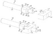
- FIG. 1is a perspective view of an example embodiment of a fiber optic connector made in accordance with the present invention.
- FIG. 2is an exploded view in perspective of the example connector shown in FIG. 1 .
- FIG. 3is a side view of the example connector shown in FIG. 1 .
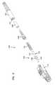
- FIG. 4is a cross-sectional view taken along line C—C of the connector shown in FIG. 3 .
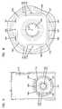
- FIG. 5is a rear view of the connector of FIG. 1 showing the front housing with the hub and ferrule included.
- FIG. 6is an expanded view of a portion of the front housing of the connector of FIG. 5 showing the engagement of the anti-rotation portion of the hub with the anti-rotation seat of the front housing.
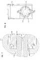
- FIG. 7is an expanded view of a portion of the connector of FIG. 4 showing the engagement of the anti-rotation portion of the hub with the contact lines of the anti-rotation seat.
- FIG. 8is a rear view of the connector of FIG. 1 showing the front housing with the hub and ferrule removed.
- FIG. 9is an expanded view of a portion of the front housing of the connector of FIG. 8 illustrating the contact lines of the anti-rotation seat of the front housing.
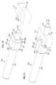
- FIG. 10is a perspective view of an example embodiment of a hub and ferrule assembly and an example anti-rotation seat including contact lines shown in isolation and made in accordance with the present invention.
- FIG. 11is a perspective view of the hub and ferrule assembly and the anti-rotation seat of FIG. 10 shown in an engaged position.
- FIG. 12is an enlarged cross-sectional side view of a ferrule and fiber of an angled physical contact (APC) connector.
- APCangled physical contact
- FIGS. 1-3illustrate an example embodiment of a connector 100 made in accordance with the present invention.
- the connector 100includes a front housing 110 , a rear housing 140 , a crimp ring 395 , and a boot 150 with a bore 152 .
- a hub/ferrule assembly 120with a hub 122 and a ferrule 124 .
- the hub 122includes an anti-rotation portion 128 and an elongated cylindrical rear portion 123 .
- the hub 122is connected to the ferrule 124 , such as with adhesive or an interference fit.
- a spring 130is also provided.
- a fiber optic cable 101is shown including a fiber 102 and an inner jacket 103 .
- a reinforcing layer 400 and an outer jacket 401surround the fiber 102 and the inner jacket 103 .
- the crimp ring 395secures the reinforcing layer 400 to the connector 100 .
- the connector 100includes a spring-biased pivoting front cover 105 which biases the cover 105 toward the closed position (as shown in FIG. 3 ) or the open position as the cover 105 is moved in a direction F. Further details of the exterior features of the connector 100 and mating adapter are shown and described in U.S. Pat. No. 6,142,676, the disclosure of which is hereby incorporated by reference.
- a latch 107latches connector 100 to the adapter.
- Guides 108engage rails on the adapter to guide the connector 100 into the adapter.
- the connector 100may be tunable so that the ferrule and hub assembly 120 may be pushed back, rotated, and released to tune the connector. Alternatively, the connector 100 may not be tunable.
- the present inventionis applicable to tunable and non-tunable connectors.
- the front housing 110 of the connector 100extends along a longitudinal axis 200 and defines an anti-rotation seat 112 and a cavity 114 .
- the ferrule 124extends through a front bore 116 of the front housing 110 and includes a passage 118 extending through a face 125 of the ferrule 124 .
- the anti-rotation portion 128 of the hub 122is slidingly engaged along the longitudinal axis 200 in the anti-rotation seat 112 , as described further below.
- the spring 130surrounds the elongated cylindrical rear portion 123 of the hub 122 .
- the spring 130is captured between the anti-rotation portion 128 and a surface 146 of the rear housing 140 .
- the spring 130functions to bias the anti-rotation portion 128 of the hub 122 into the anti-rotation seat 112 of the front housing 110 .
- the spring 130also functions to bias the ferrule 124 in a forward direction through the front bore 116 .
- the elongated cylindrical rear portion 123 of the hub 122extends into the cavity 114 of the front housing 110 .
- the hub 122includes a passage 119 extending along the longitudinal axis 200 .
- An outer surface 143 of the rear housing 140is held engagingly in a rear bore 117 the front housing 110 .
- the rear housing 140includes a passage 147 .
- a rear portion 145 of the rear housing 140extends along the longitudinal axis 200 into the bore 152 of the boot 150 .
- the crimp ring 395is slid over the rear portion 145 and the reinforcing layer 400 , and crimped in place over the rear portion 145 .
- Arms 151 of the boot 150extend over tabs 144 formed by the rear portion 145 to hold the rear housing 140 to the boot 150 .
- a passage 152 extending through the boot 150is coaxially aligned with passage 147 of the rear housing 140 and passage 119 of the hub 122 .
- the passage 119is coaxially aligned with the passage 118 of the ferrule 124 and is sized to receive a bare fiber of a fiber optic cable.
- the rear housing 140is held to front housing 110 with an interference fit.
- the cable 101is extended through the passages 152 and 147 , and the fiber 102 is extended through the passages 118 and is glued to the ferrule 124 .
- the jacket 103extends through the passage 119 and can abut the ferrule 124 .
- the jacket 103is glued to the hub 122 .
- the anti-rotation portion 128includes opposing surfaces 190 and 191 and opposing surfaces 192 and 193 , as well as edges 194 - 197 .
- the anti-rotation portion 128includes a plurality of sides and the anti-rotation seat 112 defines a seat of a complementary geometry, as shown in FIGS. 5 and 6 .
- Engagement surfaces 181 - 188 formed by the anti-rotation seat 112are configured to engage the opposing surfaces 190 - 193 of the anti-rotation portion 128 of the hub 122 .
- the anti-rotation portion 128 and the anti-rotation seat 112allow for sliding along the longitudinal axis 200 , but prevent significant relative rotation. Other mating shapes and configurations are also possible.
- the complementary fit between the anti-rotation seat 112 and the anti-rotation portion 128is designed to maintain the ferrule 124 in a specified orientation with respect to the longitudinal axis 200 of the connector 100 .
- small variations in tolerances between the anti-rotation seat 112 and the anti-rotation portion 128may cause the ferrule 124 to become misaligned a few degrees with respect to the longitudinal axis 200 , thereby causing the face 125 of the ferrule 124 to be slightly misaligned, increasing the insertion loss when the connector 100 is mated to another connector through an adapter.
- Such misalignmentcan occur during initial assembly.
- Such misalignmentcan also occur when an end face of an APC connector is mated with an end face of another APC connector, and then one connector is removed.
- the spring biasreturns the ferrule 124 and the hub 122 to the front position.
- the longitudinally extending surfaces of the anti-rotation portion 128 and the anti-rotation seat 112maintain the general rotational positions of the hub 122 and the front housing 110 , but small variations may be introduced. If not corrected, the next connection of the connector may result in rotationally misaligned end faces.
- the anti-rotation portion 128includes tapered surfaces or regions 220 and 221 which extend at an angle with respect to the longitudinal axis 200 to the end face 225 of the anti-rotation portion 128 . These tapered regions 220 and 221 engage contact lines 215 and 216 , respectively, formed in the anti-rotation seat 112 .
- the contact lines 215 and 216function to guide and maintain the anti-rotation portion 128 of the hub 122 in proper alignment with respect to the longitudinal axis 200 .
- the face 125 of the ferrule 124 and associated fiber 102will also be properly maintained in alignment.
- the contact lines 215 and 216are shown in FIGS. 7 and 8 , which provide rear views through the bore 117 of the front housing 110 with the hub and ferrule assembly 110 removed.
- Each contact linecomprises two separate and longitudinally-aligned edges formed by the anti-rotation seat 112 .
- the contact line 215is positioned opposite to and parallel with the contact line 216 so that when the tapered regions 220 and 221 engage the contact lines 215 and 216 , the anti-rotation portion 218 is held at a known orientation with respect to the longitudinal axis 200 .
- the anti-rotation seat 112may also include a second set of parallel contact lines 217 and 218 .
- This second set of contact lines 217 and 218is positioned at a 45-degree angle about the longitudinal axis 200 with respect to the set of contact lines 215 and 216 .
- the second set of contact lines 217 and 218can be used to provide additional rotational positions for the ferrule 122 and associated fiber 102 for tuning.
- a description of how the connector 100 may be tuned, if desired,is provided below.
- Lines 319 , 320 , 321 , and 322may preferably, but need not, be formed so that they act as non-contact lines rather than contact lines. This is accomplished by, for example, making a dimension G extending between contact lines 215 and 216 slightly smaller in size than a dimension H extending between non-contact lines 319 and 320 . In this configuration, when the hub 122 is biased towards the front of the housing 110 , the tapered regions 220 and 221 engage the contact lines 215 and 216 because of the smaller dimension G between them. The hub 122 therefore fails to contact the non-contact lines 319 and 320 because of the larger dimension H. It is preferably to include non-contact lines 319 , 320 , 321 , and 322 so that manufacturing tolerances for the anti-rotation seat 112 and the anti-rotation portion 128 can more easily be met.
- FIGS. 10 and 11The engagement between the contact lines of the anti-rotation seat and the tapered regions of the anti-rotation portion of the hub is illustrated in FIGS. 10 and 11 .
- FIG. 10a representation of a portion of an anti-rotation seat 112 ′ is shown.
- the anti-rotation seat 112 ′includes contact lines 215 ′ and 216 ′ and bore 116 ′.
- the hub 122 and associated ferrule 124are shown spaced apart from the anti-rotation seat 112 ′.
- the hub 122is shown engaged with the seat 112 ′.
- the tapered regions 220 and 221engage the contact lines 216 ′ and 215 ′, respectively.
- the hub 122is aligned with respect to the anti-rotation seat 112 ′ and the longitudinal axis 200 of the connector 100 .
- the face 125 of the ferrule 124is also maintained in alignment with respect to the longitudinal axis 200 .
- the ferrule 124 and the optical fiber 102 (not shown) extending from the passage 119 through the ferrule 124are maintained at a known orientation with respect to the longitudinal axis 200 of the connector 100 so that the ferrule 124 of the connector 100 can mate with a ferrule of an opposing connector through an adapter. Should the hub 122 become misaligned when separated from the seat 112 ′, upon re-engagement of surfaces 220 and 221 with lines 215 ′ and 216 ′, realignment results.
- the anti-rotation portion 128further includes tapered regions 222 and 223 positioned opposite to and in a parallel arrangement with respect to one another so that the hub 122 can be pushed or pulled, rotated about the longitudinal axis 200 of the connector 100 , and then re-engage the contact lines 215 ′ and 216 ′ on the tapered regions 222 and 223 .
- Tuning of the connector 100is accomplished by longitudinally pushing the ferrule 124 against the spring bias until the longitudinally extending surfaces of the anti-rotation seat 112 clear the anti-rotation portion 128 of the hub 122 . Then hub 122 is rotated to a second position to re-orient the ferrule 124 relative to the front housing 110 .
- the connector 100is tuned with respect to the exterior structure matable with an adapter of the type in U.S. Pat. No. 6,142,676.
- the configuration of the connector 100is such that it is keyed so that it can only be received in the adapter in one orientation.
- the orientation of the face 125 of the ferrule 124may be particularly important for an angled physical contact connector, in which the end face of the ferrule must be maintained at a specified angle with respect to the longitudinal axis of the connector.
- the angle ⁇is eight degrees, as shown in FIG. 12 .
Landscapes
- Physics & Mathematics (AREA)
- General Physics & Mathematics (AREA)
- Optics & Photonics (AREA)
- Mechanical Coupling Of Light Guides (AREA)
Abstract
Description
Claims (17)
Priority Applications (4)
| Application Number | Priority Date | Filing Date | Title |
|---|---|---|---|
| US10/060,970US6916120B2 (en) | 2002-01-30 | 2002-01-30 | Fiber optic connector and method |
| US11/116,587US7147385B2 (en) | 2002-01-30 | 2005-04-27 | Fiber optic connector and method |
| US11/534,513US7371082B2 (en) | 2002-01-30 | 2006-09-22 | Fiber optic connector and method |
| US12/098,003US7891883B2 (en) | 2002-01-30 | 2008-04-04 | Fiber optic connector and method |
Applications Claiming Priority (1)
| Application Number | Priority Date | Filing Date | Title |
|---|---|---|---|
| US10/060,970US6916120B2 (en) | 2002-01-30 | 2002-01-30 | Fiber optic connector and method |
Related Child Applications (1)
| Application Number | Title | Priority Date | Filing Date |
|---|---|---|---|
| US11/116,587ContinuationUS7147385B2 (en) | 2002-01-30 | 2005-04-27 | Fiber optic connector and method |
Publications (2)
| Publication Number | Publication Date |
|---|---|
| US20030142919A1 US20030142919A1 (en) | 2003-07-31 |
| US6916120B2true US6916120B2 (en) | 2005-07-12 |
Family
ID=27610119
Family Applications (4)
| Application Number | Title | Priority Date | Filing Date |
|---|---|---|---|
| US10/060,970Expired - LifetimeUS6916120B2 (en) | 2002-01-30 | 2002-01-30 | Fiber optic connector and method |
| US11/116,587Expired - LifetimeUS7147385B2 (en) | 2002-01-30 | 2005-04-27 | Fiber optic connector and method |
| US11/534,513Expired - LifetimeUS7371082B2 (en) | 2002-01-30 | 2006-09-22 | Fiber optic connector and method |
| US12/098,003Active2029-08-12US7891883B2 (en) | 2002-01-30 | 2008-04-04 | Fiber optic connector and method |
Family Applications After (3)
| Application Number | Title | Priority Date | Filing Date |
|---|---|---|---|
| US11/116,587Expired - LifetimeUS7147385B2 (en) | 2002-01-30 | 2005-04-27 | Fiber optic connector and method |
| US11/534,513Expired - LifetimeUS7371082B2 (en) | 2002-01-30 | 2006-09-22 | Fiber optic connector and method |
| US12/098,003Active2029-08-12US7891883B2 (en) | 2002-01-30 | 2008-04-04 | Fiber optic connector and method |
Country Status (1)
| Country | Link |
|---|---|
| US (4) | US6916120B2 (en) |
Cited By (50)
| Publication number | Priority date | Publication date | Assignee | Title |
|---|---|---|---|---|
| US20050117850A1 (en)* | 2001-03-08 | 2005-06-02 | Luc Milette | Keyed fibre optic connector |
| US20050232553A1 (en)* | 2004-04-14 | 2005-10-20 | Holmquist Marlon E | Fiber optic connector and method |
| US20050232554A1 (en)* | 2002-01-30 | 2005-10-20 | Adc Telecommunications, Inc. | Fiber optic connector and method |
| US20080013889A1 (en)* | 2003-09-22 | 2008-01-17 | Luc Milette | Fibre optic connector keying system |
| US20080031573A1 (en)* | 2006-08-01 | 2008-02-07 | Scott Droege | Dual inner diameter ferrule device and method |
| US20080080815A1 (en)* | 2004-06-30 | 2008-04-03 | Lee Jae-Soo | Optical Connector |
| US20080175546A1 (en)* | 2007-01-24 | 2008-07-24 | Yu Lu | Fiber optic connector mechanical interface converter |
| US20080226234A1 (en)* | 2007-03-13 | 2008-09-18 | Scott Droege | Fiber Optic Connector with Protective Cap |
| US20080273840A1 (en)* | 2007-05-06 | 2008-11-06 | Yu Lu | Interface converter for sc fiber optic connectors |
| US20080310796A1 (en)* | 2007-06-18 | 2008-12-18 | Yu Lu | Hardened Female Fiber Optic Connector |
| US20090003793A1 (en)* | 2007-06-28 | 2009-01-01 | Verizon Services Corp. | Fiber optic connector |
| US20090003772A1 (en)* | 2007-05-06 | 2009-01-01 | Yu Lu | Mechanical interface converter for making non-ruggedized fiber optic connectors compatible with a ruggedized fiber optic adapter |
| US20090148102A1 (en)* | 2007-12-11 | 2009-06-11 | Yu Lu | Hardened Fiber Optic Connector Compatible with Hardened and Non-Hardened Fiber Optic Adapters |
| US7572065B2 (en) | 2007-01-24 | 2009-08-11 | Adc Telecommunications, Inc. | Hardened fiber optic connector |
| US7591595B2 (en) | 2007-01-24 | 2009-09-22 | Adc Telelcommunications, Inc. | Hardened fiber optic adapter |
| US20090304335A1 (en)* | 2008-04-21 | 2009-12-10 | Adc Telecommunications, Inc. | Hardened Fiber Optic Connector with Connector Body Joined to Cylindrical Cable by Unitary Housing |
| US20100008630A1 (en)* | 2005-11-01 | 2010-01-14 | Molex Incorporated | Locking Mechanism for Optical Tranceivers |
| WO2010118031A1 (en) | 2009-04-06 | 2010-10-14 | Adc Telecommunications, Inc. | Fiber optic connector and method for assembling |
| USRE42522E1 (en) | 2003-09-08 | 2011-07-05 | Adc Telecommunications, Inc. | Ruggedized fiber optic connection |
| US8753022B2 (en) | 2010-11-30 | 2014-06-17 | Adc Telecommunications, Inc. | LC connector and method of assembly |
| US8989541B2 (en) | 2006-08-01 | 2015-03-24 | Adc Telecommunications, Inc. | Cable and dual inner diameter ferrule device with smooth internal contours and method |
| US9146362B2 (en) | 2012-09-21 | 2015-09-29 | Adc Telecommunications, Inc. | Insertion and removal tool for a fiber optic ferrule alignment sleeve |
| US9455786B2 (en)* | 2013-11-29 | 2016-09-27 | Delta Electronics, Inc. | Optical transceiver |
| US20160334593A1 (en)* | 2005-06-30 | 2016-11-17 | Weatherford Technology Holdings, Llc | Optical waveguide feedthrough assembly |
| US10302874B2 (en) | 2015-05-15 | 2019-05-28 | Commscope Telecommunications (Shanghai) Co., Ltd. | Alignment sleeve assembly and fiber optic adapter |
| US10444443B2 (en) | 2013-06-27 | 2019-10-15 | CommScope Connectivity Belgium BVBA | Fiber optic cable anchoring device for use with fiber optic connectors and methods of using the same |
| US20200018907A1 (en)* | 2017-12-13 | 2020-01-16 | Shenzhen Fibercan Optical Co., Ltd. | An optical fiber connector |
| USD884706S1 (en)* | 2017-03-27 | 2020-05-19 | Koninklijke Philps N.V. | Connector housing for medical optical fibers |
| US11150412B2 (en) | 2018-01-31 | 2021-10-19 | Commscope Technologies Llc | Tunable fiber optic connectors |
| US11215768B2 (en) | 2017-06-28 | 2022-01-04 | Corning Research & Development Corporation | Fiber optic connectors and connectorization employing adhesive admitting adapters |
| US11294133B2 (en) | 2019-07-31 | 2022-04-05 | Corning Research & Development Corporation | Fiber optic networks using multiports and cable assemblies with cable-to-connector orientation |
| US11300746B2 (en) | 2017-06-28 | 2022-04-12 | Corning Research & Development Corporation | Fiber optic port module inserts, assemblies and methods of making the same |
| US11487073B2 (en) | 2019-09-30 | 2022-11-01 | Corning Research & Development Corporation | Cable input devices having an integrated locking feature and assemblies using the cable input devices |
| US11536921B2 (en) | 2020-02-11 | 2022-12-27 | Corning Research & Development Corporation | Fiber optic terminals having one or more loopback assemblies |
| US11604320B2 (en) | 2020-09-30 | 2023-03-14 | Corning Research & Development Corporation | Connector assemblies for telecommunication enclosures |
| US11650388B2 (en) | 2019-11-14 | 2023-05-16 | Corning Research & Development Corporation | Fiber optic networks having a self-supporting optical terminal and methods of installing the optical terminal |
| US11668890B2 (en) | 2017-06-28 | 2023-06-06 | Corning Research & Development Corporation | Multiports and other devices having optical connection ports with securing features and methods of making the same |
| US11686913B2 (en) | 2020-11-30 | 2023-06-27 | Corning Research & Development Corporation | Fiber optic cable assemblies and connector assemblies having a crimp ring and crimp body and methods of fabricating the same |
| US11703646B2 (en) | 2017-06-28 | 2023-07-18 | Corning Research & Development Corporation | Multiports and optical connectors with rotationally discrete locking and keying features |
| US11880076B2 (en) | 2020-11-30 | 2024-01-23 | Corning Research & Development Corporation | Fiber optic adapter assemblies including a conversion housing and a release housing |
| US11886010B2 (en) | 2019-10-07 | 2024-01-30 | Corning Research & Development Corporation | Fiber optic terminals and fiber optic networks having variable ratio couplers |
| US11927810B2 (en) | 2020-11-30 | 2024-03-12 | Corning Research & Development Corporation | Fiber optic adapter assemblies including a conversion housing and a release member |
| US20240103235A1 (en)* | 2021-02-26 | 2024-03-28 | Sumitomo Electric Optifrontier Co., Ltd. | Optical connector |
| US11947167B2 (en) | 2021-05-26 | 2024-04-02 | Corning Research & Development Corporation | Fiber optic terminals and tools and methods for adjusting a split ratio of a fiber optic terminal |
| US11994722B2 (en) | 2020-11-30 | 2024-05-28 | Corning Research & Development Corporation | Fiber optic adapter assemblies including an adapter housing and a locking housing |
| US12013577B2 (en) | 2011-10-10 | 2024-06-18 | Commscope Technologies Llc | Cable and dual inner diameter ferrule device with smooth internal contours and method |
| US12019279B2 (en) | 2019-05-31 | 2024-06-25 | Corning Research & Development Corporation | Multiports and other devices having optical connection ports with sliding actuators and methods of making the same |
| US12044894B2 (en) | 2018-12-28 | 2024-07-23 | Corning Research & Development Corporation | Multiport assemblies including mounting features or dust plugs |
| US12271040B2 (en) | 2017-06-28 | 2025-04-08 | Corning Research & Development Corporation | Fiber optic extender ports, assemblies and methods of making the same |
| US12372727B2 (en) | 2020-10-30 | 2025-07-29 | Corning Research & Development Corporation | Female fiber optic connectors having a rocker latch arm and methods of making the same |
Families Citing this family (90)
| Publication number | Priority date | Publication date | Assignee | Title |
|---|---|---|---|---|
| US6918704B2 (en)* | 2003-01-30 | 2005-07-19 | Panduit Corp. | Tunable fiber optic connector |
| USD528505S1 (en)* | 2003-12-03 | 2006-09-19 | Panduit Corp. | Fiber optic connector |
| TWD109277S1 (en)* | 2004-06-30 | 2006-02-21 | 日本壓端子製造股份有限公司 | Optical connector plug |
| JP2006267649A (en)* | 2005-03-24 | 2006-10-05 | Seikoh Giken Co Ltd | Optical connector |
| US8087833B2 (en)* | 2007-02-08 | 2012-01-03 | Diamond Sa | Plug parts for an optical plug connection |
| US7534050B2 (en) | 2007-04-13 | 2009-05-19 | Adc Telecommunications, Inc. | Field terminatable fiber optic connector assembly |
| US8201322B2 (en)* | 2009-05-29 | 2012-06-19 | Schratz Gary F | Fiber optic connector tooling device |
| US8452152B2 (en)* | 2010-06-29 | 2013-05-28 | Juniper Networks, Inc. | Fixed attenuation air gap interface for a multimode optical fiber interconnection |
| US8702323B2 (en) | 2011-03-15 | 2014-04-22 | Adc Telecommunications, Inc. | Strain relief boot for a fiber optic connector |
| US8636425B2 (en) | 2011-03-15 | 2014-01-28 | Adc Telecommunications, Inc. | Fiber optic connector |
| US9188747B2 (en) | 2011-05-23 | 2015-11-17 | Senko Advanced Components, Inc. | True one piece housing fiber optic adapter |
| US8931964B2 (en) | 2011-06-08 | 2015-01-13 | Adc Telecommunications, Inc. | Loose tube fiber optic cable assembly |
| CN104011572B (en) | 2011-11-23 | 2016-03-16 | Adc电信公司 | Multi-fiber fiber optic connector |
| RU2619816C2 (en) | 2012-02-07 | 2017-05-18 | Тайко Электроникс Райхем Бвба | Cable terminal assembly and method for fixing fiber-optic cable to connector |
| RU2014138122A (en)* | 2012-02-20 | 2016-04-10 | Адс Телекоммьюникейшнз, Инк. | FIBER OPTICAL CONNECTOR, FIBER OPTICAL CONNECTOR AND CABLE ASSEMBLY AND METHODS FOR THEIR MANUFACTURE |
| US9176285B2 (en) | 2012-05-03 | 2015-11-03 | Adc Telecommunications, Inc. | Fiber optic connector |
| US8974124B2 (en)* | 2012-08-16 | 2015-03-10 | Senko Advanced Components, Inc. | Fiber optic connector |
| US8939654B2 (en) | 2012-09-27 | 2015-01-27 | Adc Telecommunications, Inc. | Ruggedized multi-fiber fiber optic connector with sealed dust cap |
| WO2014164880A1 (en) | 2013-03-11 | 2014-10-09 | Adc Telecommunications, Inc. | Fiber optic connector and fiber optic cable assembly with fiber optic cable anchored to boot of fiber optic connector |
| US9268103B2 (en) | 2013-05-10 | 2016-02-23 | Senko Advanced Components, Inc. | Interlockable fiber optic connector adaptors |
| US9360649B2 (en) | 2013-05-22 | 2016-06-07 | Senko Advanced Components, Inc. | Cable guide for fiber optic cables |
| WO2015034961A1 (en) | 2013-09-06 | 2015-03-12 | Adc Telecommunications, Inc. | Optical fiber connector and cable assembly with dual diameter crimp sleeve |
| US9618703B2 (en) | 2013-10-03 | 2017-04-11 | Senko Advanced Components, Inc. | Connector housing for securing an optical cable and methods of use and manufacture thereof |
| US9477049B2 (en) | 2013-12-20 | 2016-10-25 | Senko Advanced Components, Inc. | Lockable connectors and connection assemblies |
| US9535230B2 (en) | 2014-01-31 | 2017-01-03 | Senko Advanced Components, Inc. | Integrated fiber optic cable fan-out connector |
| US9297964B2 (en) | 2014-04-18 | 2016-03-29 | Senko Advanced Components, Inc. | Optical fiber connector assembly |
| US9274287B2 (en) | 2014-05-13 | 2016-03-01 | Senko Advanced Components, Inc. | Optical fiber connector and ferrule |
| US9720185B2 (en) | 2014-05-23 | 2017-08-01 | Commscope Technologies Llc | Systems and method for processing optical cable assemblies |
| US9618702B2 (en) | 2014-06-09 | 2017-04-11 | Senko Advanced Components, Inc. | Reduced-profile data transmission element connectors, adapters, and connection assemblies thereof |
| US9599778B2 (en) | 2014-10-22 | 2017-03-21 | Senko Advanced Components, Inc. | Latching connector with remote release |
| JP5860948B1 (en)* | 2014-12-24 | 2016-02-16 | 日本航空電子工業株式会社 | Plug with built-in connector |
| US9494745B2 (en) | 2015-01-16 | 2016-11-15 | Senko Advanced Components, Inc. | Sealable communication cable connection assemblies |
| US9658409B2 (en) | 2015-03-03 | 2017-05-23 | Senko Advanced Components, Inc. | Optical fiber connector with changeable polarity |
| US9684139B2 (en) | 2015-05-29 | 2017-06-20 | Senko Advanced Components, Inc. | Optical fiber connector with changeable gender |
| JP6775307B2 (en)* | 2016-03-11 | 2020-10-28 | オリンパス株式会社 | Optical connector |
| EP3430451A1 (en) | 2016-03-17 | 2019-01-23 | Corning Optical Communications LLC | Tunable optical fiber connector and tuning methods for optical fiber cable assemblies |
| JP6247721B1 (en)* | 2016-06-24 | 2017-12-13 | 日本航空電子工業株式会社 | Optical connector plug |
| US9726830B1 (en) | 2016-06-28 | 2017-08-08 | Senko Advanced Components, Inc. | Connector and adapter system for two-fiber mechanical transfer type ferrule |
| CN106405770A (en)* | 2016-11-22 | 2017-02-15 | 上海乐通通信设备(集团)股份有限公司 | Rubber-insulated wire jumping fiber manufacture method |
| US10228521B2 (en) | 2016-12-05 | 2019-03-12 | Senko Advanced Components, Inc. | Narrow width adapters and connectors with modular latching arm |
| US10078188B1 (en) | 2016-12-05 | 2018-09-18 | Senko Advanced Components, Inc. | Springless push/pull fiber optic connector |
| US10725248B2 (en) | 2017-01-30 | 2020-07-28 | Senko Advanced Components, Inc. | Fiber optic receptacle with integrated device therein incorporating a behind-the-wall fiber optic receptacle |
| CN110249248B (en) | 2017-01-30 | 2021-07-27 | 扇港元器件股份有限公司 | Optical connectors with reversible polarity |
| US10185100B2 (en)* | 2017-01-30 | 2019-01-22 | Senko Advanced Components, Inc | Modular connector and adapter assembly using a removable anchor device |
| US10871619B2 (en)* | 2017-01-30 | 2020-12-22 | Senko Advanced Components, Inc. | Cassette assembly for a plural of fiber optic receptacles |
| US11333836B2 (en) | 2017-01-30 | 2022-05-17 | Senko Advanced Components, Inc. | Adapter for optical connectors |
| US10416394B2 (en) | 2017-01-30 | 2019-09-17 | Senko Advanced Components, Inc. | Fiber optic receptacle with integrated device therein |
| US10444444B2 (en) | 2017-01-30 | 2019-10-15 | Senko Advanced Components, Inc. | Remote release tab connector assembly |
| US10359583B2 (en) | 2017-04-07 | 2019-07-23 | Senko Advanced Components, Inc. | Behind the wall optical connector with reduced components |
| US10989884B2 (en) | 2017-04-07 | 2021-04-27 | Senko Advanced Components, Inc. | Behind the wall optical connector with reduced components |
| US10754098B2 (en) | 2017-04-07 | 2020-08-25 | Senko Advanced Components, Inc. | Behind the wall optical connector with reduced components |
| US10209461B2 (en) | 2017-04-07 | 2019-02-19 | Senko Advanced Components | Behind the wall optical connector with reduced components |
| US10718910B2 (en) | 2017-05-03 | 2020-07-21 | Senko Advanced Components, Inc | Field terminated ruggedized fiber optic connector system |
| US10401576B2 (en) | 2017-05-10 | 2019-09-03 | Senko Advanced Components, Inc. | MPO micro-latch-lock connector |
| US10146016B1 (en) | 2017-05-10 | 2018-12-04 | Senko Advanced Components, Inc | MPO micro-latchlock connector |
| US10295759B2 (en) | 2017-05-18 | 2019-05-21 | Senko Advanced Components, Inc. | Optical connector with forward-biasing projections |
| US10359576B2 (en) | 2017-06-15 | 2019-07-23 | Senko Advanced Components, Inc. | SC low profile connector with optional boot |
| US10281669B2 (en) | 2017-07-14 | 2019-05-07 | Senko Advance Components, Inc. | Ultra-small form factor optical connectors |
| US10718911B2 (en) | 2017-08-24 | 2020-07-21 | Senko Advanced Components, Inc. | Ultra-small form factor optical connectors using a push-pull boot receptacle release |
| US11822133B2 (en) | 2017-07-14 | 2023-11-21 | Senko Advanced Components, Inc. | Ultra-small form factor optical connector and adapter |
| US12001064B2 (en) | 2017-07-14 | 2024-06-04 | Senko Advanced Components, Inc. | Small form factor fiber optic connector with multi-purpose boot |
| US10641972B2 (en) | 2017-08-17 | 2020-05-05 | Senko Advanced Components, Inc | Anti-jam alignment sleeve holder or connector housing for a ferrule assembly |
| US10444442B2 (en) | 2017-11-03 | 2019-10-15 | Senko Advanced Components, Inc. | MPO optical fiber connector |
| US11002923B2 (en) | 2017-11-21 | 2021-05-11 | Senko Advanced Components, Inc. | Fiber optic connector with cable boot release having a two-piece clip assembly |
| US11016250B2 (en)* | 2017-12-19 | 2021-05-25 | Us Conec, Ltd. | Mini duplex connector with push-pull polarity mechanism, carrier, and rail-receiving crimp body |
| WO2019183070A2 (en) | 2018-03-19 | 2019-09-26 | Senko Advanced Components, Inc. | Removal tool for removing a plural of micro optical connectors from an adapter interface |
| EP3776038B1 (en) | 2018-03-28 | 2024-07-03 | Senko Advanced Components Inc. | Small form factor fiber optic connector with multi-purpose boot |
| US11041993B2 (en) | 2018-04-19 | 2021-06-22 | Senko Advanced Components, Inc. | Fiber optic adapter with removable insert for polarity change and removal tool for the same |
| US10921528B2 (en) | 2018-06-07 | 2021-02-16 | Senko Advanced Components, Inc. | Dual spring multi-fiber optic connector |
| CN112088327A (en) | 2018-07-15 | 2020-12-15 | 扇港元器件股份有限公司 | Subminiature Optical Connectors and Adapters |
| US10444441B1 (en) | 2018-08-10 | 2019-10-15 | Senko Advanced Components, Inc. | Pivotable housing for a fiber optic connector |
| US11073664B2 (en) | 2018-08-13 | 2021-07-27 | Senko Advanced Components, Inc. | Cable boot assembly for releasing fiber optic connector from a receptacle |
| WO2020055440A1 (en) | 2018-09-12 | 2020-03-19 | Senko Advanced Componetns, Inc. | Lc type connector with clip-on push/pull tab for releasing connector from a receptacle using a cable boot |
| US10921531B2 (en) | 2018-09-12 | 2021-02-16 | Senko Advanced Components, Inc. | LC type connector with push/pull assembly for releasing connector from a receptacle using a cable boot |
| US11806831B2 (en) | 2018-11-21 | 2023-11-07 | Senko Advanced Components, Inc. | Fixture and method for polishing fiber optic connector ferrules |
| US11175464B2 (en) | 2018-11-25 | 2021-11-16 | Senko Advanced Components, Inc. | Open ended spring body for use in an optical fiber connector |
| US12038613B2 (en) | 2019-03-28 | 2024-07-16 | Senko Advanced Components, Inc. | Behind-the-wall optical connector and assembly of the same |
| US11579379B2 (en) | 2019-03-28 | 2023-02-14 | Senko Advanced Components, Inc. | Fiber optic adapter assembly |
| US11340406B2 (en) | 2019-04-19 | 2022-05-24 | Senko Advanced Components, Inc. | Small form factor fiber optic connector with resilient latching mechanism for securing within a hook-less receptacle |
| WO2020252048A1 (en) | 2019-06-10 | 2020-12-17 | Commscope Technologies Llc | Strain relief boot |
| WO2020252355A1 (en) | 2019-06-13 | 2020-12-17 | Senko Advanced Components, Inc | Lever actuated latch arm for releasing a fiber optic connector from a receptacle port and method of use |
| WO2021011794A1 (en) | 2019-07-17 | 2021-01-21 | Commscope Technologies Llc | Fiber optic connector with anti-wicking epoxy tube |
| WO2021011666A1 (en)* | 2019-07-17 | 2021-01-21 | Commscope Technologies Llc | Tuned fiber optic connector |
| EP3999889A1 (en) | 2019-07-17 | 2022-05-25 | CommScope Technologies LLC | Fiber optic connector with epoxy tube with axial float |
| CN114600018B (en) | 2019-07-23 | 2024-04-09 | 扇港元器件有限公司 | Ultra-small receptacle for receiving a fiber optic connector opposite a ferrule assembly |
| US11353664B1 (en) | 2019-08-21 | 2022-06-07 | Senko Advanced Components, Inc. | Fiber optic connector |
| USD970447S1 (en)* | 2019-10-24 | 2022-11-22 | 3P Design | Optical fiber connector |
| WO2021097304A1 (en) | 2019-11-13 | 2021-05-20 | Senko Advanced Components, Inc. | Fiber optic connector |
| WO2021237127A1 (en)* | 2020-05-21 | 2021-11-25 | US Conec, Ltd | Ferrule seating features for a fiber optic connector |
| CN112230355B (en)* | 2020-09-27 | 2021-12-14 | 华为技术有限公司 | an optical connector |
Citations (25)
| Publication number | Priority date | Publication date | Assignee | Title |
|---|---|---|---|---|
| JPS5774714A (en) | 1980-10-29 | 1982-05-11 | Nec Corp | Optical connector |
| US4579418A (en) | 1982-06-22 | 1986-04-01 | Socapex | Plug for an optical-fiber connector and a connector equipped with said plug |
| US4747659A (en) | 1985-04-02 | 1988-05-31 | Seikoh Giken Co., Ltd. | Optical fiber connector |
| JPH0384801A (en) | 1989-08-28 | 1991-04-10 | Nissan Motor Co Ltd | Structure for diagnosing fixing of bulb |
| US5016970A (en) | 1989-08-22 | 1991-05-21 | Nippon Telegraph And Telephone Corp. | Ferrule for optical fiber transmitting linearly polarized light and optical fiber connector using this ferrule |
| US5096276A (en) | 1988-02-23 | 1992-03-17 | Amp Incorporated | Sheath connector for an optical cable |
| US5136681A (en) | 1991-07-09 | 1992-08-04 | Seikoh Giken Co., Ltd. | Optical powder attenuator of variable attenuation type |
| US5142598A (en) | 1991-08-28 | 1992-08-25 | Porta Systems Corp. | Fiber optic connector having snap ring adjustment means |
| US5146525A (en) | 1991-09-03 | 1992-09-08 | Porta Systems Corp. | Fiber optic plug connector having optical center adjustment means |
| US5212752A (en) | 1992-05-27 | 1993-05-18 | At&T Bell Laboratories | Optical fiber ferrule connector having enhanced provisions for tuning |
| US5257333A (en) | 1989-10-13 | 1993-10-26 | Anders Nodfelt | Connecting device for interconnection of optical fibres |
| US5317663A (en) | 1993-05-20 | 1994-05-31 | Adc Telecommunications, Inc. | One-piece SC adapter |
| US5390269A (en) | 1992-12-23 | 1995-02-14 | Methode Electronics, Inc. | Fiber optic connector with high resolution tunable fiber holder |
| JPH0756053A (en) | 1993-08-18 | 1995-03-03 | Nec Corp | Whirl stop structure for optical connector ferrule |
| US5633970A (en) | 1995-05-23 | 1997-05-27 | Minnesota Mining And Manufacturing Company | Device with internal asymmetrical features for rotational alignment of non-symmetrical articles |
| US5682451A (en) | 1995-05-23 | 1997-10-28 | Minnesota Mining And Manufacturing Company | Device with internal features for rotational alignment of non-cylindrically symmetrical optical elements |
| US5734769A (en) | 1997-01-17 | 1998-03-31 | Adc Telecommunications, Inc. | Optical fiber ferrule |
| US5852694A (en) | 1996-07-10 | 1998-12-22 | Mitsubishi Cable Industries, Ltd. | High power fiber optic connector |
| US5946436A (en) | 1997-07-22 | 1999-08-31 | Seikoh Giken Co., Ltd. | Structure of optical connector and aligning method |
| US6142676A (en) | 1997-05-20 | 2000-11-07 | Adc Telecommunications, Inc. | Fiber connector and adaptor |
| EP1072914A2 (en) | 1999-07-28 | 2001-01-31 | Lucent Technologies Inc. | Optical fiber connector tuning tool for eccentricity optimisation |
| EP1072915A2 (en) | 1999-07-28 | 2001-01-31 | Lucent Technologies Inc. | Optical fiber connector tuning wrench |
| US6428215B1 (en)* | 2000-12-27 | 2002-08-06 | Adc Telecommunications, Inc. | Tunable fiber optic connector and method for assembling |
| US6550979B1 (en)* | 2001-10-19 | 2003-04-22 | Corning Cable Systems Llc | Floating connector subassembly and connector including same |
| US6550978B2 (en)* | 2000-01-06 | 2003-04-22 | Diamond S.A. | Plug part for an optical plug-and-socket connection and method for its assembly |
Family Cites Families (22)
| Publication number | Priority date | Publication date | Assignee | Title |
|---|---|---|---|---|
| US5135477A (en)* | 1984-10-29 | 1992-08-04 | Medtronic, Inc. | Iontophoretic drug delivery |
| US5148525A (en)* | 1987-11-30 | 1992-09-15 | Nec Corporation | Microprogram-controlled type bus control circuit |
| US5496266A (en)* | 1990-04-30 | 1996-03-05 | Alza Corporation | Device and method of iontophoretic drug delivery |
| US6582416B2 (en)* | 1990-11-01 | 2003-06-24 | Robert Tapper | Iontophoretic treatment system |
| US6238381B1 (en)* | 1990-11-01 | 2001-05-29 | Robert Tapper | Iontophoretic treatment system |
| JPH0794587B2 (en)* | 1990-11-14 | 1995-10-11 | 日本ペイント株式会社 | Novel room temperature curable resin composition and coating composition |
| US5096249A (en)* | 1991-01-30 | 1992-03-17 | Troy Hines | Anti-theft vehicle container |
| US5356632A (en)* | 1991-09-12 | 1994-10-18 | S.I. Scientific Innovations Ltd. | Transdermal drug delivery device |
| JPH07507465A (en)* | 1992-06-02 | 1995-08-24 | アルザ・コーポレーション | Iontophoretic drug administration device |
| JP3488466B2 (en)* | 1992-06-02 | 2004-01-19 | アルザ・コーポレーション | Electric drive drug delivery device |
| US5624425A (en)* | 1995-04-05 | 1997-04-29 | The Procter & Gamble Company | Localized application of fine denier fibers onto a spunbonded web for optimization of leg cuff hydrophobicity in diapers and pads |
| US5678545A (en)* | 1995-05-04 | 1997-10-21 | Stratbucker; Robert A. | Anisotropic adhesive multiple electrode system, and method of use |
| IT1289624B1 (en)* | 1996-02-02 | 1998-10-15 | Nordica Spa | PROCEDURE FOR THE PRODUCTION OF SOLES FOR INJECTION SHOES |
| US6102581A (en) | 1998-06-16 | 2000-08-15 | Lucent Technologies Inc. | Optical adapter including a ferrule assembly |
| US6287018B1 (en) | 1999-07-28 | 2001-09-11 | Lucent Technologies Inc. | Tunable optical fiber connector |
| US6293710B1 (en) | 1999-10-06 | 2001-09-25 | Lucent Technologies Inc. | Optical connector having a one-piece housing |
| US6821281B2 (en)* | 2000-10-16 | 2004-11-23 | The Procter & Gamble Company | Microstructures for treating and conditioning skin |
| US6855117B2 (en)* | 2001-08-01 | 2005-02-15 | Johnson & Johnson Consumer Companies, Inc. | Method of treating the skin of a subject |
| KR101028788B1 (en)* | 2001-10-24 | 2011-04-14 | 파워 페이퍼 리미티드 | Controlled Delivery Device and Method of Active Material into Skin |
| US6916120B2 (en)* | 2002-01-30 | 2005-07-12 | Adc Telecommunications, Inc. | Fiber optic connector and method |
| US6866856B2 (en)* | 2002-12-31 | 2005-03-15 | Avon Products, Inc. | Compositions and delivery methods for the treatment of wrinkles, fine lines and hyperhidrosis |
| US6913392B2 (en) | 2003-05-27 | 2005-07-05 | Molex Incorporated | Rotationally adjustable fiber optic connector |
- 2002
- 2002-01-30USUS10/060,970patent/US6916120B2/ennot_activeExpired - Lifetime
- 2005
- 2005-04-27USUS11/116,587patent/US7147385B2/ennot_activeExpired - Lifetime
- 2006
- 2006-09-22USUS11/534,513patent/US7371082B2/ennot_activeExpired - Lifetime
- 2008
- 2008-04-04USUS12/098,003patent/US7891883B2/enactiveActive
Patent Citations (25)
| Publication number | Priority date | Publication date | Assignee | Title |
|---|---|---|---|---|
| JPS5774714A (en) | 1980-10-29 | 1982-05-11 | Nec Corp | Optical connector |
| US4579418A (en) | 1982-06-22 | 1986-04-01 | Socapex | Plug for an optical-fiber connector and a connector equipped with said plug |
| US4747659A (en) | 1985-04-02 | 1988-05-31 | Seikoh Giken Co., Ltd. | Optical fiber connector |
| US5096276A (en) | 1988-02-23 | 1992-03-17 | Amp Incorporated | Sheath connector for an optical cable |
| US5016970A (en) | 1989-08-22 | 1991-05-21 | Nippon Telegraph And Telephone Corp. | Ferrule for optical fiber transmitting linearly polarized light and optical fiber connector using this ferrule |
| JPH0384801A (en) | 1989-08-28 | 1991-04-10 | Nissan Motor Co Ltd | Structure for diagnosing fixing of bulb |
| US5257333A (en) | 1989-10-13 | 1993-10-26 | Anders Nodfelt | Connecting device for interconnection of optical fibres |
| US5136681A (en) | 1991-07-09 | 1992-08-04 | Seikoh Giken Co., Ltd. | Optical powder attenuator of variable attenuation type |
| US5142598A (en) | 1991-08-28 | 1992-08-25 | Porta Systems Corp. | Fiber optic connector having snap ring adjustment means |
| US5146525A (en) | 1991-09-03 | 1992-09-08 | Porta Systems Corp. | Fiber optic plug connector having optical center adjustment means |
| US5212752A (en) | 1992-05-27 | 1993-05-18 | At&T Bell Laboratories | Optical fiber ferrule connector having enhanced provisions for tuning |
| US5390269A (en) | 1992-12-23 | 1995-02-14 | Methode Electronics, Inc. | Fiber optic connector with high resolution tunable fiber holder |
| US5317663A (en) | 1993-05-20 | 1994-05-31 | Adc Telecommunications, Inc. | One-piece SC adapter |
| JPH0756053A (en) | 1993-08-18 | 1995-03-03 | Nec Corp | Whirl stop structure for optical connector ferrule |
| US5633970A (en) | 1995-05-23 | 1997-05-27 | Minnesota Mining And Manufacturing Company | Device with internal asymmetrical features for rotational alignment of non-symmetrical articles |
| US5682451A (en) | 1995-05-23 | 1997-10-28 | Minnesota Mining And Manufacturing Company | Device with internal features for rotational alignment of non-cylindrically symmetrical optical elements |
| US5852694A (en) | 1996-07-10 | 1998-12-22 | Mitsubishi Cable Industries, Ltd. | High power fiber optic connector |
| US5734769A (en) | 1997-01-17 | 1998-03-31 | Adc Telecommunications, Inc. | Optical fiber ferrule |
| US6142676A (en) | 1997-05-20 | 2000-11-07 | Adc Telecommunications, Inc. | Fiber connector and adaptor |
| US5946436A (en) | 1997-07-22 | 1999-08-31 | Seikoh Giken Co., Ltd. | Structure of optical connector and aligning method |
| EP1072914A2 (en) | 1999-07-28 | 2001-01-31 | Lucent Technologies Inc. | Optical fiber connector tuning tool for eccentricity optimisation |
| EP1072915A2 (en) | 1999-07-28 | 2001-01-31 | Lucent Technologies Inc. | Optical fiber connector tuning wrench |
| US6550978B2 (en)* | 2000-01-06 | 2003-04-22 | Diamond S.A. | Plug part for an optical plug-and-socket connection and method for its assembly |
| US6428215B1 (en)* | 2000-12-27 | 2002-08-06 | Adc Telecommunications, Inc. | Tunable fiber optic connector and method for assembling |
| US6550979B1 (en)* | 2001-10-19 | 2003-04-22 | Corning Cable Systems Llc | Floating connector subassembly and connector including same |
Non-Patent Citations (1)
| Title |
|---|
| Suhner Fiberoptic, Adjusting instructions, pp. 1-7, issued Mar. 30, 1994, last amendment May 18, 2001. |
Cited By (152)
| Publication number | Priority date | Publication date | Assignee | Title |
|---|---|---|---|---|
| US7258493B2 (en)* | 2001-03-08 | 2007-08-21 | Belden Cdt (Canada) Inc. | Keyed fibre optic connector |
| US20050117850A1 (en)* | 2001-03-08 | 2005-06-02 | Luc Milette | Keyed fibre optic connector |
| US7891883B2 (en) | 2002-01-30 | 2011-02-22 | Adc Telecommunications, Inc. | Fiber optic connector and method |
| US7371082B2 (en)* | 2002-01-30 | 2008-05-13 | Adc Telecommunications, Inc. | Fiber optic connector and method |
| US20070110371A1 (en)* | 2002-01-30 | 2007-05-17 | Adc Telecommunications, Inc. | Fiber Optic Connector and Method |
| US20050232554A1 (en)* | 2002-01-30 | 2005-10-20 | Adc Telecommunications, Inc. | Fiber optic connector and method |
| US20100322567A1 (en)* | 2002-01-30 | 2010-12-23 | Adc Telecommunications, Inc. | Fiber optic connector and method |
| US7147385B2 (en)* | 2002-01-30 | 2006-12-12 | Adc Telecommunications, Inc. | Fiber optic connector and method |
| USRE42522E1 (en) | 2003-09-08 | 2011-07-05 | Adc Telecommunications, Inc. | Ruggedized fiber optic connection |
| US7674046B2 (en) | 2003-09-22 | 2010-03-09 | Belden Cdt (Canada) Inc. | Fibre optic connector keying system |
| US7699533B2 (en) | 2003-09-22 | 2010-04-20 | Belden Cdt (Canada) Inc. | Back-to-back receptacle |
| US20080013889A1 (en)* | 2003-09-22 | 2008-01-17 | Luc Milette | Fibre optic connector keying system |
| US20080013890A1 (en)* | 2003-09-22 | 2008-01-17 | Luc Milette | Back-to-back receptacle |
| US7530745B2 (en) | 2004-04-14 | 2009-05-12 | Adc Telecommunications, Inc. | Fiber optic connector and method |
| US20050232553A1 (en)* | 2004-04-14 | 2005-10-20 | Holmquist Marlon E | Fiber optic connector and method |
| US20070183721A1 (en)* | 2004-04-14 | 2007-08-09 | Adc Telecommunications, Inc. | Fiber Optic Connector and Method |
| US7201518B2 (en) | 2004-04-14 | 2007-04-10 | Adc Telecommunications, Inc. | Fiber optic connector and method |
| US20080080815A1 (en)* | 2004-06-30 | 2008-04-03 | Lee Jae-Soo | Optical Connector |
| US7712971B2 (en)* | 2004-06-30 | 2010-05-11 | Goldtel Co., Ltd. | Optical connector |
| US10606000B2 (en)* | 2005-06-30 | 2020-03-31 | Weatherford Technology Holdings, Llc | Optical waveguide feedthrough assembly |
| US20160334593A1 (en)* | 2005-06-30 | 2016-11-17 | Weatherford Technology Holdings, Llc | Optical waveguide feedthrough assembly |
| US20100008630A1 (en)* | 2005-11-01 | 2010-01-14 | Molex Incorporated | Locking Mechanism for Optical Tranceivers |
| US10295757B2 (en) | 2006-08-01 | 2019-05-21 | Commscope Technologies Llc | Fiber optic ferrule with smooth internal contours and method of terminating fiber with the ferrule |
| US11397296B2 (en) | 2006-08-01 | 2022-07-26 | Commscope Technologies Llc | Dual inner diameter ferrule device and method |
| US9348095B2 (en) | 2006-08-01 | 2016-05-24 | Commscope Technologies Llc | Cable and dual inner diameter ferrule device with smooth internal contours and method |
| US10942317B2 (en) | 2006-08-01 | 2021-03-09 | Commscope Technologies Llc | Fiber optic ferrule with smooth internal contours |
| US10976503B2 (en) | 2006-08-01 | 2021-04-13 | Commscope Technologies Llc | Dual inner diameter ferrule device and method |
| US10634856B2 (en) | 2006-08-01 | 2020-04-28 | Commscope Technologies Llc | Dual inner diameter ferrule device and method |
| US7341383B2 (en) | 2006-08-01 | 2008-03-11 | Adc Telecommunications, Inc. | Dual inner diameter ferrule device and method |
| US11467353B2 (en) | 2006-08-01 | 2022-10-11 | Commscope Technologies Llc | Cable and dual inner diameter ferrule device with smooth internal contours and method |
| US9477047B2 (en) | 2006-08-01 | 2016-10-25 | Commscope Technologies Llc | Dual inner diameter ferrule device and method |
| US20080031573A1 (en)* | 2006-08-01 | 2008-02-07 | Scott Droege | Dual inner diameter ferrule device and method |
| US20090067789A1 (en)* | 2006-08-01 | 2009-03-12 | Adc Telecommunications, Inc. | Dual inner diameter ferrule device and method |
| US9835806B2 (en) | 2006-08-01 | 2017-12-05 | Commscope Technologies Llc | Fiber optic cable and ferrule with smooth internal contours and method of terminating fiber with the ferrule |
| US12124091B2 (en) | 2006-08-01 | 2024-10-22 | Commscope Technologies Llc | Dual inner diameter ferrule device and method |
| US8989541B2 (en) | 2006-08-01 | 2015-03-24 | Adc Telecommunications, Inc. | Cable and dual inner diameter ferrule device with smooth internal contours and method |
| US10107971B2 (en) | 2006-08-01 | 2018-10-23 | Commscope Technologies Llc | Dual inner diameter ferrule device and method |
| US7452137B2 (en) | 2006-08-01 | 2008-11-18 | Adc Telecommunications, Inc. | Dual inner diameter ferrule device and method |
| US11409057B2 (en) | 2007-01-24 | 2022-08-09 | Commscope Technologies Llc | Hardened fiber optic connector |
| US9664862B2 (en) | 2007-01-24 | 2017-05-30 | Commscope Technologies Llc | Hardened fiber optic connector |
| US20080175546A1 (en)* | 2007-01-24 | 2008-07-24 | Yu Lu | Fiber optic connector mechanical interface converter |
| US12111502B2 (en) | 2007-01-24 | 2024-10-08 | Commscope Technologies Llc | Hardened fiber optic connector |
| US7614797B2 (en) | 2007-01-24 | 2009-11-10 | Adc Telecommunications, Inc. | Fiber optic connector mechanical interface converter |
| US7591595B2 (en) | 2007-01-24 | 2009-09-22 | Adc Telelcommunications, Inc. | Hardened fiber optic adapter |
| US7572065B2 (en) | 2007-01-24 | 2009-08-11 | Adc Telecommunications, Inc. | Hardened fiber optic connector |
| US8770862B2 (en) | 2007-01-24 | 2014-07-08 | Adc Telecommunications, Inc. | Hardened fiber optic connector |
| US10877224B2 (en) | 2007-01-24 | 2020-12-29 | Commscope Technologies Llc | Fiber optic adapter |
| US20080226234A1 (en)* | 2007-03-13 | 2008-09-18 | Scott Droege | Fiber Optic Connector with Protective Cap |
| US7556437B2 (en) | 2007-03-13 | 2009-07-07 | Adc Telecommunications, Inc. | Fiber optic connector with protective cap |
| US7677814B2 (en) | 2007-05-06 | 2010-03-16 | Adc Telecommunications, Inc. | Mechanical interface converter for making non-ruggedized fiber optic connectors compatible with a ruggedized fiber optic adapter |
| US20080273840A1 (en)* | 2007-05-06 | 2008-11-06 | Yu Lu | Interface converter for sc fiber optic connectors |
| US8128294B2 (en) | 2007-05-06 | 2012-03-06 | Adc Telecommunications, Inc. | Interface converter for SC fiber optic connectors |
| US8137002B2 (en) | 2007-05-06 | 2012-03-20 | Adc Telecommunications, Inc. | Mechanical interface converter for making non-ruggedized fiber optic connectors compatible with a ruggedized fiber optic adapter |
| US20100296779A1 (en)* | 2007-05-06 | 2010-11-25 | Adc Telecommunications, Inc. | Interface converter for sc fiber optic connectors |
| US20100172616A1 (en)* | 2007-05-06 | 2010-07-08 | ADC Telecommunications, Inc.. | Mechanical interface converter for making non-ruggedized fiber optic connectors compatible with a ruggedized fiber optic adapter |
| US7722258B2 (en) | 2007-05-06 | 2010-05-25 | Adc Telecommunications, Inc. | Interface converter for SC fiber optic connectors |
| US20090003772A1 (en)* | 2007-05-06 | 2009-01-01 | Yu Lu | Mechanical interface converter for making non-ruggedized fiber optic connectors compatible with a ruggedized fiber optic adapter |
| US20100183264A1 (en)* | 2007-06-18 | 2010-07-22 | Adc Telecommunications, Inc. | Hardened Fiber Optic Housing and Cable Assembly |
| US20080310796A1 (en)* | 2007-06-18 | 2008-12-18 | Yu Lu | Hardened Female Fiber Optic Connector |
| US7686519B2 (en) | 2007-06-18 | 2010-03-30 | Adc Telecommunications, Inc. | Hardened fiber optic housing and cable assembly |
| US20090003793A1 (en)* | 2007-06-28 | 2009-01-01 | Verizon Services Corp. | Fiber optic connector |
| US7549802B2 (en)* | 2007-06-28 | 2009-06-23 | Verizon Services Corp. | Fiber optic connector |
| US7744286B2 (en) | 2007-12-11 | 2010-06-29 | Adc Telecommunications, Inc. | Hardened fiber optic connection system with multiple configurations |
| US8202008B2 (en) | 2007-12-11 | 2012-06-19 | Adc Telecommunications, Inc. | Hardened fiber optic connection system with multiple configurations |
| US9482829B2 (en) | 2007-12-11 | 2016-11-01 | Commscope Technologies Llc | Hardened fiber optic connector compatible with hardened and non-hardened fiber optic adapters |
| US11275220B2 (en) | 2007-12-11 | 2022-03-15 | Commscope Technologies Llc | Hardened fiber optic connector compatible with hardened and non-hardened fiber optic adapters |
| US20090148102A1 (en)* | 2007-12-11 | 2009-06-11 | Yu Lu | Hardened Fiber Optic Connector Compatible with Hardened and Non-Hardened Fiber Optic Adapters |
| US7942590B2 (en) | 2007-12-11 | 2011-05-17 | Adc Telecommunications, Inc. | Hardened fiber optic connector and cable assembly with multiple configurations |
| US7959361B2 (en) | 2007-12-11 | 2011-06-14 | Adc Telecommunications, Inc. | Hardened fiber optic connection system |
| US10101538B2 (en) | 2007-12-11 | 2018-10-16 | Commscope Technologies Llc | Hardened fiber optic connector compatible with hardened and non-hardened fiber optic adapters |
| US8414196B2 (en) | 2007-12-11 | 2013-04-09 | Adc Telecommunications, Inc. | Optical fiber connection system with locking member |
| US12181718B2 (en) | 2007-12-11 | 2024-12-31 | Commscope Technologies Llc | Hardened fiber optic connector compatible with hardened and non-hardened fiber optic adapters |
| US7762726B2 (en) | 2007-12-11 | 2010-07-27 | Adc Telecommunications, Inc. | Hardened fiber optic connection system |
| US7744288B2 (en) | 2007-12-11 | 2010-06-29 | Adc Telecommunications, Inc. | Hardened fiber optic connector compatible with hardened and non-hardened fiber optic adapters |
| US10746939B2 (en) | 2007-12-11 | 2020-08-18 | Commscope Technologies Llc | Hardened fiber optic connector compatible with hardened and non-hardened fiber optic adapters |
| US11867950B2 (en) | 2007-12-11 | 2024-01-09 | Commscope Technologies Llc | Hardened fiber optic connector compatible with hardened and non-hardened fiber optic adapters |
| US8038356B2 (en) | 2008-04-21 | 2011-10-18 | Adc Telecommunications, Inc. | Hardened fiber optic connector with connector body joined to cylindrical cable by unitary housing |
| US20090304335A1 (en)* | 2008-04-21 | 2009-12-10 | Adc Telecommunications, Inc. | Hardened Fiber Optic Connector with Connector Body Joined to Cylindrical Cable by Unitary Housing |
| US8342755B2 (en) | 2009-04-06 | 2013-01-01 | Adc Telecommunications, Inc. | Fiber optic connector and method for assembling |
| US20110002586A1 (en)* | 2009-04-06 | 2011-01-06 | Ponharith Nhep | Fiber optic connector and method for assembling |
| WO2010118031A1 (en) | 2009-04-06 | 2010-10-14 | Adc Telecommunications, Inc. | Fiber optic connector and method for assembling |
| US8753022B2 (en) | 2010-11-30 | 2014-06-17 | Adc Telecommunications, Inc. | LC connector and method of assembly |
| US9223096B2 (en) | 2010-11-30 | 2015-12-29 | Commscope Technologies Llc | LC connector and method of assembly |
| US12013577B2 (en) | 2011-10-10 | 2024-06-18 | Commscope Technologies Llc | Cable and dual inner diameter ferrule device with smooth internal contours and method |
| US12326598B2 (en) | 2011-10-10 | 2025-06-10 | Commscope Technologies Llc | Cable and dual inner diameter ferrule device with smooth internal contours and method |
| US9915793B2 (en) | 2012-09-21 | 2018-03-13 | Commscope Technologies Llc | Removal tool for a fiber optic ferrule alignment sleeve |
| US9146362B2 (en) | 2012-09-21 | 2015-09-29 | Adc Telecommunications, Inc. | Insertion and removal tool for a fiber optic ferrule alignment sleeve |
| US12117658B2 (en) | 2013-06-27 | 2024-10-15 | CommScope Connectivity Belgium BVBA | Fiber optic cable anchoring device for use with fiber optic connectors and methods of using the same |
| US10444443B2 (en) | 2013-06-27 | 2019-10-15 | CommScope Connectivity Belgium BVBA | Fiber optic cable anchoring device for use with fiber optic connectors and methods of using the same |
| US9455786B2 (en)* | 2013-11-29 | 2016-09-27 | Delta Electronics, Inc. | Optical transceiver |
| US10302874B2 (en) | 2015-05-15 | 2019-05-28 | Commscope Telecommunications (Shanghai) Co., Ltd. | Alignment sleeve assembly and fiber optic adapter |
| USD884706S1 (en)* | 2017-03-27 | 2020-05-19 | Koninklijke Philps N.V. | Connector housing for medical optical fibers |
| US11543600B2 (en) | 2017-06-28 | 2023-01-03 | Corning Research & Development Corporation | Compact fiber optic connectors having multiple connector footprints, along with cable assemblies and methods of making the same |
| US11906792B2 (en) | 2017-06-28 | 2024-02-20 | Corning Research & Development Corporation | Compact fiber optic connectors having multiple connector footprints, along with cable assemblies and methods of making the same |
| US11307364B2 (en) | 2017-06-28 | 2022-04-19 | Corning Research & Development Corporation | Compact fiber optic connectors having multiple connector footprints, along with cable assemblies and methods of making the same |
| US11300746B2 (en) | 2017-06-28 | 2022-04-12 | Corning Research & Development Corporation | Fiber optic port module inserts, assemblies and methods of making the same |
| US11409055B2 (en) | 2017-06-28 | 2022-08-09 | Corning Optical Communications LLC | Multiports having connection ports with associated securing features and methods of making the same |
| US11415759B2 (en) | 2017-06-28 | 2022-08-16 | Corning Optical Communications LLC | Multiports having a connection port insert and methods of making the same |
| US11460646B2 (en) | 2017-06-28 | 2022-10-04 | Corning Research & Development Corporation | Fiber optic connectors and multiport assemblies including retention features |
| US11300735B2 (en) | 2017-06-28 | 2022-04-12 | Corning Research & Development Corporation | Compact fiber optic connectors having multiple connector footprints, along with cable assemblies and methods of making the same |
| US12429655B2 (en) | 2017-06-28 | 2025-09-30 | Corning Optical Communications LLC | Multiports having connection ports with associated securing features and methods of making the same |
| US11487065B2 (en) | 2017-06-28 | 2022-11-01 | Corning Research & Development Corporation | Multiports and devices having a connector port with a rotating securing feature |
| US11493699B2 (en) | 2017-06-28 | 2022-11-08 | Corning Research & Development Corporation | Multifiber fiber optic connectors, cable assemblies and methods of making the same |
| US11493700B2 (en) | 2017-06-28 | 2022-11-08 | Corning Research & Development Corporation | Compact fiber optic connectors, cable assemblies and methods of making the same |
| US11531168B2 (en) | 2017-06-28 | 2022-12-20 | Corning Research & Development Corporation | Fiber optic connectors having a keying structure and methods of making the same |
| US12379551B2 (en) | 2017-06-28 | 2025-08-05 | Corning Optical Communications LLC | Multiports having connection ports formed in the shell and associated securing features |
| US11536913B2 (en) | 2017-06-28 | 2022-12-27 | Corning Research & Development Corporation | Fiber optic connectors and connectorization employing adhesive admitting adapters |
| US12379552B2 (en) | 2017-06-28 | 2025-08-05 | Corning Research & Development Corporation | Compact fiber optic connectors, cable assemblies and methods of making the same |
| US11579377B2 (en) | 2017-06-28 | 2023-02-14 | Corning Research & Development Corporation | Compact fiber optic connectors, cable assemblies and methods of making the same with alignment elements |
| US12353025B2 (en) | 2017-06-28 | 2025-07-08 | Corning Optical Communications LLC | Multiports having a connection port insert and methods of making the same |
| US11624877B2 (en) | 2017-06-28 | 2023-04-11 | Corning Research & Development Corporation | Multiports having connection ports with securing features that actuate flexures and methods of making the same |
| US12353024B2 (en) | 2017-06-28 | 2025-07-08 | Corning Research & Development Corporation | Multiports and optical connectors with rotationally discrete locking and keying features |
| US11656414B2 (en) | 2017-06-28 | 2023-05-23 | Corning Research & Development Corporation | Multiports and other devices having connection ports with securing features and methods of making the same |
| US11668890B2 (en) | 2017-06-28 | 2023-06-06 | Corning Research & Development Corporation | Multiports and other devices having optical connection ports with securing features and methods of making the same |
| US12298568B2 (en) | 2017-06-28 | 2025-05-13 | Corning Research & Development Corporation | Fiber optic connectors and multiport assemblies including retention features |
| US11703646B2 (en) | 2017-06-28 | 2023-07-18 | Corning Research & Development Corporation | Multiports and optical connectors with rotationally discrete locking and keying features |
| US11789214B2 (en) | 2017-06-28 | 2023-10-17 | Corning Research & Development Corporation | Multiports and other devices having keyed connection ports and securing features and methods of making the same |
| US11287581B2 (en) | 2017-06-28 | 2022-03-29 | Corning Research & Development Corporation | Compact fiber optic connectors, cable assemblies and methods of making the same |
| US12276846B2 (en) | 2017-06-28 | 2025-04-15 | Corning Research & Development Corporation | Compact fiber optic connectors, cable assemblies and methods of making the same |
| US12271040B2 (en) | 2017-06-28 | 2025-04-08 | Corning Research & Development Corporation | Fiber optic extender ports, assemblies and methods of making the same |
| US11886017B2 (en) | 2017-06-28 | 2024-01-30 | Corning Research & Development Corporation | Multiports and other devices having connection ports with securing features and methods of making the same |
| US11327247B2 (en) | 2017-06-28 | 2022-05-10 | Corning Optical Communications LLC | Multiports having connection ports formed in the shell and associated securing features |
| US11914197B2 (en) | 2017-06-28 | 2024-02-27 | Corning Research & Development Corporation | Compact fiber optic connectors having multiple connector footprints, along with cable assemblies and methods of making the same |
| US11914198B2 (en) | 2017-06-28 | 2024-02-27 | Corning Research & Development Corporation | Compact fiber optic connectors having multiple connector footprints, along with cable assemblies and methods of making the same |
| US12174432B2 (en) | 2017-06-28 | 2024-12-24 | Corning Research & Development Corporation | Fiber optic connectors and connectorization employing adhesive admitting adapters |
| US11940656B2 (en) | 2017-06-28 | 2024-03-26 | Corning Research & Development Corporation | Compact fiber optic connectors, cable assemblies and methods of making the same |
| US11215768B2 (en) | 2017-06-28 | 2022-01-04 | Corning Research & Development Corporation | Fiber optic connectors and connectorization employing adhesive admitting adapters |
| US11262509B2 (en) | 2017-06-28 | 2022-03-01 | Corning Research & Development Corporation | Compact fiber optic connectors having multiple connector footprints, along with cable assemblies and methods of making the same |
| US11966089B2 (en) | 2017-06-28 | 2024-04-23 | Corning Optical Communications, Llc | Multiports having connection ports formed in the shell and associated securing features |
| US12092878B2 (en) | 2017-06-28 | 2024-09-17 | Corning Research & Development Corporation | Fiber optic connectors having a keying structure and methods of making the same |
| US12013578B2 (en) | 2017-06-28 | 2024-06-18 | Corning Research & Development Corporation | Multifiber fiber optic connectors, cable assemblies and methods of making the same |
| US11287582B2 (en) | 2017-06-28 | 2022-03-29 | Corning Research & Development Corporation | Compact fiber optic connectors, cable assemblies and methods of making the same |
| US20200018907A1 (en)* | 2017-12-13 | 2020-01-16 | Shenzhen Fibercan Optical Co., Ltd. | An optical fiber connector |
| US10795093B2 (en)* | 2017-12-13 | 2020-10-06 | Shenzhen Fibercan Optical Co., Ltd | Optical fiber connector |
| US11150412B2 (en) | 2018-01-31 | 2021-10-19 | Commscope Technologies Llc | Tunable fiber optic connectors |
| US12044894B2 (en) | 2018-12-28 | 2024-07-23 | Corning Research & Development Corporation | Multiport assemblies including mounting features or dust plugs |
| US12019279B2 (en) | 2019-05-31 | 2024-06-25 | Corning Research & Development Corporation | Multiports and other devices having optical connection ports with sliding actuators and methods of making the same |
| US11294133B2 (en) | 2019-07-31 | 2022-04-05 | Corning Research & Development Corporation | Fiber optic networks using multiports and cable assemblies with cable-to-connector orientation |
| US11487073B2 (en) | 2019-09-30 | 2022-11-01 | Corning Research & Development Corporation | Cable input devices having an integrated locking feature and assemblies using the cable input devices |
| US11886010B2 (en) | 2019-10-07 | 2024-01-30 | Corning Research & Development Corporation | Fiber optic terminals and fiber optic networks having variable ratio couplers |
| US11650388B2 (en) | 2019-11-14 | 2023-05-16 | Corning Research & Development Corporation | Fiber optic networks having a self-supporting optical terminal and methods of installing the optical terminal |
| US11536921B2 (en) | 2020-02-11 | 2022-12-27 | Corning Research & Development Corporation | Fiber optic terminals having one or more loopback assemblies |
| US12019285B2 (en) | 2020-09-30 | 2024-06-25 | Corning Research & Development Corporation | Connector assemblies for telecommunication enclosures |
| US11604320B2 (en) | 2020-09-30 | 2023-03-14 | Corning Research & Development Corporation | Connector assemblies for telecommunication enclosures |
| US12372727B2 (en) | 2020-10-30 | 2025-07-29 | Corning Research & Development Corporation | Female fiber optic connectors having a rocker latch arm and methods of making the same |
| US11880076B2 (en) | 2020-11-30 | 2024-01-23 | Corning Research & Development Corporation | Fiber optic adapter assemblies including a conversion housing and a release housing |
| US12345927B2 (en) | 2020-11-30 | 2025-07-01 | Corning Research & Development Corporation | Fiber optic adapter assemblies including a conversion housing and a release housing |
| US11686913B2 (en) | 2020-11-30 | 2023-06-27 | Corning Research & Development Corporation | Fiber optic cable assemblies and connector assemblies having a crimp ring and crimp body and methods of fabricating the same |
| US11927810B2 (en) | 2020-11-30 | 2024-03-12 | Corning Research & Development Corporation | Fiber optic adapter assemblies including a conversion housing and a release member |
| US11994722B2 (en) | 2020-11-30 | 2024-05-28 | Corning Research & Development Corporation | Fiber optic adapter assemblies including an adapter housing and a locking housing |
| US20240103235A1 (en)* | 2021-02-26 | 2024-03-28 | Sumitomo Electric Optifrontier Co., Ltd. | Optical connector |
| US11947167B2 (en) | 2021-05-26 | 2024-04-02 | Corning Research & Development Corporation | Fiber optic terminals and tools and methods for adjusting a split ratio of a fiber optic terminal |
Also Published As
| Publication number | Publication date |
|---|---|
| US20050232554A1 (en) | 2005-10-20 |
| US7891883B2 (en) | 2011-02-22 |
| US20100322567A1 (en) | 2010-12-23 |
| US20030142919A1 (en) | 2003-07-31 |
| US7371082B2 (en) | 2008-05-13 |
| US20070110371A1 (en) | 2007-05-17 |
| US7147385B2 (en) | 2006-12-12 |
Similar Documents
| Publication | Publication Date | Title |
|---|---|---|
| US6916120B2 (en) | Fiber optic connector and method | |
| US6629782B2 (en) | Tuned fiber optic connector and method | |
| US7530745B2 (en) | Fiber optic connector and method | |
| US6695489B2 (en) | Tunable fiber optic connector and method for assembling | |
| US6318903B1 (en) | Optical fiber connector for backplane | |
| EP0827594B1 (en) | Device with internal asymmetrical features for rotational alignment of non-symmetrical articles | |
| US10663675B2 (en) | Tuned fiber optic connectors | |
| US8342755B2 (en) | Fiber optic connector and method for assembling | |
| US5682451A (en) | Device with internal features for rotational alignment of non-cylindrically symmetrical optical elements | |
| US6550979B1 (en) | Floating connector subassembly and connector including same | |
| US11150412B2 (en) | Tunable fiber optic connectors | |
| US20250130378A1 (en) | Fiber optic connector with epoxy tube with axial float | |
| US12422625B2 (en) | Optical fiber connector for minimizing signal transmission losses | |
| US11846811B2 (en) | Tuned fiber optic connector | |
| US6913396B2 (en) | Tunable fiber optic connector and device and method for tuning a connector |
Legal Events
| Date | Code | Title | Description |
|---|---|---|---|
| AS | Assignment | Owner name:ADC TELECOMMUNICATIONS, INC., MINNESOTA Free format text:ASSIGNMENT OF ASSIGNORS INTEREST;ASSIGNOR:ZIMMEL, STEVEN C.;REEL/FRAME:012892/0650 Effective date:20020419 | |
| AS | Assignment | Owner name:ADC TELECOMMUNICATIONS, INC., MINNESOTA Free format text:ASSIGNMENT OF ASSIGNORS INTEREST;ASSIGNOR:NELSON, KEITH Q.;REEL/FRAME:015109/0601 Effective date:20040114 | |
| STCF | Information on status: patent grant | Free format text:PATENTED CASE | |
| CC | Certificate of correction | ||
| AS | Assignment | Owner name:JPMORGAN CHASE BANK, N.A., AS ADMINISTRATIVE AGENT Free format text:SECURITY AGREEMENT;ASSIGNOR:ADC TELECOMMUNICATIONS, INC.;REEL/FRAME:020753/0037 Effective date:20080403 | |
| FPAY | Fee payment | Year of fee payment:4 | |
| AS | Assignment | Owner name:ADC TELECOMMUNICATIONS, INC., MINNESOTA Free format text:RELEASE BY SECURED PARTY;ASSIGNOR:JPMORGAN CHASE BANK, N.A.;REEL/FRAME:023758/0177 Effective date:20091124 | |
| FPAY | Fee payment | Year of fee payment:8 | |
| AS | Assignment | Owner name:TYCO ELECTRONICS SERVICES GMBH, SWITZERLAND Free format text:ASSIGNMENT OF ASSIGNORS INTEREST;ASSIGNOR:ADC TELECOMMUNICATIONS, INC.;REEL/FRAME:036060/0174 Effective date:20110930 | |
| AS | Assignment | Owner name:COMMSCOPE EMEA LIMITED, IRELAND Free format text:ASSIGNMENT OF ASSIGNORS INTEREST;ASSIGNOR:TYCO ELECTRONICS SERVICES GMBH;REEL/FRAME:036956/0001 Effective date:20150828 | |
| AS | Assignment | Owner name:COMMSCOPE TECHNOLOGIES LLC, NORTH CAROLINA Free format text:ASSIGNMENT OF ASSIGNORS INTEREST;ASSIGNOR:COMMSCOPE EMEA LIMITED;REEL/FRAME:037012/0001 Effective date:20150828 | |
| AS | Assignment | Owner name:JPMORGAN CHASE BANK, N.A., AS COLLATERAL AGENT, ILLINOIS Free format text:PATENT SECURITY AGREEMENT (TERM);ASSIGNOR:COMMSCOPE TECHNOLOGIES LLC;REEL/FRAME:037513/0709 Effective date:20151220 Owner name:JPMORGAN CHASE BANK, N.A., AS COLLATERAL AGENT, ILLINOIS Free format text:PATENT SECURITY AGREEMENT (ABL);ASSIGNOR:COMMSCOPE TECHNOLOGIES LLC;REEL/FRAME:037514/0196 Effective date:20151220 Owner name:JPMORGAN CHASE BANK, N.A., AS COLLATERAL AGENT, IL Free format text:PATENT SECURITY AGREEMENT (TERM);ASSIGNOR:COMMSCOPE TECHNOLOGIES LLC;REEL/FRAME:037513/0709 Effective date:20151220 Owner name:JPMORGAN CHASE BANK, N.A., AS COLLATERAL AGENT, IL Free format text:PATENT SECURITY AGREEMENT (ABL);ASSIGNOR:COMMSCOPE TECHNOLOGIES LLC;REEL/FRAME:037514/0196 Effective date:20151220 | |
| FPAY | Fee payment | Year of fee payment:12 | |
| AS | Assignment | Owner name:COMMSCOPE TECHNOLOGIES LLC, NORTH CAROLINA Free format text:RELEASE BY SECURED PARTY;ASSIGNOR:JPMORGAN CHASE BANK, N.A.;REEL/FRAME:048840/0001 Effective date:20190404 Owner name:COMMSCOPE, INC. OF NORTH CAROLINA, NORTH CAROLINA Free format text:RELEASE BY SECURED PARTY;ASSIGNOR:JPMORGAN CHASE BANK, N.A.;REEL/FRAME:048840/0001 Effective date:20190404 Owner name:ALLEN TELECOM LLC, ILLINOIS Free format text:RELEASE BY SECURED PARTY;ASSIGNOR:JPMORGAN CHASE BANK, N.A.;REEL/FRAME:048840/0001 Effective date:20190404 Owner name:REDWOOD SYSTEMS, INC., NORTH CAROLINA Free format text:RELEASE BY SECURED PARTY;ASSIGNOR:JPMORGAN CHASE BANK, N.A.;REEL/FRAME:048840/0001 Effective date:20190404 Owner name:ANDREW LLC, NORTH CAROLINA Free format text:RELEASE BY SECURED PARTY;ASSIGNOR:JPMORGAN CHASE BANK, N.A.;REEL/FRAME:048840/0001 Effective date:20190404 Owner name:ALLEN TELECOM LLC, ILLINOIS Free format text:RELEASE BY SECURED PARTY;ASSIGNOR:JPMORGAN CHASE BANK, N.A.;REEL/FRAME:049260/0001 Effective date:20190404 Owner name:REDWOOD SYSTEMS, INC., NORTH CAROLINA Free format text:RELEASE BY SECURED PARTY;ASSIGNOR:JPMORGAN CHASE BANK, N.A.;REEL/FRAME:049260/0001 Effective date:20190404 Owner name:ANDREW LLC, NORTH CAROLINA Free format text:RELEASE BY SECURED PARTY;ASSIGNOR:JPMORGAN CHASE BANK, N.A.;REEL/FRAME:049260/0001 Effective date:20190404 Owner name:COMMSCOPE, INC. OF NORTH CAROLINA, NORTH CAROLINA Free format text:RELEASE BY SECURED PARTY;ASSIGNOR:JPMORGAN CHASE BANK, N.A.;REEL/FRAME:049260/0001 Effective date:20190404 Owner name:COMMSCOPE TECHNOLOGIES LLC, NORTH CAROLINA Free format text:RELEASE BY SECURED PARTY;ASSIGNOR:JPMORGAN CHASE BANK, N.A.;REEL/FRAME:049260/0001 Effective date:20190404 | |
| AS | Assignment | Owner name:JPMORGAN CHASE BANK, N.A., NEW YORK Free format text:ABL SECURITY AGREEMENT;ASSIGNORS:COMMSCOPE, INC. OF NORTH CAROLINA;COMMSCOPE TECHNOLOGIES LLC;ARRIS ENTERPRISES LLC;AND OTHERS;REEL/FRAME:049892/0396 Effective date:20190404 Owner name:WILMINGTON TRUST, NATIONAL ASSOCIATION, AS COLLATE Free format text:PATENT SECURITY AGREEMENT;ASSIGNOR:COMMSCOPE TECHNOLOGIES LLC;REEL/FRAME:049892/0051 Effective date:20190404 Owner name:JPMORGAN CHASE BANK, N.A., NEW YORK Free format text:TERM LOAN SECURITY AGREEMENT;ASSIGNORS:COMMSCOPE, INC. OF NORTH CAROLINA;COMMSCOPE TECHNOLOGIES LLC;ARRIS ENTERPRISES LLC;AND OTHERS;REEL/FRAME:049905/0504 Effective date:20190404 Owner name:WILMINGTON TRUST, NATIONAL ASSOCIATION, AS COLLATERAL AGENT, CONNECTICUT Free format text:PATENT SECURITY AGREEMENT;ASSIGNOR:COMMSCOPE TECHNOLOGIES LLC;REEL/FRAME:049892/0051 Effective date:20190404 | |
| AS | Assignment | Owner name:WILMINGTON TRUST, DELAWARE Free format text:SECURITY INTEREST;ASSIGNORS:ARRIS SOLUTIONS, INC.;ARRIS ENTERPRISES LLC;COMMSCOPE TECHNOLOGIES LLC;AND OTHERS;REEL/FRAME:060752/0001 Effective date:20211115 | |
| AS | Assignment | Owner name:RUCKUS WIRELESS, LLC (F/K/A RUCKUS WIRELESS, INC.), NORTH CAROLINA Free format text:RELEASE OF SECURITY INTEREST AT REEL/FRAME 049905/0504;ASSIGNOR:JPMORGAN CHASE BANK, N.A., AS COLLATERAL AGENT;REEL/FRAME:071477/0255 Effective date:20241217 Owner name:COMMSCOPE TECHNOLOGIES LLC, NORTH CAROLINA Free format text:RELEASE OF SECURITY INTEREST AT REEL/FRAME 049905/0504;ASSIGNOR:JPMORGAN CHASE BANK, N.A., AS COLLATERAL AGENT;REEL/FRAME:071477/0255 Effective date:20241217 Owner name:COMMSCOPE, INC. OF NORTH CAROLINA, NORTH CAROLINA Free format text:RELEASE OF SECURITY INTEREST AT REEL/FRAME 049905/0504;ASSIGNOR:JPMORGAN CHASE BANK, N.A., AS COLLATERAL AGENT;REEL/FRAME:071477/0255 Effective date:20241217 Owner name:ARRIS SOLUTIONS, INC., NORTH CAROLINA Free format text:RELEASE OF SECURITY INTEREST AT REEL/FRAME 049905/0504;ASSIGNOR:JPMORGAN CHASE BANK, N.A., AS COLLATERAL AGENT;REEL/FRAME:071477/0255 Effective date:20241217 Owner name:ARRIS TECHNOLOGY, INC., NORTH CAROLINA Free format text:RELEASE OF SECURITY INTEREST AT REEL/FRAME 049905/0504;ASSIGNOR:JPMORGAN CHASE BANK, N.A., AS COLLATERAL AGENT;REEL/FRAME:071477/0255 Effective date:20241217 Owner name:ARRIS ENTERPRISES LLC (F/K/A ARRIS ENTERPRISES, INC.), NORTH CAROLINA Free format text:RELEASE OF SECURITY INTEREST AT REEL/FRAME 049905/0504;ASSIGNOR:JPMORGAN CHASE BANK, N.A., AS COLLATERAL AGENT;REEL/FRAME:071477/0255 Effective date:20241217 |