US6915609B2 - Brake shoe for sash window or door assembly - Google Patents
Brake shoe for sash window or door assemblyDownload PDFInfo
- Publication number
- US6915609B2 US6915609B2US10/366,753US36675303AUS6915609B2US 6915609 B2US6915609 B2US 6915609B2US 36675303 AUS36675303 AUS 36675303AUS 6915609 B2US6915609 B2US 6915609B2
- Authority
- US
- United States
- Prior art keywords
- cam
- slider body
- brake
- brake member
- central opening
- Prior art date
- Legal status (The legal status is an assumption and is not a legal conclusion. Google has not performed a legal analysis and makes no representation as to the accuracy of the status listed.)
- Expired - Lifetime
Links
- 238000004891communicationMethods0.000claimsabstractdescription8
- 230000007246mechanismEffects0.000description37
- 238000010276constructionMethods0.000description4
- 230000008901benefitEffects0.000description3
- 238000009434installationMethods0.000description3
- 230000013011matingEffects0.000description3
- 238000005406washingMethods0.000description3
- 230000000712assemblyEffects0.000description2
- 238000000429assemblyMethods0.000description2
- 239000011521glassSubstances0.000description2
- 230000003993interactionEffects0.000description2
- 238000005304joiningMethods0.000description2
- 239000012528membraneSubstances0.000description2
- 238000000034methodMethods0.000description2
- 239000004677NylonSubstances0.000description1
- 230000009471actionEffects0.000description1
- XAGFODPZIPBFFR-UHFFFAOYSA-NaluminiumChemical compound[Al]XAGFODPZIPBFFR-UHFFFAOYSA-N0.000description1
- 229910052782aluminiumInorganic materials0.000description1
- 238000004140cleaningMethods0.000description1
- 238000006073displacement reactionMethods0.000description1
- 238000001125extrusionMethods0.000description1
- 238000004519manufacturing processMethods0.000description1
- 239000000463materialSubstances0.000description1
- 238000012986modificationMethods0.000description1
- 230000004048modificationEffects0.000description1
- 229920001778nylonPolymers0.000description1
- 239000004033plasticSubstances0.000description1
- 230000008569processEffects0.000description1
- 230000004044responseEffects0.000description1
- 238000007665saggingMethods0.000description1
Images


Classifications
- E—FIXED CONSTRUCTIONS
- E05—LOCKS; KEYS; WINDOW OR DOOR FITTINGS; SAFES
- E05D—HINGES OR SUSPENSION DEVICES FOR DOORS, WINDOWS OR WINGS
- E05D15/00—Suspension arrangements for wings
- E05D15/06—Suspension arrangements for wings for wings sliding horizontally more or less in their own plane
- E05D15/0604—Suspension arrangements for wings for wings sliding horizontally more or less in their own plane allowing an additional movement
- E—FIXED CONSTRUCTIONS
- E05—LOCKS; KEYS; WINDOW OR DOOR FITTINGS; SAFES
- E05D—HINGES OR SUSPENSION DEVICES FOR DOORS, WINDOWS OR WINGS
- E05D13/00—Accessories for sliding or lifting wings, e.g. pulleys, safety catches
- E05D13/04—Fasteners specially adapted for holding sliding wings open
- E05D13/08—Fasteners specially adapted for holding sliding wings open acting by friction for vertically sliding wings
- E—FIXED CONSTRUCTIONS
- E05—LOCKS; KEYS; WINDOW OR DOOR FITTINGS; SAFES
- E05D—HINGES OR SUSPENSION DEVICES FOR DOORS, WINDOWS OR WINGS
- E05D15/00—Suspension arrangements for wings
- E05D15/16—Suspension arrangements for wings for wings sliding vertically more or less in their own plane
- E05D15/22—Suspension arrangements for wings for wings sliding vertically more or less in their own plane allowing an additional movement
- E—FIXED CONSTRUCTIONS
- E05—LOCKS; KEYS; WINDOW OR DOOR FITTINGS; SAFES
- E05D—HINGES OR SUSPENSION DEVICES FOR DOORS, WINDOWS OR WINGS
- E05D15/00—Suspension arrangements for wings
- E05D15/56—Suspension arrangements for wings with successive different movements
- E05D15/58—Suspension arrangements for wings with successive different movements with both swinging and sliding movements
- E05D2015/586—Suspension arrangements for wings with successive different movements with both swinging and sliding movements with travelling hinge parts
- E—FIXED CONSTRUCTIONS
- E05—LOCKS; KEYS; WINDOW OR DOOR FITTINGS; SAFES
- E05Y—INDEXING SCHEME ASSOCIATED WITH SUBCLASSES E05D AND E05F, RELATING TO CONSTRUCTION ELEMENTS, ELECTRIC CONTROL, POWER SUPPLY, POWER SIGNAL OR TRANSMISSION, USER INTERFACES, MOUNTING OR COUPLING, DETAILS, ACCESSORIES, AUXILIARY OPERATIONS NOT OTHERWISE PROVIDED FOR, APPLICATION THEREOF
- E05Y2201/00—Constructional elements; Accessories therefor
- E05Y2201/20—Brakes; Disengaging means; Holders; Stops; Valves; Accessories therefor
- E05Y2201/21—Brakes
- E—FIXED CONSTRUCTIONS
- E05—LOCKS; KEYS; WINDOW OR DOOR FITTINGS; SAFES
- E05Y—INDEXING SCHEME ASSOCIATED WITH SUBCLASSES E05D AND E05F, RELATING TO CONSTRUCTION ELEMENTS, ELECTRIC CONTROL, POWER SUPPLY, POWER SIGNAL OR TRANSMISSION, USER INTERFACES, MOUNTING OR COUPLING, DETAILS, ACCESSORIES, AUXILIARY OPERATIONS NOT OTHERWISE PROVIDED FOR, APPLICATION THEREOF
- E05Y2201/00—Constructional elements; Accessories therefor
- E05Y2201/20—Brakes; Disengaging means; Holders; Stops; Valves; Accessories therefor
- E05Y2201/23—Actuation thereof
- E05Y2201/232—Actuation thereof by automatically acting means
- E—FIXED CONSTRUCTIONS
- E05—LOCKS; KEYS; WINDOW OR DOOR FITTINGS; SAFES
- E05Y—INDEXING SCHEME ASSOCIATED WITH SUBCLASSES E05D AND E05F, RELATING TO CONSTRUCTION ELEMENTS, ELECTRIC CONTROL, POWER SUPPLY, POWER SIGNAL OR TRANSMISSION, USER INTERFACES, MOUNTING OR COUPLING, DETAILS, ACCESSORIES, AUXILIARY OPERATIONS NOT OTHERWISE PROVIDED FOR, APPLICATION THEREOF
- E05Y2201/00—Constructional elements; Accessories therefor
- E05Y2201/20—Brakes; Disengaging means; Holders; Stops; Valves; Accessories therefor
- E05Y2201/252—Type of friction
- E05Y2201/26—Mechanical friction
- E—FIXED CONSTRUCTIONS
- E05—LOCKS; KEYS; WINDOW OR DOOR FITTINGS; SAFES
- E05Y—INDEXING SCHEME ASSOCIATED WITH SUBCLASSES E05D AND E05F, RELATING TO CONSTRUCTION ELEMENTS, ELECTRIC CONTROL, POWER SUPPLY, POWER SIGNAL OR TRANSMISSION, USER INTERFACES, MOUNTING OR COUPLING, DETAILS, ACCESSORIES, AUXILIARY OPERATIONS NOT OTHERWISE PROVIDED FOR, APPLICATION THEREOF
- E05Y2201/00—Constructional elements; Accessories therefor
- E05Y2201/20—Brakes; Disengaging means; Holders; Stops; Valves; Accessories therefor
- E05Y2201/262—Type of motion, e.g. braking
- E05Y2201/264—Type of motion, e.g. braking linear
- E—FIXED CONSTRUCTIONS
- E05—LOCKS; KEYS; WINDOW OR DOOR FITTINGS; SAFES
- E05Y—INDEXING SCHEME ASSOCIATED WITH SUBCLASSES E05D AND E05F, RELATING TO CONSTRUCTION ELEMENTS, ELECTRIC CONTROL, POWER SUPPLY, POWER SIGNAL OR TRANSMISSION, USER INTERFACES, MOUNTING OR COUPLING, DETAILS, ACCESSORIES, AUXILIARY OPERATIONS NOT OTHERWISE PROVIDED FOR, APPLICATION THEREOF
- E05Y2201/00—Constructional elements; Accessories therefor
- E05Y2201/60—Suspension or transmission members; Accessories therefor
- E05Y2201/622—Suspension or transmission members elements
- E05Y2201/64—Carriers
- E—FIXED CONSTRUCTIONS
- E05—LOCKS; KEYS; WINDOW OR DOOR FITTINGS; SAFES
- E05Y—INDEXING SCHEME ASSOCIATED WITH SUBCLASSES E05D AND E05F, RELATING TO CONSTRUCTION ELEMENTS, ELECTRIC CONTROL, POWER SUPPLY, POWER SIGNAL OR TRANSMISSION, USER INTERFACES, MOUNTING OR COUPLING, DETAILS, ACCESSORIES, AUXILIARY OPERATIONS NOT OTHERWISE PROVIDED FOR, APPLICATION THEREOF
- E05Y2800/00—Details, accessories and auxiliary operations not otherwise provided for
- E05Y2800/74—Specific positions
- E05Y2800/742—Specific positions abnormal
- E05Y2800/744—Specific positions abnormal cleaning or service
- E—FIXED CONSTRUCTIONS
- E05—LOCKS; KEYS; WINDOW OR DOOR FITTINGS; SAFES
- E05Y—INDEXING SCHEME ASSOCIATED WITH SUBCLASSES E05D AND E05F, RELATING TO CONSTRUCTION ELEMENTS, ELECTRIC CONTROL, POWER SUPPLY, POWER SIGNAL OR TRANSMISSION, USER INTERFACES, MOUNTING OR COUPLING, DETAILS, ACCESSORIES, AUXILIARY OPERATIONS NOT OTHERWISE PROVIDED FOR, APPLICATION THEREOF
- E05Y2900/00—Application of doors, windows, wings or fittings thereof
- E05Y2900/10—Application of doors, windows, wings or fittings thereof for buildings or parts thereof
- E05Y2900/13—Type of wing
- E05Y2900/132—Doors
- E—FIXED CONSTRUCTIONS
- E05—LOCKS; KEYS; WINDOW OR DOOR FITTINGS; SAFES
- E05Y—INDEXING SCHEME ASSOCIATED WITH SUBCLASSES E05D AND E05F, RELATING TO CONSTRUCTION ELEMENTS, ELECTRIC CONTROL, POWER SUPPLY, POWER SIGNAL OR TRANSMISSION, USER INTERFACES, MOUNTING OR COUPLING, DETAILS, ACCESSORIES, AUXILIARY OPERATIONS NOT OTHERWISE PROVIDED FOR, APPLICATION THEREOF
- E05Y2900/00—Application of doors, windows, wings or fittings thereof
- E05Y2900/10—Application of doors, windows, wings or fittings thereof for buildings or parts thereof
- E05Y2900/13—Type of wing
- E05Y2900/148—Windows
Definitions
- Pivot mechanismshave included movable pins mounted on the edge of the sash which may be extended outwardly to engage holes in the frame about which the sash may be pivoted.
- U.S. Pat. No. 4,222,201discloses a pivoting mechanism wherein a pair of spring biased pins are manually extended outward. Mating apertures in the tracks receive the pins, providing an axis of rotation. The sash may then be pivoted. After the window is pivoted back into the plane of the frame, the pins are retracted and secured in place by a screw to allow the sash to freely slide within the frame.
- U.S. Pat. No. 5,058,321discloses a mechanism wherein spring biased pivot pins are freed for selective extension into apertures formed in a frame by rotating said pins. The pins are retracted by rotation and secured in place by an arrangement of detents.
- U.S. Pat. No. 5,414,960discloses a cam and frictional locking assembly in which rotation of the cam in a sliding block, slidably mounted within a track, produces lateral, or radial expansion and normal, or axial biasing of the slide block to frictionally engage four sides of the slide block with respective opposing track surfaces.
- a sash balance brake assemblyfor locking a slidable sash window or door within a track of a frame, the track having an elongated base and a pair of spaced apart, opposed sidewalls extending perpendicular from the base, each sidewall having an inner shoulder spaced from and parallel to the base.
- the assemblyhas a slider body having a central opening extending from a front face of the body to a rear face of the body, a pair of side openings in the slider body being in communication with the central opening.
- a brake memberis slidably positioned within each side opening.
- a camis provided having a rear face and a front face adapted to receive a pivot member mounted on either the sash window or door.
- the camis positioned in the central opening and adapted to be rotatable within the opening by the pivot member for radially biasing the brake members for movement through the side openings wherein the brake members are adapted to frictionally abut the opposed sidewalls and for axially biasing the cam and slider body for axial movement wherein the rear face of the cam is adapted to frictionally abut the elongated base of the track and the front face of the slider body is adapted to frictionally abut the inner shoulders to lock the slider body from slidable travel in the track.
- radial movement of the brake members and axial movement of the cam and slider bodyoccur substantially simultaneously.
- the frictional abutment of the brake members with the sidewalls and the frictional abutment of the cam against the elongated base and slider body against the shouldersoccur substantially simultaneously.
- the slider body, brake members and camare provided with frictional surfaces.
- the brake membersare connected by a resilient flexible membrane.
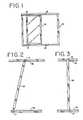
- FIG. 1is a front elevation of a horizontally slidable sash and frame incorporating the brake shoe assembly device of the present invention
- FIG. 2is a front elevation of a horizontally slidable sash and frame showing installation and removal of the sash;
- FIG. 3is a partial front elevation of the sash and frame utilizing the present invention showing the sash pivoted perpendicular to the frame;
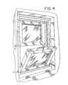
- FIG. 4is a front elevation of a double-hung vertically sliding window assembly incorporating the device of the present invention
- FIG. 5is an exploded perspective view of a brake shoe assembly, pivot bar and a brake shoe track
- FIG. 6is an exploded perspective view of the brake shoe assembly and pivot bar as seen from below, with a sash shown in phantom lines;
- FIG. 7is an exploded view of the brake shoe assembly
- FIG. 8is a perspective view of a slide block of the brake shoe assembly
- FIG. 9is a perspective view of radial brake members of the brake shoe assembly.
- FIG. 10is a perspective view of a cam mechanism of the brake shoe assembly
- FIG. 11is a plan view of the brake shoe assembly in a shoe track wherein the sash, depicted by phantom lines, is in a normally planar position;
- FIG. 12is a plan view of the brake shoe assembly with the sash, depicted by phantom lines, pivoted 90° out of the plane of the frame, showing the brake shoe assembly in an actuated position;
- FIG. 13is a vertical cross section taken through line 13 — 13 of FIG. 11 showing the brake shoe assembly in a non-actuated position and also showing additional sash frame construction;
- FIG. 14is a partial vertical cross section taken through line 14 — 14 of FIG. 12 showing the brake shoe assembly in an actuated position and also showing additional sash frame construction;
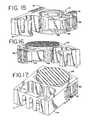
- FIG. 15is a partial cut-away view of the brake shoe with the cam mechanism rotated and showing a radial brake member extending beyond an outer surface of the brake shoe;
- FIG. 16is a partial cut-away of the brake shoe with the cam mechanism rotated and showing the radial brake member not depicted in FIG. 15 extending beyond an outer surface of the brake shoe;
- FIG. 17is a perspective view of the brake shoe showing the radial brake members extended beyond the outer surface of the brake shoe;
- FIG. 18is a partial view of a window assembly depicting the window at its initial stages of pivoting
- FIG. 19is a rear view of the brake shoe assembly
- FIG. 20is a perspective view of the rear of a second preferred embodiment of the brake shoe assembly of the invention.
- FIG. 21is an exploded perspective view of the second preferred embodiment of the brake shoe assembly of the invention.
- FIG. 22is a front plan view of the second preferred embodiment of the brake shoe assembly of the invention.
- FIG. 23is a side view of the second preferred embodiment of the brake shoe assembly of present invention.
- FIG. 24is a perspective view of the rear of the second preferred embodiment of the brake shoe assembly of the present invention showing the radial brake members extended beyond the outer surface of the brake shoe;
- FIG. 25is a front view of the brake shoe assembly of the second preferred embodiment of the present invention.
- FIG. 26is an end view of the brake shoe assembly of the second preferred embodiment of the present invention showing the radial brake members extended beyond the outer surface of the brake shoe;
- FIG. 27is a front elevation view of a third preferred embodiment of the invention.
- FIG. 28is a front elevation view of the embodiment of FIG. 27 showing the cam in a rotated position.
- FIG. 1 of the drawingsthere is shown a slidable window generally designated by numeral 10 and a window frame 12 .
- the window assemblycould also be a door assembly wherein a slidable door is positioned within a door frame.
- Brake shoe assemblies 11are mounted in parallel opposed tracks 16 to provide normal sliding motion of the sash 10 in frame 12 .
- the sash 10is adapted to pivot out of the plane of the frame 12 about a vertical axis through the brake shoe assemblies 11 .
- FIGS. 1-3show a horizontal window assembly
- the inventioncan also be utilized in a vertical window assembly such as the double-hung window assembly shown in FIG. 4 .
- the inventionis not limited to either horizontally or vertically sliding sashes, but also relates to any other sliding member within a frame.
- FIG. 5a partial perspective view of the frame 12 is shown having a pair of integral parallel tracks 16 formed therein into one of which a slider body 14 may be slidably mounted.
- the frame 12may be formed of aluminum or plastic in an extrusion process or other suitable manufacturing method.
- Significant components of the track 16include an elongated base 18 and a pair of opposed, spaced apart sidewalls 20 substantially parallel to one another and generally perpendicular to the elongated base 18 .
- Each sidewall 20has an inwardly facing shoulder 22 , substantially parallel to the opposed elongated base 18 .
- the brake shoe assembly 11generally includes a slider body 14 , a cam mechanism 40 , and brake members 34 , 35 .
- the slider body 14has outside dimensions contoured to fit within the track 16 as described above.
- Slider body 14preferably is manufactured from a tough material such as nylon.
- the slider body 14has a central opening 28 in proximity to an end 27 .
- the central opening 28extends from a front face of the body 14 to a rear face of the body 14 .
- the end of slider body 14 distal from end 27is adapted to receive insert 21 ( FIG.
- the slider body 14has two pairs of protuberances 45 that are preferably integrally formed with the slider body 14 and extend into the central opening 28 .
- the slider body 14is adapted to accept different inserts 21 at its upper portion.
- the insertsaccommodate different types of balance systems. Different types of balance systems have different connecting structures. Thus, with the use of inserts 21 , a single slider body 14 can accept any of the different balance systems.
- the brake members 34 , 35are generally u-shaped.
- the inner surface 31 of each brake member 34has a centrally located substantially planar or flat surface or portion 47 .
- the flat surface 47confronts the cam mechanism 40 as described in greater detail below.
- Integrally formed in brake members 34are lips 41 .
- Each brake member 34 , 35preferably has a pair of lips 41 at opposite ends.
- Radial brake members 34 , 35are adapted such that lips 41 cooperate with the protrusions 45 as will be described in greater detail below.
- the brake members 34also have outer braking surfaces such as frictional ribbed surfaces 36 .
- the frictional ribs 36can be formed into two groups that extend away from one another, or merely be formed in generally parallel relation. In one preferred embodiment of the invention, the frictional ribs 36 , have serrated ends as shown in FIG. 19 , to further improve their friction engaging properties.
- the cam mechanism 40is adapted to rotate and axially move in the central opening 28 in the slider body 14 .
- the outer surface of the cam 40has two diametrically opposite flats or flat portions 42 and two generally circular portions 57 .
- the cam mechanism 40also has a circular flange 46 preferably integrally formed therewith.
- the flange 46 of the cam mechanism 40has a pair of diametric recesses 48 on a base surface of the flange 46 .
- the recesses 48receive protuberances 38 positioned on the brake members 34 , 35 .
- the flange 46is adapted to fit in close abutment against a shoulder 30 ( FIG. 6 ) of the slider body 14 .
- the cam mechanism 40is further adapted such that flats 42 fit in close abutment with planar surfaces 47 of the brake members 34 , 35 .
- the underside of cam mechanism 40has a plurality of elongated ridges or cam base friction ribs 43 extending across its planar underside.
- slider body 14also includes friction engaging means 50 such as substantially transverse friction ribs 51 extending from a front or upper surface of the slider body 14 .
- the ribs 51slide in close abutment with the track inwardly facing shoulders 22 .
- the ribs 51are comprised of two groups positioned at converging angles with respect to one another. Alternatively, the ribs 51 could be positioned in substantial parallel relation.
- cam mechanism 40includes an elongated axial opening 54 , centrally located, having a rectangular keyway 56 at one side opposing an arcuate surface 58 .
- An upwardly extending pivot means 60 , or pivot member or bar 60 , for joining sash 10 to slider body 14is mounted within the opening 54 of cam mechanism 40 , adapted to fit in close abutment with the keyway 56 .
- the upper extension of the pivot member 60has longitudinal ribs 68 configured to receive mating slotted surface 64 of locking tab 62 .
- pivot means 60is secured to pivot means 60 by a bolt and lock nut (not shown).
- Extension 70 of the pivot means 60is securely fastened to the underside of sash 10 in recess 74 , such as with two screws (not shown) or any other known connection means.
- the pivot bar 60is shown as a separate structure that is releasably connected to the sash 10 and cam mechanism 40 , it is understood that the pivot bar 60 may be integral with the sash 10 . It is further understood that other pivot members 60 could be utilized with the brake shoe 11 .
- a friction pad 76consisting of a plurality of elongated ribs 78 is mounted to the underside of horizontal arm 70 of pivot means 60 via any suitable known attachment means, such that elongated ribs 78 extend from horizontal arm 70 towards the shoe track 16 when the sash 10 is in its slidable position.
- Sash 10has surfaces 80 adjacent to tracks 16 when sash 10 is in its slidable position. Additional friction pads 76 are mounted to surfaces 80 by any known suitable attachment means such that their elongated ribs 78 extend towards the track 16 when sash 10 is in its slidable position.
- window or door sash 10freely slides horizontally or vertically in frame 12 .
- the flat portions 42 of the cam 40are adjacent to the flat portions 47 of brake members 34 and the recesses 48 receive the protrusions 38 of brake members 34 , 35 .
- the brake members 34 , 35 and cam 40are positioned generally within the slider body 14 . This is defined as a free-sliding window or door position, such as shown in FIGS. 11 and 13 .
- the end of the sash distal from the slider body 14is freed from the frame and pivoted outwardly to a position such as shown in FIGS. 3 , 4 , 12 and 14 , by rotation of pivot means 60 and cam mechanism 40 of the slider body 14 .
- the cam 40 and brake members 34 , 35include cooperative structure for converting rotary motion of the cam 40 into radial movement of the brake members 34 , 35 through the side openings 32 , 33 and axial movement of the cam 40 and slider body 14 .
- friction pads 76frictionally engage the adjacent tracks 16 ( FIG.
- cam mechanism 40is rotated causing its substantially circular portions 57 to cooperate with and engage the flat portions 47 of the brake members 34 , 35 laterally displacing radial brake members 34 , 35 through the side openings 32 , 33 whereby the ribbed surfaces 36 are pressed radially outwardly against opposed track sidewalls 20 causing frictional engagement of the same (FIGS. 12 and 14 ).
- This radial movementcan be realized quicker with the embodiment shown in FIGS. 27 and 28 described below.
- the first and second lips 41 on the brake members 34 , 35engage the first and second protuberances 45 (FIG. 19 ).
- This rotation of the cam mechanism 40also substantially concurrently causes axial biasing of cam mechanism 40 and slider body 14 via interaction of the protrusions 38 moving out of the recesses 48 and engaging the base surface of the flange 46 of the cam 40 such as shown in FIGS. 15-17 .
- the friction ribs 51 on the slider body 14are pressed against the inwardly facing shoulders 22
- cam base elongated ribs 43are pressed against track base 18 causing frictional abutment or engagement against the opposed elongated base 18 and shoulders 22 .
- This positionis defined as a locked window or door position.
- the brake assembly 11is locked against the four inner surfaces of the shoe track 16 .
- cam mechanism 40When the sash 10 is rotated back to its slidable position, cam mechanism 40 is rotated such that flats 42 are adjacent to flat portions 47 of brake members 34 , 35 . Protuberances 45 cooperate with lips 41 to provide a resilient biasing force to assist in retracting the radial brake members 34 , thereby frictionally releasing ribbed surfaces 36 from opposed track sidewalls 20 .
- the recesses 48again receive camming protrusions 38 thereby frictionally releasing frictional ribs 51 from inwardly facing shoulders 22 and cam base ridges 43 from the elongated base 18 .
- the brake assembly 11is returned to a free sliding position allowing the slider body 14 to slide within track 16 .
- sash installation and removalare facilitated by the device of the invention.
- Removal of locking tab 62loosens pivot means 60 in the cam mechanism 40 so that the cam mechanism 40 frees the frictional engagement of the four way braking of the subject invention, such that the sash can be tilted when perpendicular to frame 16 to the position shown in FIG. 2 , for removal from the frame.
- the procedureis reversed for installation of a sash, with locking tab 62 inserted once the sash is positioned perpendicular to tracks 16 of frame 12 .
- FIGS. 20-26A second preferred embodiment of the present invention is depicted in FIGS. 20-26 . Elements of this second embodiment that are similar in structure and function to corresponding elements of the first described embodiment will be referred to with identical reference numerals.
- the brake shoe assembly 11utilizes an integral brake shoe element.
- the radial or lateral brake members 34are connected by a first, upper resiliently flexible member 239 and a second, or lower resiliently flexible member 241 .
- the integral brake elementconsisting of brake members 34 , 35 and flexible members 239 , 241 is mounted in the slider body 14 such that the brake members 34 are slidably located in the side openings 32 , 33 and such that the flexible members 239 , 241 are located within the central opening 28 .
- the cam mechanism 40is mounted within the central opening 28 such that the flexible members 239 generally surround the cam mechanism 40 .
- the window or door sash 10freely slides horizontally or vertically in the frame 12 . If it is desired to pivot sash 10 out of the plane of the frame 12 , such as for washing the rear side of the sash glass, the end of the sash distal from the slider bodies, is freed from the frame and pivoted outwardly away from the frame by rotation of the pivot bar 60 and cam mechanism 40 of the upper and lower slider bodies 14 connected thereto.
- friction pads 76frictionally engage outer surfaces of their adjacent tracks 16 to provide initial braking of any sliding movement of slider bodies 14 prior to full engagement of the four-way braking of the present invention.
- the cam mechanism 40is rotated causing its substantially cylindrical surface 57 to cooperate with the inner surface 31 of the brake members 34 , 35 to laterally displace the brake members 34 , 35 whereby ribbed surfaces 36 are pressed radially outwardly against opposed track sidewalls 20 causing frictional engagement of the same.
- the flexible members 239 , 241flex to allow radial movement of the brake members 34 , 35 .
- Rotation of the cam mechanism 40also substantially concurrently causes axial biasing of the slider body 14 and cam mechanism 40 via interaction of the protrusions 38 leaving the recesses 48 on the cam flange 46 and engaging the base surface of the cam flange 46 whereby frictional ribs 51 are pressed upwardly against inwardly facing shoulders 22 , and ridges 43 of the cam 40 are pressed against the elongated base 18 causing frictional engagement of the opposed elongated base 18 and shoulders 22 .
- cam mechanism 40When the sash 10 is rotated back to its slidable position, cam mechanism 40 is rotated such that flats 42 are adjacent to planar surfaces allowing the resiliently flexible members 239 , 241 to bias the radial brake members 34 , 35 back through the side openings 32 , 33 to thereby release the ribbed surfaces 36 of the brake members 34 , 35 from the opposed track sidewalls 20 .
- the recesses 48again receive camming protrusions 38 thereby releasing frictional ribs 51 from the inwardly facing shoulders 22 and cam ridges 43 from the track base 18 , allowing slider body 14 to slide within the track 16 .
- the flexible members 239 , 241provide a resilient biasing force to assist in retracting the brake members 34 , 35 back through the side openings 32 , 33 .
- FIGS. 27 and 28A third preferred embodiment of the present invention is depicted in FIGS. 27 and 28 .
- the brake members 34 , 35 of the first preferred embodimentare connected by a single resilient flexible membrane or member 339 to provide an integral brake element.
- the brake members 34 , 35are slidably mounted within respective side openings 32 , 33 .
- the planar surfaces 47 of the brake members 34 , 35each have a radial brake member depression 340 formed therein. In a most preferred embodiment, the depressions 340 are formed at substantially a midportion of the planar surface 47 .
- the cam mechanism 40has a radial protrusion 341 formed on each flat surface 42 .
- the radial protrusion 341is formed at substantially a midportion of the flat surface 42 .
- the cam mechanism 40is mounted in the central opening 28 such that the flexible member 339 extends around the cam mechanism 40 .
- the radial protrusions 341are received by the depressions 40 on the brake members 34 , 35 .
- the freely-slidable window position of the third embodimentis defined as that position wherein the cam flats 42 abut the flat portions 47 of brake members 34 , 35 , depressions 340 receive the cam radial protuberances 341 and cam flange recesses 48 receive brake member protrusions 38 .
- the cam radial protuberances 341leave the depressions 340 and engage the flat surfaces 47 of the brake members 34 , 35 to bias the brake members 34 , 35 for radial movement, thus resulting in frictional engagement of frictional ribbed surfaces 36 with opposed side walls 20 of track 16 .
- the position of the cam radial protrusions 341 and depressions 340 on the brake members 34 , 35provide extremely quick movement of the brake members 34 , 35 upon rotation of the cam 40 .
- radial brakingcan be realized upon 10 degrees of rotation of the cam 40 .
- maximum radial brakingis accomplished upon as little as 5 degrees of rotation of the cam 40 .
- maximum brakingis not accomplished until 30-90 degrees of rotation of the cam member.
- the braking forcewas reduced if the cam was rotated greater than 90 degrees because of the flat surfaces on opposite sides of the cam.
- resilient flexible member 339Upon rotation of the cam 40 back to its freely-slidable window position, resilient flexible member 339 provides a resilient biasing force to assist in retracting the brake members 34 , 35 to their freely-slidable window position wherein the frictional ribbed surfaces 36 of the brake members 34 , 35 are released from the opposed side walls 20 .
- camming feature of the third embodimentrepresented by depression 340 and protuberance 341
- the pairs of camming surfaces described hereincan be respectively reserved.
- brake members 34 , 35have a protrusion 38 located on their rear surface and the cam flange 46 has a corresponding recess 48 . It is possible to reverse these surfaces and place protrusion 38 on the cam flange 46 and the recess 38 on the brake members 34 .
- all the features of the several embodiments described hereincan be combined as desired to achieve the desired results.
- the present inventionprovides a number of important advantages.
- the four-way braking described aboveresults in much more secure braking, which is more quickly realized, than that presently available in the prior art.
- Window sashes and doorscan be pivoted out of the plane of a frame, such as for washing, while safely restrained in the frame. Furthermore, by pivoting the window as little as 5 degrees, brake movement and frictional abutment of the braking surfaces with the shoe track can be commenced and accomplished. If desired, the sash can be easily removed from the frame by removal of a locking tab.
- the connecting portion of the pivot means for joining the sash to the sliding mechanismis hidden from access by intruders and can be detached from the sash only when the sash is removed from the frame.
- the pivoting and sliding deviceis simple in design and reliable and trouble-free in operation.
- the frictional ribs on the slider body 14 , cam mechanism 40 and brake members 34provide increased frictional properties.
- the friction pad 76provides initial braking when the sash or door is pivoted.
- the structure and position of the cooperating cam surfaces between the cam 40 and brake members 34 , 35allow for substantially simultaneous, or concurrent movement of the slider body 14 , brake members 34 , 35 , and cam 40 to achieve substantially simultaneous, or concurrent four-way locking against the four inner faces of the track 16 more quickly.
Landscapes
- Engineering & Computer Science (AREA)
- Mechanical Engineering (AREA)
- Braking Arrangements (AREA)
- Wing Frames And Configurations (AREA)
Abstract
Description
Claims (27)
Priority Applications (3)
| Application Number | Priority Date | Filing Date | Title |
|---|---|---|---|
| US10/366,753US6915609B2 (en) | 2001-02-09 | 2003-02-14 | Brake shoe for sash window or door assembly |
| US11/116,865US7194839B2 (en) | 2001-02-09 | 2005-04-28 | Brake shoe for sash window or door assembly |
| US11/685,002US20070151157A1 (en) | 2001-02-09 | 2007-03-12 | Brake Shoe For Sash Window Or Door Assembly |
Applications Claiming Priority (2)
| Application Number | Priority Date | Filing Date | Title |
|---|---|---|---|
| US09/780,917US6550184B1 (en) | 2001-02-09 | 2001-02-09 | Brake shoe for sash window or door assembly |
| US10/366,753US6915609B2 (en) | 2001-02-09 | 2003-02-14 | Brake shoe for sash window or door assembly |
Related Parent Applications (1)
| Application Number | Title | Priority Date | Filing Date |
|---|---|---|---|
| US09/780,917ContinuationUS6550184B1 (en) | 2001-02-09 | 2001-02-09 | Brake shoe for sash window or door assembly |
Related Child Applications (1)
| Application Number | Title | Priority Date | Filing Date |
|---|---|---|---|
| US11/116,865ContinuationUS7194839B2 (en) | 2001-02-09 | 2005-04-28 | Brake shoe for sash window or door assembly |
Publications (2)
| Publication Number | Publication Date |
|---|---|
| US20030121207A1 US20030121207A1 (en) | 2003-07-03 |
| US6915609B2true US6915609B2 (en) | 2005-07-12 |
Family
ID=25121085
Family Applications (4)
| Application Number | Title | Priority Date | Filing Date |
|---|---|---|---|
| US09/780,917Expired - LifetimeUS6550184B1 (en) | 2001-02-09 | 2001-02-09 | Brake shoe for sash window or door assembly |
| US10/366,753Expired - LifetimeUS6915609B2 (en) | 2001-02-09 | 2003-02-14 | Brake shoe for sash window or door assembly |
| US11/116,865Expired - LifetimeUS7194839B2 (en) | 2001-02-09 | 2005-04-28 | Brake shoe for sash window or door assembly |
| US11/685,002AbandonedUS20070151157A1 (en) | 2001-02-09 | 2007-03-12 | Brake Shoe For Sash Window Or Door Assembly |
Family Applications Before (1)
| Application Number | Title | Priority Date | Filing Date |
|---|---|---|---|
| US09/780,917Expired - LifetimeUS6550184B1 (en) | 2001-02-09 | 2001-02-09 | Brake shoe for sash window or door assembly |
Family Applications After (2)
| Application Number | Title | Priority Date | Filing Date |
|---|---|---|---|
| US11/116,865Expired - LifetimeUS7194839B2 (en) | 2001-02-09 | 2005-04-28 | Brake shoe for sash window or door assembly |
| US11/685,002AbandonedUS20070151157A1 (en) | 2001-02-09 | 2007-03-12 | Brake Shoe For Sash Window Or Door Assembly |
Country Status (4)
| Country | Link |
|---|---|
| US (4) | US6550184B1 (en) |
| CA (1) | CA2351287C (en) |
| GB (1) | GB2372531B (en) |
| MX (1) | MXPA01006694A (en) |
Cited By (7)
| Publication number | Priority date | Publication date | Assignee | Title |
|---|---|---|---|---|
| US20060170265A1 (en)* | 2005-02-01 | 2006-08-03 | B E Aerospace, Inc. | Cam lock for vehicle seating |
| US20060230682A1 (en)* | 2005-04-14 | 2006-10-19 | S.I.L. Plastic Sales & Supplies Inc. | Sliding shoe for a window frame |
| US20070011961A1 (en)* | 2005-06-24 | 2007-01-18 | Annes Jason L | Connector for sash window frame members |
| US20070151157A1 (en)* | 2001-02-09 | 2007-07-05 | Newell Operating Company | Brake Shoe For Sash Window Or Door Assembly |
| US20090094898A1 (en)* | 2007-10-15 | 2009-04-16 | Caldwell Manufacturing Company | Assembly of Cam-actuated Brake in Locking Shoe for Tilt Sash |
| US20100275521A1 (en)* | 2009-04-29 | 2010-11-04 | Vision Extrusions Limited | Window sash frame |
| US20120126548A1 (en)* | 2010-11-23 | 2012-05-24 | Xiao Lu Zhuo | Retractable noise reduction locking shoe assembly for windows or doors |
Families Citing this family (29)
| Publication number | Priority date | Publication date | Assignee | Title |
|---|---|---|---|---|
| US7475026B2 (en)* | 2002-12-06 | 2009-01-06 | Dell Products L.P. | Method for information handling system consumables automated ordering |
| US20040206003A1 (en)* | 2003-04-18 | 2004-10-21 | Kunz John R. | Window sash counterbalance and position locking system for a tilt-in window |
| US7197849B2 (en)* | 2003-07-18 | 2007-04-03 | Vision Industries Group, Inc. | Balance shoe for tilt windows |
| US6990710B2 (en)* | 2003-11-05 | 2006-01-31 | Kunz John R | Counterbalance system for a tilt-in window having an improved shoe assembly and anchor mount |
| US20050193631A1 (en)* | 2004-03-08 | 2005-09-08 | Gary Marshik | Balance shoe for tilt-in window sashes |
| JP2005346610A (en)* | 2004-06-07 | 2005-12-15 | Hitachi Ltd | Storage system and method for taking and using snapshots |
| US8371068B1 (en)* | 2005-03-07 | 2013-02-12 | John R. Kunz | System and method for improving the wear life of a brake shoe in the counterbalance system of a tilt-in window |
| US20090064589A1 (en)* | 2007-09-12 | 2009-03-12 | Newell Operating Company | Brake Shoe Assembly For Sash Window Assembly |
| GB2458706B (en)* | 2008-03-28 | 2012-05-23 | Mighton Products Ltd | Slide shoe for a sash window |
| NL1036550C2 (en)* | 2009-02-11 | 2010-08-12 | Westerbildt B V | WALL COMPOSED FROM A NUMBER OF VERTICAL PANELS THAT ARE SCREWABLE AND SWIVELABLE WITH REGARD TO AN ABOVE AND UNDER GUIDE. |
| US20100300003A1 (en)* | 2009-05-28 | 2010-12-02 | Estell Goode | Door system with interchangeable panel inserts |
| IT1397484B1 (en)* | 2009-12-21 | 2013-01-16 | Metalglas S R L | PACKABLE MOBILE PANEL SYSTEM. |
| US20120311934A1 (en)* | 2011-06-07 | 2012-12-13 | Steven Robert Abramson | Draft Guard |
| US10107022B2 (en) | 2011-06-07 | 2018-10-23 | Henniges Automotive Schlegel Canada, Inc. | Draft guard for window assembly having seals and integral fins |
| US20140208655A1 (en)* | 2013-01-25 | 2014-07-31 | Amesbury Group, Inc. | Sash cam for side load window balance system |
| US9097061B1 (en) | 2013-03-14 | 2015-08-04 | Barry G. Lawrence | Window sash pivot bar |
| US9316043B1 (en)* | 2013-03-14 | 2016-04-19 | Barry G. Lawrence | Window frame and method |
| CN203308300U (en)* | 2013-05-13 | 2013-11-27 | 佛山市爱迪尔卫浴有限公司 | Door assembly |
| CN104975785B (en)* | 2014-04-01 | 2017-02-08 | 佛山市理想卫浴有限公司 | Fast mounting and adjusting shower door assembly |
| CN104234558A (en)* | 2014-08-01 | 2014-12-24 | 浙江瑞明节能科技股份有限公司 | Door and window sash positioning device used for sliding door and window |
| GB2543758A (en)* | 2015-10-23 | 2017-05-03 | Mighton Products Ltd | Sash window pivot shoe |
| US10604930B2 (en)* | 2017-02-15 | 2020-03-31 | Hunter Douglas Inc. | Friction adjustment member for architectural covering |
| US10822863B2 (en) | 2018-05-02 | 2020-11-03 | Pella Corporation | Sliding fenestration unit with coplanar panels |
| CA3066592C (en)* | 2019-01-09 | 2023-06-13 | Pella Corporation | Slide and pivot fenestration unit |
| US11549293B1 (en)* | 2019-11-12 | 2023-01-10 | Barry G. Lawrence | Threaded pivot bar and method |
| US11536082B2 (en) | 2020-09-18 | 2022-12-27 | Jeld-Wen, Inc. | Pivot bar for sash windows |
| GB2628213B (en)* | 2020-12-22 | 2025-06-04 | Assa Abloy Ltd | Pivot shoe |
| DE102022209510A1 (en)* | 2022-09-12 | 2024-03-14 | Geze Gmbh | Fitting for a sliding door and sliding door |
| US12416189B1 (en) | 2024-03-13 | 2025-09-16 | Pella Corporation | Fenestration system with head slide |
Citations (62)
| Publication number | Priority date | Publication date | Assignee | Title |
|---|---|---|---|---|
| US1226145A (en) | 1916-01-20 | 1917-05-15 | Emanuel P Summerfield | Window. |
| US1272039A (en) | 1914-07-25 | 1918-07-09 | Bernard Hausmann | Window. |
| US1873066A (en) | 1929-04-09 | 1932-08-23 | John R Stewart | Window sash mounting |
| US2308621A (en) | 1940-10-11 | 1943-01-19 | Joseph I Levyn | Window structure |
| US2500849A (en) | 1946-01-10 | 1950-03-14 | Everett S Menns | Window construction |
| US3012292A (en) | 1959-02-11 | 1961-12-12 | Malta Mfg Company | Removable window with sash counterbalance locking device |
| US3108335A (en) | 1960-11-29 | 1963-10-29 | Sr Fred C Osten | Removable sash window construction |
| US3118190A (en) | 1961-12-05 | 1964-01-21 | Gordon W Love | Tiltably-removable automaticallylocking sash window |
| US3146501A (en) | 1962-09-24 | 1964-09-01 | Lowell E Peters | Side camming balance spring lock |
| US3157917A (en) | 1962-09-20 | 1964-11-24 | Lowell E Peters | Balance spring mechanism |
| US3197819A (en) | 1963-03-25 | 1965-08-03 | Donald M Trout | Self-locking automatically-releasing sash balance for removable sash windows |
| US3348335A (en) | 1965-12-13 | 1967-10-24 | Mauro Anthony | Pivotable sash window |
| US3399490A (en) | 1966-08-04 | 1968-09-03 | Weatherproof Products Corp | Tilt-out sash window |
| US3429071A (en) | 1967-04-26 | 1969-02-25 | James C Wilborn & Sons Inc | Sash lock for removable sash windows |
| US3434236A (en) | 1967-06-07 | 1969-03-25 | Kassl Window Co Inc | Sash lock |
| US3462882A (en) | 1967-04-27 | 1969-08-26 | Anderson Mfg Co V E | Window structure |
| US3466803A (en) | 1968-05-28 | 1969-09-16 | Gen Motors Corp | Guide arrangement |
| US3789549A (en) | 1972-05-30 | 1974-02-05 | Rodman Ind Inc | Rotatable locking supports for sashes of windows |
| US3844066A (en) | 1973-07-13 | 1974-10-29 | Caldwell Mfg Co | Tiltably-removable automatically-locking window sash |
| US4068406A (en) | 1976-08-19 | 1978-01-17 | Jim Walter Corporation | Side camming balance spring lock |
| US4222201A (en) | 1978-11-06 | 1980-09-16 | Air Master Corporation | Sliding, pivoting window |
| US4227345A (en) | 1979-01-26 | 1980-10-14 | Durham Jr Robert C | Tilt-lock slide for window sash |
| US4337597A (en) | 1980-04-07 | 1982-07-06 | Struckmeyer Ernest F | Sliding window construction having pivotal characteristic to facilitate cleaning both sides of the window |
| US4452012A (en) | 1982-08-09 | 1984-06-05 | Caldwell Manufacturing Company | Pivot shoe for sash balance |
| US4506478A (en) | 1979-06-21 | 1985-03-26 | V. E. Anderson Mfg. Co. | Window structure |
| US4559739A (en) | 1983-11-28 | 1985-12-24 | Thermal-Barrier Products, Inc. | Stabilized pivotable window |
| US4590708A (en) | 1985-03-01 | 1986-05-27 | Allen-Stevens Corp. | Arrangement for tiltably mounting a window sash |
| US4610108A (en) | 1984-12-20 | 1986-09-09 | Marshik Gary J | Balance spring locking slide block for tilt-out windows |
| US4644691A (en) | 1985-06-11 | 1987-02-24 | Amerock Corporation | Apparatus for mounting and stabilizing a tiltable window sash |
| US4683675A (en) | 1985-11-07 | 1987-08-04 | Illinois Tool Works Inc. | Shoe for a closure |
| US4683676A (en) | 1985-11-20 | 1987-08-04 | Product Design & Development, Inc. | Tilt window balance shoe assembly |
| US4718194A (en) | 1986-10-10 | 1988-01-12 | Balance Systems, Inc. | Window sash support and movement lock assembly |
| US4813180A (en) | 1987-07-09 | 1989-03-21 | Harvey Industries | Double-hung window pivot |
| US4854077A (en) | 1988-10-13 | 1989-08-08 | Schlegel Corporation | Fail-safe tip-lock shoe |
| US4888915A (en) | 1988-09-14 | 1989-12-26 | Shaul Goldenberg | Tilt slider |
| US4922657A (en) | 1989-09-08 | 1990-05-08 | Eastern Balance Corporation | Locking slide for tilt-out window balance system |
| US4958462A (en) | 1989-06-05 | 1990-09-25 | Cross Rex D | Locking pivot shoe |
| US5027557A (en) | 1989-08-30 | 1991-07-02 | Intek Weatherseal Products, Inc. | Sound silenced window frame jamb liner sash guide pocket |
| US5058321A (en) | 1991-04-05 | 1991-10-22 | Plastmo Ltd. | Pivoting & locking device for a window or door sash |
| US5127192A (en) | 1991-08-07 | 1992-07-07 | Cross Rex D | Pivot shoe for removable sash |
| US5210976A (en) | 1991-08-16 | 1993-05-18 | Vinyl Concepts Incorporated | Window balance assembly |
| US5237775A (en) | 1990-09-11 | 1993-08-24 | L.B. Plastics Limited | Sliding mechanism for window constructions |
| US5251401A (en) | 1991-10-02 | 1993-10-12 | Ashland Products, Inc. | Pivot corner for a sash window |
| US5301467A (en) | 1992-06-24 | 1994-04-12 | Andersen Corporation | Locking slide block |
| US5371971A (en) | 1993-05-04 | 1994-12-13 | Ashland Products, Inc. | Sash balance brake and pivot pin assembly |
| US5377384A (en) | 1993-04-05 | 1995-01-03 | Riegelman; Harry M. | Locking pivot shoe |
| US5383303A (en) | 1991-12-04 | 1995-01-24 | Nakanishi Engineering Co., Ltd. | Window |
| US5414960A (en) | 1994-02-04 | 1995-05-16 | O'donnell; Richard H. | Window & door sash frictional locking device |
| US5632117A (en) | 1995-01-13 | 1997-05-27 | Ashland Prod Inc | Sash balance brake assembly |
| US5661927A (en) | 1996-03-06 | 1997-09-02 | Ashland Products, Inc. | Sliding counterbalance assembly for a sash window |
| US5697188A (en) | 1995-12-08 | 1997-12-16 | Ken Fullick | Window sash balance shoe with friction adjust mechanism |
| US5704165A (en) | 1996-07-19 | 1998-01-06 | Csb Enterprises, Inc. | Pivotable window sash assembly |
| US5802767A (en) | 1996-12-16 | 1998-09-08 | Csb Enterprises, Inc. | Balance shoe having a recess for accommodating a weld flash of a hollow window frame |
| US5829196A (en) | 1996-05-29 | 1998-11-03 | Ro-Mai Industries, Inc. | Window balance brake shoe and pivot assembly |
| US5927014A (en) | 1988-12-21 | 1999-07-27 | Shaul Goldenberg | Double locking pivot shoe |
| US5943822A (en) | 1996-12-16 | 1999-08-31 | Csb Enterprises, Inc. | Balanceshoe having a recess for accommodating a weld flash of a hollow window frame |
| US6032417A (en) | 1997-04-11 | 2000-03-07 | Caldwell Manufacturing Company | Corner locking carrier shoe for tilt sash |
| US6058653A (en) | 1996-07-19 | 2000-05-09 | Csb Enterprise, Inc. | Pivotable window sash assembly |
| US6119398A (en) | 1998-11-05 | 2000-09-19 | Yates, Jr.; H. Dale | Tilt window balance shoe assembly with three directional locking |
| US6161335A (en) | 1999-12-02 | 2000-12-19 | Csb Enterprise, Inc. | Balance shoe for reducing the size of a pivotable window sash assembly |
| US6550184B1 (en)* | 2001-02-09 | 2003-04-22 | Ashland Products, Inc. | Brake shoe for sash window or door assembly |
| US6679000B2 (en)* | 2001-01-12 | 2004-01-20 | Amesbury Group, Inc. | Snap lock balance shoe and system for a pivotable window |
Family Cites Families (2)
| Publication number | Priority date | Publication date | Assignee | Title |
|---|---|---|---|---|
| US5243783A (en)* | 1992-06-24 | 1993-09-14 | Andersen Corporation | Locking slide block |
| US6886295B2 (en)* | 2002-02-01 | 2005-05-03 | Ashland Products, Inc. | Brake shoe with spring brake member |
- 2001
- 2001-02-09USUS09/780,917patent/US6550184B1/ennot_activeExpired - Lifetime
- 2001-06-22CACA002351287Apatent/CA2351287C/ennot_activeExpired - Lifetime
- 2001-06-28MXMXPA01006694Apatent/MXPA01006694A/enunknown
- 2002
- 2002-02-06GBGB0202703Apatent/GB2372531B/ennot_activeExpired - Fee Related
- 2003
- 2003-02-14USUS10/366,753patent/US6915609B2/ennot_activeExpired - Lifetime
- 2005
- 2005-04-28USUS11/116,865patent/US7194839B2/ennot_activeExpired - Lifetime
- 2007
- 2007-03-12USUS11/685,002patent/US20070151157A1/ennot_activeAbandoned
Patent Citations (64)
| Publication number | Priority date | Publication date | Assignee | Title |
|---|---|---|---|---|
| US1272039A (en) | 1914-07-25 | 1918-07-09 | Bernard Hausmann | Window. |
| US1226145A (en) | 1916-01-20 | 1917-05-15 | Emanuel P Summerfield | Window. |
| US1873066A (en) | 1929-04-09 | 1932-08-23 | John R Stewart | Window sash mounting |
| US2308621A (en) | 1940-10-11 | 1943-01-19 | Joseph I Levyn | Window structure |
| US2500849A (en) | 1946-01-10 | 1950-03-14 | Everett S Menns | Window construction |
| US3012292A (en) | 1959-02-11 | 1961-12-12 | Malta Mfg Company | Removable window with sash counterbalance locking device |
| US3108335A (en) | 1960-11-29 | 1963-10-29 | Sr Fred C Osten | Removable sash window construction |
| US3118190A (en) | 1961-12-05 | 1964-01-21 | Gordon W Love | Tiltably-removable automaticallylocking sash window |
| US3157917A (en) | 1962-09-20 | 1964-11-24 | Lowell E Peters | Balance spring mechanism |
| US3146501A (en) | 1962-09-24 | 1964-09-01 | Lowell E Peters | Side camming balance spring lock |
| US3197819A (en) | 1963-03-25 | 1965-08-03 | Donald M Trout | Self-locking automatically-releasing sash balance for removable sash windows |
| US3348335A (en) | 1965-12-13 | 1967-10-24 | Mauro Anthony | Pivotable sash window |
| US3399490A (en) | 1966-08-04 | 1968-09-03 | Weatherproof Products Corp | Tilt-out sash window |
| US3429071A (en) | 1967-04-26 | 1969-02-25 | James C Wilborn & Sons Inc | Sash lock for removable sash windows |
| US3462882A (en) | 1967-04-27 | 1969-08-26 | Anderson Mfg Co V E | Window structure |
| US3434236A (en) | 1967-06-07 | 1969-03-25 | Kassl Window Co Inc | Sash lock |
| US3466803A (en) | 1968-05-28 | 1969-09-16 | Gen Motors Corp | Guide arrangement |
| US3789549A (en) | 1972-05-30 | 1974-02-05 | Rodman Ind Inc | Rotatable locking supports for sashes of windows |
| US3844066A (en) | 1973-07-13 | 1974-10-29 | Caldwell Mfg Co | Tiltably-removable automatically-locking window sash |
| US4068406A (en) | 1976-08-19 | 1978-01-17 | Jim Walter Corporation | Side camming balance spring lock |
| US4222201A (en) | 1978-11-06 | 1980-09-16 | Air Master Corporation | Sliding, pivoting window |
| US4227345A (en) | 1979-01-26 | 1980-10-14 | Durham Jr Robert C | Tilt-lock slide for window sash |
| US4506478A (en) | 1979-06-21 | 1985-03-26 | V. E. Anderson Mfg. Co. | Window structure |
| US4337597A (en) | 1980-04-07 | 1982-07-06 | Struckmeyer Ernest F | Sliding window construction having pivotal characteristic to facilitate cleaning both sides of the window |
| US4452012A (en) | 1982-08-09 | 1984-06-05 | Caldwell Manufacturing Company | Pivot shoe for sash balance |
| US4559739A (en) | 1983-11-28 | 1985-12-24 | Thermal-Barrier Products, Inc. | Stabilized pivotable window |
| US4610108A (en) | 1984-12-20 | 1986-09-09 | Marshik Gary J | Balance spring locking slide block for tilt-out windows |
| US4590708A (en) | 1985-03-01 | 1986-05-27 | Allen-Stevens Corp. | Arrangement for tiltably mounting a window sash |
| US4644691A (en) | 1985-06-11 | 1987-02-24 | Amerock Corporation | Apparatus for mounting and stabilizing a tiltable window sash |
| US4683675A (en) | 1985-11-07 | 1987-08-04 | Illinois Tool Works Inc. | Shoe for a closure |
| US4683676A (en) | 1985-11-20 | 1987-08-04 | Product Design & Development, Inc. | Tilt window balance shoe assembly |
| US4718194A (en) | 1986-10-10 | 1988-01-12 | Balance Systems, Inc. | Window sash support and movement lock assembly |
| US4813180A (en) | 1987-07-09 | 1989-03-21 | Harvey Industries | Double-hung window pivot |
| US4888915A (en) | 1988-09-14 | 1989-12-26 | Shaul Goldenberg | Tilt slider |
| US5168665A (en) | 1988-09-14 | 1992-12-08 | Shaul Goldenberg | Tilt slider |
| US4854077A (en) | 1988-10-13 | 1989-08-08 | Schlegel Corporation | Fail-safe tip-lock shoe |
| US5927014A (en) | 1988-12-21 | 1999-07-27 | Shaul Goldenberg | Double locking pivot shoe |
| US4958462A (en) | 1989-06-05 | 1990-09-25 | Cross Rex D | Locking pivot shoe |
| US5027557A (en) | 1989-08-30 | 1991-07-02 | Intek Weatherseal Products, Inc. | Sound silenced window frame jamb liner sash guide pocket |
| US4922657A (en) | 1989-09-08 | 1990-05-08 | Eastern Balance Corporation | Locking slide for tilt-out window balance system |
| US5237775A (en) | 1990-09-11 | 1993-08-24 | L.B. Plastics Limited | Sliding mechanism for window constructions |
| US5058321A (en) | 1991-04-05 | 1991-10-22 | Plastmo Ltd. | Pivoting & locking device for a window or door sash |
| US5127192A (en) | 1991-08-07 | 1992-07-07 | Cross Rex D | Pivot shoe for removable sash |
| US5210976A (en) | 1991-08-16 | 1993-05-18 | Vinyl Concepts Incorporated | Window balance assembly |
| US5251401A (en) | 1991-10-02 | 1993-10-12 | Ashland Products, Inc. | Pivot corner for a sash window |
| US5383303A (en) | 1991-12-04 | 1995-01-24 | Nakanishi Engineering Co., Ltd. | Window |
| US5301467A (en) | 1992-06-24 | 1994-04-12 | Andersen Corporation | Locking slide block |
| US5377384A (en) | 1993-04-05 | 1995-01-03 | Riegelman; Harry M. | Locking pivot shoe |
| US5371971A (en) | 1993-05-04 | 1994-12-13 | Ashland Products, Inc. | Sash balance brake and pivot pin assembly |
| US5414960A (en) | 1994-02-04 | 1995-05-16 | O'donnell; Richard H. | Window & door sash frictional locking device |
| US5806243A (en) | 1995-01-13 | 1998-09-15 | Ashland Products, Inc. | Sash balance brake assembly |
| US5632117A (en) | 1995-01-13 | 1997-05-27 | Ashland Prod Inc | Sash balance brake assembly |
| US5697188A (en) | 1995-12-08 | 1997-12-16 | Ken Fullick | Window sash balance shoe with friction adjust mechanism |
| US5661927A (en) | 1996-03-06 | 1997-09-02 | Ashland Products, Inc. | Sliding counterbalance assembly for a sash window |
| US5829196A (en) | 1996-05-29 | 1998-11-03 | Ro-Mai Industries, Inc. | Window balance brake shoe and pivot assembly |
| US5704165A (en) | 1996-07-19 | 1998-01-06 | Csb Enterprises, Inc. | Pivotable window sash assembly |
| US6058653A (en) | 1996-07-19 | 2000-05-09 | Csb Enterprise, Inc. | Pivotable window sash assembly |
| US5802767A (en) | 1996-12-16 | 1998-09-08 | Csb Enterprises, Inc. | Balance shoe having a recess for accommodating a weld flash of a hollow window frame |
| US5943822A (en) | 1996-12-16 | 1999-08-31 | Csb Enterprises, Inc. | Balanceshoe having a recess for accommodating a weld flash of a hollow window frame |
| US6032417A (en) | 1997-04-11 | 2000-03-07 | Caldwell Manufacturing Company | Corner locking carrier shoe for tilt sash |
| US6119398A (en) | 1998-11-05 | 2000-09-19 | Yates, Jr.; H. Dale | Tilt window balance shoe assembly with three directional locking |
| US6161335A (en) | 1999-12-02 | 2000-12-19 | Csb Enterprise, Inc. | Balance shoe for reducing the size of a pivotable window sash assembly |
| US6679000B2 (en)* | 2001-01-12 | 2004-01-20 | Amesbury Group, Inc. | Snap lock balance shoe and system for a pivotable window |
| US6550184B1 (en)* | 2001-02-09 | 2003-04-22 | Ashland Products, Inc. | Brake shoe for sash window or door assembly |
Cited By (10)
| Publication number | Priority date | Publication date | Assignee | Title |
|---|---|---|---|---|
| US20070151157A1 (en)* | 2001-02-09 | 2007-07-05 | Newell Operating Company | Brake Shoe For Sash Window Or Door Assembly |
| US20060170265A1 (en)* | 2005-02-01 | 2006-08-03 | B E Aerospace, Inc. | Cam lock for vehicle seating |
| US7261378B2 (en)* | 2005-02-01 | 2007-08-28 | Be Aerospace, Inc. | Cam lock for vehicle seating |
| US20060230682A1 (en)* | 2005-04-14 | 2006-10-19 | S.I.L. Plastic Sales & Supplies Inc. | Sliding shoe for a window frame |
| US7726073B2 (en)* | 2005-04-14 | 2010-06-01 | S.I.L. Plastic Sales & Supplies Inc. | Sliding shoe for a window frame |
| US20070011961A1 (en)* | 2005-06-24 | 2007-01-18 | Annes Jason L | Connector for sash window frame members |
| US7628562B2 (en) | 2005-06-24 | 2009-12-08 | Newell Operating Company | Connector for sash window frame members |
| US20090094898A1 (en)* | 2007-10-15 | 2009-04-16 | Caldwell Manufacturing Company | Assembly of Cam-actuated Brake in Locking Shoe for Tilt Sash |
| US20100275521A1 (en)* | 2009-04-29 | 2010-11-04 | Vision Extrusions Limited | Window sash frame |
| US20120126548A1 (en)* | 2010-11-23 | 2012-05-24 | Xiao Lu Zhuo | Retractable noise reduction locking shoe assembly for windows or doors |
Also Published As
| Publication number | Publication date |
|---|---|
| US7194839B2 (en) | 2007-03-27 |
| US20050183340A1 (en) | 2005-08-25 |
| CA2351287A1 (en) | 2002-08-09 |
| GB2372531A (en) | 2002-08-28 |
| US20070151157A1 (en) | 2007-07-05 |
| GB0202703D0 (en) | 2002-03-20 |
| CA2351287C (en) | 2004-09-07 |
| US20030121207A1 (en) | 2003-07-03 |
| GB2372531B (en) | 2004-08-25 |
| MXPA01006694A (en) | 2002-08-19 |
| US6550184B1 (en) | 2003-04-22 |
Similar Documents
| Publication | Publication Date | Title |
|---|---|---|
| US6915609B2 (en) | Brake shoe for sash window or door assembly | |
| CA2141758C (en) | Window and door sash frictional locking device | |
| US6119398A (en) | Tilt window balance shoe assembly with three directional locking | |
| CA2016989C (en) | Locking pivot shoe | |
| US5632117A (en) | Sash balance brake assembly | |
| US5371971A (en) | Sash balance brake and pivot pin assembly | |
| US7013603B2 (en) | Integrated tilt/sash lock assembly | |
| US7946080B2 (en) | Lock assembly | |
| US4364199A (en) | Removable-tilt-out window construction | |
| CA2129616A1 (en) | Snap in latch assembly for windows | |
| US6886295B2 (en) | Brake shoe with spring brake member | |
| US5826765A (en) | Load bar for automobile luggage carrier | |
| US5829802A (en) | Multi-point lock operator for casement window | |
| IE77512B1 (en) | Pivoting and locking device for a window or door sash | |
| JP2003041832A (en) | Latch device | |
| CA2410112A1 (en) | Block and tackle sash balance brake assembly | |
| US3829139A (en) | Lock handle | |
| US3278213A (en) | Partially opening door latch | |
| JPH11324466A (en) | Hinge for stile and folding door for bathroom utilizing the same | |
| CA1259358A (en) | Friction stay arm assembly for a window | |
| EP1718829B9 (en) | Device at a covering element | |
| CA1116205A (en) | Closure latch assembly | |
| CN213980367U (en) | Wind brace and window with same | |
| CN216949870U (en) | A kind of anti-pulling deviation one-way transmission lock box | |
| CN222010078U (en) | Tapered end and have its flexible door rail |
Legal Events
| Date | Code | Title | Description |
|---|---|---|---|
| STCF | Information on status: patent grant | Free format text:PATENTED CASE | |
| AS | Assignment | Owner name:NEWELL OPERATING COMPANY, ILLINOIS Free format text:MERGER;ASSIGNOR:ASHLAND PRODUCTS, INC.;REEL/FRAME:017057/0649 Effective date:20031231 | |
| CC | Certificate of correction | ||
| FPAY | Fee payment | Year of fee payment:4 | |
| FPAY | Fee payment | Year of fee payment:8 | |
| AS | Assignment | Owner name:WILMINGTON TRUST, NATIONAL ASSOCIATION, MINNESOTA Free format text:SECURITY INTEREST;ASSIGNORS:NOVA WILDCAT AMEROCK, LLC;NOVA WILDCAT ASHLAND, LLC;NOVA WILDCAT BUILDING, LLC;AND OTHERS;REEL/FRAME:031550/0358 Effective date:20131022 | |
| AS | Assignment | Owner name:NOVA WILDCAT ASHLAND, LLC, NORTH CAROLINA Free format text:ASSIGNMENT OF ASSIGNORS INTEREST;ASSIGNOR:NEWELL OPERATING COMPANY;REEL/FRAME:031223/0252 Effective date:20130910 | |
| AS | Assignment | Owner name:WELLS FARGO BANK, NATIONAL ASSOCIATION, AS AGENT, Free format text:SECURITY AGREEMENT;ASSIGNORS:NOVA WILDCAT AMEROCK, LLC;NOVA WILDCAT DRAPERY HARDWARE, LLC;NOVA WILDCAT SHUR-LINE, LLC;AND OTHERS;REEL/FRAME:035057/0444 Effective date:20130910 | |
| FPAY | Fee payment | Year of fee payment:12 | |
| AS | Assignment | Owner name:ASHLAND HARDWARE, LLC, TEXAS Free format text:CHANGE OF NAME;ASSIGNOR:NOVA WILDCAT ASHLAND, LLC;REEL/FRAME:047154/0672 Effective date:20180329 | |
| AS | Assignment | Owner name:ASHLAND PRODUCTS, INC., INDIANA Free format text:ASSIGNMENT OF ASSIGNORS INTEREST;ASSIGNORS:O'DONNELL, RICHARD H.;ANNES, JASON L.;SIGNING DATES FROM 20010214 TO 20010223;REEL/FRAME:046362/0436 | |
| AS | Assignment | Owner name:NOVA WILDCAT SHUR-LINE, LLC, NORTH CAROLINA Free format text:RELEASE BY SECURED PARTY;ASSIGNOR:WELLS FARGO BANK, NATIONAL ASSOCIATION, AS AGENT;REEL/FRAME:047223/0567 Effective date:20181012 Owner name:NOVA WILDCAT ASHLAND, LLC, NORTH CAROLINA Free format text:RELEASE BY SECURED PARTY;ASSIGNOR:WELLS FARGO BANK, NATIONAL ASSOCIATION, AS AGENT;REEL/FRAME:047223/0567 Effective date:20181012 Owner name:NOVA WILDCAT AMEROCK, LLC, NORTH CAROLINA Free format text:RELEASE BY SECURED PARTY;ASSIGNOR:WELLS FARGO BANK, NATIONAL ASSOCIATION, AS AGENT;REEL/FRAME:047223/0567 Effective date:20181012 Owner name:NOVA WILDCAT DRAPERY HARDWARE, LLC, NORTH CAROLINA Free format text:RELEASE BY SECURED PARTY;ASSIGNOR:WELLS FARGO BANK, NATIONAL ASSOCIATION, AS AGENT;REEL/FRAME:047223/0567 Effective date:20181012 Owner name:NOVA WILDCAT BULLDOG, LLC, NORTH CAROLINA Free format text:RELEASE BY SECURED PARTY;ASSIGNOR:WELLS FARGO BANK, NATIONAL ASSOCIATION, AS AGENT;REEL/FRAME:047223/0567 Effective date:20181012 |