US6915191B2 - Method and system for detecting when an end of train has passed a point - Google Patents
Method and system for detecting when an end of train has passed a pointDownload PDFInfo
- Publication number
- US6915191B2 US6915191B2US10/440,129US44012903AUS6915191B2US 6915191 B2US6915191 B2US 6915191B2US 44012903 AUS44012903 AUS 44012903AUS 6915191 B2US6915191 B2US 6915191B2
- Authority
- US
- United States
- Prior art keywords
- train
- positioning system
- head
- point
- determining
- Prior art date
- Legal status (The legal status is an assumption and is not a legal conclusion. Google has not performed a legal analysis and makes no representation as to the accuracy of the status listed.)
- Expired - Lifetime, expires
Links
- 238000000034methodMethods0.000titleclaimsabstractdescription52
- 238000000926separation methodMethods0.000claimsdescription10
- 230000000737periodic effectEffects0.000claims8
- 230000003137locomotive effectEffects0.000description8
- 230000001934delayEffects0.000description3
- 230000008901benefitEffects0.000description2
- 238000010586diagramMethods0.000description2
- 230000000007visual effectEffects0.000description2
- 239000004020conductorSubstances0.000description1
- 230000001419dependent effectEffects0.000description1
- 230000010354integrationEffects0.000description1
- 239000003550markerSubstances0.000description1
- 238000012986modificationMethods0.000description1
- 230000004048modificationEffects0.000description1
Images


Classifications
- B—PERFORMING OPERATIONS; TRANSPORTING
- B61—RAILWAYS
- B61L—GUIDING RAILWAY TRAFFIC; ENSURING THE SAFETY OF RAILWAY TRAFFIC
- B61L15/00—Indicators provided on the vehicle or train for signalling purposes
- B61L15/0054—Train integrity supervision, e.g. end-of-train [EOT] devices
- B—PERFORMING OPERATIONS; TRANSPORTING
- B61—RAILWAYS
- B61L—GUIDING RAILWAY TRAFFIC; ENSURING THE SAFETY OF RAILWAY TRAFFIC
- B61L25/00—Recording or indicating positions or identities of vehicles or trains or setting of track apparatus
- B61L25/02—Indicating or recording positions or identities of vehicles or trains
- B61L25/021—Measuring and recording of train speed
- B—PERFORMING OPERATIONS; TRANSPORTING
- B61—RAILWAYS
- B61L—GUIDING RAILWAY TRAFFIC; ENSURING THE SAFETY OF RAILWAY TRAFFIC
- B61L25/00—Recording or indicating positions or identities of vehicles or trains or setting of track apparatus
- B61L25/02—Indicating or recording positions or identities of vehicles or trains
- B61L25/025—Absolute localisation, e.g. providing geodetic coordinates
- B—PERFORMING OPERATIONS; TRANSPORTING
- B61—RAILWAYS
- B61L—GUIDING RAILWAY TRAFFIC; ENSURING THE SAFETY OF RAILWAY TRAFFIC
- B61L25/00—Recording or indicating positions or identities of vehicles or trains or setting of track apparatus
- B61L25/02—Indicating or recording positions or identities of vehicles or trains
- B61L25/026—Relative localisation, e.g. using odometer
- B—PERFORMING OPERATIONS; TRANSPORTING
- B61—RAILWAYS
- B61L—GUIDING RAILWAY TRAFFIC; ENSURING THE SAFETY OF RAILWAY TRAFFIC
- B61L15/00—Indicators provided on the vehicle or train for signalling purposes
- B61L15/0072—On-board train data handling
- B—PERFORMING OPERATIONS; TRANSPORTING
- B61—RAILWAYS
- B61L—GUIDING RAILWAY TRAFFIC; ENSURING THE SAFETY OF RAILWAY TRAFFIC
- B61L2205/00—Communication or navigation systems for railway traffic
- B61L2205/04—Satellite based navigation systems, e.g. global positioning system [GPS]
Definitions
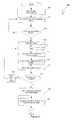
- Some embodiments of the inventionalso include a transceiver 150 connected to the control module 110 for communicating with a dispatcher 160 .
- the transceiver 150can be configured for any type of communication, including communication through rails and wireless communication.
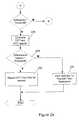
- the speed reported by the EOT and HOT positioning systemsis compared at step 228 .
- the purpose of this comparisonis to ensure that the EOT and HOT are not traveling at significantly different speeds, which would be indicative of a train separation. If the difference in EOT and HOT speeds is greater than a threshold (again, nominally zero but preferably including a safety factor to account for differences in speed caused by slack between cars in train and positioning system errors) at step 230 , then the control module 110 warns the operator of a possible train separation at step 232 .
Landscapes
- Engineering & Computer Science (AREA)
- Mechanical Engineering (AREA)
- Train Traffic Observation, Control, And Security (AREA)
- Electric Propulsion And Braking For Vehicles (AREA)
- Image Processing (AREA)
Abstract
Description
Claims (49)
Priority Applications (5)
| Application Number | Priority Date | Filing Date | Title |
|---|---|---|---|
| US10/440,129US6915191B2 (en) | 2003-05-19 | 2003-05-19 | Method and system for detecting when an end of train has passed a point |
| MXPA05012374AMXPA05012374A (en) | 2003-05-19 | 2004-05-19 | Method and system for detecting when an end of train has passed a point. |
| BRPI0410475-7ABRPI0410475B1 (en) | 2003-05-19 | 2004-05-19 | "Method and System for Determining the Passage of a Train End Through a Point" |
| CA2526224ACA2526224C (en) | 2003-05-19 | 2004-05-19 | Method and system for detecting when an end of train has passed a point |
| PCT/US2004/015737WO2004103791A2 (en) | 2003-05-19 | 2004-05-19 | Method and system for detecting when an end of train has passed a point |
Applications Claiming Priority (1)
| Application Number | Priority Date | Filing Date | Title |
|---|---|---|---|
| US10/440,129US6915191B2 (en) | 2003-05-19 | 2003-05-19 | Method and system for detecting when an end of train has passed a point |
Publications (2)
| Publication Number | Publication Date |
|---|---|
| US20040236482A1 US20040236482A1 (en) | 2004-11-25 |
| US6915191B2true US6915191B2 (en) | 2005-07-05 |
Family
ID=33449767
Family Applications (1)
| Application Number | Title | Priority Date | Filing Date |
|---|---|---|---|
| US10/440,129Expired - LifetimeUS6915191B2 (en) | 2003-05-19 | 2003-05-19 | Method and system for detecting when an end of train has passed a point |
Country Status (5)
| Country | Link |
|---|---|
| US (1) | US6915191B2 (en) |
| BR (1) | BRPI0410475B1 (en) |
| CA (1) | CA2526224C (en) |
| MX (1) | MXPA05012374A (en) |
| WO (1) | WO2004103791A2 (en) |
Cited By (57)
| Publication number | Priority date | Publication date | Assignee | Title |
|---|---|---|---|---|
| US20030026668A1 (en)* | 2001-08-01 | 2003-02-06 | Matthias Blessing | Cutting tool |
| US20050240322A1 (en)* | 2004-04-26 | 2005-10-27 | General Electric Company | Automatic neutral section control system |
| US7024289B2 (en)* | 2002-07-02 | 2006-04-04 | Quantum Engineering, Inc. | Train control system and method of controlling a train or trains |
| US20060184290A1 (en)* | 2003-07-02 | 2006-08-17 | Quantum Engineering Inc. | Method and system for automatically locating end of train devices |
| US20070112482A1 (en)* | 2002-05-31 | 2007-05-17 | Quantum Engineering, Inc. | Method and system for compensating for wheel wear on a train |
| US20070170314A1 (en)* | 2006-01-26 | 2007-07-26 | Kane Mark E | Method and system for locating end of train units |
| US20070233364A1 (en)* | 2006-03-20 | 2007-10-04 | Ajith Kuttannair Kumar | Trip Optimization System and Method for a Vehicle |
| US20080033605A1 (en)* | 2006-03-20 | 2008-02-07 | Wolfgang Daum | System and method for optimizing parameters of multiple rail vehicles operating over multiple intersecting railroad networks |
| US20080082223A1 (en)* | 2006-10-02 | 2008-04-03 | Wolfgang Daum | System and method for optimized fuel efficiency and emission output of a diesel powered system |
| US20080099633A1 (en)* | 2006-10-31 | 2008-05-01 | Quantum Engineering, Inc. | Method and apparatus for sounding horn on a train |
| US20080128562A1 (en)* | 2006-12-01 | 2008-06-05 | Ajith Kuttannair Kumar | Method and apparatus for limiting in-train forces of a railroad train |
| US20080154452A1 (en)* | 2006-03-20 | 2008-06-26 | Kevin Kapp | System and method for predicting a vehicle route using a route network database |
| US20080161984A1 (en)* | 2006-12-01 | 2008-07-03 | Kaitlyn Hrdlicka | System and method for determining a mismatch between a model for a powered system and the actual behavior of the powered system |
| US20080167767A1 (en)* | 2006-03-20 | 2008-07-10 | Brooks James D | Method and Computer Software Code for Determining When to Permit a Speed Control System to Control a Powered System |
| US20080183345A1 (en)* | 2006-03-20 | 2008-07-31 | Ramu Sharat Chandra | Method and Computer Software Code for Determining a Mission Plan for a Powered System When a Desired Mission Parameter Appears Unobtainable |
| US20080183490A1 (en)* | 2006-03-20 | 2008-07-31 | Martin William P | Method and computer software code for implementing a revised mission plan for a powered system |
| US20080201019A1 (en)* | 2006-03-20 | 2008-08-21 | Ajith Kuttannair Kumar | Method and computer software code for optimized fuel efficiency emission output and mission performance of a powered system |
| US20080208401A1 (en)* | 2006-03-20 | 2008-08-28 | Ajith Kuttannair Kumar | System, method, and computer software code for insuring continuous flow of information to an operator of a powered system |
| US20080312775A1 (en)* | 2006-03-20 | 2008-12-18 | Ajith Kuttannair Kumar | System, method, and computer software code for optimizing speed regulation of a remotely controlled powered system |
| US20090043435A1 (en)* | 2007-08-07 | 2009-02-12 | Quantum Engineering, Inc. | Methods and systems for making a gps signal vital |
| US20090109013A1 (en)* | 2007-10-30 | 2009-04-30 | Quantum Engineering, Inc. | Display of non-linked eot units having an emergency status |
| US20090125170A1 (en)* | 2007-04-25 | 2009-05-14 | Joseph Forrest Noffsinger | System and method for optimizing a braking schedule of a powered system traveling along a route |
| US20090182924A1 (en)* | 2006-09-11 | 2009-07-16 | Apple Computer, Inc. | Method and system for controlling power provided to an accessory |
| US20090198391A1 (en)* | 2008-02-05 | 2009-08-06 | Ajith Kuttannair Kumar | System, method and computer software code for obtaining information for routing a powered system and adjusting a route in accordance with relevant information |
| US20090234523A1 (en)* | 2008-03-13 | 2009-09-17 | Vishram Vinayak Nandedkar | System and method for determining a quality of a location estimation of a powered system |
| US20090254239A1 (en)* | 2006-03-20 | 2009-10-08 | Wolfgang Daum | System, method, and computer software code for detecting a physical defect along a mission route |
| US20100023190A1 (en)* | 2006-03-20 | 2010-01-28 | General Electric Company | Trip optimizer method, system and computer software code for operating a railroad train to minimize wheel and track wear |
| US20100168942A1 (en)* | 2008-12-29 | 2010-07-01 | Joseph Forrest Noffsinger | System And Method For Optimizing A Path For A Marine Vessel Through A Waterway |
| US20100213321A1 (en)* | 2009-02-24 | 2010-08-26 | Quantum Engineering, Inc. | Method and systems for end of train force reporting |
| US20100332058A1 (en)* | 2009-06-30 | 2010-12-30 | Quantum Engineering, Inc. | Vital speed profile to control a train moving along a track |
| US20110234451A1 (en)* | 2008-11-28 | 2011-09-29 | Siemens Aktiengesellschaft | Method and device for distance measurement |
| US20120004796A1 (en)* | 2010-04-01 | 2012-01-05 | Alstom Transport Sa | Method for managing the circulation of vehicles on a railway network and related system |
| US8249763B2 (en) | 2006-03-20 | 2012-08-21 | General Electric Company | Method and computer software code for uncoupling power control of a distributed powered system from coupled power settings |
| EP2505452A2 (en) | 2011-04-01 | 2012-10-03 | Invensys Rail Corporation | Communications based crossing control for locomotive-centric systems |
| US8398405B2 (en) | 2006-03-20 | 2013-03-19 | General Electric Company | System, method, and computer software code for instructing an operator to control a powered system having an autonomous controller |
| US8473127B2 (en) | 2006-03-20 | 2013-06-25 | General Electric Company | System, method and computer software code for optimizing train operations considering rail car parameters |
| US8751073B2 (en) | 2006-03-20 | 2014-06-10 | General Electric Company | Method and apparatus for optimizing a train trip using signal information |
| US8768543B2 (en) | 2006-03-20 | 2014-07-01 | General Electric Company | Method, system and computer software code for trip optimization with train/track database augmentation |
| US8788135B2 (en) | 2006-03-20 | 2014-07-22 | General Electric Company | System, method, and computer software code for providing real time optimization of a mission plan for a powered system |
| US20140379181A1 (en)* | 2012-02-03 | 2014-12-25 | Mitsubishi Electric Corporation | Circuit breaker controller for electric train |
| US8924049B2 (en) | 2003-01-06 | 2014-12-30 | General Electric Company | System and method for controlling movement of vehicles |
| US8965604B2 (en) | 2008-03-13 | 2015-02-24 | General Electric Company | System and method for determining a quality value of a location estimation of a powered system |
| US8998617B2 (en) | 2006-03-20 | 2015-04-07 | General Electric Company | System, method, and computer software code for instructing an operator to control a powered system having an autonomous controller |
| US9120493B2 (en) | 2007-04-30 | 2015-09-01 | General Electric Company | Method and apparatus for determining track features and controlling a railroad train responsive thereto |
| US9156477B2 (en) | 2006-03-20 | 2015-10-13 | General Electric Company | Control system and method for remotely isolating powered units in a vehicle system |
| US9201409B2 (en) | 2006-03-20 | 2015-12-01 | General Electric Company | Fuel management system and method |
| US9527518B2 (en) | 2006-03-20 | 2016-12-27 | General Electric Company | System, method and computer software code for controlling a powered system and operational information used in a mission by the powered system |
| US9580090B2 (en) | 2006-12-01 | 2017-02-28 | General Electric Company | System, method, and computer readable medium for improving the handling of a powered system traveling along a route |
| US9669851B2 (en) | 2012-11-21 | 2017-06-06 | General Electric Company | Route examination system and method |
| US9733625B2 (en) | 2006-03-20 | 2017-08-15 | General Electric Company | Trip optimization system and method for a train |
| US9834237B2 (en) | 2012-11-21 | 2017-12-05 | General Electric Company | Route examining system and method |
| US10308265B2 (en) | 2006-03-20 | 2019-06-04 | Ge Global Sourcing Llc | Vehicle control system and method |
| US20190196026A1 (en)* | 2017-12-27 | 2019-06-27 | Westinghouse Air Brake Technologies Corporation | Real-Time Kinematics for End of Train |
| US10569792B2 (en) | 2006-03-20 | 2020-02-25 | General Electric Company | Vehicle control system and method |
| US11002167B2 (en)* | 2016-11-21 | 2021-05-11 | Clean Train Propulsion | Wireless power transfer system |
| US11021180B2 (en) | 2018-04-06 | 2021-06-01 | Siemens Mobility, Inc. | Railway road crossing warning system with sensing system electrically-decoupled from railroad track |
| US20240071214A1 (en)* | 2022-08-25 | 2024-02-29 | Transportation Ip Holdings, Llc | Vehicle monitoring system |
Families Citing this family (15)
| Publication number | Priority date | Publication date | Assignee | Title |
|---|---|---|---|---|
| KR100627603B1 (en)* | 2004-08-30 | 2006-09-25 | 샬롬엔지니어링 주식회사 | A device for automatically detecting separation of a trainformation |
| US7142982B2 (en) | 2004-09-13 | 2006-11-28 | Quantum Engineering, Inc. | System and method for determining relative differential positioning system measurement solutions |
| US7722134B2 (en)* | 2004-10-12 | 2010-05-25 | Invensys Rail Corporation | Failsafe electronic braking system for trains |
| US7222003B2 (en)* | 2005-06-24 | 2007-05-22 | General Electric Company | Method and computer program product for monitoring integrity of railroad train |
| FR2932493B1 (en) | 2008-06-11 | 2010-07-30 | Arkema France | COMPOSITIONS BASED ON HYDROFLUOROOLEFINS |
| CN102201025B (en)* | 2011-07-08 | 2012-09-19 | 中国科学院力学研究所 | A design method for high-speed train head shape |
| US8521345B2 (en) | 2011-12-28 | 2013-08-27 | General Electric Company | System and method for rail vehicle time synchronization |
| US8914168B2 (en)* | 2012-04-05 | 2014-12-16 | Union Pacific Railroad Company | System and method for automated locomotive startup and shutdown recommendations |
| WO2014012164A1 (en)* | 2012-07-17 | 2014-01-23 | Thales Canada Inc. | Intra-train network management system |
| DE102015203476A1 (en) | 2015-02-26 | 2016-09-01 | Siemens Aktiengesellschaft | Method and locating device for determining the position of a track-guided vehicle, in particular of a rail vehicle |
| US20230339526A1 (en)* | 2016-01-21 | 2023-10-26 | Transportation Ip Holdings, Llc | Intersection management system |
| AT519082A1 (en)* | 2016-09-07 | 2018-03-15 | Thales Austria Gmbh | METHOD FOR CREATING A ROUTINE POINT MESSAGE THROUGH A DRIVING TRAIN |
| US11608097B2 (en)* | 2017-02-28 | 2023-03-21 | Thales Canada Inc | Guideway mounted vehicle localization system |
| CH714184A1 (en)* | 2017-09-21 | 2019-03-29 | Marte Gerhard | Method of ensuring that a track block of a railway track is free of the last unit of a train. |
| US20220281496A1 (en)* | 2021-03-08 | 2022-09-08 | Siemens Mobility, Inc. | Automatic end of train device based protection for a railway vehicle |
Citations (53)
| Publication number | Priority date | Publication date | Assignee | Title |
|---|---|---|---|---|
| US4181943A (en) | 1978-05-22 | 1980-01-01 | Hugg Steven B | Speed control device for trains |
| US4459668A (en) | 1980-03-31 | 1984-07-10 | Japanese National Railways | Automatic train control device |
| US4561057A (en) | 1983-04-14 | 1985-12-24 | Halliburton Company | Apparatus and method for monitoring motion of a railroad train |
| US4711418A (en) | 1986-04-08 | 1987-12-08 | General Signal Corporation | Radio based railway signaling and traffic control system |
| US4807127A (en)* | 1986-12-10 | 1989-02-21 | Sumitomo Electric Industries, Ltd. | Vehicle location detecting system |
| US5072900A (en) | 1989-03-17 | 1991-12-17 | Aigle Azur Concept | System for the control of the progression of several railway trains in a network |
| US5129605A (en) | 1990-09-17 | 1992-07-14 | Rockwell International Corporation | Rail vehicle positioning system |
| US5177685A (en) | 1990-08-09 | 1993-01-05 | Massachusetts Institute Of Technology | Automobile navigation system using real time spoken driving instructions |
| US5332180A (en) | 1992-12-28 | 1994-07-26 | Union Switch & Signal Inc. | Traffic control system utilizing on-board vehicle information measurement apparatus |
| US5340062A (en) | 1992-08-13 | 1994-08-23 | Harmon Industries, Inc. | Train control system integrating dynamic and fixed data |
| US5364047A (en) | 1993-04-02 | 1994-11-15 | General Railway Signal Corporation | Automatic vehicle control and location system |
| US5394333A (en) | 1991-12-23 | 1995-02-28 | Zexel Usa Corp. | Correcting GPS position in a hybrid naviation system |
| US5398894A (en) | 1993-08-10 | 1995-03-21 | Union Switch & Signal Inc. | Virtual block control system for railway vehicle |
| US5533695A (en) | 1994-08-19 | 1996-07-09 | Harmon Industries, Inc. | Incremental train control system |
| US5620155A (en) | 1995-03-23 | 1997-04-15 | Michalek; Jan K. | Railway train signalling system for remotely operating warning devices at crossings and for receiving warning device operational information |
| US5699986A (en) | 1996-07-15 | 1997-12-23 | Alternative Safety Technologies | Railway crossing collision avoidance system |
| US5740547A (en) | 1996-02-20 | 1998-04-14 | Westinghouse Air Brake Company | Rail navigation system |
| US5751569A (en) | 1996-03-15 | 1998-05-12 | Safetran Systems Corporation | Geographic train control |
| US5803411A (en) | 1996-10-21 | 1998-09-08 | Abb Daimler-Benz Transportation (North America) Inc. | Method and apparatus for initializing an automated train control system |
| US5817934A (en)* | 1995-07-20 | 1998-10-06 | Westinghouse Air Brake Company | Head of train device |
| US5828979A (en) | 1994-09-01 | 1998-10-27 | Harris Corporation | Automatic train control system and method |
| US5867122A (en) | 1996-10-23 | 1999-02-02 | Harris Corporation | Application of GPS to a railroad navigation system using two satellites and a stored database |
| US5944768A (en) | 1995-10-30 | 1999-08-31 | Aisin Aw Co., Ltd. | Navigation system |
| US5950966A (en) | 1997-09-17 | 1999-09-14 | Westinghouse Airbrake Company | Distributed positive train control system |
| US5969643A (en)* | 1998-02-23 | 1999-10-19 | Westinghouse Air Brake Company | Method and apparatus for determining relative locomotive position in a train consist |
| US5978718A (en) | 1997-07-22 | 1999-11-02 | Westinghouse Air Brake Company | Rail vision system |
| US5995881A (en) | 1997-07-22 | 1999-11-30 | Westinghouse Air Brake Company | Integrated cab signal rail navigation system |
| US6008731A (en)* | 1997-07-30 | 1999-12-28 | Union Switch & Signal, Inc. | Detector for sensing motion and direction of a railway vehicle |
| US6049745A (en) | 1997-02-10 | 2000-04-11 | Fmc Corporation | Navigation system for automatic guided vehicle |
| US6081769A (en)* | 1998-02-23 | 2000-06-27 | Wabtec Corporation | Method and apparatus for determining the overall length of a train |
| US6102340A (en) | 1997-02-07 | 2000-08-15 | Ge-Harris Railway Electronics, Llc | Broken rail detection system and method |
| US6112142A (en) | 1998-06-26 | 2000-08-29 | Quantum Engineering, Inc. | Positive signal comparator and method |
| US6135396A (en) | 1997-02-07 | 2000-10-24 | Ge-Harris Railway Electronics, Llc | System and method for automatic train operation |
| US6179252B1 (en) | 1998-07-17 | 2001-01-30 | The Texas A&M University System | Intelligent rail crossing control system and train tracking system |
| US6218961B1 (en) | 1996-10-23 | 2001-04-17 | G.E. Harris Railway Electronics, L.L.C. | Method and system for proximity detection and location determination |
| US6227625B1 (en)* | 1999-08-24 | 2001-05-08 | Westinghouse Air Brake Company | Two way field tester for EOT device |
| US6311109B1 (en) | 2000-07-24 | 2001-10-30 | New York Air Brake Corporation | Method of determining train and track characteristics using navigational data |
| US6322025B1 (en) | 1999-11-30 | 2001-11-27 | Wabtec Railway Electronics, Inc. | Dual-protocol locomotive control system and method |
| US20010056544A1 (en) | 1998-06-18 | 2001-12-27 | Walker Richard C. | Electrically controlled automated devices to operate, slow, guide, stop and secure, equipment and machinery for the purpose of controlling their unsafe, unattended, unauthorized, unlawful hazardous and/or legal use, with remote control and accountability worldwide |
| US6345233B1 (en) | 1997-08-18 | 2002-02-05 | Dynamic Vehicle Safety Systems, Ltd. | Collision avoidance using GPS device and train proximity detector |
| US6373403B1 (en) | 1997-03-03 | 2002-04-16 | Kelvin Korver | Apparatus and method for improving the safety of railroad systems |
| US6374184B1 (en) | 1999-09-10 | 2002-04-16 | Ge-Harris Railway Electronics, Llc | Methods and apparatus for determining that a train has changed paths |
| US6371416B1 (en) | 2000-08-01 | 2002-04-16 | New York Air Brake Corporation | Portable beacons |
| US6377877B1 (en) | 2000-09-15 | 2002-04-23 | Ge Harris Railway Electronics, Llc | Method of determining railyard status using locomotive location |
| US6397147B1 (en) | 2000-06-06 | 2002-05-28 | Csi Wireless Inc. | Relative GPS positioning using a single GPS receiver with internally generated differential correction terms |
| US20020070879A1 (en) | 2000-12-12 | 2002-06-13 | Gazit Hanoch Amatzia | "On-board" vehicle safety system |
| US6421587B2 (en) | 1999-12-30 | 2002-07-16 | Ge Harris Railway Electronics, Llc | Methods and apparatus for locomotive consist determination |
| US6456937B1 (en) | 1999-12-30 | 2002-09-24 | General Electric Company | Methods and apparatus for locomotive tracking |
| US6459965B1 (en) | 2000-11-22 | 2002-10-01 | Ge-Harris Railway Electronics, Llc | Method for advanced communication-based vehicle control |
| US6459964B1 (en) | 1994-09-01 | 2002-10-01 | G.E. Harris Railway Electronics, L.L.C. | Train schedule repairer |
| US6487478B1 (en) | 1999-10-28 | 2002-11-26 | General Electric Company | On-board monitor for railroad locomotive |
| US6609049B1 (en) | 2002-07-01 | 2003-08-19 | Quantum Engineering, Inc. | Method and system for automatically activating a warning device on a train |
| US20030225490A1 (en) | 2002-05-31 | 2003-12-04 | Kane Mark Edward | Method and system for compensating for wheel wear on a train |
- 2003
- 2003-05-19USUS10/440,129patent/US6915191B2/ennot_activeExpired - Lifetime
- 2004
- 2004-05-19WOPCT/US2004/015737patent/WO2004103791A2/enactiveApplication Filing
- 2004-05-19BRBRPI0410475-7Apatent/BRPI0410475B1/enactiveIP Right Grant
- 2004-05-19MXMXPA05012374Apatent/MXPA05012374A/enactiveIP Right Grant
- 2004-05-19CACA2526224Apatent/CA2526224C/ennot_activeExpired - Lifetime
Patent Citations (57)
| Publication number | Priority date | Publication date | Assignee | Title |
|---|---|---|---|---|
| US4181943A (en) | 1978-05-22 | 1980-01-01 | Hugg Steven B | Speed control device for trains |
| US4459668A (en) | 1980-03-31 | 1984-07-10 | Japanese National Railways | Automatic train control device |
| US4561057A (en) | 1983-04-14 | 1985-12-24 | Halliburton Company | Apparatus and method for monitoring motion of a railroad train |
| US4711418A (en) | 1986-04-08 | 1987-12-08 | General Signal Corporation | Radio based railway signaling and traffic control system |
| US4807127A (en)* | 1986-12-10 | 1989-02-21 | Sumitomo Electric Industries, Ltd. | Vehicle location detecting system |
| US5072900A (en) | 1989-03-17 | 1991-12-17 | Aigle Azur Concept | System for the control of the progression of several railway trains in a network |
| US5177685A (en) | 1990-08-09 | 1993-01-05 | Massachusetts Institute Of Technology | Automobile navigation system using real time spoken driving instructions |
| US5129605A (en) | 1990-09-17 | 1992-07-14 | Rockwell International Corporation | Rail vehicle positioning system |
| US5394333A (en) | 1991-12-23 | 1995-02-28 | Zexel Usa Corp. | Correcting GPS position in a hybrid naviation system |
| US5452870A (en) | 1992-08-13 | 1995-09-26 | Harmon Industries, Inc. | Fixed data transmission system for controlling train movement |
| US5340062A (en) | 1992-08-13 | 1994-08-23 | Harmon Industries, Inc. | Train control system integrating dynamic and fixed data |
| US5332180A (en) | 1992-12-28 | 1994-07-26 | Union Switch & Signal Inc. | Traffic control system utilizing on-board vehicle information measurement apparatus |
| US5364047A (en) | 1993-04-02 | 1994-11-15 | General Railway Signal Corporation | Automatic vehicle control and location system |
| US5398894A (en) | 1993-08-10 | 1995-03-21 | Union Switch & Signal Inc. | Virtual block control system for railway vehicle |
| US5398894B1 (en) | 1993-08-10 | 1998-09-29 | Union Switch & Signal Inc | Virtual block control system for railway vehicle |
| US5533695A (en) | 1994-08-19 | 1996-07-09 | Harmon Industries, Inc. | Incremental train control system |
| US6459964B1 (en) | 1994-09-01 | 2002-10-01 | G.E. Harris Railway Electronics, L.L.C. | Train schedule repairer |
| US5828979A (en) | 1994-09-01 | 1998-10-27 | Harris Corporation | Automatic train control system and method |
| US5620155A (en) | 1995-03-23 | 1997-04-15 | Michalek; Jan K. | Railway train signalling system for remotely operating warning devices at crossings and for receiving warning device operational information |
| US5817934A (en)* | 1995-07-20 | 1998-10-06 | Westinghouse Air Brake Company | Head of train device |
| US5944768A (en) | 1995-10-30 | 1999-08-31 | Aisin Aw Co., Ltd. | Navigation system |
| US5740547A (en) | 1996-02-20 | 1998-04-14 | Westinghouse Air Brake Company | Rail navigation system |
| US5751569A (en) | 1996-03-15 | 1998-05-12 | Safetran Systems Corporation | Geographic train control |
| US5699986A (en) | 1996-07-15 | 1997-12-23 | Alternative Safety Technologies | Railway crossing collision avoidance system |
| US5890682A (en)* | 1996-07-15 | 1999-04-06 | Alternative Safety Technologies | Railway crossing collision avoidance system |
| US5803411A (en) | 1996-10-21 | 1998-09-08 | Abb Daimler-Benz Transportation (North America) Inc. | Method and apparatus for initializing an automated train control system |
| US5867122A (en) | 1996-10-23 | 1999-02-02 | Harris Corporation | Application of GPS to a railroad navigation system using two satellites and a stored database |
| US6218961B1 (en) | 1996-10-23 | 2001-04-17 | G.E. Harris Railway Electronics, L.L.C. | Method and system for proximity detection and location determination |
| US6102340A (en) | 1997-02-07 | 2000-08-15 | Ge-Harris Railway Electronics, Llc | Broken rail detection system and method |
| US6135396A (en) | 1997-02-07 | 2000-10-24 | Ge-Harris Railway Electronics, Llc | System and method for automatic train operation |
| US6049745A (en) | 1997-02-10 | 2000-04-11 | Fmc Corporation | Navigation system for automatic guided vehicle |
| US6373403B1 (en) | 1997-03-03 | 2002-04-16 | Kelvin Korver | Apparatus and method for improving the safety of railroad systems |
| US5995881A (en) | 1997-07-22 | 1999-11-30 | Westinghouse Air Brake Company | Integrated cab signal rail navigation system |
| US5978718A (en) | 1997-07-22 | 1999-11-02 | Westinghouse Air Brake Company | Rail vision system |
| US6008731A (en)* | 1997-07-30 | 1999-12-28 | Union Switch & Signal, Inc. | Detector for sensing motion and direction of a railway vehicle |
| US6345233B1 (en) | 1997-08-18 | 2002-02-05 | Dynamic Vehicle Safety Systems, Ltd. | Collision avoidance using GPS device and train proximity detector |
| US5950966A (en) | 1997-09-17 | 1999-09-14 | Westinghouse Airbrake Company | Distributed positive train control system |
| US6081769A (en)* | 1998-02-23 | 2000-06-27 | Wabtec Corporation | Method and apparatus for determining the overall length of a train |
| US5969643A (en)* | 1998-02-23 | 1999-10-19 | Westinghouse Air Brake Company | Method and apparatus for determining relative locomotive position in a train consist |
| US20010056544A1 (en) | 1998-06-18 | 2001-12-27 | Walker Richard C. | Electrically controlled automated devices to operate, slow, guide, stop and secure, equipment and machinery for the purpose of controlling their unsafe, unattended, unauthorized, unlawful hazardous and/or legal use, with remote control and accountability worldwide |
| US6112142A (en) | 1998-06-26 | 2000-08-29 | Quantum Engineering, Inc. | Positive signal comparator and method |
| US6179252B1 (en) | 1998-07-17 | 2001-01-30 | The Texas A&M University System | Intelligent rail crossing control system and train tracking system |
| US6227625B1 (en)* | 1999-08-24 | 2001-05-08 | Westinghouse Air Brake Company | Two way field tester for EOT device |
| US6374184B1 (en) | 1999-09-10 | 2002-04-16 | Ge-Harris Railway Electronics, Llc | Methods and apparatus for determining that a train has changed paths |
| US6487478B1 (en) | 1999-10-28 | 2002-11-26 | General Electric Company | On-board monitor for railroad locomotive |
| US6322025B1 (en) | 1999-11-30 | 2001-11-27 | Wabtec Railway Electronics, Inc. | Dual-protocol locomotive control system and method |
| US6421587B2 (en) | 1999-12-30 | 2002-07-16 | Ge Harris Railway Electronics, Llc | Methods and apparatus for locomotive consist determination |
| US6456937B1 (en) | 1999-12-30 | 2002-09-24 | General Electric Company | Methods and apparatus for locomotive tracking |
| US6397147B1 (en) | 2000-06-06 | 2002-05-28 | Csi Wireless Inc. | Relative GPS positioning using a single GPS receiver with internally generated differential correction terms |
| US6311109B1 (en) | 2000-07-24 | 2001-10-30 | New York Air Brake Corporation | Method of determining train and track characteristics using navigational data |
| US6480766B2 (en)* | 2000-07-24 | 2002-11-12 | New York Air Brake Corporation | Method of determining train and track characteristics using navigational data |
| US6371416B1 (en) | 2000-08-01 | 2002-04-16 | New York Air Brake Corporation | Portable beacons |
| US6377877B1 (en) | 2000-09-15 | 2002-04-23 | Ge Harris Railway Electronics, Llc | Method of determining railyard status using locomotive location |
| US6459965B1 (en) | 2000-11-22 | 2002-10-01 | Ge-Harris Railway Electronics, Llc | Method for advanced communication-based vehicle control |
| US20020070879A1 (en) | 2000-12-12 | 2002-06-13 | Gazit Hanoch Amatzia | "On-board" vehicle safety system |
| US20030225490A1 (en) | 2002-05-31 | 2003-12-04 | Kane Mark Edward | Method and system for compensating for wheel wear on a train |
| US6609049B1 (en) | 2002-07-01 | 2003-08-19 | Quantum Engineering, Inc. | Method and system for automatically activating a warning device on a train |
Non-Patent Citations (49)
| Title |
|---|
| "A New World for Communications & Signaling", Progressive Railroading, May 1986. |
| "Advanced Train Control Gain Momentum", Progressive Railroading, Mar. 1986. |
| "ATCS Evolving on Railroads", Progressive Railroading, Dec. 1992. |
| "ATCS Moving-slowly but Steadily from Lab for Field", Progressive Railroading, Dec. 1994. |
| "ATCS on Verge of Implementation", Progressive Railroading, Dec. 1989. |
| "ATCS's System Engineer", Progressive Railroading, Jul. 1988. |
| "C<SUP>3 </SUP>Comes to the Railroads", Progressive Railroading, Sep. 1989. |
| "Communications/Signaling: Vital for dramatic railroad advances", Progressive Railroading, May 1988. |
| "CP Advances in Train Control", Progressive Railroading, Sep. 1987. |
| "Electronic Advances Improve How Railroads Manage", Progressive Railroading, Dec. 1995. |
| "FRA Promotes Technology to Avoid Train-To-Train Collisions", Progressive Railroading, Aug. 1994. |
| "High Tech Advances Keep Railroads Rolling", Progressive Railroading, May 1994. |
| "On the Threshold of ATCS", Progressive Railroading, Dec. 1987. |
| "PTS Would've Prevented Silver Spring Crash: NTSB", Progressive Railroading, Jul. 1997. |
| "Railroads Take High Tech in Stride", Progressive Railroading, May 1985. |
| "System Architecture, ATCS Specification 100", May 1995. |
| "Testimony of Jolene M. Molitoris, Federal Railroad Administrator, U.S. Department of Transportation before the House Committee on Transportation and Infrastructure Subcommittee on Railroads", Federal Railroad Administration, United States Department of Transportation, Apr. 1, 1998. |
| "The Electronic Railroad Emerges", Progressive Railroading, May 1989. |
| Buchanan, Alex, "Service Information Where has the Caboose Gone . . .", Virginia Railway Express, Commuter Weekly, Mar. 5, 2002. |
| Burke, J., "How R&D is Shaping the 21st Century Railroad", Railway Age, Aug. 1998. |
| Department of Transportation Federal Railroad Administration, Federal Register, vol. 66, No. 155, pp. 42352-42396, Aug. 10, 2001. |
| Derocher, Robert J., "Transit Projects Setting Pace for Train Control", Progressive Railroading, Jun. 1998. |
| Foran, P., "A Controlling Interest In Interoperability", Progressive Railroading, Apr. 1998. |
| Foran, P., "A 'Positive' Answer to the Interoperability Call", Progressive Railroading, Sep. 1997. |
| Foran, P., "How Safe is Safe Enough?", Progressive Railroading, Oct. 1997. |
| Foran, P., "Train Control Quandary, Is CBTC viable? Railroads, Suppliers Hope Pilot Projects Provide Clues", Progressive Railroading, Jun. 1997. |
| Furman, E., et al., "Keeping Track of RF", GPS World, Feb. 2001. |
| Gallamore, R., "The Curtain Rises on the Next Generation", Railway Age, Jul. 1998. |
| GE Harris Product Sheet: "Advanced Systems for Optimizing Rail Performance" and "Advanced Products for Optimizing train Performance", undated. |
| GE Harris Product Sheet: "Advanced, Satellite-Based Warning System Enhances Operating Safety", undated. |
| Judge, T., "BNSF/UP PTS Pilot Advances in Northwest", Progressive Railroading, May 1996. |
| Judge, T., "Electronic Advances Keeping Railroads Rolling", Progressive Railroading, Jun. 1995. |
| Kube, K., "Innovation in Inches", Progressive Railroading, Feb. 2002. |
| Kube, K., "Variations on a Theme", Progressive Railroading, Dec. 2001. |
| Lindsey, Ron A., "C B T M, Communications Based Train Management", Railway Fuel and Operating Officers Association, Annual Proceedings, 1999, (month is not available). |
| Lundsten, Carsten S., "Railroad Rules, Signalling, Operations: Track Warrant Control", Nov. 7, 1998. |
| Lyle, Denise, "Positive Train Control on CSXT", Railway Fuel and Operating Officers Association, Annual Proceedings, 2000, (month is not available). |
| Malone, Frank, "The Gaps Start to Close"Progressive Railroading, May 1987. |
| Moody, Howard G, "Advanced Train Control Systems A System to Manage Railroad Operations", Railway Fuel and Operating Officers Association, Annual Proceedings, 1993, (month is not available). |
| Moore, W., "How CBTC Can Increase Capacity", Railway Age, Apr., 2001. |
| Ruegg, G.A., "Advanced Train Control Systems ATCS", Railway Fuel and Operating Officers Association, Annual Proceedings, 1986, (month is not available). |
| Sullivan, T., "PTC: A Maturing Technology", Railway Age, Apr. 2000. |
| Sullivan, T., "PTC-Is FRA Pushing Too Hard?", Railway Age, Aug. 1999. |
| Union Switch & Signal Intermittent Cab Signal, Bulletin 53, 1998, (month is not available). |
| Vantuono, W., "CBTC: A Maturing Technology", Third International Conference On Communications Based Train Control, Railway Age, Jun. 1999. |
| Vantuono, W., "CBTC: The Jury is Still Out", Railway Age, Jun. 2001. |
| Vantuono, W., "Do you know where your train is?", Railway Age, Feb. 1996. |
| Vantuono, W., "New York Leads a Revolution", Railway Age, Sep. 1996. |
| Vantuono, W., "New-tech Train Control Takes Off", Railway Age, May 2002. |
Cited By (88)
| Publication number | Priority date | Publication date | Assignee | Title |
|---|---|---|---|---|
| US20030026668A1 (en)* | 2001-08-01 | 2003-02-06 | Matthias Blessing | Cutting tool |
| US20070112482A1 (en)* | 2002-05-31 | 2007-05-17 | Quantum Engineering, Inc. | Method and system for compensating for wheel wear on a train |
| US7593795B2 (en) | 2002-05-31 | 2009-09-22 | Quantum Engineering, Inc. | Method and system for compensating for wheel wear on a train |
| US7024289B2 (en)* | 2002-07-02 | 2006-04-04 | Quantum Engineering, Inc. | Train control system and method of controlling a train or trains |
| US8924049B2 (en) | 2003-01-06 | 2014-12-30 | General Electric Company | System and method for controlling movement of vehicles |
| US7467032B2 (en)* | 2003-07-02 | 2008-12-16 | Quantum Engineering, Inc. | Method and system for automatically locating end of train devices |
| US20060184290A1 (en)* | 2003-07-02 | 2006-08-17 | Quantum Engineering Inc. | Method and system for automatically locating end of train devices |
| US20100253548A1 (en)* | 2003-07-02 | 2010-10-07 | Invensys Rail Corporation | Method and system for automatically locating end of train devices |
| US7742850B2 (en) | 2003-07-02 | 2010-06-22 | Invensys Rail Corporation | Method and system for automatically locating end of train devices |
| US20050240322A1 (en)* | 2004-04-26 | 2005-10-27 | General Electric Company | Automatic neutral section control system |
| US7162337B2 (en)* | 2004-04-26 | 2007-01-09 | General Electric Company | Automatic neutral section control system |
| US20070170314A1 (en)* | 2006-01-26 | 2007-07-26 | Kane Mark E | Method and system for locating end of train units |
| US9233696B2 (en) | 2006-03-20 | 2016-01-12 | General Electric Company | Trip optimizer method, system and computer software code for operating a railroad train to minimize wheel and track wear |
| US9156477B2 (en) | 2006-03-20 | 2015-10-13 | General Electric Company | Control system and method for remotely isolating powered units in a vehicle system |
| US20080167767A1 (en)* | 2006-03-20 | 2008-07-10 | Brooks James D | Method and Computer Software Code for Determining When to Permit a Speed Control System to Control a Powered System |
| US20080183345A1 (en)* | 2006-03-20 | 2008-07-31 | Ramu Sharat Chandra | Method and Computer Software Code for Determining a Mission Plan for a Powered System When a Desired Mission Parameter Appears Unobtainable |
| US20080183490A1 (en)* | 2006-03-20 | 2008-07-31 | Martin William P | Method and computer software code for implementing a revised mission plan for a powered system |
| US20080201019A1 (en)* | 2006-03-20 | 2008-08-21 | Ajith Kuttannair Kumar | Method and computer software code for optimized fuel efficiency emission output and mission performance of a powered system |
| US20080208401A1 (en)* | 2006-03-20 | 2008-08-28 | Ajith Kuttannair Kumar | System, method, and computer software code for insuring continuous flow of information to an operator of a powered system |
| US20080154452A1 (en)* | 2006-03-20 | 2008-06-26 | Kevin Kapp | System and method for predicting a vehicle route using a route network database |
| US20080312775A1 (en)* | 2006-03-20 | 2008-12-18 | Ajith Kuttannair Kumar | System, method, and computer software code for optimizing speed regulation of a remotely controlled powered system |
| US9733625B2 (en) | 2006-03-20 | 2017-08-15 | General Electric Company | Trip optimization system and method for a train |
| US9527518B2 (en) | 2006-03-20 | 2016-12-27 | General Electric Company | System, method and computer software code for controlling a powered system and operational information used in a mission by the powered system |
| US9266542B2 (en) | 2006-03-20 | 2016-02-23 | General Electric Company | System and method for optimized fuel efficiency and emission output of a diesel powered system |
| US8401720B2 (en) | 2006-03-20 | 2013-03-19 | General Electric Company | System, method, and computer software code for detecting a physical defect along a mission route |
| US8398405B2 (en) | 2006-03-20 | 2013-03-19 | General Electric Company | System, method, and computer software code for instructing an operator to control a powered system having an autonomous controller |
| US9201409B2 (en) | 2006-03-20 | 2015-12-01 | General Electric Company | Fuel management system and method |
| US10569792B2 (en) | 2006-03-20 | 2020-02-25 | General Electric Company | Vehicle control system and method |
| US20090254239A1 (en)* | 2006-03-20 | 2009-10-08 | Wolfgang Daum | System, method, and computer software code for detecting a physical defect along a mission route |
| US20100023190A1 (en)* | 2006-03-20 | 2010-01-28 | General Electric Company | Trip optimizer method, system and computer software code for operating a railroad train to minimize wheel and track wear |
| US8370007B2 (en) | 2006-03-20 | 2013-02-05 | General Electric Company | Method and computer software code for determining when to permit a speed control system to control a powered system |
| US10308265B2 (en) | 2006-03-20 | 2019-06-04 | Ge Global Sourcing Llc | Vehicle control system and method |
| US8295993B2 (en) | 2006-03-20 | 2012-10-23 | General Electric Company | System, method, and computer software code for optimizing speed regulation of a remotely controlled powered system |
| US20080033605A1 (en)* | 2006-03-20 | 2008-02-07 | Wolfgang Daum | System and method for optimizing parameters of multiple rail vehicles operating over multiple intersecting railroad networks |
| US8998617B2 (en) | 2006-03-20 | 2015-04-07 | General Electric Company | System, method, and computer software code for instructing an operator to control a powered system having an autonomous controller |
| US20070233364A1 (en)* | 2006-03-20 | 2007-10-04 | Ajith Kuttannair Kumar | Trip Optimization System and Method for a Vehicle |
| US7974774B2 (en) | 2006-03-20 | 2011-07-05 | General Electric Company | Trip optimization system and method for a vehicle |
| US8903573B2 (en) | 2006-03-20 | 2014-12-02 | General Electric Company | Method and computer software code for determining a mission plan for a powered system when a desired mission parameter appears unobtainable |
| US8788135B2 (en) | 2006-03-20 | 2014-07-22 | General Electric Company | System, method, and computer software code for providing real time optimization of a mission plan for a powered system |
| US8126601B2 (en) | 2006-03-20 | 2012-02-28 | General Electric Company | System and method for predicting a vehicle route using a route network database |
| US8768543B2 (en) | 2006-03-20 | 2014-07-01 | General Electric Company | Method, system and computer software code for trip optimization with train/track database augmentation |
| US8751073B2 (en) | 2006-03-20 | 2014-06-10 | General Electric Company | Method and apparatus for optimizing a train trip using signal information |
| US8725326B2 (en) | 2006-03-20 | 2014-05-13 | General Electric Company | System and method for predicting a vehicle route using a route network database |
| US8630757B2 (en) | 2006-03-20 | 2014-01-14 | General Electric Company | System and method for optimizing parameters of multiple rail vehicles operating over multiple intersecting railroad networks |
| US8249763B2 (en) | 2006-03-20 | 2012-08-21 | General Electric Company | Method and computer software code for uncoupling power control of a distributed powered system from coupled power settings |
| US8473127B2 (en) | 2006-03-20 | 2013-06-25 | General Electric Company | System, method and computer software code for optimizing train operations considering rail car parameters |
| US8290645B2 (en) | 2006-03-20 | 2012-10-16 | General Electric Company | Method and computer software code for determining a mission plan for a powered system when a desired mission parameter appears unobtainable |
| US20090182924A1 (en)* | 2006-09-11 | 2009-07-16 | Apple Computer, Inc. | Method and system for controlling power provided to an accessory |
| US20080082223A1 (en)* | 2006-10-02 | 2008-04-03 | Wolfgang Daum | System and method for optimized fuel efficiency and emission output of a diesel powered system |
| US20080099633A1 (en)* | 2006-10-31 | 2008-05-01 | Quantum Engineering, Inc. | Method and apparatus for sounding horn on a train |
| US9037323B2 (en) | 2006-12-01 | 2015-05-19 | General Electric Company | Method and apparatus for limiting in-train forces of a railroad train |
| US20080128562A1 (en)* | 2006-12-01 | 2008-06-05 | Ajith Kuttannair Kumar | Method and apparatus for limiting in-train forces of a railroad train |
| US8229607B2 (en) | 2006-12-01 | 2012-07-24 | General Electric Company | System and method for determining a mismatch between a model for a powered system and the actual behavior of the powered system |
| US20080161984A1 (en)* | 2006-12-01 | 2008-07-03 | Kaitlyn Hrdlicka | System and method for determining a mismatch between a model for a powered system and the actual behavior of the powered system |
| US9193364B2 (en) | 2006-12-01 | 2015-11-24 | General Electric Company | Method and apparatus for limiting in-train forces of a railroad train |
| US9580090B2 (en) | 2006-12-01 | 2017-02-28 | General Electric Company | System, method, and computer readable medium for improving the handling of a powered system traveling along a route |
| US20090125170A1 (en)* | 2007-04-25 | 2009-05-14 | Joseph Forrest Noffsinger | System and method for optimizing a braking schedule of a powered system traveling along a route |
| US8180544B2 (en) | 2007-04-25 | 2012-05-15 | General Electric Company | System and method for optimizing a braking schedule of a powered system traveling along a route |
| US9120493B2 (en) | 2007-04-30 | 2015-09-01 | General Electric Company | Method and apparatus for determining track features and controlling a railroad train responsive thereto |
| US20090043435A1 (en)* | 2007-08-07 | 2009-02-12 | Quantum Engineering, Inc. | Methods and systems for making a gps signal vital |
| US20090109013A1 (en)* | 2007-10-30 | 2009-04-30 | Quantum Engineering, Inc. | Display of non-linked eot units having an emergency status |
| US7872591B2 (en) | 2007-10-30 | 2011-01-18 | Invensys Rail Corporation | Display of non-linked EOT units having an emergency status |
| US8798902B2 (en) | 2008-02-05 | 2014-08-05 | General Electric Company | System, method and computer software code for obtaining information for routing a powered system and adjusting a route in accordance with relevant information |
| US20090198391A1 (en)* | 2008-02-05 | 2009-08-06 | Ajith Kuttannair Kumar | System, method and computer software code for obtaining information for routing a powered system and adjusting a route in accordance with relevant information |
| US20090234523A1 (en)* | 2008-03-13 | 2009-09-17 | Vishram Vinayak Nandedkar | System and method for determining a quality of a location estimation of a powered system |
| US8965604B2 (en) | 2008-03-13 | 2015-02-24 | General Electric Company | System and method for determining a quality value of a location estimation of a powered system |
| US8190312B2 (en) | 2008-03-13 | 2012-05-29 | General Electric Company | System and method for determining a quality of a location estimation of a powered system |
| US20110234451A1 (en)* | 2008-11-28 | 2011-09-29 | Siemens Aktiengesellschaft | Method and device for distance measurement |
| US20100168942A1 (en)* | 2008-12-29 | 2010-07-01 | Joseph Forrest Noffsinger | System And Method For Optimizing A Path For A Marine Vessel Through A Waterway |
| US8155811B2 (en) | 2008-12-29 | 2012-04-10 | General Electric Company | System and method for optimizing a path for a marine vessel through a waterway |
| US20100213321A1 (en)* | 2009-02-24 | 2010-08-26 | Quantum Engineering, Inc. | Method and systems for end of train force reporting |
| US9168935B2 (en) | 2009-06-30 | 2015-10-27 | Siemens Industry, Inc. | Vital speed profile to control a train moving along a track |
| US8509970B2 (en) | 2009-06-30 | 2013-08-13 | Invensys Rail Corporation | Vital speed profile to control a train moving along a track |
| US20100332058A1 (en)* | 2009-06-30 | 2010-12-30 | Quantum Engineering, Inc. | Vital speed profile to control a train moving along a track |
| US8820685B2 (en)* | 2010-04-01 | 2014-09-02 | Alstom Transport Sa | Method for managing the circulation of vehicles on a railway network and related system |
| US20120004796A1 (en)* | 2010-04-01 | 2012-01-05 | Alstom Transport Sa | Method for managing the circulation of vehicles on a railway network and related system |
| US8668169B2 (en) | 2011-04-01 | 2014-03-11 | Siemens Rail Automation Corporation | Communications based crossing control for locomotive-centric systems |
| EP2505452A2 (en) | 2011-04-01 | 2012-10-03 | Invensys Rail Corporation | Communications based crossing control for locomotive-centric systems |
| EP3521134A1 (en) | 2011-04-01 | 2019-08-07 | Siemens Industry, Inc. | Communications based crossing control for locomotive-centric systems |
| US20140379181A1 (en)* | 2012-02-03 | 2014-12-25 | Mitsubishi Electric Corporation | Circuit breaker controller for electric train |
| US9260014B2 (en)* | 2012-02-03 | 2016-02-16 | Mitsubishi Electric Corporation | Circuit breaker controller for electric train |
| US9669851B2 (en) | 2012-11-21 | 2017-06-06 | General Electric Company | Route examination system and method |
| US9834237B2 (en) | 2012-11-21 | 2017-12-05 | General Electric Company | Route examining system and method |
| US11002167B2 (en)* | 2016-11-21 | 2021-05-11 | Clean Train Propulsion | Wireless power transfer system |
| US20190196026A1 (en)* | 2017-12-27 | 2019-06-27 | Westinghouse Air Brake Technologies Corporation | Real-Time Kinematics for End of Train |
| US10859714B2 (en)* | 2017-12-27 | 2020-12-08 | Westinghouse Air Brake Technologies Corporation | Real-time kinematics for end of train |
| US11021180B2 (en) | 2018-04-06 | 2021-06-01 | Siemens Mobility, Inc. | Railway road crossing warning system with sensing system electrically-decoupled from railroad track |
| US20240071214A1 (en)* | 2022-08-25 | 2024-02-29 | Transportation Ip Holdings, Llc | Vehicle monitoring system |
Also Published As
| Publication number | Publication date |
|---|---|
| BRPI0410475B1 (en) | 2018-06-26 |
| US20040236482A1 (en) | 2004-11-25 |
| MXPA05012374A (en) | 2006-05-25 |
| CA2526224A1 (en) | 2004-12-02 |
| CA2526224C (en) | 2010-09-28 |
| BRPI0410475A (en) | 2006-05-30 |
| WO2004103791A3 (en) | 2005-02-24 |
| WO2004103791A2 (en) | 2004-12-02 |
Similar Documents
| Publication | Publication Date | Title |
|---|---|---|
| US6915191B2 (en) | Method and system for detecting when an end of train has passed a point | |
| US7024289B2 (en) | Train control system and method of controlling a train or trains | |
| AU2012238325B2 (en) | A method and system for identifying train location in a multiple track area | |
| US8296065B2 (en) | System and method for vitally determining position and position uncertainty of a railroad vehicle employing diverse sensors including a global positioning system sensor | |
| CN107709136B (en) | Method and device for determining driving authorization for a rail vehicle | |
| RU2355596C1 (en) | Method for traction equipment control and traffic safety ensuring and integrated complex system (ics) for its implementation | |
| CN112477929A (en) | Train operation control method and device and electronic equipment | |
| CN110730741B (en) | Method for operating a rail-bound transport system, vehicle arrangement and control device | |
| RU2288856C2 (en) | System to prevent collision of train or locomotive with arriving or departing train | |
| JP7496810B2 (en) | On-board equipment | |
| Archibald et al. | An Innovative Low Cost Location Determination System for Railroad Positive Train Control Applications | |
| HK40015389B (en) | Method, vehicle device, and controller for operating a track-bound traffic system | |
| HK40015389A (en) | Method, vehicle device, and controller for operating a track-bound traffic system | |
| HK1212305A1 (en) | Method for computing an interval of positions for a railway vehicle along a railway track and corresponding device |
Legal Events
| Date | Code | Title | Description |
|---|---|---|---|
| AS | Assignment | Owner name:QUANTUM ENGINEERING, INC., FLORIDA Free format text:ASSIGNMENT OF ASSIGNORS INTEREST;ASSIGNORS:KANE, MARK EDWARD;SHOCKLEY, JAMES FRANCIS;HICKENLOOPER, HARRISON THOMAS;REEL/FRAME:014095/0077 Effective date:20030430 | |
| STCF | Information on status: patent grant | Free format text:PATENTED CASE | |
| FEPP | Fee payment procedure | Free format text:PAT HOLDER NO LONGER CLAIMS SMALL ENTITY STATUS, ENTITY STATUS SET TO UNDISCOUNTED (ORIGINAL EVENT CODE: STOL); ENTITY STATUS OF PATENT OWNER: LARGE ENTITY | |
| FPAY | Fee payment | Year of fee payment:4 | |
| AS | Assignment | Owner name:INVENSYS RAIL CORPORATION,KENTUCKY Free format text:ASSIGNMENT OF ASSIGNORS INTEREST;ASSIGNOR:QUANTUM ENGINEERING, INC.;REEL/FRAME:024128/0423 Effective date:20100101 Owner name:INVENSYS RAIL CORPORATION, KENTUCKY Free format text:ASSIGNMENT OF ASSIGNORS INTEREST;ASSIGNOR:QUANTUM ENGINEERING, INC.;REEL/FRAME:024128/0423 Effective date:20100101 | |
| FPAY | Fee payment | Year of fee payment:8 | |
| AS | Assignment | Owner name:SIEMENS RAIL AUTOMATION CORPORATION, KENTUCKY Free format text:CHANGE OF NAME;ASSIGNOR:INVENSYS RAIL CORPORATION;REEL/FRAME:031217/0423 Effective date:20130701 | |
| AS | Assignment | Owner name:SIEMENS INDUSTRY, INC., GEORGIA Free format text:MERGER;ASSIGNORS:SIEMENS RAIL AUTOMATION CORPORATION;SIEMENS INDUSTRY, INC.;REEL/FRAME:032689/0075 Effective date:20140331 | |
| FPAY | Fee payment | Year of fee payment:12 | |
| AS | Assignment | Owner name:SIEMENS MOBILITY, INC., NEW YORK Free format text:ASSIGNMENT OF ASSIGNORS INTEREST;ASSIGNOR:SIEMENS INDUSTRY, INC;REEL/FRAME:049841/0758 Effective date:20190227 |