US6914201B2 - Multiple detent switch - Google Patents
Multiple detent switchDownload PDFInfo
- Publication number
- US6914201B2 US6914201B2US10/721,187US72118703AUS6914201B2US 6914201 B2US6914201 B2US 6914201B2US 72118703 AUS72118703 AUS 72118703AUS 6914201 B2US6914201 B2US 6914201B2
- Authority
- US
- United States
- Prior art keywords
- lever
- switch
- button
- base
- tactile
- Prior art date
- Legal status (The legal status is an assumption and is not a legal conclusion. Google has not performed a legal analysis and makes no representation as to the accuracy of the status listed.)
- Expired - Lifetime, expires
Links
- 230000006870functionEffects0.000claimsdescription42
- 238000000034methodMethods0.000claimsdescription11
- 230000004044responseEffects0.000claimsdescription8
- 239000002184metalSubstances0.000claimsdescription6
- 230000004913activationEffects0.000claimsdescription3
- 230000008901benefitEffects0.000description7
- 230000009977dual effectEffects0.000description6
- 239000000463materialSubstances0.000description4
- 230000035807sensationEffects0.000description4
- 238000004891communicationMethods0.000description2
- 239000004020conductorSubstances0.000description2
- 238000012986modificationMethods0.000description2
- 230000004048modificationEffects0.000description2
- 230000015572biosynthetic processEffects0.000description1
- 239000003086colorantSubstances0.000description1
- 238000010586diagramMethods0.000description1
- 230000003467diminishing effectEffects0.000description1
- 238000005755formation reactionMethods0.000description1
- 238000005286illuminationMethods0.000description1
- 238000010102injection blow mouldingMethods0.000description1
- 238000001746injection mouldingMethods0.000description1
- 239000002991molded plasticSubstances0.000description1
- 239000004033plasticSubstances0.000description1
- 230000008569processEffects0.000description1
- 239000000243solutionSubstances0.000description1
Images


Classifications
- H—ELECTRICITY
- H01—ELECTRIC ELEMENTS
- H01H—ELECTRIC SWITCHES; RELAYS; SELECTORS; EMERGENCY PROTECTIVE DEVICES
- H01H23/00—Tumbler or rocker switches, i.e. switches characterised by being operated by rocking an operating member in the form of a rocker button
- H01H23/003—Tumbler or rocker switches, i.e. switches characterised by being operated by rocking an operating member in the form of a rocker button with more than one electrically distinguishable condition in one or both positions
Definitions
- the present inventionrelates generally to switches. More particularly, the present invention relates to automobile switches that perform multiple functions.
- Pushbuttonsenable the automobile driver to press a spring loaded button to make an electrical contact or connection.
- Pushbuttonscan be momentary or latching. With momentary pushbuttons, when the automobile driver stops pressing the button, the spring in the button opens the switch and current flow discontinues as does the associated automobile function.
- Momentary pushbuttonsmay control intermittent functions such as front or rear windshield washes, temporary windshield wipes, radio frequency scans, seeks or band selections as well as momentary illuminations of interior or exterior lights.
- Latching pushbuttonsinitiate and maintain many automobile functions such as front or rear windshield wipers, windshield wiper speed settings, radio on/off, interior or exterior lighting on/off and turn signal on/off.
- rocker switchwhich are in many cases two pushbuttons in one housing and are therefore useful for higher/lower momentary features or on/off latching features. If pushed in one direction, the rocker switch closes an electrical path and allows current to flow to initiate a function. If pushed in another direction, the rocker switch closes a second electrical path and allows current to initiate another function.
- Rocker switchescan be momentary or latching. Rocker switches can also be two position buttons or three position buttons. Accordingly, rocker switches have a variety of uses in automobiles.
- the two position rocker switchlatches a function in an active state if pushed in one direction and maintains the same function in an inactive state if pushed in the other direction.
- the rocker switchcan latch the outside headlights in an illuminated state if pushed in one direction and maintain them in an off state if pushed in another direction.
- the two position rocker switchlatches a first activated function if pushed in one direction and latches a second activated function if pushed in the other direction.
- the rocker switchcan latch illuminated headlights if pushed in one direction and latch illuminated fog lights if pushed in the other direction. If the headlights are on, the fog lights are off and vice versa.
- the two position rocker switchmomentarily activates a first function if pushed in one direction and momentarily activates a second function if pushed in the other direction.
- the two position rocker switchmomentarily activates a first function if pushed in one direction and latches a second function if pushed in the other direction.
- the three position rocker switchalso has these types of uses and adds a third or off position, so that: (i) two functions can be momentarily activated or set to an off position; (ii) two functions can be latched or set to an off position; or (iii) one function can be momentarily activated, one latched or the functions can be set to an off state.
- known rocker switchescombine the functionality of a plurality of pushbuttons, the increasing functional demands as well as automobile interior space economy require that switches provide even more functionality, which means more electrical contacts.
- Dual detent rocker switcheshave been adapted to close two contacts and thereby perform two functions when pushed for different distances in a single direction. These types of switches are commonly used with power windows, sunroofs, etc., such that depression of the button in a first direction for a first distance causes momentary window movement while depression of the button in the first direction for a second distance causes a latched or maintains window movement. Dual detent buttons essentially double the functionality of normal rocker switches.
- the extra components, materials and assemblyare necessary to provide the switching functions as well as tactile feedback to the driver. Tactile feedback enables the driver to feel when electrical contact is made, i.e., when the electrical function is initiated. Tactile feedback is especially important with dual detent switches because the driver must sense the difference between varying degrees of movement in the same direction.
- the present inventionprovides an improved multifunctional switch. More specifically, the present invention provides an improved multifunctional switch for any automobile application having a need for a multiple detent switch.
- a switchin an embodiment of the present invention, includes a button that is moveably connected to a base.
- the switchincludes a first lever connected to the button at a point of the first lever that is closer to a first end of the first lever than a second end of the first lever.
- the switchalso includes a first tactile bridge fixed to the base. The first tactile bridge is adapted to be contacted by the first end of the first lever and thereby close a first switch.
- the switchfurther includes a second tactile bridge fixed to the base. The second tactile bridge is adapted to be contacted by the second end of the first lever and thereby close a second switch.
- the buttonis rotatably or pivotally connected to the base.
- the first leveris rotatably or pivotally connected to the button.
- the buttonis connected to a pivot.
- the pivotis fixed to the base, and the first end of the first lever is positioned to face towards the pivot.
- the buttonis connected to a pivot.
- the pivotis fixed to the base, and the second end of the first lever is positioned to face towards the pivot.
- connection point of the first leveris located at a distance that is at least twice as close to the first end of the first lever than the second end of the first lever.
- the first and second tactile bridgesare metal pieces formed so as to deform in a predefined manner when a force is applied to the first and second tactile bridges.
- the first and second tactile bridgesare metal pieces formed so as to return to a predefined shape upon the release of a force applied to the first and second tactile bridges.
- the switchincludes a second lever, which is attached to the button at a point of the second lever that is closer to a first end of the second lever than a second end of the second lever.
- the switchincludes a third tactile bridge fixed to the base.
- the third tactile bridgeis adapted to be contacted by the first end of the second lever and thereby close a third switch.
- the switchincludes a fourth tactile bridge fixed to the base.
- the fourth tactile bridgeis adapted to be contacted by the second end of the second lever and thereby close a fourth switch.
- the second leveris rotatably or pivotally attached to the button.
- a multiple detent switchin an embodiment of the present invention, includes a button connected to a button pivot that is attached to a base.
- the multiple detent switchincludes a first lever connected to a first pivot, which is fixed to the button.
- the first leverincludes a first and a second end, and the first pivot is closer to one of the first or the second ends of the first lever.
- the first leveris adapted to close a plurality of switches that are fixed to the base.
- the multiple detent switchalso includes a second lever connected to a second pivot fixed to the button.
- the second leverincludes a first and a second end, and the second pivot is closer to one of the first or the second ends of the second lever.
- the second leveris adapted to close a switch that is fixed to the base.
- the switcheselectrically communicate with connectors that are attached to leads.
- the leadsare adapted to electrically communicate with an external electrical device.
- the second leveris adapted to close a plurality of switches that are fixed to the base.
- the ends of the levers that are closer to the pivotare positioned to face towards the button pivot.
- the ends of the levers that are closer to the pivotare positioned to face away from the button pivot.
- a method for enabling the activation of functions in an automobileincludes the step of providing a detent switch that has a button, where the switch is to be installed in the automobile.
- the methodalso includes the step of enabling a first switch to be closed by a first lever in response to moving the button in a first direction a first distance.
- the methodfurther includes the step of enabling a second switch to be closed by the first lever in response to moving the button in the first direction a second distance.
- the methodfurther includes the step of enabling a third switch to be closed by a second lever in response to moving the button in a second direction a first distance.
- the methodfurther includes the step of enabling a fourth switch to be closed by a second lever in response to moving the button in a second direction a second distance.
- An advantage of the present inventionis to provide a simplified and improved multifunctional automobile switch.
- Another advantage of the present inventionis to provide a multiple detent switch.
- an advantage of the present inventionis to provide a multiple detent switch that is repeatable and reliable.
- a further advantage of the present inventionis to provide a simplified multiple detent switch.
- an advantage of the present inventionis to provide a detent switch that affords the driver or user adequate tactile feedback for each contact closure.
- FIG. 1is a side elevation view of an embodiment of the multiple detent switch of the present invention.
- FIG. 2is a cross section view taken through the line II—II of FIG. 1 , which illustrates one embodiment for attaching the button to the base.
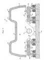
- FIG. 3is a section view of the side elevation view of FIG. 1 .
- FIG. 4is a cross section view taken through the line IV—IV of FIG. 1 , which illustrates one switch of the present invention.
- FIG. 5is a schematic diagram of the electrical layout of the multiple detent switch of the present invention.
- FIG. 1illustrates an embodiment of the multiple detent switch 10 of the present invention.
- the switch 10includes a button 12 having a top wall 14 , a front wall 16 , a rear wall 18 and a plurality of side walls 20 .
- the button 12is open at the bottom and therefore forms a shell.
- the shell-like top 14preferably has one or more projections 22 that aid the driver or user of the switch in pushing, rotating or otherwise moving the button 12 to make one of a plurality of switch closures and thereby activate an automobile function.
- the projections 22 as well as other ergonomic and aesthetic formationsare preferably formed via known injection molding or blow molding techniques, wherein the button 12 is plastic.
- the button 12is alternatively made of any strong, lightweight and easily formed material.
- the button 12may be adapted to have different colors and/or textures or grains in accordance with the use and placement of the switch 10 .
- the button 12 including the projections 22may further be adapted to include indicia that informs the driver or user as to the switch's operation and/or function.
- the button 12is a rocker button that pivotally or rotatably connects to a base 24 .
- the base 24is also preferably molded plastic.
- the connection between the button 12 and the base 24is preferably along a midline of the button 14 as well as a midline of the base 24 .
- the button 12is illustrated as a rocker button, the switch 10 may be adapted to include any type of bi-directional switch.
- the button 12may be adapted to be a toggle button or a thumbwheel, wherein each can be moved or rotated in at least two directions.
- the button 12forms a pair of downwardly projecting flanges 26 on either side 20 of the button.
- the flanges 26are adapted to pivotally connect the button 12 to the base 24 as further illustrated in FIG. 2 .
- the button 12also forms a pair of downwardly projecting tabs 28 on both sides 20 of the button.
- the tabs 28are adapted to pivotally connect a pair of levers 30 a and 30 b to the button 12 .
- the tabs 28each define an aperture 32 , which is sized to receive a lever pivot 34 .
- the lever pivots 34are preferably integrally formed with the levers 30 a and 30 b and thus rotate with resect to the tabs 28 .
- the lever pivots 34are alternatively integrally formed with the tabs 28 so that the levers 30 a and 30 b rotate with respect to the pivots 34 .
- the levers 30 a and 30 beach have an inner end 36 a and 36 b , respectively.
- the levers 30 a and 30 beach have an outer end 38 a and 38 b , respectively.
- Each of the inner ends 36 a and 36 bare adapted to contact inner tactile bridges 40 a and 40 b .
- Each of the outer ends 38 a and 38 bare adapted to contact outer tactile bridges 42 a and 42 b .
- the leverseach have downwardly projecting knobs 44 , which contact the tactile bridges 40 a , 40 b , 40 c and 40 d.
- the base 24includes a plurality of mounts 46 , which are preferably integrally formed with the base.
- each mount 46includes a separate pivot (illustrated in FIG. 2 ) for pivotally or rotatably connecting the button 12 .
- the button 12is thus pivotally held in place by the mounts 46 and supported on either side by a plurality of inner tactile bridges 40 a and 40 b and a plurality of outer tactile bridges 42 a and 42 b . It should be appreciated that the button 12 is constrained from moving unless a driver presses a projection 22 on either the front wall 16 or rear wall 18 end of the button and deforms one or both of the tactile bridges on that end.
- FIG. 2a view from the front wall 16 end of the switch 10 of a cross section taken through the middle of the switch illustrates one embodiment for pivotally attaching the button 12 to the base 24 .
- This viewshows the projection 22 extending upward from the top wall 14 .
- the side walls 20form the flanges 26 as illustrated above.
- the flanges 26each define a button aperture 48 .
- the button aperturesare adapted to receive button pivots 50 , which are integrally formed with the mounts 46 of the base 24 .
- the pivots 50individually snap into or otherwise fit into the apertures 48 of the base 24 , so that the button 12 is constrained to pivot about the button pivots 50 .
- FIG. 2also illustrates the inner end 36 a of the lever 30 a , wherein the lever 30 a includes the knob 44 .
- the knob 44sits on or otherwise contacts the inner tactile bridge 40 a .
- the button 12pivots about the pivots 50 , such that the knob 44 presses against the tactile bridge 40 a .
- Each of the tactile bridges including the bridge 40 ais in one preferred embodiment a deformable piece of conductive material or metal.
- the tactile bridge 40 ahas a slightly rounded shape that is designed to give or flatten out after the application of an amount of force to the outside of the rounded shape. The giving way or flattening out of the circular shape creates a slight snapping or popping sensation, which the driver senses.
- the giving way or flattening out of the circular shapealso creates an electrical contact, i.e., closes a switch, which initiates an automobile function such as running a motor adapted to open or close a window.
- an electrical contacti.e., closes a switch
- an automobile functionsuch as running a motor adapted to open or close a window.
- FIG. 3a lengthwise section of the switch 10 of FIG. 1 is illustrated.
- the section of the button 12includes the top wall 14 , the front wall 16 , rear wall 18 and one side wall 20 .
- the side wall 20includes the flange 26 , which defines the aperture 48 for receiving the button pivot 50 , which is preferably integral to the side wall.
- FIG. 3illustrates the inner side of the wall 20 and therefore shows the button pivot 50 projecting inwardly from the mount 46 , which is attached to the base 24 in back of or outside of the side wall 20 .
- FIG. 3also illustrates the flanges 28 projecting downwardly from the wall 20 in back of or outside of the levers 30 a and 30 b , which have been sectioned.
- the levers 30 a and 30 brespectively include inner walls 36 a and 36 b that face inwardly towards the pivot 50 /aperture 48 interface.
- the levers 30 a and 30 balso respectively include outer walls 38 a and 38 b that face away from the pivot 50 /aperture 48 interface.
- the flanges 28 of wall 20also define the tab apertures 32 (shown in phantom), which receive the lever pivots 34 (shown in phantom).
- the lever pivot 34 /tab aperture 32interfaces, for both levers 30 a and 30 b , are positioned closer to the knobs 44 adjacent to the inner ends 36 a and 36 b than the knobs 44 adjacent to the outer end 38 a and 38 b .
- the pivot 34 /aperture 28 interfacesare positioned twice as close to the inner knobs 44 than to the outer knobs 44 .
- each tactile bridgeis the same, e.g., same material, size and shape, each bridge applies the same resistive force to the pressure exerted through the knobs 44 .
- a lever arm to the outer bridgesi.e., the perpendicular distance from the pivot 34 /aperture 32 interfaces to the outer knobs 44
- the lever arm to the inner bridgesi.e., the perpendicular distance from the pivot 34 /aperture 32 interfaces to the inner knobs 44
- the torque applied by the outer bridgesis greater than the torque applied by the inner bridges. Since torque linearly depends on distance, the disparity of the torque applied by the outer bridges versus the inner bridges is in the same proportion as the disparity between the distances of the lever arms.
- the inner tactile bridges 40 a and 40 balways deform and close their respective switches before the outer tactile bridges 42 a and 42 b deform and close their respective switches, assuming the tactile bridges or other components do not degrade.
- the tactile nature of the bridgesenables the driver to feel the deformation of the inner bridges before the deformation of the outer bridges. That is, the driver can sense when pressing the button 12 a first distance in a first direction causes an automobile function to occur and when pressing the button 12 a second distance in the first direction causes a second function to occur. In the illustrated embodiment, the same tactile sensations occur when the driver presses the button in the other direction. In all, the switch 10 enables the driver to feel four different switch closures.
- the torque disparitywill always cause the outer bridges 42 a and 42 b to return to their formed shape and open their respective switches before the inner bridges 40 a and 40 b .
- the difference in the lever arm distances as well as the spring force of the tactile bridges in one embodimentare chosen so that the driver can operate the functions associated with the inner tactile bridges 40 a and 40 b without necessarily operating the functions associated with the outer tactile bridges 42 a and 42 b .
- Operating the functions associated with the outer tactile bridges, in the illustrated embodimentnecessitates that the inner tactile bridges are also closed.
- the present inventionincludes obtaining the opposite results by positioning the pivot 34 /aperture 32 interfaces closer to the knobs 44 associated with the outer ends 38 a and 38 b and the outer tactile bridges 42 a and 42 b . That is, the driver could operate the functions associated with the outer tactile bridges 42 a and 42 b without necessarily operating the functions associated with the inner tactile bridges 40 a and 40 b . Operating the functions associated with the inner tactile bridges, in this alternative embodiment, necessitates that the outer tactile bridges are also closed.
- the present inventionincludes the provision of two detents or switches in one direction and: (i) no detents or switches in the other direction (two switches total); (ii) one detent or switch in the other direction (three switches total); or (iii) two detents or switches in the other direction (four switches total).
- the switch 10 of the present inventionis adaptable for many uses. Pressing in one direction, the driver can open or close a window at a low via the inner bridge or a high speed via the outer bridge.
- the bridgesmay be adapted to initiate latching coils, so that maintained or latching connections are made. For instance, in one direction the inner bridge initiates a momentary or intermittent window movement, whereby when the driver releases the button, the window stops moving.
- the outer bridgeinitiates a latching circuit that lets the driver release the button while the window slides all the way up or down, wherein a separate limit or position switch senses when the window is totally up or down and opens the latching circuit, cutting current flow to the window motor.
- the inner bridgesinitiate a latching circuit that lets the driver release the button while a function, such as a light, windshield wiper or windshield washer, etc., runs continuously.
- a functionsuch as a light, windshield wiper or windshield washer, etc.
- the switch 10may be adapted to control automobile functions in a momentary or maintained manner including, window movements, mirror movements, windshield wipers, windshield washes, turn signals, radio scans, radios seeks, radio volume and other functions.
- FIG. 4a view from the rear wall 18 end of the switch 10 of a cross section taken through the knob 44 /tactile bridge 40 b interface illustrates the one embodiment for the electrical connection by the bridges to connectors 52 beneath the bridges. That is, FIG. 4 illustrates one embodiment of the switches of the present invention In this view, the section is taken through the projection 22 nearer to the rear end 16 .
- the side walls 20form the flanges 28 as illustrated above.
- the flanges 26define apertures that pivotally receive lever pivots 34 formed integrally with the lever 30 b .
- the lever pivots 34individually snap into or otherwise fit into the apertures of the flanges 28 , so that the lever 30 b is constrained to pivot about the lever pivots 34 .
- the knob 44 formed integrally with the lever 30 bsits atop the inner tactile bridge 40 b .
- the button 12which is substantially supported by the button pivots 50 ( FIG. 2 ) does not compress the bridge 40 b without pressure by the driver or user, and the bridge does not normally make electrical contact with the connectors 52 .
- the connectors 52are imbedded in switch pads 54 and are thereby electrically isolated from the conductive metal bridge 40 b as well as other conductive materials outside the bridge and/or imbedded in the base 24 .
- the connectors 52are in electrical communication with traces, wires or leads imbedded in the base 24 and switch pad 54 .
- the traces, wires or leadsrun to one or more areas or ends of the base 24 , whereby the switch 10 electrically connects to external cables, wires or ribbons, etc., as is well known in the art.
- the knob 44transmits a force to the conductive tactile bridge 40 b , which deforms the bridge so that it physically connects to and electrically communicates with the connectors 52 , closing a switch. Electrical current is then able to flow from a power source (not illustrated) to the switch 10 , through a trace, wire or lead of the switch 10 , through one of the connectors 52 , through the bridge 40 b , through the other connector 52 , through another trace, wire or lead of the switch 10 and out to a load connection of an automobile electrical device.
- the bridge 40 bpops up, no current flows from connector 52 to connector 52 and electrical communication ceases. It should be appreciated that each of the tactile bridges 40 a , 40 b , 42 a and 42 b operates in the same manner.
- the layoutis for the preferred multi-switch embodiment that includes four separate switches and is capable of controlling four different automobile functions.
- the layoutincludes a line trace, lead or wire 56 which connects to an external power source and to one of the connectors 52 of each of the switches designated by the tactile bridge numbers 40 a , 40 b , 42 a and 42 b .
- the layoutincludes four load traces, leads or wires 58 , 60 , 62 and 64 , which connect to external automobile function devices and to the other of the connectors 52 of each of the switches designated by the tactile bridge numbers 40 a , 40 b , 42 a and 42 b.
- a schematic representation of a bell shaped bridge 66(shown in phantom) represents each of the four tactile bridges. If the bell is flattened, i.e., when the knob 44 deforms one of the bridges, the switches 40 a , 40 b , 42 a and 42 b of FIG. 5 are each pushed outward. The inner bridges 40 a and 40 b travel a smaller radial distance to electrically communicate with the connectors 52 of the traces 60 and 62 , respectively, before the outer bridges 42 a and 42 b radially move enough to electrically communicate with the connectors 52 of the traces 58 and 64 , respectively. Thus the load devices 2 and 3 of FIG. 5 will begin to function sooner than will the load devices 1 and 4 . The driver feels the associated tactile sensations for each of the switch connections as described above.
Landscapes
- Rotary Switch, Piano Key Switch, And Lever Switch (AREA)
Abstract
Description
Claims (23)
Priority Applications (1)
| Application Number | Priority Date | Filing Date | Title |
|---|---|---|---|
| US10/721,187US6914201B2 (en) | 2003-11-26 | 2003-11-26 | Multiple detent switch |
Applications Claiming Priority (1)
| Application Number | Priority Date | Filing Date | Title |
|---|---|---|---|
| US10/721,187US6914201B2 (en) | 2003-11-26 | 2003-11-26 | Multiple detent switch |
Publications (2)
| Publication Number | Publication Date |
|---|---|
| US20050109591A1 US20050109591A1 (en) | 2005-05-26 |
| US6914201B2true US6914201B2 (en) | 2005-07-05 |
Family
ID=34591744
Family Applications (1)
| Application Number | Title | Priority Date | Filing Date |
|---|---|---|---|
| US10/721,187Expired - LifetimeUS6914201B2 (en) | 2003-11-26 | 2003-11-26 | Multiple detent switch |
Country Status (1)
| Country | Link |
|---|---|
| US (1) | US6914201B2 (en) |
Cited By (99)
| Publication number | Priority date | Publication date | Assignee | Title |
|---|---|---|---|---|
| US20070051592A1 (en)* | 2005-09-05 | 2007-03-08 | Alps Electric Co., Ltd. | Switch device and steering switch apparatus equipped with the switch device |
| US20080017491A1 (en)* | 2005-12-05 | 2008-01-24 | Farzad Azizi | Electrical switch |
| US20080230360A1 (en)* | 2007-03-20 | 2008-09-25 | Denso Corporation | Rocking switch unit |
| US20080249527A1 (en)* | 2007-04-04 | 2008-10-09 | Tyco Healthcare Group Lp | Electrosurgical instrument reducing current densities at an insulator conductor junction |
| US7708735B2 (en) | 2003-05-01 | 2010-05-04 | Covidien Ag | Incorporating rapid cooling in tissue fusion heating processes |
| US7722607B2 (en) | 2005-09-30 | 2010-05-25 | Covidien Ag | In-line vessel sealer and divider |
| US7771425B2 (en) | 2003-06-13 | 2010-08-10 | Covidien Ag | Vessel sealer and divider having a variable jaw clamping mechanism |
| US7776037B2 (en) | 2006-07-07 | 2010-08-17 | Covidien Ag | System and method for controlling electrode gap during tissue sealing |
| US7776036B2 (en) | 2003-03-13 | 2010-08-17 | Covidien Ag | Bipolar concentric electrode assembly for soft tissue fusion |
| US7789878B2 (en) | 2005-09-30 | 2010-09-07 | Covidien Ag | In-line vessel sealer and divider |
| US7799028B2 (en) | 2004-09-21 | 2010-09-21 | Covidien Ag | Articulating bipolar electrosurgical instrument |
| US7799026B2 (en) | 2002-11-14 | 2010-09-21 | Covidien Ag | Compressible jaw configuration with bipolar RF output electrodes for soft tissue fusion |
| US7811283B2 (en) | 2003-11-19 | 2010-10-12 | Covidien Ag | Open vessel sealing instrument with hourglass cutting mechanism and over-ratchet safety |
| US7828798B2 (en) | 1997-11-14 | 2010-11-09 | Covidien Ag | Laparoscopic bipolar electrosurgical instrument |
| US7846161B2 (en) | 2005-09-30 | 2010-12-07 | Covidien Ag | Insulating boot for electrosurgical forceps |
| US7857812B2 (en) | 2003-06-13 | 2010-12-28 | Covidien Ag | Vessel sealer and divider having elongated knife stroke and safety for cutting mechanism |
| US7877852B2 (en) | 2007-09-20 | 2011-02-01 | Tyco Healthcare Group Lp | Method of manufacturing an end effector assembly for sealing tissue |
| US7877853B2 (en) | 2007-09-20 | 2011-02-01 | Tyco Healthcare Group Lp | Method of manufacturing end effector assembly for sealing tissue |
| US7879035B2 (en) | 2005-09-30 | 2011-02-01 | Covidien Ag | Insulating boot for electrosurgical forceps |
| US7887536B2 (en) | 1998-10-23 | 2011-02-15 | Covidien Ag | Vessel sealing instrument |
| US7909823B2 (en) | 2005-01-14 | 2011-03-22 | Covidien Ag | Open vessel sealing instrument |
| US7922718B2 (en) | 2003-11-19 | 2011-04-12 | Covidien Ag | Open vessel sealing instrument with cutting mechanism |
| US7922953B2 (en) | 2005-09-30 | 2011-04-12 | Covidien Ag | Method for manufacturing an end effector assembly |
| US7931649B2 (en) | 2002-10-04 | 2011-04-26 | Tyco Healthcare Group Lp | Vessel sealing instrument with electrical cutting mechanism |
| US7935052B2 (en) | 2004-09-09 | 2011-05-03 | Covidien Ag | Forceps with spring loaded end effector assembly |
| US7947041B2 (en) | 1998-10-23 | 2011-05-24 | Covidien Ag | Vessel sealing instrument |
| DE102009055669A1 (en)* | 2009-11-25 | 2011-05-26 | Trw Automotive Electronics & Components Gmbh | Electric switch |
| US7951150B2 (en) | 2005-01-14 | 2011-05-31 | Covidien Ag | Vessel sealer and divider with rotating sealer and cutter |
| US7955332B2 (en) | 2004-10-08 | 2011-06-07 | Covidien Ag | Mechanism for dividing tissue in a hemostat-style instrument |
| US7963965B2 (en) | 1997-11-12 | 2011-06-21 | Covidien Ag | Bipolar electrosurgical instrument for sealing vessels |
| US8016827B2 (en) | 2008-10-09 | 2011-09-13 | Tyco Healthcare Group Lp | Apparatus, system, and method for performing an electrosurgical procedure |
| USD649249S1 (en) | 2007-02-15 | 2011-11-22 | Tyco Healthcare Group Lp | End effectors of an elongated dissecting and dividing instrument |
| US8070746B2 (en) | 2006-10-03 | 2011-12-06 | Tyco Healthcare Group Lp | Radiofrequency fusion of cardiac tissue |
| US8142473B2 (en) | 2008-10-03 | 2012-03-27 | Tyco Healthcare Group Lp | Method of transferring rotational motion in an articulating surgical instrument |
| US8162940B2 (en) | 2002-10-04 | 2012-04-24 | Covidien Ag | Vessel sealing instrument with electrical cutting mechanism |
| US8162973B2 (en) | 2008-08-15 | 2012-04-24 | Tyco Healthcare Group Lp | Method of transferring pressure in an articulating surgical instrument |
| US8192433B2 (en) | 2002-10-04 | 2012-06-05 | Covidien Ag | Vessel sealing instrument with electrical cutting mechanism |
| US8197479B2 (en) | 2008-12-10 | 2012-06-12 | Tyco Healthcare Group Lp | Vessel sealer and divider |
| US8211105B2 (en) | 1997-11-12 | 2012-07-03 | Covidien Ag | Electrosurgical instrument which reduces collateral damage to adjacent tissue |
| US8221416B2 (en) | 2007-09-28 | 2012-07-17 | Tyco Healthcare Group Lp | Insulating boot for electrosurgical forceps with thermoplastic clevis |
| US8235992B2 (en) | 2007-09-28 | 2012-08-07 | Tyco Healthcare Group Lp | Insulating boot with mechanical reinforcement for electrosurgical forceps |
| US8236025B2 (en) | 2007-09-28 | 2012-08-07 | Tyco Healthcare Group Lp | Silicone insulated electrosurgical forceps |
| US8235993B2 (en) | 2007-09-28 | 2012-08-07 | Tyco Healthcare Group Lp | Insulating boot for electrosurgical forceps with exohinged structure |
| US8241282B2 (en) | 2006-01-24 | 2012-08-14 | Tyco Healthcare Group Lp | Vessel sealing cutting assemblies |
| US8241283B2 (en) | 2007-09-28 | 2012-08-14 | Tyco Healthcare Group Lp | Dual durometer insulating boot for electrosurgical forceps |
| US8241284B2 (en) | 2001-04-06 | 2012-08-14 | Covidien Ag | Vessel sealer and divider with non-conductive stop members |
| US8251996B2 (en) | 2007-09-28 | 2012-08-28 | Tyco Healthcare Group Lp | Insulating sheath for electrosurgical forceps |
| US8257352B2 (en) | 2003-11-17 | 2012-09-04 | Covidien Ag | Bipolar forceps having monopolar extension |
| US8257387B2 (en) | 2008-08-15 | 2012-09-04 | Tyco Healthcare Group Lp | Method of transferring pressure in an articulating surgical instrument |
| US8267936B2 (en) | 2007-09-28 | 2012-09-18 | Tyco Healthcare Group Lp | Insulating mechanically-interfaced adhesive for electrosurgical forceps |
| US8298232B2 (en) | 2006-01-24 | 2012-10-30 | Tyco Healthcare Group Lp | Endoscopic vessel sealer and divider for large tissue structures |
| US8298228B2 (en) | 1997-11-12 | 2012-10-30 | Coviden Ag | Electrosurgical instrument which reduces collateral damage to adjacent tissue |
| US8303582B2 (en) | 2008-09-15 | 2012-11-06 | Tyco Healthcare Group Lp | Electrosurgical instrument having a coated electrode utilizing an atomic layer deposition technique |
| US8303586B2 (en) | 2003-11-19 | 2012-11-06 | Covidien Ag | Spring loaded reciprocating tissue cutting mechanism in a forceps-style electrosurgical instrument |
| US8317787B2 (en) | 2008-08-28 | 2012-11-27 | Covidien Lp | Tissue fusion jaw angle improvement |
| US8348948B2 (en) | 2004-03-02 | 2013-01-08 | Covidien Ag | Vessel sealing system using capacitive RF dielectric heating |
| US8361071B2 (en) | 1999-10-22 | 2013-01-29 | Covidien Ag | Vessel sealing forceps with disposable electrodes |
| US8382754B2 (en) | 2005-03-31 | 2013-02-26 | Covidien Ag | Electrosurgical forceps with slow closure sealing plates and method of sealing tissue |
| USD680220S1 (en) | 2012-01-12 | 2013-04-16 | Coviden IP | Slider handle for laparoscopic device |
| US8454602B2 (en) | 2009-05-07 | 2013-06-04 | Covidien Lp | Apparatus, system, and method for performing an electrosurgical procedure |
| US8469956B2 (en) | 2008-07-21 | 2013-06-25 | Covidien Lp | Variable resistor jaw |
| US8469957B2 (en) | 2008-10-07 | 2013-06-25 | Covidien Lp | Apparatus, system, and method for performing an electrosurgical procedure |
| US8486107B2 (en) | 2008-10-20 | 2013-07-16 | Covidien Lp | Method of sealing tissue using radiofrequency energy |
| US8496656B2 (en) | 2003-05-15 | 2013-07-30 | Covidien Ag | Tissue sealer with non-conductive variable stop members and method of sealing tissue |
| US8523898B2 (en) | 2009-07-08 | 2013-09-03 | Covidien Lp | Endoscopic electrosurgical jaws with offset knife |
| US8535312B2 (en) | 2008-09-25 | 2013-09-17 | Covidien Lp | Apparatus, system and method for performing an electrosurgical procedure |
| US8591506B2 (en) | 1998-10-23 | 2013-11-26 | Covidien Ag | Vessel sealing system |
| US8597297B2 (en) | 2006-08-29 | 2013-12-03 | Covidien Ag | Vessel sealing instrument with multiple electrode configurations |
| US8623276B2 (en) | 2008-02-15 | 2014-01-07 | Covidien Lp | Method and system for sterilizing an electrosurgical instrument |
| US8636761B2 (en) | 2008-10-09 | 2014-01-28 | Covidien Lp | Apparatus, system, and method for performing an endoscopic electrosurgical procedure |
| US8641713B2 (en) | 2005-09-30 | 2014-02-04 | Covidien Ag | Flexible endoscopic catheter with ligasure |
| US8647341B2 (en) | 2003-06-13 | 2014-02-11 | Covidien Ag | Vessel sealer and divider for use with small trocars and cannulas |
| US8734443B2 (en) | 2006-01-24 | 2014-05-27 | Covidien Lp | Vessel sealer and divider for large tissue structures |
| US8764748B2 (en) | 2008-02-06 | 2014-07-01 | Covidien Lp | End effector assembly for electrosurgical device and method for making the same |
| US8784417B2 (en) | 2008-08-28 | 2014-07-22 | Covidien Lp | Tissue fusion jaw angle improvement |
| US8795274B2 (en) | 2008-08-28 | 2014-08-05 | Covidien Lp | Tissue fusion jaw angle improvement |
| US8852228B2 (en) | 2009-01-13 | 2014-10-07 | Covidien Lp | Apparatus, system, and method for performing an electrosurgical procedure |
| US8882766B2 (en) | 2006-01-24 | 2014-11-11 | Covidien Ag | Method and system for controlling delivery of energy to divide tissue |
| US8898888B2 (en) | 2009-09-28 | 2014-12-02 | Covidien Lp | System for manufacturing electrosurgical seal plates |
| US8968314B2 (en) | 2008-09-25 | 2015-03-03 | Covidien Lp | Apparatus, system and method for performing an electrosurgical procedure |
| US8979208B2 (en)* | 2013-01-08 | 2015-03-17 | Caterpillar Inc. | Transmission and hoist control arrangement |
| US9023043B2 (en) | 2007-09-28 | 2015-05-05 | Covidien Lp | Insulating mechanically-interfaced boot and jaws for electrosurgical forceps |
| US9028493B2 (en) | 2009-09-18 | 2015-05-12 | Covidien Lp | In vivo attachable and detachable end effector assembly and laparoscopic surgical instrument and methods therefor |
| US9095347B2 (en) | 2003-11-20 | 2015-08-04 | Covidien Ag | Electrically conductive/insulative over shoe for tissue fusion |
| US9107672B2 (en) | 1998-10-23 | 2015-08-18 | Covidien Ag | Vessel sealing forceps with disposable electrodes |
| US9113940B2 (en) | 2011-01-14 | 2015-08-25 | Covidien Lp | Trigger lockout and kickback mechanism for surgical instruments |
| US9149323B2 (en) | 2003-05-01 | 2015-10-06 | Covidien Ag | Method of fusing biomaterials with radiofrequency energy |
| US9375254B2 (en) | 2008-09-25 | 2016-06-28 | Covidien Lp | Seal and separate algorithm |
| US9603652B2 (en) | 2008-08-21 | 2017-03-28 | Covidien Lp | Electrosurgical instrument including a sensor |
| US9848938B2 (en) | 2003-11-13 | 2017-12-26 | Covidien Ag | Compressible jaw configuration with bipolar RF output electrodes for soft tissue fusion |
| US20180283100A1 (en)* | 2015-06-15 | 2018-10-04 | David R. Hall | Retractable privacy system and method |
| US10213250B2 (en) | 2015-11-05 | 2019-02-26 | Covidien Lp | Deployment and safety mechanisms for surgical instruments |
| US10231777B2 (en) | 2014-08-26 | 2019-03-19 | Covidien Lp | Methods of manufacturing jaw members of an end-effector assembly for a surgical instrument |
| US10646267B2 (en) | 2013-08-07 | 2020-05-12 | Covidien LLP | Surgical forceps |
| US10987159B2 (en) | 2015-08-26 | 2021-04-27 | Covidien Lp | Electrosurgical end effector assemblies and electrosurgical forceps configured to reduce thermal spread |
| US11166759B2 (en) | 2017-05-16 | 2021-11-09 | Covidien Lp | Surgical forceps |
| USD956973S1 (en) | 2003-06-13 | 2022-07-05 | Covidien Ag | Movable handle for endoscopic vessel sealer and divider |
| US11682535B2 (en) | 2021-03-12 | 2023-06-20 | Essex Industries, Inc. | Rocker switch |
| US11688568B2 (en) | 2021-03-15 | 2023-06-27 | Essex Industries, Inc. | Five-position switch |
Families Citing this family (4)
| Publication number | Priority date | Publication date | Assignee | Title |
|---|---|---|---|---|
| FR2874229B1 (en)* | 2004-08-10 | 2006-11-24 | Somfy Sas | METHOD OF OPERATING A CONTROLLED AND POWERED ROLLING SHUTTER THROUGH A WIRED CONTROL INTERFACE |
| US9955594B2 (en)* | 2015-07-13 | 2018-04-24 | Denso Wave Incorporated | Operation device |
| US9981632B2 (en)* | 2016-07-28 | 2018-05-29 | GM Global Technology Operations LLC | Systems for electrically isolating an electronic module from a front windshield and a rear window washer |
| EP3312863B1 (en)* | 2016-10-24 | 2019-07-31 | Dav | Switch device in particular for a use in a push pull window lifter mechanism |
Citations (7)
| Publication number | Priority date | Publication date | Assignee | Title |
|---|---|---|---|---|
| US5598918A (en)* | 1995-05-18 | 1997-02-04 | Trw Inc. | Switch for vehicle power window |
| US5693920A (en)* | 1994-10-07 | 1997-12-02 | Alps Electric Co., Ltd. | Two-stage movement seesaw switch apparatus |
| US5719361A (en)* | 1996-08-09 | 1998-02-17 | Packard Hughes Interconnect Company | Mechanism for multiple dome dual detent |
| US5753874A (en)* | 1996-01-10 | 1998-05-19 | Leopold Kostal Gmbh & Co. Kg | Rocker member actuated switch assembly |
| US5834716A (en)* | 1996-08-09 | 1998-11-10 | Packard Hughes Interconnect Company | Four position two dome switch |
| US6437259B1 (en)* | 1999-03-18 | 2002-08-20 | Delphi Technologies, Inc. | Switch for a pop-up/sliding roof |
| US6693246B1 (en)* | 1999-09-25 | 2004-02-17 | Delphi Technologies, Inc. | Rocker switch for one two-stage actuating stroke |
- 2003
- 2003-11-26USUS10/721,187patent/US6914201B2/ennot_activeExpired - Lifetime
Patent Citations (7)
| Publication number | Priority date | Publication date | Assignee | Title |
|---|---|---|---|---|
| US5693920A (en)* | 1994-10-07 | 1997-12-02 | Alps Electric Co., Ltd. | Two-stage movement seesaw switch apparatus |
| US5598918A (en)* | 1995-05-18 | 1997-02-04 | Trw Inc. | Switch for vehicle power window |
| US5753874A (en)* | 1996-01-10 | 1998-05-19 | Leopold Kostal Gmbh & Co. Kg | Rocker member actuated switch assembly |
| US5719361A (en)* | 1996-08-09 | 1998-02-17 | Packard Hughes Interconnect Company | Mechanism for multiple dome dual detent |
| US5834716A (en)* | 1996-08-09 | 1998-11-10 | Packard Hughes Interconnect Company | Four position two dome switch |
| US6437259B1 (en)* | 1999-03-18 | 2002-08-20 | Delphi Technologies, Inc. | Switch for a pop-up/sliding roof |
| US6693246B1 (en)* | 1999-09-25 | 2004-02-17 | Delphi Technologies, Inc. | Rocker switch for one two-stage actuating stroke |
Cited By (162)
| Publication number | Priority date | Publication date | Assignee | Title |
|---|---|---|---|---|
| US8211105B2 (en) | 1997-11-12 | 2012-07-03 | Covidien Ag | Electrosurgical instrument which reduces collateral damage to adjacent tissue |
| US7963965B2 (en) | 1997-11-12 | 2011-06-21 | Covidien Ag | Bipolar electrosurgical instrument for sealing vessels |
| US8298228B2 (en) | 1997-11-12 | 2012-10-30 | Coviden Ag | Electrosurgical instrument which reduces collateral damage to adjacent tissue |
| US7828798B2 (en) | 1997-11-14 | 2010-11-09 | Covidien Ag | Laparoscopic bipolar electrosurgical instrument |
| US9375270B2 (en) | 1998-10-23 | 2016-06-28 | Covidien Ag | Vessel sealing system |
| US8591506B2 (en) | 1998-10-23 | 2013-11-26 | Covidien Ag | Vessel sealing system |
| US9107672B2 (en) | 1998-10-23 | 2015-08-18 | Covidien Ag | Vessel sealing forceps with disposable electrodes |
| US9375271B2 (en) | 1998-10-23 | 2016-06-28 | Covidien Ag | Vessel sealing system |
| US9463067B2 (en) | 1998-10-23 | 2016-10-11 | Covidien Ag | Vessel sealing system |
| US7947041B2 (en) | 1998-10-23 | 2011-05-24 | Covidien Ag | Vessel sealing instrument |
| US7896878B2 (en) | 1998-10-23 | 2011-03-01 | Coviden Ag | Vessel sealing instrument |
| US7887536B2 (en) | 1998-10-23 | 2011-02-15 | Covidien Ag | Vessel sealing instrument |
| US8361071B2 (en) | 1999-10-22 | 2013-01-29 | Covidien Ag | Vessel sealing forceps with disposable electrodes |
| US10687887B2 (en) | 2001-04-06 | 2020-06-23 | Covidien Ag | Vessel sealer and divider |
| US10265121B2 (en) | 2001-04-06 | 2019-04-23 | Covidien Ag | Vessel sealer and divider |
| US8241284B2 (en) | 2001-04-06 | 2012-08-14 | Covidien Ag | Vessel sealer and divider with non-conductive stop members |
| US10251696B2 (en) | 2001-04-06 | 2019-04-09 | Covidien Ag | Vessel sealer and divider with stop members |
| US8192433B2 (en) | 2002-10-04 | 2012-06-05 | Covidien Ag | Vessel sealing instrument with electrical cutting mechanism |
| US8740901B2 (en) | 2002-10-04 | 2014-06-03 | Covidien Ag | Vessel sealing instrument with electrical cutting mechanism |
| US10987160B2 (en) | 2002-10-04 | 2021-04-27 | Covidien Ag | Vessel sealing instrument with cutting mechanism |
| US8551091B2 (en) | 2002-10-04 | 2013-10-08 | Covidien Ag | Vessel sealing instrument with electrical cutting mechanism |
| US8162940B2 (en) | 2002-10-04 | 2012-04-24 | Covidien Ag | Vessel sealing instrument with electrical cutting mechanism |
| US7931649B2 (en) | 2002-10-04 | 2011-04-26 | Tyco Healthcare Group Lp | Vessel sealing instrument with electrical cutting mechanism |
| US8333765B2 (en) | 2002-10-04 | 2012-12-18 | Covidien Ag | Vessel sealing instrument with electrical cutting mechanism |
| US9585716B2 (en) | 2002-10-04 | 2017-03-07 | Covidien Ag | Vessel sealing instrument with electrical cutting mechanism |
| US10537384B2 (en) | 2002-10-04 | 2020-01-21 | Covidien Lp | Vessel sealing instrument with electrical cutting mechanism |
| US7799026B2 (en) | 2002-11-14 | 2010-09-21 | Covidien Ag | Compressible jaw configuration with bipolar RF output electrodes for soft tissue fusion |
| US8945125B2 (en) | 2002-11-14 | 2015-02-03 | Covidien Ag | Compressible jaw configuration with bipolar RF output electrodes for soft tissue fusion |
| US7776036B2 (en) | 2003-03-13 | 2010-08-17 | Covidien Ag | Bipolar concentric electrode assembly for soft tissue fusion |
| US9149323B2 (en) | 2003-05-01 | 2015-10-06 | Covidien Ag | Method of fusing biomaterials with radiofrequency energy |
| US8679114B2 (en) | 2003-05-01 | 2014-03-25 | Covidien Ag | Incorporating rapid cooling in tissue fusion heating processes |
| US7708735B2 (en) | 2003-05-01 | 2010-05-04 | Covidien Ag | Incorporating rapid cooling in tissue fusion heating processes |
| USRE47375E1 (en) | 2003-05-15 | 2019-05-07 | Coviden Ag | Tissue sealer with non-conductive variable stop members and method of sealing tissue |
| US8496656B2 (en) | 2003-05-15 | 2013-07-30 | Covidien Ag | Tissue sealer with non-conductive variable stop members and method of sealing tissue |
| US9492225B2 (en) | 2003-06-13 | 2016-11-15 | Covidien Ag | Vessel sealer and divider for use with small trocars and cannulas |
| US8647341B2 (en) | 2003-06-13 | 2014-02-11 | Covidien Ag | Vessel sealer and divider for use with small trocars and cannulas |
| US7771425B2 (en) | 2003-06-13 | 2010-08-10 | Covidien Ag | Vessel sealer and divider having a variable jaw clamping mechanism |
| US10918435B2 (en) | 2003-06-13 | 2021-02-16 | Covidien Ag | Vessel sealer and divider |
| US7857812B2 (en) | 2003-06-13 | 2010-12-28 | Covidien Ag | Vessel sealer and divider having elongated knife stroke and safety for cutting mechanism |
| US10278772B2 (en) | 2003-06-13 | 2019-05-07 | Covidien Ag | Vessel sealer and divider |
| USD956973S1 (en) | 2003-06-13 | 2022-07-05 | Covidien Ag | Movable handle for endoscopic vessel sealer and divider |
| US10842553B2 (en) | 2003-06-13 | 2020-11-24 | Covidien Ag | Vessel sealer and divider |
| US9848938B2 (en) | 2003-11-13 | 2017-12-26 | Covidien Ag | Compressible jaw configuration with bipolar RF output electrodes for soft tissue fusion |
| US10441350B2 (en) | 2003-11-17 | 2019-10-15 | Covidien Ag | Bipolar forceps having monopolar extension |
| US8597296B2 (en) | 2003-11-17 | 2013-12-03 | Covidien Ag | Bipolar forceps having monopolar extension |
| US8257352B2 (en) | 2003-11-17 | 2012-09-04 | Covidien Ag | Bipolar forceps having monopolar extension |
| US7922718B2 (en) | 2003-11-19 | 2011-04-12 | Covidien Ag | Open vessel sealing instrument with cutting mechanism |
| US8394096B2 (en) | 2003-11-19 | 2013-03-12 | Covidien Ag | Open vessel sealing instrument with cutting mechanism |
| US8623017B2 (en) | 2003-11-19 | 2014-01-07 | Covidien Ag | Open vessel sealing instrument with hourglass cutting mechanism and overratchet safety |
| US8303586B2 (en) | 2003-11-19 | 2012-11-06 | Covidien Ag | Spring loaded reciprocating tissue cutting mechanism in a forceps-style electrosurgical instrument |
| US7811283B2 (en) | 2003-11-19 | 2010-10-12 | Covidien Ag | Open vessel sealing instrument with hourglass cutting mechanism and over-ratchet safety |
| US9095347B2 (en) | 2003-11-20 | 2015-08-04 | Covidien Ag | Electrically conductive/insulative over shoe for tissue fusion |
| US9980770B2 (en) | 2003-11-20 | 2018-05-29 | Covidien Ag | Electrically conductive/insulative over-shoe for tissue fusion |
| US8348948B2 (en) | 2004-03-02 | 2013-01-08 | Covidien Ag | Vessel sealing system using capacitive RF dielectric heating |
| US7935052B2 (en) | 2004-09-09 | 2011-05-03 | Covidien Ag | Forceps with spring loaded end effector assembly |
| US8366709B2 (en) | 2004-09-21 | 2013-02-05 | Covidien Ag | Articulating bipolar electrosurgical instrument |
| US7799028B2 (en) | 2004-09-21 | 2010-09-21 | Covidien Ag | Articulating bipolar electrosurgical instrument |
| US8123743B2 (en) | 2004-10-08 | 2012-02-28 | Covidien Ag | Mechanism for dividing tissue in a hemostat-style instrument |
| US7955332B2 (en) | 2004-10-08 | 2011-06-07 | Covidien Ag | Mechanism for dividing tissue in a hemostat-style instrument |
| US8147489B2 (en) | 2005-01-14 | 2012-04-03 | Covidien Ag | Open vessel sealing instrument |
| US7951150B2 (en) | 2005-01-14 | 2011-05-31 | Covidien Ag | Vessel sealer and divider with rotating sealer and cutter |
| US7909823B2 (en) | 2005-01-14 | 2011-03-22 | Covidien Ag | Open vessel sealing instrument |
| US8382754B2 (en) | 2005-03-31 | 2013-02-26 | Covidien Ag | Electrosurgical forceps with slow closure sealing plates and method of sealing tissue |
| US7439459B2 (en)* | 2005-09-05 | 2008-10-21 | Alps Electric Co., Ltd. | Switch device and steering switch apparatus equipped with the switch device |
| US20070051592A1 (en)* | 2005-09-05 | 2007-03-08 | Alps Electric Co., Ltd. | Switch device and steering switch apparatus equipped with the switch device |
| US8394095B2 (en) | 2005-09-30 | 2013-03-12 | Covidien Ag | Insulating boot for electrosurgical forceps |
| US7846161B2 (en) | 2005-09-30 | 2010-12-07 | Covidien Ag | Insulating boot for electrosurgical forceps |
| US7922953B2 (en) | 2005-09-30 | 2011-04-12 | Covidien Ag | Method for manufacturing an end effector assembly |
| US7879035B2 (en) | 2005-09-30 | 2011-02-01 | Covidien Ag | Insulating boot for electrosurgical forceps |
| US9579145B2 (en) | 2005-09-30 | 2017-02-28 | Covidien Ag | Flexible endoscopic catheter with ligasure |
| US7722607B2 (en) | 2005-09-30 | 2010-05-25 | Covidien Ag | In-line vessel sealer and divider |
| US8641713B2 (en) | 2005-09-30 | 2014-02-04 | Covidien Ag | Flexible endoscopic catheter with ligasure |
| US8361072B2 (en) | 2005-09-30 | 2013-01-29 | Covidien Ag | Insulating boot for electrosurgical forceps |
| US7789878B2 (en) | 2005-09-30 | 2010-09-07 | Covidien Ag | In-line vessel sealer and divider |
| USRE44834E1 (en) | 2005-09-30 | 2014-04-08 | Covidien Ag | Insulating boot for electrosurgical forceps |
| US8197633B2 (en) | 2005-09-30 | 2012-06-12 | Covidien Ag | Method for manufacturing an end effector assembly |
| US9549775B2 (en) | 2005-09-30 | 2017-01-24 | Covidien Ag | In-line vessel sealer and divider |
| US8668689B2 (en) | 2005-09-30 | 2014-03-11 | Covidien Ag | In-line vessel sealer and divider |
| US7507923B2 (en)* | 2005-12-05 | 2009-03-24 | Omron Dualtec Automotive Electronics Inc. | Electrical switch |
| US20080017491A1 (en)* | 2005-12-05 | 2008-01-24 | Farzad Azizi | Electrical switch |
| US9918782B2 (en) | 2006-01-24 | 2018-03-20 | Covidien Lp | Endoscopic vessel sealer and divider for large tissue structures |
| US9113903B2 (en) | 2006-01-24 | 2015-08-25 | Covidien Lp | Endoscopic vessel sealer and divider for large tissue structures |
| US9539053B2 (en) | 2006-01-24 | 2017-01-10 | Covidien Lp | Vessel sealer and divider for large tissue structures |
| US8734443B2 (en) | 2006-01-24 | 2014-05-27 | Covidien Lp | Vessel sealer and divider for large tissue structures |
| US8298232B2 (en) | 2006-01-24 | 2012-10-30 | Tyco Healthcare Group Lp | Endoscopic vessel sealer and divider for large tissue structures |
| US8882766B2 (en) | 2006-01-24 | 2014-11-11 | Covidien Ag | Method and system for controlling delivery of energy to divide tissue |
| US8241282B2 (en) | 2006-01-24 | 2012-08-14 | Tyco Healthcare Group Lp | Vessel sealing cutting assemblies |
| US7776037B2 (en) | 2006-07-07 | 2010-08-17 | Covidien Ag | System and method for controlling electrode gap during tissue sealing |
| US8597297B2 (en) | 2006-08-29 | 2013-12-03 | Covidien Ag | Vessel sealing instrument with multiple electrode configurations |
| US8070746B2 (en) | 2006-10-03 | 2011-12-06 | Tyco Healthcare Group Lp | Radiofrequency fusion of cardiac tissue |
| US8425504B2 (en) | 2006-10-03 | 2013-04-23 | Covidien Lp | Radiofrequency fusion of cardiac tissue |
| USD649249S1 (en) | 2007-02-15 | 2011-11-22 | Tyco Healthcare Group Lp | End effectors of an elongated dissecting and dividing instrument |
| US20080230360A1 (en)* | 2007-03-20 | 2008-09-25 | Denso Corporation | Rocking switch unit |
| US7554049B2 (en)* | 2007-03-20 | 2009-06-30 | Denso Corporation | Rocking switch unit |
| US20080249527A1 (en)* | 2007-04-04 | 2008-10-09 | Tyco Healthcare Group Lp | Electrosurgical instrument reducing current densities at an insulator conductor junction |
| US8267935B2 (en) | 2007-04-04 | 2012-09-18 | Tyco Healthcare Group Lp | Electrosurgical instrument reducing current densities at an insulator conductor junction |
| US7877852B2 (en) | 2007-09-20 | 2011-02-01 | Tyco Healthcare Group Lp | Method of manufacturing an end effector assembly for sealing tissue |
| US7877853B2 (en) | 2007-09-20 | 2011-02-01 | Tyco Healthcare Group Lp | Method of manufacturing end effector assembly for sealing tissue |
| US8267936B2 (en) | 2007-09-28 | 2012-09-18 | Tyco Healthcare Group Lp | Insulating mechanically-interfaced adhesive for electrosurgical forceps |
| US8236025B2 (en) | 2007-09-28 | 2012-08-07 | Tyco Healthcare Group Lp | Silicone insulated electrosurgical forceps |
| US8235992B2 (en) | 2007-09-28 | 2012-08-07 | Tyco Healthcare Group Lp | Insulating boot with mechanical reinforcement for electrosurgical forceps |
| US8696667B2 (en) | 2007-09-28 | 2014-04-15 | Covidien Lp | Dual durometer insulating boot for electrosurgical forceps |
| US9554841B2 (en) | 2007-09-28 | 2017-01-31 | Covidien Lp | Dual durometer insulating boot for electrosurgical forceps |
| US8241283B2 (en) | 2007-09-28 | 2012-08-14 | Tyco Healthcare Group Lp | Dual durometer insulating boot for electrosurgical forceps |
| US8221416B2 (en) | 2007-09-28 | 2012-07-17 | Tyco Healthcare Group Lp | Insulating boot for electrosurgical forceps with thermoplastic clevis |
| US8251996B2 (en) | 2007-09-28 | 2012-08-28 | Tyco Healthcare Group Lp | Insulating sheath for electrosurgical forceps |
| US9023043B2 (en) | 2007-09-28 | 2015-05-05 | Covidien Lp | Insulating mechanically-interfaced boot and jaws for electrosurgical forceps |
| US8235993B2 (en) | 2007-09-28 | 2012-08-07 | Tyco Healthcare Group Lp | Insulating boot for electrosurgical forceps with exohinged structure |
| US8764748B2 (en) | 2008-02-06 | 2014-07-01 | Covidien Lp | End effector assembly for electrosurgical device and method for making the same |
| US8623276B2 (en) | 2008-02-15 | 2014-01-07 | Covidien Lp | Method and system for sterilizing an electrosurgical instrument |
| US9113905B2 (en) | 2008-07-21 | 2015-08-25 | Covidien Lp | Variable resistor jaw |
| US8469956B2 (en) | 2008-07-21 | 2013-06-25 | Covidien Lp | Variable resistor jaw |
| US9247988B2 (en) | 2008-07-21 | 2016-02-02 | Covidien Lp | Variable resistor jaw |
| US8257387B2 (en) | 2008-08-15 | 2012-09-04 | Tyco Healthcare Group Lp | Method of transferring pressure in an articulating surgical instrument |
| US8162973B2 (en) | 2008-08-15 | 2012-04-24 | Tyco Healthcare Group Lp | Method of transferring pressure in an articulating surgical instrument |
| US9603652B2 (en) | 2008-08-21 | 2017-03-28 | Covidien Lp | Electrosurgical instrument including a sensor |
| US8784417B2 (en) | 2008-08-28 | 2014-07-22 | Covidien Lp | Tissue fusion jaw angle improvement |
| US8317787B2 (en) | 2008-08-28 | 2012-11-27 | Covidien Lp | Tissue fusion jaw angle improvement |
| US8795274B2 (en) | 2008-08-28 | 2014-08-05 | Covidien Lp | Tissue fusion jaw angle improvement |
| US8303582B2 (en) | 2008-09-15 | 2012-11-06 | Tyco Healthcare Group Lp | Electrosurgical instrument having a coated electrode utilizing an atomic layer deposition technique |
| US8535312B2 (en) | 2008-09-25 | 2013-09-17 | Covidien Lp | Apparatus, system and method for performing an electrosurgical procedure |
| US8968314B2 (en) | 2008-09-25 | 2015-03-03 | Covidien Lp | Apparatus, system and method for performing an electrosurgical procedure |
| US9375254B2 (en) | 2008-09-25 | 2016-06-28 | Covidien Lp | Seal and separate algorithm |
| US8142473B2 (en) | 2008-10-03 | 2012-03-27 | Tyco Healthcare Group Lp | Method of transferring rotational motion in an articulating surgical instrument |
| US8568444B2 (en) | 2008-10-03 | 2013-10-29 | Covidien Lp | Method of transferring rotational motion in an articulating surgical instrument |
| US8469957B2 (en) | 2008-10-07 | 2013-06-25 | Covidien Lp | Apparatus, system, and method for performing an electrosurgical procedure |
| US8016827B2 (en) | 2008-10-09 | 2011-09-13 | Tyco Healthcare Group Lp | Apparatus, system, and method for performing an electrosurgical procedure |
| US9113898B2 (en) | 2008-10-09 | 2015-08-25 | Covidien Lp | Apparatus, system, and method for performing an electrosurgical procedure |
| US8636761B2 (en) | 2008-10-09 | 2014-01-28 | Covidien Lp | Apparatus, system, and method for performing an endoscopic electrosurgical procedure |
| US8486107B2 (en) | 2008-10-20 | 2013-07-16 | Covidien Lp | Method of sealing tissue using radiofrequency energy |
| US8197479B2 (en) | 2008-12-10 | 2012-06-12 | Tyco Healthcare Group Lp | Vessel sealer and divider |
| US8852228B2 (en) | 2009-01-13 | 2014-10-07 | Covidien Lp | Apparatus, system, and method for performing an electrosurgical procedure |
| US9655674B2 (en) | 2009-01-13 | 2017-05-23 | Covidien Lp | Apparatus, system and method for performing an electrosurgical procedure |
| US8454602B2 (en) | 2009-05-07 | 2013-06-04 | Covidien Lp | Apparatus, system, and method for performing an electrosurgical procedure |
| US10085794B2 (en) | 2009-05-07 | 2018-10-02 | Covidien Lp | Apparatus, system and method for performing an electrosurgical procedure |
| US9345535B2 (en) | 2009-05-07 | 2016-05-24 | Covidien Lp | Apparatus, system and method for performing an electrosurgical procedure |
| US8858554B2 (en) | 2009-05-07 | 2014-10-14 | Covidien Lp | Apparatus, system, and method for performing an electrosurgical procedure |
| US8523898B2 (en) | 2009-07-08 | 2013-09-03 | Covidien Lp | Endoscopic electrosurgical jaws with offset knife |
| US9028493B2 (en) | 2009-09-18 | 2015-05-12 | Covidien Lp | In vivo attachable and detachable end effector assembly and laparoscopic surgical instrument and methods therefor |
| US9931131B2 (en) | 2009-09-18 | 2018-04-03 | Covidien Lp | In vivo attachable and detachable end effector assembly and laparoscopic surgical instrument and methods therefor |
| US11490955B2 (en) | 2009-09-28 | 2022-11-08 | Covidien Lp | Electrosurgical seal plates |
| US11026741B2 (en) | 2009-09-28 | 2021-06-08 | Covidien Lp | Electrosurgical seal plates |
| US9750561B2 (en) | 2009-09-28 | 2017-09-05 | Covidien Lp | System for manufacturing electrosurgical seal plates |
| US10188454B2 (en) | 2009-09-28 | 2019-01-29 | Covidien Lp | System for manufacturing electrosurgical seal plates |
| US9265552B2 (en) | 2009-09-28 | 2016-02-23 | Covidien Lp | Method of manufacturing electrosurgical seal plates |
| US8898888B2 (en) | 2009-09-28 | 2014-12-02 | Covidien Lp | System for manufacturing electrosurgical seal plates |
| DE102009055669A1 (en)* | 2009-11-25 | 2011-05-26 | Trw Automotive Electronics & Components Gmbh | Electric switch |
| US8816229B2 (en) | 2009-11-25 | 2014-08-26 | Trw Automotive Electronics & Components Gmbh | Electrical switch |
| US11660108B2 (en) | 2011-01-14 | 2023-05-30 | Covidien Lp | Trigger lockout and kickback mechanism for surgical instruments |
| US9113940B2 (en) | 2011-01-14 | 2015-08-25 | Covidien Lp | Trigger lockout and kickback mechanism for surgical instruments |
| US10383649B2 (en) | 2011-01-14 | 2019-08-20 | Covidien Lp | Trigger lockout and kickback mechanism for surgical instruments |
| USD680220S1 (en) | 2012-01-12 | 2013-04-16 | Coviden IP | Slider handle for laparoscopic device |
| US8979208B2 (en)* | 2013-01-08 | 2015-03-17 | Caterpillar Inc. | Transmission and hoist control arrangement |
| US10646267B2 (en) | 2013-08-07 | 2020-05-12 | Covidien LLP | Surgical forceps |
| US10231777B2 (en) | 2014-08-26 | 2019-03-19 | Covidien Lp | Methods of manufacturing jaw members of an end-effector assembly for a surgical instrument |
| US20180283100A1 (en)* | 2015-06-15 | 2018-10-04 | David R. Hall | Retractable privacy system and method |
| US10987159B2 (en) | 2015-08-26 | 2021-04-27 | Covidien Lp | Electrosurgical end effector assemblies and electrosurgical forceps configured to reduce thermal spread |
| US10213250B2 (en) | 2015-11-05 | 2019-02-26 | Covidien Lp | Deployment and safety mechanisms for surgical instruments |
| US11166759B2 (en) | 2017-05-16 | 2021-11-09 | Covidien Lp | Surgical forceps |
| US11682535B2 (en) | 2021-03-12 | 2023-06-20 | Essex Industries, Inc. | Rocker switch |
| US11688568B2 (en) | 2021-03-15 | 2023-06-27 | Essex Industries, Inc. | Five-position switch |
| US12046429B2 (en) | 2021-03-15 | 2024-07-23 | Essex Industries, Inc. | Five-position switch |
Also Published As
| Publication number | Publication date |
|---|---|
| US20050109591A1 (en) | 2005-05-26 |
Similar Documents
| Publication | Publication Date | Title |
|---|---|---|
| US6914201B2 (en) | Multiple detent switch | |
| US5559311A (en) | Dual detent dome switch assembly | |
| US6635832B1 (en) | Electrical switch | |
| CN100533625C (en) | switchgear | |
| US6180903B1 (en) | Tact Switch | |
| US4737609A (en) | Push button switch | |
| US5610378A (en) | Steering column stalk switch apparatus | |
| US5720379A (en) | Push-push switch with lock | |
| JP2000512072A (en) | Switching device having secondary switching function | |
| US6260431B1 (en) | Construction of an on-vehicle lever switch | |
| JP3108011B2 (en) | Device for controlling the movement of the power window | |
| US6384351B1 (en) | Switch apparatus for actuating a plurality of electrical circuits | |
| US5336859A (en) | Illuminated switch | |
| US6329898B1 (en) | Multiple operation type electrical part | |
| EP1380040B1 (en) | Multifunctional windshield wiper stalk switch | |
| JP2000208003A (en) | Lever switch device | |
| US5622254A (en) | Two-position latching two dome switch | |
| JP3152118B2 (en) | Switch device | |
| EP1090807A2 (en) | Lever switch | |
| US6756556B2 (en) | Oscillating switch | |
| US5107085A (en) | Clustered push button switches having sheet metal conductors formed with contact tabs | |
| EP1739792B1 (en) | Circuit unit device | |
| GB1604432A (en) | Electrical switch combination | |
| US20020121431A1 (en) | Electrical switch for vehicle lighting | |
| US4398168A (en) | Switching mechanism |
Legal Events
| Date | Code | Title | Description |
|---|---|---|---|
| AS | Assignment | Owner name:METHOD ELECTRONICS, INC., ILLINOIS Free format text:ASSIGNMENT OF ASSIGNORS INTEREST;ASSIGNOR:VAN VOOREN, GREGORY P.;REEL/FRAME:015534/0860 Effective date:20031029 | |
| AS | Assignment | Owner name:METHOD ELECTRONICS, INC., ILLINOIS Free format text:ASSIGNMENT OF ASSIGNORS INTEREST;ASSIGNOR:VANVOOREN, GREGORY P.;REEL/FRAME:015855/0372 Effective date:20031029 | |
| AS | Assignment | Owner name:METHODE ELECTRONICS, INC., ILLINOIS Free format text:CORRECTED ASSIGNMENT RECORDATION COVER SHEET TO CORRECT ERROR ON NOTICE OF RECORDATION RECORDED;ASSIGNOR:VAN VOOREN, GREGORY P.;REEL/FRAME:016543/0744 Effective date:20031029 | |
| AS | Assignment | Owner name:METHODE ELECTRONICS, INC., ILLINOIS Free format text:CORRECTED ASSIGNMENT RECORDATION COVER SHEET TO CORRECT ERROR ON NOTICE OF RECORDATION REEL/FRAME 015855/0372;ASSIGNOR:VAN VOOREN, GREGORY P.;REEL/FRAME:016370/0117 Effective date:20031029 | |
| STCF | Information on status: patent grant | Free format text:PATENTED CASE | |
| FPAY | Fee payment | Year of fee payment:4 | |
| FPAY | Fee payment | Year of fee payment:8 | |
| FPAY | Fee payment | Year of fee payment:12 |