US6913595B2 - Medical device and locking mechanism therefor - Google Patents
Medical device and locking mechanism thereforDownload PDFInfo
- Publication number
- US6913595B2 US6913595B2US10/069,688US6968802AUS6913595B2US 6913595 B2US6913595 B2US 6913595B2US 6968802 AUS6968802 AUS 6968802AUS 6913595 B2US6913595 B2US 6913595B2
- Authority
- US
- United States
- Prior art keywords
- locking mechanism
- connector
- retainer
- legs
- medical device
- Prior art date
- Legal status (The legal status is an assumption and is not a legal conclusion. Google has not performed a legal analysis and makes no representation as to the accuracy of the status listed.)
- Expired - Lifetime, expires
Links
- 230000007246mechanismEffects0.000titleclaimsabstractdescription74
- 230000015572biosynthetic processEffects0.000claimsdescription26
- 229910003460diamondInorganic materials0.000claimsdescription6
- 239000010432diamondSubstances0.000claimsdescription6
- 238000003780insertionMethods0.000claimsdescription3
- 230000037431insertionEffects0.000claimsdescription3
- 238000005755formation reactionMethods0.000claims18
- 239000012530fluidSubstances0.000description19
- 239000000463materialSubstances0.000description12
- 230000008901benefitEffects0.000description8
- 238000002347injectionMethods0.000description8
- 239000007924injectionSubstances0.000description8
- 230000000994depressogenic effectEffects0.000description7
- 239000003292glueSubstances0.000description7
- 239000003814drugSubstances0.000description6
- 238000007789sealingMethods0.000description6
- 230000000712assemblyEffects0.000description5
- 238000000429assemblyMethods0.000description5
- 229910000831SteelInorganic materials0.000description4
- 239000008280bloodSubstances0.000description4
- 210000004369bloodAnatomy0.000description4
- 238000000034methodMethods0.000description4
- 239000010959steelSubstances0.000description4
- 208000012266Needlestick injuryDiseases0.000description3
- 208000015181infectious diseaseDiseases0.000description3
- 230000000717retained effectEffects0.000description3
- 238000005452bendingMethods0.000description2
- 230000005540biological transmissionEffects0.000description2
- 238000000605extractionMethods0.000description2
- 230000004048modificationEffects0.000description2
- 238000012986modificationMethods0.000description2
- 102000004169proteins and genesHuman genes0.000description2
- 108090000623proteins and genesProteins0.000description2
- 206010006500BrucellosisDiseases0.000description1
- 241001631457CannulaSpecies0.000description1
- 241000219104CucurbitaceaeSpecies0.000description1
- 201000011001Ebola Hemorrhagic FeverDiseases0.000description1
- IAYPIBMASNFSPL-UHFFFAOYSA-NEthylene oxideChemical compoundC1CO1IAYPIBMASNFSPL-UHFFFAOYSA-N0.000description1
- 208000005176Hepatitis CDiseases0.000description1
- XQFRJNBWHJMXHO-RRKCRQDMSA-NIDURChemical compoundC1[C@H](O)[C@@H](CO)O[C@H]1N1C(=O)NC(=O)C(I)=C1XQFRJNBWHJMXHO-RRKCRQDMSA-N0.000description1
- 206010023927Lassa feverDiseases0.000description1
- 241000255777LepidopteraSpecies0.000description1
- 201000009906MeningitisDiseases0.000description1
- 239000004743PolypropyleneSubstances0.000description1
- 208000018756Variant Creutzfeldt-Jakob diseaseDiseases0.000description1
- 239000000853adhesiveSubstances0.000description1
- 230000001070adhesive effectEffects0.000description1
- 238000013459approachMethods0.000description1
- 239000011324beadSubstances0.000description1
- 230000009286beneficial effectEffects0.000description1
- 210000001124body fluidAnatomy0.000description1
- 230000008859changeEffects0.000description1
- 239000003086colorantSubstances0.000description1
- 230000002860competitive effectEffects0.000description1
- 238000010276constructionMethods0.000description1
- 238000011161developmentMethods0.000description1
- 229940079593drugDrugs0.000description1
- 238000010894electron beam technologyMethods0.000description1
- 230000012953feeding on blood of other organismEffects0.000description1
- 239000011521glassSubstances0.000description1
- 230000036541healthEffects0.000description1
- 208000002672hepatitis BDiseases0.000description1
- 238000002649immunizationMethods0.000description1
- 238000010348incorporationMethods0.000description1
- 230000014759maintenance of locationEffects0.000description1
- 230000002085persistent effectEffects0.000description1
- 239000004033plasticSubstances0.000description1
- 229920003023plasticPolymers0.000description1
- 239000004417polycarbonateSubstances0.000description1
- 229920000515polycarbonatePolymers0.000description1
- -1polypropylenePolymers0.000description1
- 229920001155polypropylenePolymers0.000description1
- 229920002635polyurethanePolymers0.000description1
- 239000004814polyurethaneSubstances0.000description1
- 230000008569processEffects0.000description1
- 230000009467reductionEffects0.000description1
- 230000004044responseEffects0.000description1
- 230000035807sensationEffects0.000description1
- 235000020354squashNutrition0.000description1
- 238000004659sterilization and disinfectionMethods0.000description1
- 208000006379syphilisDiseases0.000description1
- 201000008827tuberculosisDiseases0.000description1
- 229960005486vaccineDrugs0.000description1
- 239000002699waste materialSubstances0.000description1
Images


Classifications
- A—HUMAN NECESSITIES
- A61—MEDICAL OR VETERINARY SCIENCE; HYGIENE
- A61M—DEVICES FOR INTRODUCING MEDIA INTO, OR ONTO, THE BODY; DEVICES FOR TRANSDUCING BODY MEDIA OR FOR TAKING MEDIA FROM THE BODY; DEVICES FOR PRODUCING OR ENDING SLEEP OR STUPOR
- A61M25/00—Catheters; Hollow probes
- A61M25/01—Introducing, guiding, advancing, emplacing or holding catheters
- A61M25/06—Body-piercing guide needles or the like
- A61M25/0612—Devices for protecting the needle; Devices to help insertion of the needle, e.g. wings or holders
- A61M25/0631—Devices for protecting the needle; Devices to help insertion of the needle, e.g. wings or holders having means for fully covering the needle after its withdrawal, e.g. needle being withdrawn inside the handle or a cover being advanced over the needle
- A—HUMAN NECESSITIES
- A61—MEDICAL OR VETERINARY SCIENCE; HYGIENE
- A61M—DEVICES FOR INTRODUCING MEDIA INTO, OR ONTO, THE BODY; DEVICES FOR TRANSDUCING BODY MEDIA OR FOR TAKING MEDIA FROM THE BODY; DEVICES FOR PRODUCING OR ENDING SLEEP OR STUPOR
- A61M5/00—Devices for bringing media into the body in a subcutaneous, intra-vascular or intramuscular way; Accessories therefor, e.g. filling or cleaning devices, arm-rests
- A—HUMAN NECESSITIES
- A61—MEDICAL OR VETERINARY SCIENCE; HYGIENE
- A61M—DEVICES FOR INTRODUCING MEDIA INTO, OR ONTO, THE BODY; DEVICES FOR TRANSDUCING BODY MEDIA OR FOR TAKING MEDIA FROM THE BODY; DEVICES FOR PRODUCING OR ENDING SLEEP OR STUPOR
- A61M25/00—Catheters; Hollow probes
- A61M25/01—Introducing, guiding, advancing, emplacing or holding catheters
- A61M25/06—Body-piercing guide needles or the like
- A61M25/0612—Devices for protecting the needle; Devices to help insertion of the needle, e.g. wings or holders
- A61M25/0637—Butterfly or winged devices, e.g. for facilitating handling or for attachment to the skin
- A—HUMAN NECESSITIES
- A61—MEDICAL OR VETERINARY SCIENCE; HYGIENE
- A61M—DEVICES FOR INTRODUCING MEDIA INTO, OR ONTO, THE BODY; DEVICES FOR TRANSDUCING BODY MEDIA OR FOR TAKING MEDIA FROM THE BODY; DEVICES FOR PRODUCING OR ENDING SLEEP OR STUPOR
- A61M5/00—Devices for bringing media into the body in a subcutaneous, intra-vascular or intramuscular way; Accessories therefor, e.g. filling or cleaning devices, arm-rests
- A61M5/178—Syringes
- A61M5/31—Details
- A61M5/32—Needles; Details of needles pertaining to their connection with syringe or hub; Accessories for bringing the needle into, or holding the needle on, the body; Devices for protection of needles
- A61M5/3205—Apparatus for removing or disposing of used needles or syringes, e.g. containers; Means for protection against accidental injuries from used needles
- A61M5/321—Means for protection against accidental injuries by used needles
- A61M5/322—Retractable needles, i.e. disconnected from and withdrawn into the syringe barrel by the piston
- A—HUMAN NECESSITIES
- A61—MEDICAL OR VETERINARY SCIENCE; HYGIENE
- A61M—DEVICES FOR INTRODUCING MEDIA INTO, OR ONTO, THE BODY; DEVICES FOR TRANSDUCING BODY MEDIA OR FOR TAKING MEDIA FROM THE BODY; DEVICES FOR PRODUCING OR ENDING SLEEP OR STUPOR
- A61M5/00—Devices for bringing media into the body in a subcutaneous, intra-vascular or intramuscular way; Accessories therefor, e.g. filling or cleaning devices, arm-rests
- A61M5/178—Syringes
- A61M5/31—Details
- A61M5/32—Needles; Details of needles pertaining to their connection with syringe or hub; Accessories for bringing the needle into, or holding the needle on, the body; Devices for protection of needles
- A61M5/34—Constructions for connecting the needle, e.g. to syringe nozzle or needle hub
- A—HUMAN NECESSITIES
- A61—MEDICAL OR VETERINARY SCIENCE; HYGIENE
- A61M—DEVICES FOR INTRODUCING MEDIA INTO, OR ONTO, THE BODY; DEVICES FOR TRANSDUCING BODY MEDIA OR FOR TAKING MEDIA FROM THE BODY; DEVICES FOR PRODUCING OR ENDING SLEEP OR STUPOR
- A61M5/00—Devices for bringing media into the body in a subcutaneous, intra-vascular or intramuscular way; Accessories therefor, e.g. filling or cleaning devices, arm-rests
- A61M5/178—Syringes
- A61M5/31—Details
- A61M5/32—Needles; Details of needles pertaining to their connection with syringe or hub; Accessories for bringing the needle into, or holding the needle on, the body; Devices for protection of needles
- A61M5/3205—Apparatus for removing or disposing of used needles or syringes, e.g. containers; Means for protection against accidental injuries from used needles
- A61M5/321—Means for protection against accidental injuries by used needles
- A61M5/322—Retractable needles, i.e. disconnected from and withdrawn into the syringe barrel by the piston
- A61M5/3221—Constructional features thereof, e.g. to improve manipulation or functioning
- A61M2005/3223—Means impeding or disabling repositioning of used needles at the syringe nozzle
- A61M2005/3224—Means to disalign the needle tip and syringe nozzle
- A—HUMAN NECESSITIES
- A61—MEDICAL OR VETERINARY SCIENCE; HYGIENE
- A61M—DEVICES FOR INTRODUCING MEDIA INTO, OR ONTO, THE BODY; DEVICES FOR TRANSDUCING BODY MEDIA OR FOR TAKING MEDIA FROM THE BODY; DEVICES FOR PRODUCING OR ENDING SLEEP OR STUPOR
- A61M5/00—Devices for bringing media into the body in a subcutaneous, intra-vascular or intramuscular way; Accessories therefor, e.g. filling or cleaning devices, arm-rests
- A61M5/178—Syringes
- A61M5/31—Details
- A61M5/32—Needles; Details of needles pertaining to their connection with syringe or hub; Accessories for bringing the needle into, or holding the needle on, the body; Devices for protection of needles
- A61M5/3205—Apparatus for removing or disposing of used needles or syringes, e.g. containers; Means for protection against accidental injuries from used needles
- A61M5/321—Means for protection against accidental injuries by used needles
- A61M5/322—Retractable needles, i.e. disconnected from and withdrawn into the syringe barrel by the piston
- A61M5/3221—Constructional features thereof, e.g. to improve manipulation or functioning
- A61M2005/3231—Proximal end of needle captured or embedded inside piston head, e.g. by friction or hooks
- A—HUMAN NECESSITIES
- A61—MEDICAL OR VETERINARY SCIENCE; HYGIENE
- A61M—DEVICES FOR INTRODUCING MEDIA INTO, OR ONTO, THE BODY; DEVICES FOR TRANSDUCING BODY MEDIA OR FOR TAKING MEDIA FROM THE BODY; DEVICES FOR PRODUCING OR ENDING SLEEP OR STUPOR
- A61M2205/00—General characteristics of the apparatus
- A61M2205/58—Means for facilitating use, e.g. by people with impaired vision
- A61M2205/583—Means for facilitating use, e.g. by people with impaired vision by visual feedback
- A—HUMAN NECESSITIES
- A61—MEDICAL OR VETERINARY SCIENCE; HYGIENE
- A61M—DEVICES FOR INTRODUCING MEDIA INTO, OR ONTO, THE BODY; DEVICES FOR TRANSDUCING BODY MEDIA OR FOR TAKING MEDIA FROM THE BODY; DEVICES FOR PRODUCING OR ENDING SLEEP OR STUPOR
- A61M25/00—Catheters; Hollow probes
- A61M25/01—Introducing, guiding, advancing, emplacing or holding catheters
- A61M25/06—Body-piercing guide needles or the like
- A61M25/0606—"Over-the-needle" catheter assemblies, e.g. I.V. catheters
- A—HUMAN NECESSITIES
- A61—MEDICAL OR VETERINARY SCIENCE; HYGIENE
- A61M—DEVICES FOR INTRODUCING MEDIA INTO, OR ONTO, THE BODY; DEVICES FOR TRANSDUCING BODY MEDIA OR FOR TAKING MEDIA FROM THE BODY; DEVICES FOR PRODUCING OR ENDING SLEEP OR STUPOR
- A61M25/00—Catheters; Hollow probes
- A61M25/01—Introducing, guiding, advancing, emplacing or holding catheters
- A61M25/06—Body-piercing guide needles or the like
- A61M25/0612—Devices for protecting the needle; Devices to help insertion of the needle, e.g. wings or holders
- A—HUMAN NECESSITIES
- A61—MEDICAL OR VETERINARY SCIENCE; HYGIENE
- A61M—DEVICES FOR INTRODUCING MEDIA INTO, OR ONTO, THE BODY; DEVICES FOR TRANSDUCING BODY MEDIA OR FOR TAKING MEDIA FROM THE BODY; DEVICES FOR PRODUCING OR ENDING SLEEP OR STUPOR
- A61M5/00—Devices for bringing media into the body in a subcutaneous, intra-vascular or intramuscular way; Accessories therefor, e.g. filling or cleaning devices, arm-rests
- A61M5/178—Syringes
- A61M5/31—Details
- A61M5/315—Pistons; Piston-rods; Guiding, blocking or restricting the movement of the rod or piston; Appliances on the rod for facilitating dosing ; Dosing mechanisms
- A61M5/31511—Piston or piston-rod constructions, e.g. connection of piston with piston-rod
- A—HUMAN NECESSITIES
- A61—MEDICAL OR VETERINARY SCIENCE; HYGIENE
- A61M—DEVICES FOR INTRODUCING MEDIA INTO, OR ONTO, THE BODY; DEVICES FOR TRANSDUCING BODY MEDIA OR FOR TAKING MEDIA FROM THE BODY; DEVICES FOR PRODUCING OR ENDING SLEEP OR STUPOR
- A61M5/00—Devices for bringing media into the body in a subcutaneous, intra-vascular or intramuscular way; Accessories therefor, e.g. filling or cleaning devices, arm-rests
- A61M5/50—Devices for bringing media into the body in a subcutaneous, intra-vascular or intramuscular way; Accessories therefor, e.g. filling or cleaning devices, arm-rests having means for preventing re-use, or for indicating if defective, used, tampered with or unsterile
- A61M5/5013—Means for blocking the piston or the fluid passageway to prevent illegal refilling of a syringe
- Y—GENERAL TAGGING OF NEW TECHNOLOGICAL DEVELOPMENTS; GENERAL TAGGING OF CROSS-SECTIONAL TECHNOLOGIES SPANNING OVER SEVERAL SECTIONS OF THE IPC; TECHNICAL SUBJECTS COVERED BY FORMER USPC CROSS-REFERENCE ART COLLECTIONS [XRACs] AND DIGESTS
- Y10—TECHNICAL SUBJECTS COVERED BY FORMER USPC
- Y10S—TECHNICAL SUBJECTS COVERED BY FORMER USPC CROSS-REFERENCE ART COLLECTIONS [XRACs] AND DIGESTS
- Y10S128/00—Surgery
- Y10S128/917—Body fluid, devices for protection therefrom, e.g. aids, hepatitus
- Y10S128/919—Syringe, means to protect user
Definitions
- the present inventionrelates to locking mechanisms for controlling engagement between parts moveable relative to one another in medical sharp devices.
- the inventionalso relates to medical devices, such as hypodermic needle devices including syringe assemblies, cannulas and catheters including butterfly catheters, which incorporate such mechanisms.
- the inventionalso relates to hypodermic needle assemblies.
- hypodermic syringesThere is a need for non-reusable safe medical sharp devices such as hypodermic syringes. It is known that the reuse of hypodermic needle devices is unsafe practice. There is a risk to patients and others of infection. The improper disposal of used syringes and needles also presents a risk to healthcare workers and others. It is also known that needlestick incidents are undesirable for both healthcare workers and patients since infections such as HIV, Hepatitis B and C, Ebola fever, Lassa fever, Syphilis, Tuberculosis, Herpes, Brucellosis and Streptococcal conditions may be accidentally transmitted during needlestick incidents.
- infectionssuch as HIV, Hepatitis B and C, Ebola fever, Lassa fever, Syphilis, Tuberculosis, Herpes, Brucellosis and Streptococcal conditions may be accidentally transmitted during needlestick incidents.
- the BSE and/or vCJD protein or proteinsmay be resistant to sterilisation processes such that the problems and dangers of reuse of human medicine sharp devices are also applicable in veterinary medicine.
- safety syringeswhich are supposed to be non-usable once they have been used once.
- One type of known “safety” syringeincludes a spring which is adapted to force a hypodermic needle backwards into a retracted position inside a barrel of a hypodermic syringe.
- a problem with this type of apparatusis that the spring can cause the hypodermic needle to spring back suddenly out of the patient, causing discomfort to the patient especially when the operator of the device is applying a slight bending moment to the needle at the time of the sudden needle retraction by the spring.
- the springcan be very expensive, since the steel used can be required by medical standards to remain sterile for a number of years and thus very expensive steel must be employed.
- Another type of known “safety” syringeinclude an outer barrel which is sprung forwards by a spring along the main syringe barrel and over the needle once a plunger of the syringe has been depressed.
- the mechanismis very complicated and expensive due to the need for the spring and additional sheath barrel.
- Another type of known “safety” syringeincludes a mushroom-shaped locking device for locking the front of a hypodermic needle assembly's plunger to a needle retainer once the plunger has been fully depressed. The plunger may then be manually retracted, overcoming the rather complicated engagement at a forward location between a bead on the retainer part and the barrel.
- This arrangementis not only complicated and expensive incorporating a number of parts, but the patient may feel an uncomfortable sensation as the mushroom-shaped part suddenly engages.
- the needleis spaced a substantial distance in front of the end of plunger movement along the barrel meaning that, when the device is used for injection purposes, substantial volume of the material to be injected is wasted.
- the present inventionaims to alleviate at least some of the problems of the prior art.
- a locking mechanismas set out in claim 1 .
- This locking mechanismis highly advantageous since it is very simple and can be incorporated in a cost-effective manner into various types of medical device, such as hypodermic syringes for injection or extraction of material from patients in a cost-effective manner.
- the locking mechanismcan be incorporated to allow one actuation of the device, followed by retraction of the medical sharp device.
- the medical sharp devicewill normally comprise a needle, but may comprise other types of sharp device, such as a knife or other cutting instrument.
- the first formationmay comprise a lug and the second formation may comprise a recess or cavity formed in the body.
- a pair of said lugsmay be provided on opposite sides of the retainer part and the recess may comprise an annular recess in the body part.
- the retainer partincludes a flexible leg, the first formation being located on the leg, the connector part being adapted to flex the leg on engagement with the retainer part to move the first formation relative to the body part.
- the said retainer partincludes at least two said legs, the connector part being adapted to move the said legs towards one another on engagement with the retainer part. Therefore, before engagement of the retainer part by the connector part, the legs may be outwardly biased for engagement with the body part for holding the retainer part firmly relative to the body part, but on engagement of the retainer part by the connector part, the connector part may move the said legs for reducing the effectiveness of engagement between the retainer part and the body part, and the connector part may then be moved for disengaging the retainer part from the body part.
- the connector partmay be linearly moveable to engage the retainer part, the connector part, on engagement with the retainer part, causing movement of at least one said leg in a direction generally perpendicular to the said direction of movement of the connector part.
- the said legsmay be mutually joined at respective ends thereof.
- the legsmay form a diamond shape when their respective ends are joined.
- the structure formed by the legsmay be relatively resilient, such that, when the legs are engaged with the body part, the engagement is relatively effective.
- the body partmay take various forms but will usually be an item fixed to or part of a main body of the medical device.
- the body partmay comprise, for example, a central tubular body part of a catheter e.g. a butterfly catheter or cannula, or may comprise a portion of a barrel part of a hypodermic needle assembly, such as a neck portion of such an assembly, especially when the barrel comprises a main cylindrical part joined at a front end thereof by a tapered or conical shoulder to a neck.
- the body partmay comprise an element releasably coupled to a main body of a medical device, for example, a releasable needle retention hub in the case of a hypodermic needle assembly.
- each said leghas an inner surface and an outer surface, the outer surface being longer than the inner surface. It is believed that this construction has the advantage that the leg will be relatively resilient against bending in response to engagement thereof by the connector part.
- the inner surface of the legmay be relatively flat and the outer surface may be curved or outwardly convex, in order to provide the longer configuration of the outer surface relative to the inner surface.
- the connector partpreferably comprises a generally cylindrical element.
- the connector partmay include an internal bore into which at least part of the retainer part is insertable.
- the connector partpreferably includes an annular ledge at an entrance to the bore.
- the retainer partpreferably includes at least one connector protrusion for engagement behind the annular ledge.
- two said connector protrusionsare provided, the connector protrusions being asymmetrically configured for asymmetrically configured for asymmetrically engaging the annular ledge.
- the engagement between the connector protrusions and the annular ledgemay be such that the connector part provides a tilting force on the retainer part, and this may be highly beneficial when the retainer part is used to retain a hypodermic needle, so that in preferred embodiments the needle may be retracted inside a barrel of a hypodermic syringe and then automatically tilted by the locking mechanism, e.g. so that it cannot be reused.
- the retainer partis adapted to retain a hypodermic needle, the retainer part including an elongate bore passing therethrough, the bore being engageable with a cylindrical outer surface of a needle.
- the elongate boreincludes internal ribs, such as circumferentially extending ribs, for sealingly gripping a needle, for example, with a push-fit and/or interference fit. Accordingly, it is not necessary to use glue to mount the needle.
- a hypodermic needle assemblyas set out in claim 23 .
- the substantial advantage of a push fit sealing engagement between the needle and the retainer for the needleis that glue is not needed.
- the push-fitmay alternatively or additionally comprise an interference fit (e.g. a push interference fit or a shrink interference fit in which the retainer part is shrunk on to the needle. Therefore, the unreliability and cost of using glue may be avoided.
- the borepreferably includes a series of ribs for sealingly engaging an outer surface of the needle.
- the ribsare preferably circumferentially extending ribs. This has the advantage that the needle is gripped at a number of locations spaced axially therealong, and the series of ribs provide a series of sealing engagements between the needle and retainer such that the sealing between the needle and retainer is relatively effective.
- a further aspect of the inventionprovides a hypodermic needle assembly as set out in claim 26 .
- Various optional featuresare mentioned in claims 27 to 36 .
- a further aspect of the inventionprovides a medical device as set out in claim 38 .
- the devicecomprises a hypodermic needle device.
- the devicemay comprise a catheter (e.g. a butterfly catheter) or cannula or other hypodermic needle device.
- the medical devicemay comprise a hypodermic syringe.
- the retainer partmay be adapted to retain a hypodermic needle of the device and the connector part may be mounted on a plunger of the syringe.
- the hypodermic syringemay be used for injecting or extracting material such as fluid to or from a patient.
- the syringeincludes a barrel, the barrel having a main cylindrical part, a conical or tapered shoulder portion at a forward end of the main cylindrical part, and a neck portion in front of the shoulder portion, the said second formation of the locking mechanism being formed internally in the neck portion of the barrel.
- the neck portion of the barrelincludes a front end and a rear end thereof, the rear end being adjacent a front end of the shoulder portion, the second formation of the locking mechanism comprising an annular internal recess or cavity formed at the rear end of the neck portion.
- hypodermic needlemay be located at least partially inside the neck portion with the adjacent end of the hypodermic needle located inside the neck portion and preferably no more than 25% or 50% of the way along the neck portion from the rear end thereof, such that, when used for injecting fluid, a small amount of fluid/material will be wasted.
- the deviceincludes a hub part for releasably sealably retaining the retainer part on the barrel of the syringe.
- the retainer part and needlemay be removed from the device and replaced, such as with a retainer and needle of different configuration, such as when a different needle diameter or gauge is required.
- the hubmay include a stop surface for preventing forward movement of the retainer part relative to the barrel.
- the hubmaintains the retainer part and needle in position, but once the connector part has engaged the retainer part and altered the engagement between the retainer part and the body part, e.g.
- the plungermay be retracted such that the connector part may pull the retainer part and needle into the barrel.
- the plungerpreferably includes a weak region, such that after use, the plunger may, if desired, be snapped to assist in preventing further use of the device.
- the plungerpreferably includes a jam mechanism for preventing removal of the used hypodermic needle from the barrel.
- a further aspect of the inventionprovides a locking mechanism for a medical device comprising a retainer part for retaining medical sharp devices, the retainer part including at least one connector portion thereof adapted for engagement against a body part of a medical sharp device, and a connector part, the connector part being adapted for movement to engage the connector portion for connection therewith, movement of the connector part once connected to the connector portion causing movement of the retainer part.
- the connector portioncomprising a flexible leg.
- two said flexible legsare provided extending generally parallel to one another, engagement of the connector part with the legs causing the legs to move towards one another.
- the legsare joined together in a diamond shape preferably having a general V-shaped end portion joined to an inwardly tapering portion adjacent a needle retaining body of the retainer.
- each said legincludes a lug adapted for engagement with a recess formed in the body part, the movement of the connector part to engage the leg causing a reduction in the force of engagement between the lug and recess.
- the connector partincludes a generally cylindrical bore, the bore being adapted to receive each said leg on engagement of the connector part therewith.
- the boreincludes an annular ledge at an entrance thereto and each said leg includes a connector projection adapted to ride over and lock past the ledge on insertion into the bore.
- FIGS. 1A to 1 Care various schematic side views of a preferred embodiment of a locking mechanism in accordance with the present invention, a preferred retainer part thereof retaining a hypodermic needle;
- FIG. 2is a schematic sectional view in the direction 2 shown in FIG. 1C ;
- FIG. 3is a schematic sectional view in the direction 3 shown in FIG. 1A ;
- FIGS. 4A to 4 Fare schematic side views showing the operation of the preferred locking mechanism of FIGS. 1A to 1 C and 2 and 4 , incorporated in a preferred hypodermic needle assembly;
- FIG. 5shows a schematic side view of an alternate hub for the assembly of FIGS. 4A to 4 F;
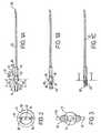
- FIGS. 6A to 6 Dshow various schematic side views of the locking mechanism of FIGS. 1A to 1 C when incorporated in a preferred butterfly catheter having a slightly shorter needle than the needle shown in FIGS. 1A to 1 C;
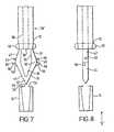
- FIG. 7is an enlarged side view of the retainer part and connector part shown in FIGS. 1 to 4 ;
- FIG. 8is a view corresponding to FIG. 7 , in the direction of the arrow marked 8 in FIG. 7 ;
- FIG. 9is a view corresponding to FIG. 8 , in the direction “ 9 ” in FIG. 8 but excluding the connector part 14 ;
- FIG. 10is an end view of an embodiment of a syringe assembly having an eccentrically located neck portion
- FIG. 11is a further embodiment of a hypodermic needle assembly, in which the section of a barrel of the assembly is non-circular;
- FIG. 12is a schematic side view of each of the assemblies shown in FIGS. 10 and 11 .
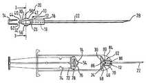
- FIGS. 1A to 1 C, FIG. 2 and FIG. 3A preferred locking mechanism 10 in accordance with a preferred embodiment of the present invention is shown in FIGS. 1A to 1 C, FIG. 2 and FIG. 3 .
- the locking mechanism 10comprises a retainer part 12 and a connector part 14 .
- the retainer part 12includes a body part 16 or a generally cylindrical needle retainer 16 having an elongate bore 18 formed therethrough.
- An adjacent end 20 of a hypodermic needle 22has a circular entrance aperture 24 thereto flush with one end 26 of the bore 18 .
- the other, distal end 28 of the needle 22is sharp, and it will be understood that the needle 22 has an internal bore (or lumen) (not shown) formed therealong for the transmission of material, such as medicine being injected to, or blood or other bodily fluids being extracted from a patient.
- the retainer part 12includes a pair of resilient legs 30 formed integrally with the cylindrical needle retainer 16 , the legs 30 being mutually joined at one end 32 thereof.
- the legs 32form a diamond-shaped section, consisting of V-shape end portion 31 adjacent an inwardly tapered portion 33 adjacent the needle retainer 16 .
- the joining of the legs in a “V”provides additional resilience against squashing thereof by the connector part 14 as will be described below.
- each leg 30includes a generally flat inner surface 34 , formed by two flat surfaces 36 , 38 and a generally concave or curved outer surface 40 , formed by two surfaces 42 , 44 .
- the arrangement of flat 34 , 36 , 38 surfaces and concave/curved 40 , 42 , 44 surfaces,provides additional resilience for the legs 30 against movement towards one another.
- FIGS. 7 to 9show enlarged views of the retainer 12 and connector 14 . It will be appreciated that the connector 14 is cylindrical and FIGS. 7 and 8 thus show a schematic section through this part.
- each leg 30includes a formation 46 formed thereon in the form of a lug 46 extending generally transverse to the longitudinal direction of the needle 22 .
- the retainer 12may include an annular seal 51 formed adjacent a rear end thereof (omitted for clarity in other drawings) for sealing inside the neck of the syringe.
- This sealis located well inside the neck portion as is the rear entrance to the needle and this means that almost no fluid is wasted as excess when injecting.
- the seal 51may be replaced with alternative sealing means in other embodiments
- the connector part 14 of the locking mechanismcomprises a cup-shaped element 48 having one end 50 which may be closed (or in other embodiments open) and a second end 52 which is open but includes an annular ledge 54 which is inwardly extending at an entrance to the cup.
- the legs 30in addition to the lugs 46 (which are symmetrically located about the longitudinal axis of the hypodermic needle), includes two further lugs 56 which are located somewhat asymmetrically about the axis of the needle 22 .
- the further lugs 56are spaced further along the legs 30 from the needle retainer part 16 of the retainer part 12 than the lugs 46 .
- the connector part 14may be moved linearly towards the retainer part 12 until the inner edge 58 of the ledge 54 engages the legs 30 as shown in FIG. 1 B. Further movement of the connector part 14 linearly in the axial longitudinal direction of the needle 22 causes the legs 30 to be transversely moved towards one another.
- the ledge 54rides over the further lugs 56 , the further lugs 56 having chamfered surfaces 58 allowing the ledge 54 to ride over the lugs 56 , but transverse flat surfaces 60 (perpendicular to the needle axis) opposing the chamfered surfaces 58 , the flat transverse surfaces 60 thus preventing removal of the connector part 14 from the retainer part 12 , once the ledge 54 has ridden over the lugs 56 to place the connector part 14 and retainer part 12 in the engaged configuration shown in FIG. 1 C.
- the preferred locking mechanism 10may be incorporated in a preferred syringe assembly 62 in accordance with a preferred embodiment of the present invention.
- the needle 22is a push-fit in the needle retainer 16 , the needle retainer including a series of circumferential ribs on the internal bore 18 thereof, e.g. about ten spaced circumferentially extending ribs, the ribs 18 compressing against the needle 22 in order to hold the needle 22 in position and provide a good seal. Accordingly, it is not necessary to use glue to attach the needle 22 .
- the syringe assembly 62includes a barrel 64 having a main cylindrical part 66 , a conical shoulder 68 and a cylindrical neck 72 .
- the assembly 62also has a plunger 72 having a stem 74 for operating a piston 76 , the piston 76 being sealed against the barrel main cylindrical part 66 with an O ring 78 .
- the neck 70 of the barrel 64includes at a rear end 80 thereof an internal annular recess or cavity 82 .
- the retainer part 12 holding the needle 22may be connected to a hub 84 (or the alternative hub 84 shown in FIG. 5 ) and, later, the retainer part 12 may be pushed into the neck 70 of the barrel 64 to the configuration shown in FIG.
- the lugs 46are resiliently engaged in the internal annular recess 82 at the rear end 80 of the neck 70 .
- the resilience of the lugs 46 and the legs 30is such that when the plunger 72 is drawn backwards to draw material such as a vaccine, medicine or bodily material such as blood into the barrel 64 , the retainer part 12 and hypodermic needle 22 are retained in position, with transverse surfaces 61 of lugs 46 engaging in the recess 82 .
- the hub 84is provided with a stop element/stop surface 86 for preventing forward movement of the needle 22 when the plunger 72 is pushed forwards. It will be appreciated that there is a gap 86 between the legs 30 such that fluid may flow from the barrel, through the gap 86 into the entrance aperture 24 and along the needle 22 or, of course, in the opposite direction.
- the plungerWhen the syringe assembly 62 is used to give an injection, the plunger is pushed forwards, for example, from the position shown in FIG. 4A to the position shown in FIG. 4 B and then to the position shown in FIG. 4 C. As the plunger 72 approaches the configuration shown in FIG. 4C , it will be appreciated that the locking mechanism 10 adopts first the configuration shown in FIG. 1A , then the configuration shown in FIG. 1 B and then the configuration shown in FIG. 1C which is the same as the configuration shown in FIG. 4 C.
- the connector part 14 of the locking mechanism 10moves along the legs 30 , it squashes the legs 30 towards one another and, in doing so, the lugs 46 disengage from the internal annular recess 82 in the neck portion 70 of the barrel 64 and, the ledge 54 of the connector part 14 rides over the lugs 56 . Accordingly, when the plunger 72 is pulled backwards to the position shown in FIG. 4B , the connector part 14 pulls the retainer part 12 and needle 22 with it. The needle 22 maintains a generally longitudinally configuration until the end 28 passes through the neck portion 70 and along the inside of the shoulder 68 of the barrel.
- the connector part 14provides a tilting force on the retainer part 12 and needle 22 , such that the needle tilts by about 5° as shown in FIG. 4 E and FIG. 4F , such that it is then not possible to push the needle forwards out through the neck 70 for reuse.
- the rear end 88 of the barrel 64includes a slight constriction 90 and the stem 74 includes a jamming element 92 shown for the purposes of clarity schematically only and only in FIG. 4F , which prevents the stem 74 from being fully removed from the barrel 64 .
- a weak spot 94 on the stem 74 of the plunger 72conveniently allows the plunger to be snapped for showing even the most inexperienced user or persistent attempted reuser of needles 22 that the needle 22 has been used and is now inoperative and should not be reused.
- FIGS. 6A to 6 Dshow a development on the apparatus shown in FIGS. 4 A to 4 F in which the preferred locking mechanism 10 of FIGS. 1A to 1 C, 2 and 3 is instead incorporated in a butterfly catheter 100 , this apparatus including a shorter needle 22 .
- the locking mechanism 10works on a similar principle in FIGS. 6A to 6 D and the connector part 14 has an open end 102 which may be connected to a fluid tube 104 for various purposes such as provision of a drip (not shown).
- the needle 22may be retracted into the butterfly device body 104 and a slightly shorter needle retainer 16 of the retainer part 12 and the retainer 16 shown in FIGS. 1 to 4 may be pulled longitudinally behind a tube section 106 of the body 104 such that the needle retainer 16 cannot be pushed inside the tube 106 again and the needle 22 therefore cannot be pushed forwards out of the body 104 for reuse.
- embodiments of the inventionmay provide a hypodermic medical device such as a syringe assembly in which a needle is secured, without glue or adhesive, in its optimal position for use in injecting or extracting.
- the needlemay be subsequently locked into the inner end of a plunger or piston to permit withdrawal wholly into the barrel of the syringe or the body of the device.
- the complete assemblymay then be discarded without fear of accidental infection through needlestick.
- the device/syringeis thus rendered safe and cannot be refilled or reused and it can be disposed of safely.
- the devicemay be produced in quantity at a competitive price.
- the retainer part 12which may also be considered a central hub combines a central channel for transmission of fluid being injected or extracted with a ribbed internal contour that engages with the surface of the needle.
- This internal locking mechanismshows that the needle is firmly secured in a base that is in turn married with forward end or neck of the syringe barrel.
- the outer surface of the central hub or retainer partis contoured such that the combined central hubs/retainer and needle assembly can be easily and firmly attached to the neck of the syringe barrel readying the syringe ready for use.
- the syringemay then be filled in the normal way for injection by drawing back the plunger, thus drawing injectable fluid into the barrel.
- the plungermay be depressed to a point short of where the lugs 56 engage with the connector part 12 , and the plunger may then be retracted as fluid is drawn in.
- the plungerWhen the fluid is transferred into a vial (not shown) or other receptacle (not shown) the plunger will be fully depressed such that it engages with the lugs. Accordingly, when the plunger is pulled back again, the needle is withdrawn into the barrel of the syringe and the unit can be discarded.
- the locking of the needleis secured by pulling the tail-end of the device until the needle disappears into the device.
- needlesmay be interchanged before use so that the clinician or other user can match a selection of needles with a selection of barrels.
- a standard barrelmay be capable of taking a range of needle sizes and profiles, while larger or smaller barrels may be supplied for applications falling outside the most commonly used sizes. Accordingly, the system is very flexible.
- the preferred embodiments of the present inventionare able to meet this requirement.
- blood collectionmay be used with embodiments of the invention, thus making “self-blunting” needles unnecessary.
- preferred embodiments of the inventionmay allow a plunger and safety needle to be fitted to a prefilled container, subject to dimensions, with a secure seal between the barrel and needle mounting. This is important since some prefilled syringes such as glass syringes for Meningitis immunisation do not always have in the prior art a needle which sits tightly in the neck of the barrel and fluid leaks out.
- devices such as hypodermic needles in accordance with preferred embodiments of the present inventionmay be simple to use compared to other safety syringes and may be priced at a level affordable to health services and workers in most countries since the cost may be similar to that of standard, i.e. basic reusable products.
- the connector part 14may be adapted such that in other embodiments, once the connector part is engaged with the retainer part, the full length of the legs 30 is located inside the connector part such that there is no passage for fluid past the connector part along the needle and the needle cannot therefore be used again to suck fluid into the barrel.
- Hubs 84 for needles of different sizesmay be colour-coded to provide helpful information.
- the syringe assembly 62is preferably rubber-free, including the O ring 78 .
- a push-on hub 84as shown in FIGS. 4A to 4 F for a syringe assembly 62 (it will be appreciated that the hub 84 snap-locks onto the front of the barrel in a conventional way)
- a half-turn/screw-lockmay be implemented for the engagement of the hub 84 with the barrel 64 , this generally being considered the American connection method, whereas the traditional conical snap connection system is used more in Europe.
- the barrel of the syringe assembly 62may be made from various materials including medical grade polypropylene. Alternatively, a clear polycarbonate may be used. Other materials may be used.
- the medical device/syringe assemblymay be sterilised, for example, using ethylene oxide or gamma rays or an electron beam method.
- the plungermay be made from various materials including polyurethane or other suitable materials and the plunger may be coloured, for example red or yellow or other suitable colours.
- the retainer part and connector part of the locking mechanismare preferably formed in plastics material and the needle is most preferably steel, being rolled, welded, cut and polished in a conventional way.
- FIG. 10shows a modification of the assembly shown in FIG. 4 .
- the syringe barrel 100 in this embodimenthas an eccentrically located forward neck portion 102 , as shown in FIG. 10 , which also shows finger tabs 104 of the assembly.
- the needle 106is retained by a retainer 12 the same as that shown in FIGS. 8 to 10 and the plunger 108 has a connector part 104 located in an eccentric position corresponding to the position of the neck 102 and needle 106 , the connector part 14 being as shown and described with reference to the embodiments of FIGS. 1 to 4 and 7 to 9 .
- the assembly in FIGS. 10 and 12includes an eccentrically domed hub 110 .
- the plunger 108has a stem 112 with an X-shaped section.
- FIG. 11shows an alternative embodiment similar to the embodiment of FIG. 10 , but the barrel 100 of the syringe assembly has a non-circular section, namely an elliptical section. In this embodiment, the groove and plates 116 , 118 may be omitted. It will be appreciated that the side view of the FIG. 11 embodiment is shown in FIG. 12 , as is the side view of the FIG. 10 embodiment.
- the needle 106is retained in place by lugs 46 on an internal recess of the syringe, and, once fully depressed, the connector part 14 on the plunger 108 engages with the retainer part 12 , and the needle 106 is then retracted inside the syringe assembly, on retraction of the plunger 108 .
- a medical devicesuch as a syringe assembly having an eccentric neck portion may be desirable in cases in which the cross-dimension or diameter of the assembly is relatively large.
- the eccentric location of the neck portionmay enable a user of the assembly to place the assembly relatively close to or relatively parallel to a body surface of a patient, for example, for inserting a needle at a shallow angle into a patient.
- an important advantageis that the retainer 12 and needle 22 may be compatible with various syringe plunger devices or other devices and/or that the neck of the syringe may be connected to various types of device such as a needle with hub or a tube for pushing or sucking fluid along the tube.
- one type of locking mechanism/needlemay be applicable to various devices, thus reducing costs.
- the same locking mechanism, i.e. retainer part 12 and connector part 14may be used in 1, 5, 10, 20 ml or other sizes of hypodermic syringe assembly.
- a standard hub like the hub 84 ′may be employed.
- Devices in accordance with the inventionmay have application in either human medical or veterinary fields and may even have application outside medical fields.
Landscapes
- Health & Medical Sciences (AREA)
- Life Sciences & Earth Sciences (AREA)
- Engineering & Computer Science (AREA)
- Animal Behavior & Ethology (AREA)
- Public Health (AREA)
- Heart & Thoracic Surgery (AREA)
- Hematology (AREA)
- Anesthesiology (AREA)
- Veterinary Medicine (AREA)
- General Health & Medical Sciences (AREA)
- Biomedical Technology (AREA)
- Vascular Medicine (AREA)
- Biophysics (AREA)
- Pulmonology (AREA)
- Environmental & Geological Engineering (AREA)
- Infusion, Injection, And Reservoir Apparatuses (AREA)
- Surgical Instruments (AREA)
- External Artificial Organs (AREA)
- Medicines That Contain Protein Lipid Enzymes And Other Medicines (AREA)
Abstract
Description
Claims (60)
Applications Claiming Priority (3)
| Application Number | Priority Date | Filing Date | Title |
|---|---|---|---|
| GR20000100459 | 2000-12-22 | ||
| GR20000100459 | 2000-12-22 | ||
| PCT/EP2001/000817WO2002026295A2 (en) | 2000-12-22 | 2001-01-25 | Medical device and locking mechanism therefor |
Publications (2)
| Publication Number | Publication Date |
|---|---|
| US20020173751A1 US20020173751A1 (en) | 2002-11-21 |
| US6913595B2true US6913595B2 (en) | 2005-07-05 |
Family
ID=38057220
Family Applications (1)
| Application Number | Title | Priority Date | Filing Date |
|---|---|---|---|
| US10/069,688Expired - LifetimeUS6913595B2 (en) | 2000-12-22 | 2001-01-25 | Medical device and locking mechanism therefor |
Country Status (20)
| Country | Link |
|---|---|
| US (1) | US6913595B2 (en) |
| EP (1) | EP1244484B1 (en) |
| JP (1) | JP2004520091A (en) |
| KR (1) | KR20040016830A (en) |
| CN (1) | CN1267163C (en) |
| AT (1) | ATE254940T1 (en) |
| AU (2) | AU2001228494B2 (en) |
| BR (1) | BR0116394A (en) |
| CA (1) | CA2432547A1 (en) |
| DE (1) | DE60101307T2 (en) |
| DK (1) | DK1244484T3 (en) |
| ES (1) | ES2212791T3 (en) |
| HK (1) | HK1051654B (en) |
| IL (2) | IL156347A0 (en) |
| MX (1) | MXPA03005518A (en) |
| PT (1) | PT1244484E (en) |
| RU (1) | RU2271835C2 (en) |
| TR (1) | TR200302227T4 (en) |
| WO (1) | WO2002026295A2 (en) |
| ZA (1) | ZA200304559B (en) |
Cited By (37)
| Publication number | Priority date | Publication date | Assignee | Title |
|---|---|---|---|---|
| US20060178624A1 (en)* | 2004-07-02 | 2006-08-10 | Chao-Song Hsue | Retractable safety syringe with push rod in plunger |
| US20090036861A1 (en)* | 2007-08-01 | 2009-02-05 | Hospira, Inc. | Medicament admixing system |
| US20120010567A1 (en)* | 2006-08-14 | 2012-01-12 | Global Medisafe Holdings Ltd | Single use self-disabling syringe |
| US8486024B2 (en) | 2011-04-27 | 2013-07-16 | Covidien Lp | Safety IV catheter assemblies |
| US8628497B2 (en) | 2011-09-26 | 2014-01-14 | Covidien Lp | Safety catheter |
| US8715250B2 (en) | 2011-09-26 | 2014-05-06 | Covidien Lp | Safety catheter and needle assembly |
| US8721612B2 (en) | 2010-12-17 | 2014-05-13 | Hospira, Inc. | System and method for intermixing the contents of two containers |
| US8834444B2 (en) | 2011-10-03 | 2014-09-16 | Hospira, Inc. | System and method for mixing the contents of two containers |
| US8834422B2 (en) | 2011-10-14 | 2014-09-16 | Covidien Lp | Vascular access assembly and safety device |
| US8939938B2 (en) | 2006-10-12 | 2015-01-27 | Covidien Lp | Needle tip protector |
| WO2016037127A1 (en)* | 2014-09-05 | 2016-03-10 | C.R. Bard, Inc. | Catheter insertion device including retractable needle |
| US9522254B2 (en) | 2013-01-30 | 2016-12-20 | Vascular Pathways, Inc. | Systems and methods for venipuncture and catheter placement |
| US9616201B2 (en) | 2011-01-31 | 2017-04-11 | Vascular Pathways, Inc. | Intravenous catheter and insertion device with reduced blood spatter |
| US9675784B2 (en) | 2007-04-18 | 2017-06-13 | Vascular Pathways, Inc. | Intravenous catheter insertion and blood sample devices and method of use |
| US9861792B2 (en) | 2011-02-25 | 2018-01-09 | C. R. Bard, Inc. | Medical component insertion device including a retractable needle |
| US9872971B2 (en) | 2010-05-14 | 2018-01-23 | C. R. Bard, Inc. | Guidewire extension system for a catheter placement device |
| US9950139B2 (en) | 2010-05-14 | 2018-04-24 | C. R. Bard, Inc. | Catheter placement device including guidewire and catheter control elements |
| US10220191B2 (en) | 2005-07-06 | 2019-03-05 | Vascular Pathways, Inc. | Intravenous catheter insertion device and method of use |
| US10335556B2 (en) | 2013-12-06 | 2019-07-02 | Genentech, Inc. | Apparatus and methods for low-volume medicament delivery |
| US10384039B2 (en) | 2010-05-14 | 2019-08-20 | C. R. Bard, Inc. | Catheter insertion device including top-mounted advancement components |
| US10426931B2 (en) | 2010-05-14 | 2019-10-01 | C. R. Bard, Inc. | Catheter placement device and method |
| US10493262B2 (en) | 2016-09-12 | 2019-12-03 | C. R. Bard, Inc. | Blood control for a catheter insertion device |
| US10674950B2 (en) | 2011-04-26 | 2020-06-09 | Velano Vascular, Inc. | Systems and methods for phlebotomy through a peripheral IV catheter |
| US10773056B2 (en) | 2017-03-21 | 2020-09-15 | Velano Vascular, Inc. | Systems and methods for controlling catheter device size |
| USD903101S1 (en) | 2011-05-13 | 2020-11-24 | C. R. Bard, Inc. | Catheter |
| USD903100S1 (en) | 2015-05-01 | 2020-11-24 | C. R. Bard, Inc. | Catheter placement device |
| USD921884S1 (en) | 2018-07-27 | 2021-06-08 | Bard Access Systems, Inc. | Catheter insertion device |
| US11040176B2 (en) | 2015-05-15 | 2021-06-22 | C. R. Bard, Inc. | Catheter placement device including an extensible needle safety component |
| US11090461B2 (en) | 2017-03-21 | 2021-08-17 | Velano Vascular, Inc. | Devices and methods for fluid transfer through a placed peripheral intravenous catheter |
| US11207498B2 (en) | 2019-08-20 | 2021-12-28 | Velano Vascular, Inc. | Fluid transfer devices with extended length catheters and methods of using the same |
| US11331023B2 (en) | 2011-04-26 | 2022-05-17 | Velano Vascular, Inc. | Systems and methods for phlebotomy through a peripheral IV catheter |
| US11389626B2 (en) | 2018-03-07 | 2022-07-19 | Bard Access Systems, Inc. | Guidewire advancement and blood flashback systems for a medical device insertion system |
| US11389624B2 (en) | 2020-11-26 | 2022-07-19 | Avia Vascular, Llc | Blood collection devices, systems, and methods |
| US11400260B2 (en) | 2017-03-01 | 2022-08-02 | C. R. Bard, Inc. | Catheter insertion device |
| US11559665B2 (en) | 2019-08-19 | 2023-01-24 | Becton, Dickinson And Company | Midline catheter placement device |
| US11925779B2 (en) | 2010-05-14 | 2024-03-12 | C. R. Bard, Inc. | Catheter insertion device including top-mounted advancement components |
| US12440652B2 (en) | 2019-09-20 | 2025-10-14 | Bard Peripheral Vascular, Inc. | Intravenous catheter-placement device and method thereof |
Families Citing this family (19)
| Publication number | Priority date | Publication date | Assignee | Title |
|---|---|---|---|---|
| CA2324045A1 (en) | 2000-10-20 | 2002-04-20 | Universite De Sherbrooke | No-needle syringe for the subcutaneous injection of medicated powders |
| GR20020100365A (en) | 2002-08-06 | 2004-04-22 | Nicodel S.A. | Medical device |
| NL1021689C2 (en)* | 2002-10-18 | 2004-05-12 | Advanced Protective Injection | Injection syringe for delivering medication on patient comprises liquid container, needle with needle mount, and blocker |
| WO2005023344A1 (en)* | 2003-09-05 | 2005-03-17 | Medical Patents Ltd. | Injection syringe with retractable needle |
| NL1024230C2 (en)* | 2003-09-05 | 2005-03-08 | Medical Patents Ltd | New injection syringe comprises a liquid container with an annular outer edge, a piston having a piston head, a needle with a needle mount, and blocking mechanisms |
| CN100400119C (en)* | 2003-10-15 | 2008-07-09 | 开曼群岛商顶尖堂控股股份有限公司 | Needle Retractable Safety Syringes |
| DE10348603A1 (en)* | 2003-10-20 | 2005-05-19 | Klinika Medical Gmbh | Cannula holder comprises an unlocking mechanism which is constituted so that after its operation the cannula and/or the adapter will fall into the cannula container |
| CN100420491C (en)* | 2004-06-15 | 2008-09-24 | 精碟科技股份有限公司 | Safety syringe |
| DE202004011516U1 (en)* | 2004-07-22 | 2005-12-08 | Schwarzbich, Jörg | syringe |
| US20060264824A1 (en)* | 2005-05-20 | 2006-11-23 | Swisher Kyle Y Iii | Disposable safety medical syringe assembly and method of manufacture |
| US8398397B2 (en)* | 2008-03-12 | 2013-03-19 | Ultradent Products, Inc. | Dental intraligamentary injection needles and related methods of manufacture |
| EP2123317A1 (en)* | 2008-05-20 | 2009-11-25 | Sanofi-Aventis Deutschland GmbH | Drive assembly suitable for use in drug delivery device and drug delivery device |
| NL2001702C2 (en)* | 2008-06-19 | 2009-12-22 | Addino B V | Injection syringe with possibility of needle storage. |
| US9186100B2 (en) | 2011-04-26 | 2015-11-17 | Velano Vascular, Inc. | Systems and methods for phlebotomy through a peripheral IV catheter |
| CN110974255B (en)* | 2014-08-26 | 2022-10-11 | 威蓝诺血管股份有限公司 | System and method for drawing blood through a peripheral IV catheter |
| FR3053254A1 (en) | 2016-06-29 | 2018-01-05 | Nicodel S.A. | INJECTION SYRINGE |
| FR3053255A1 (en) | 2016-06-29 | 2018-01-05 | Nicodel S.A. | INJECTION DEVICE |
| KR101985072B1 (en)* | 2017-03-29 | 2019-05-31 | 최근욱 | Medicine injection niddle unit having stick injury and infection preventing fuction |
| WO2020237420A1 (en)* | 2019-05-24 | 2020-12-03 | Becton, Dickinson And Company | Needle-tract assistant including components and methods thereof |
Citations (51)
| Publication number | Priority date | Publication date | Assignee | Title |
|---|---|---|---|---|
| US4675005A (en) | 1986-05-08 | 1987-06-23 | Deluccia James | Retractable disposable syringe |
| US4747830A (en) | 1986-04-28 | 1988-05-31 | Gloyer Walter W | Anti-stick contagion free disposable hypodermic safety syringe |
| EP0321903A2 (en) | 1987-12-21 | 1989-06-28 | Stuart M. Dolgin | Fluid passing apparatus with means for covering the same |
| US4904242A (en) | 1987-04-29 | 1990-02-27 | Kulli John C | Phlebotomy set with safety retracting needle |
| WO1990007948A1 (en) | 1989-01-19 | 1990-07-26 | Jaime Caralt Batlle | Single use hypodermic syringe |
| US4950241A (en) | 1988-12-27 | 1990-08-21 | Sherwood Medical Company | Disposable syringe |
| WO1991008788A1 (en) | 1989-12-20 | 1991-06-27 | Lucio Rossi | Single-use safety syringe provided with retractile needle and device preventing it from being reused |
| WO1991012842A1 (en) | 1990-03-01 | 1991-09-05 | Advanced Protective Injection Systems B.V. | Protection assembly for an injection syringe |
| US5047016A (en) | 1987-12-21 | 1991-09-10 | Stuart M. Dolgin | Fluid passing apparatus with means for covering the same |
| EP0467173A1 (en) | 1990-07-19 | 1992-01-22 | Nardino Righi | Disposable safety syringe |
| US5084029A (en) | 1988-12-07 | 1992-01-28 | Nacci Carla | Syringe which automatically make the hypodermic needle harmless after use |
| WO1992011883A1 (en) | 1990-12-28 | 1992-07-23 | Yulami Pty Ltd | Syringe device |
| US5201718A (en) | 1987-04-22 | 1993-04-13 | Whisson Maxwell E | Parenteral device |
| US5342309A (en)* | 1993-03-05 | 1994-08-30 | Becton, Dickinson And Company | Syringe having safety shield |
| US5344403A (en) | 1993-06-09 | 1994-09-06 | Rahnfong Lee | Simple retractable safety syringe |
| US5378240A (en) | 1989-11-08 | 1995-01-03 | Curie; Napoleon | Syringe with retractable needle mount |
| US5395346A (en) | 1993-07-26 | 1995-03-07 | Maggioni; Tarcisio | Disposable syringe with a retractable needle |
| US5399170A (en) | 1989-05-04 | 1995-03-21 | Western Medical Products Pty Limited | Syringe |
| US5405326A (en) | 1993-08-26 | 1995-04-11 | Habley Medical Technology Corporation | Disposable safety syringe with retractable shuttle for luer lock needle |
| US5415646A (en) | 1994-05-11 | 1995-05-16 | Roth; Noah M. | One use safety locking syringe |
| US5415648A (en) | 1993-07-08 | 1995-05-16 | Malay; Manuel R. | Multiple purpose syringe |
| US5415638A (en) | 1988-12-14 | 1995-05-16 | Inviro Medical Devices, Ltd. | Safety syringe needle device with interchangeable and retractable needle platform |
| US5417661A (en) | 1994-05-04 | 1995-05-23 | Stringer; Jeffrey L. | Safety syringe |
| US5431631A (en) | 1994-10-21 | 1995-07-11 | Lu; Wen-Chin | Safety syringe with externally connectable and internally retractable self-biased needle |
| FR2718358A1 (en) | 1994-04-11 | 1995-10-13 | Elfandi Patrice | Single use syringe with retractable needle. |
| US5462531A (en) | 1988-12-14 | 1995-10-31 | Inviro Medical Devices Ltd. | Safety syringe needle device with interchangeable and retractable needle platform |
| US5496278A (en) | 1994-07-25 | 1996-03-05 | Buff; Danny | Safety syringe with self-sealing needle retraction and retracted member lock |
| US5514100A (en) | 1993-08-23 | 1996-05-07 | Mahurkar; Sakharam D. | Hypodermic needle assembly |
| US5531705A (en) | 1990-11-30 | 1996-07-02 | Nujenko Pty Ltd | Syringe unit |
| US5538507A (en) | 1990-09-27 | 1996-07-23 | De Kler; Dirk | Hypodermic syringe |
| US5569203A (en) | 1995-06-23 | 1996-10-29 | Chen; Long-Hsiung | Simplified safety syringe with retractable self-biased needle and minimized plunger |
| US5584817A (en) | 1994-07-15 | 1996-12-17 | A.P.I.S. Medical B.V. | Prefilled injection syringe assembly |
| US5593387A (en) | 1994-03-02 | 1997-01-14 | Rupp; Roberta N. | Non-reusable syringe |
| US5613952A (en) | 1991-12-23 | 1997-03-25 | Syringe Develpoment Partners | Safety syringe |
| GB2306332A (en) | 1995-10-28 | 1997-05-07 | Fenson & Company Ltd | A hypodermic syringe |
| GB2315022A (en) | 1995-04-20 | 1998-01-21 | Napoleon Curie | A single use syringe |
| US5720727A (en) | 1994-09-06 | 1998-02-24 | Medisys Technologies, Inc. | Safety syringe |
| US5762633A (en) | 1993-10-26 | 1998-06-09 | Eastland Technology Australia Pty, Ltd. | Syringe or like parenteral device |
| US5785687A (en) | 1996-03-13 | 1998-07-28 | Saito; Yoshikuni | Syringe assembly |
| US5788672A (en) | 1993-06-29 | 1998-08-04 | Saito; Yoshikuni | Hub for syringe, connecting structure of hub, syringe, piston, needle assembly unit, connecting structure between needle assembly unit and syringe, syringe assembly and method of assembling syringe assembly |
| US5792107A (en) | 1909-05-10 | 1998-08-11 | Petrocelli; Pasqualino | Disposable safety syringe |
| EP0602882B1 (en) | 1992-12-14 | 1999-03-24 | Becton, Dickinson and Company | Safety needle syringe |
| US5891092A (en) | 1997-10-02 | 1999-04-06 | Visionary Medical Products Corporation | Disposable safety syringe and method of making the same |
| US5931813A (en) | 1997-12-26 | 1999-08-03 | Liu; Wen-Neng | Retractable and destructible safety syringe |
| US5938641A (en) | 1998-01-07 | 1999-08-17 | Villanueva; George | Safety syringe |
| US5968020A (en) | 1993-03-12 | 1999-10-19 | Saito; Yoshikuni | Syringe assembly |
| US5976108A (en) | 1998-06-03 | 1999-11-02 | Liu; Wen-Neng | Safety vein syringe with retractable standard needle |
| WO1999062579A1 (en) | 1998-05-30 | 1999-12-09 | Nmt Group Plc | Hypodermic needle |
| GB2342047A (en) | 1998-09-25 | 2000-04-05 | Charles Mcnairn | Single use syringe |
| US6210371B1 (en)* | 1999-03-30 | 2001-04-03 | Retractable Technologies, Inc. | Winged I.V. set |
| US20010021821A1 (en) | 2000-02-24 | 2001-09-13 | Xiping Wang | Safety syringe |
Family Cites Families (8)
| Publication number | Priority date | Publication date | Assignee | Title |
|---|---|---|---|---|
| KR930003314B1 (en)* | 1984-11-21 | 1993-04-26 | 에발트 픽크하르트 | syringe |
| DE68906541T2 (en)* | 1988-12-07 | 1993-11-04 | Carla Nacci | SYRINGE WITH HYPODERMIC NEEDLE, AUTOMATICALLY SAFE TO USE. |
| JP3114203B2 (en)* | 1989-11-08 | 2000-12-04 | キュリー,ナポレオン | Syringe with retractable needle mount |
| JPH06508770A (en)* | 1991-04-17 | 1994-10-06 | ライルズ,ルイス | Syringe |
| US5584814A (en)* | 1995-01-26 | 1996-12-17 | Schuster; John H. | Syringe actuation system |
| JP3399223B2 (en)* | 1996-04-24 | 2003-04-21 | 富士ゼロックス株式会社 | Wire harness fixing device |
| JP3764786B2 (en)* | 1996-10-30 | 2006-04-12 | 株式会社セベル・ピコ | Fasteners for jewelry |
| JP2000316613A (en)* | 1999-05-11 | 2000-11-21 | Ykk Corp | Male and female locking device with tape |
- 2001
- 2001-01-25RURU2003123096/14Apatent/RU2271835C2/ennot_activeIP Right Cessation
- 2001-01-25KRKR10-2003-7008457Apatent/KR20040016830A/ennot_activeAbandoned
- 2001-01-25DKDK01984289Tpatent/DK1244484T3/enactive
- 2001-01-25CACA002432547Apatent/CA2432547A1/ennot_activeAbandoned
- 2001-01-25BRBR0116394-9Apatent/BR0116394A/enactiveSearch and Examination
- 2001-01-25DEDE60101307Tpatent/DE60101307T2/ennot_activeExpired - Fee Related
- 2001-01-25WOPCT/EP2001/000817patent/WO2002026295A2/enactiveIP Right Grant
- 2001-01-25CNCNB018053319Apatent/CN1267163C/ennot_activeExpired - Fee Related
- 2001-01-25ILIL15634701Apatent/IL156347A0/enunknown
- 2001-01-25AUAU2001228494Apatent/AU2001228494B2/ennot_activeCeased
- 2001-01-25TRTR2003/02227Tpatent/TR200302227T4/enunknown
- 2001-01-25EPEP01984289Apatent/EP1244484B1/ennot_activeExpired - Lifetime
- 2001-01-25ESES01984289Tpatent/ES2212791T3/ennot_activeExpired - Lifetime
- 2001-01-25JPJP2002530124Apatent/JP2004520091A/enactivePending
- 2001-01-25AUAU2849401Apatent/AU2849401A/enactivePending
- 2001-01-25USUS10/069,688patent/US6913595B2/ennot_activeExpired - Lifetime
- 2001-01-25PTPT01984289Tpatent/PT1244484E/enunknown
- 2001-01-25HKHK03102269.7Apatent/HK1051654B/ennot_activeIP Right Cessation
- 2001-01-25ATAT01984289Tpatent/ATE254940T1/ennot_activeIP Right Cessation
- 2001-01-25MXMXPA03005518Apatent/MXPA03005518A/enactiveIP Right Grant
- 2003
- 2003-06-08ILIL156347Apatent/IL156347A/ennot_activeIP Right Cessation
- 2003-06-11ZAZA200304559Apatent/ZA200304559B/enunknown
Patent Citations (61)
| Publication number | Priority date | Publication date | Assignee | Title |
|---|---|---|---|---|
| US5792107A (en) | 1909-05-10 | 1998-08-11 | Petrocelli; Pasqualino | Disposable safety syringe |
| US4747830A (en) | 1986-04-28 | 1988-05-31 | Gloyer Walter W | Anti-stick contagion free disposable hypodermic safety syringe |
| US4675005A (en) | 1986-05-08 | 1987-06-23 | Deluccia James | Retractable disposable syringe |
| US5201718A (en) | 1987-04-22 | 1993-04-13 | Whisson Maxwell E | Parenteral device |
| US4904242A (en) | 1987-04-29 | 1990-02-27 | Kulli John C | Phlebotomy set with safety retracting needle |
| EP0321903A2 (en) | 1987-12-21 | 1989-06-28 | Stuart M. Dolgin | Fluid passing apparatus with means for covering the same |
| US5047016A (en) | 1987-12-21 | 1991-09-10 | Stuart M. Dolgin | Fluid passing apparatus with means for covering the same |
| US5084029A (en) | 1988-12-07 | 1992-01-28 | Nacci Carla | Syringe which automatically make the hypodermic needle harmless after use |
| US5415638A (en) | 1988-12-14 | 1995-05-16 | Inviro Medical Devices, Ltd. | Safety syringe needle device with interchangeable and retractable needle platform |
| US5688240A (en) | 1988-12-14 | 1997-11-18 | Inviro Medical Devices Ltd. | Safety syringe needle device with interchangeable and retractable needle platform |
| US5462531A (en) | 1988-12-14 | 1995-10-31 | Inviro Medical Devices Ltd. | Safety syringe needle device with interchangeable and retractable needle platform |
| US4950241A (en) | 1988-12-27 | 1990-08-21 | Sherwood Medical Company | Disposable syringe |
| WO1990007948A1 (en) | 1989-01-19 | 1990-07-26 | Jaime Caralt Batlle | Single use hypodermic syringe |
| US5399170A (en) | 1989-05-04 | 1995-03-21 | Western Medical Products Pty Limited | Syringe |
| EP0500613B1 (en) | 1989-11-08 | 1995-08-30 | CURIE, Napoleon | Syringe with retractable needle mount |
| US5378240A (en) | 1989-11-08 | 1995-01-03 | Curie; Napoleon | Syringe with retractable needle mount |
| WO1991008788A1 (en) | 1989-12-20 | 1991-06-27 | Lucio Rossi | Single-use safety syringe provided with retractile needle and device preventing it from being reused |
| US5364359A (en) | 1990-03-01 | 1994-11-15 | Advanced Protective Injection Systems Medical B.V. | Syringe with retractable needle |
| WO1991012842A1 (en) | 1990-03-01 | 1991-09-05 | Advanced Protective Injection Systems B.V. | Protection assembly for an injection syringe |
| US5163918A (en) | 1990-07-19 | 1992-11-17 | Nardino Righi | Disposable safety syringe |
| EP0467173A1 (en) | 1990-07-19 | 1992-01-22 | Nardino Righi | Disposable safety syringe |
| US5538507A (en) | 1990-09-27 | 1996-07-23 | De Kler; Dirk | Hypodermic syringe |
| US5531705A (en) | 1990-11-30 | 1996-07-02 | Nujenko Pty Ltd | Syringe unit |
| WO1992011883A1 (en) | 1990-12-28 | 1992-07-23 | Yulami Pty Ltd | Syringe device |
| US5613952A (en) | 1991-12-23 | 1997-03-25 | Syringe Develpoment Partners | Safety syringe |
| EP0602882B1 (en) | 1992-12-14 | 1999-03-24 | Becton, Dickinson and Company | Safety needle syringe |
| US5342309A (en)* | 1993-03-05 | 1994-08-30 | Becton, Dickinson And Company | Syringe having safety shield |
| US5968020A (en) | 1993-03-12 | 1999-10-19 | Saito; Yoshikuni | Syringe assembly |
| US5344403A (en) | 1993-06-09 | 1994-09-06 | Rahnfong Lee | Simple retractable safety syringe |
| US5879339A (en) | 1993-06-29 | 1999-03-09 | Saito; Yoshikuni | Hub for syringe, connecting structure of hub, syringe, piston, needle assembly unit, connecting structure between needle assembly unit and syringe, syringe assembly and method of assembling syringe assembly |
| US5788672A (en) | 1993-06-29 | 1998-08-04 | Saito; Yoshikuni | Hub for syringe, connecting structure of hub, syringe, piston, needle assembly unit, connecting structure between needle assembly unit and syringe, syringe assembly and method of assembling syringe assembly |
| US5415648A (en) | 1993-07-08 | 1995-05-16 | Malay; Manuel R. | Multiple purpose syringe |
| US5395346A (en) | 1993-07-26 | 1995-03-07 | Maggioni; Tarcisio | Disposable syringe with a retractable needle |
| EP0636381B1 (en) | 1993-07-26 | 1997-08-13 | Finestyle Properties Limited | Disposable syringe with a retractable needle |
| US5514100A (en) | 1993-08-23 | 1996-05-07 | Mahurkar; Sakharam D. | Hypodermic needle assembly |
| US5891105A (en) | 1993-08-23 | 1999-04-06 | Mahurkar; Sakharam D. | Hypodermic needle assembly |
| US5685862A (en) | 1993-08-23 | 1997-11-11 | Mahurkar; Sakharam D. | Hypodermic needle assembly |
| US5405326A (en) | 1993-08-26 | 1995-04-11 | Habley Medical Technology Corporation | Disposable safety syringe with retractable shuttle for luer lock needle |
| US5762633A (en) | 1993-10-26 | 1998-06-09 | Eastland Technology Australia Pty, Ltd. | Syringe or like parenteral device |
| US5593387A (en) | 1994-03-02 | 1997-01-14 | Rupp; Roberta N. | Non-reusable syringe |
| FR2718358A1 (en) | 1994-04-11 | 1995-10-13 | Elfandi Patrice | Single use syringe with retractable needle. |
| US5417661A (en) | 1994-05-04 | 1995-05-23 | Stringer; Jeffrey L. | Safety syringe |
| US5415646A (en) | 1994-05-11 | 1995-05-16 | Roth; Noah M. | One use safety locking syringe |
| US5584817A (en) | 1994-07-15 | 1996-12-17 | A.P.I.S. Medical B.V. | Prefilled injection syringe assembly |
| US5667494A (en) | 1994-07-15 | 1997-09-16 | A.P.I.S. Medical B.V. | Prefilled injection syringe assembly |
| US5496278A (en) | 1994-07-25 | 1996-03-05 | Buff; Danny | Safety syringe with self-sealing needle retraction and retracted member lock |
| US5720727A (en) | 1994-09-06 | 1998-02-24 | Medisys Technologies, Inc. | Safety syringe |
| US5431631A (en) | 1994-10-21 | 1995-07-11 | Lu; Wen-Chin | Safety syringe with externally connectable and internally retractable self-biased needle |
| GB2315022A (en) | 1995-04-20 | 1998-01-21 | Napoleon Curie | A single use syringe |
| US5997511A (en) | 1995-04-20 | 1999-12-07 | Curie; Napoleon | Single use syringe |
| US5569203A (en) | 1995-06-23 | 1996-10-29 | Chen; Long-Hsiung | Simplified safety syringe with retractable self-biased needle and minimized plunger |
| GB2306332A (en) | 1995-10-28 | 1997-05-07 | Fenson & Company Ltd | A hypodermic syringe |
| US5785687A (en) | 1996-03-13 | 1998-07-28 | Saito; Yoshikuni | Syringe assembly |
| US5891092A (en) | 1997-10-02 | 1999-04-06 | Visionary Medical Products Corporation | Disposable safety syringe and method of making the same |
| US5931813A (en) | 1997-12-26 | 1999-08-03 | Liu; Wen-Neng | Retractable and destructible safety syringe |
| US5938641A (en) | 1998-01-07 | 1999-08-17 | Villanueva; George | Safety syringe |
| WO1999062579A1 (en) | 1998-05-30 | 1999-12-09 | Nmt Group Plc | Hypodermic needle |
| US5976108A (en) | 1998-06-03 | 1999-11-02 | Liu; Wen-Neng | Safety vein syringe with retractable standard needle |
| GB2342047A (en) | 1998-09-25 | 2000-04-05 | Charles Mcnairn | Single use syringe |
| US6210371B1 (en)* | 1999-03-30 | 2001-04-03 | Retractable Technologies, Inc. | Winged I.V. set |
| US20010021821A1 (en) | 2000-02-24 | 2001-09-13 | Xiping Wang | Safety syringe |
Cited By (91)
| Publication number | Priority date | Publication date | Assignee | Title |
|---|---|---|---|---|
| US20060178624A1 (en)* | 2004-07-02 | 2006-08-10 | Chao-Song Hsue | Retractable safety syringe with push rod in plunger |
| US10912930B2 (en) | 2005-07-06 | 2021-02-09 | Vascular Pathways, Inc. | Intravenous catheter insertion device and method of use |
| US11577054B2 (en) | 2005-07-06 | 2023-02-14 | Vascular Pathways, Inc. | Intravenous catheter insertion device and method of use |
| US12370349B2 (en) | 2005-07-06 | 2025-07-29 | Vascular Pathways, Inc. | Intravenous catheter insertion device and method of use |
| US11020571B2 (en) | 2005-07-06 | 2021-06-01 | Vascular Pathways, Inc. | Intravenous catheter insertion device and method of use |
| US10806906B2 (en) | 2005-07-06 | 2020-10-20 | Vascular Pathways, Inc. | Intravenous catheter insertion device and method of use |
| US10220191B2 (en) | 2005-07-06 | 2019-03-05 | Vascular Pathways, Inc. | Intravenous catheter insertion device and method of use |
| US11925778B2 (en) | 2005-07-06 | 2024-03-12 | Vascular Pathways, Inc. | Intravenous catheter insertion device |
| US20120010567A1 (en)* | 2006-08-14 | 2012-01-12 | Global Medisafe Holdings Ltd | Single use self-disabling syringe |
| US8939938B2 (en) | 2006-10-12 | 2015-01-27 | Covidien Lp | Needle tip protector |
| US9675784B2 (en) | 2007-04-18 | 2017-06-13 | Vascular Pathways, Inc. | Intravenous catheter insertion and blood sample devices and method of use |
| US9757540B2 (en) | 2007-04-18 | 2017-09-12 | Vascular Pathways, Inc. | Intravenous catheter insertion and blood sample devices and method of use |
| US10086171B2 (en) | 2007-05-07 | 2018-10-02 | Vascular Pathways, Inc. | Intravenous catheter insertion and blood sample devices and method of use |
| US10799680B2 (en) | 2007-05-07 | 2020-10-13 | Vascular Pathways, Inc. | Intravenous catheter insertion and blood sample devices and method of use |
| US10525236B2 (en) | 2007-05-07 | 2020-01-07 | Vascular Pathways, Inc. | Intravenous catheter insertion and blood sample devices and method of use |
| US9205026B2 (en) | 2007-08-01 | 2015-12-08 | Hospira, Inc. | Medicament admixing system |
| US8801689B2 (en) | 2007-08-01 | 2014-08-12 | Hospira, Inc. | Medicament admixing system |
| US20090036861A1 (en)* | 2007-08-01 | 2009-02-05 | Hospira, Inc. | Medicament admixing system |
| US9205025B2 (en) | 2007-08-01 | 2015-12-08 | Hospira, Inc. | Medicament admixing system |
| US9198832B2 (en) | 2007-08-01 | 2015-12-01 | Hospira, Inc. | Medicament admixing system |
| US10384039B2 (en) | 2010-05-14 | 2019-08-20 | C. R. Bard, Inc. | Catheter insertion device including top-mounted advancement components |
| US10688281B2 (en) | 2010-05-14 | 2020-06-23 | C. R. Bard, Inc. | Catheter placement device including guidewire and catheter control elements |
| US11000678B2 (en) | 2010-05-14 | 2021-05-11 | C. R. Bard, Inc. | Catheter placement device and method |
| US11278702B2 (en) | 2010-05-14 | 2022-03-22 | C. R. Bard, Inc. | Guidewire extension system for a catheter placement device |
| US10426931B2 (en) | 2010-05-14 | 2019-10-01 | C. R. Bard, Inc. | Catheter placement device and method |
| US10722685B2 (en) | 2010-05-14 | 2020-07-28 | C. R. Bard, Inc. | Catheter placement device including guidewire and catheter control elements |
| US9872971B2 (en) | 2010-05-14 | 2018-01-23 | C. R. Bard, Inc. | Guidewire extension system for a catheter placement device |
| US9950139B2 (en) | 2010-05-14 | 2018-04-24 | C. R. Bard, Inc. | Catheter placement device including guidewire and catheter control elements |
| US11925779B2 (en) | 2010-05-14 | 2024-03-12 | C. R. Bard, Inc. | Catheter insertion device including top-mounted advancement components |
| US11135406B2 (en) | 2010-05-14 | 2021-10-05 | C. R. Bard, Inc. | Catheter insertion device including top-mounted advancement components |
| US10688280B2 (en) | 2010-05-14 | 2020-06-23 | C. R. Bard, Inc. | Catheter placement device including guidewire and catheter control elements |
| US12296115B2 (en) | 2010-05-14 | 2025-05-13 | C. R. Bard, Inc. | Insertion device |
| US8721612B2 (en) | 2010-12-17 | 2014-05-13 | Hospira, Inc. | System and method for intermixing the contents of two containers |
| US9610223B2 (en) | 2010-12-17 | 2017-04-04 | Hospira, Inc. | System and method for intermixing the contents of two containers |
| US10328239B2 (en) | 2011-01-31 | 2019-06-25 | Vascular Pathways, Inc. | Intravenous catheter and insertion device with reduced blood spatter |
| US11202886B2 (en) | 2011-01-31 | 2021-12-21 | Vascular Pathways, Inc. | Intravenous catheter and insertion device with reduced blood spatter |
| US9616201B2 (en) | 2011-01-31 | 2017-04-11 | Vascular Pathways, Inc. | Intravenous catheter and insertion device with reduced blood spatter |
| US9861792B2 (en) | 2011-02-25 | 2018-01-09 | C. R. Bard, Inc. | Medical component insertion device including a retractable needle |
| US11123524B2 (en) | 2011-02-25 | 2021-09-21 | C. R. Bard, Inc. | Medical component insertion device including a retractable needle |
| US11931534B2 (en) | 2011-02-25 | 2024-03-19 | C. R. Bard, Inc. | Medical component insertion device including a retractable needle |
| US10799167B1 (en) | 2011-04-26 | 2020-10-13 | Velano Vascular, Inc. | Systems and methods for phlebotomy through a peripheral IV catheter |
| US10674950B2 (en) | 2011-04-26 | 2020-06-09 | Velano Vascular, Inc. | Systems and methods for phlebotomy through a peripheral IV catheter |
| US10729367B1 (en) | 2011-04-26 | 2020-08-04 | Velano Vascular, Inc. | Systems and methods for phlebotomy through a peripheral IV catheter |
| US11331023B2 (en) | 2011-04-26 | 2022-05-17 | Velano Vascular, Inc. | Systems and methods for phlebotomy through a peripheral IV catheter |
| US11957466B2 (en) | 2011-04-26 | 2024-04-16 | Velano Vascular, Inc. | Systems and methods for phlebotomy through a peripheral IV catheter |
| US8486024B2 (en) | 2011-04-27 | 2013-07-16 | Covidien Lp | Safety IV catheter assemblies |
| US8926563B2 (en) | 2011-04-27 | 2015-01-06 | Covidien Lp | Safety IV catheter assemblies |
| USD903101S1 (en) | 2011-05-13 | 2020-11-24 | C. R. Bard, Inc. | Catheter |
| US8715250B2 (en) | 2011-09-26 | 2014-05-06 | Covidien Lp | Safety catheter and needle assembly |
| US9375552B2 (en) | 2011-09-26 | 2016-06-28 | Covidien Lp | Safety needle assembly |
| US8628497B2 (en) | 2011-09-26 | 2014-01-14 | Covidien Lp | Safety catheter |
| US9079686B2 (en) | 2011-10-03 | 2015-07-14 | Hospira, Inc. | Port assembly for mixing the contents of two containers |
| US8911421B2 (en) | 2011-10-03 | 2014-12-16 | Hospira, Inc. | System and method for mixing the contents of two containers |
| US8882739B2 (en) | 2011-10-03 | 2014-11-11 | Hospira, Inc. | System and method for mixing the contents of two containers |
| US8834444B2 (en) | 2011-10-03 | 2014-09-16 | Hospira, Inc. | System and method for mixing the contents of two containers |
| US8834422B2 (en) | 2011-10-14 | 2014-09-16 | Covidien Lp | Vascular access assembly and safety device |
| US9522254B2 (en) | 2013-01-30 | 2016-12-20 | Vascular Pathways, Inc. | Systems and methods for venipuncture and catheter placement |
| US10265507B2 (en) | 2013-01-30 | 2019-04-23 | Vascular Pathways, Inc. | Systems and methods for venipuncture and catheter placement |
| US10335556B2 (en) | 2013-12-06 | 2019-07-02 | Genentech, Inc. | Apparatus and methods for low-volume medicament delivery |
| US11844938B2 (en) | 2013-12-06 | 2023-12-19 | Genentech, Inc. | Apparatus and methods for low-volume medicament delivery |
| US10232146B2 (en) | 2014-09-05 | 2019-03-19 | C. R. Bard, Inc. | Catheter insertion device including retractable needle |
| US11565089B2 (en) | 2014-09-05 | 2023-01-31 | C. R. Bard, Inc. | Catheter insertion device including retractable needle |
| WO2016037127A1 (en)* | 2014-09-05 | 2016-03-10 | C.R. Bard, Inc. | Catheter insertion device including retractable needle |
| US11033719B2 (en) | 2014-09-05 | 2021-06-15 | C. R. Bard, Inc. | Catheter insertion device including retractable needle |
| USD1069106S1 (en) | 2015-05-01 | 2025-04-01 | C. R. Bard, Inc. | Catheter placement device |
| USD903100S1 (en) | 2015-05-01 | 2020-11-24 | C. R. Bard, Inc. | Catheter placement device |
| US11040176B2 (en) | 2015-05-15 | 2021-06-22 | C. R. Bard, Inc. | Catheter placement device including an extensible needle safety component |
| US12161819B2 (en) | 2015-05-15 | 2024-12-10 | C. R. Bard, Inc. | Catheter placement device including an extensible needle safety component |
| US11759618B2 (en) | 2016-09-12 | 2023-09-19 | C. R. Bard, Inc. | Blood control for a catheter insertion device |
| US12403294B2 (en) | 2016-09-12 | 2025-09-02 | C. R. Bard, Inc. | Blood control for a catheter insertion device |
| US10493262B2 (en) | 2016-09-12 | 2019-12-03 | C. R. Bard, Inc. | Blood control for a catheter insertion device |
| US11400260B2 (en) | 2017-03-01 | 2022-08-02 | C. R. Bard, Inc. | Catheter insertion device |
| US12357796B2 (en) | 2017-03-01 | 2025-07-15 | C. R. Bard, Inc. | Catheter insertion device |
| US11090461B2 (en) | 2017-03-21 | 2021-08-17 | Velano Vascular, Inc. | Devices and methods for fluid transfer through a placed peripheral intravenous catheter |
| US11583661B2 (en) | 2017-03-21 | 2023-02-21 | Velano Vascular, Inc. | Devices and methods for fluid transfer through a placed peripheral intravenous catheter |
| US11351340B2 (en) | 2017-03-21 | 2022-06-07 | Velano Vascular, Inc. | Systems and methods for controlling catheter device size |
| US10773056B2 (en) | 2017-03-21 | 2020-09-15 | Velano Vascular, Inc. | Systems and methods for controlling catheter device size |
| US12017016B2 (en) | 2017-03-21 | 2024-06-25 | Velano Vascular, Inc. | Devices and methods for fluid transfer through a placed peripheral intravenous catheter |
| US12138402B2 (en) | 2017-03-21 | 2024-11-12 | Velano Vascular, Inc. | Devices and methods for fluid transfer through a placed peripheral intravenous catheter |
| US11744990B2 (en) | 2017-03-21 | 2023-09-05 | Velano Vascular, Inc. | Systems and methods for controlling catheter device size |
| US12194250B2 (en) | 2017-03-21 | 2025-01-14 | Velano Vascular, Inc. | Systems and methods for controlling catheter device size |
| US11389626B2 (en) | 2018-03-07 | 2022-07-19 | Bard Access Systems, Inc. | Guidewire advancement and blood flashback systems for a medical device insertion system |
| US12017020B2 (en) | 2018-03-07 | 2024-06-25 | Bard Access Systems, Inc. | Guidewire advancement and blood flashback systems for a medical device insertion system |
| USD921884S1 (en) | 2018-07-27 | 2021-06-08 | Bard Access Systems, Inc. | Catheter insertion device |
| US11883615B2 (en) | 2019-08-19 | 2024-01-30 | Becton, Dickinson And Company | Midline catheter placement device |
| US11559665B2 (en) | 2019-08-19 | 2023-01-24 | Becton, Dickinson And Company | Midline catheter placement device |
| US11207498B2 (en) | 2019-08-20 | 2021-12-28 | Velano Vascular, Inc. | Fluid transfer devices with extended length catheters and methods of using the same |
| US12440652B2 (en) | 2019-09-20 | 2025-10-14 | Bard Peripheral Vascular, Inc. | Intravenous catheter-placement device and method thereof |
| US11638806B2 (en) | 2020-11-26 | 2023-05-02 | Avia Vascular, Llc | Blood collection devices, systems, and methods |
| US11389624B2 (en) | 2020-11-26 | 2022-07-19 | Avia Vascular, Llc | Blood collection devices, systems, and methods |
| US11452847B1 (en) | 2020-11-26 | 2022-09-27 | Avia Vascular, Llc | Blood collection devices, systems, and methods |
Also Published As
| Publication number | Publication date |
|---|---|
| CA2432547A1 (en) | 2002-04-04 |
| EP1244484B1 (en) | 2003-11-26 |
| DK1244484T3 (en) | 2004-03-22 |
| BR0116394A (en) | 2004-03-02 |
| RU2003123096A (en) | 2005-02-20 |
| AU2001228494B2 (en) | 2007-04-26 |
| DE60101307T2 (en) | 2004-08-26 |
| HK1051654A1 (en) | 2003-08-15 |
| ATE254940T1 (en) | 2003-12-15 |
| HK1051654B (en) | 2004-11-26 |
| AU2849401A (en) | 2002-04-08 |
| RU2271835C2 (en) | 2006-03-20 |
| TR200302227T4 (en) | 2004-02-23 |
| ES2212791T3 (en) | 2004-08-01 |
| IL156347A (en) | 2008-11-03 |
| EP1244484A2 (en) | 2002-10-02 |
| CN1267163C (en) | 2006-08-02 |
| MXPA03005518A (en) | 2004-10-14 |
| JP2004520091A (en) | 2004-07-08 |
| PT1244484E (en) | 2004-04-30 |
| DE60101307D1 (en) | 2004-01-08 |
| WO2002026295A2 (en) | 2002-04-04 |
| US20020173751A1 (en) | 2002-11-21 |
| KR20040016830A (en) | 2004-02-25 |
| IL156347A0 (en) | 2004-01-04 |
| CN1455689A (en) | 2003-11-12 |
| WO2002026295A3 (en) | 2002-06-13 |
| ZA200304559B (en) | 2004-10-18 |
Similar Documents
| Publication | Publication Date | Title |
|---|---|---|
| US6913595B2 (en) | Medical device and locking mechanism therefor | |
| AU2001228494A1 (en) | Medical device and locking mechanism therefor | |
| CA1328388C (en) | Disposable retractable syringe | |
| EP1184049B1 (en) | Hypodermic syringe with selectively retractable needle | |
| AU685145B2 (en) | Cartridge-needle unit having retractable needle | |
| US6409701B1 (en) | Hypodermic syringe with selectively retractable needle | |
| EP0566305B1 (en) | Safety needle syringe | |
| US6413237B1 (en) | Hypodermic syringe with selectively retractable needle | |
| CA1324546C (en) | Safety needles medical devices capable of one handed manipulation | |
| US5891092A (en) | Disposable safety syringe and method of making the same | |
| EP1009456A1 (en) | Pre-filled retractable needle injection device | |
| AU2003204787B2 (en) | Pre-filled retractable needle injection device | |
| AU2013255743B2 (en) | Sheath protecting a cannula, and safety syringe comprising said sheath | |
| EP1386628A2 (en) | Pre-filled retractable needle injection device | |
| EP2844320A1 (en) | Sheath protecting a cannula, and safety syringe comprising said sheath | |
| HK1194313A1 (en) | Modular gas-actuated retractable needle assembly |
Legal Events
| Date | Code | Title | Description |
|---|---|---|---|
| AS | Assignment | Owner name:NICODEL S.A., SWITZERLAND Free format text:ASSIGNMENT OF ASSIGNORS INTEREST;ASSIGNOR:MASTORAKIS, EMMANUEL;REEL/FRAME:013226/0587 Effective date:20020424 | |
| STCF | Information on status: patent grant | Free format text:PATENTED CASE | |
| REMI | Maintenance fee reminder mailed | ||
| FPAY | Fee payment | Year of fee payment:4 | |
| SULP | Surcharge for late payment | ||
| FPAY | Fee payment | Year of fee payment:8 | |
| FPAY | Fee payment | Year of fee payment:12 | |
| AS | Assignment | Owner name:MASTORAKIS, EMMANUEL, MONACO Free format text:ASSIGNMENT OF ASSIGNORS INTEREST;ASSIGNOR:NICODEL SA;REEL/FRAME:042652/0139 Effective date:20170606 | |
| AS | Assignment | Owner name:NUMEDICO TECHNOLOGIES PTY LTD., AUSTRALIA Free format text:ASSIGNMENT OF ASSIGNORS INTEREST;ASSIGNORS:MASTORAKIS, EMMANUEL;OMIKRON GROUP LIMITED;REEL/FRAME:054995/0192 Effective date:20201220 | |
| AS | Assignment | Owner name:NUMEDICO TECHNOLOGIES (IP) PTY LTD, AUSTRALIA Free format text:ASSIGNMENT OF ASSIGNORS INTEREST;ASSIGNOR:NUMEDICO TECHNOLOGIES PTY LTD;REEL/FRAME:060118/0580 Effective date:20220322 |