US6913447B2 - Metering pump with varying piston cylinders, and with independently adjustable piston strokes - Google Patents
Metering pump with varying piston cylinders, and with independently adjustable piston strokesDownload PDFInfo
- Publication number
- US6913447B2 US6913447B2US10/051,460US5146002AUS6913447B2US 6913447 B2US6913447 B2US 6913447B2US 5146002 AUS5146002 AUS 5146002AUS 6913447 B2US6913447 B2US 6913447B2
- Authority
- US
- United States
- Prior art keywords
- metering pump
- cylinders
- cylinder
- piston
- actuating mechanism
- Prior art date
- Legal status (The legal status is an assumption and is not a legal conclusion. Google has not performed a legal analysis and makes no representation as to the accuracy of the status listed.)
- Expired - Lifetime, expires
Links
Images


Classifications
- F—MECHANICAL ENGINEERING; LIGHTING; HEATING; WEAPONS; BLASTING
- F04—POSITIVE - DISPLACEMENT MACHINES FOR LIQUIDS; PUMPS FOR LIQUIDS OR ELASTIC FLUIDS
- F04B—POSITIVE-DISPLACEMENT MACHINES FOR LIQUIDS; PUMPS
- F04B9/00—Piston machines or pumps characterised by the driving or driven means to or from their working members
- F04B9/02—Piston machines or pumps characterised by the driving or driven means to or from their working members the means being mechanical
- F—MECHANICAL ENGINEERING; LIGHTING; HEATING; WEAPONS; BLASTING
- F04—POSITIVE - DISPLACEMENT MACHINES FOR LIQUIDS; PUMPS FOR LIQUIDS OR ELASTIC FLUIDS
- F04B—POSITIVE-DISPLACEMENT MACHINES FOR LIQUIDS; PUMPS
- F04B1/00—Multi-cylinder machines or pumps characterised by number or arrangement of cylinders
- F04B1/12—Multi-cylinder machines or pumps characterised by number or arrangement of cylinders having cylinder axes coaxial with, or parallel or inclined to, main shaft axis
- F04B1/20—Multi-cylinder machines or pumps characterised by number or arrangement of cylinders having cylinder axes coaxial with, or parallel or inclined to, main shaft axis having rotary cylinder block
- F04B1/22—Multi-cylinder machines or pumps characterised by number or arrangement of cylinders having cylinder axes coaxial with, or parallel or inclined to, main shaft axis having rotary cylinder block having two or more sets of cylinders or pistons
- F—MECHANICAL ENGINEERING; LIGHTING; HEATING; WEAPONS; BLASTING
- F04—POSITIVE - DISPLACEMENT MACHINES FOR LIQUIDS; PUMPS FOR LIQUIDS OR ELASTIC FLUIDS
- F04B—POSITIVE-DISPLACEMENT MACHINES FOR LIQUIDS; PUMPS
- F04B1/00—Multi-cylinder machines or pumps characterised by number or arrangement of cylinders
- F04B1/12—Multi-cylinder machines or pumps characterised by number or arrangement of cylinders having cylinder axes coaxial with, or parallel or inclined to, main shaft axis
- F04B1/26—Control
- F04B1/30—Control of machines or pumps with rotary cylinder blocks
- F04B1/32—Control of machines or pumps with rotary cylinder blocks by varying the relative positions of a swash plate and a cylinder block
- F04B1/324—Control of machines or pumps with rotary cylinder blocks by varying the relative positions of a swash plate and a cylinder block by changing the inclination of the swash plate
- F—MECHANICAL ENGINEERING; LIGHTING; HEATING; WEAPONS; BLASTING
- F04—POSITIVE - DISPLACEMENT MACHINES FOR LIQUIDS; PUMPS FOR LIQUIDS OR ELASTIC FLUIDS
- F04B—POSITIVE-DISPLACEMENT MACHINES FOR LIQUIDS; PUMPS
- F04B13/00—Pumps specially modified to deliver fixed or variable measured quantities
- F04B13/02—Pumps specially modified to deliver fixed or variable measured quantities of two or more fluids at the same time
- F—MECHANICAL ENGINEERING; LIGHTING; HEATING; WEAPONS; BLASTING
- F04—POSITIVE - DISPLACEMENT MACHINES FOR LIQUIDS; PUMPS FOR LIQUIDS OR ELASTIC FLUIDS
- F04B—POSITIVE-DISPLACEMENT MACHINES FOR LIQUIDS; PUMPS
- F04B17/00—Pumps characterised by combination with, or adaptation to, specific driving engines or motors
- F04B17/05—Pumps characterised by combination with, or adaptation to, specific driving engines or motors driven by internal-combustion engines
- F—MECHANICAL ENGINEERING; LIGHTING; HEATING; WEAPONS; BLASTING
- F04—POSITIVE - DISPLACEMENT MACHINES FOR LIQUIDS; PUMPS FOR LIQUIDS OR ELASTIC FLUIDS
- F04B—POSITIVE-DISPLACEMENT MACHINES FOR LIQUIDS; PUMPS
- F04B27/00—Multi-cylinder pumps specially adapted for elastic fluids and characterised by number or arrangement of cylinders
- F04B27/08—Multi-cylinder pumps specially adapted for elastic fluids and characterised by number or arrangement of cylinders having cylinders coaxial with, or parallel or inclined to, main shaft axis
- F04B27/10—Multi-cylinder pumps specially adapted for elastic fluids and characterised by number or arrangement of cylinders having cylinders coaxial with, or parallel or inclined to, main shaft axis having stationary cylinders
- Y—GENERAL TAGGING OF NEW TECHNOLOGICAL DEVELOPMENTS; GENERAL TAGGING OF CROSS-SECTIONAL TECHNOLOGIES SPANNING OVER SEVERAL SECTIONS OF THE IPC; TECHNICAL SUBJECTS COVERED BY FORMER USPC CROSS-REFERENCE ART COLLECTIONS [XRACs] AND DIGESTS
- Y10—TECHNICAL SUBJECTS COVERED BY FORMER USPC
- Y10T—TECHNICAL SUBJECTS COVERED BY FORMER US CLASSIFICATION
- Y10T74/00—Machine element or mechanism
- Y10T74/18—Mechanical movements
- Y10T74/18056—Rotary to or from reciprocating or oscillating
- Y10T74/18216—Crank, lever, and slide
- Y—GENERAL TAGGING OF NEW TECHNOLOGICAL DEVELOPMENTS; GENERAL TAGGING OF CROSS-SECTIONAL TECHNOLOGIES SPANNING OVER SEVERAL SECTIONS OF THE IPC; TECHNICAL SUBJECTS COVERED BY FORMER USPC CROSS-REFERENCE ART COLLECTIONS [XRACs] AND DIGESTS
- Y10—TECHNICAL SUBJECTS COVERED BY FORMER USPC
- Y10T—TECHNICAL SUBJECTS COVERED BY FORMER US CLASSIFICATION
- Y10T74/00—Machine element or mechanism
- Y10T74/18—Mechanical movements
- Y10T74/18056—Rotary to or from reciprocating or oscillating
- Y10T74/18232—Crank and lever
Definitions
- the inventionrelates to metering pumps, and, more particularly, to metering pumps with proportional output.
- crankshaftMost piston driven engines have pistons that are attached to offset portions of a crankshaft such that as the pistons are moved in a reciprocal direction transverse to the axis of the crankshaft, the crankshaft will rotate.
- U.S. Pat. No. 5,535,709defines an engine with a double ended piston that is attached to a crankshaft with an off set portion.
- a lever attached between the piston and the crankshaftis restrained in a fulcrum regulator to provide the rotating motion to the crankshaft.
- U.S. Pat. No. 4,011,842defines a four cylinder piston engine that utilizes two double ended pistons connected to a T-shaped connecting member that causes a crankshaft to rotate.
- the T-shaped connecting memberis attached at each of the T-cross arm to a double ended piston.
- a centrally located point on the T-cross armis rotatably attached to a fixed point, and the bottom of the T is rotatably attached to a crank pin which is connected to the crankshaft by a crankthrow which includes a counter weight.
- double ended pistonsare used that drive a crankshaft that has an axis transverse to the axis of the pistons.
- a metering pumpincludes an actuating mechanism, and a plurality of piston cylinders coupled to the actuating mechanism.
- a first of the cylindershas a working volume that differs from a second of the cylinders.
- Embodiments of this aspect of the inventionmay include one or more of the following features.
- the actuating memberis centrally located.
- the cylindersare arranged radially about the actuating mechanism.
- a piston of the first cylinderhas a stroke that differs from a piston of the second cylinder.
- the first cylinderis spaced from the actuating mechanism a distance that differs from a spacing of the second cylinder from the actuating mechanism.
- An adjustment mechanismconfigured to vary the spacing of the cylinders from the actuating mechanism.
- the cylindersare pivotably connected to a housing and the adjustment mechanism comprises a screw and nut.
- the first cylinderhas a dimension defining an inner volume that differs from a corresponding dimension of the second cylinder.
- the dimensionis an inner diameter of the cylinder.
- the metering pumpincludes at least three cylinders. Each cylinder has a working volume that differs from the other cylinders.
- the actuating mechanismincludes a transition arm coupled to a stationary support and a rotary member.
- the transition armis coupled to the stationary support by a U-joint.
- the transition armincludes a plurality of drive arms and a plurality of joints, each drive arm being coupled to one of the cylinders by a respective joint.
- the jointprovides three or four degrees of freedom.
- a method of metering fluidsincludes independently adjusting stroke of a plurality of pistons to adjust the volume of metered fluid, each piston being housed within a cylinder having a fluid inlet and a metered fluid outlet, and selecting different cylinder diameters to adjust the volume of metered fluid.
- Advantages of the inventionmay include providing a metering pump 10 a with precise adjustment and accurate and repeatable performance.
- the portions of various fluids to be mixedremains constant once determined and set.
- FIGS. 1 and 2are side view of a simplified illustration of a four cylinder engine of the present invention
- FIGS. 3 , 4 , 5 and 6are a top views of the engine of FIG. 1 showing the pistons and flywheel in four different positions;
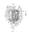
- FIG. 7is a top view, partially in cross-section of an eight cylinder engine of the present invention.
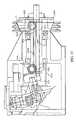
- FIG. 8is a side view in cross-section of the engine of FIG. 7 ;
- FIG. 9is a right end view of FIG. 7 ;
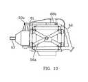
- FIG. 10is a side view of FIG. 7 ;
- FIG. 11is a left end view of FIG. 7 ;
- FIG. 12is a partial top view of the engine of FIG. 7 showing the pistons, drive member and flywheel in a high compression position;
- FIG. 13is a partial top view of the engine in FIG. 7 showing the pistons, drive member and flywheel in a low compression position;
- FIG. 14is a top view of a piston
- FIG. 15is a side view of a piston showing the drive member in two positions
- FIG. 16shows the bearing interface of the drive member and the piston
- FIG. 17is an air driven engine/pump embodiment
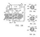
- FIG. 18illustrates the air valve in a first position
- FIGS. 18 a , 18 b and 18 care cross-sectional view of three cross-sections of the air valve shown in FIG. 18 ;
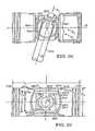
- FIG. 19illustrates the air valve in a second position
- FIGS. 19 a , 19 b and 19 care cross-sectional view of three cross-sections for the air valve shown in FIG. 19 ;
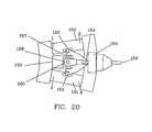
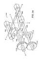
- FIG. 20shows an embodiment with slanted cylinders
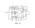
- FIG. 21shows an embodiment with single ended pistons
- FIG. 22is a top view of a two cylinder, double ended piston assembly
- FIG. 23is a top view of one of the double ended pistons of the assembly of FIG. 22 ;
- FIG. 23 ais a side view of the double ended piston of FIG. 23 , taken along lines 23 A, 23 A;
- FIG. 24is a top view of a transition arm and universal joint of the piston assembly of FIG. 22 ;
- FIG. 24 ais a side view of the transition arm and universal joint of FIG. 24 , taken along lines 24 a , 24 a;
- FIG. 25is a perspective view of a drive arm connected to the transition arm of the piston assembly of FIG. 22 ;
- FIG. 25 ais an end view of a rotatable member of the piston assembly of FIG. 22 , taken along lines 25 a , 25 a of FIG. 22 , and showing the connection of the drive arm to the rotatable member;
- FIG. 25 bis a side view of the rotatable member, taken along lines 25 b , 25 b of FIG. 25 a;
- FIG. 26is a cross-sectional, top view of the piston assembly of FIG. 22 ;
- FIG. 27is an end view of the transition arm, taken along lines 27 , 27 of FIG. 24 ;
- FIG. 27 ais a cross-sectional view of a drive pin of the piston assembly of FIG. 22 ;
- FIGS. 28-28 bare top, rear, and side views, respectively, of the piston assembly of FIG. 22 ;
- FIG. 28 cis a top view of an auxiliary shaft of the piston assembly of FIG. 22 ;
- FIG. 29is a cross-sectional side view of a zero-stroke coupling
- FIG. 29 ais an exploded view of the zero-stroke coupling of FIG. 29 ;
- FIG. 30is a graph showing the figure 8 motion of a non-flat piston assembly
- FIG. 31shows a reinforced drive pin
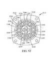
- FIG. 32is a top view of a four cylinder engine for directly applying combustion pressures to pump pistons
- FIG. 32 ais an end view of the four cylinder engine, taken along lines 32 a , 32 a of FIG. 32 ;
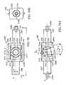
- FIG. 33is a cross-sectional top view of an alternative embodiment of a variable stroke assembly shown in a maximum stroke position
- FIG. 34is a cross-sectional top view of the embodiment of FIG. 33 shown in a minimum stroke position
- FIG. 35is a partial, cross-sectional top view of an alternative embodiment of a double-ended piston joint
- FIG. 35Ais an end view and FIG. 35B is a side view of the double-ended piston joint, taken along lines 35 A, 35 A and 35 B, 35 B, respectively, of FIG. 35 ;
- FIG. 36is a partial, cross-sectional top view of the double-ended piston joint of FIG. 35 shown in a rotated position;
- FIG. 37is a side view of an alternative embodiment of the joint of FIG. 35 ;
- FIG. 38is a top view of an engine/compressor assembly
- FIG. 38Ais an end view and FIG. 38B is a side view of the engine/compressor assembly, taken along lines 38 A, 38 A and 38 B, 38 B, respectively, of FIG. 38 ;
- FIG. 39is a perspective view of a piston engine assembly including counterbalancing
- FIG. 40is a perspective view of the piston engine assembly of FIG. 39 in a second position
- FIG. 41is a perspective view of an alternative embodiment of a piston engine assembly including counterbalancing
- FIG. 42is a perspective view of the piston engine assembly of FIG. 41 in a second position.
- FIG. 43is a perspective view of an additional alternative embodiment of a piston engine assembly including counterbalancing
- FIG. 44is a perspective view of the piston engine assembly of FIG. 43 in a second position
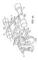
- FIG. 45is a perspective view of an additional alternative embodiment of a piston engine assembly including counterbalancing
- FIG. 46is a perspective view of the piston engine assembly of FIG. 43 in a second position
- FIG. 47is a side view showing the coupling of a transition arm to a flywheel
- FIG. 48is a side view of an alternative coupling of the transition arm to the flywheel
- FIG. 49is a side view of an additional alternative coupling of the transition arm to the flywheel.
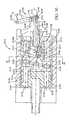
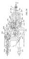
- FIG. 50is a cross-sectional side view of a hydraulic pump
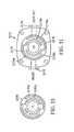
- FIG. 51is an end view of a face valve of the hydraulic pump of FIG. 50 ;
- FIG. 52is a cross-sectional view of the hydraulic pump of FIG. 30 , taken along lines 52 — 52 ;
- FIG. 53is an end view of a face plate of the hydraulic pump of FIG. 50 ;
- FIG. 54is a partially cut-away side view of a variable compression piston assembly
- FIG. 55is a cross-sectional side view of the piston assembly of FIG. 54 , taken along lines 55 — 55 ;
- FIG. 56is a side view of an alternative embodiment of a piston joint
- FIGS. 56A and 56Bare top and end views, respectively, of the piston joint of FIG. 56 ;
- FIG. 56Cis an exploded perspective view of the piston joint of FIG. 56 ;
- FIG. 56Dis an exploded view of inner and outer members of the piston joint of FIG. 56 ;
- FIGS. 56E and 56Fare side and inner face views, respectively, of an outer member of the piston joint of FIG. 56 ;
- FIG. 57illustrates the piston assembly of FIG. 54 with a balance member
- FIG. 58is an illustration of a metering pump
- FIG. 59is a simplified, isometric view of the metering pump of FIG. 58 with components removed for ease of illustration.
- FIG. 1is a pictorial representation of a four piston engine 10 of the present invention.
- Engine 10has two cylinders 11 ( FIG. 3 ) and 12 .
- Each cylinder 11 and 12house a double ended piston.
- Each double ended pistonis connected to transition arm 13 which is connected to flywheel 15 by shaft 14 .
- Transition arm 13is connected to support 19 by a universal joint mechanism, including shaft 18 , which allows transition arm 13 to move up an down and shaft 17 which allows transition arm 13 to move side to side.
- FIG. 1shows flywheel 15 in a position shaft 14 at the top of wheel 15 .
- FIG. 2shows engine 10 with flywheel 15 rotated so that shaft 14 is at the bottom of flywheel 15 .
- Transition arm 13has pivoted downward on shaft 18 .
- FIGS. 3-6show a top view of the pictorial representation, showing the transition arm 13 in four positions and shaft moving flywheel 15 in 90° increments.
- FIG. 3shows flywheel 15 with shaft 14 in the position as illustrated in FIG. 3 a .
- Shaft 14will be in the position shown in FIG. 4 a .
- piston 4is fired, transition arm 13 will move to the position shown in FIG. 5 .
- Flywheel 15 and shaft 14will be in the position shown in FIG. 5 a .
- piston 2will fire and transition arm 13 will be moved to the position shown in FIG. 6 .
- Flywheel 15 and shaft 14will be in the position shown in FIG. 6 a .
- transition arm 13 and flywheel 15will return to the original position that shown in FIGS. 3 and 3 a.
- transition arm 13When the pistons fire, transition arm will be moved back and forth with the movement of the pistons. Since transition arm 13 is connected to universal joint 16 and to flywheel 15 through shaft 14 , flywheel 15 rotates translating the linear motion of the pistons to a rotational motion.
- FIG. 7shows (in partial cross-section) a top view of an embodiment of a four double piston, eight cylinder engine 30 according to the present invention.
- the engineis equivalent to a eight cylinder engine.
- Two cylinders 31 and 46are shown.
- Cylinder 31has double ended piston 32 , 33 with piston rings 32 a and 33 a , respectively.
- Pistons 32 , 33are connected to a transition arm 60 ( FIG. 8 ) by piston arm 54 a extending into opening 55 a in piston 32 , 33 and sleeve bearing 55 .
- piston 47 , 49 , in cylinder 46is connected by piston arm 54 b to transition arm 60 .
- Each end of cylinder 31has inlet and outlet valves controlled by a rocker arms and a spark plug.
- Piston end 32has rocker arms 35 a and 35 b and spark plug 44
- piston end 33has rocker arms 34 a and 34 b , and spark plug 41 .
- Each pistonhas associated with it a set of valves, rocker arms and a spark plug. Timing for firing the spark plugs and opening and closing the inlet and exhaust values is controlled by a timing belt 51 which is connected to pulley 50 a .
- Pulley 50 ais attached to a gear 64 by shaft 63 ( FIG. 8 ) turned by output shaft 53 powered by flywheel 69 .
- Belt 50 aalso turns pulley 50 b and gear 39 connected to distributor 38 .
- Gear 39also turns gear 40 .
- Gears 39 and 40are attached to cam shaft 75 ( FIG. 8 ) which in turn activate push rods that are attached to the rocker arms 34 , 35 and other rocker arms not illustrated.
- FIG. 8is a side view of engine 30 , with one side removed, and taken through section 8 — 8 of FIG. 7 .
- Transitions arm 60is mounted on support 70 by pin 72 which allows transition arm to move up and down (as viewed in FIG. 8 ) and pin 71 which allows transition arm 60 to move from side to side. Since transition arm 60 can move up and down while moving side to side, then shaft 61 can drive flywheel 69 in a circular path.
- the four connecting piston arms(piston arms 54 b and 54 d shown in FIG. 8 ) are driven by the four double end pistons in an oscillator motion around pin 71 .
- the end of shaft 61 in flywheel 69causes transition arm to move up and down as the connection arms move back and forth.
- Flywheel 69has gear teeth 69 a around one side which may be used for turning the flywheel with a starter motor 100 ( FIG. 11 ) to start the engine.
- Push rods 77 , 76 , 93 , 94 , 95 , 96 and 78 , 79are for opening and closing the intake and exhaust valves of the cylinders above the pistons.
- the left side of the engine, which has been cutaway,contains an identical, but opposite valve drive mechanism.
- Gear 66 turned by gear 65 on drive shaft 68turns pump 67 , which may be, for example, a water pump used in the engine cooling system (not illustrated), or an oil pump.
- FIG. 9is a rear view of engine 30 showing the relative positions of the cylinders and double ended pistons.
- Piston 32 , 33is shown in dashed lines with valves 35 c and 35 d located under lifter arms 35 a and 35 b , respectively.
- Belt 51 and pulley 50 bare shown under distributor 38 .
- Transition arm 60 and two, 54 c and 54 d , of the four piston arms 54 a , 54 b , 54 c and 54 dare shown in the pistons 32 - 33 , 32 a - 33 a , 47 - 49 and 47 a - 49 a.
- FIG. 10is a side view of engine 30 showing the exhaust manifold 56 , intake manifold 56 a and carburetor 56 c . Pulleys 50 a and 50 b with timing belt 51 are also shown.
- FIG. 11is a front end view of engine 30 showing the relative positions of the cylinders and double ended pistons 32 - 33 , 32 a - 33 a , 47 - 49 and 47 a - 49 a with the four piston arms 54 a , 54 b , 54 c and 54 d positioned in the pistons.
- Pump 67is shown below shaft 53
- pulley 50 a and timing belt 51are shown at the top of engine 30 .
- Starter 100is shown with gear 101 engaging the gear teeth 69 a on flywheel 69 .
- a feature of the inventionis that the compression ratio for the engine can be changed while the engine is running.
- the end of arm 61 mounted in flywheel 69travels in a circle at the point where arm 61 enters flywheel 69 .
- the end of arm 61is in a sleeve bearing ball bushing assembly 81 .
- the stroke of the pistonsis controlled by arm 61 .
- Arm 61forms an angle, for example about 15°, with shaft 53 .
- flywheel 69By is moving flywheel 69 on shaft 53 to the right or left, as viewed in FIG. 13 , the angle of arm 61 can be changed, changing the stroke of the pistons, changing the compression ratio.
- the position of flywheel 69is changed by turning nut 104 on threads 105 .
- Nut 104is keyed to shaft 53 by thrust bearing 106 a held in place by ring 106 b . In the position shown in FIG. 12 , flywheel 69 has been moved to the right, extending the stroke
- FIG. 12shows flywheel moved to the right increasing the stroke of the pistons, providing a higher compression ratio.
- Nut 105has been screwed to the right, moving shaft 53 and flywheel 69 to the right.
- Arm 61extends further into bushing assembly 80 and out the back of flywheel 69 .
- FIG. 13shows flywheel moved to the left reducing the stroke of the pistons, providing a lower compression ratio.
- Nut 105has been screwed to the left, moving shaft 53 and flywheel 69 to the left.
- Arm 61extends less into bushing assembly 80 .
- FIG. 14shows a double piston 110 having piston rings 111 on one end of the double piston and piston rings 112 on the other end of the double piston.
- a slot 113is in the side of the piston. The location the sleeve bearing is shown at 114 .
- FIG. 15shows a piston arm 116 extending into piston 110 through slot 116 into sleeve bearing 117 in bushing 115 .
- Piston arm 116is shown in a second position at 116 a .
- the two pistons arms 116 and 116 ashow the movement limits of piston arm 116 during operation of the engine.
- FIG. 16shows piston arm 116 in sleeve bearing 117 .
- Sleeve bearing 117is in pivot pin 115 .
- Piston arm 116can freely rotate in sleeve bearing 117 and the assembly of piston arm 116 .
- Sleeve bearing 117 and pivot pin 115 and sleeve bearings 118 a and 118 brotate in piston 110 , and piston arm 116 can be moved axially with the axis of sleeve bearing 117 to allow for the linear motion of double ended piston 110 , and the motion of a transition arm to which piston arm 116 is attached.
- FIG. 17shows how the four cylinder engine 10 in FIG. 1 may be configured as an air motor using a four way rotary valve 123 on the output shaft 122 .
- Each of cylinders 1 , 2 , 3 and 4are connected by hoses 131 , 132 , 133 , and 144 , respectively, to rotary valve 123 .
- Air inlet port 124is used to supply air to run engine 120 . Air is sequentially supplied to each of the pistons 1 a , 2 a , 3 a and 4 a , to move the pistons back and forth in the cylinders. Air is exhausted from the cylinders out exhaust port 136 .
- Transition arm 126attached to the pistons by connecting pins 127 and 128 are moved as described with references to FIGS. 1-6 to turn flywheel 129 and output shaft 22 .
- FIG. 18is a cross-sectional view of rotary valve 123 in the position when pressurized air or gas is being applied to cylinder 1 through inlet port 124 , annular channel 125 , channel 126 , channel 130 , and air hose 131 .
- Rotary valve 123is made up of a plurality of channels in housing 123 and output shaft 122 .
- the pressurized air entering cylinder 1causes piston 1 a , 3 a to move to the right (as viewed in FIG. 18 ).
- Exhaust airis forced out of cylinder 3 through line 133 into chamber 134 , through passageway 135 and out exhaust outlet 136 .
- FIGS. 18 a , 18 b and 18 care cross-sectional view of valve 23 showing the air passages of the valves at three positions along valve 23 when positioned as shown in FIG. 18 .
- FIG. 19shows rotary valve 123 rotated 180° when pressurized air is applied to cylinder 3 , reversing the direction of piston 1 a , 3 a .
- Pressurized airis applied to inlet port 124 , through annular chamber 125 , passage way 126 , chamber 134 and air line 133 to cylinder 3 .
- Thisin turn causes air in cylinder 1 to be exhausted through line 131 , chamber 130 , line 135 , annular chamber 137 and out exhaust port 136 .
- Shaft 122will have rotated 360° turning counter clockwise when piston 1 a , 3 a complete it stroke to the left.
- piston 1 a , 3 aOnly piston 1 a , 3 a have been illustrated to show the operation of the air engine and valve 123 relative to the piston motion.
- the operation of piston 2 a , 4 ais identical in function except that its 360° cycle starts at 90° shaft rotation and reverses at 270° and completes its cycle back at 90°. A power stroke occurs at every 90° of rotation.
- FIGS. 19 a , 19 b and 19 care cross-sectional views of valve 123 showing the air passages of the valves at three positions along valve 123 when positioned as shown in FIG. 19 .
- engine 120 of FIG. 17can be used as an air or gas compressor or pump.
- exhaust port 136will draw in air into the cylinders and port 124 will supply air which may be used to drive, for example air tool, or be stored in an air tank.
- FIG. 20shows an embodiment similar to the embodiment of FIGS. 1-6 , with cylinders 150 and 151 not parallel to each other.
- Universal joint 160permits the piston arms 152 and 153 to be at an angle other than 90° to the drive arm 154 . Even with the cylinders not parallel to each other the engines are functionally the same.
- FIG. 21Still another modification may be made to the engine 10 of FIGS. 1-6 .
- This embodimentpictorially shown in FIG. 21 , may have single ended pistons. Piston 1 a and 2 a are connected to universal joint 170 by drive arms 171 and 172 , and to flywheel 173 by drive arm 174 . The basic difference is the number of strokes of pistons 1 a and 2 a to rotate flywheel 173 360°.
- a two cylinder piston assembly 300includes cylinders 302 , 304 , each housing a variable stroke, double ended piston 306 , 308 , respectively.
- Piston assembly 300provides the same number of power strokes per revolution as a conventional four cylinder engine.
- Each double ended piston 306 , 308is connected to a transition arm 310 by a drive pin 312 , 314 , respectively.
- Transition arm 310is mounted to a support 316 by, e.g., a universal joint 318 (U-joint), constant velocity joint, or spherical bearing.
- a drive arm 320 extending from transition arm 310is connected to a rotatable member, e.g., flywheel 322 .
- Transition arm 310transmits linear motion of pistons 306 , 308 to rotary motion of flywheel 322 .
- the axis, A, of flywheel 322is parallel to the axes, B and C, of pistons 306 , 308 (though axis, A, could be off-axis as shown in FIG. 20 ) to form an axial or barrel type engine, pump, or compressor.
- U-joint 318is centered on axis, A.
- pistons 306 , 308are 180? apart with axes A, B and C lying along a common plane, D, to form a flat piston assembly.
- cylinders 302 , 304each include left and right cylinder halves 301 a , 301 b mounted to the assembly case structure 303 .
- Double ended pistons 306 , 308each include two pistons 330 and 332 , 330 a and 332 a , respectively, joined by a central joint 334 , 334 a , respectively.
- the pistonsare shown having equal length, though other lengths are contemplated.
- joint 334can be off-center such that piston 330 is longer than piston 332 .
- flywheel 322is rotated in a clockwise direction, as viewed in the direction of arrow 333 .
- Piston assembly 300is a four stroke cycle engine, i.e., each piston fires once in two revolutions of flywheel 322 .
- drive pins 312 , 314must be free to rotate about their common axis, E, (arrow 305 ), slide along axis, E, (arrow 307 ) as the radial distance to the center line, B, of the piston changes with the angle of swing, ⁇ , of transition arm 310 (approximately ⁇ 15° swing), and pivot about centers, F, (arrow 309 ).
- Joint 334is constructed to provide this freedom of motion.
- Joint 334defines a slot 340 ( FIG. 23 a ) for receiving drive pin 312 , and a hole 336 perpendicular to slot 340 housing a sleeve bearing 338 .
- a cylinder 341is positioned within sleeve bearing 338 for rotation within the sleeve bearing.
- Sleeve bearing 338defines a side slot 342 shaped like slot 340 and aligned with slot 340 .
- Cylinder 341defines a through hole 344 .
- Drive pin 312is received within slot 342 and hole 344 .
- An additional sleeve bearing 346is located in through hole 344 of cylinder 341 .
- the combination of slots 340 and 342 and sleeve bearing 338permit drive pin 312 to move along arrow 309 .
- Sleeve bearing 346permits drive pin 312 to rotate about its axis, E, and slide along its axis, E.
- an alternative embodiment of a central joint 934 for joining pistons 330 and 332is configured to produce zero side load on pistons 330 and 332 .
- Joint 934permits the four degrees of freedom necessary to prevent binding of drive pin 312 as the pistons move back and forth, i.e., rotation about axis, E, (arrow 905 ), pivoting about center, F, (arrow 909 ), and sliding movement along orthogonal axes, M (up and down in the plane of the paper in FIG. 35 ) and N (in and out of the plane of the paper in FIG. 35 ), while the load transmitted between joint 934 and pistons 330 , 332 only produces a force vector which is parallel to piston axis, B (which is orthogonal to axes M and N).
- Joint 934defines two opposed flat faces 937 , 937 a which slide in the directions of axes M and N relative to pistons 330 , 332 . Faces 937 , 937 a define parallel planes which remain perpendicular to piston axis, B, during the back and forth movement of the pistons.
- Joint 934includes an outer slider member 935 which defines faces 937 , 937 a for receiving the driving force from pistons 330 , 332 .
- Slider member 935defines a slot 940 in a third face 945 of the slider for receiving drive pin 312 , and a slot 940 a in a fourth face 945 a .
- Slider member 935has an inner wall 936 defining a hole 939 perpendicular to slot 940 and housing a slider sleeve bearing 938 .
- a cross shaft 941is positioned within sleeve bearing 938 for rotation within the sleeve bearing in the direction of arrow 909 .
- Sleeve bearing 938defines a side slot 942 shaped like slot 940 and aligned with slot 940 .
- Cross shaft 941defines a through hole 944 .
- Drive pin 312is received within slot 942 and hole 944 .
- a sleeve bearing 946is located in through hole 944 of cross shaft 941
- slots 940 and 942 and sleeve bearing 938permit drive pin 312 to move in the direction of arrow 909 .
- a cap screw 947 and washer 949Positioned within slot 940 a is a cap screw 947 and washer 949 which attach to drive pin 312 retaining drive pin 312 against a step 951 defined by cross shaft 941 while permitting drive pin 312 to rotate about its axis, E, and preventing drive pin 312 from sliding along axis, E.
- the two addition freedoms of motionare provided by sliding of slider faces 937 , 937 a relative to pistons 330 , 332 along axis, M and N.
- a plate 960is placed between each of face 937 and piston 330 and face 937 a and piston 332 .
- Each plate 960is formed of a low friction bearing material with a bearing surface 962 in contact with faces 937 , 937 a , respectively. Faces 937 , 937 a are polished.
- the load, P L , applied to joint 934 by piston 330 in the direction of piston axis, B,is resolved into two perpendicular loads acting on pin 312 : axial load, A L , along the axis, E, of drive pin 312 , and normal load, N L , perpendicular to drive pin axis, E.
- the axial loadis applied to thrust bearings 950 , 952
- the normal loadis applied to sleeve bearing 946 .
- the net direction of the forces transmitted between pistons 330 , 332 and joint 934remains along piston axis, B, preventing side loads being applied to pistons 330 , 332 . This is advantageous because side loads on pistons 330 , 332 can cause the pistons to contact the cylinder wall creating frictional losses proportional to the side load values.
- Pistons 330 , 332are mounted to joint 934 by a center piece connector 970 .
- Center piece 970includes threaded ends 972 , 974 for receiving threaded ends 330 a and 332 a of the pistons, respectively.
- Center piece 970defines a cavity 975 for receiving joint 934 .
- a gap 976is provided between joint 934 and center piece 970 to permit motion along axis, N.
- joint 934For an engine capable of producing, e.g., about 100 horsepower, joint 934 has a width, W, of, e.g., about 3 ⁇ fraction (5/16) ⁇ inches, a length, L 1 , of, e.g., 3 ⁇ fraction (5/16) ⁇ inches, and a height, H, of, e.g., about 31 ⁇ 2 inches.
- the joint and piston ends togetherhave an overall length, L 2 , of, e.g., about 9 ⁇ fraction (5/16) ⁇ inches, and a diameter, D 1 , of, e.g., about 4 inches.
- Plates 960have a diameter, D 2 , of, e.g., about 31 ⁇ 4 inch, and a thickness, T, of, e.g., about 1 ⁇ 8 inch. Plates 960 are press fit into the pistons. Plates 960 are preferably bronze, and slider 935 is preferably steel or aluminum with a steel surface defining faces 937 , 937 a.
- Joint 934need not be used to join two pistons.
- One of pistons 330 , 332can be replaced by a rod guided in a bushing.
- joint 934need not slide in the direction of axis, N.
- slider member 935 a and plates 960 ahave curved surfaces permitting slider member 935 a to slide in the direction of axis, M, (in and out of the paper in FIG. 37 ) while preventing slider member 935 a to move along axis, N.
- a piston joint 2300includes a housing 2302 , an outer member 2304 having first and second parts 2304 a , 2304 b , and an inner cylindrical member 2306 .
- Housing 2302includes extensions 2308 and a rectangular shaped enclosure 2310 .
- one extension 2308includes a mount 2308 a to which a piston or plunger (not shown) is coupled, with the opposite extension 2308 acting as guide rods.
- both extensions 2308are shown with mounts 2308 a to which a double-ended piston or plunger is coupled.
- Enclosure 2310defines a rectangular shaped opening 2312 ( FIG. 56C ) in which outer member 2304 and inner member 2306 are positioned. Opening 2312 is defined by four flat inner walls 2312 a , 2312 b , 2312 c , 2312 d of enclosure 2310 .
- parts 2304 a , 2304 beach have a flat outer, end wall 2314 , defining a plane perpendicular to an axis, X, defined by mounts 2308 , two parallel flat sides 2316 , and two curved side walls 2318 .
- Parts 2304 a , 2304 balso have an inner end wall 2320 with a concave cut-out 2322 .
- concave cut-outs 2322define an opening 2322 a ( FIG. 56A ) between parts 2304 a , 2304 b for receiving inner member 2306 .
- Inner end wall 2320also defines two, sloped concave cut-outs 2324 perpendicular to cut-outs 2322 and positioned between sloped edges 2326 , for purposes described below.
- Parts 2304 a , 2304 bare sized relative to opening 2312 to be free to slide along an axis, Y, perpendicular to axis, X, (arrow A), but are restricted by walls 2312 a , 2312 b from sliding along an axis, Z, perpendicular to axes, X and Y (arrow B).
- Inner member 2306defines a through hole 2330 for receiving a transition arm drive arm 2332 .
- Inner member 2306is shorter in the Z direction than opening 2312 in housing 2302 such that inner member 2306 can slide within opening 2312 along axis, Z, (arrow B).
- a sleeve bearing 2334Located between drive arm 2332 and inner member 2306 is a sleeve bearing 2334 which facilitates rotation of drive arm 2332 relative to inner member 2306 about axis, Y, arrow (D) (FIG. 56 D).
- Drive arm 2332is coupled to inner member 2306 by a threaded stud 2338 , washer 2340 , nut 2342 , and thrust washers 2344 and 2346 . Stud 2338 is received within a threaded hole 2339 in arm 2332 .
- Inner member 2306is countersunk at 2306 a to receive washer 2346 .
- Thrust washer 2346includes a tab 2348 received in a notch (not shown) in inner member 2306 to prevent rotation of thrust washer 2346 relative to inner member 2306 .
- Thrust washer 2344is formed, e.g., of steel, with a polished surface facing thrust washer 2346 .
- Thrust washer 2346has, e.g., a Teflon surface facing thrust washer 2344 to provide low friction between washers 2344 and 2346 , and a copper backing.
- An additional thrust washer 2350formed, e.g., of bronze, is positioned between inner member 2306 and the transition arm.
- Piston joint 2300includes an oil path 2336 ( FIG. 56A ) for flow of lubrication.
- Arm 2332 , inner member 2306 , outer member parts 2304 a and 2304 b , and bearing 2334include through holes 2352 that define oil path 2336 .
- bearing 2334can be formed from two rings with a gap between the rings for flow of oil.
- outer member 2304 and inner member 2306slide together relative to housing 2302 along axis, Y, (arrow A), inner member 2306 slides relative to outer member 2304 along axis, Z, (arrow B), inner member 2306 rotates relative to outer member 2304 about axis, Z, (arrow C), and drive arm 2332 rotates relative to inner member 2306 about axis, Y, (arrow D).
- Loadis transferred between outer member 2304 and housing 2302 along vectors parallel to axis, X, by flat sides 2314 of outer member 2304 and flat walls 2312 c and 2312 d of housing 2302 , thus limiting the transfer of any side loads to the pistons.
- motion of drive arm 2332can also cause inner member 2306 to rotate about axis, X.
- axis, XFor example, in a three cylinder pump, with the top cylinder in line with the U-joint fixed axis, and the second and third cylinders spaced 120 degrees, the drive arms for the second and third cylinders undergo a twisting motion which is part of the figure 8 motion describe above. This motion causes rotation of inner member 2306 of the respective joints about axis, X. This twisting motion is taking place at twice the rpm frequency. Unless further steps are taken, housing 2302 and the pistons would also twist about axis, X, at twice the rpm frequency. Inner member 2306 of the joint for the top piston does not undergo twist about axis, X, because its drive pin is confined to motion in a straight line by the U-joint.
- outer member 935is free to rotate about axis, B (corresponding to axis, X of FIG. 56 ), thus the twisting motion of the drive arm is not transferred to the pistons.
- outer member 2304is restrained from moving in the direction of axis, Z, curved side walls 2318 of parts 2304 a , 2304 b are provided for accommodating the motion about axis, X.
- walls 2318are radiused over an angle, ⁇ , of about ⁇ 2°, that blends into a tangent plane at the same 2° angle on both sides of a center line, L.
- curved side walls 2318have radiused sections which extend the minimum amount necessary to limit transfer of the motion about axis, X, to housing 2302 .
- Outer member 2304acts to nudge the piston to a set angle on the first revolution of the engine or pump. If the piston deviates from that angle, the piston is forced back by the action of outer member 2304 at the end of travel of the piston.
- the contact between curved walls 2318 and side walls 2312 a , 2312 b of housing 2302is a line contact, but this contact has no work to do in normal use, and the contact line moves on both parts, distributing any wear taking place.
- U-joint 318defines a central pivot 352 (drive pin axis, E, passes through center 352 ), and includes a vertical pin 354 and a horizontal pin 356 .
- Transition arm 310is capable of pivoting about pin 354 along arrow 358 , and about pin 356 along arrow 360 .
- drive arm 320is received within a cylindrical pivot pin 370 mounted to the flywheel offset radially from the center 372 of the flywheel by an amount, e.g., 2.125 inches, required to produce the desired swing angle, ⁇ (FIG. 22 ), in the transition arm.
- Pivot pin 370has a through hole 374 for receiving drive arm 320 . There is a sleeve bearing 376 in hole 374 to provide a bearing surface for drive arm 320 . Pivot pin 370 has cylindrical extensions 378 , 380 positioned within sleeve bearings 382 , 384 , respectively. As the flywheel is moved axially along drive arm 320 to vary the swing angle, ⁇ , and thus the compression ratio of the assembly, as described further below, pivot pin 370 rotates within sleeve bearings 382 , 384 to remain aligned with drive arm 320 . Torsional forces are transmitted through thrust bearings 388 , 390 , with one or the other of the thrust bearings carrying the load depending on the direction of the rotation of the flywheel along arrow 386 .
- flywheel 322 along axis, Ais varied by rotating a shaft 400 .
- a sprocket 410is mounted to shaft 400 to rotate with shaft 400 .
- a second sprocket 412is connected to sprocket 410 by a roller chain 413 .
- Sprocket 412is mounted to a threaded rotating barrel 414 . Threads 416 of barrel 414 contact threads 418 of a stationary outer barrel 420 .
- outer barrel 420is fixed, the rotation of barrel 414 causes barrel 414 to move linearly along axis, A, arrow 403 .
- Barrel 414is positioned between a collar 422 and a gear 424 , both fixed to a main drive shaft 408 .
- Drive shaft 408is in turn fixed to flywheel 322 .
- movement of barrel 414 along axis, Ais translated to linear movement of flywheel 322 along axis, A.
- Thrust bearings 430are located at both ends of barrel 414 , and a sleeve bearing 432 is located between barrel 414 and shaft 408 .
- shaft 400is threaded at region 402 and is received within a threaded hole 404 of a cross bar 406 of assembly case structure 303 .
- the ratio of the number of teeth of sprocket 412 to sprocket 410is, e.g., 4:1. Therefore, shaft 400 must turn four revolutions for a single revolution of barrel 414 .
- threaded region 402must have four times the threads per inch of barrel threads 416 , e.g., threaded region 402 has thirty-two threads per inch, and barrel threads 416 have eight threads per inch.
- the stroke of the pistons, and thus the compression ratiois increased. Moving the flywheel to the left decreases the stroke and the compression ratio.
- a further benefit of the change in strokeis a change in the displacement of each piston and therefore the displacement of the engine.
- the horsepower of an internal combustion engineclosely relates to the displacement of the engine. For example, in the two cylinder, flat engine, the displacement increases by about 20% when the compression ratio is raised from 6:1 to 12:1. This produces approximately 20% more horsepower due alone to the increase in displacement.
- the increase in compression ratioalso increases the horsepower at the rate of about 5% per point or approximately 25% in horsepower. If the horsepower were maintained constant and the compression ratio increased from 6:1 to 12:1, there would be a reduction in fuel consumption of approximately 25%.
- the flywheelhas sufficient strength to withstand the large centrifugal forces seen when assembly 300 is functioning as an engine.
- the flywheel position, and thus the compression ratio of the piston assembly,can be varied while the piston assembly is running.
- Piston assembly 300includes a pressure lubrication system.
- the pressureis provided by an engine driven positive displacement pump (not shown) having a pressure relief valve to prevent overpressures.
- Bearings 430 and 432 of drive shaft 408 and the interface of drive arm 320 with flywheel 322are lubricated via ports 433 (FIG. 26 ).
- holes 460 , 462 in each pinconnect through slots 461 and ports 463 through sleeve bearing 338 to a chamber 465 in each piston.
- Several oil lines 464feed out from these chambers and are connected to the skirt 466 of each piston to provide lubrication to the cylinders walls and the piston rings 467 .
- Also leading from chamber 465is an orifice to squirt oil directly onto the inside of the top of each piston for cooling.
- the engine ignitionincludes two magnetos 600 to fire the piston spark plugs (not shown).
- Magnetos 600 and a starter 602are driven by drive gears 604 and 606 ( FIG. 28 c ), respectively, located on a lower shaft 608 mounted parallel and below the main drive shaft 408 .
- Shaft 608extends the full length of the engine and is driven by gear 424 ( FIG. 26 ) of drive shaft 408 and is geared with a one to one ratio to drive shaft 408 .
- the gearing for the magnetosreduces their speed to half the speed of shaft 608 .
- Starter 602is geared to provide sufficient torque to start the engine.
- Camshafts 610operate piston push rods 612 through lifters 613 .
- Camshafts 610are geared down 2 to 1 through bevel gears 614 , 616 also driven from shaft 608 .
- Center 617 of gears 614 , 616is preferably aligned with U-joint center 352 such that the camshafts are centered in the piston cylinders, though other configurations are contemplated.
- a single carburetor 620is located under the center of the engine with four induction pipes 622 routed to each of the four cylinder intake valves (not shown).
- the cylinder exhaust valves (not shown)exhaust into two manifolds 624 .
- Engine 300 ahas a length, L, e.g., of about forty inches, a width, W, e.g., of about twenty-one inches, and a height, H, e.g., of about twenty inches, (excluding support 303 ).
- FIGS. 29 and 29 aa variable compression compressor or pump having zero stroke capability is illustrated.
- flywheel 322is replaced by a rotating assembly 500 .
- Assembly 500includes a hollow shaft 502 and a pivot arm 504 pivotally connected by a pin 506 to a hub 508 of shaft 502 .
- Hub 508defines a hole 510 and pivot arm 504 defines a hole 512 for receiving pin 506 .
- a control rod 514is located within shaft 502 .
- Control rod 514includes a link 516 pivotally connected to the remainder of rod 514 by a pin 518 .
- Rod 514defines a hole 511 and link 516 defines a hole 513 for receiving pin 518 .
- Control rod 514is supported for movement along its axis, Z, by two sleeve bearings 520 .
- Link 516 and pivot arm 514are connected by a pin 522 .
- Link 516defines a hole 523 and pivot arm 514 defines a hole 524 for receiving pin 522 .
- Cylindrical pivot pin 370 of FIG. 25 which receives drive arm 320is positioned within pivot arm 504 .
- Pivot arm 504defines holes 526 for receiving cylindrical extensions 378 , 380 .
- Shaft 502is supported for rotation by bearings 530 , e.g., ball, sleeve, or roller bearings.
- a drive, e.g., pulley 532 or gears, mounted to shaft 502drives the compressor or pump.
- control rod 514is moved along its axis, M, in the direction of arrow 515 , causing pivot arm 504 to pivot about pin 506 , along arrow 517 , such that pivot pin 370 axis, N, is moved out of alignment with axis, M, (as shown in dashed lines) as pivot arm 504 slides along the axis, H, ( FIG. 26 ) of the transition arm drive arm 320 .
- axes M and Nare aligned such that rotation of shaft 514 does not cause movement of the pistons. This configuration works for both double ended and single sided pistons.
- the ability to vary the piston strokepermits shaft 514 to be run at a single speed by drive 532 while the output of the pump or compressor can be continually varied as needed.
- pivot arm 504simply spins around drive arm 320 of transition arm 310 with zero swing of the drive arm.
- shaft 514is already running at full speed so that when pivot arm 504 is pulled off-axis by control rod 514 , an immediate stroke is produced with no lag coming up to speed. There are therefore much lower stress loads on the drive system as there are no start/stop actions.
- the ability to quickly reduce the stroke to zeroprovides protection from damage especially in liquid pumping when a downstream blockage occurs.
- FIG. 33An alternative method of varying the compression and displacement of the pistons is shown in FIG. 33 .
- the mechanismprovides for varying of the position of a counterweight attached to the flywheel to maintain system balance as the stroke of the pistons is varied.
- a flywheel 722is pivotally mounted to an extension 706 of a main drive shaft 708 by a pin 712 .
- flywheel 722By pivoting flywheel 722 in the direction of arrow, Z, flywheel 722 slides along axis, H, of a drive arm 720 of transition arm 710 , changing angle, ⁇ (FIG. 26 ), and thus the stroke of the pistons.
- Pivoting flywheel 722also causes a counterweight 714 to move closer to or further from axis, A, thus maintaining near rotational balance.
- an axially and rotationally movable pressure plate 820is provided to pivot flywheel 722 .
- Pressure plate 820is in contact with a roller 822 rotationally mounted to counterweight 714 through a pin 824 and bearing 826 .
- a servo motor or hand knob 830turns a screw 832 which advances to move pressure plate 820 in the direction of arrow, Y.
- This motion of pressure plate 820causes flywheel 722 to pivot in the direction of arrow, Z, as shown in the FIG. 34 , to decrease the stroke of the pistons.
- Moving pressure plate 820 by 0.75′′decreases the compression ratio from about 12:1 to about 6:1.
- Pressure plate 820is supported by three or more screws 832 .
- Each screwhas a gear head 840 which interfaces with a gear 842 on pressure plate 820 such that rotation of screw 832 causes rotation of pressure plate 820 and thus rotation of the remaining screws to insure that the pressure plate is adequately supported.
- a piston 850is provided which biases flywheel 722 in the direction opposite to arrow, Z.
- FIG. 30shows the figure 8 motion of a piston assembly having four double ended pistons. Two of the pistons are arranged flat as shown in FIG. 22 (and do not undergo the figure 8 motion), and the other two pistons are arranged equally spaced between the flat pistons (and are thus positioned to undergo the largest figure 8 deviation possible).
- the amount that the pins connected to the second set of pistons deviate from a straight line (y axis of FIG. 30 )is determined by the swing angle (mast angle) of the drive arm and the distance the pin is from the central pivot point 352 (x axis of FIG. 30 ).
- support 550is bolted to transition arm 310 with bolts 551 and includes an opening 552 for receiving end 554 of the pin.
- Engines according to the inventioncan be used to directly apply combustion pressures to pump pistons.
- a four cylinder, two stroke cycle engine 600(each of the four pistons 602 fires once in one revolution) applies combustion pressure to each of four pump pistons 604 .
- Each pump piston 604is attached to the output side 606 of a corresponding piston cylinder 608 .
- Pump pistons 604extend into a pump head 610 .
- a transition arm 620is connected to each cylinder 608 and to a flywheel 622 , as described above.
- An auxiliary output shaft 624is connected to flywheel 622 to rotate with the flywheel, also as described above.
- the engineis a two stroke cycle engine because every stroke of a piston 602 (as piston 602 travels to the right as viewed in FIG. 32 ) must be a power stroke.
- the number of engine cylindersis selected as required by the pump.
- the pumpcan be a fluid or gas pump. In use as a multi-stage air compressor, each pump piston 606 can be a different diameter. No bearing loads are generated by the pumping function (for single acting pump compressor cylinders), and therefore, no friction is introduced other than that generated by the pump pistons themselves.
- an engine 1010 having vibration canceling characteristics and being particularly suited for use in gas compressionincludes two assemblies 1012 , 1014 mounted back-to-back and 180° out of phase.
- Engine 1010includes a central engine section 1016 and outer compressor sections 1018 , 1020 .
- Engine section 1016includes, e.g., six double acting cylinders 1022 , each housing a pair of piston 1024 , 1026 .
- a power strokeoccurs when a center section 1028 of cylinder 1022 is fired, moving pistons 1024 , 1026 away from each other. The opposed movement of the pistons results in vibration canceling.
- Outer compression section 1018includes two compressor cylinders 1030 and outer compression section 1020 includes two compressor cylinders 1032 , though there could be up to six compressor cylinders in each compression section.
- Compression cylinders 1030each house a compression piston 1034 mounted to one of pistons 1024 by a rod 1036
- compression cylinders 1032each house a compression piston 1038 mounted to one of pistons 1026 by a rod 1040 .
- Compression cylinders 1030 , 1032are mounted to opposite piston pairs such that the forces cancel minimizing vibration forces which would otherwise be transmitted into mounting 1041 .
- Pistons 1024are coupled by a transition arm 1042 , and pistons 1026 are coupled by a transition arm 1044 , as described above.
- Transition arm 1042includes a drive arm 1046 extending into a flywheel 1048
- transition arm 1044includes a drive arm 1050 extending into a flywheel 1052 , as described above.
- Flywheel 1048is joined to flywheel 1052 by a coupling arm 1054 to rotate in synchronization therewith.
- Flywheels 1048 , 1052are mounted on bearings 1056 .
- Flywheel 1048includes a bevel gear 1058 which drives a shaft 1060 for the engine starter, oil pump and distributor for ignition, not shown.
- Engine 1010is, e.g., a two stroke natural gas engine having ports (not shown) in central section 1028 of cylinders 1022 and a turbocharger (not shown) which provides intake air under pressure for purging cylinders 1022 .
- engine 1010is gasoline or diesel powered.
- the stroke of pistons 1024 , 1026can be varied by moving both flywheels 1048 , 1052 such that the stroke of the engine pistons and the compressor pistons are adjusted equally reducing or increasing the engine power as the pumping power requirement reduces or increases, respectively.
- vibration canceling characteristics of the back-to-back relationship of assemblies 1012 , 1014can be advantageously employed in a compressor only system and an engine only system.
- an engine 1100includes counterweights 1114 and 1116 .
- Counterweight 1114is mounted to rotate with a rotatable member 1108 , e.g., a flywheel, connected to drive arm 320 extending from transition arm 310 .
- Counterweight 1116is mounted to lower shaft 608 to rotate with shaft 608 .
- Movement of the double ended pistons 306 , 308is translated by transition arm 310 into rotary motion of member 1108 and counterweight 1114 .
- the rotation of member 1108causes main drive shaft 408 to rotate.
- shaft 408is a first gear 1110 which rotates with shaft 408 .
- shaft 608is mounted to lower shaft 608 a second gear 1112 driven by gear 1110 to rotate at the same speed as gear 1110 and in the opposite direction to the direction of rotation of gear 1110 .
- the rotation of gear 1112causes rotation of shaft 608 and thus rotation of counterweight 1116 .
- counterweight 1114rotates clockwise (arrow 1118 ) and counterweight 1116 rotates counterclockwise (arrow 1120 ).
- Counterweights 1114 and 1116are mounted 180 degrees out of phase such that when counterweight 1114 is above shaft 408 , counterweight 1116 is below shaft 608 .
- a quarter turnresults in both counterweights 1114 , 1116 being to the right of their respective shafts (see FIG. 40 ).
- counterweight 1114is below shaft 408 and counterweight 1116 is above shaft 608 .
- Another quarter turn and both counterweightsare to the left of their respective shafts.
- Counterweight 1114also accounts for moments produced by drive arm 320 .
- counterweight 1116is not necessary because at no time is there no moment about the Z axis requiring the moment created by counterweight 1114 to be cancelled.
- FIG. 41Another embodiment of a counterbalancing technique which accounts for all moments is shown in FIG. 41 .
- a counterweight 1114 a mounted to rotating member 1108is sized to only balance transition arm 310 .
- Counterweights 1130 , 1132are provided to counterbalance the inertial forces of double-ended pistons 306 , 308 .
- Counterweight 1130is mounted to gear 1110 to rotate clockwise with gear 1110 .
- Counterweight 1132is driven through a pulley system 1134 to rotate counterclockwise.
- Pulley system 1134includes a pulley 1136 mounted to rotate with shaft 608 , and a chain or timing belt 1138 .
- Counterweight 1132is mounted to shaft 408 by a pulley 1140 and bearing 1142 .
- Counterclockwise rotation of pulley 1136causes counterclockwise rotation of chain or belt 1138 and counterclockwise rotation of counterweight 1132 .
- Counterweights 1130 , 1132are positioned close together along the Y axis to provide near equal moments about the Z axis.
- the weights of counterweights 1130 , 1132can be slightly different to account for their varying location along the Y axis so that each counterweight generates the same moment about the center of gravity of the engine.
- Counterweights 1130 , 1132in addition to providing the desired moments about the Z axis, create undesirable lateral forces directed perpendicular to the Y-axis (in the direction of the X axis), which act on the U-joint or other mount supporting transition arm 310 .
- thisdoes not occur because the upward force, F u , and the downward force, F d , cancel.
- this forceis applied to the mount. For example, as shown in FIG.
- Counterweights 1130 and 1152are mounted to shaft 408 to rotate clockwise with shaft 408 .
- Counterweights 1132 and 1150are mounted to a cylinder 1154 surrounding shaft 408 which is driven through pulley system 1134 to rotate counterclockwise.
- Counterweights 1130 , 1152extend from opposite sides of shaft 408 (counterweight 1130 being directed downward in FIG. 43 , and counterweight 1152 being directed upward), and counterweights 1132 , 1150 extend from opposite sides of cylinder 1154 (counterweight 1132 being directed upward, and counterweight 1150 being directed downward).
- Counterweights 1130 , 1150are aligned on the same side of shaft 408 , and counterweights 1132 , 1152 are aligned on the opposite side of shaft 408 .
- counterweights 1130 , 1132 , 1150 , 1152are substantially the same weight, and counterweights 1150 , 1152 are located further from the Z axis than counterweights 1130 , 1132 , the moment created by counterweights 1150 , 1152 is larger than the moment created by counterweights 1130 , 1132 such that these forces act together to create a moment about the Z axis, M zx , which acts in the opposite direction to M zy .
- the weight of counterweights 1130 , 1132 , 1150 , 1152is selected such that M zx substantially cancels M zy .
- Counterweight 1130can be incorporated into flywheel 1108 , thus eliminating one of the counterweights.
- another configuration for balancing a piston engine having two double ended pistons 306 , 308 180° apart around the Y axisincludes two members 1160 , 1162 , which each simulate a double ended piston, and two counterweights 1164 , 1166 .
- Members 1160 , 1162are 180° apart and equally spaced between pistons 306 , 308 .
- Counterweights 1164 , 1166extend from opposite sides of shaft 408 , with counterweight 1166 being spaced further from the Z axis than counterweight 1164 .
- counterweight 1114 a mounted to rotating member 1108is sized to only balance transition arm 310 .
- counterweights 1164 , 1166are positioned as shown in FIG. 45 , the centrifugal forces due to the rotation of counterweights 1164 , 1166 creates forces, F u and F d , respectively, in opposite directions along the Z axis. Since counterweight 1166 is located further from the Z axis than counterweight 1164 , the moment created by counterweight 1166 is larger than the moment created by counterweight 1164 such that these forces act together to create a moment about the X axis, M xz , which acts in the opposite direction to M xy .
- the weight of counterweights 1164 , 1166is selected such that M xz substantially cancels M xy .
- Counterweight 1164can be incorporated into flywheel 1108 thus eliminating one of the counterweights.
- the piston enginecan include any number of pistons and simulated piston counterweights to provide the desired balancing, e.g., a three piston engine can be formed by replacing one of the simulated piston counterweights in FIG. 43 with a piston, and a two piston engine can be formed with two pistons and one simulated piston counterweight equally spaced about the transition arm.
- transition arm 310Another undesirable force that can be advantageously reduced or eliminated is a thrust load applied by transition arm 310 to flywheel 1108 that is generated by the circular travel of transition arm 310 .
- the circular travel of transition arm 310generates a centrifugal force, C 1 , which is transmitted through nose pin 320 and sleeve bearing 376 to flywheel 1108 .
- counterweight 1114produces a centrifugal force in the direction of arrow 2010 which balances force C 1 , at the 15° angle of nose pin 320 , a lateral thrust, T, of 26% of the centrifugal force, C 1 , is also produced.
- the thrustcan be controlled by placing thrust bearings or tapered roller bearings 2040 on shaft 408 .
- nose pin 320 ais spherically shaped with flywheel 1108 a defining a spherical opening 2012 for receiving the spherical nose pin 320 a . Because of the spherical shapes, no lateral thrust is produced by the centrifugal force, C 1 .
- FIG. 49shows another method of preventing the application of a thrust load to the transition arm.
- a counterbalance element 2014rather than being an integral component of the flywheel 1108 b , is attached to the flywheel by bolts 2016 .
- the nose pin 320 bincludes a spherical portion 2018 and a cylindrical portion 2020 .
- Counterbalance element 2014defines a spherical opening 2022 for receiving spherical portion 2018 of nose pin 320 b .
- Cylindrical portion 2020 of nose pin 320 bis received within a sleeve bearing 2024 in a cylindrical opening 2026 defined by flywheel 1108 b . Because of the spherical shapes, no lateral thrust is produced by the centrifugal force, C 1 .
- Counterbalance element 2014is not rigidly held to flywheel 1108 b so that there is no restraint to the full force of the counterweight being applied to the spherical joint to cancel the centrifugal force created by the circular travel of transition arm 310 .
- a clearance space 2030is provided in the screw holes 2032 defined in counterbalance element 2014 for receiving bolts 2016 .
- One advantage of this embodiment over that of FIG. 48is that the life expectancy of a cylindrical joint with a sleeve bearing coupling the transition arm to the flywheel is longer than that of the spherical joint of FIG. 48 coupling the transition arm to the flywheel.
- a hydraulic pump 2110includes a stationary housing 2112 defining a chamber 2114 , and a rotating drum or cylinder 2116 located within chamber 2114 .
- Cylinder 2116includes first and second halves 2116 a , 2116 b defining a plurality of piston cavities 2117 .
- Each cavity 2117is formed by a pair of aligned channels 2118 , 2120 joined by an enlarged region 2122 defined between cylinder halves 2116 a , 2116 b .
- Located within each cavity 2117is a double ended piston 2124 , here six pistons being shown, though fewer or more pistons can be employed depending upon the application.
- Each double ended pistonis mounted to a transition arm 2126 by a joint 2128 , as described above.
- Transition arm 2126is supported on a universal joint 2130 mounted to cylinder 2116 such that pistons 2124 and transition arm 2126 rotate with cylinder 2116 .
- Adjustment mechanism 2140includes an arm 2142 mounted to a stationary support 2144 to pivot about a point 2146 .
- An end 2148 of arm 2142is coupled to a first end 2152 of a control rod 2150 by a pin 2154 .
- Arm 2142defines an elongated hole 2155 which receives pin 2154 and allows for radial movement of arm 2142 relative to control rod 2150 when arm 2142 is rotated about pivot point 2146 .
- a second end 2156 of rod 2150has laterally facing gear teeth 2158 .
- Gear teeth 2158mate with gear teeth 2160 on a link 2162 mounted to pivot about a point 2164 .
- An end 2166 of link 2162is coupled to transition arm 2126 at a pivot joint 2168 .
- Transition arm nose pin 2126 ais supported by a cylindrical pivot pin 370 (not shown) and sleeve bearing 376 (not shown), as described above with reference to FIGS. 25-25 b , such that transition arm 2126 is free to rotate relative to adjustment mechanism 2140 .
- Angle, ⁇is adjusted as follows. Arm 2142 is rotated about pivot point 2146 (arrow, B). This results in linear movement of rod 2150 (arrow, C). Because of the mating of gear teeth 2158 and 2160 , the linear movement of rod 2150 causes link 2162 to rotate about pivot point 2164 (arrow, D), thus changing angle, ⁇ . After the desired angle has been obtained, the angle is set by fixing arm 2142 using an actuator (not shown) connected to end 2142 a of arm 2142 .
- transition arm 2126Due to the fixed angle of transition arm 2126 (after adjustment to the desired angle), and the coupling of transition arm 2126 to pistons 2124 , as the transition arm rotates, pistons 2124 reciprocate within cavities 2117 .
- One rotation of cylinder 2116causes each piston 2124 to complete one pump and one intake stroke.
- pump 2110includes a face valve 2170 which controls the flow of fluid, e.g., pressurized hydraulic oil, in pump 2110 .
- fluidOn the intake strokes, fluid is delivered to channels 2118 and 2120 through an inlet 2172 in face valve 2170 .
- Inlet 2172is in fluid communication with an inlet port 2174 .
- Inlet port 2174includes a first section 2174 a that delivers fluid to channels 2120 , and a second section 2174 b that delivers fluid to channels 2118 .
- First section 2174 ais located radially outward of second section 2174 b .
- fluidOn the pump strokes, fluid is expelled from channels 2118 and 2120 through an outlet 2176 in face valve 2170 .
- Outlet 2176is in fluid communication with an outlet port 2178 .
- Outlet port 2178includes a first section 2178 a via which fluid expelled from channels 2120 is delivered to outlet 2176 , and a second section 2178 b via which fluid expelled from channels 2118 is delivered to outlet 2176 .
- First section 2178 ais located radially outward of second section 2178 b.
- cylinder 2116defines six flow channels 2180 through which fluid travels to and from channels 2120 .
- Flow channels 2180are radially aligned with port sections 2174 a and 2178 b ; and channels 2118 are radially aligned with port sections 2174 b and 2178 b .
- piston 2124 a of piston 2124When a first end 2124 a of piston 2124 is on the intake stroke and a second end 2124 b of piston 2124 is on the pump stroke, cylinder 2116 is rotationally aligned relative to stationary face valve 2170 such that the respective channel 2118 at first end 2124 a of piston 2124 is aligned with inlet port section 2174 b , and the respective flow channel 2180 leading to a respective channel 2120 at second end 2124 b of piston 2124 is aligned with outlet port section 2178 a.
- Cylinder 2116further defines six holes 2182 for receiving connecting bolts (not shown) that hold the two halves 2116 a , 2116 b of cylinder 2116 together. Cylinder 2116 is biased toward face valve 2170 to maintain a valve seal by spring loading.
- a face plate 2190 defining outer slots 2192 a and inner slots 2192 bis positioned between stationary face valve 2170 and rotating cylinder 2116 to act as a bearing surface. Outer slots 2192 a are radially aligned with port sections 2174 a and 2178 a , and inner slots 2192 b are radially aligned with port sections 2174 b and 2178 b.
- a pump or compressor assembly 2210 for varying the stroke of pistons 2212e.g., a pump with single ended pistons having a piston 2212 a at one end and a guide rod 2212 b at the opposite end, has the ability to vary the stroke of pistons 2212 down to zero stroke and the capability of handling torque loads as high as a fixed stroke mechanism.
- Assembly 2210is shown with three pistons, though two or more pistons can be employed.
- Assembly 2210includes a transition arm 2214 coupled to pistons 2212 by any of the methods described above.
- Transition arm 2214includes a nose pin 2216 coupled to a rotatable flywheel 2218 . The rotation of flywheel 2218 and the linear movement of pistons 2212 are coupled by transition arm 2214 as described above.
- the stroke of pistons 2212 , and thus the output volume of assembly 2210is adjusted by changing the angle, ⁇ , of nose pin 2216 relative to assembly axis, A.
- Angle, ⁇is changed by rotating transition arm 2214 , arrow, E, about axis, F, of support 2220 , e.g., a universal joint.
- Flywheel 2218defines an arced channel 2220 housing a bearing block 2222 .
- Bearing block 2222is slidable within channel 2220 to change the angle, ⁇ , while the cantilever length, L, remains constant and preferably as short as possible for carrying high loads.
- a bearing 2224e.g., a sleeve or rolling bearing, which receives nose pin 2216 .
- Bearing block 2222has a gear toothed surface 2226 , for reasons described below.
- a control rod 2230which passes through and is guided by a guide bushing 2231 within cylindrical opening 2232 in main drive shaft 2234 and rotates with drive shaft 2234 , includes a toothed surface 2236 which engages a pinion gear 2238 .
- Pinion gear 2238is coupled to gear toothed surface 2226 of bearing block 2222 , and is mounted in bushings 2240 . Axial movement of control rod 2230 , in the direction of arrow, B, causes pinion gear 2238 to rotate, arrow, C.
- Rotation of pinion gear 2238causes bearing block 2222 to slide in channel 2220 , arrow D, circumferentially about a circle centered on U-joint axis, F, thus changing angle, ⁇ .
- the stroke of pistons 2212is thus adjusted while flywheel 2218 remains axially stationary (along the direction of arrow, B).
- a movable balance member 2410is coupled to a control rod 2230 a .
- Control rod 2230 aincludes linear toothed surface 2236 in a first end region 2412 of the control rod (as in control rod 2230 of FIGS. 54 and 55 ), as well as a second linear toothed surface 2414 at an opposite end region 2416 of control rod 2230 a .
- Toothed surface 2236mates with bearing block 2222 , as described above.
- Toothed surface 2414mates with a gear 2418
- gear 2418mates with a toothed surface 2420 of balance member 2410 .
- the double-ended pistons of the forgoing embodimentscan be replaced with single-ended pistons having a piston at one end of the cylinder and a guide rod at the opposite end of the cylinder, such as the single-ended pistons shown in FIG. 32 where element 604 , rather than being a pump piston acts as a guide rod.
- a metering pump 10 a for delivering known amounts of various fluidsincludes a plurality of piston cylinders 12 a , two, three or more cylinders, radially disposed about a central actuating mechanism 14 a .
- a piston 16 a and a guide rod 16 bhoused within each cylinder 12 a is a piston 16 a and a guide rod 16 b supported by a guide bushing or sleeve bearing 16 c .
- Cylinders 12 aeach include a fluid inlet 18 a for delivering fluid into cylinder 12 a , and a fluid outlet 20 a for delivering metered fluid.
- Actuating mechanism 14 aincludes a transition arm 25 a coupled to a stationary support 26 a by, e.g., a U-joint.
- Transition arm 24 aincludes a plurality of arms 30 a , each coupled to one of the cylinders 12 a by a joint 71 a , and an arm 34 a coupled to a rotary member 36 a .
- actuating mechanism 14 a and joint 71 ahave been described above.
- the working volume and thus the output of cylinders 12 apreferably differ, e.g., by a proportional relationship. This feature is particularly applicable where it is desired that the portions of various fluids to be mixed remain constant once determined and set.
- Metering pump 10 aprovides precise adjustment and accurate and repeatable performance as a precision positive displacement device.
- each cylinderand thus the volume of metered fluid, is defined by the stroke of piston 16 a and the inner diameter, d, of cylinder 12 a .
- the diameter of the cylinder and/or the stroke of the pistoncan differ, permitting the pumping of different fluids in different but exact quantities.
- five cylinders 12 aare arranged about actuating mechanism 14 a with each cylinder having a different diameter, d 1 -d 5 , such that equal strokes deliver the desired mix percentages from each cylinder.
- the distance, D, of cylinders 12 a from a central pivot 40 a of transition arm 24 a(as measured by the distance between central pivot 40 a and a center 28 a of joint 71 a ) differ to provide different strokes.
- coarse values for each fluidis determined by the cylinder diameter, and fine adjustment is accomplished by positioning the cylinders at desired radial positions to individually adjust the stroke of the pistons.
- each cylinder 12 ais pivotally connected at an end 42 a of the cylinder to metering pump housing 44 a by a pin 46 a .
- a threaded rod 73 amounted to housing 44 a and a knurled nut 75 a received on rod 73 a .
- Cylinder 12 aincludes an extension 60 a with a through bore 60 b . Extension 60 a is received on rod 73 a with rod 73 a extending through bore 60 b .
- nut 75 ais positioned on rod 73 a above extension 60 a
- a spring 62 ais positioned about rod 73 a below extension 60 a
- Spring 62 aacts between housing 4 a and extension 60 a to bias extension 60 a toward nut 75 a .
- Turning nut 75 alowers or raises extension 60 a , causing cylinder 12 a to move about pivot pin 46 a , bringing cylinder 12 a closer or further from central pivot 40 a . Since the angular swing of transition arm 24 a is a constant, determined by the angular offset of arm 34 a , adjusting the distance of cylinder 12 a from central pivot 40 a adjusts the stroke, which then remains constant.
- Extension bore 60 bhas a larger diameter than the diameter of rod 73 a to provide a clearance that accommodates the radial movement of extension 60 b about pin 46 a .
- the stroke of each piston 16 a in metering pump 10 acan be independently adjusted by turning the respective nut 75 a.
- the length of drive arm 30 adetermines the amount of stroke adjustment that is possible by changing distance, D.
- the length of drive arm 30 acan be up to about three times the stoke length since the loads seen during metering are relatively small.
- the variable stroke mechanisms described abovecan be employed to permit the output to be varied over a wide range, while still maintaining the same proportions in the mix.
- Metering pump 10 aadvantageously locks the fluid proportions to exact and repeatable values.
- a cylindercan be separately removed and replaced by one of a different diameter.
- the speeds and loads for the mixing operationare low enough to permit oil-less operations, and thus, a cleaner operating metering pump.
- Metering pump 10 ais also applicable to applications where one fluid is being delivered, or various fluids are being mixed at equal proportions.
- the various counterbalance techniques, variable-compression embodiments, and piston to transition arm couplingscan be integrated in a single engine, pump, or compressor.
Landscapes
- Engineering & Computer Science (AREA)
- Mechanical Engineering (AREA)
- General Engineering & Computer Science (AREA)
- Chemical & Material Sciences (AREA)
- Combustion & Propulsion (AREA)
- Reciprocating Pumps (AREA)
- Compressors, Vaccum Pumps And Other Relevant Systems (AREA)
Abstract
Description
Claims (65)
Priority Applications (2)
| Application Number | Priority Date | Filing Date | Title |
|---|---|---|---|
| US10/051,460US6913447B2 (en) | 2002-01-22 | 2002-01-22 | Metering pump with varying piston cylinders, and with independently adjustable piston strokes |
| US11/150,476US20060034703A1 (en) | 2002-01-22 | 2005-06-13 | Metering Pump with proportional output |
Applications Claiming Priority (1)
| Application Number | Priority Date | Filing Date | Title |
|---|---|---|---|
| US10/051,460US6913447B2 (en) | 2002-01-22 | 2002-01-22 | Metering pump with varying piston cylinders, and with independently adjustable piston strokes |
Related Child Applications (1)
| Application Number | Title | Priority Date | Filing Date |
|---|---|---|---|
| US11/150,476ContinuationUS20060034703A1 (en) | 2001-02-08 | 2005-06-13 | Metering Pump with proportional output |
Publications (2)
| Publication Number | Publication Date |
|---|---|
| US20030138331A1 US20030138331A1 (en) | 2003-07-24 |
| US6913447B2true US6913447B2 (en) | 2005-07-05 |
Family
ID=21971438
Family Applications (2)
| Application Number | Title | Priority Date | Filing Date |
|---|---|---|---|
| US10/051,460Expired - LifetimeUS6913447B2 (en) | 2002-01-22 | 2002-01-22 | Metering pump with varying piston cylinders, and with independently adjustable piston strokes |
| US11/150,476AbandonedUS20060034703A1 (en) | 2001-02-08 | 2005-06-13 | Metering Pump with proportional output |
Family Applications After (1)
| Application Number | Title | Priority Date | Filing Date |
|---|---|---|---|
| US11/150,476AbandonedUS20060034703A1 (en) | 2001-02-08 | 2005-06-13 | Metering Pump with proportional output |
Country Status (1)
| Country | Link |
|---|---|
| US (2) | US6913447B2 (en) |
Cited By (24)
| Publication number | Priority date | Publication date | Assignee | Title |
|---|---|---|---|---|
| US20080098991A1 (en)* | 2006-10-26 | 2008-05-01 | Caterpillar, Inc. | Selective displacement control of multi-plunger fuel pump |
| US20080109152A1 (en)* | 2006-11-06 | 2008-05-08 | Caterpillar Inc. | Selective displacement control of multi-plunger fuel pump |
| US20090241911A1 (en)* | 2008-03-31 | 2009-10-01 | Caterpillar Inc. | Vibration reducing system using a pump |
| US20110061741A1 (en)* | 2009-05-22 | 2011-03-17 | Ingersoll Eric D | Compressor and/or Expander Device |
| US8161741B2 (en) | 2009-12-24 | 2012-04-24 | General Compression, Inc. | System and methods for optimizing efficiency of a hydraulically actuated system |
| US8272212B2 (en) | 2011-11-11 | 2012-09-25 | General Compression, Inc. | Systems and methods for optimizing thermal efficiencey of a compressed air energy storage system |
| US8454321B2 (en) | 2009-05-22 | 2013-06-04 | General Compression, Inc. | Methods and devices for optimizing heat transfer within a compression and/or expansion device |
| US8522538B2 (en) | 2011-11-11 | 2013-09-03 | General Compression, Inc. | Systems and methods for compressing and/or expanding a gas utilizing a bi-directional piston and hydraulic actuator |
| US8567303B2 (en) | 2010-12-07 | 2013-10-29 | General Compression, Inc. | Compressor and/or expander device with rolling piston seal |
| US8572959B2 (en) | 2011-01-13 | 2013-11-05 | General Compression, Inc. | Systems, methods and devices for the management of heat removal within a compression and/or expansion device or system |
| US20150048109A1 (en)* | 2012-03-22 | 2015-02-19 | Wuxi Little Swan Co., Ltd. | Dosing Device Overcoming Change In Viscidity Of Detergent And Method For Controlling Same |
| US8997475B2 (en) | 2011-01-10 | 2015-04-07 | General Compression, Inc. | Compressor and expander device with pressure vessel divider baffle and piston |
| US9003955B1 (en) | 2014-01-24 | 2015-04-14 | Omax Corporation | Pump systems and associated methods for use with waterjet systems and other high pressure fluid systems |
| US9109512B2 (en) | 2011-01-14 | 2015-08-18 | General Compression, Inc. | Compensated compressed gas storage systems |
| US9109446B1 (en) | 2011-02-07 | 2015-08-18 | Ameriband, Llc | Continuously variable displacement engine |
| US9540932B1 (en) | 2011-02-07 | 2017-01-10 | Ameriband, Llc | Continuously variable displacement engine |
| US9581057B1 (en) | 2014-08-20 | 2017-02-28 | Ameriband, Llc | Valve actuator system capable of operating multiple valves with a single cam |
| US9896933B1 (en) | 2011-02-07 | 2018-02-20 | Ameriband, Llc | Continuously variable displacement engine |
| US10041405B1 (en) | 2011-02-07 | 2018-08-07 | Ameriband, Llc | Continuously variable displacement engine |
| US10273946B2 (en) | 2015-11-06 | 2019-04-30 | Bronson & Bratton, Inc. | Rotary fluid device with bent cylinder sleeves |
| US10808688B1 (en) | 2017-07-03 | 2020-10-20 | Omax Corporation | High pressure pumps having a check valve keeper and associated systems and methods |
| WO2022072472A1 (en)* | 2020-10-02 | 2022-04-07 | Becton, Dickinson And Company | Rotational metering gasket pump |
| US11904494B2 (en) | 2020-03-30 | 2024-02-20 | Hypertherm, Inc. | Cylinder for a liquid jet pump with multi-functional interfacing longitudinal ends |
| US12064893B2 (en) | 2020-03-24 | 2024-08-20 | Hypertherm, Inc. | High-pressure seal for a liquid jet cutting system |
Families Citing this family (9)
| Publication number | Priority date | Publication date | Assignee | Title |
|---|---|---|---|---|
| US7331271B2 (en) | 2001-02-08 | 2008-02-19 | R. Sanderson Management, Inc. | Variable stroke/clearance mechanism |
| US7438029B2 (en)* | 2004-03-18 | 2008-10-21 | R. Sanderson Management, Inc. | Piston waveform shaping |
| BRPI0511592A (en) | 2004-05-26 | 2008-01-02 | Sanderson R Man Inc | variable stroke and clearance mechanism |
| USD585986S1 (en)* | 2007-05-14 | 2009-02-03 | Q-Cork Ltd. | Cam for infusion peristaltic pump with two crescent forms |
| USD585546S1 (en)* | 2007-05-14 | 2009-01-27 | Q-Core Ltd. | Cam for infusion peristaltic pump with a single crescent form |
| DE102007049393A1 (en)* | 2007-10-15 | 2009-04-16 | Linde Material Handling Gmbh | axial piston |
| WO2010126621A2 (en) | 2009-01-05 | 2010-11-04 | Windera Power Systems Inc. | Hydraulic drive train with energy dissipation for electricity generation |
| EP3714166B1 (en)* | 2017-11-22 | 2023-03-29 | Parker-Hannifin Corporation | Bent axis hydraulic pump with centrifugal assist |
| CN118375583B (en)* | 2024-06-21 | 2024-09-03 | 成都同流科技有限公司 | Pump set of rotary plunger pump and fluid proportion conveying method |
Citations (205)
| Publication number | Priority date | Publication date | Assignee | Title |
|---|---|---|---|---|
| US748559A (en) | 1901-04-13 | 1903-12-29 | Alexander J Peet | Compound engine. |
| US812636A (en) | 1904-07-11 | 1906-02-13 | Gen Electric | Variable-stroke crank. |
| US821546A (en) | 1905-04-10 | 1906-05-22 | Harry E Smallbone | Multiple-cylinder engine. |
| US1019521A (en) | 1910-04-18 | 1912-03-05 | Universal Speed Control Company | Pump. |
| FR461343A (en) | 1913-08-12 | 1913-12-26 | Armand Laurens | Multi-cylinder engine |
| US1161152A (en) | 1914-02-25 | 1915-11-23 | Tage Georg Nyborg | Multicylinder internal-combustion engine of the horizontal type. |
| US1194258A (en) | 1916-08-08 | walker | ||
| US1210649A (en) | 1913-01-22 | 1917-01-02 | Utility Compressor Company | Mechanical movement. |
| US1255973A (en) | 1916-02-23 | 1918-02-12 | Almen Crosby Motors Co Inc | Engine. |
| GB121961A (en) | 1917-10-13 | 1920-01-08 | Mario Riva | Improvements in Driving Mechanism for Fluid Pressure Engines. |
| DE345813C (en) | 1916-08-01 | 1921-12-20 | Liebra Motorengesellschaft M B | Piston engine |
| USRE15442E (en) | 1917-04-21 | 1922-09-05 | almen | |
| GB220594A (en) | 1923-08-16 | 1925-06-11 | Arvid Lind | Improvements in internal combustion engines, compressors, pumps and the like having axial pistons and wabbling driving discs |
| US1577010A (en) | 1925-10-26 | 1926-03-16 | New England Motor Company Inc | Engine |
| US1648000A (en) | 1924-05-28 | 1927-11-08 | Lee Engineering Res Corp | Variable-speed transmission |
| GB282125A (en) | 1926-07-19 | 1927-12-19 | Cecil Law | Improvements in or relating to two-stroke cycle internal combustion engines |
| US1659374A (en) | 1923-05-05 | 1928-02-14 | Waterbury Tool Co | Fluid-pressure device |
| US1673280A (en) | 1926-03-03 | 1928-06-12 | Evans Arthur Frederick | Internal-combustion engine |
| US1772977A (en) | 1929-02-25 | 1930-08-12 | Italien American Motors Inc | Internal-combustion engine |
| DE515359C (en) | 1929-07-05 | 1931-01-02 | Feinmaschb G M B H | Pump, especially spinning pump, for viscous liquids with parallel pistons arranged in a circle |
| US1842322A (en) | 1929-08-27 | 1932-01-19 | Hulsebos Wichert | Swash plate mechanism |
| US1857656A (en) | 1928-09-26 | 1932-05-10 | Oldfield Lee | Two stroke cycle internal combustion engine |
| US1894033A (en) | 1930-07-31 | 1933-01-10 | Michellcrankless Engines Corp | Engine |
| US1968470A (en) | 1930-01-31 | 1934-07-31 | Szombathy Max | Power transmission for internal combustion engines |
| US2042730A (en) | 1932-03-17 | 1936-06-02 | Bristol Tramways & Carriage Co | Valve mechanism of internal combustion engines |
| US2048272A (en) | 1932-11-22 | 1936-07-21 | Lewis S Murray | Variable capacity pump |
| FR815794A (en) | 1936-12-31 | 1937-07-22 | Induced sweep two-stroke engine | |
| US2104391A (en) | 1935-12-21 | 1938-01-04 | Bristol Tramways & Carriage Co | Swash mechanism |
| US2112934A (en) | 1932-05-11 | 1938-04-05 | Stinnes Hanns Heinz | Swash plate drive system and the like |
| US2151614A (en) | 1936-09-24 | 1939-03-21 | Nevatt Axial Engines Ltd | Swash plate type engine |
| DE698243C (en) | 1938-08-25 | 1940-11-05 | Hermann Haacke | Internal combustion engine with cylinders arranged parallel to an axis and revolving around it |
| US2247527A (en) | 1938-11-21 | 1941-07-01 | Stinnes Hanns Heinz | Swash-ring driving mechanism |
| US2256079A (en) | 1940-12-03 | 1941-09-16 | Watson Stillman Co | Swash plate mechanism |
| US2263561A (en) | 1940-08-07 | 1941-11-25 | Arnold E Biermann | Variable compression ratio barreltype engine |
| US2282722A (en) | 1940-01-30 | 1942-05-12 | Edwin S Hall | Crosshead mechanism |
| US2302995A (en) | 1939-02-15 | 1942-11-24 | Frederick J Holmes | Wobble plate structure |
| US2303838A (en) | 1942-04-01 | 1942-12-01 | Edwin S Hall | Mechanism for the interconversion of reciprocation and rotation |
| US2335048A (en) | 1942-04-01 | 1943-11-23 | Gen Machinery Corp | Mechanism for the interconversion of reciprocation and rotation |
| US2341203A (en) | 1942-08-31 | 1944-02-08 | William J Borer | Rotary engine |
| US2357735A (en) | 1943-07-03 | 1944-09-05 | Rogers Diesel And Aircraft Cor | Mechanism for the interconversion of reciprocation and rotation |
| US2465510A (en) | 1944-10-23 | 1949-03-29 | Lapointe Machine Tool Co | Hydraulic pump |
| GB629318A (en) | 1947-03-11 | 1949-09-16 | William Ernest Bruges | Improvements in mechanism for converting or conveying motion |
| US2513083A (en) | 1945-05-24 | 1950-06-27 | Samuel B Eckert | Wobbler drive mechanism |
| US2532254A (en) | 1942-07-04 | 1950-11-28 | Bouchard Gaston Robert | Device for converting motion |
| US2539880A (en) | 1946-06-26 | 1951-01-30 | Wildhaber Ernest | Variable stroke engine |
| GB651893A (en) | 1948-02-20 | 1951-04-11 | Gilbert Edgar Manley | Improvements relating to reciprocating engines |
| FR1015857A (en) | 1950-04-01 | 1952-10-27 | Engine with constant compression ratio by varying the velume of the explosion chamber, depending on the quantity of gas admitted | |
| US2653484A (en) | 1950-09-05 | 1953-09-29 | Zecher Ernest | Compensating mechanism connecting reciprocating member to a rotating member |
| US2737895A (en) | 1952-11-19 | 1956-03-13 | Oilgear Co | Axial type pump |
| US2827792A (en) | 1953-01-22 | 1958-03-25 | Samuel B Eckert | Damping device for wabbler type engines |
| DE1037799B (en) | 1952-12-01 | 1958-08-28 | Fritz Schnaidt | Infinitely variable oil pressure transmission of the axial piston type |
| US2910973A (en) | 1955-09-15 | 1959-11-03 | Julius E Witzky | Variable compression ratio type engine |
| US2940325A (en) | 1957-02-15 | 1960-06-14 | Nakesch Michael | Internal combustion engine with swash plate drive |
| US2957421A (en) | 1954-03-17 | 1960-10-25 | Bendix Corp | Fuel supply pump for prime movers |
| US3000367A (en) | 1960-08-17 | 1961-09-19 | Hodge M Eagleson | Double acting two-stroke cycle engine |
| US3076345A (en) | 1959-10-20 | 1963-02-05 | Hispano Suiza Sa | Piston machines of the barrel type |
| US3077118A (en) | 1958-04-30 | 1963-02-12 | Gen Motors Corp | Variable displacement pump mechanism |
| US3176667A (en) | 1962-10-22 | 1965-04-06 | Hammer Wilhelm | Piston engine |
| US3182644A (en) | 1961-07-24 | 1965-05-11 | Otto V Dritina | Internal combustion engine |
| US3198022A (en) | 1962-01-23 | 1965-08-03 | Waern Bror Algor De | Wobble plate anchor control mechanism |
| FR1416219A (en) | 1964-11-27 | 1965-10-29 | System for transforming linear movement into circular, for heat engines and compressors | |
| FR1450354A (en) | 1960-01-04 | 1966-06-24 | Two-stroke multi-cylinder engine | |
| US3273344A (en) | 1963-05-10 | 1966-09-20 | Gen Motors Corp | Transmission |
| US3292554A (en) | 1964-02-15 | 1966-12-20 | Hydraulik Gmbh | Axial piston device |
| US3386425A (en) | 1966-07-11 | 1968-06-04 | Arthur L. Morsell | Internal combustion engines |
| GB1127291A (en) | 1964-10-05 | 1968-09-18 | Lucas Industries Ltd | Axial piston pumps |
| DE1451926A1 (en) | 1965-05-07 | 1970-03-05 | Pattas Dr Ing Konstantin | Internal combustion piston engine with automatic adjustment of the piston stroke adapted to the respective requirements of the operation with simultaneous adjustment of the compression ratio |
| US3528317A (en) | 1969-04-14 | 1970-09-15 | Clessie L Cummins | Internal combustion engine |
| US3590188A (en) | 1966-09-01 | 1971-06-29 | Westinghouse Electric Corp | Fluid-blast circuit interrupter with piston assembly and electromagnetic driving means |
| US3654906A (en) | 1969-05-09 | 1972-04-11 | Airas T | Axial cylinder rotary engine |
| US3847124A (en) | 1973-03-30 | 1974-11-12 | L Kramer | Internal combustion engine |
| US3861829A (en) | 1973-04-04 | 1975-01-21 | Borg Warner | Variable capacity wobble plate compressor |
| DE2346836A1 (en) | 1973-09-18 | 1975-03-27 | Willi Ahrens | Variable gear for axial piston pump - has swash plate universally-jointed to each plunger rod |
| US3877839A (en) | 1972-10-23 | 1975-04-15 | Ifield Richard J | Torque limiting means for variable displacement pumps |
| US3939809A (en) | 1973-10-12 | 1976-02-24 | Ulrich Rohs | Axial-piston combustion engine |
| US3945359A (en) | 1973-11-27 | 1976-03-23 | Ryuzi Asaga | Rotor engine |
| US3959983A (en) | 1973-04-04 | 1976-06-01 | Borg-Warner Corporation | Variable capacity wobble plate compressor |
| US3968699A (en) | 1973-06-22 | 1976-07-13 | U.S. Philips Corporation | Drive system |
| US3969046A (en) | 1974-07-12 | 1976-07-13 | Wynn James M | Metering pump system |
| US3974714A (en) | 1974-10-01 | 1976-08-17 | Lewa Herbert Ott Kommanditgesellschaft | Pump driving mechanism with adjustable stroke |
| FR2271459B1 (en) | 1973-11-09 | 1977-01-07 | ||
| US4011842A (en) | 1975-09-08 | 1977-03-15 | Francis William Davies | Piston machine |
| FR2300262B1 (en) | 1975-02-04 | 1977-07-22 | Creusot Loire | |
| DE2612270A1 (en) | 1976-03-19 | 1977-09-22 | Volvo Hydraulikfabrik Gmbh | Swash plate pump regulating arrangement - has rotating housing and several cylinders with adjustable power stroke systems |
| US4060178A (en) | 1974-05-10 | 1977-11-29 | Miller Mfg. Co. Of Schiller Park, Inc. | Metering pump |
| US4066049A (en) | 1974-09-02 | 1978-01-03 | Institutul National Pentru Creatie Stintifica Si Tehnica - Increst | Internal combustion engine having a variable engine displacement |
| US4075933A (en)* | 1976-06-04 | 1978-02-28 | Gresen Manufacturing Company | Hydraulic pump or motor |
| US4077269A (en) | 1976-02-26 | 1978-03-07 | Lang Research Corporation | Variable displacement and/or variable compression ratio piston engine |
| DE2751846A1 (en) | 1976-12-06 | 1978-06-08 | Hans Bieri | PROCEDURE FOR BALANCING MASS FORCES IN A PISTON MACHINE AND A PISTON MACHINE WITH A SWASHPLATE OR SWASHPLATE TO PERFORM THE PROCEDURE |
| US4094202A (en) | 1976-11-03 | 1978-06-13 | Vadetec Corporation | Piston stroke varying mechanism for expansible chamber energy conversion machines |
| US4100815A (en) | 1976-11-22 | 1978-07-18 | Vadetec Corporation | Variable displacement piston engine |
| US4112826A (en) | 1977-05-02 | 1978-09-12 | General Motors Corporation | Variable displacement reciprocating piston machine |
| US4144771A (en) | 1977-04-07 | 1979-03-20 | Vadetec Corporation | Variable stroke piston type engine |
| US4152944A (en) | 1976-07-12 | 1979-05-08 | Vadetec Corporation | Piston type energy conversion machine |
| US4168632A (en) | 1976-07-28 | 1979-09-25 | U.S. Philips Corporation | Variable angle swashplate drive |
| US4174684A (en) | 1977-05-23 | 1979-11-20 | Hallmann Eckhard P | Variable stroke internal combustion engine |
| US4178136A (en) | 1978-06-02 | 1979-12-11 | General Motors Corporation | Guide shoe members for wobble plate compressor |
| US4178135A (en) | 1977-12-16 | 1979-12-11 | Borg-Warner Corporation | Variable capacity compressor |
| GB2030254A (en) | 1978-09-22 | 1980-04-02 | Union Carbide Australia | Wobbler type cranking system |
| US4203396A (en) | 1978-10-19 | 1980-05-20 | Berger Alfred H | Barrel engine with rocking ball drive |
| US4208926A (en) | 1978-11-08 | 1980-06-24 | Caterpillar Tractor Co. | Nutating drive |
| JPS5537541Y2 (en) | 1975-08-05 | 1980-09-03 | ||
| US4231724A (en) | 1978-03-09 | 1980-11-04 | Hope Henry F | Adjustable metering pump |
| US4235116A (en) | 1978-05-10 | 1980-11-25 | U.S. Philips Corporation | Balanced variable wobble plate drive |
| US4236881A (en) | 1978-05-03 | 1980-12-02 | Ecodyne Corporation | Liquid metering pump |
| DE2931377A1 (en) | 1979-08-02 | 1981-02-26 | Mathias Prof Dipl Ing Ott | Axial piston unit pump compressor or motor - has pistons directly coupled to swash plate via spherical bearing halves movable in piston |
| US4270495A (en) | 1979-05-31 | 1981-06-02 | General Motors Corporation | Variable displacement piston engine |
| US4285303A (en) | 1979-04-19 | 1981-08-25 | Charles Leach | Swash plate internal combustion engine |
| US4285640A (en) | 1978-08-03 | 1981-08-25 | Kabushiki Kaisha Toyoda Jidoshokki Seisakusho | Swash plate type compressor |
| US4294139A (en) | 1979-01-05 | 1981-10-13 | U.S. Philips Corporation | Drive for a machine comprising variable-stroke reciprocating pistons |
| US4297085A (en) | 1979-10-31 | 1981-10-27 | General Motors Corporation | Guide mechanism for compressor socket plate |
| US4323333A (en) | 1979-11-23 | 1982-04-06 | R. A. Industries | Piston metering pump |
| US4342544A (en) | 1979-03-30 | 1982-08-03 | Creusot-Loire | Reciprocating pump |
| US4345174A (en) | 1981-06-01 | 1982-08-17 | Angus Motor Corporation | Electromagnetic engine |
| US4349130A (en) | 1980-03-03 | 1982-09-14 | Woolfolk Chemical Works, Inc. | Liquid metering pump |
| FR2453332B1 (en) | 1979-04-06 | 1983-09-23 | Creusot Loire | |
| US4418586A (en) | 1981-05-20 | 1983-12-06 | General Motors Corporation | Swash plate drive mechanism |
| US4433596A (en) | 1980-03-11 | 1984-02-28 | Joseph Scalzo | Wabbler plate engine mechanisms |
| US4449444A (en)* | 1980-07-15 | 1984-05-22 | Linde Aktiengesellschaft | Axial piston pumps |
| US4478136A (en)* | 1981-08-21 | 1984-10-23 | Robert Bosch Gmbh | Electrohydraulic control arrangement for hydrostatic machine |
| US4489682A (en) | 1981-03-13 | 1984-12-25 | S.E.C.A. Societe Anonyme, Societe D'entreprises Commerciales Et Aeronautiques | Linear movement motor and a swash plate for a motor of this type |
| US4491057A (en) | 1982-08-03 | 1985-01-01 | Anthony D. Morris | Axial piston machine having double acting pistons and a rotary control valve |
| US4505187A (en) | 1982-01-13 | 1985-03-19 | Fiat Auto S.P.A. | Reciprocating piston engine with swash plate mechanism |
| US4513630A (en) | 1981-07-30 | 1985-04-30 | Creusot-Loire | Motion conversion mechanism |
| US4515067A (en)* | 1981-09-09 | 1985-05-07 | Linde Aktiengesellschaft | Adjustable axial piston machines |
| DE3410529A1 (en) | 1984-03-22 | 1985-10-03 | Fa. J. Eberspächer, 7300 Esslingen | CONTROL DEVICE FOR A DOSING PUMP |
| US4545507A (en) | 1982-06-04 | 1985-10-08 | Hibar Systems Ltd. | Metering pump |
| JPS60164677U (en) | 1984-04-11 | 1985-11-01 | 日産自動車株式会社 | Ignition system for spark-ignited internal combustion engines |
| FR2566460A1 (en) | 1984-06-22 | 1985-12-27 | Erm | Improvements to internal combustion engines |
| US4569314A (en) | 1980-11-01 | 1986-02-11 | Institutul National De Motoare Termice | Two-stroke axial pistons engines |
| JPS61212656A (en) | 1985-03-18 | 1986-09-20 | Sanden Corp | Stirling engine |
| JPS62113938U (en) | 1985-12-30 | 1987-07-20 | ||
| US4708099A (en) | 1985-12-12 | 1987-11-24 | Ekker Frank A | Crankless reciprocating internal combustion engine |
| US4715791A (en) | 1985-08-21 | 1987-12-29 | Tetra Pak International Ab | Metering pump |
| US4729717A (en) | 1986-12-24 | 1988-03-08 | Vickers, Incorporated | Power transmission |
| DE3700005A1 (en) | 1987-01-02 | 1988-07-14 | Elsbett L | Piston mechanics and kinematics of an axial engine |
| EP0052387B1 (en) | 1980-11-17 | 1988-08-10 | Marcel Geirnaert | Motor with at least one linear-translationpiston and wobble plate |
| US4776259A (en) | 1985-09-20 | 1988-10-11 | Sanden Corporation | Rotation preventing mechanism of wobble plate type compressor |
| US4780060A (en) | 1986-08-07 | 1988-10-25 | Sanden Corporation | Slant plate type compressor with variable displacement mechanism |
| US4811624A (en) | 1985-02-14 | 1989-03-14 | Lewa Herbert Ott Gmbh & Co. | Hydraulically actuated stroke adjusting device |
| US4852418A (en) | 1987-03-30 | 1989-08-01 | Armstrong Richard J | Nutating drive |
| US4869212A (en) | 1987-09-23 | 1989-09-26 | Automated Marine Propulsions Systems, Inc. | Modular universal combusion engine |
| US4920859A (en) | 1986-08-01 | 1990-05-01 | Eaton Corporaton | Radial piston pump and motor |
| US4941809A (en) | 1986-02-13 | 1990-07-17 | Pinkerton Harry E | Valveless positive displacement metering pump |
| US4966042A (en) | 1989-02-06 | 1990-10-30 | Brown Arthur E | Balanced reciprocating machines |
| WO1991002889A1 (en) | 1989-08-21 | 1991-03-07 | Linda Meylaers | Piston machine |
| US5002466A (en) | 1988-03-02 | 1991-03-26 | Nippondenso Co., Ltd. | Variable-capacity swash-plate type compressor |
| US5007385A (en) | 1989-07-15 | 1991-04-16 | Hiromasa Kitaguchi | Crankless engine |
| US5025757A (en) | 1990-09-13 | 1991-06-25 | Larsen Gregory J | Reciprocating piston engine with a varying compression ratio |
| US5027756A (en) | 1990-02-23 | 1991-07-02 | Consulier Industries, Inc. | Nutating spider crank reciprocating piston machine |
| US5044889A (en) | 1990-05-16 | 1991-09-03 | Dennis Pinkerton | Phase adjustable metering pump, and method of adjusting the flow rate thereof |
| US5049799A (en)* | 1990-05-25 | 1991-09-17 | Sundstrand Corporation | High performance controller for variable displacement hydraulic motors |
| US5063829A (en) | 1989-08-09 | 1991-11-12 | Hitachi, Ltd. | Variable displacement swash plate type compressor |
| US5088902A (en) | 1989-11-17 | 1992-02-18 | Askoll S.P.A. | Piston type metering pump |
| US5094195A (en) | 1990-04-20 | 1992-03-10 | The Cessna Aircraft Company | Axial cylinder internal combustion engine |
| US5102306A (en) | 1990-05-08 | 1992-04-07 | Liu Kuo Sheng | AC/DC air pump |
| US5113809A (en) | 1991-04-26 | 1992-05-19 | Ellenburg George W | Axial cylinder internal combustion engine having variable displacement |
| WO1992011449A1 (en) | 1990-12-17 | 1992-07-09 | Tsentralny Nauchno-Issledovatelsky Avtomobilny I Avtomotorny Institut | Mechanism for conversion of rotary motion of shaft into translational motion of executing members |
| US5129797A (en) | 1990-05-21 | 1992-07-14 | Hitachi, Ltd. | Equal velocity universal joint and axial piston pump motor device using the joint |
| US5136987A (en) | 1991-06-24 | 1992-08-11 | Ford Motor Company | Variable displacement and compression ratio piston engine |
| US5154589A (en) | 1990-11-09 | 1992-10-13 | National Instrument Company | Metering pump |
| US5201261A (en) | 1990-11-29 | 1993-04-13 | Kabushiki Kaisha Toyoda Jidoshokki Seisakusho | Piston coupling mechanism for a swash plate compressor |
| US5261358A (en) | 1989-06-07 | 1993-11-16 | Aardvark Pty Ltd. | Internal combustion engine |
| US5280745A (en) | 1991-05-22 | 1994-01-25 | Honda Giken Kogyo Kabushiki Kaisha | Radial-pluger-type apparatus with variable plunger stroke |
| US5329893A (en) | 1990-12-03 | 1994-07-19 | Saab Automobile Aktiebolag | Combustion engine with variable compression ratio |
| US5336056A (en) | 1991-03-30 | 1994-08-09 | Kabushiki Kaisha Toyoda Jidoshokki Seisakusho | Variable capacity swash plate type refrigerant compressor having a double fulcrum hinge mechanism |
| US5351657A (en) | 1992-09-28 | 1994-10-04 | Buck Erik S | Modular power unit |
| US5405252A (en) | 1993-01-06 | 1995-04-11 | Nikkanen; Erik | Metering pump |
| US5437251A (en) | 1994-05-16 | 1995-08-01 | Anglim; Richard R. | Two-way rotary supercharged, variable compression engine |
| US5535709A (en) | 1994-03-18 | 1996-07-16 | Yoshiki Industrial Co., Ltd. | Apparatus for mutual conversion between circular motion and reciprocal motion |
| US5542382A (en) | 1991-04-01 | 1996-08-06 | Caterpillar Inc. | Dual compression and dual expansion internal combustion engine and method therefor |
| US5553582A (en) | 1995-01-04 | 1996-09-10 | Speas; Danny E. | Nutating disc engine |
| US5562069A (en) | 1992-05-11 | 1996-10-08 | Saab Automobile Aktiebolag | Method and device for varying the compression of an internal combustion engine |
| US5572904A (en) | 1995-01-05 | 1996-11-12 | Minculescu; Mihai C. | Oscillation lever arm engine |
| US5596920A (en) | 1994-04-06 | 1997-01-28 | Kabushiki Kaisha Toyoda Jidoshokki Seisakusho | Swash plate type compressor |
| US5605120A (en) | 1992-06-30 | 1997-02-25 | Fanja Ltd. | Method and a device for changing the compression ratio in an internal combustion engine |
| WO1997010415A1 (en) | 1995-09-11 | 1997-03-20 | Tasi Ylli | Piston driven axial cyinder engine |
| US5630351A (en) | 1993-05-07 | 1997-05-20 | Whisper Tech Limited | Wobble yoke assembly |
| US5634852A (en) | 1994-02-28 | 1997-06-03 | Hitachi, Ltd. | Uniform speed joint and axial piston pump using the joint |
| JPH09151840A (en) | 1995-12-04 | 1997-06-10 | Hitachi Constr Mach Co Ltd | Axial piston type hydraulic pump |
| US5699715A (en) | 1995-07-28 | 1997-12-23 | Linde Aktiengesellschaft | Piston for a reciprocating piston machine |
| US5699716A (en) | 1995-06-08 | 1997-12-23 | Kabushiki Kaisha Toyoda Jidoshokki Seisakusho | Swash plate type variable displacement compressor |
| US5704274A (en) | 1995-07-28 | 1998-01-06 | Linde Aktiengesellschaft | Axial piston machine |
| US5762039A (en) | 1997-01-20 | 1998-06-09 | The Cessna Aircraft Company | Barrel engine connecting rod |
| US5768974A (en) | 1995-03-22 | 1998-06-23 | Kabushiki Kaisha Toyoda Jidoshokki Seisakusho | Swash plate type compressor |
| US5782219A (en) | 1996-04-27 | 1998-07-21 | Audi Aktiengesellschaft | Reciprocating engine with a wobble plate transmission |
| US5785503A (en) | 1995-11-24 | 1998-07-28 | Kabushiki Kaisha Toyoda Jidoshokki Seisakusho | Variable displacement compressor |
| US5839347A (en) | 1994-12-02 | 1998-11-24 | Zexel Corporation | Wobble plate compressor with swash plate guide member |
| WO1999014471A1 (en) | 1997-09-15 | 1999-03-25 | R. Sanderson Management, Inc. | Variable compression piston assembly |
| US5890462A (en) | 1997-06-02 | 1999-04-06 | Bassett; Wladimir A | Tangential driven rotary engine |
| US5894782A (en) | 1996-05-24 | 1999-04-20 | Danfoss A/S | Compressor |
| US5897298A (en) | 1995-06-05 | 1999-04-27 | Calsonic Corporation | Variable displacement swash plate type compressor with supporting plate for the piston rods |
| US5927560A (en)* | 1997-03-31 | 1999-07-27 | Nordson Corporation | Dispensing pump for epoxy encapsulation of integrated circuits |
| US5931645A (en)* | 1996-12-17 | 1999-08-03 | Kabushiki Kaisha Toyoda | Multistage swash plate compressor having two different sets of cylinders in the same housing |
| US6012903A (en) | 1996-07-22 | 2000-01-11 | Uni-Mist, Inc. | Positive-displacement liquid-metering pump with continuously variable output |
| US6053091A (en) | 1997-06-05 | 2000-04-25 | Maruyama Mfg. Co., Inc. | Plunger pump |
| US6065433A (en) | 1995-06-30 | 2000-05-23 | Hill; Raymond John | Variable displacement metering pump |
| US6074174A (en) | 1998-01-15 | 2000-06-13 | Thomas Industries Inc. | Fluid pumping apparatus |
| US6155798A (en)* | 1996-03-04 | 2000-12-05 | Linde Aktiengesellschaft | Hydrostatic axial piston machine |
| US6397794B1 (en) | 1997-09-15 | 2002-06-04 | R. Sanderson Management, Inc. | Piston engine assembly |
| WO2001011237A9 (en) | 1999-08-05 | 2002-07-11 | Sanderson R Man Inc | Piston assembly |
| US6422831B1 (en)* | 1999-10-12 | 2002-07-23 | Aida Engineering Co., Ltd. | Variable displacement piston pump/motor |
| US20020106238A1 (en) | 2001-02-07 | 2002-08-08 | Sanderson Robert A. | Piston joint |
| WO2002063139A1 (en) | 2001-02-08 | 2002-08-15 | R. Sanderson Management, Inc. | Variable stroke/clearance mechanism |
| US6460450B1 (en) | 1999-08-05 | 2002-10-08 | R. Sanderson Management, Inc. | Piston engine balancing |
Family Cites Families (1)
| Publication number | Priority date | Publication date | Assignee | Title |
|---|---|---|---|---|
| US3915359A (en)* | 1973-03-26 | 1975-10-28 | Marshall H Feldman | Self-sealing safety closure for medicinal tablet or toxic liquid container |
- 2002
- 2002-01-22USUS10/051,460patent/US6913447B2/ennot_activeExpired - Lifetime
- 2005
- 2005-06-13USUS11/150,476patent/US20060034703A1/ennot_activeAbandoned
Patent Citations (209)
| Publication number | Priority date | Publication date | Assignee | Title |
|---|---|---|---|---|
| US1194258A (en) | 1916-08-08 | walker | ||
| US748559A (en) | 1901-04-13 | 1903-12-29 | Alexander J Peet | Compound engine. |
| US812636A (en) | 1904-07-11 | 1906-02-13 | Gen Electric | Variable-stroke crank. |
| US821546A (en) | 1905-04-10 | 1906-05-22 | Harry E Smallbone | Multiple-cylinder engine. |
| US1019521A (en) | 1910-04-18 | 1912-03-05 | Universal Speed Control Company | Pump. |
| US1210649A (en) | 1913-01-22 | 1917-01-02 | Utility Compressor Company | Mechanical movement. |
| FR461343A (en) | 1913-08-12 | 1913-12-26 | Armand Laurens | Multi-cylinder engine |
| US1161152A (en) | 1914-02-25 | 1915-11-23 | Tage Georg Nyborg | Multicylinder internal-combustion engine of the horizontal type. |
| US1255973A (en) | 1916-02-23 | 1918-02-12 | Almen Crosby Motors Co Inc | Engine. |
| DE345813C (en) | 1916-08-01 | 1921-12-20 | Liebra Motorengesellschaft M B | Piston engine |
| USRE15442E (en) | 1917-04-21 | 1922-09-05 | almen | |
| GB121961A (en) | 1917-10-13 | 1920-01-08 | Mario Riva | Improvements in Driving Mechanism for Fluid Pressure Engines. |
| US1659374A (en) | 1923-05-05 | 1928-02-14 | Waterbury Tool Co | Fluid-pressure device |
| GB220594A (en) | 1923-08-16 | 1925-06-11 | Arvid Lind | Improvements in internal combustion engines, compressors, pumps and the like having axial pistons and wabbling driving discs |
| US1648000A (en) | 1924-05-28 | 1927-11-08 | Lee Engineering Res Corp | Variable-speed transmission |
| US1577010A (en) | 1925-10-26 | 1926-03-16 | New England Motor Company Inc | Engine |
| US1673280A (en) | 1926-03-03 | 1928-06-12 | Evans Arthur Frederick | Internal-combustion engine |
| GB282125A (en) | 1926-07-19 | 1927-12-19 | Cecil Law | Improvements in or relating to two-stroke cycle internal combustion engines |
| US1857656A (en) | 1928-09-26 | 1932-05-10 | Oldfield Lee | Two stroke cycle internal combustion engine |
| US1772977A (en) | 1929-02-25 | 1930-08-12 | Italien American Motors Inc | Internal-combustion engine |
| DE515359C (en) | 1929-07-05 | 1931-01-02 | Feinmaschb G M B H | Pump, especially spinning pump, for viscous liquids with parallel pistons arranged in a circle |
| US1842322A (en) | 1929-08-27 | 1932-01-19 | Hulsebos Wichert | Swash plate mechanism |
| US1968470A (en) | 1930-01-31 | 1934-07-31 | Szombathy Max | Power transmission for internal combustion engines |
| US1894033A (en) | 1930-07-31 | 1933-01-10 | Michellcrankless Engines Corp | Engine |
| US2042730A (en) | 1932-03-17 | 1936-06-02 | Bristol Tramways & Carriage Co | Valve mechanism of internal combustion engines |
| US2112934A (en) | 1932-05-11 | 1938-04-05 | Stinnes Hanns Heinz | Swash plate drive system and the like |
| US2048272A (en) | 1932-11-22 | 1936-07-21 | Lewis S Murray | Variable capacity pump |
| US2104391A (en) | 1935-12-21 | 1938-01-04 | Bristol Tramways & Carriage Co | Swash mechanism |
| US2151614A (en) | 1936-09-24 | 1939-03-21 | Nevatt Axial Engines Ltd | Swash plate type engine |
| FR815794A (en) | 1936-12-31 | 1937-07-22 | Induced sweep two-stroke engine | |
| DE698243C (en) | 1938-08-25 | 1940-11-05 | Hermann Haacke | Internal combustion engine with cylinders arranged parallel to an axis and revolving around it |
| US2247527A (en) | 1938-11-21 | 1941-07-01 | Stinnes Hanns Heinz | Swash-ring driving mechanism |
| US2302995A (en) | 1939-02-15 | 1942-11-24 | Frederick J Holmes | Wobble plate structure |
| US2282722A (en) | 1940-01-30 | 1942-05-12 | Edwin S Hall | Crosshead mechanism |
| US2263561A (en) | 1940-08-07 | 1941-11-25 | Arnold E Biermann | Variable compression ratio barreltype engine |
| US2256079A (en) | 1940-12-03 | 1941-09-16 | Watson Stillman Co | Swash plate mechanism |
| US2303838A (en) | 1942-04-01 | 1942-12-01 | Edwin S Hall | Mechanism for the interconversion of reciprocation and rotation |
| US2335048A (en) | 1942-04-01 | 1943-11-23 | Gen Machinery Corp | Mechanism for the interconversion of reciprocation and rotation |
| US2532254A (en) | 1942-07-04 | 1950-11-28 | Bouchard Gaston Robert | Device for converting motion |
| US2341203A (en) | 1942-08-31 | 1944-02-08 | William J Borer | Rotary engine |
| US2357735A (en) | 1943-07-03 | 1944-09-05 | Rogers Diesel And Aircraft Cor | Mechanism for the interconversion of reciprocation and rotation |
| US2465510A (en) | 1944-10-23 | 1949-03-29 | Lapointe Machine Tool Co | Hydraulic pump |
| US2513083A (en) | 1945-05-24 | 1950-06-27 | Samuel B Eckert | Wobbler drive mechanism |
| US2539880A (en) | 1946-06-26 | 1951-01-30 | Wildhaber Ernest | Variable stroke engine |
| GB629318A (en) | 1947-03-11 | 1949-09-16 | William Ernest Bruges | Improvements in mechanism for converting or conveying motion |
| GB651893A (en) | 1948-02-20 | 1951-04-11 | Gilbert Edgar Manley | Improvements relating to reciprocating engines |
| FR1015857A (en) | 1950-04-01 | 1952-10-27 | Engine with constant compression ratio by varying the velume of the explosion chamber, depending on the quantity of gas admitted | |
| US2653484A (en) | 1950-09-05 | 1953-09-29 | Zecher Ernest | Compensating mechanism connecting reciprocating member to a rotating member |
| US2737895A (en) | 1952-11-19 | 1956-03-13 | Oilgear Co | Axial type pump |
| DE1037799B (en) | 1952-12-01 | 1958-08-28 | Fritz Schnaidt | Infinitely variable oil pressure transmission of the axial piston type |
| US2827792A (en) | 1953-01-22 | 1958-03-25 | Samuel B Eckert | Damping device for wabbler type engines |
| US2957421A (en) | 1954-03-17 | 1960-10-25 | Bendix Corp | Fuel supply pump for prime movers |
| US2910973A (en) | 1955-09-15 | 1959-11-03 | Julius E Witzky | Variable compression ratio type engine |
| US2940325A (en) | 1957-02-15 | 1960-06-14 | Nakesch Michael | Internal combustion engine with swash plate drive |
| US3077118A (en) | 1958-04-30 | 1963-02-12 | Gen Motors Corp | Variable displacement pump mechanism |
| US3076345A (en) | 1959-10-20 | 1963-02-05 | Hispano Suiza Sa | Piston machines of the barrel type |
| FR1450354A (en) | 1960-01-04 | 1966-06-24 | Two-stroke multi-cylinder engine | |
| US3000367A (en) | 1960-08-17 | 1961-09-19 | Hodge M Eagleson | Double acting two-stroke cycle engine |
| US3182644A (en) | 1961-07-24 | 1965-05-11 | Otto V Dritina | Internal combustion engine |
| US3198022A (en) | 1962-01-23 | 1965-08-03 | Waern Bror Algor De | Wobble plate anchor control mechanism |
| US3176667A (en) | 1962-10-22 | 1965-04-06 | Hammer Wilhelm | Piston engine |
| US3273344A (en) | 1963-05-10 | 1966-09-20 | Gen Motors Corp | Transmission |
| US3292554A (en) | 1964-02-15 | 1966-12-20 | Hydraulik Gmbh | Axial piston device |
| GB1127291A (en) | 1964-10-05 | 1968-09-18 | Lucas Industries Ltd | Axial piston pumps |
| FR1416219A (en) | 1964-11-27 | 1965-10-29 | System for transforming linear movement into circular, for heat engines and compressors | |
| DE1451926A1 (en) | 1965-05-07 | 1970-03-05 | Pattas Dr Ing Konstantin | Internal combustion piston engine with automatic adjustment of the piston stroke adapted to the respective requirements of the operation with simultaneous adjustment of the compression ratio |
| US3386425A (en) | 1966-07-11 | 1968-06-04 | Arthur L. Morsell | Internal combustion engines |
| US3590188A (en) | 1966-09-01 | 1971-06-29 | Westinghouse Electric Corp | Fluid-blast circuit interrupter with piston assembly and electromagnetic driving means |
| US3528317A (en) | 1969-04-14 | 1970-09-15 | Clessie L Cummins | Internal combustion engine |
| US3654906A (en) | 1969-05-09 | 1972-04-11 | Airas T | Axial cylinder rotary engine |
| US3877839A (en) | 1972-10-23 | 1975-04-15 | Ifield Richard J | Torque limiting means for variable displacement pumps |
| US3847124A (en) | 1973-03-30 | 1974-11-12 | L Kramer | Internal combustion engine |
| US3861829A (en) | 1973-04-04 | 1975-01-21 | Borg Warner | Variable capacity wobble plate compressor |
| US3959983A (en) | 1973-04-04 | 1976-06-01 | Borg-Warner Corporation | Variable capacity wobble plate compressor |
| US3968699A (en) | 1973-06-22 | 1976-07-13 | U.S. Philips Corporation | Drive system |
| DE2346836A1 (en) | 1973-09-18 | 1975-03-27 | Willi Ahrens | Variable gear for axial piston pump - has swash plate universally-jointed to each plunger rod |
| US3939809A (en) | 1973-10-12 | 1976-02-24 | Ulrich Rohs | Axial-piston combustion engine |
| FR2271459B1 (en) | 1973-11-09 | 1977-01-07 | ||
| US3945359A (en) | 1973-11-27 | 1976-03-23 | Ryuzi Asaga | Rotor engine |
| US4060178A (en) | 1974-05-10 | 1977-11-29 | Miller Mfg. Co. Of Schiller Park, Inc. | Metering pump |
| US3969046A (en) | 1974-07-12 | 1976-07-13 | Wynn James M | Metering pump system |
| US4066049A (en) | 1974-09-02 | 1978-01-03 | Institutul National Pentru Creatie Stintifica Si Tehnica - Increst | Internal combustion engine having a variable engine displacement |
| US3974714A (en) | 1974-10-01 | 1976-08-17 | Lewa Herbert Ott Kommanditgesellschaft | Pump driving mechanism with adjustable stroke |
| FR2300262B1 (en) | 1975-02-04 | 1977-07-22 | Creusot Loire | |
| JPS5537541Y2 (en) | 1975-08-05 | 1980-09-03 | ||
| US4011842A (en) | 1975-09-08 | 1977-03-15 | Francis William Davies | Piston machine |
| US4077269A (en) | 1976-02-26 | 1978-03-07 | Lang Research Corporation | Variable displacement and/or variable compression ratio piston engine |
| DE2612270A1 (en) | 1976-03-19 | 1977-09-22 | Volvo Hydraulikfabrik Gmbh | Swash plate pump regulating arrangement - has rotating housing and several cylinders with adjustable power stroke systems |
| US4075933A (en)* | 1976-06-04 | 1978-02-28 | Gresen Manufacturing Company | Hydraulic pump or motor |
| US4152944A (en) | 1976-07-12 | 1979-05-08 | Vadetec Corporation | Piston type energy conversion machine |
| US4168632A (en) | 1976-07-28 | 1979-09-25 | U.S. Philips Corporation | Variable angle swashplate drive |
| US4094202A (en) | 1976-11-03 | 1978-06-13 | Vadetec Corporation | Piston stroke varying mechanism for expansible chamber energy conversion machines |
| US4100815A (en) | 1976-11-22 | 1978-07-18 | Vadetec Corporation | Variable displacement piston engine |
| GB1595600A (en) | 1976-12-06 | 1981-08-12 | Bosshard E | Dynamic balancing in wobble disc devices |
| DE2751846A1 (en) | 1976-12-06 | 1978-06-08 | Hans Bieri | PROCEDURE FOR BALANCING MASS FORCES IN A PISTON MACHINE AND A PISTON MACHINE WITH A SWASHPLATE OR SWASHPLATE TO PERFORM THE PROCEDURE |
| US4144771A (en) | 1977-04-07 | 1979-03-20 | Vadetec Corporation | Variable stroke piston type engine |
| US4112826A (en) | 1977-05-02 | 1978-09-12 | General Motors Corporation | Variable displacement reciprocating piston machine |
| US4174684A (en) | 1977-05-23 | 1979-11-20 | Hallmann Eckhard P | Variable stroke internal combustion engine |
| US4178135A (en) | 1977-12-16 | 1979-12-11 | Borg-Warner Corporation | Variable capacity compressor |
| US4231724A (en) | 1978-03-09 | 1980-11-04 | Hope Henry F | Adjustable metering pump |
| US4236881A (en) | 1978-05-03 | 1980-12-02 | Ecodyne Corporation | Liquid metering pump |
| US4235116A (en) | 1978-05-10 | 1980-11-25 | U.S. Philips Corporation | Balanced variable wobble plate drive |
| US4178136A (en) | 1978-06-02 | 1979-12-11 | General Motors Corporation | Guide shoe members for wobble plate compressor |
| US4285640A (en) | 1978-08-03 | 1981-08-25 | Kabushiki Kaisha Toyoda Jidoshokki Seisakusho | Swash plate type compressor |
| GB2030254A (en) | 1978-09-22 | 1980-04-02 | Union Carbide Australia | Wobbler type cranking system |
| US4203396A (en) | 1978-10-19 | 1980-05-20 | Berger Alfred H | Barrel engine with rocking ball drive |
| US4208926A (en) | 1978-11-08 | 1980-06-24 | Caterpillar Tractor Co. | Nutating drive |
| US4294139A (en) | 1979-01-05 | 1981-10-13 | U.S. Philips Corporation | Drive for a machine comprising variable-stroke reciprocating pistons |
| US4342544A (en) | 1979-03-30 | 1982-08-03 | Creusot-Loire | Reciprocating pump |
| FR2453332B1 (en) | 1979-04-06 | 1983-09-23 | Creusot Loire | |
| US4285303A (en) | 1979-04-19 | 1981-08-25 | Charles Leach | Swash plate internal combustion engine |
| US4270495A (en) | 1979-05-31 | 1981-06-02 | General Motors Corporation | Variable displacement piston engine |
| DE2931377A1 (en) | 1979-08-02 | 1981-02-26 | Mathias Prof Dipl Ing Ott | Axial piston unit pump compressor or motor - has pistons directly coupled to swash plate via spherical bearing halves movable in piston |
| US4297085A (en) | 1979-10-31 | 1981-10-27 | General Motors Corporation | Guide mechanism for compressor socket plate |
| US4323333A (en) | 1979-11-23 | 1982-04-06 | R. A. Industries | Piston metering pump |
| US4349130A (en) | 1980-03-03 | 1982-09-14 | Woolfolk Chemical Works, Inc. | Liquid metering pump |
| US4433596A (en) | 1980-03-11 | 1984-02-28 | Joseph Scalzo | Wabbler plate engine mechanisms |
| US4449444A (en)* | 1980-07-15 | 1984-05-22 | Linde Aktiengesellschaft | Axial piston pumps |
| US4569314A (en) | 1980-11-01 | 1986-02-11 | Institutul National De Motoare Termice | Two-stroke axial pistons engines |
| EP0052387B1 (en) | 1980-11-17 | 1988-08-10 | Marcel Geirnaert | Motor with at least one linear-translationpiston and wobble plate |
| US4489682A (en) | 1981-03-13 | 1984-12-25 | S.E.C.A. Societe Anonyme, Societe D'entreprises Commerciales Et Aeronautiques | Linear movement motor and a swash plate for a motor of this type |
| US4418586A (en) | 1981-05-20 | 1983-12-06 | General Motors Corporation | Swash plate drive mechanism |
| US4345174A (en) | 1981-06-01 | 1982-08-17 | Angus Motor Corporation | Electromagnetic engine |
| US4513630A (en) | 1981-07-30 | 1985-04-30 | Creusot-Loire | Motion conversion mechanism |
| US4478136A (en)* | 1981-08-21 | 1984-10-23 | Robert Bosch Gmbh | Electrohydraulic control arrangement for hydrostatic machine |
| US4515067A (en)* | 1981-09-09 | 1985-05-07 | Linde Aktiengesellschaft | Adjustable axial piston machines |
| US4505187A (en) | 1982-01-13 | 1985-03-19 | Fiat Auto S.P.A. | Reciprocating piston engine with swash plate mechanism |
| US4545507A (en) | 1982-06-04 | 1985-10-08 | Hibar Systems Ltd. | Metering pump |
| US4491057A (en) | 1982-08-03 | 1985-01-01 | Anthony D. Morris | Axial piston machine having double acting pistons and a rotary control valve |
| DE3410529A1 (en) | 1984-03-22 | 1985-10-03 | Fa. J. Eberspächer, 7300 Esslingen | CONTROL DEVICE FOR A DOSING PUMP |
| JPS60164677U (en) | 1984-04-11 | 1985-11-01 | 日産自動車株式会社 | Ignition system for spark-ignited internal combustion engines |
| FR2566460A1 (en) | 1984-06-22 | 1985-12-27 | Erm | Improvements to internal combustion engines |
| US4811624A (en) | 1985-02-14 | 1989-03-14 | Lewa Herbert Ott Gmbh & Co. | Hydraulically actuated stroke adjusting device |
| JPS61212656A (en) | 1985-03-18 | 1986-09-20 | Sanden Corp | Stirling engine |
| US4715791A (en) | 1985-08-21 | 1987-12-29 | Tetra Pak International Ab | Metering pump |
| US4776259A (en) | 1985-09-20 | 1988-10-11 | Sanden Corporation | Rotation preventing mechanism of wobble plate type compressor |
| US4708099A (en) | 1985-12-12 | 1987-11-24 | Ekker Frank A | Crankless reciprocating internal combustion engine |
| JPS62113938U (en) | 1985-12-30 | 1987-07-20 | ||
| US4941809A (en) | 1986-02-13 | 1990-07-17 | Pinkerton Harry E | Valveless positive displacement metering pump |
| US4920859A (en) | 1986-08-01 | 1990-05-01 | Eaton Corporaton | Radial piston pump and motor |
| US4780060A (en) | 1986-08-07 | 1988-10-25 | Sanden Corporation | Slant plate type compressor with variable displacement mechanism |
| US4729717A (en) | 1986-12-24 | 1988-03-08 | Vickers, Incorporated | Power transmission |
| DE3700005A1 (en) | 1987-01-02 | 1988-07-14 | Elsbett L | Piston mechanics and kinematics of an axial engine |
| US4852418A (en) | 1987-03-30 | 1989-08-01 | Armstrong Richard J | Nutating drive |
| US4869212A (en) | 1987-09-23 | 1989-09-26 | Automated Marine Propulsions Systems, Inc. | Modular universal combusion engine |
| US5002466A (en) | 1988-03-02 | 1991-03-26 | Nippondenso Co., Ltd. | Variable-capacity swash-plate type compressor |
| US4966042A (en) | 1989-02-06 | 1990-10-30 | Brown Arthur E | Balanced reciprocating machines |
| US5261358A (en) | 1989-06-07 | 1993-11-16 | Aardvark Pty Ltd. | Internal combustion engine |
| US5007385A (en) | 1989-07-15 | 1991-04-16 | Hiromasa Kitaguchi | Crankless engine |
| US5063829A (en) | 1989-08-09 | 1991-11-12 | Hitachi, Ltd. | Variable displacement swash plate type compressor |
| WO1991002889A1 (en) | 1989-08-21 | 1991-03-07 | Linda Meylaers | Piston machine |
| US5088902A (en) | 1989-11-17 | 1992-02-18 | Askoll S.P.A. | Piston type metering pump |
| US5027756A (en) | 1990-02-23 | 1991-07-02 | Consulier Industries, Inc. | Nutating spider crank reciprocating piston machine |
| US5094195A (en) | 1990-04-20 | 1992-03-10 | The Cessna Aircraft Company | Axial cylinder internal combustion engine |
| US5102306A (en) | 1990-05-08 | 1992-04-07 | Liu Kuo Sheng | AC/DC air pump |
| US5044889A (en) | 1990-05-16 | 1991-09-03 | Dennis Pinkerton | Phase adjustable metering pump, and method of adjusting the flow rate thereof |
| US5129797A (en) | 1990-05-21 | 1992-07-14 | Hitachi, Ltd. | Equal velocity universal joint and axial piston pump motor device using the joint |
| US5049799A (en)* | 1990-05-25 | 1991-09-17 | Sundstrand Corporation | High performance controller for variable displacement hydraulic motors |
| US5025757A (en) | 1990-09-13 | 1991-06-25 | Larsen Gregory J | Reciprocating piston engine with a varying compression ratio |
| US5025757B1 (en) | 1990-09-13 | 1992-10-27 | J Larsen Gregory | |
| US5154589A (en) | 1990-11-09 | 1992-10-13 | National Instrument Company | Metering pump |
| US5201261A (en) | 1990-11-29 | 1993-04-13 | Kabushiki Kaisha Toyoda Jidoshokki Seisakusho | Piston coupling mechanism for a swash plate compressor |
| US5329893A (en) | 1990-12-03 | 1994-07-19 | Saab Automobile Aktiebolag | Combustion engine with variable compression ratio |
| WO1992011449A1 (en) | 1990-12-17 | 1992-07-09 | Tsentralny Nauchno-Issledovatelsky Avtomobilny I Avtomotorny Institut | Mechanism for conversion of rotary motion of shaft into translational motion of executing members |
| US5336056A (en) | 1991-03-30 | 1994-08-09 | Kabushiki Kaisha Toyoda Jidoshokki Seisakusho | Variable capacity swash plate type refrigerant compressor having a double fulcrum hinge mechanism |
| US5542382A (en) | 1991-04-01 | 1996-08-06 | Caterpillar Inc. | Dual compression and dual expansion internal combustion engine and method therefor |
| US5113809A (en) | 1991-04-26 | 1992-05-19 | Ellenburg George W | Axial cylinder internal combustion engine having variable displacement |
| US5280745A (en) | 1991-05-22 | 1994-01-25 | Honda Giken Kogyo Kabushiki Kaisha | Radial-pluger-type apparatus with variable plunger stroke |
| US5136987A (en) | 1991-06-24 | 1992-08-11 | Ford Motor Company | Variable displacement and compression ratio piston engine |
| US5562069A (en) | 1992-05-11 | 1996-10-08 | Saab Automobile Aktiebolag | Method and device for varying the compression of an internal combustion engine |
| US5605120A (en) | 1992-06-30 | 1997-02-25 | Fanja Ltd. | Method and a device for changing the compression ratio in an internal combustion engine |
| US5351657A (en) | 1992-09-28 | 1994-10-04 | Buck Erik S | Modular power unit |
| US5405252A (en) | 1993-01-06 | 1995-04-11 | Nikkanen; Erik | Metering pump |
| US5630351A (en) | 1993-05-07 | 1997-05-20 | Whisper Tech Limited | Wobble yoke assembly |
| US5634852A (en) | 1994-02-28 | 1997-06-03 | Hitachi, Ltd. | Uniform speed joint and axial piston pump using the joint |
| US5535709A (en) | 1994-03-18 | 1996-07-16 | Yoshiki Industrial Co., Ltd. | Apparatus for mutual conversion between circular motion and reciprocal motion |
| US5596920A (en) | 1994-04-06 | 1997-01-28 | Kabushiki Kaisha Toyoda Jidoshokki Seisakusho | Swash plate type compressor |
| US5437251A (en) | 1994-05-16 | 1995-08-01 | Anglim; Richard R. | Two-way rotary supercharged, variable compression engine |
| US5839347A (en) | 1994-12-02 | 1998-11-24 | Zexel Corporation | Wobble plate compressor with swash plate guide member |
| US5553582A (en) | 1995-01-04 | 1996-09-10 | Speas; Danny E. | Nutating disc engine |
| US5572904A (en) | 1995-01-05 | 1996-11-12 | Minculescu; Mihai C. | Oscillation lever arm engine |
| US5768974A (en) | 1995-03-22 | 1998-06-23 | Kabushiki Kaisha Toyoda Jidoshokki Seisakusho | Swash plate type compressor |
| US5897298A (en) | 1995-06-05 | 1999-04-27 | Calsonic Corporation | Variable displacement swash plate type compressor with supporting plate for the piston rods |
| US5699716A (en) | 1995-06-08 | 1997-12-23 | Kabushiki Kaisha Toyoda Jidoshokki Seisakusho | Swash plate type variable displacement compressor |
| US6065433A (en) | 1995-06-30 | 2000-05-23 | Hill; Raymond John | Variable displacement metering pump |
| US5699715A (en) | 1995-07-28 | 1997-12-23 | Linde Aktiengesellschaft | Piston for a reciprocating piston machine |
| US5704274A (en) | 1995-07-28 | 1998-01-06 | Linde Aktiengesellschaft | Axial piston machine |
| WO1997010415A1 (en) | 1995-09-11 | 1997-03-20 | Tasi Ylli | Piston driven axial cyinder engine |
| US5785503A (en) | 1995-11-24 | 1998-07-28 | Kabushiki Kaisha Toyoda Jidoshokki Seisakusho | Variable displacement compressor |
| JPH09151840A (en) | 1995-12-04 | 1997-06-10 | Hitachi Constr Mach Co Ltd | Axial piston type hydraulic pump |
| US6155798A (en)* | 1996-03-04 | 2000-12-05 | Linde Aktiengesellschaft | Hydrostatic axial piston machine |
| US5782219A (en) | 1996-04-27 | 1998-07-21 | Audi Aktiengesellschaft | Reciprocating engine with a wobble plate transmission |
| US5894782A (en) | 1996-05-24 | 1999-04-20 | Danfoss A/S | Compressor |
| US6012903A (en) | 1996-07-22 | 2000-01-11 | Uni-Mist, Inc. | Positive-displacement liquid-metering pump with continuously variable output |
| US5931645A (en)* | 1996-12-17 | 1999-08-03 | Kabushiki Kaisha Toyoda | Multistage swash plate compressor having two different sets of cylinders in the same housing |
| US5762039A (en) | 1997-01-20 | 1998-06-09 | The Cessna Aircraft Company | Barrel engine connecting rod |
| US5927560A (en)* | 1997-03-31 | 1999-07-27 | Nordson Corporation | Dispensing pump for epoxy encapsulation of integrated circuits |
| US5890462A (en) | 1997-06-02 | 1999-04-06 | Bassett; Wladimir A | Tangential driven rotary engine |
| US6053091A (en) | 1997-06-05 | 2000-04-25 | Maruyama Mfg. Co., Inc. | Plunger pump |
| WO1999014471A1 (en) | 1997-09-15 | 1999-03-25 | R. Sanderson Management, Inc. | Variable compression piston assembly |
| US6397794B1 (en) | 1997-09-15 | 2002-06-04 | R. Sanderson Management, Inc. | Piston engine assembly |
| US6446587B1 (en) | 1997-09-15 | 2002-09-10 | R. Sanderson Management, Inc. | Piston engine assembly |
| US6074174A (en) | 1998-01-15 | 2000-06-13 | Thomas Industries Inc. | Fluid pumping apparatus |
| WO2001011237A9 (en) | 1999-08-05 | 2002-07-11 | Sanderson R Man Inc | Piston assembly |
| US6460450B1 (en) | 1999-08-05 | 2002-10-08 | R. Sanderson Management, Inc. | Piston engine balancing |
| US6422831B1 (en)* | 1999-10-12 | 2002-07-23 | Aida Engineering Co., Ltd. | Variable displacement piston pump/motor |
| US20020106238A1 (en) | 2001-02-07 | 2002-08-08 | Sanderson Robert A. | Piston joint |
| WO2002063193A3 (en) | 2001-02-07 | 2004-01-08 | Sanderson R Man Inc | Piston joint |
| WO2002063139A1 (en) | 2001-02-08 | 2002-08-15 | R. Sanderson Management, Inc. | Variable stroke/clearance mechanism |
Non-Patent Citations (14)
| Title |
|---|
| Advanced diaphragm metering pump technology for lower pressure applications, LEW Aecodos(C). |
| Advanced diaphragm metering pump technology for lower pressure applications, LEW Aecodos©. |
| Den Hartog, J.P. (Jacob Pieter), "Problem 144" 1956 New York. |
| eCycle Inc. schematic. |
| Freudenstein, "Development of an Optimum Variable-Stroke Internal-Combustion Engine Mechanism From the Viewpoint . . .", Journal of Mechanisms, Transmissions, and Automation in Design, vol. 105, pp. 259-266, 1984. |
| Freudenstein, "Kinematic Structure of Mechanisms for Fixed and Variable-Stroke Axial-Piston Reciprocating Machines", Journal of Mechanisms, Transmissions, and Automation in Design, vol. 106, pp. 355-363, 1984. |
| Full English translation of French reference 1 416 219. |
| Full English translation of German reference 1 451 926. |
| International Search Report dated Sep. 10, 2000 (App. No. PCT US 00/21150). |
| International Search Report dated Sep. 10, 2000 (App. No. PCT US 00/21245). |
| Metering Pumps, LEWA modular(C), American Lewa, The Technology Advantage. |
| Metering Pumps, LEWA modular©, American Lewa, The Technology Advantage. |
| PCT/US99/21125 International Search Report. |
| Translation of German document No. 1 037 799. |
Cited By (40)
| Publication number | Priority date | Publication date | Assignee | Title |
|---|---|---|---|---|
| US8015964B2 (en) | 2006-10-26 | 2011-09-13 | David Norman Eddy | Selective displacement control of multi-plunger fuel pump |
| US20080098991A1 (en)* | 2006-10-26 | 2008-05-01 | Caterpillar, Inc. | Selective displacement control of multi-plunger fuel pump |
| US20080109152A1 (en)* | 2006-11-06 | 2008-05-08 | Caterpillar Inc. | Selective displacement control of multi-plunger fuel pump |
| US7406949B2 (en) | 2006-11-06 | 2008-08-05 | Caterpillar Inc. | Selective displacement control of multi-plunger fuel pump |
| US7823566B2 (en)* | 2008-03-31 | 2010-11-02 | Caterpillar Inc | Vibration reducing system using a pump |
| US20090241911A1 (en)* | 2008-03-31 | 2009-10-01 | Caterpillar Inc. | Vibration reducing system using a pump |
| US9051834B2 (en) | 2009-05-22 | 2015-06-09 | General Compression, Inc. | Methods and devices for optimizing heat transfer within a compression and/or expansion device |
| US20110062166A1 (en)* | 2009-05-22 | 2011-03-17 | Ingersoll Eric D | Compressor and/or Expander Device |
| US8850808B2 (en) | 2009-05-22 | 2014-10-07 | General Compression, Inc. | Compressor and/or expander device |
| US8096117B2 (en) | 2009-05-22 | 2012-01-17 | General Compression, Inc. | Compressor and/or expander device |
| US8286659B2 (en) | 2009-05-22 | 2012-10-16 | General Compression, Inc. | Compressor and/or expander device |
| US8359857B2 (en) | 2009-05-22 | 2013-01-29 | General Compression, Inc. | Compressor and/or expander device |
| US20110061741A1 (en)* | 2009-05-22 | 2011-03-17 | Ingersoll Eric D | Compressor and/or Expander Device |
| US8454321B2 (en) | 2009-05-22 | 2013-06-04 | General Compression, Inc. | Methods and devices for optimizing heat transfer within a compression and/or expansion device |
| US20110061836A1 (en)* | 2009-05-22 | 2011-03-17 | Ingersoll Eric D | Compressor and/or Expander Device |
| US8161741B2 (en) | 2009-12-24 | 2012-04-24 | General Compression, Inc. | System and methods for optimizing efficiency of a hydraulically actuated system |
| US9109511B2 (en) | 2009-12-24 | 2015-08-18 | General Compression, Inc. | System and methods for optimizing efficiency of a hydraulically actuated system |
| US8567303B2 (en) | 2010-12-07 | 2013-10-29 | General Compression, Inc. | Compressor and/or expander device with rolling piston seal |
| US8997475B2 (en) | 2011-01-10 | 2015-04-07 | General Compression, Inc. | Compressor and expander device with pressure vessel divider baffle and piston |
| US8572959B2 (en) | 2011-01-13 | 2013-11-05 | General Compression, Inc. | Systems, methods and devices for the management of heat removal within a compression and/or expansion device or system |
| US9260966B2 (en) | 2011-01-13 | 2016-02-16 | General Compression, Inc. | Systems, methods and devices for the management of heat removal within a compression and/or expansion device or system |
| US9109512B2 (en) | 2011-01-14 | 2015-08-18 | General Compression, Inc. | Compensated compressed gas storage systems |
| US9896933B1 (en) | 2011-02-07 | 2018-02-20 | Ameriband, Llc | Continuously variable displacement engine |
| US10041405B1 (en) | 2011-02-07 | 2018-08-07 | Ameriband, Llc | Continuously variable displacement engine |
| US9109446B1 (en) | 2011-02-07 | 2015-08-18 | Ameriband, Llc | Continuously variable displacement engine |
| US9540932B1 (en) | 2011-02-07 | 2017-01-10 | Ameriband, Llc | Continuously variable displacement engine |
| US8522538B2 (en) | 2011-11-11 | 2013-09-03 | General Compression, Inc. | Systems and methods for compressing and/or expanding a gas utilizing a bi-directional piston and hydraulic actuator |
| US8387375B2 (en) | 2011-11-11 | 2013-03-05 | General Compression, Inc. | Systems and methods for optimizing thermal efficiency of a compressed air energy storage system |
| US8272212B2 (en) | 2011-11-11 | 2012-09-25 | General Compression, Inc. | Systems and methods for optimizing thermal efficiencey of a compressed air energy storage system |
| US20150048109A1 (en)* | 2012-03-22 | 2015-02-19 | Wuxi Little Swan Co., Ltd. | Dosing Device Overcoming Change In Viscidity Of Detergent And Method For Controlling Same |
| US9783921B2 (en)* | 2012-03-22 | 2017-10-10 | Wuxi Little Swan Co., Ltd. | Dosing device overcoming change in viscidity of detergent and method for controlling same |
| US9810205B2 (en) | 2014-01-24 | 2017-11-07 | Omax Corporation | Pump systems and associated methods for use with waterjet systems and other high pressure fluid systems |
| US9003955B1 (en) | 2014-01-24 | 2015-04-14 | Omax Corporation | Pump systems and associated methods for use with waterjet systems and other high pressure fluid systems |
| US9581057B1 (en) | 2014-08-20 | 2017-02-28 | Ameriband, Llc | Valve actuator system capable of operating multiple valves with a single cam |
| US10273946B2 (en) | 2015-11-06 | 2019-04-30 | Bronson & Bratton, Inc. | Rotary fluid device with bent cylinder sleeves |
| US10808688B1 (en) | 2017-07-03 | 2020-10-20 | Omax Corporation | High pressure pumps having a check valve keeper and associated systems and methods |
| US12064893B2 (en) | 2020-03-24 | 2024-08-20 | Hypertherm, Inc. | High-pressure seal for a liquid jet cutting system |
| US11904494B2 (en) | 2020-03-30 | 2024-02-20 | Hypertherm, Inc. | Cylinder for a liquid jet pump with multi-functional interfacing longitudinal ends |
| WO2022072472A1 (en)* | 2020-10-02 | 2022-04-07 | Becton, Dickinson And Company | Rotational metering gasket pump |
| US12241459B2 (en) | 2020-10-02 | 2025-03-04 | Becton, Dickinson And Company | Rotational metering gasket pump |
Also Published As
| Publication number | Publication date |
|---|---|
| US20030138331A1 (en) | 2003-07-24 |
| US20060034703A1 (en) | 2006-02-16 |
Similar Documents
| Publication | Publication Date | Title |
|---|---|---|
| US6913447B2 (en) | Metering pump with varying piston cylinders, and with independently adjustable piston strokes | |
| US7334548B2 (en) | Piston joint | |
| US7185578B2 (en) | Piston assembly | |
| US7162948B2 (en) | Variable stroke assembly balancing | |
| US6829978B2 (en) | Piston engine balancing | |
| US6397794B1 (en) | Piston engine assembly | |
| US7140343B2 (en) | Overload protection mechanism | |
| US7331271B2 (en) | Variable stroke/clearance mechanism | |
| EP1200734B1 (en) | Piston assembly and associated method | |
| EP1114242B1 (en) | Piston joint | |
| WO2002063139A1 (en) | Variable stroke/clearance mechanism | |
| CA2342932C (en) | Piston engine balancing | |
| EP1200720B1 (en) | Piston engine balancing |
Legal Events
| Date | Code | Title | Description |
|---|---|---|---|
| AS | Assignment | Owner name:R. SANDERSON MANAGEMENT, INC., TEXAS Free format text:ASSIGNMENT OF ASSIGNORS INTEREST;ASSIGNORS:FOX, JOHN;SANDERSON, ROBERT A.;REEL/FRAME:012758/0778;SIGNING DATES FROM 20020326 TO 20020329 | |
| STCF | Information on status: patent grant | Free format text:PATENTED CASE | |
| AS | Assignment | Owner name:ANDLINGER CAPITAL XIX LLC, NEW YORK Free format text:SECURITY AGREEMENT;ASSIGNOR:SANDERSON ENGINE DEVELOPMENT COMPANY, LLC;REEL/FRAME:020555/0052 Effective date:20070731 | |
| FPAY | Fee payment | Year of fee payment:4 | |
| AS | Assignment | Owner name:SANDERSON ENGINE DEVELOPMENT COMPANY, LLC, MASSACH Free format text:TERMINATION OF PATENT SECURITY AGREEMENT;ASSIGNOR:ANDLINGER CAPITAL XIX LLC;REEL/FRAME:023134/0019 Effective date:20090811 | |
| FEPP | Fee payment procedure | Free format text:PAYER NUMBER DE-ASSIGNED (ORIGINAL EVENT CODE: RMPN); ENTITY STATUS OF PATENT OWNER: LARGE ENTITY Free format text:PAYOR NUMBER ASSIGNED (ORIGINAL EVENT CODE: ASPN); ENTITY STATUS OF PATENT OWNER: LARGE ENTITY | |
| FEPP | Fee payment procedure | Free format text:PAYER NUMBER DE-ASSIGNED (ORIGINAL EVENT CODE: RMPN); ENTITY STATUS OF PATENT OWNER: LARGE ENTITY Free format text:PAYOR NUMBER ASSIGNED (ORIGINAL EVENT CODE: ASPN); ENTITY STATUS OF PATENT OWNER: LARGE ENTITY | |
| FPAY | Fee payment | Year of fee payment:8 | |
| REMI | Maintenance fee reminder mailed | ||
| FPAY | Fee payment | Year of fee payment:12 | |
| SULP | Surcharge for late payment | Year of fee payment:11 |