US6913181B2 - Stapler cartridge and stapler apparatus comprising the same - Google Patents
Stapler cartridge and stapler apparatus comprising the sameDownload PDFInfo
- Publication number
- US6913181B2 US6913181B2US10/450,062US45006203AUS6913181B2US 6913181 B2US6913181 B2US 6913181B2US 45006203 AUS45006203 AUS 45006203AUS 6913181 B2US6913181 B2US 6913181B2
- Authority
- US
- United States
- Prior art keywords
- staple
- staples
- rolled band
- regulating
- storage portion
- Prior art date
- Legal status (The legal status is an assumption and is not a legal conclusion. Google has not performed a legal analysis and makes no representation as to the accuracy of the status listed.)
- Expired - Fee Related
Links
Images


Classifications
- B—PERFORMING OPERATIONS; TRANSPORTING
- B27—WORKING OR PRESERVING WOOD OR SIMILAR MATERIAL; NAILING OR STAPLING MACHINES IN GENERAL
- B27F—DOVETAILED WORK; TENONS; SLOTTING MACHINES FOR WOOD OR SIMILAR MATERIAL; NAILING OR STAPLING MACHINES
- B27F7/00—Nailing or stapling; Nailed or stapled work
- B27F7/17—Stapling machines
- B27F7/38—Staple feeding devices
Definitions
- This inventionrelates to a stapler apparatus that drives staples installed in a staple cartridge into a binding media (sheet bundle).
- a staple cartridgethat can securely draw out staples for driving into a binding media.
- this kind of stapler apparatuscomprises a storage portion for storing bands of staples that link staples into a sheet and rolled is equipped with a staple cartridge for drawing out the staple band sequentially from this storage unit.
- the staple bandmoves back into the storage portion of the staple cartridge by the vibrations that occur when moving to the staple driving position on the stapler apparatus or when driving staples into the binding media and the stack of rolled staple band material is undone by the rebounding from the shock with the inner wall of the staple cartridge.
- the stackspreads by being undone which results in the outer edge of the staple material roll to adhere to the inner wall of the staple cartridge. This causes friction between the inner wall of the staple cartridge and the outer edge of the staple band material making it stronger than the strength to draw the staple band from the staple cartridge causing the problem of not being able to pull the staple band out and the phenomenon of biting of the staple band material.
- an object of the inventionis to provide a staple cartridge in which it is difficult for the wound staple band material to unwind by the vibration applied to the staple band material wound into a roll shape and a stapler apparatus equipped with the same.
- a staple cartridgecomprises a storage portion for storing bands of staples that link staples into a sheet and rolled and sequentially draws the staple band from this storage unit, and is equipped with a regulating means that touches the stacked surface of the aforementioned staple band that is rolled and stacked for regulating the spreading out of the stacked surface.
- the staple cartridge according to this inventionuses a regulating means that touches the stacked surface of the staple band to regulate the movement of the rolled staple band that tends to move when receiving vibrations and spread out in the roll diameter direction. For example, even if the rolled outer surface of the staple band material touches in the inner wall of the staple storage portion, it can hold down the frictional force that occurs between the inner wall of the staple storage portion and the roller outer surface of the staple band material to within a range where it is not larger than the draw-out force of the staple band material from the staple storage portion to check the phenomenon of biting to the staple cartridge by the staple band material subsequently drawn out.
- the staple cartridge regulating meansis equipped on the inner wall of the staple storage portion that face the stacked surfaces of the staple band.
- the staple cartridge according to this inventionequips the regulating means on the staple side surface to enable superior assembly and to hold down biting to the staple cartridge of the staple band being sequentially drawn out.
- the staple cartridge regulating meansis composed of a regulating plate that faces the stacked surfaces of the staple band existing between the staple storage portion inner wall.
- the staple cartridge according to this inventionenables selecting for adjustment of the thickness of the regulating plate or the number of regulating plates. Different coefficients of friction can be selected according to the variations that can exist in the gap between the staple band stacked surfaces and the staple storage portion inner wall due to the state of the staple band and can be adjusted to hold down gouging of the staple cartridge of the staple band that is sequentially drawn out.
- the staple cartridge regulating meansrotates following the staple band being drawn out.
- the regulating means disposed on the staple cartridge according to this inventionrotates following the staple band being drawn out so there is a substantial decrease in the load when drawing out to enable easy draw out, holding down the phenomenon of biting.
- the inventionincludes a stapler apparatus equipped with a staple cartridge comprising a storage portion for storing bands of staples that link staples into a sheet and rolled.
- the staplersequentially draws the staple band from this storage unit, and is equipped with a regulating means that touches the stacked surface of the aforementioned staple band that is rolled and stacked for regulating the spreading out of the stacked surface.
- the staple cartridge used in the stapler apparatusreceives the vibrations from the system when installing the stapler apparatus, the vibrations caused by the stapler apparatus driving the staples or the vibrations applied when stored before installing to the stapler apparatus, and holds down the unraveling of the rolled staple band and the gouging to the staple cartridge of the staple band being sequentially drawn out. This is accomplished by the staple band stacked surfaces being supported by the regulating means.
- FIG. 1is a plan view comprising a sectional view of a stapler device mounted with the staple cartridge according to the embodiment of the instant invention.
- FIG. 2is a plan view of the disassembled units of the stapler device mounted with the staple cartridge according to the embodiment of the instant invention.
- FIG. 3is a disassembled perspective view of the staple cartridge according to the invention.
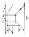
- FIG. 4is a timing chart of the operations of the stapler apparatus mounted with the staple cartridge according to the invention.
- FIG. 1is an external perspective view showing a section of part of the entire stapler apparatus, mainly comprising the staple cartridge 100 , the cartridge holder 200 and the stapler unit 300 .
- the stapler unit 300comprises the unit frame 310 , the electric drive unit, not shown in the figures, the staple head unit 330 , the actuating lever 340 , the anvil unit 350 , the clincher unit 360 , the interlock lever 370 , the anvil spring 380 , the paper thickness absorbing spring 390 , the clincher spring 400 and the manual drive plate 500 .
- the unit frame 310is sheet metal pressed formed into a sectional U-shape comprising sides established left, right and a bottom. It internally holds the electric drive unit, thereabove the holder guide 301 , which is shown in FIG. 2 and the staple head unit 330 in the leading edge and properly supports other units on the outside side walls thereof.
- the electric drive unitwhich is not shown in the figures, is composed of a direct current motor that is the stapler drive source, the gear train that decelerates the rotation of the motor to a determined rotating speed and the transmission cams that are decelerated to the determined speed and rotate.
- Each transmissiondrives the staple head unit 330 and the anvil unit 350 via the actuating lever 340 and the interlock lever 370 and by driving the clincher unit 360 it controls the series of operations of the stapler.
- the staple head unit 330comprises the sheet loading table 331 , the driver 332 , the former 333 , the sheath 334 and the bending block 335 .
- the staple head unit 330starts the upward direction displacement of the driver 332 pressed formed with a leaf spring material by the driver drive cam pin disposed on the last level of the electric drive unit.
- Displacement of the driver 332abuts the former abutting piece 332 a on the driver 332 against the former 333 .
- the driver 332 and former 333follow a stepped surface, not shown in the figures, formed on the sheath 334 upward to a position where that abutment is released.
- the former 333bends into a U-shape staples drawn to the staple bending position of the bending block bending block 335 and holds to guide U-shaped staples on the sides of the former 333 thereof to enable driving. Note that the position where the staple is bent by the former 333 corresponds to the staple driving position below.
- the staple driving unit 332 b positioned at the leading edge of the driver 332displaces the bending block 335 to the front from the region of movement of the driver 332 and retracts.
- the staple driving unit 332 b of the driver 332 displaced further upwardseparates from the adhesive staples that have been bent and are adhering to the next staple by adhesive tape. Formed and separated staples are driven by the binding media.
- the actuating lever 340has arms extending left and right along the side surfaces of the anvil unit 350 . While nipping in the unit frame 310 , they are supported by the interlocking pivot shaft 331 disposed on the anvil unit 350 sides.
- the paper thickness absorbing springs 390are stretched between the anvil unit 350 in a central location on the left and right arms of the actuating lever 340 . These springs 390 constantly urge in the counterclockwise direction around the interlocking pivot shaft 331 to contact with the stopper 351 formed on the anvil unit 350 .
- the notch 341comprising an edge to abut with the anvil drive lever, which is not shown in the figures, driven to displacement by the electric drive unit is formed on the leading edge of the arm positioned on the other edge of the left and right arms.
- the anvil drive leverswings it clockwise around the interlocking pivot shaft 331 which is pressed and urged downward.
- the anvil unit 350is constantly rotatingly urged in the clockwise direction by the anvil spring 380 around the pivot shaft 312 .
- the anvil head 353 on the other sidefollows the rocking of the actuating lever 340 and rocks counter-clockwise resisting the urging force of the anvil spring 380 to nip and support the binding media at a position that corresponds to the thickness thereof.
- the actuating lever 340continues acting alone in resistance to the resilient force of the paper thickness absorbing springs 390 because the anvil unit 350 is locked in that nipping position.
- the clincher unit 360that has the left and right paired clinchers 354 for bending the leading edges of staples that have penetrated the binding media driven from below the binding media, is disposed to follow.
- the clincher unit 360comprises the clincher lever 361 and is supported by the pivot shaft 312 on the unit frame 310 which is also the pivot for the anvil rocking pivot 352 on the anvil unit 350 .
- To the leading edge of the clincher unit 360is mounted the clincher head 362 that bends staples that have been driven and rocks the clincher 354 mounted to the anvil head 353 on the anvil unit 350 .
- the clincher head 362is press formed using a steel plate for a spring with a thickness of 1.5 mm while the clincher lever 361 is formed using a plated steel plate of a thickness of 2.0 mm, to absorb the difference in pressing stroke of the clincher 354 .
- the interlock lever 370follows the rocking of the anvil unit 350 via the clincher spring 400 to rock the clincher unit 360 and is disposed to continue rotating with the rocking of the clincher drive lever, not shown in the drawings, while the anvil unit 350 nips and stops the binding media and after the anvil unit 350 stops at the nipping position that corresponds to the thickness of the binding media, it continues rotating to bend the staples.
- the manual drive plate 500is for resetting stapling defects by manually operating the stapler when a staple is not properly driven into the binding media and the defective staple prevents the stapler apparatus from operating and thus causes a stapling problem.
- the manual drive plate 500is mated to the rotating shaft extending to the back side of the output shaft of the direct current motor of the electric drive unit, which is not shown.
- FIG. 2is an exploded perspective view showing the cartridge holder 200 and staple cartridge 100 that are mounted on the stapler unit 300 in FIG. 1 pulled out.
- the cartridge lock lever 600which abuts the staple cartridge 100 and urgingly supports in the mounting direction is manually pressed downward to release the abutting. Then, the staple cartridge 100 is pulled from the cartridge holder 200 .
- the cartridge holder 200is pulled from the stapler unit 300 .
- the staple cartridge 100is composed of a semi-transparent plastic case and comprises the storage unit 102 that stores the staple band material 101 into which sheets of a plurality of straight staples linked into a band are wrapped into a roll, and the pull-out guide 103 for pulling out the staple band material 101 .
- the pull-out guide 103is mounted to the cartridge holder 200 and is equipped with the opening 104 of the guide surface on the leading top side being widely cut away to abut the staple feed means 202 on the cartridge holder 200 , the back-feed stopper pawl 105 to arrest so that the staple band material 101 pulled out from the storage unit 102 does not return back into the storage unit 102 , and the leading edge stopper 106 that restricts the leading edge of the staple band material 101 that has been pulled out and that positions the leading edge thereof at the binding position while mounted to the stapler unit 300 .
- the feed pawl advancing protrusion 107that protrudes into the guide surface on the top-side of the leading edge formed on the opening 104 on the pull-out guide 103 and advances the staple feed means 202 when mounting to the cartridge holder 200 to press the leading edge of staples in the staple band material 01 to the edge stopper 106 .
- both sides of the staple cartridge 100are equipped the guide protrusion 108 guided when mounting to the cartridge holder 200 and the stopper pawl 109 stopped when mounting to the cartridge holder cartridge holder 200 .
- the cartridge holder 200is composed of the holder unit 201 , the staple feed means 202 , the magnet 203 , the guide plate 204 comprising a non-magnetic body, the opening 205 , the guide 206 , the abutting hole 207 and the auxiliary table 208 .
- the holder unit 201is formed of a plastic material to cover the front half of the staple cartridge 100 .
- the staple feed means 202is rockingly supported on the holder unit 201 and is constantly urged to the staple pull-out direction by a leaf spring, which is not shown in the figures. It is interlocked to the nipping action of the binding means by the anvil unit 350 and charged. It comprises a feed pawl for pressing the staple sheet surface of the staple band material 101 with the recovery action caused by the release of the charge to advance the staple band material 101 .
- the magnet 203 and the guide plate 204faces the staple to be driven at the binding position when mounted to the stapler unit 300 and the magnetic attraction of the magnet attracts mis-driven staples to discharge them outside from the stapler unit 300 .
- the opening 205is for setting the leading edge of the stopper 106 on the staple cartridge 100 and the leading edge of the staple to protrude and be set at the binding position.
- the guide 206is for guiding the guide protrusion 108 on the staple cartridge 100 and is composed of a cut-out groove and a bottom surface.
- the abutting hole 207abuts the stopper pawl 108 on the staple cartridge 100 and it is one of the supplementary stopping means on the staple cartridge 100 until the staple cartridge 100 is locked by the cartridge lock lever 600 .
- the supplementary table 208acts as the loading table where the binding media is loaded along with the table 331 on the staple head unit 330 , as shown in FIG. 1 , when mounted to the stapler unit 300 .
- FIG. 3shows the staple cartridge 100 disassembled.
- the cover 100 bmates with the urging means 701 on the support shaft 109 b on the cover 100 b .
- the staple band memberis mated to the cover 100 b from above.
- pressing the urging means 702 to the shaft 109 a on the other cover 100 ait mates and covers the regulating means 700 a .
- assemblyis completed by inserting the return stopper pawl 105 to the staple band member 101 .
- the surfaces of the regulating means of 700 a and 700 b facing the stacked surfaces 101 a and 101 b on the staple band material 101can hold to a degree where it does not easily move even if there is a vibration, the rough surface considering the urging force of the urging means 701 and 702 .
- the forces to regulate the unraveling while in contact with the stacked surface of the staple band material 101do not act together, however when there is vibration, they act mutually to not displace the relative positions by the vibrations to the staple band material 101 .
- the regulating means 700 a and 700 bare the regulating plates rotatingly supported to the staple storage portion 102 .
- the surfaces of the regulating means 700 a and 700 b facing the staple storage portion 102slide easily and follow the rotation of the roller portion when drawing out the staple band member 101 to enable it to rotate.
- their surfacescan be a metal plate such as aluminum that is thin and planar, the catching side portion of the aforementioned VELCRO, hook and loop fasteners being affixed to the metal plate.
- the regulating surface of the regulating means 700 a and 700 bcan be pointed needles such as those used in flower arrangement, rather than the catching part of the aforementioned VELCRO hook and loop fasteners. Furthermore, it is possible to regulate the displacement by the vibration of the staple band with the reverse action caused by the elastic deformation when elastically deforming by the needle tips of the staple band material that vibrate.
- FIG. 4is a timing charge to illustrate the operation of each of the driver, former, anvil and clincher units' processes.
- the horizontal axisindicates the angle of rotation of the drive cam that drives each unit and the vertical axis shows the amount of displacement of the levers for each unit. The following generally describes the series of actions according to FIG. 1 .
- a staple execution instruction signalis output to the stapler apparatus from an outside source.
- the instruction signalstarts the rotation of the direct current motor in the electric drive unit, which is not shown in the drawings, first pushing the actuating lever 340 in the downward direction by the anvil drive cam, which is not shown in the drawings, resisting the anvil spring 380 .
- the anvil unit 350moves downward to start nipping the binding media.
- the clincher unit 360 interlocked by the interlock lever 370 and the clincher spring 400follows the anvil unit 350 .
- the anvil unit 360maintains a displaced state to the position equivalent to the position A 3 by applying an over-stroke to the position A 2 to enable the secure nipping even if there are 0 pages of binding media, in consideration of variations in parts and their assembly, to complete the nipping operation of the binding media using the anvil unit 360 .
- the driver drive cam CA 40shown in FIG. 4 displaces the driver 332 , which is not shown in the drawing, upward, and the former 333 following this displacement is pressed upward.
- the driver 332begins moving from the position D 1 when the clincher unit 360 is beyond the position A 1 , at position D 2 , the former 333 presses the staple drawing to the driving position and starts forming the staple into a U-shape.
- both leading edges of bent staples formed into that shape against the sides of the bending block 335 to guide itboth leading edges of the staple are secured front, back left and right by the non-magnetic materials of the guide plate 204 walls composed of the former 333 , the bending block 335 and the cartridge holder 200 .
- the leading edges that touch the formed staple of the driver 332are pressed into the oblique surfaces of the bending block 335 .
- the leading edge portion of the driver 332touches the formed staple at the position D 3 with the bending block 335 retracted from the area of movement of the leading edge of the driver 332 .
- the former 333is released from abutting with the driver 332 at the position D 6 just prior to the leading edge of the former 333 touching the surface of the sheets in the binding media and the former 333 stops and the former guides the bend staple driven by the driver 332 .
- the formed stapleis driven by the driver 332 , and after the formed staple crown touches the surface of the sheets in the binding media at the position D 7 , the driver 332 is further driven by the driver drive cam at the position D 8 , but because the driver 332 cannot press the formed staples in, the driver 332 comprising a leaf spring, itself is elastically deformed the amount of the over-stroke to absorb the difference of the mounting position to securely drive the formed staple.
- the clincher unit 360is rocked by the clincher drive unit 602 pressed downward by the clincher drive cam CA 10 shown in FIG. 11 from position C 1 immediately after the position D 8 where the formed staple is driven by the driver 332 , pressing the clincher 354 to complete the clinching operation at the position C 2 by bending the leading edges of the staples that have penetrated the binding media.
- the recover operationis started for the driver 332 at the position D 11 .
- the former 333 partwayis re-interlocked and returned to the position D 0 which is equivalent to the initial position passing through the positions of D 12 and D 13 .
- the anvil unit 350 recovery operationis started slightly delayed to the recovery operation of the driver 332 and is returned to the position A 7 which is equivalent to the initial position passing through the position A 6 .
- anvil unit 360 recovery operationis started slightly delayed to the recovery operation of the driver 350 and is returned to the position C 4 which is equivalent to the initial position to complete the series of the staple operation.
Landscapes
- Engineering & Computer Science (AREA)
- Mechanical Engineering (AREA)
- Life Sciences & Earth Sciences (AREA)
- Forests & Forestry (AREA)
- Portable Nailing Machines And Staplers (AREA)
- Dovetailed Work, And Nailing Machines And Stapling Machines For Wood (AREA)
- Folding Of Thin Sheet-Like Materials, Special Discharging Devices, And Others (AREA)
Abstract
Description
- 100 Staple cartridge
- 101 Staple band material
- 101a,101bStack surfaces
- 102 Staple storage portion
- 200 Cartridge holder
- 300 Stapler unit
- 700 Regulating means (Regulating plate)
Claims (22)
Applications Claiming Priority (3)
| Application Number | Priority Date | Filing Date | Title |
|---|---|---|---|
| JP2000-402785 | 2000-12-28 | ||
| JP2000402785AJP2002200575A (en) | 2000-12-28 | 2000-12-28 | Staple cartridge and stapler provided with the same |
| PCT/IB2001/002625WO2002053329A2 (en) | 2000-12-28 | 2001-12-21 | Stapler cartridge and stapler apparatus comprising the same |
Publications (2)
| Publication Number | Publication Date |
|---|---|
| US20040217145A1 US20040217145A1 (en) | 2004-11-04 |
| US6913181B2true US6913181B2 (en) | 2005-07-05 |
Family
ID=18867018
Family Applications (1)
| Application Number | Title | Priority Date | Filing Date |
|---|---|---|---|
| US10/450,062Expired - Fee RelatedUS6913181B2 (en) | 2000-12-28 | 2001-12-21 | Stapler cartridge and stapler apparatus comprising the same |
Country Status (3)
| Country | Link |
|---|---|
| US (1) | US6913181B2 (en) |
| JP (1) | JP2002200575A (en) |
| WO (1) | WO2002053329A2 (en) |
Cited By (27)
| Publication number | Priority date | Publication date | Assignee | Title |
|---|---|---|---|---|
| US20060054653A1 (en)* | 2002-10-09 | 2006-03-16 | Takao Hasegawa | Staple case |
| US20060255087A1 (en)* | 2003-02-06 | 2006-11-16 | Olle Straat | Releasable staple magazine with a releasable staple forming arrangement |
| US20070009705A1 (en)* | 2003-08-29 | 2007-01-11 | Max Kabushiki Kaisha | Staple refill |
| US20070125824A1 (en)* | 2004-12-03 | 2007-06-07 | Wojcicki Andrzej R | Magazine for wired-collated fasteners with automatic loading |
| US20070170223A1 (en)* | 2006-01-24 | 2007-07-26 | Rick Lin | Nail Magazine for a Nailer |
| US20080128466A1 (en)* | 2003-12-04 | 2008-06-05 | Takao Hasegawa | Stapling Apparatus |
| US20090114697A1 (en)* | 2004-12-03 | 2009-05-07 | Black & Decker Inc. | Magazine for wired-collated fasteners with automatic loading |
| US20090166393A1 (en)* | 2007-02-01 | 2009-07-02 | Black & Decker Inc. | Multistage solenoid fastening device |
| US20100176179A1 (en)* | 2006-08-11 | 2010-07-15 | Max Co., Ltd. | Staple strip and staple cartridge |
| US10448949B2 (en) | 2015-08-06 | 2019-10-22 | Applied Medical Resources Corporation | Surgical stapler having locking articulation joint |
| US10517597B2 (en) | 2016-04-12 | 2019-12-31 | Applied Medical Resources Corporation | Surgical stapler having articulation mechanism |
| US10595866B2 (en) | 2013-03-15 | 2020-03-24 | Applied Medical Resources Corporation | Surgical stapler handle assembly having actuation mechanism with longitudinally rotatable shaft |
| US10610225B2 (en) | 2016-04-12 | 2020-04-07 | Applied Medical Resources Corporation | Surgical stapler having a powered handle |
| US10792038B2 (en) | 2014-09-15 | 2020-10-06 | Applied Medical Resources Corporation | Surgical stapler with self-adjusting staple height |
| US10888326B2 (en) | 2013-03-15 | 2021-01-12 | Applied Medical Resources Corporation | Surgical stapler with expandable jaw |
| US10905420B2 (en) | 2016-04-12 | 2021-02-02 | Applied Medical Resources Corporation | Reload shaft assembly for surgical stapler |
| US11020117B2 (en) | 2014-06-11 | 2021-06-01 | Applied Medical Resources Corporation | Surgical stapler with circumferential firing |
| US11051812B2 (en) | 2013-03-14 | 2021-07-06 | Applied Medical Resources Corporation | Surgical stapler with partial pockets |
| US11064999B2 (en) | 2018-02-27 | 2021-07-20 | Applied Medical Resources Corporation | Surgical stapler having a powered handle |
| US11311293B2 (en) | 2019-02-27 | 2022-04-26 | Applied Medical Resources Corporation | Surgical stapling instrument having a two-position lockout mechanism |
| US11375999B2 (en) | 2006-05-19 | 2022-07-05 | Applied Medical Resources Corporation | Surgical stapler with firing lock mechanism |
| US11717293B2 (en) | 2019-03-29 | 2023-08-08 | Applied Medical Resources Corporation | Reload cover for surgical stapling system |
| US11730475B2 (en) | 2020-10-29 | 2023-08-22 | Applied Medical Resources Corporation | Surgical stapler having a powered handle |
| US11771428B2 (en) | 2020-10-29 | 2023-10-03 | Applied Medical Resources Corporation | Actuation shaft retention mechanism for surgical stapler |
| US11963711B2 (en) | 2019-12-31 | 2024-04-23 | Applied Medical Resources Corporation | Electrosurgical system with tissue and maximum current identification |
| US12048431B2 (en) | 2020-10-29 | 2024-07-30 | Applied Medical Resources Corporation | Material combinations and processing methods for a surgical instrument |
| US12279767B2 (en) | 2021-01-14 | 2025-04-22 | Applied Medical Resources Corporation | Surgical stapler having shaft recognition mechanism |
Families Citing this family (3)
| Publication number | Priority date | Publication date | Assignee | Title |
|---|---|---|---|---|
| JP4154987B2 (en)* | 2002-10-09 | 2008-09-24 | マックス株式会社 | Staple case |
| EP2196288B1 (en) | 2003-02-07 | 2011-11-23 | MAX Kabushiki Kaisha | Staple Refill, Stapler |
| JP5181805B2 (en)* | 2008-04-25 | 2013-04-10 | マックス株式会社 | Staple cartridge and stapler in stapler |
Citations (16)
| Publication number | Priority date | Publication date | Assignee | Title |
|---|---|---|---|---|
| US3009618A (en)* | 1956-01-27 | 1961-11-21 | Inv S Man Corp | Staple element cartridge |
| US3009156A (en)* | 1956-05-18 | 1961-11-21 | Inv S Man Corp | Industrial tacker |
| US3330462A (en)* | 1966-05-09 | 1967-07-11 | Bostitch Inc | Fastener driving apparatus |
| US3602414A (en)* | 1969-01-14 | 1971-08-31 | Swingline Inc | Dispenser for belt-type staples |
| US4518109A (en)* | 1983-02-02 | 1985-05-21 | Tachikawa Pin Seisakujo Co., Ltd. | Magazine device of air nailer |
| US4585154A (en)* | 1984-03-26 | 1986-04-29 | Bostitch Division Of Textron Inc. | Fastener driving tool with adjustable three-part magazine canister assembly |
| US4770334A (en) | 1985-09-24 | 1988-09-13 | Canon Kabushiki Kaisha | Stapler apparatus |
| US4844636A (en)* | 1987-04-28 | 1989-07-04 | Kroy Inc. | Unitary tape-ribbon cartridge for lettering system |
| US4913332A (en) | 1989-01-23 | 1990-04-03 | Swingline Inc. | Sheath release device for stapler |
| US5121868A (en) | 1991-06-26 | 1992-06-16 | Swingline Inc. | Stapler mechanism including jam clearing device |
| US5273199A (en) | 1990-03-07 | 1993-12-28 | Xerox Corporation | Staple cartridge |
| US5683024A (en)* | 1993-05-13 | 1997-11-04 | Stanley-Bostitch, Inc. | Fastener driving device particularly suited for use as a roofing nailer |
| US5794833A (en)* | 1992-04-16 | 1998-08-18 | Isaberg Ab | Cassette for use in a stapler |
| US6048118A (en)* | 1998-08-07 | 2000-04-11 | Axiohm Transaction Solutions, Inc. | Compact ribbon cassette with integral friction plate |
| US6050471A (en) | 1996-10-23 | 2000-04-18 | Max Co., Ltd. | Electric stapler |
| US6152346A (en)* | 1999-05-24 | 2000-11-28 | Illinois Tool Work Inc. | Adjustable magazines for nail tools and methods therefor |
- 2000
- 2000-12-28JPJP2000402785Apatent/JP2002200575A/enactivePending
- 2001
- 2001-12-21USUS10/450,062patent/US6913181B2/ennot_activeExpired - Fee Related
- 2001-12-21WOPCT/IB2001/002625patent/WO2002053329A2/enactiveApplication Filing
Patent Citations (16)
| Publication number | Priority date | Publication date | Assignee | Title |
|---|---|---|---|---|
| US3009618A (en)* | 1956-01-27 | 1961-11-21 | Inv S Man Corp | Staple element cartridge |
| US3009156A (en)* | 1956-05-18 | 1961-11-21 | Inv S Man Corp | Industrial tacker |
| US3330462A (en)* | 1966-05-09 | 1967-07-11 | Bostitch Inc | Fastener driving apparatus |
| US3602414A (en)* | 1969-01-14 | 1971-08-31 | Swingline Inc | Dispenser for belt-type staples |
| US4518109A (en)* | 1983-02-02 | 1985-05-21 | Tachikawa Pin Seisakujo Co., Ltd. | Magazine device of air nailer |
| US4585154A (en)* | 1984-03-26 | 1986-04-29 | Bostitch Division Of Textron Inc. | Fastener driving tool with adjustable three-part magazine canister assembly |
| US4770334A (en) | 1985-09-24 | 1988-09-13 | Canon Kabushiki Kaisha | Stapler apparatus |
| US4844636A (en)* | 1987-04-28 | 1989-07-04 | Kroy Inc. | Unitary tape-ribbon cartridge for lettering system |
| US4913332A (en) | 1989-01-23 | 1990-04-03 | Swingline Inc. | Sheath release device for stapler |
| US5273199A (en) | 1990-03-07 | 1993-12-28 | Xerox Corporation | Staple cartridge |
| US5121868A (en) | 1991-06-26 | 1992-06-16 | Swingline Inc. | Stapler mechanism including jam clearing device |
| US5794833A (en)* | 1992-04-16 | 1998-08-18 | Isaberg Ab | Cassette for use in a stapler |
| US5683024A (en)* | 1993-05-13 | 1997-11-04 | Stanley-Bostitch, Inc. | Fastener driving device particularly suited for use as a roofing nailer |
| US6050471A (en) | 1996-10-23 | 2000-04-18 | Max Co., Ltd. | Electric stapler |
| US6048118A (en)* | 1998-08-07 | 2000-04-11 | Axiohm Transaction Solutions, Inc. | Compact ribbon cassette with integral friction plate |
| US6152346A (en)* | 1999-05-24 | 2000-11-28 | Illinois Tool Work Inc. | Adjustable magazines for nail tools and methods therefor |
Cited By (64)
| Publication number | Priority date | Publication date | Assignee | Title |
|---|---|---|---|---|
| US20060054653A1 (en)* | 2002-10-09 | 2006-03-16 | Takao Hasegawa | Staple case |
| US7497329B2 (en)* | 2002-10-09 | 2009-03-03 | Max Co., Ltd. | Staple case |
| US20060255087A1 (en)* | 2003-02-06 | 2006-11-16 | Olle Straat | Releasable staple magazine with a releasable staple forming arrangement |
| US7469810B2 (en)* | 2003-02-06 | 2008-12-30 | Isaberg Rapid Ab | Releasable staple magazine with a releasable staple forming arrangement |
| US20070009705A1 (en)* | 2003-08-29 | 2007-01-11 | Max Kabushiki Kaisha | Staple refill |
| US7513405B2 (en)* | 2003-08-29 | 2009-04-07 | Max Kabushiki Kaisha | Staple refill with backward movement preventing member |
| US20080128466A1 (en)* | 2003-12-04 | 2008-06-05 | Takao Hasegawa | Stapling Apparatus |
| US7866521B2 (en) | 2004-12-03 | 2011-01-11 | Black & Decker Inc. | Magazine for wired-collated fasteners with automatic loading |
| US20070125824A1 (en)* | 2004-12-03 | 2007-06-07 | Wojcicki Andrzej R | Magazine for wired-collated fasteners with automatic loading |
| US7455207B2 (en)* | 2004-12-03 | 2008-11-25 | Black & Decker Inc. | Magazine for wired-collated fasteners with automatic loading |
| US20090114697A1 (en)* | 2004-12-03 | 2009-05-07 | Black & Decker Inc. | Magazine for wired-collated fasteners with automatic loading |
| US20070170223A1 (en)* | 2006-01-24 | 2007-07-26 | Rick Lin | Nail Magazine for a Nailer |
| US11375999B2 (en) | 2006-05-19 | 2022-07-05 | Applied Medical Resources Corporation | Surgical stapler with firing lock mechanism |
| US20100176179A1 (en)* | 2006-08-11 | 2010-07-15 | Max Co., Ltd. | Staple strip and staple cartridge |
| US9261125B2 (en) | 2006-08-11 | 2016-02-16 | Max Co., Ltd. | Staple strip and staple cartridge |
| US9382934B2 (en)* | 2006-08-11 | 2016-07-05 | Max Co. Ltd. | Staple strip and staple cartridge |
| US7665540B2 (en) | 2007-02-01 | 2010-02-23 | Black & Decker Inc. | Multistage solenoid fastening device |
| US20090166393A1 (en)* | 2007-02-01 | 2009-07-02 | Black & Decker Inc. | Multistage solenoid fastening device |
| US7913890B2 (en) | 2007-02-01 | 2011-03-29 | Black & Decker Inc. | Multistage solenoid fastening device |
| US11051812B2 (en) | 2013-03-14 | 2021-07-06 | Applied Medical Resources Corporation | Surgical stapler with partial pockets |
| US11812963B2 (en) | 2013-03-14 | 2023-11-14 | Applied Medical Resources Corporation | Surgical stapler with partial pockets |
| US12144504B2 (en) | 2013-03-15 | 2024-11-19 | Applied Medical Resources Corporation | Surgical stapler with expandable jaw |
| US11607220B2 (en) | 2013-03-15 | 2023-03-21 | Applied Medical Resources Corporation | Surgical stapler with expandable jaw |
| US10888326B2 (en) | 2013-03-15 | 2021-01-12 | Applied Medical Resources Corporation | Surgical stapler with expandable jaw |
| US11389163B2 (en) | 2013-03-15 | 2022-07-19 | Applied Medical Resources Corporation | Surgical stapler with expandable jaw |
| US10912565B2 (en) | 2013-03-15 | 2021-02-09 | Applied Medical Resources Corporation | Surgical stapler handle assembly having actuation mechanism with longitudinally rotatable shaft |
| US10595866B2 (en) | 2013-03-15 | 2020-03-24 | Applied Medical Resources Corporation | Surgical stapler handle assembly having actuation mechanism with longitudinally rotatable shaft |
| US11844491B2 (en) | 2013-03-15 | 2023-12-19 | Applied Medical Resources Corporation | Surgical stapler handle assembly having actuation mechanism with longitudinally rotatable shaft |
| US12137907B2 (en) | 2013-03-15 | 2024-11-12 | Applied Medical Resources Corporation | Surgical stapler handle assembly having actuation mechanism with longitudinally rotatable shaft |
| US11529141B2 (en) | 2013-03-15 | 2022-12-20 | Applied Medical Resources Corporation | Surgical stapler handle assembly having actuation mechanism with longitudinally rotatable shaft |
| US11666336B2 (en) | 2014-06-11 | 2023-06-06 | Applied Medical Resources Corporation | Surgical stapler with circumferential firing |
| US11020117B2 (en) | 2014-06-11 | 2021-06-01 | Applied Medical Resources Corporation | Surgical stapler with circumferential firing |
| US12161336B2 (en) | 2014-06-11 | 2024-12-10 | Applied Medical Resources Corporation | Surgical stapler with circumferential firing |
| US10792038B2 (en) | 2014-09-15 | 2020-10-06 | Applied Medical Resources Corporation | Surgical stapler with self-adjusting staple height |
| US12011169B2 (en) | 2014-09-15 | 2024-06-18 | Applied Medical Resources Corporation | Surgical stapler with self-adjusting staple height |
| US11523825B2 (en) | 2014-09-15 | 2022-12-13 | Applied Medical Resources Corporation | Surgical stapler with self-adjusting staple height |
| US11357504B2 (en) | 2015-08-06 | 2022-06-14 | Applied Medical Resources Corporation | Surgical stapler having locking articulation joint |
| US10448949B2 (en) | 2015-08-06 | 2019-10-22 | Applied Medical Resources Corporation | Surgical stapler having locking articulation joint |
| US11826046B2 (en) | 2016-04-12 | 2023-11-28 | Applied Medical Resources Corporation | Surgical stapler having a powered handle |
| US11925351B2 (en) | 2016-04-12 | 2024-03-12 | Applied Medical Resources Corporation | Surgical stapler having articulation mechanism |
| US10517597B2 (en) | 2016-04-12 | 2019-12-31 | Applied Medical Resources Corporation | Surgical stapler having articulation mechanism |
| US12414769B2 (en) | 2016-04-12 | 2025-09-16 | Applied Medical Resources Corporation | Reload shaft assembly for surgical stapler |
| US10610225B2 (en) | 2016-04-12 | 2020-04-07 | Applied Medical Resources Corporation | Surgical stapler having a powered handle |
| US12324582B2 (en) | 2016-04-12 | 2025-06-10 | Applied Medical Resources Corporation | Surgical stapler having a powered handle |
| US11272933B2 (en) | 2016-04-12 | 2022-03-15 | Applied Medical Resources Corporation | Surgical stapler having articulation mechanism |
| US11272934B2 (en) | 2016-04-12 | 2022-03-15 | Applied Medical Resources Corporation | Surgical stapler having a powered handle |
| US11684366B2 (en) | 2016-04-12 | 2023-06-27 | Applied Medical Resources Corporation | Reload shaft assembly for surgical stapler |
| US10905420B2 (en) | 2016-04-12 | 2021-02-02 | Applied Medical Resources Corporation | Reload shaft assembly for surgical stapler |
| US11064999B2 (en) | 2018-02-27 | 2021-07-20 | Applied Medical Resources Corporation | Surgical stapler having a powered handle |
| US11937815B2 (en) | 2018-02-27 | 2024-03-26 | Applied Medical Resources Corporation | Surgical stapler having a powered handle |
| US11311293B2 (en) | 2019-02-27 | 2022-04-26 | Applied Medical Resources Corporation | Surgical stapling instrument having a two-position lockout mechanism |
| US11751871B2 (en) | 2019-02-27 | 2023-09-12 | Applied Medical Resources Corporation | Surgical stapling instrument having a two-position lockout mechanism |
| US12213667B2 (en) | 2019-02-27 | 2025-02-04 | Applied Medical Resources Corporation | Surgical stapling instrument having a two-position lockout mechanism |
| US12285167B2 (en) | 2019-03-29 | 2025-04-29 | Applied Medical Resources Corporation | Reload cover for surgical stapling system |
| US11717293B2 (en) | 2019-03-29 | 2023-08-08 | Applied Medical Resources Corporation | Reload cover for surgical stapling system |
| US11963711B2 (en) | 2019-12-31 | 2024-04-23 | Applied Medical Resources Corporation | Electrosurgical system with tissue and maximum current identification |
| US12402936B2 (en) | 2019-12-31 | 2025-09-02 | Applied Medical Resources Corporation | Electrosurgical system with tissue and maximum current identification |
| US12193668B2 (en) | 2020-10-29 | 2025-01-14 | Applied Medical Resources Corporation | Surgical stapler having a powered handle |
| US12161330B2 (en) | 2020-10-29 | 2024-12-10 | Applied Medical Resources Corporation | Actuation shaft retention mechanism for surgical stapler |
| US12048431B2 (en) | 2020-10-29 | 2024-07-30 | Applied Medical Resources Corporation | Material combinations and processing methods for a surgical instrument |
| US11771428B2 (en) | 2020-10-29 | 2023-10-03 | Applied Medical Resources Corporation | Actuation shaft retention mechanism for surgical stapler |
| US12357304B2 (en) | 2020-10-29 | 2025-07-15 | Applied Medical Resources Corporation | Material combinations and processing methods for a surgical instrument |
| US11730475B2 (en) | 2020-10-29 | 2023-08-22 | Applied Medical Resources Corporation | Surgical stapler having a powered handle |
| US12279767B2 (en) | 2021-01-14 | 2025-04-22 | Applied Medical Resources Corporation | Surgical stapler having shaft recognition mechanism |
Also Published As
| Publication number | Publication date |
|---|---|
| WO2002053329A2 (en) | 2002-07-11 |
| US20040217145A1 (en) | 2004-11-04 |
| WO2002053329A3 (en) | 2008-07-10 |
| JP2002200575A (en) | 2002-07-16 |
Similar Documents
| Publication | Publication Date | Title |
|---|---|---|
| US6913181B2 (en) | Stapler cartridge and stapler apparatus comprising the same | |
| US8226077B2 (en) | Sheet processing apparatus and sheet processing method | |
| US7017789B2 (en) | Stapler cartridge and stapler apparatus comprising the same | |
| US6902094B2 (en) | Stapler apparatus | |
| US7014084B2 (en) | Stapling apparatus with interconnected feeding and clinching | |
| US7059506B2 (en) | Stapler apparatus | |
| JP3657174B2 (en) | Staple device | |
| US7036706B2 (en) | Stapler apparatus | |
| US6974068B2 (en) | Stapler device | |
| KR20050023303A (en) | Stapler and cartridge | |
| US6918524B1 (en) | Staple attracting member for attracting jammed staples | |
| US8511530B2 (en) | Stapler and staple | |
| JP3012334U (en) | Banknote binding device of banknote counting machine | |
| JPH058580A (en) | Sheet binding device | |
| JP2009113151A (en) | Stapler | |
| JP3674432B2 (en) | Electric stapler | |
| JPH0732089Y2 (en) | Tape feeding device for spine attachment device | |
| JPH0741547B2 (en) | Fixed magazine electric stapler | |
| JP3692878B2 (en) | Electric stapler | |
| WO2005115698A1 (en) | Clincher device for stapler | |
| JP2005014416A (en) | Staple feeding mechanism of electric stapler | |
| JP2009154245A (en) | Stapler | |
| JPH06336093A (en) | Staple needle removing device |
Legal Events
| Date | Code | Title | Description |
|---|---|---|---|
| AS | Assignment | Owner name:ACCO BRANDS, INC., ILLINOIS Free format text:ASSIGNMENT OF ASSIGNORS INTEREST;ASSIGNORS:MOCHIZUKI, NAOTO;SAJIKI, YOSUKE;REEL/FRAME:014642/0389 Effective date:20021029 Owner name:NISCA CORPORATION, JAPAN Free format text:ASSIGNMENT OF ASSIGNORS INTEREST;ASSIGNORS:MOCHIZUKI, NAOTO;SAJIKI, YOSUKE;REEL/FRAME:014642/0389 Effective date:20021029 | |
| AS | Assignment | Owner name:CITICORP NORTH AMERICA, AS ADMINISTRATIVE AGENT, I Free format text:PATENT SECURITY AGREEMENT;ASSIGNORS:ACCO BRANDS CORPORATION, A DELAWARE CORPORATION;ACCO BRANDS USA LLC, A DELAWARE LIMITED LIABILITY COMPANY BOONE INTERNATIONAL, INC., A CALIFORNIA CORPORATION GENERAL BINDING CORPORATION, A DELAWARE CORPORATION;BOONE INTERNATIONAL, INC., A CALIFORNIA CORPORATION;AND OTHERS;REEL/FRAME:016914/0813 Effective date:20050817 | |
| AS | Assignment | Owner name:ACCO BRANDS USA LLC, ILLINOIS Free format text:CHANGE OF NAME;ASSIGNOR:ACCO BRANDS, INC.;REEL/FRAME:016674/0785 Effective date:20050802 | |
| REMI | Maintenance fee reminder mailed | ||
| LAPS | Lapse for failure to pay maintenance fees | ||
| STCH | Information on status: patent discontinuation | Free format text:PATENT EXPIRED DUE TO NONPAYMENT OF MAINTENANCE FEES UNDER 37 CFR 1.362 | |
| FP | Lapsed due to failure to pay maintenance fee | Effective date:20090705 |