US6913088B2 - Hammer drill and /or percussion hammer with no-load operation control that depends on application pressure - Google Patents
Hammer drill and /or percussion hammer with no-load operation control that depends on application pressureDownload PDFInfo
- Publication number
- US6913088B2 US6913088B2US10/485,673US48567304AUS6913088B2US 6913088 B2US6913088 B2US 6913088B2US 48567304 AUS48567304 AUS 48567304AUS 6913088 B2US6913088 B2US 6913088B2
- Authority
- US
- United States
- Prior art keywords
- hammer
- percussion
- drive piston
- handle
- housing
- Prior art date
- Legal status (The legal status is an assumption and is not a legal conclusion. Google has not performed a legal analysis and makes no representation as to the accuracy of the status listed.)
- Expired - Fee Related
Links
- 238000009527percussionMethods0.000titleclaimsabstractdescription95
- 230000007246mechanismEffects0.000claimsabstractdescription49
- 239000011796hollow space materialSubstances0.000claimsdescription31
- 238000006073displacement reactionMethods0.000claimsdescription13
- 230000009471actionEffects0.000claimsdescription11
- 230000001419dependent effectEffects0.000claimsdescription10
- 238000010276constructionMethods0.000claimsdescription5
- 238000005259measurementMethods0.000claimsdescription4
- 238000011156evaluationMethods0.000claimsdescription3
- 238000001514detection methodMethods0.000claims7
- 230000033001locomotionEffects0.000description15
- 239000004575stoneSubstances0.000description12
- 230000008859changeEffects0.000description6
- 230000000694effectsEffects0.000description6
- 238000013461designMethods0.000description5
- 230000009191jumpingEffects0.000description3
- 239000000463materialSubstances0.000description3
- 238000011161developmentMethods0.000description2
- 230000018109developmental processEffects0.000description2
- 238000000034methodMethods0.000description2
- 230000000149penetrating effectEffects0.000description2
- 230000007704transitionEffects0.000description2
- 238000009423ventilationMethods0.000description2
- 230000015572biosynthetic processEffects0.000description1
- 230000008878couplingEffects0.000description1
- 238000010168coupling processMethods0.000description1
- 238000005859coupling reactionMethods0.000description1
- 238000013016dampingMethods0.000description1
- 230000000977initiatory effectEffects0.000description1
- 230000000116mitigating effectEffects0.000description1
- 238000012986modificationMethods0.000description1
- 230000004048modificationEffects0.000description1
- 238000012545processingMethods0.000description1
- 230000009467reductionEffects0.000description1
- 238000000926separation methodMethods0.000description1
- 238000007493shaping processMethods0.000description1
- 230000000087stabilizing effectEffects0.000description1
Images


Classifications
- B—PERFORMING OPERATIONS; TRANSPORTING
- B25—HAND TOOLS; PORTABLE POWER-DRIVEN TOOLS; MANIPULATORS
- B25D—PERCUSSIVE TOOLS
- B25D11/00—Portable percussive tools with electromotor or other motor drive
- B25D11/005—Arrangements for adjusting the stroke of the impulse member or for stopping the impact action when the tool is lifted from the working surface
- B—PERFORMING OPERATIONS; TRANSPORTING
- B25—HAND TOOLS; PORTABLE POWER-DRIVEN TOOLS; MANIPULATORS
- B25D—PERCUSSIVE TOOLS
- B25D16/00—Portable percussive machines with superimposed rotation, the rotational movement of the output shaft of a motor being modified to generate axial impacts on the tool bit
- B—PERFORMING OPERATIONS; TRANSPORTING
- B25—HAND TOOLS; PORTABLE POWER-DRIVEN TOOLS; MANIPULATORS
- B25D—PERCUSSIVE TOOLS
- B25D17/00—Details of, or accessories for, portable power-driven percussive tools
- B25D17/04—Handles; Handle mountings
- B25D17/043—Handles resiliently mounted relative to the hammer housing
- B—PERFORMING OPERATIONS; TRANSPORTING
- B25—HAND TOOLS; PORTABLE POWER-DRIVEN TOOLS; MANIPULATORS
- B25D—PERCUSSIVE TOOLS
- B25D2211/00—Details of portable percussive tools with electromotor or other motor drive
- B25D2211/003—Crossed drill and motor spindles
- B—PERFORMING OPERATIONS; TRANSPORTING
- B25—HAND TOOLS; PORTABLE POWER-DRIVEN TOOLS; MANIPULATORS
- B25D—PERCUSSIVE TOOLS
- B25D2211/00—Details of portable percussive tools with electromotor or other motor drive
- B25D2211/06—Means for driving the impulse member
- B25D2211/068—Crank-actuated impulse-driving mechanisms
- B—PERFORMING OPERATIONS; TRANSPORTING
- B25—HAND TOOLS; PORTABLE POWER-DRIVEN TOOLS; MANIPULATORS
- B25D—PERCUSSIVE TOOLS
- B25D2250/00—General details of portable percussive tools; Components used in portable percussive tools
- B25D2250/035—Bleeding holes, e.g. in piston guide-sleeves
- B—PERFORMING OPERATIONS; TRANSPORTING
- B25—HAND TOOLS; PORTABLE POWER-DRIVEN TOOLS; MANIPULATORS
- B25D—PERCUSSIVE TOOLS
- B25D2250/00—General details of portable percussive tools; Components used in portable percussive tools
- B25D2250/131—Idling mode of tools
- B—PERFORMING OPERATIONS; TRANSPORTING
- B25—HAND TOOLS; PORTABLE POWER-DRIVEN TOOLS; MANIPULATORS
- B25D—PERCUSSIVE TOOLS
- B25D2250/00—General details of portable percussive tools; Components used in portable percussive tools
- B25D2250/221—Sensors
Definitions
- the present inventionrelates to a hammer drill and/or percussion hammer according to the preamble of patent claim 1 .
- a hammer drill and/or percussion hammerdesignated “hammer” in the following, standardly has an air pneumatic spring hammer mechanism in which a drive plunger is set into an oscillating back-and-forth movement by an electric motor, using a crankshaft or wobble shaft drive.
- a percussion pistonis situated before the drive piston, so that a hollow space, in which an air spring can form, is present between the drive piston and the percussion piston.
- the air springtransmits the back and forth movement of the drive piston to the percussion piston, and drives this percussion piston against the shaft of a tool or against an intermediately connected rivet header.
- Hammers of this sortare known in many different specific embodiments.
- control sleeve controllingthe relative movement of the tool to the hammer housing is transmitted to a spring-loaded control sleeve either directly or via an intermediate piston.
- the control sleeveworks together with control bores, with which a no-load air channel can be opened and closed that connects the hollow space that accommodates the air spring, situated between the drive and percussion piston, with the surrounding environment.
- the displacement of the control sleevethus makes it possible to bring the hollow space into communicating connection with the surroundings of the and are mechanism, or to close such a connection.
- sleeve controllingalso has a disadvantage.
- the control sleeveis displaced against the action of a spring.
- the pressure to be applied by the operatoris increased by the spring force between the tool shaft, or a rivet header connected thereto, and the hammer housing.
- thisis disadvantageous because the spring acting on the control sleeve must be designed such that it has to support at least the weight of the tool on the one hand, or the weight of the hammer on the other hand, in order to avoid an undesired change from no-load operation to percussion operation.
- the underlying object of the present inventionis to indicate a hammer drill and/or percussion hammer in which, when the hammer is pressed against the stone to be worked, an appropriate circuit ensures a reliable change between no-load and percussion operation, without excessive increase in the pressure force that is to be applied by the operator.
- the solution according to the present inventionis indicated in patent claim 1 .
- Advantageous further developments of the present inventionare stated in the dependent claims.
- the hammer drill and/or percussion hammer according to the present invention(designated “hammer” in the following) that can be guided at a grasping point on a handle, has (as do known hammers also) a no-load channel for connecting a hollow space, formed between a drive piston and a percussion piston, with the surrounding environment.
- a valveis provided for opening and closing the no-load channel.
- the hammeris characterized in that in the flow of force between the grasping point and the hammer housing there is situated an acquisition device for acquiring a pressure force that can be applied to the handle by the operator, and that the valve can be controlled dependent on the acquired pressure force.
- the acquisition deviceis therefore situated at a point at which the pressure force applied by the operator can be acquired as immediately as possible. In this way, it is possible to acquire, in a much more direct fashion than is possible in the prior art, the operator's wish to place the hammer into percussion operation from no-load operation by applying the pressure force.
- the acquisition devicecan be realized in various forms.
- the handlein a specific embodiment of the present invention it is for example possible for the handle to be guided so as to be movable relative to the hammer housing, against the action of a spring system.
- a pressure force acting on the handlecorresponds to a relative displacement between the handle and the hammer housing.
- the acquisition devicecan also be realized by a suitable sensor mechanism.
- the pressure forceacquired mechanically or mechatronically, is used as a criterion for controlling the valve via which the hollow space in the air spring hammer mechanism can be brought into connection with the surrounding environment.
- the relative path of the tool shaft or of the rivet header in relation to the hammer housingis not relevant for controlling no-load operation, as is the case in the prior art. Rather, the pressure force applied by the operator, or the relative path of the handle in relation to the hammer housing surrounding the air spring hammer mechanism resulting therefrom, becomes the decisive factor. In this way, it is ensured that the pressure force or control force required for the controlling of no-load and percussion operation does not enter into the pressure force that is to be applied by the operator, and thus does not increase this force, as is the case in the prior art.
- the pressure force applied by the operatoris evaluated directly, and this force need not be increased in order to overcome stronger spring forces.
- a spring systemis present between the handle and the hammer housing, in order to hold the handle relative to the hammer housing with a predetermined spring force.
- the pressure forcecan be determined by acquiring a displacement of the handle, proportional to the pressure force, relative to the hammer housing.
- the spring systemis a component of an apparatus for damping the vibrations of the handle.
- the handle that is to be grasped by the operatoris decoupled in terms of vibration from the rest of the hammer housing, in order to achieve a certain degree of dampening and to relieve stress on the operator.
- the required relative movability between the handle and the hammer housingis already realized, so that only the relative displacement proportional to the pressure force need be acquired.
- an axially movable sleeveis provided that corresponds in principle to the control sleeve known from the prior art, and that forms a control element of the valve.
- the axial position of the sleevecan be modified dependent on the pressure force applied by the operator.
- the control sleevecan be moved only by the relative displacement between the tool and the hammer housing, which, as described above, led to a significant increase in the pressure force to be applied by the operator, due to the differently acting weight forces and correspondingly dimensioned springs for the support of the control sleeve.
- the sleeveis connected in positively locking fashion with the handle in the axial direction, so that the relative movement of the handle (proportional to the pressure force applied by the operator) in relation to the hammer housing can be transmitted directly as a relative displacement of the sleeve in relation to the housing.
- a particularly advantageous specific embodiment of the present inventionrelates to a hollow-piston hammer mechanism in which the drive piston has a hollow construction and accommodates the percussion piston in its interior in axially movable fashion.
- the drive pistonis surrounded radially by the sleeve, which in turn is contained in a hammer mechanism housing. Openings or recesses, together forming the no-load channel, are provided in the drive piston, in the sleeve, and in the hammer mechanism housing.
- the sleeveacts as a control element of the valve, and is able, dependent on its axial position, to open or to close the connection between the hollow space in the interior of the drive piston and the surrounding environment of the air spring percussion mechanism.
- the acquisition devicehas a sensor with which the pressure force acting on the handle can be acquired, in particular through the action of the handle via the spring system against the hammer housing.
- the sensorsupplies a pressure signal to a control unit, which correspondingly controls the valve element for opening and closing the valve.
- the senoris a proximity sensor or a force measurement sensor, in order to enable the acting pressure force to be acquired reliably.
- a position sensoris provided with which the position of the hammer in space can be acquired and a corresponding position signal can be produced.
- the position signalis supplied to the control unit, which thereupon subjects the pressure signal to a corrective procedure, in order for example to exclude undesired weight forces. If the operator is working for example with the hammer oriented downward, he need not hold the hammer in his hand, but rather can support it on the ground. Conversely, if the hammer is oriented upwards the operator must support the weight of the hammer completely at the handle. This weight influence can be eliminated by the position sensor.
- the central idea of the present inventionis to enable a soft attack for the hammer, i.e., an initiation of percussion operation when the tool is pressed only lightly against the stone to be processed.
- the impact force acting on the toolshould still be very low, and should be increased only when the pressure is stronger. In this way, the tool can be positioned precisely even when the drive motor is at full rotational speed, without jumping away from the stone to be processed.
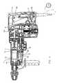
- FIG. 1Ashows a sectional view of a hammer drill and/or percussion hammer (hammer) according to a first specific embodiment, in percussion operation;
- FIG. 1Bshows an enlarged detail from FIG. 1A ;
- FIG. 2shows an enlarged detail of the first specific embodiment according to FIG. 1A , but in no-load operation with the tool seated on the stone;
- FIG. 3Ashows a sectional view of the hammer according to the first specific embodiment in no-load operation, with the tool lifted off of the stone;
- FIG. 3Bshows an enlarged detail from FIG. 3A ;
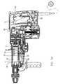
- FIG. 4shows a sectional view of a hammer according to the present invention in a second specific embodiment, in percussive operation
- FIG. 5Ashows the hammer of FIG. 4 in no-load operation
- FIG. 5Bshows an enlarged detail of FIG. 5 A.
- FIGS. 1A to 3 Bshow the hammer according to a first specific embodiment in different operating states and different detail enlargements.
- the hammer according to the second specific embodimentis shown in FIGS. 4 to 5 B.
- the hammer according to the first specific embodimentis described on the basis of FIGS. 1A and 1B .
- a handle 2On a hammer housing 1 , a handle 2 is attached so as to be capable of axial displacement via spring systems 3 .
- an additional handle 4On the front end of hammer housing 1 , an additional handle 4 is fastened, which however is not important for the present invention and serves only for the improved guiding of the hammer.
- Spring system 3can be for example an anti-vibration system for mitigating the vibrations and impacts—acting on handle 2 and produced by the air spring hammer mechanism or by the action of the tool—on handle 2 , and thus on the operator's hand, which grasps handle 2 at a grasping point 2 b .
- an anti-vibration systemfor mitigating the vibrations and impacts—acting on handle 2 and produced by the air spring hammer mechanism or by the action of the tool—on handle 2 , and thus on the operator's hand, which grasps handle 2 at a grasping point 2 b .
- an anti-vibration systemis already provided in a known hammer, no design modifications would need to be carried out at this location.
- a main switch 5for switching the hammer on and off.
- a line cable 6is connected to handle 2 .
- an electric motor 7that drives a crankshaft 9 via a gear mechanism 8 .
- crankshaft 9produces a back-and-forth movement of a hollow drive piston 11 .
- a percussion piston 12is accommodated so as to be capable of axial movement.
- Rivet header 14comes into contact with a shaft, accommodated in a tool holder 15 , of a tool (not shown).
- a front hollow space 16that, in percussion operation, stands in communicating connection with the surrounding environment of the air spring hammer mechanism, i.e. for example the rest of the interior of hammer housing 1 , via an air channel 18 provided in a wall 17 of drive piston 11 .
- the formation of an air cushion before percussion piston 12 in front hollow space 16which could hinder the percussion effect of percussion piston 12 , is avoided.
- Control sleeve 19can be moved axially in a hammer mechanism housing 20 that forms a part of hammer housing 1 .
- a collar 21is provided on control sleeve 19 that is surrounded by a dog 22 .
- dog 22is connected directly with an extension 2 a of handle 2 , so that a positively locking coupling that is effective at least in the axial direction of control sleeve 19 is realized between handle 2 and control sleeve 19 .
- handle 2can be moved relative to hammer housing 1 on the basis of the action of spring system 3 , its movement is transmitted directly to control sleeve 19 via dog 22 and collar 21 , and displaces control sleeve 19 axially in the interior of hammer mechanism housing 20 .
- Control sleeve 19has a radial opening 23 that penetrates its wall.
- the position of radial opening 23is selected such that in each operating state it corresponds with at least one opening 24 in wall 17 of drive piston 11 , a plurality of openings 24 being formed in wall 17 in the axial direction of drive piston 11 (as is shown clearly in FIG. 1B in particular).
- at least one, possibly also two, openings 24are situated at the level of radial opening 23 .
- an opening 25is formed, e.g. in the form of an annular channel surrounding control sleeve 19 , said channel opening on its underside towards the interior of hammer housing 1 , i.e., to the surrounding environment of the air spring hammer mechanism.
- FIGS. 1A and 1Bshow the hammer, and in particular the air spring hammer mechanism, in percussion operation.
- control sleeve 19is displaced in hammer mechanism housing 20 in such a way that radial opening 23 does not stand over recess 25 .
- the connectionis broken.
- Control sleeve 19together with radial opening 23 accommodated by it, represents a valve for opening and closing the no-load channel.
- control sleeve 19The corresponding position of control sleeve 19 is effected in that the operator pushes handle 2 forward, against hammer housing 1 and against the action of spring system's 3 . Correspondingly, he also presses the tool against the stone to be processed.
- the relative displacement of handle 2 in relation to hammer housing 1which is proportional to the pressure force, is transmitted directly onto control sleeve 19 , so that the desired axial position of control sleeve 19 , shown in FIGS. 1A and 1B , results.
- a seal(not shown in the Figures) is provided that prevents dirt from penetrating into the interior of the hammer housing.
- FIG. 2shows an enlarged detail of the hammer from FIG. 1A , here however in no-load operation, in which the tool rests on the stone to be processed without pressure from the operator.
- rivet header 14is in its rear position, displaced into the interior of hammer housing 1 .
- control sleeve 19Due to the displacement of control sleeve 19 , in addition a second radial opening 26 formed therein has been displaced axially in such a way that air channel 18 , which connects front hollow space 16 to the surrounding environment, is interrupted. Correspondingly, front hollow space 16 is decoupled from the surrounding environment, so that a supply of air that remains in its interior forms an air cushion that counteracts a further impact by percussion piston 12 .
- FIGS. 3A and 3Bshow the hammer according to the present invention in no-load operation when the tool is lifted completely off the stone.
- rivet header 14is situated in its front position, because the tool has slid out of hammer housing 1 .
- FIGS. 4 , 5 A, and 5 Bshow the hammer according to the present invention in a second specific embodiment. While the above-described first specific embodiment enables a purely mechanical way of recognizing the pressure force applied to the handle by the operator, and a resulting influencing of the position of the valve that controls the connection of hollow space 13 with the surrounding environment, the second specific embodiment is based on a mechanical/electronic solution. Insofar as components are used that are identical to those in the first specific embodiment, the same reference characters are also provided. A repeated description of the corresponding elements is omitted.
- valve element 30is placed in the no-load channel, which channel is very short in the second specific embodiment.
- the no-load channelconsists only of a recess 31 in percussion mechanism housing 20 and a connecting channel 32 in which valve element 30 is placed.
- Valve element 30has a penetrating bored hole 33 in its interior.
- valve element 30is capable of rotation.
- an actuating element(not shown in the Figures) is provided.
- valve element 30While in FIG. 4 valve element 30 is rotated into a position in which bored hole 33 is not situated in the no-load channel, so that the connection between hollow space 13 and the surrounding environment of the air spring hammer mechanism is broken, in FIGS. 5A and 5B a position of valve element 30 can be seen in which bored hole 33 opens the no-load channel, and creates the connection between hollow space 13 and the surrounding environment.
- handle 2is attached so as to be capable of motion relative to hammer housing 1 , against the action of spring system 3 .
- the relative position between handle 2 and hammer housing 1is acquired with the aid of a proximity sensor 34 .
- Proximity sensor 34can either be designed in such a way that it is capable of distinguishing only binary states, namely percussion operation/no-load operation, or, alternatively, with the aid of a suitable proximity sensor it is also possible to acquire the precise position of handle 2 relative to hammer housing 1 and to evaluate it correspondingly.
- a suitable force measurement sensorcan also be provided (for example in the interior of spring system 3 , but also independent of spring systems), that acquires the pressure force applied by the operator.
- a touch-sensitive force measurement sensor in handle 2 itselfit is possible to acquire the pressure force applied by the operator directly at grasping point 2 b.
- Proximity sensor 34produces a pressure signal that corresponds to the pressure force (whether binary or proportional to the pressure force) and forwards it to a control unit 35 . If control unit 35 recognizes that the operator is pressing the hammer so as to indicate that a transition from the no-load setting to the percussion setting is desired, control unit 35 controls the valve actuating element (not shown) in order to rotate valve element 30 into the position shown in FIG. 4 . When the hammer is lifted, and the pressure force is correspondingly relieved, the reverse procedure is introduced.
- a position sensoris provided that acquires the position of the hammer in space, in particular the angle of inclination of the tool axis, and emits a corresponding position signal to control unit 35 .
- Control unit 35evaluates the position signal in such a way that the weight forces, resulting from the position and thus the working orientation, of the tool and of the hammer (which, given a work position oriented upward, must be additionally supported by the operator at handle 2 , or which in the case of downward orientation act on the tool and support the impact), can be taken into account in the evaluation of the pressure signal. In this way, the pressure forces, which otherwise vary greatly due to the effect of gravitation, can be compensated in accordance with the orientation of use.
- Both the mechanical solution according to the first specific embodiment and also the mechatronic solution of the additionally described specific embodimentsenable a particularly gradual running up of the hammer.
- the operatorcan carefully place the tip of the tool at the desired position, and by increasing the pressure force can effect a displacement of handle 2 , and thus a gradual introduction of percussion operation.
Landscapes
- Engineering & Computer Science (AREA)
- Mechanical Engineering (AREA)
- Percussive Tools And Related Accessories (AREA)
- Drilling And Boring (AREA)
Abstract
Description
Claims (19)
Applications Claiming Priority (3)
| Application Number | Priority Date | Filing Date | Title |
|---|---|---|---|
| DE10145464.3 | 2001-09-14 | ||
| DE10145464ADE10145464C2 (en) | 2001-09-14 | 2001-09-14 | Drill and / or impact hammer with idle control depending on the contact pressure |
| PCT/EP2002/010253WO2003024672A1 (en) | 2001-09-14 | 2002-09-12 | Hammer drill and/or percussion hammer with no-load operation control that depends on application pressure |
Publications (2)
| Publication Number | Publication Date |
|---|---|
| US20040177981A1 US20040177981A1 (en) | 2004-09-16 |
| US6913088B2true US6913088B2 (en) | 2005-07-05 |
Family
ID=7699118
Family Applications (1)
| Application Number | Title | Priority Date | Filing Date |
|---|---|---|---|
| US10/485,673Expired - Fee RelatedUS6913088B2 (en) | 2001-09-14 | 2002-09-12 | Hammer drill and /or percussion hammer with no-load operation control that depends on application pressure |
Country Status (6)
| Country | Link |
|---|---|
| US (1) | US6913088B2 (en) |
| EP (1) | EP1425138B1 (en) |
| JP (1) | JP4243539B2 (en) |
| DE (2) | DE10145464C2 (en) |
| ES (1) | ES2243767T3 (en) |
| WO (1) | WO2003024672A1 (en) |
Cited By (31)
| Publication number | Priority date | Publication date | Assignee | Title |
|---|---|---|---|---|
| US20050023017A1 (en)* | 2003-07-31 | 2005-02-03 | Makita Corporation | Power tool |
| US20060076154A1 (en)* | 2003-04-01 | 2006-04-13 | Makita Corporation | Power tool |
| US20060144602A1 (en)* | 2004-12-23 | 2006-07-06 | Klaus-Dieter Arich | Power tool cooling |
| US20060144604A1 (en)* | 2004-12-23 | 2006-07-06 | Martin Soika | Power tool housing |
| US20060156858A1 (en)* | 2004-12-23 | 2006-07-20 | Martin Soika | Power tool housing |
| US20070039749A1 (en)* | 2005-08-19 | 2007-02-22 | Makita Corporation | Impact power tool |
| US20080047724A1 (en)* | 2006-07-27 | 2008-02-28 | Axel Fischer | Hand-held power tool with a decoupling device |
| US20080210447A1 (en)* | 2007-01-10 | 2008-09-04 | Aeg Electric Tools Gmbh | Portable Hand-Guided Power Tool |
| US20090014195A1 (en)* | 2007-07-11 | 2009-01-15 | Black & Decker Inc. | Rotary Hammer |
| US20090236111A1 (en)* | 2008-03-18 | 2009-09-24 | Black And Decker Inc. | Hammer |
| US20090236112A1 (en)* | 2008-03-18 | 2009-09-24 | Black And Decker Inc. | Hammer |
| US20090272553A1 (en)* | 2006-11-03 | 2009-11-05 | Uwe Engelfried | Hand-held power tool with a vibration-damped handle with a switch |
| US20090321101A1 (en)* | 2008-06-26 | 2009-12-31 | Makita Corporation | Power tool |
| US20100051304A1 (en)* | 2008-08-29 | 2010-03-04 | Makita Corporation | Impact tool |
| US20100071920A1 (en)* | 2008-09-19 | 2010-03-25 | James Ching Sik Lau | Power tool |
| US20100236801A1 (en)* | 2009-03-23 | 2010-09-23 | Makita Corporation | Impact tool |
| US20110120741A1 (en)* | 2008-05-09 | 2011-05-26 | Kurt Limberg | Auxiliary handle for use with a power tool |
| US20140352114A1 (en)* | 2013-05-29 | 2014-12-04 | Makita Corporation | Auxiliary handle and reciprocating power tool having the same |
| US20150246438A1 (en)* | 2012-09-03 | 2015-09-03 | Makita Corporation | Hammer tool |
| US9308636B2 (en) | 2012-02-03 | 2016-04-12 | Milwaukee Electric Tool Corporation | Rotary hammer with vibration dampening |
| WO2016140917A1 (en)* | 2015-03-02 | 2016-09-09 | Sikorsky Aircraft Corporation | Pneumatic tool system |
| US20170120408A1 (en)* | 2015-10-30 | 2017-05-04 | Sears Brands, L.L.C. | Position feedback control method and power tool |
| US20170341214A1 (en)* | 2014-11-21 | 2017-11-30 | Hilti Aktiengesellschaft | Hand-held power tool gearbox closure and hand-held power tool |
| US20180370007A1 (en)* | 2015-12-15 | 2018-12-27 | Hilti Aktiengesellschaft | Percussive power tool |
| US10821308B1 (en)* | 2015-09-21 | 2020-11-03 | David Krumrei | Battering ram |
| US11077533B2 (en) | 2008-05-09 | 2021-08-03 | Milwaukee Electric Tool Corporation | Power tool dust collector |
| US11084006B2 (en) | 2017-03-23 | 2021-08-10 | Milwaukee Electric Tool Corporation | Mud mixer |
| US20220266435A1 (en)* | 2021-02-22 | 2022-08-25 | Makita Corporation | Power tool having hammer mechanism |
| US20230026934A1 (en)* | 2021-07-26 | 2023-01-26 | Makita Corporation | Striking tool |
| US11565392B2 (en)* | 2019-03-26 | 2023-01-31 | Makita Corporation | Dust collecting system |
| US11992926B2 (en)* | 2020-05-25 | 2024-05-28 | Robert Bosch Gmbh | Hand-held power tool |
Families Citing this family (31)
| Publication number | Priority date | Publication date | Assignee | Title |
|---|---|---|---|---|
| DE10333799B3 (en)* | 2003-07-24 | 2005-02-17 | Wacker Construction Equipment Ag | Hollow piston impact mechanism with air compensation and idling opening |
| DE102004034268B3 (en)* | 2004-07-15 | 2005-12-29 | Wacker Construction Equipment Ag | Rotary hammer with safety coupling |
| DE102005028918A1 (en)* | 2005-06-22 | 2006-12-28 | Wacker Construction Equipment Ag | Drilling and/or percussive hammer for making holes has delay device controlling valve during closing |
| DE102006010892A1 (en)* | 2006-03-09 | 2007-09-13 | Robert Bosch Gmbh | Machine tool and method for operating a machine tool |
| JP4867464B2 (en)* | 2006-05-10 | 2012-02-01 | マックス株式会社 | Drill |
| DE102006060320A1 (en) | 2006-12-20 | 2008-06-26 | Robert Bosch Gmbh | Schlagwerk for a hand tool |
| JP5412249B2 (en)* | 2009-11-19 | 2014-02-12 | 株式会社マキタ | Hand tool |
| JP5502458B2 (en) | 2009-12-25 | 2014-05-28 | 株式会社マキタ | Impact tool |
| DE102011007660A1 (en)* | 2011-04-19 | 2012-10-25 | Hilti Aktiengesellschaft | Hand tool and manufacturing process |
| DE102012005803A1 (en) | 2012-03-21 | 2013-09-26 | Wacker Neuson Produktion GmbH & Co. KG | Drilling and / or hammer with load-dependent adaptation of the stroke rate |
| DE102012208891A1 (en)* | 2012-05-25 | 2013-11-28 | Robert Bosch Gmbh | Pneumatic impact mechanism |
| WO2013174641A1 (en)* | 2012-05-25 | 2013-11-28 | Robert Bosch Gmbh | Percussion unit |
| CN104334317A (en)* | 2012-05-25 | 2015-02-04 | 罗伯特·博世有限公司 | Percussion mechanism unit |
| DE102012208870A1 (en)* | 2012-05-25 | 2013-11-28 | Robert Bosch Gmbh | Percussion unit |
| DE102012208986A1 (en)* | 2012-05-29 | 2013-12-05 | Hilti Aktiengesellschaft | Chiseling machine tool |
| DE102012210088A1 (en)* | 2012-06-15 | 2013-12-19 | Hilti Aktiengesellschaft | machine tool |
| EP2821183B1 (en) | 2013-07-05 | 2017-06-21 | Black & Decker Inc. | Hammer Drill |
| EP2857150A1 (en)* | 2013-10-03 | 2015-04-08 | HILTI Aktiengesellschaft | Manual tool machine |
| JP6335049B2 (en)* | 2014-07-03 | 2018-05-30 | 株式会社マキタ | Impact tool |
| EP3009236A1 (en)* | 2014-10-16 | 2016-04-20 | HILTI Aktiengesellschaft | Chiselling hand-held machine tool |
| EP3281747A1 (en)* | 2016-08-09 | 2018-02-14 | HILTI Aktiengesellschaft | Handheld machine tool |
| JP6757226B2 (en) | 2016-10-07 | 2020-09-16 | 株式会社マキタ | Electric tool |
| JP6981744B2 (en) | 2016-10-07 | 2021-12-17 | 株式会社マキタ | Hammer drill |
| JP6863705B2 (en)* | 2016-10-07 | 2021-04-21 | 株式会社マキタ | Electric tool |
| DE102017121668A1 (en)* | 2017-09-19 | 2019-03-21 | Erwin Schmucker | Impact tool for machining workpieces |
| JP7282608B2 (en)* | 2018-09-10 | 2023-05-29 | 株式会社マキタ | impact tool |
| DE102019124134A1 (en) | 2018-09-10 | 2020-03-12 | Makita Corporation | Work tool |
| US20220055198A1 (en)* | 2020-08-24 | 2022-02-24 | Makita Corporation | Power tool having hammer mechanism |
| DE102020212425A1 (en)* | 2020-10-01 | 2022-04-07 | Robert Bosch Gesellschaft mit beschränkter Haftung | Bearing flange for a drive system of a hand-held power tool, as well as a rotary hammer with a percussion mechanism and a bearing flange |
| JP7624319B2 (en)* | 2021-02-04 | 2025-01-30 | 株式会社マキタ | Impact tools |
| JP7585085B2 (en)* | 2021-02-22 | 2024-11-18 | 株式会社マキタ | Impact tools |
Citations (20)
| Publication number | Priority date | Publication date | Assignee | Title |
|---|---|---|---|---|
| DE323766C (en) | 1919-03-28 | 1920-08-06 | Carl Scholz | Jackhammer |
| GB242218A (en) | 1924-10-29 | 1926-03-11 | Ingersoll Rand Co | Improvement in pneumatic hammer tool |
| US4074777A (en)* | 1974-08-08 | 1978-02-21 | Atlas Copco Aktiebolag | Pneumatic impact tool |
| US4222443A (en)* | 1978-07-21 | 1980-09-16 | Hilti Aktiengesellschaft | Motor-driven hammer drill |
| US4305473A (en)* | 1977-10-17 | 1981-12-15 | Atlas Copco Aktiebolag | Power control device for pneumatic motors |
| US4388972A (en)* | 1980-04-25 | 1983-06-21 | Atlas Copco Aktiebolag | Vibrationless impact tool |
| US4483402A (en)* | 1981-12-01 | 1984-11-20 | Thor Power Tool Company | Paving breaker |
| US5161623A (en)* | 1990-01-15 | 1992-11-10 | Sulzer Brothers Limited | Percussion device |
| US5533579A (en)* | 1994-10-31 | 1996-07-09 | Chu; Eric | Shock preventive pneumatic tool as automatically shut off under no load condition |
| DE19713154A1 (en) | 1996-03-29 | 1997-10-30 | Makita Corp | Striking tool e.g. electric hammer, percussion drill |
| DE19714288A1 (en) | 1997-04-07 | 1998-10-08 | Hilti Ag | Drilling and / or chiseling device |
| DE19724531A1 (en) | 1997-06-11 | 1998-12-17 | Bosch Gmbh Robert | Hammer drill |
| WO2000016948A1 (en)* | 1998-09-23 | 2000-03-30 | Wacker-Werke Gmbh & Co. Kg | Pneumatic percussion power tool with pneumatic returning spring |
| DE19847687A1 (en) | 1998-10-15 | 2000-04-27 | Wacker Werke Kg | Hammer drill or hammer tool with an air spring has a connecting opening to link the air spring zone with the ambient atmosphere on idle running for a smooth change between working and idle running modes |
| US6076616A (en)* | 1996-11-12 | 2000-06-20 | Wacker-Werke Gmbh & Co. Kg | Working tool which can be guided in a grab handle |
| US6209659B1 (en)* | 1998-07-22 | 2001-04-03 | Hilti Aktiengesellschaft | Hand-held drill with a compressed air-operated hammer mechanism |
| US6237700B1 (en)* | 1998-06-25 | 2001-05-29 | Wacker-Werke Gmbh & Co. Kg | Pneumatic impact mechanism with a drive piston having a reduced wall thickness |
| US20020003045A1 (en)* | 2000-07-08 | 2002-01-10 | Hans-Werner Bongers-Ambrosius | Electric hand tool implement with no-load stroke disconnection |
| WO2002072315A1 (en)* | 2001-03-12 | 2002-09-19 | Wacker Construction Equipment Ag | Pneumatic percussive tool with a movement frequency controlled idling position |
| US6691798B1 (en)* | 2002-06-19 | 2004-02-17 | Steven James Lindsay | Variable hand pressure activated power tool |
Family Cites Families (1)
| Publication number | Priority date | Publication date | Assignee | Title |
|---|---|---|---|---|
| DE10034359A1 (en)* | 2000-07-14 | 2002-01-24 | Hilti Ag | Hitting electric hand tool device |
- 2001
- 2001-09-14DEDE10145464Apatent/DE10145464C2/ennot_activeExpired - Fee Related
- 2002
- 2002-09-12DEDE50203692Tpatent/DE50203692D1/ennot_activeExpired - Lifetime
- 2002-09-12JPJP2003528359Apatent/JP4243539B2/ennot_activeExpired - Fee Related
- 2002-09-12EPEP02777083Apatent/EP1425138B1/ennot_activeExpired - Lifetime
- 2002-09-12WOPCT/EP2002/010253patent/WO2003024672A1/enactiveIP Right Grant
- 2002-09-12ESES02777083Tpatent/ES2243767T3/ennot_activeExpired - Lifetime
- 2002-09-12USUS10/485,673patent/US6913088B2/ennot_activeExpired - Fee Related
Patent Citations (20)
| Publication number | Priority date | Publication date | Assignee | Title |
|---|---|---|---|---|
| DE323766C (en) | 1919-03-28 | 1920-08-06 | Carl Scholz | Jackhammer |
| GB242218A (en) | 1924-10-29 | 1926-03-11 | Ingersoll Rand Co | Improvement in pneumatic hammer tool |
| US4074777A (en)* | 1974-08-08 | 1978-02-21 | Atlas Copco Aktiebolag | Pneumatic impact tool |
| US4305473A (en)* | 1977-10-17 | 1981-12-15 | Atlas Copco Aktiebolag | Power control device for pneumatic motors |
| US4222443A (en)* | 1978-07-21 | 1980-09-16 | Hilti Aktiengesellschaft | Motor-driven hammer drill |
| US4388972A (en)* | 1980-04-25 | 1983-06-21 | Atlas Copco Aktiebolag | Vibrationless impact tool |
| US4483402A (en)* | 1981-12-01 | 1984-11-20 | Thor Power Tool Company | Paving breaker |
| US5161623A (en)* | 1990-01-15 | 1992-11-10 | Sulzer Brothers Limited | Percussion device |
| US5533579A (en)* | 1994-10-31 | 1996-07-09 | Chu; Eric | Shock preventive pneumatic tool as automatically shut off under no load condition |
| DE19713154A1 (en) | 1996-03-29 | 1997-10-30 | Makita Corp | Striking tool e.g. electric hammer, percussion drill |
| US6076616A (en)* | 1996-11-12 | 2000-06-20 | Wacker-Werke Gmbh & Co. Kg | Working tool which can be guided in a grab handle |
| DE19714288A1 (en) | 1997-04-07 | 1998-10-08 | Hilti Ag | Drilling and / or chiseling device |
| DE19724531A1 (en) | 1997-06-11 | 1998-12-17 | Bosch Gmbh Robert | Hammer drill |
| US6237700B1 (en)* | 1998-06-25 | 2001-05-29 | Wacker-Werke Gmbh & Co. Kg | Pneumatic impact mechanism with a drive piston having a reduced wall thickness |
| US6209659B1 (en)* | 1998-07-22 | 2001-04-03 | Hilti Aktiengesellschaft | Hand-held drill with a compressed air-operated hammer mechanism |
| WO2000016948A1 (en)* | 1998-09-23 | 2000-03-30 | Wacker-Werke Gmbh & Co. Kg | Pneumatic percussion power tool with pneumatic returning spring |
| DE19847687A1 (en) | 1998-10-15 | 2000-04-27 | Wacker Werke Kg | Hammer drill or hammer tool with an air spring has a connecting opening to link the air spring zone with the ambient atmosphere on idle running for a smooth change between working and idle running modes |
| US20020003045A1 (en)* | 2000-07-08 | 2002-01-10 | Hans-Werner Bongers-Ambrosius | Electric hand tool implement with no-load stroke disconnection |
| WO2002072315A1 (en)* | 2001-03-12 | 2002-09-19 | Wacker Construction Equipment Ag | Pneumatic percussive tool with a movement frequency controlled idling position |
| US6691798B1 (en)* | 2002-06-19 | 2004-02-17 | Steven James Lindsay | Variable hand pressure activated power tool |
Cited By (57)
| Publication number | Priority date | Publication date | Assignee | Title |
|---|---|---|---|---|
| US20060076154A1 (en)* | 2003-04-01 | 2006-04-13 | Makita Corporation | Power tool |
| US7252157B2 (en)* | 2003-04-01 | 2007-08-07 | Makita Corporation | Power tool |
| US7204322B2 (en)* | 2003-07-31 | 2007-04-17 | Makita Corporation | Power tool having pneumatic vibration dampening |
| US20050023017A1 (en)* | 2003-07-31 | 2005-02-03 | Makita Corporation | Power tool |
| US20060144604A1 (en)* | 2004-12-23 | 2006-07-06 | Martin Soika | Power tool housing |
| US20060156858A1 (en)* | 2004-12-23 | 2006-07-20 | Martin Soika | Power tool housing |
| US20060144602A1 (en)* | 2004-12-23 | 2006-07-06 | Klaus-Dieter Arich | Power tool cooling |
| US8430182B2 (en) | 2004-12-23 | 2013-04-30 | Black & Decker Inc. | Power tool housing |
| US7705497B2 (en) | 2004-12-23 | 2010-04-27 | Black & Decker Inc. | Power tool cooling |
| US20070039749A1 (en)* | 2005-08-19 | 2007-02-22 | Makita Corporation | Impact power tool |
| US7383895B2 (en)* | 2005-08-19 | 2008-06-10 | Makita Corporation | Impact power tool |
| US7610967B2 (en)* | 2006-07-27 | 2009-11-03 | Hil Aktiengesellschaft | Hand-held power tool with a decoupling device |
| US20080047724A1 (en)* | 2006-07-27 | 2008-02-28 | Axel Fischer | Hand-held power tool with a decoupling device |
| US7971656B2 (en)* | 2006-11-03 | 2011-07-05 | Robert Bosch Gmbh | Hand-held power tool with a vibration-damped handle with a switch |
| US20090272553A1 (en)* | 2006-11-03 | 2009-11-05 | Uwe Engelfried | Hand-held power tool with a vibration-damped handle with a switch |
| US7591325B2 (en)* | 2007-01-10 | 2009-09-22 | Aeg Electric Tools Gmbh | Portable hand-guided power tool |
| US20080210447A1 (en)* | 2007-01-10 | 2008-09-04 | Aeg Electric Tools Gmbh | Portable Hand-Guided Power Tool |
| US7721819B2 (en)* | 2007-07-11 | 2010-05-25 | Black & Decker Inc. | Rotary hammer |
| US20090014195A1 (en)* | 2007-07-11 | 2009-01-15 | Black & Decker Inc. | Rotary Hammer |
| US20090236112A1 (en)* | 2008-03-18 | 2009-09-24 | Black And Decker Inc. | Hammer |
| US20090236111A1 (en)* | 2008-03-18 | 2009-09-24 | Black And Decker Inc. | Hammer |
| US7987921B2 (en)* | 2008-03-18 | 2011-08-02 | Black & Decker Inc. | Hammer |
| US7886838B2 (en)* | 2008-03-18 | 2011-02-15 | Black & Decker Inc. | Hammer |
| US11883917B2 (en) | 2008-05-09 | 2024-01-30 | Milwaukee Electric Tool Corporation | Power tool dust collector |
| US11077533B2 (en) | 2008-05-09 | 2021-08-03 | Milwaukee Electric Tool Corporation | Power tool dust collector |
| US8813868B2 (en) | 2008-05-09 | 2014-08-26 | Milwaukee Electric Tool Corporation | Auxiliary handle for use with a power tool |
| US20110120741A1 (en)* | 2008-05-09 | 2011-05-26 | Kurt Limberg | Auxiliary handle for use with a power tool |
| US20130098648A1 (en)* | 2008-06-26 | 2013-04-25 | Masanori Furusawa | Power tool |
| US20090321101A1 (en)* | 2008-06-26 | 2009-12-31 | Makita Corporation | Power tool |
| US7967078B2 (en)* | 2008-08-29 | 2011-06-28 | Makita Corporation | Impact tool |
| US20100051304A1 (en)* | 2008-08-29 | 2010-03-04 | Makita Corporation | Impact tool |
| US20100071920A1 (en)* | 2008-09-19 | 2010-03-25 | James Ching Sik Lau | Power tool |
| US20100236801A1 (en)* | 2009-03-23 | 2010-09-23 | Makita Corporation | Impact tool |
| US8286724B2 (en)* | 2009-03-23 | 2012-10-16 | Makita Corporation | Impact tool |
| US9308636B2 (en) | 2012-02-03 | 2016-04-12 | Milwaukee Electric Tool Corporation | Rotary hammer with vibration dampening |
| US10195730B2 (en) | 2012-02-03 | 2019-02-05 | Milwaukee Electric Tool Corporation | Rotary hammer |
| US10052747B2 (en)* | 2012-09-03 | 2018-08-21 | Makita Corporation | Hammer tool |
| US20150246438A1 (en)* | 2012-09-03 | 2015-09-03 | Makita Corporation | Hammer tool |
| US20140352114A1 (en)* | 2013-05-29 | 2014-12-04 | Makita Corporation | Auxiliary handle and reciprocating power tool having the same |
| US9463566B2 (en)* | 2013-05-29 | 2016-10-11 | Makita Corporation | Auxiliary handle and reciprocating power tool having the same |
| US20170341214A1 (en)* | 2014-11-21 | 2017-11-30 | Hilti Aktiengesellschaft | Hand-held power tool gearbox closure and hand-held power tool |
| WO2016140917A1 (en)* | 2015-03-02 | 2016-09-09 | Sikorsky Aircraft Corporation | Pneumatic tool system |
| US10675672B2 (en) | 2015-03-02 | 2020-06-09 | Sikorsky Aircraft Corporation | Pneumatic tool system |
| US10821308B1 (en)* | 2015-09-21 | 2020-11-03 | David Krumrei | Battering ram |
| US10377008B2 (en)* | 2015-10-30 | 2019-08-13 | Transform Sr Brands Llc | Position feedback control method and power tool |
| US11752586B2 (en) | 2015-10-30 | 2023-09-12 | Transform Sr Brands Llc | Position feedback control method and power tool |
| US20170120408A1 (en)* | 2015-10-30 | 2017-05-04 | Sears Brands, L.L.C. | Position feedback control method and power tool |
| US12048976B2 (en) | 2015-10-30 | 2024-07-30 | Transform Sr Brands Llc | Position feedback control method and power tool |
| US10821589B2 (en)* | 2015-12-15 | 2020-11-03 | Hilti Aktiengesellschaft | Percussive power tool |
| US20180370007A1 (en)* | 2015-12-15 | 2018-12-27 | Hilti Aktiengesellschaft | Percussive power tool |
| US11084006B2 (en) | 2017-03-23 | 2021-08-10 | Milwaukee Electric Tool Corporation | Mud mixer |
| US12194424B2 (en) | 2017-03-23 | 2025-01-14 | Milwaukee Electric Tool Corporation | Mud mixer |
| US11565392B2 (en)* | 2019-03-26 | 2023-01-31 | Makita Corporation | Dust collecting system |
| US11992926B2 (en)* | 2020-05-25 | 2024-05-28 | Robert Bosch Gmbh | Hand-held power tool |
| US20220266435A1 (en)* | 2021-02-22 | 2022-08-25 | Makita Corporation | Power tool having hammer mechanism |
| US11833653B2 (en)* | 2021-02-22 | 2023-12-05 | Makita Corporation | Power tool having hammer mechanism |
| US20230026934A1 (en)* | 2021-07-26 | 2023-01-26 | Makita Corporation | Striking tool |
Also Published As
| Publication number | Publication date |
|---|---|
| ES2243767T3 (en) | 2005-12-01 |
| DE10145464A1 (en) | 2003-04-10 |
| US20040177981A1 (en) | 2004-09-16 |
| JP2005502488A (en) | 2005-01-27 |
| DE50203692D1 (en) | 2005-08-25 |
| DE10145464C2 (en) | 2003-08-28 |
| EP1425138A1 (en) | 2004-06-09 |
| WO2003024672A1 (en) | 2003-03-27 |
| JP4243539B2 (en) | 2009-03-25 |
| EP1425138B1 (en) | 2005-07-20 |
Similar Documents
| Publication | Publication Date | Title |
|---|---|---|
| US6913088B2 (en) | Hammer drill and /or percussion hammer with no-load operation control that depends on application pressure | |
| US8235136B2 (en) | Drilling and/or percussive hammer with no-load operation control | |
| US6116352A (en) | Drilling and/or percussion power tool | |
| JP5202010B2 (en) | Hand-held tool device having a pneumatic striking mechanism | |
| US7320368B2 (en) | Power impact tool | |
| US7677327B2 (en) | Percussion mechanism for a repetitively hammering hand power tool | |
| JP5086505B2 (en) | Electric hand tool device | |
| US6938704B2 (en) | Pneumatic percussive tool with a movement frequency controlled idling position | |
| US7726414B2 (en) | Hollow piston hammer device with air equilibration and idle openings | |
| US6467555B2 (en) | Percussion mechanism for an electrical hand-held tool with a blank blow cut-off | |
| FI65723B (en) | MOTORRIVEN BORRNINGSHAMMARE | |
| EP0974428A3 (en) | Handheld drilling machine with compressed-air-operated percussion mechanism | |
| JP2002337066A (en) | Nail driving guide mechanism for nailing machine | |
| EP1223010B1 (en) | Percussion hammer | |
| CN110785264A (en) | Hand-held power tool | |
| US6808026B2 (en) | Pneumatic percussive tool with a short working drive piston | |
| US4102534A (en) | Pneumatic hammer | |
| SE501276C2 (en) | Handheld striking machine | |
| CN100421879C (en) | hand tool machine | |
| EP0280195A2 (en) | Percussion apparatus with tool holder | |
| GB2114495A (en) | Impact tool | |
| GB2410916A (en) | Hand held machine tool having clutch | |
| US6298923B1 (en) | Impacting device for releasing blocked objects by impact | |
| JPH032633B2 (en) |
Legal Events
| Date | Code | Title | Description |
|---|---|---|---|
| AS | Assignment | Owner name:WACKER CONSTRUTION EQUIPMENT AG, GERMANY Free format text:ASSIGNMENT OF ASSIGNORS INTEREST;ASSIGNORS:BERGER, RUDOLF;SCHMID, WOLFGANG;REEL/FRAME:015406/0309 Effective date:20040113 | |
| CC | Certificate of correction | ||
| FPAY | Fee payment | Year of fee payment:4 | |
| AS | Assignment | Owner name:WACKER NEUSON SE,GERMANY Free format text:CHANGE OF NAME;ASSIGNOR:WACKER CONSTRUCTION EQUIPMENT AG;REEL/FRAME:024515/0259 Effective date:20091002 Owner name:WACKER NEUSON SE, GERMANY Free format text:CHANGE OF NAME;ASSIGNOR:WACKER CONSTRUCTION EQUIPMENT AG;REEL/FRAME:024515/0259 Effective date:20091002 | |
| AS | Assignment | Owner name:WACKER NEUSON PRODUKTION GMBH & CO. KG, GERMANY Free format text:NUNC PRO TUNC ASSIGNMENT;ASSIGNOR:WACKER NEUSON SE;REEL/FRAME:026955/0859 Effective date:20110829 | |
| FPAY | Fee payment | Year of fee payment:8 | |
| REMI | Maintenance fee reminder mailed | ||
| LAPS | Lapse for failure to pay maintenance fees | ||
| STCH | Information on status: patent discontinuation | Free format text:PATENT EXPIRED DUE TO NONPAYMENT OF MAINTENANCE FEES UNDER 37 CFR 1.362 | |
| FP | Expired due to failure to pay maintenance fee | Effective date:20170705 |