US6910607B2 - Cover for dispensing closure with pressure actuated valve - Google Patents
Cover for dispensing closure with pressure actuated valveDownload PDFInfo
- Publication number
- US6910607B2 US6910607B2US10/098,819US9881902AUS6910607B2US 6910607 B2US6910607 B2US 6910607B2US 9881902 AUS9881902 AUS 9881902AUS 6910607 B2US6910607 B2US 6910607B2
- Authority
- US
- United States
- Prior art keywords
- base
- closure
- valve
- cover
- container
- Prior art date
- Legal status (The legal status is an assumption and is not a legal conclusion. Google has not performed a legal analysis and makes no representation as to the accuracy of the status listed.)
- Expired - Fee Related, expires
Links
- 230000013011matingEffects0.000claimsabstractdescription4
- 238000007789sealingMethods0.000claimsdescription20
- 230000004044responseEffects0.000claimsdescription8
- 230000002829reductive effectEffects0.000claimsdescription5
- 239000011324beadSubstances0.000claims7
- 230000008878couplingEffects0.000claims4
- 238000010168coupling processMethods0.000claims4
- 238000005859coupling reactionMethods0.000claims4
- 230000001747exhibiting effectEffects0.000claims2
- 230000002401inhibitory effectEffects0.000claims2
- XLYOFNOQVPJJNP-UHFFFAOYSA-NwaterSubstancesOXLYOFNOQVPJJNP-UHFFFAOYSA-N0.000description5
- 230000009471actionEffects0.000description3
- -1conditionersSubstances0.000description3
- 238000013461designMethods0.000description3
- 239000000463materialSubstances0.000description3
- 241000544019Stratiotes aloidesSpecies0.000description2
- 230000006698inductionEffects0.000description2
- 230000005764inhibitory processEffects0.000description2
- 239000007788liquidSubstances0.000description2
- 238000000034methodMethods0.000description2
- 229920000139polyethylene terephthalatePolymers0.000description2
- 239000005020polyethylene terephthalateSubstances0.000description2
- 230000008569processEffects0.000description2
- 230000001681protective effectEffects0.000description2
- 239000004944Liquid Silicone RubberSubstances0.000description1
- 239000004698PolyethyleneSubstances0.000description1
- 239000004743PolypropyleneSubstances0.000description1
- 230000009286beneficial effectEffects0.000description1
- 235000013361beverageNutrition0.000description1
- 230000003292diminished effectEffects0.000description1
- 239000000428dustSubstances0.000description1
- 230000000694effectsEffects0.000description1
- 238000005516engineering processMethods0.000description1
- 230000009969flowable effectEffects0.000description1
- 238000003780insertionMethods0.000description1
- 230000037431insertionEffects0.000description1
- 230000002452interceptive effectEffects0.000description1
- 238000012986modificationMethods0.000description1
- 230000004048modificationEffects0.000description1
- 238000000465mouldingMethods0.000description1
- 230000036961partial effectEffects0.000description1
- 230000002093peripheral effectEffects0.000description1
- 229920000573polyethylenePolymers0.000description1
- 229920005989resinPolymers0.000description1
- 239000011347resinSubstances0.000description1
- 239000002453shampooSubstances0.000description1
- 229920002379silicone rubberPolymers0.000description1
- 239000000344soapSubstances0.000description1
- 238000013022ventingMethods0.000description1
- 229920002554vinyl polymerPolymers0.000description1
- 230000003313weakening effectEffects0.000description1
Images


Classifications
- B—PERFORMING OPERATIONS; TRANSPORTING
- B65—CONVEYING; PACKING; STORING; HANDLING THIN OR FILAMENTARY MATERIAL
- B65D—CONTAINERS FOR STORAGE OR TRANSPORT OF ARTICLES OR MATERIALS, e.g. BAGS, BARRELS, BOTTLES, BOXES, CANS, CARTONS, CRATES, DRUMS, JARS, TANKS, HOPPERS, FORWARDING CONTAINERS; ACCESSORIES, CLOSURES, OR FITTINGS THEREFOR; PACKAGING ELEMENTS; PACKAGES
- B65D47/00—Closures with filling and discharging, or with discharging, devices
- B65D47/04—Closures with discharging devices other than pumps
- B65D47/20—Closures with discharging devices other than pumps comprising hand-operated members for controlling discharge
- B65D47/2018—Closures with discharging devices other than pumps comprising hand-operated members for controlling discharge comprising a valve or like element which is opened or closed by deformation of the container or closure
- B65D47/2031—Closures with discharging devices other than pumps comprising hand-operated members for controlling discharge comprising a valve or like element which is opened or closed by deformation of the container or closure the element being formed by a slit, narrow opening or constrictable spout, the size of the outlet passage being able to be varied by increasing or decreasing the pressure
Definitions
- This inventionrelates to closures for containers, and more specifically to dispensing closures having pressure activated valves and corresponding covers.
- a flexible dispensing valve systemmay be part of a package that is suitable for storing, shipping, and dispensing both high and low viscosity materials.
- Such high viscosity materialsinclude shampoos, conditioners, soaps, and other flowable products such as other liquids, pastes and the like.
- Low viscosity materialsinclude water, other beverages, and the like.
- the dispensing systemupon being inverted and/or squeezed, opens a self-sealing dispensing valve in the closure at a predetermined threshold pressure to discharge the contents of the corresponding container. Upon removal of the external forces and upon the container internal pressure being reduced below a predetermined threshold pressure for dispensing, the valve closes.
- Self-sealing dispensing valveshave been disclosed in U.S. Pat. Nos. 4,728,006; 5,271,531; and 5,531,363. Self-sealing dispensing valves are also offered commercially by Liquid Molding Systems, Inc. of Midland, Mich., which has been issued U.S. Pat. Nos. 5,213,236; 5,377,877 and 5,409,144. Each of these six patents is incorporated herein in their entireties.
- Dispensing closuresare, in most instances, required to render the packages suitable for shipping such that product will not inadvertently or accidentally be dispensed between the time the container is filled with product to be dispensed to the ultimate purchasers and use by a consumer.
- a closure for dispensing a product from a containerincludes a cover for a flexible dispensing valve.
- the coverwhich is removably coupled to a base of the closure, includes a central post that extends downwardly from a top portion of the cover.
- a distal portion of the postcontacts the flaps of the dispensing valve to inhibit the flaps from opening.
- the dispensing valve flapsare part of a valve head that open in response to internal positive pressure within the container from their at-rest, closed position.
- the post of the coverpreferably contacts the flaps at the point of intersection of the slits forming the flaps.
- an outer circular projection extending downwardly from the top portionmay also restrict movement of the valve head.
- the projectionpreferably is a ring.
- the coverprevents inadvertent opening of the valve
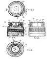
- FIG. 1is a front perspective view of a dispensing package showing the cover installed on the dispensing closure;
- FIG. 2is an exploded view of the dispensing closure and cover of FIG. 1 illustrating an aspect of the present invention
- FIG. 3is a top plan view of the closure and cover of FIG. 2 ;
- FIG. 4is a longitudinal sectional view taken along line 4 — 4 in FIG. 3 ;
- FIG. 5is a side elevational view of the dispensing package of FIG. 1 ;
- FIG. 6is a bottom plan view of the dispensing package of FIG. 2 ;
- FIG. 7is a top plan view of a prior art closure having a cross-shaped projection, which is shown in phantom;
- FIG. 8(PRIOR ART) is a cross sectional view of the closure shown in FIG. 7 .
- a conventional dispensing packageincludes a container 12 (shown schematically in FIGS. 7 and 8 ), a valved dispensing closure 14 , and a cover 101 , each of which is more fully described in U.S. Pat. No. 6,089,418, which is assigned to the present assignee
- the description FIGS. 7 and 8employs reference numerals not shown in FIGS. 7 and 8 , but which generally refer to analogous structure as shown in other figures and described in other portions of specification.
- the valved dispensing closure 14includes a self-sealing dispensing valve 16 , a base 30 , and a retaining ring 50 , as shown in FIGS. 7 and 8 , and in the lower portion of FIG.
- Valve 16comprises a one-piece, integrally-molded member preferably constructed from liquid silicone rubber, or the like. Valve 16 includes a concave valve head 18 with cross-slits 20 defining pie shaped flaps 22 and a discharge orifice therein. Cross-slits 20 and flaps 22 are best shown in FIG. 6 .
- a connector sleeve 24has one end connected with the marginal circumferentially extending flange 26 , which is substantially triangular in cross section, and the opposite end connected with valve head 18 adjacent to this marginal edge.
- Connector sleeve 24is resiliently flexible such that when pressure within bottle 12 is raised above a predetermined threshold value, connector sleeve is capable of deforming outwardly, as described more fully below.
- the valve head 18has a circular plan shape, and a generally tapered thickness which is thicker at the radially outside portion of valve head 18 and thinner at the radially inside portion thereof.
- connector sleeve 24Upon squeezing the sidewalls of container 12 such that bottle internal pressure is raised above a predetermined threshold value, connector sleeve 24 extends outwardly and valve head 18 shifts outwardly (that is, upward with respect to FIGS. 2 and 8 ). Flaps 22 open and unfold outwardly with a snapping action to permit product to be dispensed therethrough.
- the snap-type opening of valve 16is believed to be achieved in part by the torque exerted on valve head 18 by the connector sleeve 24 .
- the cross shaped projection of the cover disclosed in the U.S. Pat. No. 6,089,418, under certain conditions,may sometimes provide an imperfect inhibition against deformation of flaps 22 .
- the cross-shaped projectionsmay be directly aligned with the slits, may be positioned equidistant from the slits (that is, halfway between each slit), or may be positioned such that an edge of the cross-shaped projections are disposed on or slightly spaced apart from the slits.
- the covermight not, depending on the magnitude of the internal pressure, temperature, resilience of the flaps, and like parameters, inhibit the valve from inadvertently opening while the cover is in each of the above positions, including both latter positions, (which may provide the smallest degree of inhibition from opening), and either of the two former positions.
- the valved dispensing closure 14may also include base 30 , which includes a substantially cylindrical lower side wall 32 provided threads 34 for mating with corresponding threads (not shown) container 12 .
- the bottom of the side wall 32has a downwardly depending apron 36 having upwardly extending flanges 38 which are adapted to engage and lock under a radial rib (not shown) of the bottle neck when the closure 14 is initially applied to the neck of the bottle 12 .
- the bottom of the side wall 32is connected to the apron 36 through an interposed ruptureable line of weakening 40 , thereby providing a tamper evident feature.
- the base 30preferably includes a reduced diameter upper side wall 42 connected to the lower side wall 32 by a substantially horizontal ledge 44 .
- a circumferential sealing edge 46may be formed on the underside of ledge 44 to engage the top of the neck of the bottle 12 for sealing therebetween.
- Sealing edge 46preferably is sloped to form an angle of approximately five degrees from the horizontal so as to properly mate to a corresponding sealing surface on the lip of bottle 12 .
- an inner rim of the sealing edgeis lower than an outer portion of the sealing edge.
- sealing edge 46does not permanently deform when induction welded to the neck of the bottle, which improves over the “crab's claw” seal of other designs, which may occasionally deform, especially when induction welded to the bottle.
- Such deformation of the crab's claw designwhich may be permanent, may promote leakage, especially upon re-use after initially removing base 30 from bottle 12 .
- the interior of the upper side wall 42 of base 30includes a radially inwardly extending lip 48 and a substantially horizontal radially inwardly extending top 52 .
- the base top 52has an opening 82 for exposing the valve head 18 and connector sleeve 24 and for enabling the discharge of product from the valve 16 .
- a circumferential extending recess 53 bis formed on the underside of base top 52 substantially outside of opening 82 .
- lip 48is formed on the inner surface of base 30 below top 52 .
- Lip 48has an inner diameter that is smaller than an outer diameter of the lower rim of retaining ring 50 .
- a sloped portion lip 48provides a surface that contacts the lower rim of retaining ring 50 , which is secured and anchored between the sloped portion of the lip 48 and the lower portion of flange 26 . Lip 48 , therefore, receives and anchors in place of the retaining ring 50 .
- the retaining ring 50includes a circumferentially extending recess 53 a on its upper face and a circular projection 51 that extends downward from an inner portion of retaining ring 50 .
- Projection 51stiffens retaining ring and facilitates assembly by providing a datum surface that may be gripped or used to manipulate ring 50 into position within base 30 .
- the recess 53 a in the retaining ring and the recess 53 b in the baseare opposing to form a triangular cross sectional shape to correspond to the cross sectional shape of flange 26 .
- the triangular shapes of flange 26 and the corresponding recesses 53 a and 53 bprovide a clamping action while the valve 16 is actuated.
- the provision for clamping valve flange 26 internally within the base top 52 by the internally secured retaining ring 50is an important security and anti-tamper provision of the present invention.
- the bottle 12is preferably resiliently deformable and may be conveniently blow molded from one of many well known resins such as poly-propylene, polyethylene, polyvinyl, polyethylene terephthalate (PET) or the like.
- Bottle 12preferably exhibits a sufficient degree of flexibility to permit manual deformation by squeezing of the bottle side walls to extrude product through the valve dispensing closure 14 .
- the bottle 12preferably also exhibits a sufficiently strong bias or pre-disposition to return to its undeformed condition when external forces are removed so that a substantial, virtually instantaneous pressure drop will be generated within the bottle, thereby assisting the seal of the valved dispensing closure 14 in a manner to be described in detail.
- Cover 54extends around the upper side wall 42 and over the top 52 of base 30 and valve 16 , thereby protecting the closure 14 .
- Cover 54includes a downwardly depending substantially cylindrical skirt 56 that is adapted to slide tightly over and embrace the exterior of the upper side wall 42 .
- Cover 54also includes a top 58 that is formed at the upper end of skirt 56 .
- a lip 62is formed at the peripheral edge of the top 58 , which provides a gripping surface for a user to remove the cover from base 30 .
- Radial fins 57are provided on the exterior of skirt 56 to eliminate interlock with the tamper evident band of other similar closure.
- fins 57are oriented longitudinally on the cylindrical exterior of skirt 56 and yield into lip 62 . Fins 57 prevent cover 54 (especially lip 62 ) from interlocking or interfering with gaps formed in tamper evident bands of other closures when they are randomly loaded into a storage container and when introduced into closure assembly equipment. Further, fins 57 stiffen cover 54 around skirt 56 .
- the present inventionencompasses members that protrude from cover 54 having shapes other than longitudinally extending fins, including (for example) one or more circumferential flanges, spiral or helical fins, pin fins, and the like, as well as covers that lack such protrusions.
- Base 30may include features that cooperate with the cover 54 to provide a water tight seal.
- base 30includes a pair of circumferential ribs 59 a and 59 b disposed around the exterior of the lower portion of the upper sidewall 42 .
- a circumferential recess 49is formed in base 30 on ledge 44 at the base of upper sidewall 42 .
- the presentis not limited to covers and/or bases 30 that include ribs 59 a and 59 b and/or recess 49 .
- the present inventionencompasses covers that have shapes other than a cylindrical skirt and substantially flat top, including conical and curved sidewalls.
- the userWhen the user desires to dispense and use product from the bottle 12 , the user removes the protective cover 54 by urging upward against lip 62 .
- the bottle 12is inverted and the product contained within the bottle 12 may be dispensed by squeezing the bottle side walls to increase the internal pressure of the container until it exceeds a threshold value to effect shifting of the valve head 18 from an inwardly concave sealed position. Specifically, the increase in internal pressure urges outward against valve head 18 , which causes connector sleeve 24 to roll outward.
- valve head 18deforms such that flaps 22 open at slits 20 in response to a further increase in internal pressure of the bottle 12 .
- flaps 22snap open.
- valve head 18Upon release of the bottle sidewalls, the squeezing forces are released and the internal pressures are reduced. In response to the diminished internal bottle pressures, the valve head 18 returns toward its at-rest, inwardly curved, concave position. Preferably, the flaps 22 snap shut in response to the decrease in internal pressure, thereby shutting off flow of the product.
- the return processthat is, the return of valve 16 to its at-rest, sealed position
- valve 16quickly returns to its at-rest, sealed leak-proof position and the dispensing package can remain in its inverted position without fear or concern over leakage of product.
- cover 54 of the present inventionmay be assembled onto base 30 such that a lower-most circular edge 65 is insertable into recess 49 .
- the full insertion of cover 54 into recess 49corresponds to cover rib 63 being disposed between ribs 59 a and 59 b .
- a water tight sealmay be formed by the engagement of ribs 59 a and 59 b with the exterior of skirt 56 of cover 54 , and the engagement of rib 63 with the exterior surface of upper sidewall 42 .
- a water tight sealis formed by the engagement of edge 65 with recess 49 .
- Ribs 59 a and 63provide a snap that secures cover 54 onto base 30 , and its snapping or clicking together may provide an indication of positive sealing upon re-attaching the cover to the base by a user.
- cover 54may be placed around a portion of upper sidewall 42 , which is tapered.
- the inner diameter of the lower portion of cover 54may be sized to contact the lower, outer portion of sidewall 42 , and the contact may lightly hold cover 54 on base 30 .
- cover 54has an inner projection 68 and an outer projection 70 , each of which extends downwardly from the underside of top 58 .
- inner projection 68includes a thin post (that is, thin compared to the overall diameter of cover 54 ) that projects downwardly from top 58 at a longitudinal centerline thereof.
- Outer projection 70preferably is substantially concentric with inner projection 68 , and preferably forms a cylinder that has a circular transverse cross section.
- an outboard surface of each of projections 68 and 70form a circular cross section at their lower end.
- inner projection 68protrudes below outer projection 70 to correspond to the curvature of valve head 18 .
- the distal end of inner projection 68(that is, the end opposite top 58 ) is longitudinally disposed such that it lightly contacts the center or intersection of slits 20 and that it lightly contacts the tip of each of the flaps 22 .
- the distal tip of projection 70is radially and longitudinally disposed such that it lightly contacts the curved portion of valve head 18 and such that it is radially spaced apart from slits 20 .
- Outer projection 70may also lightly contact connector sleeve 24 , or projection 70 may contact connector sleeve 24 and be spaced apart from the concave portion of valve head 18 .
- projections 68 and 70extend into the cavity formed by valve head 18 while cover 54 is fully seated into recess 49 (that is, while cover 54 is attached to base 30 ). With cover 54 fully seated into recess 49 , the bottom tip of projection 68 contacts valve head 18 at its center at the intersection of the slits 20 , and projection 70 lightly contacts the sidewall portion of the valve head 18 and/or connector sleeve 24 . If the container is squeezed to increase its internal pressure while the cover 54 is fully inserted into recess 49 , the outer projection 70 prevents the outer portion of valve head 18 from inverting or extending outwardly, and inner projection 68 prevents the pie-shaped flaps 22 from opening.
- the present inventionalso encompasses projections 68 and 70 that are longitudinally spaced apart from valve head 18 , and which contact valve head 18 upon partial outward extension.
- the present inventionencompasses any contact, including for example, light contact, contact that displaces flaps 22 , and contact that occurs only upon outward movement of flaps 22 such that there is a gap formed between either or both projections 68 and 70 in the at-rest position.
- the projections 68 and 70prevent inadvertent actuation of the valve head 18 by preventing flaps 22 from opening because their tips are prevented from opening by projection 68 and by preventing valve head 18 from shifting from its concave position because valve head 18 and/or connector sleeve 24 is held by projection 70 .
- the present inventionillustrates an aspect of the present invention.
- the present inventionis not, however, limited to the particular configurations described above. Rather, the present invention encompasses any configuration of projection that extends downwardly to restrict the opening of flaps 22 , including, for example, for any configuration of projection 68 , only a projection (such as projection 68 ) disposed at the longitudinal centerline of the closure (that is, without projection 70 ), and other configurations that will be apparent to persons familiar with closures and/or flexible dispensing valves.
- the present inventionencompasses projections that form a conical shape having a circular transverse cross section, projections that form an oval or other non-circular shape, and projections that are discontinuous as viewed in transverse cross section (such as, for example, several posts or arc-like sections that together make up either an inner projection or outer projection and perform the functions thereof as described herein).
- the outer projectionencompasses downwardly projecting pins, as distinguished from a circular projection, that contact valve head 18 and/or connector sleeve 24 .
- the present inventionis not limited to the particular embodiment or configuration described herein, but, rather encompasses various modifications or variations, as will be understood by persons generally familiar with closure technology.
- the present inventionis not limited to any particular configuration of the valve, means of securing the cover to the valve, and the like.
- the scope of the inventionis determined by the appended claims.
Landscapes
- Engineering & Computer Science (AREA)
- Mechanical Engineering (AREA)
- Closures For Containers (AREA)
Abstract
Description
Claims (27)
Priority Applications (3)
| Application Number | Priority Date | Filing Date | Title |
|---|---|---|---|
| US10/098,819US6910607B2 (en) | 2002-03-15 | 2002-03-15 | Cover for dispensing closure with pressure actuated valve |
| MXPA03002321AMXPA03002321A (en) | 2002-03-15 | 2003-03-17 | Cover for dispensing closure with pressure actuated valve. |
| US11/169,133US20050269373A1 (en) | 2002-03-15 | 2005-06-28 | Cover for dispensing closure with pressure actuated valve |
Applications Claiming Priority (1)
| Application Number | Priority Date | Filing Date | Title |
|---|---|---|---|
| US10/098,819US6910607B2 (en) | 2002-03-15 | 2002-03-15 | Cover for dispensing closure with pressure actuated valve |
Related Child Applications (1)
| Application Number | Title | Priority Date | Filing Date |
|---|---|---|---|
| US11/169,133Continuation-In-PartUS20050269373A1 (en) | 2002-03-15 | 2005-06-28 | Cover for dispensing closure with pressure actuated valve |
Publications (2)
| Publication Number | Publication Date |
|---|---|
| US20030173379A1 US20030173379A1 (en) | 2003-09-18 |
| US6910607B2true US6910607B2 (en) | 2005-06-28 |
Family
ID=28039449
Family Applications (2)
| Application Number | Title | Priority Date | Filing Date |
|---|---|---|---|
| US10/098,819Expired - Fee RelatedUS6910607B2 (en) | 2002-03-15 | 2002-03-15 | Cover for dispensing closure with pressure actuated valve |
| US11/169,133AbandonedUS20050269373A1 (en) | 2002-03-15 | 2005-06-28 | Cover for dispensing closure with pressure actuated valve |
Family Applications After (1)
| Application Number | Title | Priority Date | Filing Date |
|---|---|---|---|
| US11/169,133AbandonedUS20050269373A1 (en) | 2002-03-15 | 2005-06-28 | Cover for dispensing closure with pressure actuated valve |
Country Status (2)
| Country | Link |
|---|---|
| US (2) | US6910607B2 (en) |
| MX (1) | MXPA03002321A (en) |
Cited By (17)
| Publication number | Priority date | Publication date | Assignee | Title |
|---|---|---|---|---|
| US20050269373A1 (en)* | 2002-03-15 | 2005-12-08 | Gaiser Ricky G | Cover for dispensing closure with pressure actuated valve |
| US20060037975A1 (en)* | 2002-04-25 | 2006-02-23 | Udo Suffa | Self-closing valve |
| US20060075773A1 (en)* | 2002-04-19 | 2006-04-13 | Petur Thors | Heat transfer tubes, including methods of fabrication and use thereof |
| US20060133886A1 (en)* | 2004-12-01 | 2006-06-22 | Jw Pet Company, Inc. | Shampooing brush |
| US20070181523A1 (en)* | 2004-03-05 | 2007-08-09 | Jaeckel Gerhard Franz K | Closure for a container that holds a free-flowing product |
| WO2008118302A1 (en)* | 2007-03-27 | 2008-10-02 | Liquid Molding Systems, Inc. | Dispensing valve with improved dispensing |
| US20100108724A1 (en)* | 2008-10-30 | 2010-05-06 | Gilbert Buchalter | Twist open/twist close Closure |
| RU2431587C2 (en)* | 2006-06-21 | 2011-10-20 | Сиквист Клоужерз Форин, Инк. | Dispensing system with discharge valve that has decreased-size extending outlet |
| USD720622S1 (en) | 2011-11-30 | 2015-01-06 | Tc Heartland Llc | Bottle with cap |
| USD728378S1 (en) | 2013-03-15 | 2015-05-05 | Tc Heartland Llc | Container |
| USD738732S1 (en) | 2011-11-30 | 2015-09-15 | Tc Heartland Llc | Bottle with cap |
| US20180029863A1 (en)* | 2016-07-29 | 2018-02-01 | Berry Plastics Corporation | Liquid dispenser |
| US20190161245A1 (en)* | 2017-11-27 | 2019-05-30 | Gateway Plastics, Inc. | Valve for a dispensing container |
| US10472140B2 (en) | 2014-01-31 | 2019-11-12 | Specialized Bicycle Components, Inc. | Water bottle with self-closing valve |
| US10518943B2 (en) | 2013-03-15 | 2019-12-31 | Tc Heartland Llc | Container with valve |
| US11390442B2 (en)* | 2017-12-06 | 2022-07-19 | Vitop Moulding S.R.L. | Delivering tap equipped with internal silicone valve with automatic closure with multiple liquid-sealing and tamper-preventing systems |
| US11634256B2 (en)* | 2018-12-13 | 2023-04-25 | Obrist Closures Switzerland Gmbh | Flow control insert |
Families Citing this family (7)
| Publication number | Priority date | Publication date | Assignee | Title |
|---|---|---|---|---|
| US7255250B2 (en)* | 2004-06-22 | 2007-08-14 | Owens-Illinois Closure Inc. | Dispensing closure, package and method of manufacture |
| US7398900B2 (en)* | 2005-01-28 | 2008-07-15 | Owens-Illinois Closure Inc. | Dispensing closure, package and method of manufacture |
| US8397957B2 (en) | 2010-01-06 | 2013-03-19 | Berry Plastics Corporation | Dispensing valve |
| US20120199118A1 (en)* | 2011-02-04 | 2012-08-09 | Piramal Critical Care, Inc. | Bottle closure with hinged seal |
| ES2546493T3 (en)* | 2011-05-04 | 2015-09-24 | Aptargroup, Inc. | Hole closure system for use with a drilling / filling / emptying tool |
| KR200488094Y1 (en)* | 2016-12-30 | 2018-12-12 | 씨제이제일제당 주식회사 | cap for container |
| MX2022003317A (en)* | 2019-09-20 | 2022-09-21 | Heinz Co Brands H J Llc | Container, closure, and methods for manufacture. |
Citations (27)
| Publication number | Priority date | Publication date | Assignee | Title |
|---|---|---|---|---|
| US1989714A (en) | 1930-09-23 | 1935-02-05 | Statham Noel | Self-sealing valve |
| US2684789A (en) | 1950-11-24 | 1954-07-27 | Injection Molding Company | Seal cap and dispensing nozzle for tubes or bottles |
| US2713953A (en) | 1952-05-08 | 1955-07-26 | American Sterilizer Co | Valved closure |
| US3856170A (en) | 1973-06-14 | 1974-12-24 | M Kessler | Snap-top bottle cap with safety pry-off |
| US4728006A (en) | 1984-04-27 | 1988-03-01 | The Procter & Gamble Company | Flexible container including self-sealing dispensing valve to provide automatic shut-off and leak resistant inverted storage |
| US4749108A (en) | 1986-12-19 | 1988-06-07 | The Procter & Gamble Company | Bimodal storage and dispensing package including self-sealing dispensing valve to provide automatic shut-off and leak-resistant inverted storage |
| US5025942A (en) | 1988-08-03 | 1991-06-25 | Societe De Conseils Et D'etudes Des Emballages S.C.E.E. | Device for hanging various accessories on a screw ring or endpiece of a container |
| US5115950A (en)* | 1991-01-14 | 1992-05-26 | Seaquist Closures A Divison Of Pittway Corporation | Dispensing closure with unitary structure for retaining a pressure-actuated flexible valve |
| US5213236A (en) | 1991-12-06 | 1993-05-25 | Liquid Molding Systems, Inc. | Dispensing valve for packaging |
| EP0555623A1 (en) | 1992-02-14 | 1993-08-18 | The Procter & Gamble Company | System comprising a container having a slit valve as a venting valve and a liquid contained in said container |
| US5271531A (en) | 1991-01-14 | 1993-12-21 | Seaquist Closures, A Division Of Pittway Corp. | Dispensing closure with pressure-actuated flexible valve |
| US5409144A (en) | 1991-12-06 | 1995-04-25 | Liquid Molding Systems Inc. | Dispensing valve for packaging |
| US5456374A (en) | 1994-09-19 | 1995-10-10 | Beck; Matthew R. | Tamper evident container closure |
| US5531363A (en) | 1994-06-10 | 1996-07-02 | Aptargroup, Inc. | Dispensing closure cartridge valve system |
| JPH08282703A (en) | 1995-04-11 | 1996-10-29 | Yoshino Kogyosho Co Ltd | Valve-equipped stopper |
| US5632420A (en)* | 1993-11-03 | 1997-05-27 | Zeller Plastik, Inc. | Dispensing package |
| US5642824A (en) | 1995-12-07 | 1997-07-01 | Aptargroup, Inc. | Closure with multiple axis bistable hinge structure |
| US5743443A (en) | 1995-05-17 | 1998-04-28 | Georg Menshen Gmbh & Co. Kg | Slit valve for closing off containers |
| US5897033A (en)* | 1997-06-20 | 1999-04-27 | Yoshino Kogyosho Co., Ltd. | Container having slit valve |
| US5927549A (en)* | 1998-03-20 | 1999-07-27 | Aptargroup, Inc. | Dispensing structure with frangible membrane for separating two products |
| US5927566A (en)* | 1996-07-11 | 1999-07-27 | Aptargroup, Inc. | One-piece dispensing system and method for making same |
| US5954237A (en)* | 1995-08-25 | 1999-09-21 | The Coca-Cola Company | Dispensing valve closure with inner seal |
| US5971232A (en)* | 1998-06-03 | 1999-10-26 | Aptargroup, Inc. | Dispensing structure which has a pressure-openable valve retained with folding elements |
| US6039224A (en)* | 1998-12-17 | 2000-03-21 | Aptar Group, Inc. | Multiple-orifice dispensing system with improved seal |
| US6089418A (en) | 1997-06-23 | 2000-07-18 | Crown Cork & Seal Technologies Corporation | Dispensing closure with pressure actuated valve |
| US6089411A (en)* | 1996-02-29 | 2000-07-18 | L'oreal | Dispensing head and unit for a product with a liquid-to-viscous consistency comprising a flow reducer, and method of manufacturing same |
| US6179166B1 (en)* | 1999-10-12 | 2001-01-30 | Seaquist Closures Foreign, Inc. | Rod-supportable hanging container |
Family Cites Families (2)
| Publication number | Priority date | Publication date | Assignee | Title |
|---|---|---|---|---|
| US6662977B2 (en)* | 2002-03-14 | 2003-12-16 | Bernard R. Gerber | Modular valve assembly and system with airtight, leakproof and shockproof closure for engagement in the neck of a container |
| US6910607B2 (en)* | 2002-03-15 | 2005-06-28 | Crown Cork & Seal Technologies Corporation | Cover for dispensing closure with pressure actuated valve |
- 2002
- 2002-03-15USUS10/098,819patent/US6910607B2/ennot_activeExpired - Fee Related
- 2003
- 2003-03-17MXMXPA03002321Apatent/MXPA03002321A/enactiveIP Right Grant
- 2005
- 2005-06-28USUS11/169,133patent/US20050269373A1/ennot_activeAbandoned
Patent Citations (30)
| Publication number | Priority date | Publication date | Assignee | Title |
|---|---|---|---|---|
| US1989714A (en) | 1930-09-23 | 1935-02-05 | Statham Noel | Self-sealing valve |
| US2684789A (en) | 1950-11-24 | 1954-07-27 | Injection Molding Company | Seal cap and dispensing nozzle for tubes or bottles |
| US2713953A (en) | 1952-05-08 | 1955-07-26 | American Sterilizer Co | Valved closure |
| US3856170A (en) | 1973-06-14 | 1974-12-24 | M Kessler | Snap-top bottle cap with safety pry-off |
| US4728006A (en) | 1984-04-27 | 1988-03-01 | The Procter & Gamble Company | Flexible container including self-sealing dispensing valve to provide automatic shut-off and leak resistant inverted storage |
| US4749108A (en) | 1986-12-19 | 1988-06-07 | The Procter & Gamble Company | Bimodal storage and dispensing package including self-sealing dispensing valve to provide automatic shut-off and leak-resistant inverted storage |
| US5025942A (en) | 1988-08-03 | 1991-06-25 | Societe De Conseils Et D'etudes Des Emballages S.C.E.E. | Device for hanging various accessories on a screw ring or endpiece of a container |
| US5271531A (en) | 1991-01-14 | 1993-12-21 | Seaquist Closures, A Division Of Pittway Corp. | Dispensing closure with pressure-actuated flexible valve |
| US5115950A (en)* | 1991-01-14 | 1992-05-26 | Seaquist Closures A Divison Of Pittway Corporation | Dispensing closure with unitary structure for retaining a pressure-actuated flexible valve |
| US5213236A (en) | 1991-12-06 | 1993-05-25 | Liquid Molding Systems, Inc. | Dispensing valve for packaging |
| US5377877A (en) | 1991-12-06 | 1995-01-03 | Liquid Molding Systems, Inc. | Dispensing valve for packaging |
| US5409144A (en) | 1991-12-06 | 1995-04-25 | Liquid Molding Systems Inc. | Dispensing valve for packaging |
| EP0555623A1 (en) | 1992-02-14 | 1993-08-18 | The Procter & Gamble Company | System comprising a container having a slit valve as a venting valve and a liquid contained in said container |
| US5390805A (en)* | 1992-02-14 | 1995-02-21 | The Procter & Gamble Company | System comprising a container having a slit valve as a venting valve and a liquid contained in said container |
| US5632420A (en)* | 1993-11-03 | 1997-05-27 | Zeller Plastik, Inc. | Dispensing package |
| US5531363A (en) | 1994-06-10 | 1996-07-02 | Aptargroup, Inc. | Dispensing closure cartridge valve system |
| US5456374A (en) | 1994-09-19 | 1995-10-10 | Beck; Matthew R. | Tamper evident container closure |
| JPH08282703A (en) | 1995-04-11 | 1996-10-29 | Yoshino Kogyosho Co Ltd | Valve-equipped stopper |
| US5743443A (en) | 1995-05-17 | 1998-04-28 | Georg Menshen Gmbh & Co. Kg | Slit valve for closing off containers |
| US5954237A (en)* | 1995-08-25 | 1999-09-21 | The Coca-Cola Company | Dispensing valve closure with inner seal |
| US5642824A (en) | 1995-12-07 | 1997-07-01 | Aptargroup, Inc. | Closure with multiple axis bistable hinge structure |
| US6089411A (en)* | 1996-02-29 | 2000-07-18 | L'oreal | Dispensing head and unit for a product with a liquid-to-viscous consistency comprising a flow reducer, and method of manufacturing same |
| US6112951A (en)* | 1996-07-11 | 2000-09-05 | Aptargroup, Inc. | One-piece dispensing system and method for making same |
| US5927566A (en)* | 1996-07-11 | 1999-07-27 | Aptargroup, Inc. | One-piece dispensing system and method for making same |
| US5897033A (en)* | 1997-06-20 | 1999-04-27 | Yoshino Kogyosho Co., Ltd. | Container having slit valve |
| US6089418A (en) | 1997-06-23 | 2000-07-18 | Crown Cork & Seal Technologies Corporation | Dispensing closure with pressure actuated valve |
| US5927549A (en)* | 1998-03-20 | 1999-07-27 | Aptargroup, Inc. | Dispensing structure with frangible membrane for separating two products |
| US5971232A (en)* | 1998-06-03 | 1999-10-26 | Aptargroup, Inc. | Dispensing structure which has a pressure-openable valve retained with folding elements |
| US6039224A (en)* | 1998-12-17 | 2000-03-21 | Aptar Group, Inc. | Multiple-orifice dispensing system with improved seal |
| US6179166B1 (en)* | 1999-10-12 | 2001-01-30 | Seaquist Closures Foreign, Inc. | Rod-supportable hanging container |
Cited By (30)
| Publication number | Priority date | Publication date | Assignee | Title |
|---|---|---|---|---|
| US20050269373A1 (en)* | 2002-03-15 | 2005-12-08 | Gaiser Ricky G | Cover for dispensing closure with pressure actuated valve |
| US7178361B2 (en)* | 2002-04-19 | 2007-02-20 | Wolverine Tube, Inc. | Heat transfer tubes, including methods of fabrication and use thereof |
| US20060075773A1 (en)* | 2002-04-19 | 2006-04-13 | Petur Thors | Heat transfer tubes, including methods of fabrication and use thereof |
| US20060037975A1 (en)* | 2002-04-25 | 2006-02-23 | Udo Suffa | Self-closing valve |
| US7681750B2 (en)* | 2004-03-05 | 2010-03-23 | Seaquist-Löffler Kunststoffwerk Gmbh | Closure for a container that holds a free-flowing product |
| US20070181523A1 (en)* | 2004-03-05 | 2007-08-09 | Jaeckel Gerhard Franz K | Closure for a container that holds a free-flowing product |
| US7837403B2 (en)* | 2004-12-01 | 2010-11-23 | J.W. Pet Company, Inc. | Shampooing brush |
| US20060133886A1 (en)* | 2004-12-01 | 2006-06-22 | Jw Pet Company, Inc. | Shampooing brush |
| RU2431587C2 (en)* | 2006-06-21 | 2011-10-20 | Сиквист Клоужерз Форин, Инк. | Dispensing system with discharge valve that has decreased-size extending outlet |
| WO2008118302A1 (en)* | 2007-03-27 | 2008-10-02 | Liquid Molding Systems, Inc. | Dispensing valve with improved dispensing |
| US20080237271A1 (en)* | 2007-03-27 | 2008-10-02 | Liquid Molding Systems, Inc. | Dispensing valve with improved dispensing |
| US8397956B2 (en) | 2007-03-27 | 2013-03-19 | Aptargroup, Inc. | Dispensing valve with improved dispensing |
| US20100108724A1 (en)* | 2008-10-30 | 2010-05-06 | Gilbert Buchalter | Twist open/twist close Closure |
| USD817175S1 (en) | 2011-11-30 | 2018-05-08 | Tc Heartland Llc | Bottle and cap |
| USD720622S1 (en) | 2011-11-30 | 2015-01-06 | Tc Heartland Llc | Bottle with cap |
| USD738732S1 (en) | 2011-11-30 | 2015-09-15 | Tc Heartland Llc | Bottle with cap |
| USD932902S1 (en) | 2011-11-30 | 2021-10-12 | Tc Heartland Llc | Bottle with cap |
| USD728378S1 (en) | 2013-03-15 | 2015-05-05 | Tc Heartland Llc | Container |
| USD863064S1 (en) | 2013-03-15 | 2019-10-15 | Tc Heartland Llc | Container |
| US10518943B2 (en) | 2013-03-15 | 2019-12-31 | Tc Heartland Llc | Container with valve |
| USD801827S1 (en) | 2013-03-15 | 2017-11-07 | Tc Heartland Llc | Container |
| USD945886S1 (en) | 2013-03-15 | 2022-03-15 | Tc Heartland Llc | Container |
| US10472140B2 (en) | 2014-01-31 | 2019-11-12 | Specialized Bicycle Components, Inc. | Water bottle with self-closing valve |
| US20180029863A1 (en)* | 2016-07-29 | 2018-02-01 | Berry Plastics Corporation | Liquid dispenser |
| US10392239B2 (en)* | 2016-07-29 | 2019-08-27 | Berry Plastics Corporation | Liquid dispenser |
| US20190161245A1 (en)* | 2017-11-27 | 2019-05-30 | Gateway Plastics, Inc. | Valve for a dispensing container |
| US10836541B2 (en)* | 2017-11-27 | 2020-11-17 | Gateway Plastics, Inc. | Valve for a dispensing container |
| US11377266B2 (en) | 2017-11-27 | 2022-07-05 | Silgan Specialty Packaging Llc | Valve for a dispensing container |
| US11390442B2 (en)* | 2017-12-06 | 2022-07-19 | Vitop Moulding S.R.L. | Delivering tap equipped with internal silicone valve with automatic closure with multiple liquid-sealing and tamper-preventing systems |
| US11634256B2 (en)* | 2018-12-13 | 2023-04-25 | Obrist Closures Switzerland Gmbh | Flow control insert |
Also Published As
| Publication number | Publication date |
|---|---|
| US20030173379A1 (en) | 2003-09-18 |
| MXPA03002321A (en) | 2004-10-29 |
| US20050269373A1 (en) | 2005-12-08 |
Similar Documents
| Publication | Publication Date | Title |
|---|---|---|
| US6910607B2 (en) | Cover for dispensing closure with pressure actuated valve | |
| US6089418A (en) | Dispensing closure with pressure actuated valve | |
| US5050754A (en) | Cap for a neck finish on a wide mouth container | |
| RU2388672C2 (en) | Drinks container | |
| US4709823A (en) | Tamper evident bottle or package closure | |
| US4487326A (en) | Carbonated beverage package | |
| CA1172607A (en) | Nondetachable resealable closure | |
| US6419101B1 (en) | Tear band closure | |
| US5450973A (en) | Tamper-evident closure apparatus | |
| US6032829A (en) | Container and closure package and method of making same | |
| CN108473237B (en) | closure | |
| US3278089A (en) | Spout-type container closure | |
| US6769575B1 (en) | Tamper evident plastic closure | |
| US7665637B2 (en) | Self-venting sports type closure | |
| JPH09183455A (en) | Lid made of plastic | |
| EP3887278B1 (en) | A spouted pouch provided with a closure device | |
| US6357628B1 (en) | Tamper evident plastic closure | |
| CA2049765A1 (en) | Tamper-evident cap for containers | |
| US6073809A (en) | Snap-on tamper evident closure with push-pull pour spout | |
| US6257432B1 (en) | Cap and container assembly | |
| EP2114788B1 (en) | Tamper evident closure | |
| US6431404B1 (en) | Tamper evident plastic closure | |
| US6070766A (en) | Tamper evident closure | |
| US6024255A (en) | Tamper evident closure with push-pull pour spout | |
| US6073810A (en) | Tamper-evident closure |
Legal Events
| Date | Code | Title | Description |
|---|---|---|---|
| AS | Assignment | Owner name:CROWN CORK & SEAL TECHNOLOGIES CORPORATION, ILLINO Free format text:ASSIGNMENT OF ASSIGNORS INTEREST;ASSIGNORS:GAISER, RICKY G.;HIERZER, VALENTIN;SIMPSON, ROBERT;REEL/FRAME:013024/0435 Effective date:20020607 | |
| AS | Assignment | Owner name:CROWN CORK & SEAL TECHNOLOGIES, ILLINOIS Free format text:RELEASE OF SECURITY INTEREST;ASSIGNOR:JPMORGAN CHASE BANK;REEL/FRAME:013798/0522 Effective date:20030226 | |
| AS | Assignment | Owner name:CITICORP NORTH AMERICA, INC., AS COLLATERAL AGENT, Free format text:SECURITY INTEREST;ASSIGNOR:CROWN CORK & SEAL TECHNOLOGIES CORPORATION;REEL/FRAME:013791/0846 Effective date:20030226 | |
| AS | Assignment | Owner name:CROWN OBRIST GMBH, SWITZERLAND Free format text:ASSIGNMENT OF ASSIGNORS INTEREST;ASSIGNOR:CROWN PACKAGING TECHNOLOGY, INC.;REEL/FRAME:017546/0384 Effective date:20051011 | |
| AS | Assignment | Owner name:CROWN PACKAGING TECHNOLOGY, INC., ILLINOIS Free format text:CHANGE OF NAME;ASSIGNOR:CROWN CORK & SEAL TECHNOLOGIES CORPORATION;REEL/FRAME:018291/0878 Effective date:20031103 Owner name:OBRIST CLOSURES SWITZERLAND GMBH, SWITZERLAND Free format text:CHANGE OF NAME;ASSIGNOR:CROWN OBRIST GMBH;REEL/FRAME:018291/0944 Effective date:20051223 Owner name:CROWN HOLDINGS, INC., PENNSYLVANIA Free format text:RELEASE BY SECURED PARTY;ASSIGNOR:CITICORP NORTH AMERICA, INC.;REEL/FRAME:018296/0067 Effective date:20051011 | |
| FPAY | Fee payment | Year of fee payment:4 | |
| FEPP | Fee payment procedure | Free format text:PAYOR NUMBER ASSIGNED (ORIGINAL EVENT CODE: ASPN); ENTITY STATUS OF PATENT OWNER: LARGE ENTITY | |
| REMI | Maintenance fee reminder mailed | ||
| LAPS | Lapse for failure to pay maintenance fees | ||
| STCH | Information on status: patent discontinuation | Free format text:PATENT EXPIRED DUE TO NONPAYMENT OF MAINTENANCE FEES UNDER 37 CFR 1.362 | |
| FP | Lapsed due to failure to pay maintenance fee | Effective date:20130628 | |
| AS | Assignment | Owner name:CROWN PACKAGING TECHNOLOGY, INC., ILLINOIS Free format text:RELEASE BY SECURED PARTY;ASSIGNOR:CITICORP NORTH AMERICA, INC.;REEL/FRAME:032449/0248 Effective date:20140314 |