US6910148B1 - Router and routing protocol redundancy - Google Patents
Router and routing protocol redundancyDownload PDFInfo
- Publication number
- US6910148B1 US6910148B1US09/733,284US73328400AUS6910148B1US 6910148 B1US6910148 B1US 6910148B1US 73328400 AUS73328400 AUS 73328400AUS 6910148 B1US6910148 B1US 6910148B1
- Authority
- US
- United States
- Prior art keywords
- card
- standby
- routing protocol
- active
- controller system
- Prior art date
- Legal status (The legal status is an assumption and is not a legal conclusion. Google has not performed a legal analysis and makes no representation as to the accuracy of the status listed.)
- Expired - Lifetime, expires
Links
- 230000008859changeEffects0.000claimsabstractdescription76
- 230000003362replicative effectEffects0.000claimsabstractdescription10
- 238000000034methodMethods0.000claimsdescription33
- 230000003287optical effectEffects0.000claimsdescription3
- 230000015556catabolic processEffects0.000abstractdescription9
- 238000006731degradation reactionMethods0.000abstractdescription9
- 230000002085persistent effectEffects0.000description62
- 230000015654memoryEffects0.000description21
- 238000010586diagramMethods0.000description16
- 238000004891communicationMethods0.000description15
- 238000012546transferMethods0.000description11
- 230000008569processEffects0.000description10
- 230000003993interactionEffects0.000description9
- 230000006870functionEffects0.000description6
- 230000010076replicationEffects0.000description6
- 238000012545processingMethods0.000description5
- 230000003068static effectEffects0.000description5
- 230000000644propagated effectEffects0.000description4
- 230000005540biological transmissionEffects0.000description3
- 230000001788irregularEffects0.000description3
- 230000007246mechanismEffects0.000description3
- 230000001360synchronised effectEffects0.000description3
- 238000012360testing methodMethods0.000description3
- 238000012795verificationMethods0.000description3
- 238000003491arrayMethods0.000description2
- 230000003139buffering effectEffects0.000description2
- 230000006855networkingEffects0.000description2
- 230000002688persistenceEffects0.000description2
- 230000011218segmentationEffects0.000description2
- 238000006424Flood reactionMethods0.000description1
- 230000009471actionEffects0.000description1
- 230000006399behaviorEffects0.000description1
- 230000008901benefitEffects0.000description1
- 230000000903blocking effectEffects0.000description1
- 238000012790confirmationMethods0.000description1
- 230000008878couplingEffects0.000description1
- 238000010168coupling processMethods0.000description1
- 238000005859coupling reactionMethods0.000description1
- 230000000593degrading effectEffects0.000description1
- 238000013461designMethods0.000description1
- 238000001514detection methodMethods0.000description1
- 230000000694effectsEffects0.000description1
- 238000007726management methodMethods0.000description1
- 238000012986modificationMethods0.000description1
- 230000004048modificationEffects0.000description1
- 230000002093peripheral effectEffects0.000description1
- 238000011084recoveryMethods0.000description1
- 238000002553single reaction monitoringMethods0.000description1
- 238000013426sirius red morphometryMethods0.000description1
- 239000013598vectorSubstances0.000description1
Images


Classifications
- H—ELECTRICITY
- H04—ELECTRIC COMMUNICATION TECHNIQUE
- H04L—TRANSMISSION OF DIGITAL INFORMATION, e.g. TELEGRAPHIC COMMUNICATION
- H04L45/00—Routing or path finding of packets in data switching networks
- H04L45/02—Topology update or discovery
- H04L45/04—Interdomain routing, e.g. hierarchical routing
- H—ELECTRICITY
- H04—ELECTRIC COMMUNICATION TECHNIQUE
- H04L—TRANSMISSION OF DIGITAL INFORMATION, e.g. TELEGRAPHIC COMMUNICATION
- H04L45/00—Routing or path finding of packets in data switching networks
- H—ELECTRICITY
- H04—ELECTRIC COMMUNICATION TECHNIQUE
- H04L—TRANSMISSION OF DIGITAL INFORMATION, e.g. TELEGRAPHIC COMMUNICATION
- H04L45/00—Routing or path finding of packets in data switching networks
- H04L45/50—Routing or path finding of packets in data switching networks using label swapping, e.g. multi-protocol label switch [MPLS]
- H—ELECTRICITY
- H04—ELECTRIC COMMUNICATION TECHNIQUE
- H04L—TRANSMISSION OF DIGITAL INFORMATION, e.g. TELEGRAPHIC COMMUNICATION
- H04L45/00—Routing or path finding of packets in data switching networks
- H04L45/56—Routing software
- H—ELECTRICITY
- H04—ELECTRIC COMMUNICATION TECHNIQUE
- H04L—TRANSMISSION OF DIGITAL INFORMATION, e.g. TELEGRAPHIC COMMUNICATION
- H04L69/00—Network arrangements, protocols or services independent of the application payload and not provided for in the other groups of this subclass
- H04L69/40—Network arrangements, protocols or services independent of the application payload and not provided for in the other groups of this subclass for recovering from a failure of a protocol instance or entity, e.g. service redundancy protocols, protocol state redundancy or protocol service redirection
Definitions
- the present inventionpertains to the field of networking and networking devices. More particularly, the present invention relates to network routers and routing protocols. Specifically, the present invention relates to router and routing protocol redundancy.
- a networkis a collection of interconnected devices, which allow users to access resources and data. Common types of network devices include servers, routers, bridges, switches, gateways, and hubs.
- a well-known networkis the Internet.
- the Internetis a worldwide system of interconnected networks that runs the Internet Protocol (IP) to transfer data (e.g., packets). Because a packet can reach its destination by crossing a number of network boundaries on the Internet, IP includes a layer “ 3 ” service that provides routing and forwarding functions so that the packet can reach its destination using an optimal path.
- IPInternet Protocol
- a common network device that provides IP layer 3 serviceis a router.
- a routerroutes packets by determining an optimal path based on its current view of the network and forwards the packet across the network boundaries to a destination using the optimal path. Based on its view of the network, a router generates and maintains a routing table of available routes known to the router. The router uses the routing table to create a forward information table (FIB).
- the FIBis a table of routes that the router uses to forward packets to their destination.
- a routeruses a routing protocol to exchange information with other routers in order to maintain a consistent view of the network (i.e., a consistent FIB). For packets to be forwarded properly, each router must have a consistent FIB with other routers on the network. That is, routers having inconsistent forwarding information tables (FIBs) will not traverse packets through the network in a predictable manner. As such, routing loops or improper routing of packets can occur.
- FIBsforwarding information tables
- a router failurecan fail for any number of reasons such as misconfigurations, hacker attacks, hardware failures, and software failures. Such failures are unpredictable.
- a router failurecan cause the topology of the network to change. In particular, the topology can change because certain links or routes disappear.
- routing protocol informationcan be lost because certain nodes cannot be reached or certain information cannot be propagated throughout the network.
- packetsmay be unable to reach a destination because certain addresses are unreachable.
- a router failurecan thus cause a number of problems such as a service outage, service degradation (suboptimal routing), and service outage due to large routing table convergence time.
- a failed routercan cause other routers to forward packets using non-optimal paths causing service degradation because the packets may take more time to reach their destination.
- a failed routerwill also cause its peers and other routers on the network through these peers to update their routing tables (“convergence”) causing a service outage or degradation to perform such a convergence.
- a routerfails and routing protocols of peer nodes or neighboring routers observe the failure, the routing protocols will propagate knowledge of the failed router throughout the network so that the routing tables are updated accordingly. Consequently, before the network can resume complete services, there is a service outage or degradation to update the routing tables in the working routers so they can generate consistent FIBs with each other. This network reconfiguration can take several seconds, minutes, or hours before the entire network can recover. For mission critical services, such a behavior is unacceptable.
- a method for dealing with a router failureis to have hardware redundancy in order to increase system availability.
- This type of redundancyis commonly referred to as layer 2 redundancy.
- a layer 2 redundancy systemmay include redundant line cards, ports, or controller cards. If a line card, port, or controller card fails, the redundant line card, port, or controller card can resume operation.
- a disadvantage of layer 2 redundancyis that it does not provide realtime routing protocol redundancy. For instance, the numerous software states that are generated by the routing protocols in realtime are not maintained in the redundant hardware causing protocol sessions to be dropped. Therefore, in a layer 2 redundancy system, protocol sessions are dropped causing a network topology change and thus a service outage or service degradation.
- VRRPVirtual Router Redundancy Protocol
- a router and routing protocol redundancyare disclosed to reduce service outage or degradation for a network device and thus to increase service availability on a network due to software and hardware failures of the network device.
- a network devicesuch as router includes a redundancy platform having an active controller system and a standby controller system.
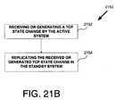
- a routing protocol state changeis received or generated by the active controller system.
- the received or generated routing protocol state changeis replicated to the standby controller system.
- the standby controller systemcan maintain the routing protocol sessions for the network device if a failure occurs in the active controller system.
- the routing protocol statesare maintained in realtime to handle the dynamic changes created by routing protocols.
- FIG. 1illustrates an exemplary network in which the present invention can be practiced
- FIG. 2illustrates an architecture layered model that can be used by the nodes shown in FIG. 1 according to one embodiment
- FIG. 3illustrates a flow chart of a basic operation for a redundant node according to one embodiment
- FIG. 4Aillustrates a diagram to show replication of routing protocol information from an active card to a standby card
- FIG. 4Billustrates a flow chart of an operation for replicating routing protocol state change information according to one embodiment
- FIG. 5illustrates a flow chart of a detailed operation for the resuming operation in FIG. 3 having a fast switchover to the standby controller system according to one embodiment
- FIG. 6Aillustrates a diagram to show spoofing of a peer node from observing a failure and a switchover according to one embodiment
- FIG. 6Billustrates a diagram to show spoofing of a peer node from observing a failure and a switchover according to another embodiment
- FIG. 7illustrates a flow chart of an operation for sending a commit to a peer node according to one embodiment
- FIG. 8illustrates a network device having an active controller system and a standby controller system according to one embodiment
- FIG. 9illustrates a redundancy platform for a network device according to one embodiment
- FIG. 10Aillustrates a flow chart of an operation for a boot sequence according to one embodiment
- FIG. 10Billustrates a flow chart of an operation for a boot sequence according to another embodiment
- FIGS. 11A and 11Billustrate a flow chart of an operation for an active card to perform a graceful switchover to a standby card according to one embodiment
- FIGS. 12A and 12Billustrate a flow chart of an operation for a standby card to perform the graceful switchover according to one embodiment
- FIG. 13illustrates a flow chart of an operation for a standby card to perform a non-graceful switchover according to one embodiment
- FIG. 14illustrates a flow chart of an operation to update persistent information to a standby card according to one embodiment
- FIG. 15illustrates a flow chart of an operation to update non-persistent information to a standby card according to one embodiment
- FIG. 16illustrates a flow chart of an operation to perform error handling according to one embodiment
- FIG. 17illustrates a diagram to show routing protocol interaction within a network device according to one embodiment
- FIG. 18illustrates a diagram to show routing protocol interaction between an active card and a standby card according to one embodiment
- FIG. 19illustrates an architecture for routing protocol redundancy according to one embodiment
- FIG. 20illustrates an exemplary diagram to show an interaction between BGP, TCP, and IP.
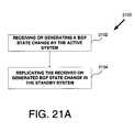
- FIG. 21Aillustrates a flow chart of an operation for replicating received or generated BGP state changes according to one embodiment
- FIG. 21Billustrates a flow chart of an operation for replicating received or generated TCP state changes according to one embodiment
- FIG. 22illustrates one embodiment of a dialog between an active TCP operating on an active card and a standby TCP operating on a standby card to show a lock step requirement for a BGP message being sent to a peer node;
- FIG. 23illustrates one embodiment of a dialog between an active TCP operating on an active card and a standby TCP operating on a standby card to show a lock step requirement for a BGP message being received from a peer node;
- FIG. 24illustrates a BGP architecture to show delta updating for individual BGP information being sent to a peer node according to one embodiment
- FIG. 25illustrates a BGP architecture to show delta updating for individual BGP information being sent to a peer node according to one embodiment
- FIG. 26illustrates a BGP architecture to show delta updating for individual BGP information being received from a peer node according to one embodiment
- FIG. 27illustrates a flow chart to commit to a BGP message according to one embodiment
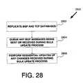
- FIG. 28illustrates a flow chart of an operation to perform bulk updating for the BGP protocol redundancy according to one embodiment
- FIG. 29illustrates a flow chart of an operation to perform bulk updating for the IS-IS protocol redundancy according to one embodiment.
- FIG. 30illustrates a flow chart of an operation to perform delta updating for the IS-IS messages being received or sent according to one embodiment
- FIG. 31illustrates a flow chart of an operation to perform bulk updating for the OSPF according to one embodiment
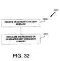
- FIG. 32illustrates a flow chart of an operation to perform delta updating for the OSPF messages being received or sent according to one embodiment.
- a router and routing protocol redundancyare described to reduce service outage or degradation for a network device and thus to increase service availability on a network due to software and hardware failures of the network device.
- a network devicesuch as a router includes a redundancy platform having an active controller system and a standby controller system.
- a routing protocol state changeis received or generated by the active controller system.
- the received or generated routing protocol state changeis replicated to the standby controller system.
- the standby controller systemcan maintain the routing protocol sessions for the network device if a failure occurs in the active controller system.
- the routing protocol statesare maintained in realtime to handle the dynamic changes created by routing protocols.
- the redundancy techniques described hereinallow a failed network device to return to service in a short amount of time to avoid service outages.
- the redundancy techniquesalso allow a backup or standby controller system to return the failed network device to service at the working state of the active controller system prior to a failure.
- the redundancy techniquesalso prevent peer nodes to a network device from observing the failure to the network device.
- the redundancy techniquesalso prevent routing protocol sessions from being dropped in the event of a switchover from an active controller system to a standby controller system by maintaining the protocol sessions in realtime.
- the redundancy techniquesalso maintain a consistent view of the network in a standby controller system.
- redundancy techniquesare described with respect to network routers and routing protocols.
- the redundancy techniques described hereinare not intended to be limited to any particular type of network device and can be implemented with other types of network devices, which can have hardware and software failures or perform routing protocol functions such as, for example, network switches, network optical switches, bridges, hubs, or gateways.
- router redundancyrefers to a router having a backup controller system (i.e., standby controller system) for an active controller system.
- the standby controller systemcan resume operation for the active controller system if the active controller system fails.
- routing protocol redundancyrefers to maintaining protocol sessions running on the active controller system in the standby controller system and to maintaining consistent routing and forwarding information in the standby controller system with the active controller system.
- FIG. 1illustrates an exemplary network 100 in which the present invention can be practiced.
- exemplary network systemincludes a node 104 having a redundancy platform 900 (“redundant node 104 ”) interconnected with a plurality of peer nodes 102 A and 102 B.
- redundancy platform 900redundancy platform 900
- network 100can include any number of nodes.
- Peer nodes 102 A and 102 Bare nodes having a “session” or “logical connection” with redundant node 104 .
- nodes 102 A, 102 B, and redundant node 104represent network devices such as, for example, network routers performing IP layer 3 services.
- nodes 102 A, 102 B, and redundant node 104can be other type of network devices such as, for example, switches, bridges, hubs, or gateways that can perform IP layer 3 services or even higher layer level services up to application services.
- the nodes 102 A, 102 B, and redundant node 104can perform Multiprotocol Label Switching (MPLS) services.
- MPLSMultiprotocol Label Switching
- Nodes 102 A, 102 B, and redundant node 104can represent network routers that are used to forward information (i.e., packets) through one particular group of networks under the same administrative authority and control, which is commonly referred to as an Autonomous System (AS).
- ASAutonomous System
- nodes 102 A, 102 B, and redundant node 104can represent “Interior Routers” that run an Interior Gateway Protocol (IGPs) to exchange information within the AS.
- IGPsInterior Gateway Protocol
- nodes 102 A, 102 B, and redundant node 104can operate routing protocols such as an Intermediate System-to-Intermediate System Protocol (IS-IS), Open Shortest Path First Protocol (OSPF), and a Routing Information Protocol (RIP).
- IS-ISIntermediate System-to-Intermediate System Protocol
- OSPFOpen Shortest Path First Protocol
- RIPRouting Information Protocol
- the IS-IS protocol and the OSPF protocolare link state protocols.
- a link state protocoluses link state packets to maintain a consistent view of the network.
- the RIP protocolis a simple protocol based on distance vectors that use a shortest path computation.
- nodes 102 A, 102 B, and 104can represent network routers that are used to forward information between ASs in which case the routers are referred to as “Exterior Routers” and run Exterior Gateway Protocols (EGPs). If acting as EGPs, node 102 A, 102 B, and redundant node 104 can operate a routing protocol such as a Border Gateway Protocol (BGP). The BGP protocol exchanges connectivity information over a reliable transport protocol such as the Transport Control Protocol (TCP) and does not have error control capabilities.
- Nodes 102 A, 102 B, and redundant node 104can represent any combination of Interior Routers or Exterior Routers and any number of routers can be represented within network 100 .
- nodes 102 A, 102 B, and redundant node 104can maintain consistent routing and routing protocol state information. If a route is updated, the route must be updated in peer nodes to maintain a consistent view of the network. For one embodiment, nodes 102 A, 102 B, and redundant node 104 can determine neighbors by sending out a “hello” packet. If an established peer node does not respond to the “hello” packet in a certain period of time, the peer node will considered to be inoperative or have “failed.”
- redundant node 104is a special type of node having a redundancy platform with an active controller system (active card 910 ) and a standby controller system (standby card 950 ) that can prevent failures in the node from being observed by peer nodes 102 A and 102 B. Furthermore, if the active controller system fails, the standby controller system can resume protocol sessions with peer nodes such that the peer nodes do not observe that the active controller system failed.
- node 102 Asends a “hello” packet to redundant node 104 , that is lost for any reason, and switchover occurs, and node 102 A resends the hello packet, the standby controller system can resume operation for redundant node 104 and acknowledge the resent hello packet before a timeout period. Thus, node 102 A does not observe the switchover to the standby system.
- node 104represents a router having a redundancy platform 900 as shown in FIG. 9 .
- the redundancy platform 900includes an active card 910 and a standby card 950 to resume operation if there is a failure to the active card 910 .
- the active card 910 and standby card 950include hardware and software modules operating therein.
- both active card 910 and standby card 950can run potentially different or the same versions of software.
- the redundancy platform 900provides the support to have router and routing protocol redundancy for node 104 , which prevents peer nodes from observing failures and maintains routing protocol sessions for the redundant node 104 with its peer nodes.
- FIG. 2illustrates an architecture layered model 200 that can be used by the nodes shown in FIG. 1 according to one embodiment
- the active card 910 and standby card 950operate using the architecture layered model 200 .
- the architecture layered model 200can be based on a standard 7 -layer reference model for network communications.
- architecture layered model 200represents one embodiment of the different layers in which an IP router can operate.
- architecture layered model 200includes a physical layer 202 , link layer 204 , IP layer 206 , Transmission Control Protocol (TCP) layer 208 , User Datagram Protocol (UDP) layer 208 , Internet Control Message Protocol (ICMP) 218 , routing protocols layer 220 that includes a Border Gateway Protocol (BGP) layer 226 , Routing Internet Protocol (RIP) layer 222 , Open Shortest Path First (OSPF) protocol layer 224 , Intermediate System-to-Intermediate System (IS-IS) protocol layer 214 , sockets layer 210 , applications layer 212 .
- the routing protocols 220can maintain a routing table to generate a forwarding information table (FIB) 216 .
- the FIB 216is used by the IP layer 209 and link layer 216 .
- the above layersprovide services for nodes in a network.
- the physical layer 202provides the service of moving data between nodes on a physical link.
- the link layer 204provides the service of handling the data being transferred on the physical link.
- the IP layer 209(“IP layer 3 ”) provides routing and forwarding services over the physical and link layers.
- IP layer 3(“IP layer 3 ”) provides routing and forwarding services over the physical and link layers.
- the TCP layer 208provides the service of ensuring complete data transfer by performing error-checking and making sure all data has arrived.
- the TCP layer 208operates over the IP layer 3 .
- nodes in a networkcan transmit data using a TCP service over an IP layer 3 service.
- the ICMP layer 218runs on top and is an integral part of IP layer 206 . That is, IP layer 3 service is inherently unreliable and data packets can be dropped. Thus, the ICMP layer 218 provides message control and error-reporting for the IP layer 3 service.
- the UDP layer 209provides an alternative service to the service provided by the TCP layer 208 . In particular, the UDP layer 209 runs on top of the IP layer 3 service layer to provide a connectionless transmission protocol for transmitting datagrams. That is, the UDP layer 209 does not provide end-to-end error detection.
- the sockets layer 210provides an end-point of a two-way communication between applications layer 212 or routing protocols 220 of a node running on a network.
- the applications layer 212includes applications running on a node. The applications layer 212 can use the lower layers to communicate with applications of other nodes.
- the routing protocols 220provide the service of determining optimal paths (“routes”), forwarding packets, and ensuring updates to the routes are consistent throughout the network. By analyzing routing updates from all routers, a router can build detailed view of the network. Within routing protocols 220 , a number of routing protocols can operate. For example, the BGP protocol 226 , RIP protocol 222 , OSPF protocol 224 , and the IS-IS protocol 220 can all operate within the routing protocols layer 220 . The routing protocols 220 can use FIB 216 for the transmission of data (e.g., packets) within the layer 3 service provided by the IP layer 206 .
- datae.g., packets
- the BGP protocol 226is not a reliable routing protocol. Thus, BGP 226 runs on top of TCP 208 for reliable transfer of messages or packets. In particular, BGP 226 does not resend messages or packets, but relies on the TCP 208 to handle lost messages or packets.
- RIP 222uses UDP 209 for the transfer of messages or packets.
- OSPF 224 and IS-IS 214have reliable data transfer mechanisms within their respective routing protocols. OSPF 224 runs on top of IP layer 206 and IS-IS 214 runs directly on top of the link layer 204 .
- routing protocols operating in redundant node 104can operate in conjunction with the redundancy platform 900 to obtain router and routing protocol redundancy.
- the redundancy platform 900provides the support necessary to have realtime routing protocol redundancy. That is, routing protocols are dynamic in which updates to routes occur at regular or irregular intervals depending on routing protocols. To have full redundancy, these updates need to be maintained in realtime.
- the routing protocol sessions states for RIP 222 , OSPF 224 , BGP 226 , and IS-IS 214 that may be running on the active card 910 for redundant node 104can be maintained in realtime on the standby card 950 using the redundancy platform 900 .
- the standby card 950can resume same routing protocol session states if the active card 910 fails.
- FIB 216is also maintained in the standby card 950 such that the standby card 950 will have the most current view of the network if it takes over control for the redundant node 104 .
- FIG. 3illustrates a flow chart of a basic operation 300 for redundant node 104 according to one embodiment.
- the following operation 300can be implemented by redundant node 104 having an active card 910 and standby card 950 as shown in FIG. 1 .
- redundant node 104is a network router 104 that can perform IP layer 3 or MPLS services and operation 300 begins at operation 302 .
- redundant node 104maintains the current state of the active card 910 in the standby card 950 .
- redundant node 104uses the redundancy platform 900 to replicate or copy current configuration information, global information, routing table information, forwarding table information, protocol session information, or database information in the active card 910 to the standby card 950 .
- the active card 910detects a failure.
- the active card 910can detect a hardware failure or a software failure in redundant node 104 that will cause redundant node 104 to switchover operation from active card 910 to standby card 950 .
- the standby card 950will resume operation of the current state of the active card 910 prior to failure.
- the standby card 950will resume operation such that the failure is not observed by peer nodes 102 A or 102 B.
- redundant node 104can prevent failures from being observed by the peer nodes by maintaining in realtime routing protocol session states of the active card 910 in the standby card 950 and by obtaining a fast switchover to the standby card 950 such that a protocol session will not be dropped.
- a network topology changedoes not have to be propagated throughout the network and convergence time is reduced.
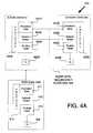
- FIG. 4Aillustrates a diagram 400 to show replication of routing protocol information from active card 910 to standby card 950 .
- the redundancy platform 900provides the support to maintain routing protocol information protocol in realtime in standby card 950 .
- the diagramshows peer node 102 A communicating with redundant node 104 .
- the redundant node 104includes a redundancy platform 900 having an active card 910 communicating with peer node 102 A.
- the redundant node 104also includes a standby card 950 to resume operation if there is a failure to active card 910 .
- peer node 102 Aincludes protocol information 415 including persistent data 411 , session states 412 , and routing table 413 , which is used to generate the FIB 432 .
- the protocol information 415must be consistent with the protocol information 405 A within active card 910 . That is, the persistent data 411 , session states 412 , and routing table 413 information of peer node 102 A must be consistent with persistent data 401 A, session states 402 A, and routing table 403 A so that standby card 950 can be replicated with the same information to ensure redundancy.
- the routing tables 413 and 403 Aare not consistent, the FIB 432 in peer node 102 A will not be consistent with the FIB 422 A in active card 910 .
- peer node 102 Amay consider redundant node 104 to have a different view of the network that it has and peer node 102 A and can tear down routing protocol sessions with redundant node 104 .
- changes received or made by active card 910 to protocol information 405 Amust be replicated to protocol information 405 B in standby card 950 .
- changes received or made by active card 910 to persistent data 401 A, session states 402 A, and routing table 403 Aare replicated to persistent data 401 B, session states 402 B, and routing table 403 B in standby card 950 . If the changes are not maintained, redundancy is broken.
- the protocol informationcan be related to routing protocols such as, for example, the BGP, RIP, OSPF, and IS-IS routing protocols.
- Persistent datacan include configuration information for each routing protocol that are more permanent in nature.
- Session state informationinclude routing protocol state changes for each routing protocol running on a node. Session state information is dynamic in nature and can change at regular or irregular intervals.
- routing protocol state change datacan include information related to rules for communication between nodes, status of every route received from a peer, status of every route sent to a peer, time out parameters, history of routes being deleted by every peer, and etc., for each routing protocol.
- Routing table informationincludes routes known by a node for each routing protocol. The routing table information is used to generate the FIB table, which is used to forward packets.
- the standby card 950is populated with pertinent information required for each routing protocol running on the active card 910 , if a failure occurs to the active card 910 , the standby card 950 can resume the routing protocol sessions of the active card 910 using a consistent FIB with the active card 910 . Thus, standby card 950 can resume the same protocol sessions using the same states of the active card 910 . In such a case, peer node 102 A will communicate with standby card 950 believing it is still communicating with active card 910 thereby avoiding a service outage.
- FIG. 4Billustrates a flow chart of an operation 450 for replicating routing protocol state change information according to one embodiment.
- the following operation 450can be implemented by redundant node 104 having an active card 910 and standby card 950 as shown in FIG. 1 .
- redundant node 104is a network router 104 performing IP layer 3 or MPLS services and operation 450 begins at operation 452 .
- routing protocol state change informationis received or generated by active card 910 .
- active card 910can generate a change to persistent data 401 A, session states 402 A, and routing table 403 A.
- active card 910can receive a change from peer node 102 A for persistent data 401 A, session states 402 A, and routing table 403 A
- the received or generated routing protocol state change in the active card 910is replicated to the standby card 950 .
- the redundancy platform 900 as shown in FIG. 9provides the support for the replication of persistent data 401 A, session states 402 A, and routing table 403 A in active card 910 to be made in its peer persistent data 401 B, session states 402 B, and routing table 403 B in standby card 950 .
- Such a replication operationis performed in realtime.
- standby card 950can resume operation using the same information in active card 950 .
- FIGS. 5 through 7illustrate how a node with redundancy platform 900 can prevent peer nodes from observing failures and switchovers.
- a standby controller systemstandby card 950
- the switchoveris fast enough (e.g., within a few milliseconds) that peer nodes do not observe that the redundant node 104 may have lagged slightly to perform the switchover.
- FIG. 5illustrates a flow chart of a detailed operation 306 of FIG. 3 for resuming operation by a standby controller system having a fast switchover according to one embodiment.
- operation 306begins at operation 502 .
- redundant node 104performs a switchover from active card 910 to standby card 950 .
- the switchovercan be performed within a few milliseconds.
- the small amount of time to perform the switchoveri.e., “glitch” is so small that a peer node 102 A does not observe that a switchover has occurred.
- the standby card 350resumes operation with peer node 102 A without bringing down a protocol session. That is, the glitch is so small that peer node 102 A does know there was a glitch in redundant node 104 .
- IPis inherently unreliable
- packetscan be dropped. If a packet is received by active card 910 from peer node 102 A and a failure occurs such that the active card 910 does not acknowledge receipt of the packet, peer node 102 A can resend the packet. In this situation even if there is a switchover, the standby card 950 can still receive the packet being resent from peer node 102 A and acknowledge receipt of that packet. Thus, the peer node 102 A will observe a common occurrence (i.e., resending a packet and receiving an acknowledgement to the resent packet) and will not believe a failure or switchover occurred in redundant node 104 even though a packet was dropped.
- the standby card 950can resume operation for the redundant node 104 without a routing protocol session from being torn down.
- each routing protocolincludes a timeout period in which it will tear down a session if a certain number of packets are not acknowledged within a certain period of time. Consequently, even if some packets are dropped during the switchover, the glitch is short for redundant node 104 having the redundancy platform 900 . That is, standby card 950 can resume operation for the active card 910 without sessions being torn down or services failing for redundant node 104 .
- FIG. 6Aillustrates a diagram 600 to show spoofing of a peer node from observing a failure and a switchover according to one embodiment.
- a peer node 102 A to redundant node 104requires that a transaction being committed by active card 910 be also committed by standby card 950 .
- the routing updatemust also be made in standby card 950 .
- peer node 102 Awill tear down its session with redundant node 104 because standby card 950 will not have a consistent view of the network as peer node 102 A.
- standby card 950did not commit to the update.
- Redundant node 104 having a redundancy platform 900can perform such a fast switchover and commit to transactions in the standby card 950 in preventing a peer node 102 A from tearing down protocol sessions.
- the diagramillustrates an active card 910 receiving a message (MSG A) from a peer node.
- the messagecan be, for example, to inform redundant node 104 that node 102 B has failed and that its route to 102 B must be updated accordingly.
- Node 102 Aneeds to hear a confirmation that node 104 received the update and is making the necessary changes (i.e., committing to the message). If node 104 does not commit to the message, redundant node 104 will have an inconsistent view of the network than peer node 102 A. Thus, if peer node 102 A believes that redundant node 104 has an inconsistent view of the network, redundant node 102 A will tear down its session with redundant node 104 causing a service outage.
- active card 910is processing the message and it fails at failure points 1 or 2 (redundant node 104 did not commit to the message at these points) and a switchover occurs to standby card 950 , peer node 102 A will not tear down its session with node 104 because it can resend the message again (up to a certain number of retries) and standby card 950 will receive the resent message and respond accordingly by committing to the route update that peer node 102 B failed. As long as the switchover occurs quickly and standby card 950 resumes operation before the maximum number of retries, standby card 950 can resume operation for redundant node 104 in which the failure and switchover is not observed by peer node 102 A.
- standby card 950must also commit to the message. That is, if active card 910 committed to the message and standby card 950 did not commit to the message, redundancy is broken and there will be inconsistency of information in the active card 910 and standby card 950 that can cause a service failure. For instance, the committed transaction was related to a route update and if standby card 950 does commit to that update, it will have an inconsistent view of the network than peer node 102 A. Thus, standby card 950 must commit to message committed by active card 910 .
- active card 910will not commit to a message unless standby card 950 has committed to the message.
- active card 910after receiving MSG A, active card 910 sends MSG A to standby card 950 .
- Standby card 950sends an acknowledgement of MSG A to active card 910 (e.g., “received MSG A and committed to MSG A”).
- active card 910After active card 910 receives the acknowledgement from standby card 950 , active card 910 will commit to the message and send the commitment (“acknowledgement that MSG A has been committed”) to the remote peer. Active card 910 will then send MSG A through the upper layers.
- FIG. 6Billustrates a diagram 650 to show spoofing of a peer node from observing a failure and a switchover according to another embodiment.
- active card 910can send MSG A straight through to the upper layers, but will not commit to the MSG A until an acknowledgement has been received that standby card 950 has committed to MSG A. At that point, active card 910 will send a “commitment” to the remote peer. As shown in FIG. 6B , MSG A will pass more quickly through the upper layers of active card 910 than MSG A in FIG. 6 A.
- the redundancy platform 900provides the support to update standby card 950 with information related to committed transactions in active card 910 .
- committed messages or transactionscan require small updates or huge updates.
- a small or “delta” updateis required to the standby card 950 .
- a large or “bulk” updateis required for standby card 950 .
- all the transactions committed by active card 910can be maintained in standby card 950 .
- FIG. 7illustrates a flow chart of an operation 700 for sending a commit to a peer node according to one embodiment.
- a messageis received from a peer node.
- active card 910can receive a message from a peer node 102 A that a status of a route has changed and an update needs to be made.
- standby card 950processes the message and commits to the message by changing the status of the route. By committing to the message, standby card 950 sends an acknowledgment to active card 910 . Active card 910 thus receives the acknowledgement from standby card 950 .
- active card 910commits to the message. At this point, standby card 910 will also change the status of the route.
- active card 910can send a “commit” to the peer node informing the peer node that the update the route has been made thus maintaining a consistent view of the network not only in active card 910 but in standby card 950 as well.
- FIG. 8illustrates a network device 104 having an active controller system and a redundant standby controller system according to one embodiment.
- network device 104includes a plurality of ports 814 . Ports 814 can support electrical signals or optical signals at varying data transfer rates.
- a blown-up view 810illustrates basic internal components of the network device 104 , which includes a line card 812 A, active card 910 , standby card 950 , line card 812 , and a backplane 814 coupling the cards to each other. Other types of components can also be included such as a system controller card.
- network device 104is a network router to provide IP layer 3 services. In other embodiments, network device 104 can provide upper layer level services up to application layer services. Network device 104 can also provide Multiprotocol Label Switching (MPLS) services.
- MPLSMultiprotocol Label Switching
- active card 910 and standby card 950have identical hardware and software components or modules.
- the active card 910 and standby card 950can include a high speed network processor, standard memory controller to control memory devices such as static random access memory (SRAM) devices, dynamic random access memory (DRAM) devices, or other like memory devices.
- SRAMstatic random access memory
- DRAMdynamic random access memory
- Such memory devicescan be used to store protocol information, global information, or configuration information about the card.
- the memory devicescan also store instructions, software modules, and operating systems to control the cards.
- the backplane 814is passive and allows for communication between the line card 812 A, active card 910 , standby card 950 , and line card 812 B.
- the backplane 814can support >2 line card redundancy such that active card 910 and standby card 950 can control more than one line card.
- Active card 910includes hardware and/or software to detect failures in active card 910 or line card 812 A and to transfer operation to the standby card 950 .
- Standby card 950also includes hardware and/or software to resume operation for active card 910 if it fails.
- active card 910 and standby card 950include data forwarding and retrieving subsystems to maintain consistent information in the standby card 950 .
- the active card 910can communicate with the standby card 950 over a communication link via the backplane 814 .
- the communication linkcan be a peripheral control interface (PCI) link or an Ethernet link.
- PCIperipheral control interface
- Router 104can provide the following types of hardware or router redundancy: (a) card set redundancy, (b) system card redundancy, (c) port redundancy, or (d) line card redundancy.
- Card set redundancyrefers to standby card 950 and line card 812 B acting as a redundant pair to active card 910 and line card 812 A.
- line card 812 A and active card 910can be inserted into slots 0 and I and standby card 950 and line card 812 B can be inserted in slots 2 and 3 for router 104 .
- a failure to line card 812 A or active card 910will cause a switchover to line card 812 B and standby card 950 .
- System card redundancyrefers to standby card 950 acting as a redundant system card to active card 910 .
- system card redundancyis the default configuration for router 104 and is independent of port redundancy and can be enabled with or without port redundancy.
- Port redundancyrefers to having redundant ports 814 .
- a “Y” type cable redundancycan be implemented for ports 814 .
- port redundancyis only applied to individual line cards.
- Line card redundancyrefers to having a redundant line card for an active line card.
- line cards 812 Acan have a redundant line card and line card 812 B can also have a redundant line card.
- the active card 910 and standby card 950must be aware of two important states, which are an “active state” and a “standby state.” Depending on which state a card is operating in, each card will perform different types of operations. For example, a card operating in the active state will update configuration, state, and learned information to a standby card operating in a standby state. The card operating in the standby state will receive information from the active card and update its storage subsystems accordingly. As will be explained in more detail below, there are two kinds of updates to the standby card 950 : A large (“bulk”) update and a small or incremental (“delta”) update.
- the active card 910is considered to be in an “active state” if all of its diagnostics and self tests are capable of receiving and sending data traffic from and to peer nodes and has mastership. An active card is thus accessible for managing and provisioning purposes. For one embodiment, a determination if a card is active can be made by a global flag. furthermore, a user can determine which card is active based on a light emitting diode (LED) indicator (e.g., a green indicator) on router 104 .
- the standby card 950is considered to be in a “standby state” if all of its diagnostics and self tests pass and is capable of becoming an active card and does not have mastership. For one embodiment, a standby card is accessible for managing, but not for provisioning purposes. In one embodiment, a determination if a card is in standby can also be made by a global flag and a user can determine which card is standby based on an LED indicator (e.g., a yellow indicator) on router 104 .
- LED indicator
- active card 910 or standby card 950If active card 910 or standby card 950 cannot be operational, the card enters a “failed state.”
- the failed statecan also be determined by a LED indicator (e.g., a red indicator).
- a cardis defined as “redundant” if configuration of the active state is mirrored in a redundant card. Communication between the active card and standby card should be existing at all times to maintain redundancy. In particular, the redundant card 950 should be capable of becoming active if the active card 910 fails.
- FIG. 9illustrates one embodiment of a redundancy platform 900 for node 104 .
- the redundancy platform 900is required to (a) maintain connections for node 104 with peer nodes (i.e., sessions with peer nodes 102 A and 102 B) from being dropped and to (b) maintain consistent information in the active card 910 and standby card 950 .
- the standby card 950resumes operation for a failed active card 910
- the standby card 950operates just as if it were the active card 910 .
- the redundancy platform 900shows an exemplary platform architecture having a combination of hardware and software components or modules.
- the redundancy platformincludes an active card 910 and a standby card 950 having redundant memory subsystems and software modules.
- the memory subsystemsinclude a random access memory (RAM) to store data structures and non-persistent data and a flash disk to store persistent data.
- the software modulesinclude software redundancy managers, application tasks, redundancy control managers, and datastores.
- Active card 910includes a software redundancy manager (SRM) 918 communicating with an application task 916 .
- Application task 916can send information changes to RAM data structures 912 and non-persistent data 914 .
- Non-persistent data 914stores information that changes after an update such as routing information and states.
- Application task 916can send updates to datastore 922 in which changes to RAM data structures 912 and non-persistent data 914 can be permanently and redundantly stored in flash disk 924 .
- a redundancy control manager (RCM) 920can communicate with application task 920 and datastore 922 .
- RCM 920sends update information to its peer RCM 960 in standby card 950 .
- Standby card 950includes a peer application task 956 , which is to mirror the operation of application task 916 .
- Peer application task 956can communicate with SRM 958 and send changes to RAM data structures 952 and non persistent data 954 that were made in active card 910 .
- RCM 960can also send changes to data store 962 to update flash disk 964 in order to maintain consistency with flash disk 924 .
- the RAM data structures 912can store states of routing protocol sessions for active card 910 with peer nodes.
- the RAM data structures 952 in standby card 950is to maintain consistent information with RAM data structures 912 in active card 912 .
- Non-persistent data 914represents information stored in the RAM.
- non-persistent datacan be packets temporarily stored in a buffer.
- FIB informationcan include non-persistent data, which is being updated at regular or irregular intervals.
- Persistent datais data that is stored permanently in a flash disk using the datastore.
- persistent datacan be routing protocol configuration data, which does not change frequently.
- the SRM 918 in the active card 910is responsible for detecting software failures, notifying its peer SRM 958 of any failures, and switching over operation to standby card 950 . Specifically, the SRM 916 in the active card 910 determines if active card 910 is degrading or failing. If SRM 916 detects such a degradation or failure in active card 910 , SRM 916 facilitates a switchover to standby card 950 and can coordinate with other tasks running on the standby card 950 .
- a ready stateis the state at which a seamless switchover can take place. This is when information in RAM data structures 912 , persistent data 914 , flash disk 924 in active card 910 are consistent with the same in RAM data structures 952 , persistent data 954 , and flash disk 964 in standby card 950 .
- the RCM 920 in the active card 910communicates with the RCM 960 in the standby card 950 to “mirror” information in the active card 912 with the standby card 950 at every instant of time and to synchronize processes of the active card 910 with the standby card 950 .
- RCM 920is responsible for the selective movement of data to standby card 950 .
- RCM 920is responsible for the small individual transaction updating, which is referred to as “delta” updating, and for large transaction updating, which is referred to as “bulk” updating.
- a physical layersupports the intercard communication between active card 910 and standby card 950 .
- an Ethernet linkcan be used to support communication between active card 910 and standby card 950 .
- the RCM 920 in active card 910can communicate with RCM 960 in standby card 950 using such a link.
- RCM 920 and 960are software modules that run on top of the intercard communications.
- the redundancy control managers (RCMs)determine role and mastership for its respective card.
- the RCMscan also communicate with hardware logic to determine role and mastership.
- the RCMssupport the transfer of updating the standby card 950 with consistent information in the active cad 910 .
- the RCMscontrol large “bulk” updates and small incremental “delta” updates between active card 910 and standby card 950 .
- Bulk updatesare usually performed if a new redundancy card has been inserted.
- Delta updatesare considered standby updates and are performed as individual changes are being made in the active card 910 .
- RCM 960 in standby card 950can operate a few transactions behind to facilitate a more efficient updating process.
- the underlying platform 900supports the intercard communication so replication of information between active card 910 and standby card 950 , i.e., bulk updating and delta updating, can take place.
- the intercard communicationcan facilitate acknowledgement of messages between active card 910 and standby card 950 and to maintain consistency of information in active card 910 and standby card 950 .
- a mastership determinationoccurs if there is redundant system (i.e., an inserted standby card for node or router 104 ).
- the active card 910obtains automatically mastership for router 104 .
- active card 910determines automatically if a standby card 950 is present in router 104 . If no redundant card is present, active card 910 takes mastership. However, if the active card 910 determines that there is a redundant card, a determination is made to decide mastership between active card 910 and standby card 950 . This determination can be made in software and/or hardware.
- arbitration logic or mastership logiccan reside in both active card 910 and standby card 950 using any number of techniques to determine mastership.
- arbitration logiccan determine mastership based on the slot ID of the cards. For instance, the card inserted in slot ID 1 can be determined to be the “active card” and the card inserted in slot ID 2 can be determined to be the “redundant card.”
- arbitration logiccan check a ID number on the card to see if it matches with an ID number of the router. If it matches, that card will become the “active card.” As is evident, various number of techniques can be used to determine mastership.
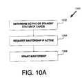
- FIG. 10Aillustrates a flow chart of an operation 1000 for a boot sequence according to one embodiment.
- the card determined to be activerequests mastership.
- the same processescan take place in the other card, i.e., both cards can run at the same time and each card can run a process to obtain mastership.
- Any number of mastership or election algorithms or techniquescan be used (e.g., a random number technique) to break a tiebreaker in the situation where both cards were active before and are ready to be active.
- the arbitration logicgrants mastership to one of the cards 910 or 950 .
- arbitration logic on active card 910grants mastership to active card 910 and arbitration logic on standby card 950 gives it a standby status.
- standby card 950needs to be updated to mirror active card 910 during the bootup sequence. That is, active card 910 boots up and SRM 918 reads configuration and state information in active card 910 , which starts running accordingly in the active state. The SRM 958 in standby card 950 will also read configuration and state information and will run in a standby state and inform SRM 918 that it is ready and in a standby state.
- FIG. 10Billustrates a flow chart of an operation 1010 for a boot sequence according to another embodiment.
- active card 910performs a bulk copy of all of its content stored in RAM data structures 912 , flash disk 924 , and non-persistent data 914 to its peer in standby card 950 using application task 916 , SRM 918 , and RCM 920 .
- routing protocol applications running on active card 910will commence copying of all pertinent information in RAM data structures 912 to is peer 952 in standby card 950 .
- only essential datahas to be copied such as state data, connection data, private routes database, etc.
- non-essential datasuch as counter information do not have to be copied.
- active card 910performs an incremental copy of any new information or data generated from new routing messages arriving from peer nodes.
- the new informationmust be copied over to standby card 950 regardless if the bulk copy operation has completed.
- a mark and sweep techniquecan be used to determine which information has been newly generated.
- concurrent incremental and bulk copyingis not allowed.
- redundancy platform 900can include any number of queues for performing incremental updating after a bulk copy operation.
- data store 922performs a redundancy copy of flash disk 924 to data store 962 and flash disk 964 in standby card 950 before any changes can be made to flash disk 924 .
- both the active card 910 and standby card 950implement a consistency verification. For instance, each router protocol needs to implement a verification that consistent information has been copied or replicated from active card 910 to standby card 950 . Once consistency is verified, the routing protocols can declare itself redundant in the standby card 950 and if the routing protocols declare themselves as redundant, router 104 is declared redundant.
- a graceful switchoverrefers to a switchover that is initiated by a user or software in a controlled manner. For example, a user can initiate a command at a command line to switch operation from active card 910 to standby card 950 for node 104 .
- SRM 918is aware of a mastership change to standby card 950 . Hence, SRM 918 prepares for the switchover in a more controlled manner and active card 910 can relinquish smoothly control of router 104 to standby card 950 .
- the SRM 918maintains a bit map of all the critical functions that are necessary for active card 910 to function in an “active state.” Tasks via application task 916 send their states to SRM 918 in the standby card 950 for a seamless and fast switchover.
- FIGS. 11A and 11Billustrate a flow chart of an operation 1100 for an active card 910 to perform a graceful switchover to a standby card 950 according to one embodiment.
- SRM 918 and RCM 920 of active card 910can be used to facilitate the fast and smooth switchover.
- active card 910verifies that a switchover is not blocked by checking if standby card 950 is inserted in router 104 or checking to see if standby card 950 is not offline.
- the standby card 950can be put in “offline” mode for upgrade purposes or for other reasons, which in effect removes the functionality of redundancy.
- the intercard communication mechanismcan be used to verify if standby card 950 is online or offline.
- SRM 918can request the state of the standby card 950 .
- the statescan be related to a card state, card type, hardware, software, and database checksums. Thus, if the returned state is “offline,” active card 910 will reject a switchover.
- active card 910verifies that standby card 950 is not offline.
- SRM 918informs the control plane or applications layer of router 104 that a switch is being performed.
- active card 910blocks all new updates to flash disk 924 .
- SRM 918 and datastore 922can block all updates to RAM data structures 912 , non-persistent data 914 , and flash disk 924 .
- SRM 918can send a message to application task 916 that all tasks are prevented from making an update such as, for example, a change in a routing table within flash disk 924 .
- the blockwill also block all new updates to standby card 950 , which is mandatory for a switchover.
- application task 916can determine whether certain data changes to RAM data structures 912 and non-persistent data 914 should not be blocked that will not be fatal for a switchover.
- SRM 918 and RCM 920replicate information in RAM data structures 912 , persistent data 914 , and flash disk 924 to its peer in standby card 950 to complete database updates.
- SRM 918verifies the configuration information on standby card 950 is identical to active card 910 .
- the SRM 958can exchange checksums in database information in standby card 950 with active card 910 . For one embodiment, if the checksums to not match, SRM 958 will replicate databases in active card 918 again and perform the verification process again. If the checksums do not match the second time, switchover will not take place.
- SRM 918informs standby card 950 to be ready to become active after replication is completed.
- Active card 910informs standby card 950 to get ready to become “active.”
- active card 910sends a message to standby card 950 to prepare to become active. Active card 910 can thus wait for an acknowledgment (i.e., “ready” or “not ready”). If standby card 950 responds with “not ready,” the switchover is aborted.
- SRM 918informs selectively application task 916 that certain tasks that are running are to go to standby. For example, SRM 918 will send a message to a select group of tasks and acknowledgment is necessary for this message. The message is to inform the tasks that the active card 910 is being brought down to a standby state.
- active card 910relinquishes its mastership of router 104 .
- SRM 918can call an I/O driver to de-assert a “master” state to relinquish mastership.
- the hardware of active card 910then gives immediate control or mastership to standby card 950 . As such, this action will forward all data coming to router 104 to standby card 950 .
- SRM 918informs application task 916 that the rest of the tasks to go to standby. That is, the functions of some tasks change as the card states change. Such a change can be propagated to all the tasks.
- SRM 918queries the tasks of their states and waits until the tasks turn to standby. This operation is mainly required for tasks which are in the active state could be performing functions that only an active card 910 should be capable of doing, e.g., responding to the management station or transmitting data on the uplink/access ports, responding to line alarms, etc. By this query/handshake, all critical tasks are guaranteed to go to standby.
- active card 910establishes communication with the active (standby card 950 ) for synchronization of databases for both persistence and non-persistence information. Once the databases are synchronized, the state of active card 910 ready for standby state.
- SRM 918removes the block made to application task 916 and data store 922 .
- active card 910is set to standby state.
- the above operationrelates to events for active card 910 .
- the events for standby card 950are described with respect to FIGS. 12A and 12B below.
- FIGS. 12A and 12Billustrate a flow chart of an operation 1200 for a standby card 950 to perform the graceful switchover according to one embodiment.
- SRM 958 and RCM 960 of standby card 950can be used to facilitate a fast and smooth switchover.
- SRM 958provides card state information and self test information to active card 910 via SRM 918 .
- RCM 960updates peer databases in standby card 950 from active card 910 .
- SRM 958provides database checksums to active card 910 via SRM 918 .
- SRM 958informs peer application task 956 that certain tasks are to become ready for active status.
- standby card 950gains mastership for router 104 the moment active card 910 relinquishes mastership.
- SRM 958informs peer application task 956 the rest of the tasks are to have an active status. SRM 958 also updates state information in standby card 950 that it has mastership.
- peer application task 956queries the tasks of their state and waits until they are in an active state. For one implementation, some tasks may restart as active if necessary.
- SRM 958blocks new network updates to RAM data structures 952 , non-persistent data 954 , and flash disk 964 on the standby card 950 .
- standby card 950changes its state to active.
- SRM 958informs the control plane or applications layer running on standby card 950 of the switchover.
- SRM 958waits until the other card (active card 910 ) is in a standby state.
- SRM 958 and/or RCM 960verifies that the data in the databases of standby card 950 are consistent with the databases of active card 910 .
- SRM 958removes the block provision to the databases in standby card 950 .
- a non-graceful switchoverrefers to a switchover that is initiated by a failure in the active card 910 without a warning.
- an active card 910can fail for any number of hardware and software reasons as will be explained in more detail below.
- the non-graceful switchoveris very similar to the graceful switchover except that there is no preparation for the switchover. That is, the switchover could happen at any moment in time for a redundant system and database updates could be pending or databases could be, e.g., in the middle of a routing table or FIB update. Moreover, some information can be lost. For one embodiment, a recovery mechanism can be implemented to recover lost information.
- FIG. 13illustrates a flow chart of an operation 1300 for a standby card 950 to perform a non-graceful switchover according to one embodiment.
- the following operation 1300is related to standby card 950 .
- active card 910performs the operation 1100 in FIG. 11 for the non-graceful switchover.
- SRM 958determines that the other card (active card 910 ) does not own mastership for router 104 .
- SRM 958informs peer application task 956 that all tasks are to go “active” and the state of the standby card 910 is to be updated as “active.”
- SRM 958queries the tasks of their states and waits until they turn “active.”
- the state of the active card 910is changed to “non-active” or “standby.”
- standby card 950informs the control plane or applications layer that standby card 950 owns mastership for router 104 and a switchover has occurred.
- Persistent informationcan include, for example, configuration information and associated files related updates, logs, stats, and etc.
- non-persistent informationwhich are stored in RAM (e.g., Ram Data Structures 912 and non-persistent data 914 ).
- Non-persistent informationincludes, for example, routing tables, session connections, etc.
- Ever task running on router 104has redundancy as part of its design. That is, every task focuses on “persistent information duplication” and “non-persistent information duplication.”
- the datastore software modules in the active card 910 and standby card 950assist in the persistent and non-persistent duplication or updating.
- FIG. 14illustrates a flow chart of an operation 1400 to update persistent information to a standby card 950 .
- the operation 1400relates to any task that invokes the datastore 922 on active card 910 to save configuration information on flash disk 924 .
- the datastore 922after updating the local flash disk 924 , sends a message across to its peer datastore 962 in standby card 950 for copying of the same information on flash disk 964 .
- the message to data store 962can be sent to peer application task 956 to update RAM data structures 952 and non-persistent data 954 with the new configuration information. For one embodiment, there can be negative or positive acknowledgments for all the transactions.
- application task 916sends a message to data store 922 to save configuration information being made in flash disk 924 .
- the messagecan contain a record identification for updating.
- datastore 924updates flash disk 924 with the configuration information. After updating the local flash disk 924 , datastore 924 sends an acknowledgement to application task 916 that flash disk 924 has been updated. Datastore 924 then sends the same message to its peer datastore 962 in standby card 950 via RCM 920 and 960 .
- datastore 962 in standby card 950updates flash disk 964 with the same update to flash disk 924 in active card 910 .
- Datastore 962sends the same set of messages to peer application task 956 that was sent to application task 916 by datastore 922 in active card 910 .
- peer application task 956interprets the messages and updates is RAM data structures 952 and non-persistent data 954 accordingly.
- FIG. 15illustrates a flow chart of an operation 1500 to update non-persistent information to standby card 950 .
- the operation 1500relates to an application task 916 that transmits a configuration change to its RAM data structures 912 and non-persistent data 914 in active card 910 and a message to its peer application task 956 in standby card 950 to update it respective RAM data structures 952 and non-persistent data 954 .
- negative or positive acknowledgmentcan be used on all the transactions.
- application task 916updates its RAM data structures 952 or non-persistent data 954 and sends a message to RCM 920 to transmit the message to standby card 950 .
- RCM 920transmits the message to peer application task 956 via RCM 960 .
- RCM 920transmits the same set of messages to peer application task 956 that application task 916 transmitted in the active card 910 .
- peer application task 956updates its RAM data structures 952 and non-persistent data 954 accordingly.
- Peer application task 956can send an acknowledgement to application task 916 in active card 910 that it has made the change.
- SRM 918 on active card 910 on receipt of acknowledgmentunblocks the blocking process that may have been implemented to prevent changes to RAM data structures 912 , non-persistent data 914 , and flash disk 924 .
- the above updating operationscan be performed for two types of updating to standby card 950 , which are referred as “bulk updates” and “delta (small) updates.”
- a bulk updaterefers to an update to the standby card 950 when standby card 950 is first inserted into router 104 and active card 910 has been operating in active mode.
- the newly inserted cardcan be a new card or a spare card or a card from another router.
- the SRMs running on active card 910 and standby card 950determine the validity and status of themselves in determining active status or standby status.
- standby card 950 that is insertedobtains a standby status. If the inserted card is functionally capable of becoming a standby, the standby card 950 must be synchronized with the active card 910 .
- a large update “bulk update”takes place between the active card 910 and the standby card 950 may have a huge routing table operating therein.
- the updateis called “bulk” because all the information in active card 910 has to be copied to standby card 950 , which can include millions of routing entries.
- SRM 918blocks all changes to the configuration of active card 910 such as, for example, command line changes or session setup changes.
- network route updatescan be queued because network topology changes must always be known even during a bulk update.
- Datastore 922 in active card 910will ensure that databases storing persistent data (i.e., information stored in flash disk 924 ) are mirrored in a memory or a flash disk 964 of the standby card 950 .
- a routing table, connection information, etc.are mirrored in active card 910 and standby card 950 .
- RCM 920informs the modules on the active card 910 of the existence of standby card 950 .
- the updatingcan be different for each application that may be used for different types of routing protocols running on active card 910 .
- Delta updatingcan be performed using the operations described above related to persistent updating and non-persistent updating. For one embodiment, even if a delta update fails and standby card 950 resumes operation, the lack of the delta update will not necessarily cause standby card 950 to fail because a peer node will resend a message. As long as the message is not committed, standby card 950 does not necessarily require the delta update to resume operation if active card 910 fails. That is, if a message or change is committed by the active card 910 , it must be made to the standby card 950 in a delta update to maintain consistency with peer nodes.
- the active card 910includes software and hardware error handling capabilities.
- SRM 918can handle software errors and error logic can handle hardware errors for active card 910 .
- FIG. 16illustrates a flow chart of an operation 1600 to perform error handling according to one embodiment.
- active card 910detects an error such as a software or hardware error. Active card 910 detects if the error requires a switchover. If the error requires a switchover, active card 910 and standby card 950 can perform a non-graceful switchover as described above.
- an errorsuch as a software or hardware error.
- Active card 910detects if the error requires a switchover. If the error requires a switchover, active card 910 and standby card 950 can perform a non-graceful switchover as described above.
- a hardware switchovertakes place to standby card 950 .
- a certain period of timeis required to perform the physical switchover, which is in the order of a few milliseconds.
- standby card 950resumes operation for router 104 .
- the standby card 950must resume operation quickly because a protocol session with router 104 may time out. Because of the delta updating of non-persistent and persistent information for relevant information changes to active card 910 , standby card 950 can resume operation seamlessly and quickly.
- a software failureis the most critical type of failure. That is, software errors are related to a number of software states and variables, which require consistency in a redundancy system. Furthermore, software errors can be difficult to detect. Common types of software failures include segmentation fault, memory corruption, memory exhaustion, application forced switchover, and infinite loops.
- a segmentation faultoccurs if there is an invalid access to memory. If there is a wrong access to memory hardware or software can detect the wrong access and generate an error to a SRM to cause a switchover. In particular, a wrong access to memory can cause incorrect information to be stored, which can create inconsistent routing table information to be stored.
- a memory exhaustion erroroccurs if too much memory space is being used. For one implementation, a warning can be given if used memory spaces reach a warning level, and a switchover can occur if the used memory space passes a certain threshold.
- An application forced switchovercan occur in software where a user forces the switchover by a command line instruction. For example, a new card being inserted that is to have active status.
- An infinite loopcan also cause a processor from processing other instructions.
- watchdog timerscan be used to determine if an instruction is an infinite loop causing a software error.
- a low priority taskcan be used to determine if the processor is stuck in an infinite processing another task. That is, if the low priority task never gets processing time, an infinite loop can be determined.
- a hardware failureis less severe than a software failure because of the redundant hardware in standby card 950 .
- Common types of hardware failuresare ASIC diagnostics failure, bus failure, memory failure, or a card failure during a power-up or boot sequence. Such hardware failures will also cause an active card to relinquish mastership and cause a switchover to standby card 950 .
- standby card 950To have routing protocol level redundancy, standby card 950 must be populated with all pertinent information required for each of the routing protocols running on the active card 910 .
- Each routing protocol module running on the active card 910 and standby card 950is responsible for maintaining a mirror copy of its protocol information in both the active card 910 and standby card 950 .
- the standby card 950can resume all routing protocol sessions of the active card 910 .
- the standby card 950resumes operation before any of the routing protocol session states times out thus preventing the failure from being observed by peer nodes.
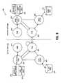
- FIG. 17illustrates a diagram 1700 to show routing protocol interaction within a node according to one embodiment.
- each routing protocol BGP 1726 , OSPF 1724 , and IS-IS 1714is associated with its own database 1731 , 1732 , and 1733 , respectively.
- Such databasescan includes specific routing protocol routes or information.
- the databases 1731 , 1732 , and 1733 for each routing protocolcan store data structures for state machines and statistics operating within routing protocols BGP 1726 , OSPF 1724 , and IS-IS 1714 .
- the forwarding table (FIB) 1702can be generated based on the routes in the IP routing table 1702 .
- FIB 1716can include forwarding information to forward packets for router 104 .
- a tertiary content addressable memory (TCAM) 1706can store the routes in FIB 1716 .
- TCAMtertiary content addressable memory
- any combination of a processor and memory systemcan be used to store and maintain FIB 1716 .
- the above routing protocol interactionis to operate in the same manner on standby card 950 if active card 910 fails.
- the information in databases 1731 , 1732 , 1733 for BGP 1726 , OSPF 1724 , and IS-IS for active card 910are replicated to the same in standby card 950 .
- the IP routing table 1702 and FIB 1716are replicated to the same in standby card 950 .
- the TCAM 1706 for the standby card 950will switch and forward packets using consistent forwarding information for router 104 .
- FIG. 18illustrates a diagram 1800 to show routing protocol interaction between an active control point and a standby control point according to another embodiment.
- a copy of the routing information within databases 1731 A, 1732 A, and 1733 A for routing protocols BGP 1726 A, OSPF 1724 A, and IS-IS 1714 A, respectively,is maintained in its peer database in the standby control point.
- active card 910will only replicate or copy static routes 1820 A to its peer static routes 1820 B in the standby control point.
- Static routersare native routes.
- the standby card 950is running in the same manner as the active card 910 except that it has no access to the ports being used for communicating to the network 100 for router 104 .
- the regular code path in the standby card 950will only redistribute and populate its IP Routing Table 1716 .
- router 104In the event of a failure to the active control point, the router 104 will switchover operation to the standby control point. Router 104 will continue routing traffic seamlessly because the standby control point has generated a valid forwarding table from the private datastore of each routing protocol. As such, a peer node communicating with router 104 can maintain routing protocol session with router 104 . Furthermore, router 104 can prevent failures from being observed by the peer node and prevent the switchovers from being observed by the peer node.
- FIG. 19illustrates an exemplary architecture 1900 for routing protocol redundancy.
- Exemplary architecture 1900includes routing protocol databases and modules for active card 910 and a standby card 950 to support routing protocol redundancy.
- Each of the modules for the active card 910 and standby card 950have two types databases for redundancy, which are redundant databases (RDBs) and persistent data bases (PDBs).
- RDBsredundant databases
- PDBspersistent data bases
- the active card 910includes Interior Gateway Protocols (IGP) module 1992 A accessing IGP RDB 1942 A and IGP RDB 1924 A.
- the IGP moduleincludes modules for OSPF, RIP, and IS-IS routing protocols.
- the active card 910also includes BGP module 1726 A accessing BGP RDB 1927 A and BGP PDB 1731 A, TCP module 1932 A accessing TCP RDB 1933 A and TCP PDB 1926 A, and an IP module 1930 A accessing an IP RDB 1931 A, and IP PDB 1928 A.
- IGPInterior Gateway Protocols
- the active card 910also includes BGP module 1726 A accessing BGP RDB 1927 A and BGP PDB 1731 A, TCP module 1932 A accessing TCP RDB 1933 A and TCP PDB 1926 A, and an IP module 1930 A accessing an IP RDB 1931 A, and IP PDB 1928 A.
- the standby card 950includes peer modules of the active card 910 accessing peer PDBs and RDBs.
- standby card 950includes IGP module 1992 B accessing IGP RDB 1942 B and IGP RDB 1924 B.
- the standby card 950also includes BGP module 1726 B accessing BGP RDB 1927 B and BGP PDB 1731 B, TCP module 1932 B accessing TCP RDB 1933 B and TCP PDB 1926 B, and an IP module 1930 B accessing an IP RDB 1931 B, and IP PDB 1928 B.
- Persistent data redundancyis handled by an internal datastore module of each active card 910 and standby card 950 . If the datastore module of active card 910 stores data to a flash disk, the same data is passed transparently to standby card 950 and in its flash disk. In addition, the peer datastore module in the standby card 950 is notified of the change and the data being changed is also passed as a part of the notification. Each of the modules is also responsible for redundancy of its only its own non-persistent data. For example, if OSPF received some updates from BGP, OSPF will not pass it to the standby card 950 . In this situation, BGP will send update to its peer BGP in standby card 950 .
- the active card 910 and standby card 950perform routing redistribution identically.
- Each of the routing protocol modules on both the active card 910 and standby card 950is responsible to send its best routes to the routing table managers (RTMs) 1940 A and 1940 B, respectively. If RTM 1940 A on the active card 910 is configured to redistribute routes to other protocols, RTM 1940 A will do so on the standby card 950 as well.
- RTM redistribution settingsare considered configuration information and is made redundant as a persistent data.
- the forwarding information tables (FIBs) 1716 A and 1716 Bare built identically on both the active card 910 and standby card 950 , respectively.
- the FIBs 1716 A and 1716 Bare based on best routes and configured administrative distance for each protocol.
- protocol distance setting information for the RTMsis considered configuration information and is made redundant as a persistent data.
- the tertiary content addressable memories (TCAMs) 1706 A and 1706 Boperate identically on the active card 910 and standby card 950 , respectively.
- the TCAMs 1706 A and 1706 Bcan be programmed based on persistent data from different modules and dynamic FIB data from the RTMs 1940 A and 1940 B.
- standby card 950(if acting in standby) has no physical line connected for the router 104 .
- standby card 950is responsible for being an interface manager to handle interface states to be in synchronization with active card 910 . That is, standby card 950 provides information to its modules and to peer modules in the active card 910 .
- BGPis the most widely used routing protocol on the Internet.
- BGPis an external gateway protocol used by routers of different autonomous systems (ASs).
- ASsautonomous systems
- a BGP routerroutes packets between network boundaries.
- a BGP routing or forwarding tablecan be very large capable of storing millions of routes.
- BGPoffers a different challenge than the other routing protocols.
- BGPuses TCP for connectivity and reliable data transfer. Consequently, if BGP loses its TCP connection with a peer, the peer reacts by immediately dropping all the routes learned from that neighboring peer. For this reason, to have BGP routing protocol redundancy, TCP must also be made redundant in order to avoid routes learned by BGP to become inaccessible.
- the redundancy platform 900 shown in FIG. 9provides the support to have BGP and TCP protocol redundancy.
- the redundancy platform 900allows a standby card 950 to relearn BGP routing and forwarding information in a short enough time as not to constitute a service outage.
- redundancy platform 900provides the support to the perform the following operations to obtain BGP and TCP protocol redundancy.
- TCP level of redundancyis an additional level of redundancy in order to have BGP routing protocol redundancy.
- the following embodimentillustrate exemplary interaction between BGP and TCP for redundant node 104 .
- FIG. 20illustrates an exemplary diagram 2000 to show the interaction between BGP, TCP, and IP.
- diagram 2000refers to active card 910 being in “active mode.”
- diagram 2000shows BGP 1726 A sending three messages to TCP 1932 A. Message 1 is 19 bytes long. Message 2 is 70 bytes long, and message 3 is 26 bytes for a total number 115 bytes.
- TCP 1932 Ais a byte stream protocol.
- TCP 1932 Aconsiders the three messages from BGP 1726 A as a stream of bytes. For example, TCP 1932 A can send the 115 bytes from BGP 1726 A as two messages to IP 1930 A. Message 1 having 85 bytes and message 2 having 30 bytes. Thus, IP 1930 A can receive the two messages from TCP 1932 A. IP 1930 A can temporarily store the two messages in a transmit buffer 2002 .
- TCP 1932 Acan store sequence numbers in the message to indicate where in the byte stream the message is located. For example, TCP 1932 A can store a next send number (NS) and a next receive number (NR) to determine order of the messages.
- the NS numberis an identifier identifying the message or packet.
- the NR numberis an identifier identifying the next message or packet in the byte stream received from remote peer.
- the window sizeis maximum number of bytes TCP 1932 A can send out before receiving an acknowledge from a peer node.
- the window size parametercan be negotiated between the peers. For example, the window size can be 8 K or 16 K.
- data passing from and through BGP 1726 A, TCP 1932 A, IP 1930 A, and transmit buffer 2002are replicated or copied into the standby card 950 until the messages have been acknowledged by the receiving peer node.
- FIG. 21Aillustrates a flow chart of an operation 2100 for replicating received or generated BGP state changes according to one embodiment.
- the following operation 2100can be implemented by redundant node 104 having an active card 910 and a standby card 950 as shown above.
- operation 2100begins at operation 2102 .
- a BGP state changeis received or generated by active card 910 .
- a peer nodecan send redundant node 104 that a BGP route is no longer available as a state change.
- the received or generated BGP state changeis replicated from the active card 910 to the standby card 950 .
- the redundancy platform 900can perform a “delta update” of the BGP state change to the standby card 950 as explained above.
- FIG. 21Billustrates a flow chart of an operation 2150 for replicating received or generated TCP state changes according to one embodiment.
- operation 2150begins at operation 2152 .
- a TCP state changeis received or generated by active card 910 .
- a peer nodecan send redundant node 104 that a TCP connection has been dropped and is no longer available as a state change.
- the received or generated TCP state changeis replicated from the active card 910 to the standby card 950 .
- the redundancy platform 900can perform a “delta update” of the TCP state change to the standby card 950 as explained above.
- the above operations 2100 and 2150allow for BGP and TCP redundancy for BGP and TCP state changes.
- the above operations 2100 and 2150can be implemented to provide selective redundancy for BGP and TCP messages. That is, some or all BGP and TCP messages can be made redundant in standby card 950 .
- a requirement for TCP level of redundancyis a BGP and TCP “lock step” requirement.
- the lock step requirementrequires that for every message that is sent or received by an active card 910 there must be an acknowledgement that the standby card 950 has stored the sent or received message before active card 910 can send or receive another message. If a switchover occurs and standby card 950 did not save the message, redundancy is broken.
- FIG. 22illustrates an exemplary dialog between an active TCP operating on active card 910 and a standby TCP operating on standby card 950 to show the lock step requirement for a BGP message being sent to a peer node.
- dialog 2200shows an active BGP 1726 A sending a BGP message (message 1 ) to active TCP 1932 A.
- Active card 910is planning to send message 1 to another router or peer node.
- Active TCP 1932 Asends message 1 to standby TCP 1932 B so that message 1 can be replicated in standby card 950 .
- Standby card 950sends an acknowledgement to active TCP 1932 A that it has replicated message 1 .
- the redundant node 104 having a redundancy platform 900will not send message 1 to the peer node via IP 1932 A until it has received an acknowledgement that message 1 has been replicated. Furthermore, redundant node 104 will not send another message (i.e., message 2 ) until it has received acknowledgment from standby TCP 1932 B that message 1 has been saved. As stated previously, if message 1 is not saved in standby card 950 , redundancy will be broken and if a switchover occurs standby card 950 cannot resume operation in the current state of active card 910 .
- active TCP 1932 AAfter active TCP 1932 A receives and acknowledgement of message 1 , it will send the “ack” to BGP 1726 A and the then BGP 1726 A can send out the second message 2 .
- active card 910will not send message to a peer node via IP 1932 A until it has received an acknowledgement that standby TCP 1932 B has stored message 2 in standby card 950 .
- By maintaining such a lock stepensures that that standby card 950 has the same BGP messages in the active card 910 that are planning to be sent out to a peer node.
- FIG. 23illustrates an exemplary dialog between an active TCP operating on active card 910 and a standby TCP operating on standby card 950 to show the lock step requirement for a BGP message being received from a peer node.
- dialog 2300shows an active TCP 1932 A in the active card 910 receiving a BGP message (message A) from remote node 102 A.
- BGP messagemessages A
- TCP 1932 Amust ensure that message A is replicated in standby card 950 . If message A is not replicated in standby card 950 , redundancy is broken.
- TCP 1932 Asends message A to it's the standby TCP 1932 B.
- the standby TCP 1932 Bsends message A to standby BGP 1726 B in standby card 950 .
- Standby TCP 1932 Bthen sends an acknowledgement to active TCP 1932 A that message A has been replicated.
- active TCP 1932 AAfter receiving the acknowledgement from standby TCP 1932 B, active TCP 1932 A sends message A to active BGP 1726 A and can then send an acknowledgement to message A to remote node 102 A.
- a second BGP message(message B) is received by active TCP 1932 A, it will also perform the same operation with message A to replicate message B in standby card 950 and wait for an acknowledgement that message B has been replicated. After receiving the acknowledgement from standby TCP 1932 B, active TCP 1932 A will send message B to active BGP 1726 A and can then send an acknowledgement to message B to remote node 102 A. Acknowledgement of message B will not occur until message A has been replicated. Thus, by maintaining such a lock step ensures that that standby card 950 has the same BGP messages that were received by active card 910 .
- FIGS. 24 and 25show varying embodiments for delta updating of individual BGP messages being sent to a peer node implementing the TCP lock step requirement as illustrated by FIG. 22 above.
- FIG. 26shows an embodiment for delta updating of individual BGP messages being received from a peer node implementing the TCP lock step requirement as illustrated in FIG. 23 above.
- FIG. 24illustrates a BGP architecture 2400 to show delta updating for individual BGP messages being sent to a peer node according to one embodiment.
- the BGP architecture 2400works on top of redundancy platform 900 as shown in FIG. 9 .
- each BGP message generated by BGP protocol running on the active card 910is updated or replicated in the standby card 950 .
- the BGP messagepasses through a number of buffering stages, which requires redundancy at every stage.
- BGP 1926 Asends a message that is stored in BGP buffer 1927 A.
- the messagemust be mirrored or replicated in standby card 950 .
- the messageis sent to redundancy manager 920 , and at reference point 3 , redundancy manager 920 sends the message to its peer redundancy manager 960 in standby card 950 via an intercard link (e.g., a “wire”).
- Redundancy manager 960now updates BGP buffer 1927 B with the message thereby having a mirror copy of the message stored in BGP buffer 1927 A.
- redundancy manager 960At reference point 5 , an acknowledgement is sent to redundancy manager 960 that the message has been updated.
- redundancy manager 960 in standby card 950sends the acknowledgement to redundancy manager 920 in active card 910 . Redundancy manager 920 thus stores the acknowledgement in BGP buffer 1927 . Afterwards, the message is passed to socket queue 2403 A.
- the above operationsare performed for reference points 9 through 28 to propagate the message through socket queue 2403 A, socket buffer 2404 A, and TCP buffer 1933 A in active card 910 .
- the message being propagated in socket queue 2403 A, socket buffer 2404 A, and TCP buffer 1933 Aare mirrored or replicated to its peer socket queue 2403 B, socket buffer 2404 B, and TCP buffer 1933 B in standby card 950 .
- the messageis passed through IP 1930 A, protocol chain manager (PCM) queue 2405 A, PCM 2006 A, driver queue 2407 A, and driver 2408 A out on a wire to the peer node.
- the socket queuesstore end-point information for the BGP protocol in which the end-point information relates to a BGP protocol running on another node.
- the PCMmanages messages designated for each type of routing protocol.
- the PCM queuesstores messages for individual routing protocols.
- FIG. 25illustrates an exemplary BGP architecture 2500 to show delta updating for individual BGP messages being for data transmit redundancy according to another embodiment.
- the exemplary BGP architecture 2500reduces the number of buffering stages between BGP and TCP/IP.
- BGPcan send messages (“packets”) directly to a buffer used by TCP/IP.
- the buffercan be a “ring buffer.”
- BGPcan control a “write” pointer to the ring buffer and TCP/IP can control a “read” pointer to the ring buffer.
- BGP 1926 Asends a message “packet” that is stored in transmit data ring 2508 A.
- the messagemust be mirrored or replicated in standby card 950 .
- the messageis sent to redundancy manager 920 , and at reference point 3 , redundancy manager 920 sends the message to its peer redundancy manager 960 in standby card 950 via an intercard link (e.g., a “wire”).
- Redundancy manager 960now updates the transmit data ring 2108 B with the message thereby having a mirror copy of the message stored in transmit data ring 2508 A.
- redundancy manager 960At reference point 5 , an acknowledgement is sent to redundancy manager 960 that the message has been updated.
- redundancy manager 960 in standby card 950sends the acknowledgement to redundancy manager 920 in active card 910 . Redundancy manager 920 thus stores the acknowledgement in transmit data ring 2508 A. Afterwards, the message is passed through TCP/IP 1930 A, PCM queue 2405 A, PCM 2406 A, driver queue 2407 A, and driver 2408 A out on a wire to the peer node.
- FIG. 26illustrates an exemplary BGP architecture 2600 for data receive according to one embodiment.
- the exemplary BGP architecture 2600is similar to BGP architecture 2500 with an addition data ring buffer (i.e., receive data ring buffer 2660 A and 2660 B).
- BGPcan receive BGP messages from the data ring buffer.
- standby card 910receives a BGP message from the a wired connection by driver 2408 A.
- driver 2408 Asends the message to PCM queue 2405 A.
- PCM queue 2405 Asends the message to PCM 2406 A.
- PCM 2406 Asends the message to TCP/IP queue 2631 A.
- TCP/IP queue 2631 Asends the message to TCP/IP 1930 A.
- TC/IP 1930 Asends the message to data receive ring buffer 2660 A.
- data receive ring buffer 2660 Asends the message to redundancy manager 920 .
- redundancy manager 920sends the message to redundancy manager 960 in the standby card 950 to be replicated.
- redundancy manager 960sends the message to data receive ring buffer 2660 B.
- an acknowledgement of the messageis stored in transmit ring data buffer 2550 B.
- the messageis sent to BGP 1726 B and the acknowledgement is sent to redundancy manager 960 .
- the acknowledgementis sent to redundancy manager 920 .
- redundancy manager 920sends the acknowledgement to data receive ring buffer 2660 A.
- the acknowledgement from redundancy manager 960is store in transmit ring buffer 2550 A.
- the messageis sent to BGP 1726 A.
- the message received by active card 910will not be sent to BGP 1726 A until it has been received by BGP 1726 B.
- the above operationsillustrate incremental updating for a received BGP message from a peer node or neighbor.
- FIG. 27illustrates a flow chart of an operation 2700 to commit to a BGP message according to one embodiment.
- the following operation 2700can be implemented by redundant node 104 having an active card 910 and a standby card 950 as shown above.
- operation 2700refers to FIG. 19 and begins at operation 2702 .
- a BGP messageis received by active card 910 .
- Active card 910sends the message up through the upper layers to an application (BGP), i.e., BGP 1726 A.
- Active card 910also sends the message to TCP 1932 B in the standby card 950 .
- the active card 910commits to the message.
- the standby card 950receives the message and sends the message from TCP 1932 B to application (BGP) on standby, i.e., BGP 1726 B.
- the standby card 950commits to the message and sends the commitment to the TCP 1932 A in active card 950 .
- the standby card 910receives the commitment from the standby card 950 and converts the commitment to a system commitment.
- the active card 910sends the system commitment to the remote peer.
- the above operation 2700uses the redundancy manager 920 and 960 to facilitate the transfer of messages between active card 910 and standby card 950 .
- the operations 2702 through 2710can be repeated for other messages, however, the system commitment for a particular will not be sent to a peer node until the standby card 950 has committed.
- the above operationsallow a BGP message to pass quickly through to the upper layers on both the active card 910 and standby card 950 .
- FIG. 28illustrates a flow chart of an operation 2800 to perform bulk updating for BGP protocol redundancy according to one embodiment.
- operation 2800refers to a boot sequence in which an active card 910 and standby card 950 are operating in a router 104 .
- BGP and TCP databasesare replicated from the active card 910 to the standby card 950 .
- the BGP RDB 1927 A and BGP PDB 1731 A in active card 910are replicated to BGP RDB 1927 B and BGP PDB 1731 B in standby card 950 .
- the bulk update operation as explained in the redundancy platform 900can be used to replicate the BGP databases.
- the TCP RDB 1933 A and TCP PDB 1926 A in active card 910are replicated to the TCP RDB 1933 B and TCP PDB 1926 B in standby card 950 using the same operation for the BGP databases.
- nonvolatile memory and other databasescan also be replicated.
- any BGP messages received or sentare queued so they can be made in the standby card 950 after the bulk update process.
- any BGP messages received or sentare delta updated to the standby card 950 using the delta update operations as shown in FIGS. 24 through 26 .
- IS-ISIntermediate System-to-Intermediate System Protocol
- the IS-IS protocolis a link state protocol.
- a router in an area/domain that generates an IS-IS protocol packetfloods all routers within the area/domain with the packet. That is, the packet generated by one IS-IS router is stored in every IS-IS router within the area or domain. Thus, each IS-IS router has a complete and consistent view of the network of other IS-IS routers. These packets are referred to as link state packets (LSP).
- LSPlink state packets
- An LSP packetincludes information about the IS router that generates the packet.
- each router running an IS-IS protocolincludes an LSP database or an IS-IS database storing LSP packets.
- the standby controller systemIn order to have IS-IS protocol redundancy, the standby controller system must maintain or be aware of configuration/global information, circuit information, adjacency information, and link state packet (LSP) information in the active controller system.
- Configuration informationincludes global information such as the global state of an active card 910 , i.e., active or standby.
- Circuit informationincludes the states of the circuits that are running. For example, are the circuits enabled/disabled.
- Adjacency informationincludes information on the adjacencies of the active, i.e., who are its neighbors.
- Link state informationincludes LSP packet information.
- the redundancy platform 900provides the support to maintain IS-IS protocol redundancy.
- FIG. 29illustrates a flow chart of an operation 2900 to perform bulk updating for IS-IS protocol redundancy according to one embodiment.
- operation 2900refers to a boot sequence in which an active card 910 and standby card 950 are operating in a router 104 .
- IS-IS databasesare replicated from the active card 910 to the standby card 950 .
- IGP RDB 1942 A and IGP PDB 1924 A and FIB 1716 A in active card 910are replicated to IGP RDB 1942 B and IGP PDB 1924 B and FIB 1716 B in standby card 950 .
- IGP databasescan be selectively copied for just IS-IS database information.
- the bulk update operation as explained in the redundancy platform 900can be used to replicate the IGP IS-IS databases.
- any IS-IS messages received or sentare queued so they can be made in the standby card 950 after the bulk update process.
- any IS-IS messages received or sentare delta updated to the standby card 950 using the delta update operations as shown in FIGS. 24 through 26 .
- FIG. 30illustrates a flow chart of an operation 3000 to perform incremental (delta) updating for individual IS-IS messages being received or sent according to one embodiment.
- operation 3000refers to router having an active card 910 and standby card 950
- an IS-IS messageis received or generated.
- IS-IS protocolcan generate a LSP or receive a LSP from a peer node.
- active card 910sends the LSP packet to standby card 950 , which is treated as neighbor.
- standby card 950replicates the LSP packet.
- the OSPF protocolis a link-state intra-domain routing protocol and relies on the IP protocol to transmit and receive packets. OSPF does not use TCP or UDP for reliable transfer of packets.
- the OSPF protocolbuilds on adjacencies with peer nodes neighbors by exchanging network information with peer nodes. OSPF updates into FIB and other protocols are made by routing table manager (RTM).
- RTMrouting table manager
- the basic requirement for OSPF protocol redundancyis to maintain undisturbed OSPF protocol services for RTM on the standby card 910 with the RTM on peer nodes. Accordingly, for OSPF protocol redundancy, all protocol state information, OSPF database information, and configuration information must be maintained in standby card 950 .
- FIG. 31illustrates a flow chart of an operation 3100 to perform bulk updating for OSPF protocol redundancy according to one embodiment.
- operation 3100refers to a boot sequence in which an active card 910 and standby card 950 are operating in a router 104 .
- OSPF databasesare replicated from the active card 910 to the standby card 950 .
- IGP RDB 1942 A and IGP PDB 1924 A and FIB 1716 A in active card 910are replicated to IGP RDB 1942 B and IGP PDB 1924 B and FIB 1716 B in standby card 950 .
- IGP databasescan be selectively copied for just OSPF database information.
- the bulk update operation as explained in the redundancy platform 900can be used to replicate the IGP OSPF databases.
- any OSPF messages received or generatedare queued so they can be made in the standby card 950 after the bulk update process.
- any OSPF messages received or sentare delta updated to the standby card 950 using the delta update operations as shown in FIGS. 24 through 26 .
- FIG. 32illustrates a flow chart of an operation 3200 to perform incremental (delta) updating for individual OSPF messages being received or sent according to one embodiment.
- operation 3200refers to router having an active card 910 and standby card 950 .
- an OSPF messageis received or generated.
- active card 910sends the received or generated OSPF message to standby card 950 using the delta update as explained in the redundancy platform 900 .
- the above described routing protocol redundancy techniques and operationsare exemplary in nature and can be applied to other types of routing protocols such as, for example, the Routing Internet Protocol (RIP).
- the redundancy platform 900can be used to perform bulk, delta, non-persistent, and persistent data updating for RIP information as described above.
- the above router and routing protocol redundancy operationscan be implemented as software routines executed by a processor.
- the soft-ware routinescan be stored on a storage device, such as a permanent memory.
- the software routinescan be machine executable instructions stored on any machine readable storage medium, such as a diskette, CD-ROM, magnetic tape, digital video or versatile disk (DVD), laser disk, ROM, Flash memory, or other like memory devices.
- the series of instructionsneed not be stored locally, and could be received from a remote storage device, such as a server on a network, a CD ROM device, a floppy disk, etc.
- the instructionsmay be copied from the storage device into a temporary memory and then accessed and executed by a processor.
- such software routinescan be written in the C programming language. It is to be appreciated, however, that these routines may be implemented in any of a wide variety of programming languages.
- the router and routing protocol redundancy operationscan be implemented in discrete hardware or firmware.
- one or more application specific integrated circuitsASICs
- the redundancy operationscan be implemented in one or more ASICs on additional circuit boards and the circuit boards could be inserted into the router or node with redundancy as described above.
- field programmable gate arraysFPGAs
- SPGAstatic programmable gate arrays
- a combination or hardware and softwarecould be used to implement redundancy operations described herein.
Landscapes
- Engineering & Computer Science (AREA)
- Computer Networks & Wireless Communication (AREA)
- Signal Processing (AREA)
- Computer Security & Cryptography (AREA)
- Data Exchanges In Wide-Area Networks (AREA)
- Hardware Redundancy (AREA)
- Communication Control (AREA)
- Mobile Radio Communication Systems (AREA)
Abstract
Description
Claims (21)
Priority Applications (12)
| Application Number | Priority Date | Filing Date | Title |
|---|---|---|---|
| US09/733,284US6910148B1 (en) | 2000-12-07 | 2000-12-07 | Router and routing protocol redundancy |
| AU2002232605AAU2002232605A1 (en) | 2000-12-07 | 2001-12-06 | Router and routing protocol redundancy |
| CA002431034ACA2431034C (en) | 2000-12-07 | 2001-12-06 | Router and routing protocol redundancy |
| JP2002548930AJP4033769B2 (en) | 2000-12-07 | 2001-12-06 | Router and routing protocol redundancy |
| ES01992133TES2267850T3 (en) | 2000-12-07 | 2001-12-06 | ENCAMINADOR AND REDUNDANCY OF ROADING PROTOCOLS. |
| PCT/US2001/048582WO2002047329A2 (en) | 2000-12-07 | 2001-12-06 | Router and routing protocol redundancy |
| CNB018220290ACN1314243C (en) | 2000-12-07 | 2001-12-06 | Route and routing protocol redundancy |
| DE60121798TDE60121798T2 (en) | 2000-12-07 | 2001-12-06 | ROUTER AND GUIDANCE PROTOCOL REDUNDANCY |
| EP01992133AEP1342340B1 (en) | 2000-12-07 | 2001-12-06 | Router and routing protocol redundancy |
| AT01992133TATE334537T1 (en) | 2000-12-07 | 2001-12-06 | ROUTER AND ROUTING PROTOCOL REDUNDANCY |
| HK04109330.6AHK1066659B (en) | 2000-12-07 | 2001-12-06 | Router and routing protocol redundancy |
| US11/124,134US7392424B2 (en) | 2000-12-07 | 2005-05-09 | Router and routing protocol redundancy |
Applications Claiming Priority (1)
| Application Number | Priority Date | Filing Date | Title |
|---|---|---|---|
| US09/733,284US6910148B1 (en) | 2000-12-07 | 2000-12-07 | Router and routing protocol redundancy |
Related Child Applications (1)
| Application Number | Title | Priority Date | Filing Date |
|---|---|---|---|
| US11/124,134ContinuationUS7392424B2 (en) | 2000-12-07 | 2005-05-09 | Router and routing protocol redundancy |
Publications (1)
| Publication Number | Publication Date |
|---|---|
| US6910148B1true US6910148B1 (en) | 2005-06-21 |
Family
ID=24946970
Family Applications (2)
| Application Number | Title | Priority Date | Filing Date |
|---|---|---|---|
| US09/733,284Expired - LifetimeUS6910148B1 (en) | 2000-12-07 | 2000-12-07 | Router and routing protocol redundancy |
| US11/124,134Expired - LifetimeUS7392424B2 (en) | 2000-12-07 | 2005-05-09 | Router and routing protocol redundancy |
Family Applications After (1)
| Application Number | Title | Priority Date | Filing Date |
|---|---|---|---|
| US11/124,134Expired - LifetimeUS7392424B2 (en) | 2000-12-07 | 2005-05-09 | Router and routing protocol redundancy |
Country Status (10)
| Country | Link |
|---|---|
| US (2) | US6910148B1 (en) |
| EP (1) | EP1342340B1 (en) |
| JP (1) | JP4033769B2 (en) |
| CN (1) | CN1314243C (en) |
| AT (1) | ATE334537T1 (en) |
| AU (1) | AU2002232605A1 (en) |
| CA (1) | CA2431034C (en) |
| DE (1) | DE60121798T2 (en) |
| ES (1) | ES2267850T3 (en) |
| WO (1) | WO2002047329A2 (en) |
Cited By (130)
| Publication number | Priority date | Publication date | Assignee | Title |
|---|---|---|---|---|
| US20020010750A1 (en)* | 2000-04-28 | 2002-01-24 | Airsys Atm Sa | Redundant input/output management device, notably for data routing |
| US20020162026A1 (en)* | 2001-02-06 | 2002-10-31 | Michael Neuman | Apparatus and method for providing secure network communication |
| US20030007500A1 (en)* | 2001-07-09 | 2003-01-09 | Alcatel | Fault-tolerant system for routing between autonomous systems |
| US20030046604A1 (en)* | 2001-05-03 | 2003-03-06 | Chun-Hung Lau | Method and system for implementing MPLS redundancy |
| US20030046418A1 (en)* | 2001-08-31 | 2003-03-06 | Jignesh Raval | Method and system for verifying the hardware implementation of TCP/IP |
| US20030140166A1 (en)* | 2002-01-24 | 2003-07-24 | Harvey Kendall William | Method and apparatus for facilitating routing protocol redundancy in a network element |
| US20030140167A1 (en)* | 2002-01-24 | 2003-07-24 | Harvey Kendall William | Method and apparatus for synchronizing redundant communication tasks |
| US20030140155A1 (en)* | 2002-01-24 | 2003-07-24 | Harvey Kendall William | Method and apparatus for providing redundant protocol processes in a network element |
| US20030185221A1 (en)* | 2002-03-29 | 2003-10-02 | Alan Deikman | Network controller with shadowing of software routing tables to hardware routing tables |
| US20030185226A1 (en)* | 2002-03-27 | 2003-10-02 | Puqi Tang | Systems and methods for updating routing and forwarding information |
| US20030227920A1 (en)* | 2002-04-11 | 2003-12-11 | Alain Benayoun | Switchover system and method in a data packet switching network |
| US20040003089A1 (en)* | 2002-06-26 | 2004-01-01 | Tienyu Chiu | Method for maintaining communication between communication devices having inconsistent protocols |
| US20040006640A1 (en)* | 2002-07-03 | 2004-01-08 | Inderieden Daniel W. | Notification to routing protocols of changes to routing information base |
| US20040008700A1 (en)* | 2002-06-27 | 2004-01-15 | Visser Lance A. | High available method for border gateway protocol version 4 |
| US20040078625A1 (en)* | 2002-01-24 | 2004-04-22 | Avici Systems, Inc. | System and method for fault tolerant data communication |
| US20040133690A1 (en)* | 2002-10-25 | 2004-07-08 | International Business Machines Corporaton | Technique for addressing a cluster of network servers |
| US20040215752A1 (en)* | 2003-03-28 | 2004-10-28 | Cisco Technology, Inc. | Network address translation with gateway load distribution |
| US20040264457A1 (en)* | 2003-06-13 | 2004-12-30 | International Business Machines Corporation | System and method for packet switch cards re-synchronization |
| US20050083953A1 (en)* | 2003-10-17 | 2005-04-21 | Ip Infusion Inc., A Delaware Corporation | System and method for providing redundant routing capabilities for a network node |
| US20050083921A1 (en)* | 2000-10-31 | 2005-04-21 | Chiaro Networks Ltd. | Router switch fabric protection using forward error correction |
| US20050094553A1 (en)* | 2003-11-03 | 2005-05-05 | Cisco Technology, Inc. | Combined electro-mechanical and solid state switching fabric |
| US20050120139A1 (en)* | 2003-10-31 | 2005-06-02 | Rajeev Kochhar | Switchover for broadband subscriber sessions |
| US20050174989A1 (en)* | 2004-02-05 | 2005-08-11 | Enke Chen | Method and an apparatus for route selection in routing protocols |
| US20050213498A1 (en)* | 2004-03-24 | 2005-09-29 | Cisco Technology, Inc. | Routing system and method for transparently recovering routing states after a failover or during a software upgrade |
| US20050223284A1 (en)* | 2004-03-25 | 2005-10-06 | Stephen Strickland | Techniques for maintaining operation of data storage system during a failure |
| US20050283643A1 (en)* | 2004-06-17 | 2005-12-22 | International Business Machines Corporation | Method and system for self-healing in routers |
| US20060062142A1 (en)* | 2004-09-22 | 2006-03-23 | Chandrashekhar Appanna | Cooperative TCP / BGP window management for stateful switchover |
| US7036051B1 (en)* | 2002-12-18 | 2006-04-25 | Juniper Networks, Inc. | Responsive virtual routing system |
| US20060092952A1 (en)* | 2004-10-13 | 2006-05-04 | Sami Boutros | System and method for reporting out-of-resources (OOR) conditions in a data network |
| US20060215547A1 (en)* | 2005-03-28 | 2006-09-28 | Koppol Pramod V N | Network transparent OSPF-TE failover |
| US20060224918A1 (en)* | 2005-03-31 | 2006-10-05 | Oki Electric Industry Co., Ltd. | Redundancy system having synchronization function and synchronization method for redundancy system |
| US20060233182A1 (en)* | 2005-04-14 | 2006-10-19 | Chandrashekhar Appanna | BGP hitless upgrade approaches |
| US20060248369A1 (en)* | 2003-04-15 | 2006-11-02 | Masayuki Kumazawa | Routing control method, router, and terminal |
| US20060268686A1 (en)* | 2005-05-26 | 2006-11-30 | Santera Systems, Inc. | Methods, systems, and computer program products for implementing automatic protection switching for media packets transmitted over an ethernet switching fabric |
| US20060274649A1 (en)* | 2005-06-06 | 2006-12-07 | Sbc Knowledge Ventures Lp | Method and apparatus for rerouting non-unicast traffic |
| US20070064698A1 (en)* | 2005-09-08 | 2007-03-22 | Chandrashekhar Appanna | Method and apparatus for transferring BGP state information during asynchronous startup |
| US20070076727A1 (en)* | 2005-09-30 | 2007-04-05 | Tekelec | Adaptive redundancy protection scheme |
| US20070086461A1 (en)* | 2005-10-17 | 2007-04-19 | Ward David D | Method for recovery of a controlled failover of a border gateway protocol speaker |
| US20070153765A1 (en)* | 2005-11-30 | 2007-07-05 | Huawei Technologies Co., Ltd. | Method for Managing Virtual Router Redundancy Protocol Backup Groups |
| US20070204320A1 (en)* | 2006-02-27 | 2007-08-30 | Fang Wu | Method and apparatus for immediate display of multicast IPTV over a bandwidth constrained network |
| US20070208927A1 (en)* | 2006-03-06 | 2007-09-06 | Alcatel | Optimized control plane signalling for a high availability network device in a communications network |
| US20070214490A1 (en)* | 2006-03-08 | 2007-09-13 | Cheng Gary F | Method for reducing channel change startup delays for multicast digital video streams |
| US20070237158A1 (en)* | 2006-03-31 | 2007-10-11 | Emc Corporation | Method and apparatus for providing a logical separation of a customer device and a service device connected to a data storage system |
| US7301894B1 (en)* | 2002-03-25 | 2007-11-27 | Westell Technologies, Inc. | Method for providing fault tolerance in an XDSL system |
| US7334048B1 (en)* | 2002-06-04 | 2008-02-19 | Extreme Networks, Inc. | Method and apparatus for fast route table update |
| US20080159325A1 (en)* | 2006-12-29 | 2008-07-03 | Futurewei Technologies, Inc. | System and method for tcp high availability |
| US7406030B1 (en)* | 2003-08-25 | 2008-07-29 | Juniper Networks, Inc. | Dynamic renegotiation of graceful restart time to avoid double-failure traffic loss |
| US20080189489A1 (en)* | 2007-02-01 | 2008-08-07 | Cisco Technology, Inc. | Regularly occurring write back scheme for cache soft error reduction |
| US20080192839A1 (en)* | 2007-02-12 | 2008-08-14 | Cisco Technology, Inc. | Fast channel change on a bandwidth constrained network |
| US20080192762A1 (en)* | 2001-06-19 | 2008-08-14 | Kireeti Kompella | Graceful restart for use in nodes employing label switched path signaling protocols |
| US20080225850A1 (en)* | 2007-03-14 | 2008-09-18 | Cisco Technology, Inc. | Unified transmission scheme for media stream redundancy |
| US20080253369A1 (en)* | 2007-04-16 | 2008-10-16 | Cisco Technology, Inc. | Monitoring and correcting upstream packet loss |
| US7502992B2 (en) | 2006-03-31 | 2009-03-10 | Emc Corporation | Method and apparatus for detecting presence of errors in data transmitted between components in a data storage system using an I2C protocol |
| US20090089774A1 (en)* | 2007-09-27 | 2009-04-02 | Lynch Timothy J | In-service software upgrade utilizing metadata-driven state translation |
| US20090092135A1 (en)* | 2001-09-17 | 2009-04-09 | Foundry Networks, Inc. | System and method for router data distribution |
| US20090154341A1 (en)* | 2007-12-12 | 2009-06-18 | Cisco Technology, Inc. | Method And Apparatus For Providing Network Redundancy |
| US7552262B1 (en) | 2005-08-31 | 2009-06-23 | Juniper Networks, Inc. | Integration of an operative standalone router into a multi-chassis router |
| US20090219931A1 (en)* | 2006-07-28 | 2009-09-03 | Boyan Tu | Method and system for synchronization of packet |
| US20090252173A1 (en)* | 2008-04-03 | 2009-10-08 | Rangaprasad Sampath | Method For Improving Efficiency Of Redundancy Protocols |
| US7606241B1 (en) | 2005-08-12 | 2009-10-20 | Juniper Networks, Inc. | Extending standalone router syntax to multi-chassis routers |
| US20100005263A1 (en)* | 2008-07-04 | 2010-01-07 | Huawei Technologies Co., Ltd. | Information backup method, firewall and network system |
| US20100091645A1 (en)* | 2008-10-15 | 2010-04-15 | Cisco Technology, Inc. | System and method for providing a multipath switchover between redundant streams |
| US7739403B1 (en)* | 2003-10-03 | 2010-06-15 | Juniper Networks, Inc. | Synchronizing state information between control units |
| US7747999B1 (en) | 2005-09-26 | 2010-06-29 | Juniper Networks, Inc. | Software installation in a multi-chassis network device |
| US20100177635A1 (en)* | 2009-01-09 | 2010-07-15 | Brocade Communications Systems, Inc. | Hierarchical rate color marker |
| US7773596B1 (en) | 2004-02-19 | 2010-08-10 | Juniper Networks, Inc. | Distribution of traffic flow criteria |
| US20100208738A1 (en)* | 2001-06-29 | 2010-08-19 | Foundry Networks, Inc. | System and method for router virtual networking |
| US7804769B1 (en)* | 2005-12-01 | 2010-09-28 | Juniper Networks, Inc. | Non-stop forwarding in a multi-chassis router |
| US7808889B1 (en)* | 2004-11-24 | 2010-10-05 | Juniper Networks, Inc. | Silent failover from a primary control unit to a backup control unit of a network device |
| US7813365B2 (en) | 2000-12-19 | 2010-10-12 | Foundry Networks, Inc. | System and method for router queue and congestion management |
| US20100274052A1 (en)* | 1997-10-02 | 2010-10-28 | University of West Ontario | Preparation of radiolabelled haloaromatics via polymer-bound intermediates |
| US20100325485A1 (en)* | 2009-06-22 | 2010-12-23 | Sandeep Kamath | Systems and methods for stateful session failover between multi-core appliances |
| US7881188B2 (en) | 2006-02-03 | 2011-02-01 | Genband Us Llc | Methods, systems, and computer program products for implementing link redundancy in a media gateway |
| US7917578B1 (en) | 2002-06-10 | 2011-03-29 | Juniper Networks, Inc. | Managing state information in a computing environment |
| US20110075646A1 (en)* | 2003-05-20 | 2011-03-31 | Belair Networks Inc. | Wireless system for communication |
| US7957330B1 (en) | 2007-11-27 | 2011-06-07 | Juniper Networks, Inc. | Failsafe management of periodic communications during system upgrade for a network device |
| US20110158101A1 (en)* | 2009-01-09 | 2011-06-30 | Brocade Communications Systems, Inc. | Hierarchical rate color marker |
| US20110161765A1 (en)* | 2006-09-11 | 2011-06-30 | Cisco Technology, Inc. | Retransmission-based stream repair and stream join |
| US7978598B1 (en)* | 2002-03-01 | 2011-07-12 | Cisco Technology, Inc. | Connection replication |
| US8001269B1 (en)* | 2002-06-18 | 2011-08-16 | Cisco Technology, Inc. | Network address translation with IP redundancy |
| US20110228772A1 (en)* | 2010-03-19 | 2011-09-22 | Brocade Communications Systems, Inc. | Providing multicast services without interruption upon a switchover |
| US20110231578A1 (en)* | 2010-03-19 | 2011-09-22 | Brocade Communications Systems, Inc. | Techniques for synchronizing application object instances |
| US20110231057A1 (en)* | 2010-03-19 | 2011-09-22 | Javad Gnss, Inc. | Method for generating offset paths for ground vehicles |
| US8031722B1 (en) | 2008-03-31 | 2011-10-04 | Emc Corporation | Techniques for controlling a network switch of a data storage system |
| US8036213B1 (en)* | 2006-03-30 | 2011-10-11 | Cisco Technology, Inc. | System and method for enhancing network stability by selectively controlling adjacency formation |
| US8078758B1 (en)* | 2003-06-05 | 2011-12-13 | Juniper Networks, Inc. | Automatic configuration of source address filters within a network device |
| US20110317559A1 (en)* | 2010-06-25 | 2011-12-29 | Kern Andras | Notifying a Controller of a Change to a Packet Forwarding Configuration of a Network Element Over a Communication Channel |
| US20120047286A1 (en)* | 2009-03-31 | 2012-02-23 | Lenovo (Beijing) Co., Ltd. | Data Processing Device for Multiple Hardware Systems, Switching Method and Computer Program Product |
| US8135857B1 (en) | 2005-09-26 | 2012-03-13 | Juniper Networks, Inc. | Centralized configuration of a multi-chassis router |
| US8149691B1 (en) | 2005-11-16 | 2012-04-03 | Juniper Networks, Inc. | Push-based hierarchical state propagation within a multi-chassis network device |
| US8190748B1 (en) | 2001-09-17 | 2012-05-29 | Foundry Networks, Inc. | System and method for router keep-alive control |
| US20120204058A1 (en)* | 2009-10-21 | 2012-08-09 | Zte Corporation | Method and Device for Backing up User Information |
| US8279879B1 (en) | 2000-10-31 | 2012-10-02 | Foundry Networks, Llc | System and method for router data aggregation and delivery |
| US8363549B1 (en) | 2009-09-02 | 2013-01-29 | Juniper Networks, Inc. | Adaptively maintaining sequence numbers on high availability peers |
| US8369345B1 (en) | 2009-11-13 | 2013-02-05 | Juniper Networks, Inc. | Multi-router system having shared network interfaces |
| US8472311B2 (en) | 2010-02-04 | 2013-06-25 | Genband Us Llc | Systems, methods, and computer readable media for providing instantaneous failover of packet processing elements in a network |
| US8495418B2 (en) | 2010-07-23 | 2013-07-23 | Brocade Communications Systems, Inc. | Achieving ultra-high availability using a single CPU |
| US20140050225A1 (en)* | 2002-04-16 | 2014-02-20 | Brocade Communications Systems, Inc. | System and method for providing network route redundancy across layer 2 devices |
| US8700952B2 (en) | 2006-12-29 | 2014-04-15 | Futurewei Technologies, Inc. | System and method for completeness of TCP data in TCP HA |
| US20140105001A1 (en)* | 2010-03-26 | 2014-04-17 | Rockstar Consortium Us Lp | Distributed Failure Recovery in a Routed Ethernet Network |
| US20140199942A1 (en)* | 2013-01-17 | 2014-07-17 | Strata Products Worldwide, Llc | Method, Controller, and System for Tunnel Communication |
| US8787153B2 (en) | 2008-02-10 | 2014-07-22 | Cisco Technology, Inc. | Forward error correction based data recovery with path diversity |
| US8797886B1 (en) | 2006-01-30 | 2014-08-05 | Juniper Networks, Inc. | Verification of network paths using two or more connectivity protocols |
| US8902780B1 (en) | 2012-09-26 | 2014-12-02 | Juniper Networks, Inc. | Forwarding detection for point-to-multipoint label switched paths |
| US8949458B1 (en) | 2003-02-07 | 2015-02-03 | Juniper Networks, Inc. | Automatic filtering to prevent network attacks |
| US8953460B1 (en) | 2012-12-31 | 2015-02-10 | Juniper Networks, Inc. | Network liveliness detection using session-external communications |
| US9032095B1 (en)* | 2004-01-06 | 2015-05-12 | Juniper Networks, Inc. | Routing device having multiple logical routers |
| US20150134606A1 (en)* | 2013-11-14 | 2015-05-14 | Vmware, Inc. | Intelligent data propagation in a highly distributed environment |
| US20150134607A1 (en)* | 2013-11-14 | 2015-05-14 | Vmware, Inc. | Intelligent data propagation using performance monitoring |
| US9104619B2 (en) | 2010-07-23 | 2015-08-11 | Brocade Communications Systems, Inc. | Persisting data across warm boots |
| US9143335B2 (en) | 2011-09-16 | 2015-09-22 | Brocade Communications Systems, Inc. | Multicast route cache system |
| US9203690B2 (en) | 2012-09-24 | 2015-12-01 | Brocade Communications Systems, Inc. | Role based multicast messaging infrastructure |
| US9258234B1 (en) | 2012-12-28 | 2016-02-09 | Juniper Networks, Inc. | Dynamically adjusting liveliness detection intervals for periodic network communications |
| US9274851B2 (en) | 2009-11-25 | 2016-03-01 | Brocade Communications Systems, Inc. | Core-trunking across cores on physically separated processors allocated to a virtual machine based on configuration information including context information for virtual machines |
| US9619349B2 (en) | 2014-10-14 | 2017-04-11 | Brocade Communications Systems, Inc. | Biasing active-standby determination |
| US9769017B1 (en) | 2014-09-26 | 2017-09-19 | Juniper Networks, Inc. | Impending control plane disruption indication using forwarding plane liveliness detection protocols |
| US9967106B2 (en) | 2012-09-24 | 2018-05-08 | Brocade Communications Systems LLC | Role based multicast messaging infrastructure |
| US10031782B2 (en) | 2012-06-26 | 2018-07-24 | Juniper Networks, Inc. | Distributed processing of network device tasks |
| US10193801B2 (en) | 2013-11-25 | 2019-01-29 | Juniper Networks, Inc. | Automatic traffic mapping for multi-protocol label switching networks |
| US10333788B2 (en) | 2015-12-29 | 2019-06-25 | Alibaba Group Holding Limited | System and method for acquiring, processing and updating global information |
| US10374936B2 (en) | 2015-12-30 | 2019-08-06 | Juniper Networks, Inc. | Reducing false alarms when using network keep-alive messages |
| US20190245771A1 (en)* | 2016-10-17 | 2019-08-08 | New H3C Technologies Co., Ltd. | Transmitting bgp message |
| US10397085B1 (en) | 2016-06-30 | 2019-08-27 | Juniper Networks, Inc. | Offloading heartbeat responses message processing to a kernel of a network device |
| US10425502B2 (en) | 2015-12-29 | 2019-09-24 | Alibaba Group Holding Limited | System and method for acquiring, processing and updating global information |
| US10440069B2 (en) | 2015-12-29 | 2019-10-08 | Alibaba Group Holding Limited | System and method for acquiring, processing, and updating global information |
| US10447571B2 (en)* | 2018-01-12 | 2019-10-15 | Cisco Technology, Inc. | Dataplane-based seamless bidirectional forwarding detection monitoring for network entities |
| US10581763B2 (en) | 2012-09-21 | 2020-03-03 | Avago Technologies International Sales Pte. Limited | High availability application messaging layer |
| US10771316B1 (en)* | 2017-11-30 | 2020-09-08 | Amazon Technologies, Inc. | Debugging of a network device through emulation |
| CN116489085A (en)* | 2023-03-28 | 2023-07-25 | 网根科技(青岛)有限公司 | Analytical route security monitoring method and system based on Handle |
| US11750441B1 (en) | 2018-09-07 | 2023-09-05 | Juniper Networks, Inc. | Propagating node failure errors to TCP sockets |
Families Citing this family (74)
| Publication number | Priority date | Publication date | Assignee | Title |
|---|---|---|---|---|
| FR2819360B1 (en) | 2001-01-11 | 2003-04-11 | Cit Alcatel | ROUTING SYSTEM PROVIDING THE CONTINUITY OF SERVICE OF THE INTERFACES ASSOCIATED WITH NEIGHBORING NETWORKS |
| FR2819359B1 (en) | 2001-01-11 | 2003-04-11 | Cit Alcatel | ROUTING SYSTEM PROVIDING CONTINUITY OF SERVICE, STATE MACHINES ASSOCIATED WITH NEIGHBORING ROUTING SYSTEMS |
| JP3908483B2 (en)* | 2001-06-28 | 2007-04-25 | 富士通株式会社 | Communication device |
| US7406527B2 (en)* | 2001-11-02 | 2008-07-29 | Microsoft Corporation | Method for advance negotiation of computer settings |
| US7440394B2 (en) | 2002-06-24 | 2008-10-21 | Nokia Corporation | Method and system for redundant IP forwarding in a telecommunications network |
| FI20021235A0 (en)* | 2002-06-24 | 2002-06-24 | Nokia Corp | A method and system for redundant IP forwarding in a telecommunications network |
| US20060256767A1 (en)* | 2003-06-11 | 2006-11-16 | Nec Corporation | Router and network connecting method |
| EP1501257A1 (en)* | 2003-07-25 | 2005-01-26 | Hewlett-Packard Development Company, L.P. | Improvements in or relating to fault tolerant systems |
| US7562145B2 (en)* | 2003-08-28 | 2009-07-14 | International Business Machines Corporation | Application instance level workload distribution affinities |
| US7178052B2 (en)* | 2003-09-18 | 2007-02-13 | Cisco Technology, Inc. | High availability virtual switch |
| US7839843B2 (en) | 2003-09-18 | 2010-11-23 | Cisco Technology, Inc. | Distributed forwarding in virtual network devices |
| US7751416B2 (en)* | 2003-09-18 | 2010-07-06 | Cisco Technology, Inc. | Virtual network device |
| WO2005039142A1 (en)* | 2003-10-17 | 2005-04-28 | Siemens Aktiengesellschaft | A basic message service for redundant devices |
| US8526427B1 (en) | 2003-10-21 | 2013-09-03 | Cisco Technology, Inc. | Port-based loadsharing for a satellite switch |
| US20050111352A1 (en)* | 2003-11-21 | 2005-05-26 | Boon Ho | Method and system for monitoring a network containing routers using a backup routing protocol |
| CN100407727C (en)* | 2004-01-18 | 2008-07-30 | 中兴通讯股份有限公司 | A Message-Based Interprocessor Communication Method |
| US8990430B2 (en) | 2004-02-19 | 2015-03-24 | Cisco Technology, Inc. | Interface bundles in virtual network devices |
| US8208370B1 (en) | 2004-03-31 | 2012-06-26 | Cisco Technology, Inc. | Method and system for fast link failover |
| US7889733B2 (en) | 2004-04-28 | 2011-02-15 | Cisco Technology, Inc. | Intelligent adjunct network device |
| FR2870420B1 (en)* | 2004-05-17 | 2006-09-08 | Alcatel Sa | DEVICE FOR MANAGING A MOBILITY PROTOCOL FOR AN EQUIPMENT OF AN IP COMMUNICATIONS NETWORK, FOR SERVICE CONTINUITY |
| US7706364B2 (en)* | 2004-05-19 | 2010-04-27 | Cisco Technology, Inc. | Virtual network device clusters |
| US7710957B2 (en)* | 2004-05-19 | 2010-05-04 | Cisco Technology, Inc. | System and method for implementing multiple spanning trees per network |
| US7436836B2 (en) | 2004-06-30 | 2008-10-14 | Cisco Technology, Inc. | Method and apparatus for detecting support for a protocol defining supplemental headers |
| US7808983B2 (en) | 2004-07-08 | 2010-10-05 | Cisco Technology, Inc. | Network device architecture for centralized packet processing |
| US8730976B2 (en) | 2004-08-17 | 2014-05-20 | Cisco Technology, Inc. | System and method for preventing erroneous link aggregation due to component relocation |
| US8693350B2 (en)* | 2004-10-26 | 2014-04-08 | Jds Uniphase Corporation | Method of collecting BGP routing protocol messages |
| US7742444B2 (en) | 2005-03-15 | 2010-06-22 | Qualcomm Incorporated | Multiple other sector information combining for power control in a wireless communication system |
| JP2006311254A (en)* | 2005-04-28 | 2006-11-09 | Kddi Corp | Network system |
| US7751311B2 (en)* | 2005-05-19 | 2010-07-06 | Cisco Technology, Inc. | High availability transport protocol method and apparatus |
| US8750908B2 (en) | 2005-06-16 | 2014-06-10 | Qualcomm Incorporated | Quick paging channel with reduced probability of missed page |
| US9055552B2 (en) | 2005-06-16 | 2015-06-09 | Qualcomm Incorporated | Quick paging channel with reduced probability of missed page |
| KR20070024302A (en)* | 2005-08-26 | 2007-03-02 | 한국전자통신연구원 | Sleep mode control device and control method of cellular system |
| CA2557678A1 (en)* | 2005-09-08 | 2007-03-08 | Jing Wu | Recovery from control plane interruptions in communication networks |
| JP4747758B2 (en)* | 2005-09-21 | 2011-08-17 | 日立電線株式会社 | Network equipment |
| US20100150106A1 (en) | 2005-10-27 | 2010-06-17 | Qualcomm Incorporated | Method and apparatus for managing assignment during handoff in wireless communication systems |
| US20090207790A1 (en) | 2005-10-27 | 2009-08-20 | Qualcomm Incorporated | Method and apparatus for settingtuneawaystatus in an open state in wireless communication system |
| US7957380B2 (en)* | 2005-11-21 | 2011-06-07 | Cisco Technology, Inc. | Support of unidirectional link in IS-IS without IP encapsulation and in presence of unidirectional return path |
| US7509528B2 (en)* | 2006-03-10 | 2009-03-24 | Alcatel Lucent | Transaction bundling for improved redundancy |
| US8284656B2 (en)* | 2006-04-28 | 2012-10-09 | Alcatel Lucent | System and method for resilient VPLS over multi-nodal APS protected provider edge nodes |
| US8208372B2 (en)* | 2006-06-02 | 2012-06-26 | Cisco Technology, Inc. | Technique for fast activation of a secondary head-end node TE-LSP upon failure of a primary head-end node TE-LSP |
| US8441924B2 (en)* | 2006-07-20 | 2013-05-14 | Verizon Services Organization Inc. | Redundant capability in a fiber optic network |
| CN101193092A (en)* | 2006-11-29 | 2008-06-04 | 鸿富锦精密工业(深圳)有限公司 | Network device and its data synchronous transmission method |
| CN100579072C (en)* | 2006-12-22 | 2010-01-06 | 华为技术有限公司 | A method and system for communicating between IP devices |
| US20080285437A1 (en)* | 2007-05-18 | 2008-11-20 | Adc Dsl Systems, Inc. | Ethernet protection switching system |
| US8442072B2 (en)* | 2007-05-25 | 2013-05-14 | Futurewei Technologies, Inc. | Method of preventing transport leaks in hybrid switching networks by extension of the link layer discovery protocol (LLDP) |
| US8243591B2 (en)* | 2008-02-12 | 2012-08-14 | Alcatel Lucent | Method and tool for router interface L2 redundancy |
| JP5113684B2 (en)* | 2008-09-05 | 2013-01-09 | 株式会社日立製作所 | Access gateway device control method and communication system |
| US8644186B1 (en) | 2008-10-03 | 2014-02-04 | Cisco Technology, Inc. | System and method for detecting loops for routing in a network environment |
| CN101534309B (en) | 2009-04-14 | 2013-03-13 | 华为技术有限公司 | A node registration method, a routing update method, a communication system and the relevant equipment |
| US8045477B2 (en)* | 2009-07-17 | 2011-10-25 | Cisco Technology, Inc. | Smart protection escalation mechanism prevention |
| US8154992B2 (en)* | 2009-08-11 | 2012-04-10 | Google Inc. | System and method for graceful restart |
| US8873377B2 (en)* | 2009-11-18 | 2014-10-28 | Juniper Networks, Inc. | Method and apparatus for hitless failover in networking systems using single database |
| US8842673B2 (en)* | 2010-11-22 | 2014-09-23 | Nec Corporation | Communication system, communication device, controller, and method and program for controlling forwarding path of packet flow |
| CN102761577B (en)* | 2011-04-29 | 2015-05-20 | 深圳友讯达科技股份有限公司 | CFDA (cellular fixed-wireless digital access) acquisition platform |
| US20120281695A1 (en)* | 2011-05-05 | 2012-11-08 | Brocade Communications Systems, Inc. | Control packet bicasting between stackable devices |
| US8614941B2 (en)* | 2011-05-09 | 2013-12-24 | Telefonaktiebolaget L M Ericsson (Publ) | Hitless switchover from active TCP application to standby TCP application |
| US8913485B2 (en)* | 2011-09-16 | 2014-12-16 | Telefonaktiebolaget L M Ericsson (Publ) | Open shortest path first (OSPF) nonstop routing (NSR) with link derivation |
| US8923312B2 (en) | 2011-09-29 | 2014-12-30 | Telefonaktiebolaget L M Ericsson (Publ) | OSPF nonstop routing synchronization nack |
| US8964758B2 (en) | 2011-09-29 | 2015-02-24 | Telefonaktiebolaget L M Ericsson (Publ) | OSPF nonstop routing (NSR) synchronization reduction |
| JP5703201B2 (en)* | 2011-12-02 | 2015-04-15 | アラクサラネットワークス株式会社 | Redundant control device and network system |
| US20140149819A1 (en)* | 2012-11-28 | 2014-05-29 | Telefonaktiebolaget L M Ericsson (Publ) | Method and apparatus for protocol data unit recovery in an is-is system |
| CN103973571A (en)* | 2013-02-05 | 2014-08-06 | 中兴通讯股份有限公司 | Network processor and routing searching method |
| US9256660B2 (en) | 2013-08-06 | 2016-02-09 | Telefonaktiebolaget L M Ericsson (Publ) | Reconciliation protocol after ICR switchover during bulk sync |
| CN104821913B (en)* | 2015-05-05 | 2019-01-29 | 新华三技术有限公司 | A kind of data message forwarding method and device |
| US9778354B2 (en) | 2015-08-10 | 2017-10-03 | Mitsubishi Electric Research Laboratories, Inc. | Method and system for coding signals using distributed coding and non-monotonic quantization |
| US9501717B1 (en) | 2015-08-10 | 2016-11-22 | Mitsubishi Electric Research Laboratories, Inc. | Method and system for coding signals using distributed coding and non-monotonic quantization |
| WO2017053960A1 (en) | 2015-09-25 | 2017-03-30 | Fsa Technologies, Inc. | Flow control system and method |
| CN110249591B (en)* | 2016-12-16 | 2022-05-10 | 赫思曼自动化控制有限公司 | Method for optimizing fault detection using redundancy protocol of test data packet |
| DE112019003589T5 (en)* | 2018-08-24 | 2021-07-15 | Hitachi Automotive Systems, Ltd. | IN-VEHICLE COMMUNICATION DEVICE AND IN-VEHICLE SYSTEM |
| US10901399B2 (en)* | 2018-09-28 | 2021-01-26 | Rockwell Automation Technologies, Inc. | High availability industrial automation controller and method of operating the same |
| CN115208824B (en)* | 2019-03-13 | 2025-07-25 | 华为技术有限公司 | Route information management method, device and computer storage medium |
| CN113728598A (en) | 2019-05-23 | 2021-11-30 | 慧与发展有限责任合伙企业 | System and method for a reduction engine to facilitate self-management |
| CN113765781B (en)* | 2020-06-04 | 2022-07-12 | 华为技术有限公司 | Method, communication device, storage medium and system for processing routing message |
| CN114374642B (en)* | 2021-12-29 | 2023-06-16 | 中国电信股份有限公司 | Maintenance method and device for route information |
Citations (8)
| Publication number | Priority date | Publication date | Assignee | Title |
|---|---|---|---|---|
| US5473599A (en) | 1994-04-22 | 1995-12-05 | Cisco Systems, Incorporated | Standby router protocol |
| WO1996012363A1 (en) | 1994-10-12 | 1996-04-25 | 3Com Corporation | Remote smart filtering communication management system |
| US5870382A (en)* | 1995-09-04 | 1999-02-09 | Fujitsu Limited | Automatic protection switching system for ATM exchange network |
| US5936936A (en) | 1997-04-11 | 1999-08-10 | International Business Machines Corporation | Redundancy mechanisms for classical internet protocol over asynchronous transfer mode networks |
| US6148410A (en)* | 1997-09-15 | 2000-11-14 | International Business Machines Corporation | Fault tolerant recoverable TCP/IP connection router |
| US20020176355A1 (en)* | 2001-05-22 | 2002-11-28 | Alan Mimms | Snooping standby router |
| US6490246B2 (en)* | 1997-11-20 | 2002-12-03 | Hitachi, Ltd. | System and method for using active and standby routers wherein both routers have the same ID even before a failure occurs |
| US6577634B1 (en)* | 1998-07-01 | 2003-06-10 | Hitachi, Ltd. | Method for sharing network information and a router apparatus |
Family Cites Families (7)
| Publication number | Priority date | Publication date | Assignee | Title |
|---|---|---|---|---|
| US5471469A (en) | 1994-02-08 | 1995-11-28 | Metricon, Inc. | Method of resolving media contention in radio communication links |
| US5453977A (en) | 1994-02-08 | 1995-09-26 | Metricom, Inc. | Method for network configuration via third party query |
| US5513314A (en)* | 1995-01-27 | 1996-04-30 | Auspex Systems, Inc. | Fault tolerant NFS server system and mirroring protocol |
| US6366558B1 (en)* | 1997-05-02 | 2002-04-02 | Cisco Technology, Inc. | Method and apparatus for maintaining connection state between a connection manager and a failover device |
| JP3204302B2 (en) | 1997-11-27 | 2001-09-04 | 日本電気株式会社 | Network element management system and database updating method therefor |
| US6415323B1 (en)* | 1999-09-03 | 2002-07-02 | Fastforward Networks | Proximity-based redirection system for robust and scalable service-node location in an internetwork |
| US6885635B1 (en)* | 2000-11-21 | 2005-04-26 | Juniper Networks, Inc. | High capacity router having redundant components |
- 2000
- 2000-12-07USUS09/733,284patent/US6910148B1/ennot_activeExpired - Lifetime
- 2001
- 2001-12-06CACA002431034Apatent/CA2431034C/ennot_activeExpired - Fee Related
- 2001-12-06CNCNB018220290Apatent/CN1314243C/ennot_activeExpired - Lifetime
- 2001-12-06ESES01992133Tpatent/ES2267850T3/ennot_activeExpired - Lifetime
- 2001-12-06EPEP01992133Apatent/EP1342340B1/ennot_activeExpired - Lifetime
- 2001-12-06JPJP2002548930Apatent/JP4033769B2/ennot_activeExpired - Fee Related
- 2001-12-06DEDE60121798Tpatent/DE60121798T2/ennot_activeExpired - Lifetime
- 2001-12-06ATAT01992133Tpatent/ATE334537T1/ennot_activeIP Right Cessation
- 2001-12-06AUAU2002232605Apatent/AU2002232605A1/ennot_activeAbandoned
- 2001-12-06WOPCT/US2001/048582patent/WO2002047329A2/enactiveIP Right Grant
- 2005
- 2005-05-09USUS11/124,134patent/US7392424B2/ennot_activeExpired - Lifetime
Patent Citations (8)
| Publication number | Priority date | Publication date | Assignee | Title |
|---|---|---|---|---|
| US5473599A (en) | 1994-04-22 | 1995-12-05 | Cisco Systems, Incorporated | Standby router protocol |
| WO1996012363A1 (en) | 1994-10-12 | 1996-04-25 | 3Com Corporation | Remote smart filtering communication management system |
| US5870382A (en)* | 1995-09-04 | 1999-02-09 | Fujitsu Limited | Automatic protection switching system for ATM exchange network |
| US5936936A (en) | 1997-04-11 | 1999-08-10 | International Business Machines Corporation | Redundancy mechanisms for classical internet protocol over asynchronous transfer mode networks |
| US6148410A (en)* | 1997-09-15 | 2000-11-14 | International Business Machines Corporation | Fault tolerant recoverable TCP/IP connection router |
| US6490246B2 (en)* | 1997-11-20 | 2002-12-03 | Hitachi, Ltd. | System and method for using active and standby routers wherein both routers have the same ID even before a failure occurs |
| US6577634B1 (en)* | 1998-07-01 | 2003-06-10 | Hitachi, Ltd. | Method for sharing network information and a router apparatus |
| US20020176355A1 (en)* | 2001-05-22 | 2002-11-28 | Alan Mimms | Snooping standby router |
Non-Patent Citations (14)
| Title |
|---|
| "BGP"; Dec. 4, 2002; Whatis.com Target Search; pp. 1-2; http://whatis.techtarget.com/definition/0,,sid9 _gci213813,00.html.* |
| "Layer 3"; Jul. 29, 2001; searchNetworking.com Definitions; p. 1; http://searchnetworking.techtarget.com/sDefinition/0,,sid7_gci214604,00.html.* |
| "The Technology of IP Routers in the New Public Network", Ericsson IP Infrastructure, Jan. 2000, p. 1-21. |
| "Unleash the Power, Building Multi-Service IP Networks with ATM Cores", The ATM Forum, p. 1-12, printed in Belgium-Mar. 1999. |
| Afek et al, "Trainet: a new label switching sheme", INFOCOM 2000, Nineteenth Annual Joint Conference of the IEEE Computer and Communications Societies. Proceedings. IEEE, Mar. 26, 2000, pp. 874-883, XP010376177. |
| Garcia-Luna-Aceves et al, "Scalable link-state Internet Routing", Network Protocols, 1998. Proceedings. Sixth International Conference on Austin, Texas, Oct. 13-16, 1998, IEEE COMPUT.Soc., pp. 52-61, XP010309349. |
| George Swallow, "MPLA Advantages for Traffic Engineering", IEEE Communications Magazine, Dec. 1999, p. 54-57. |
| J.Y. Liu, T.T. Chiam, and K.K. Kwong, "Temasek Polytechnic Campus Network Design & Implementation: A Case Study," XP010365608, Internet Workshop, 1999, Osaka, Japan, pp. 209-214 (Feb, 18-20, 1999). |
| Liu et al, "Temasek Polytechnic campus network design and implementation: a case study" Internet Workshop, 1999. IWS 99 Osaka, Japan, Feb. 18-20, 1999, pp. 209-214, XP010365608. |
| Livevault Corporation: "Real Time Replicator Concepts Guide",Real Time Replicator Concepts Guide, Jun. 2000, pp. 1-4, XP002295399, Retrieved from Internet: URL:http://www.livevault.com/support/knowledge/rtrcg_2_4.pdf>. |
| Massey et al, "Fault detection in routing protocols", IEEE, Oct. 31, 1999, pp. 31-40, XP010356973. |
| PCT Invitation to Pay Additional Fees for PCT Counterpart Appl. No. PCT/US01/48582 Containing International Search Report (Jun. 17, 2002). |
| Wilder Floyd, "A Guide to TCP/IP Protocol Suite second edition", 1998, Artech House, Norwood, MA, USA, XP002295400, p. 182-184. |
| Zhou et al.; "Fast Cluster Failover Using Virtual Memory-Mapped Communication"; 1999; ACM; ICS '99 Rhodes Greece; pp. 373-382.* |
Cited By (242)
| Publication number | Priority date | Publication date | Assignee | Title |
|---|---|---|---|---|
| US20100274052A1 (en)* | 1997-10-02 | 2010-10-28 | University of West Ontario | Preparation of radiolabelled haloaromatics via polymer-bound intermediates |
| US7707281B2 (en)* | 2000-04-28 | 2010-04-27 | Airsys Atm S.A. | Redundant input/output management device, notably for data routing |
| US20020010750A1 (en)* | 2000-04-28 | 2002-01-24 | Airsys Atm Sa | Redundant input/output management device, notably for data routing |
| US8315175B2 (en) | 2000-10-31 | 2012-11-20 | Foundry Networks, Llc | Router switch fabric protection using forward error correction |
| US8279879B1 (en) | 2000-10-31 | 2012-10-02 | Foundry Networks, Llc | System and method for router data aggregation and delivery |
| US20050083921A1 (en)* | 2000-10-31 | 2005-04-21 | Chiaro Networks Ltd. | Router switch fabric protection using forward error correction |
| US7974208B2 (en) | 2000-12-19 | 2011-07-05 | Foundry Networks, Inc. | System and method for router queue and congestion management |
| US7813365B2 (en) | 2000-12-19 | 2010-10-12 | Foundry Networks, Inc. | System and method for router queue and congestion management |
| US20020162026A1 (en)* | 2001-02-06 | 2002-10-31 | Michael Neuman | Apparatus and method for providing secure network communication |
| US20030046604A1 (en)* | 2001-05-03 | 2003-03-06 | Chun-Hung Lau | Method and system for implementing MPLS redundancy |
| US7093160B2 (en)* | 2001-05-03 | 2006-08-15 | Nokia Corporation | Method and system for implementing MPLS redundancy |
| US20080192762A1 (en)* | 2001-06-19 | 2008-08-14 | Kireeti Kompella | Graceful restart for use in nodes employing label switched path signaling protocols |
| US7903651B2 (en)* | 2001-06-19 | 2011-03-08 | Juniper Networks, Inc. | Graceful restart for use in nodes employing label switched path signaling protocols |
| US20100208738A1 (en)* | 2001-06-29 | 2010-08-19 | Foundry Networks, Inc. | System and method for router virtual networking |
| US8010637B2 (en) | 2001-06-29 | 2011-08-30 | Foundry Networks, Inc. | System and method for router virtual networking |
| US20030007500A1 (en)* | 2001-07-09 | 2003-01-09 | Alcatel | Fault-tolerant system for routing between autonomous systems |
| US20030046418A1 (en)* | 2001-08-31 | 2003-03-06 | Jignesh Raval | Method and system for verifying the hardware implementation of TCP/IP |
| US7020716B2 (en)* | 2001-08-31 | 2006-03-28 | Adaptec, Inc. | Method and system for verifying the hardware implementation of TCP/IP |
| US8190748B1 (en) | 2001-09-17 | 2012-05-29 | Foundry Networks, Inc. | System and method for router keep-alive control |
| US8977753B1 (en) | 2001-09-17 | 2015-03-10 | Brocade Communication Systems, Inc. | System and method for router keep-alive control |
| US8335219B2 (en) | 2001-09-17 | 2012-12-18 | Foundry Networks, Llc | System and method for router data distribution |
| US20090092135A1 (en)* | 2001-09-17 | 2009-04-09 | Foundry Networks, Inc. | System and method for router data distribution |
| US20040078625A1 (en)* | 2002-01-24 | 2004-04-22 | Avici Systems, Inc. | System and method for fault tolerant data communication |
| US7406035B2 (en) | 2002-01-24 | 2008-07-29 | Alcatel-Lucent Canada Inc. | Method and apparatus for providing redundant protocol processes in a network element |
| US8005980B2 (en)* | 2002-01-24 | 2011-08-23 | Alcatel Lucent | Method and apparatus for synchronizing redundant communication tasks |
| US20030140155A1 (en)* | 2002-01-24 | 2003-07-24 | Harvey Kendall William | Method and apparatus for providing redundant protocol processes in a network element |
| US20030140167A1 (en)* | 2002-01-24 | 2003-07-24 | Harvey Kendall William | Method and apparatus for synchronizing redundant communication tasks |
| US20030140166A1 (en)* | 2002-01-24 | 2003-07-24 | Harvey Kendall William | Method and apparatus for facilitating routing protocol redundancy in a network element |
| US8769154B2 (en)* | 2002-01-24 | 2014-07-01 | Alcatel Lucent | Method and apparatus for facilitating routing protocol redundancy in a network element |
| US7978598B1 (en)* | 2002-03-01 | 2011-07-12 | Cisco Technology, Inc. | Connection replication |
| US7301894B1 (en)* | 2002-03-25 | 2007-11-27 | Westell Technologies, Inc. | Method for providing fault tolerance in an XDSL system |
| US20030185226A1 (en)* | 2002-03-27 | 2003-10-02 | Puqi Tang | Systems and methods for updating routing and forwarding information |
| US7209449B2 (en)* | 2002-03-27 | 2007-04-24 | Intel Corporation | Systems and methods for updating routing and forwarding information |
| US20030185221A1 (en)* | 2002-03-29 | 2003-10-02 | Alan Deikman | Network controller with shadowing of software routing tables to hardware routing tables |
| US7304941B2 (en)* | 2002-04-11 | 2007-12-04 | International Business Machines Corporation | Switchover system and method in a data packet switching network |
| US20030227920A1 (en)* | 2002-04-11 | 2003-12-11 | Alain Benayoun | Switchover system and method in a data packet switching network |
| US9450893B2 (en)* | 2002-04-16 | 2016-09-20 | Brocade Communications Systems, Inc. | System and method for providing network route redundancy across layer 2 devices |
| US20140050225A1 (en)* | 2002-04-16 | 2014-02-20 | Brocade Communications Systems, Inc. | System and method for providing network route redundancy across layer 2 devices |
| US7334048B1 (en)* | 2002-06-04 | 2008-02-19 | Extreme Networks, Inc. | Method and apparatus for fast route table update |
| US7917578B1 (en) | 2002-06-10 | 2011-03-29 | Juniper Networks, Inc. | Managing state information in a computing environment |
| US8082364B1 (en) | 2002-06-10 | 2011-12-20 | Juniper Networks, Inc. | Managing state information in a computing environment |
| US8001269B1 (en)* | 2002-06-18 | 2011-08-16 | Cisco Technology, Inc. | Network address translation with IP redundancy |
| US8037196B2 (en)* | 2002-06-26 | 2011-10-11 | Alcatel Lucent | Method for maintaining communication between communication devices having inconsistent protocols |
| US20040003089A1 (en)* | 2002-06-26 | 2004-01-01 | Tienyu Chiu | Method for maintaining communication between communication devices having inconsistent protocols |
| US8467287B2 (en)* | 2002-06-27 | 2013-06-18 | Foundry Networks, Llc | High available method for border gateway protocol version 4 |
| US7499394B2 (en)* | 2002-06-27 | 2009-03-03 | Foundry Networks, Inc. | System for highly available border gateway protocol |
| US20070248108A1 (en)* | 2002-06-27 | 2007-10-25 | Visser Lance A | System for highly available border gateway protocol |
| US7236453B2 (en)* | 2002-06-27 | 2007-06-26 | Jeremy Benjamin, Trustee | High available method for border gateway protocol version 4 |
| US20090129261A1 (en)* | 2002-06-27 | 2009-05-21 | Foundry Networks, Inc. | High available method for border gateway protocol version 4 |
| US20040008700A1 (en)* | 2002-06-27 | 2004-01-15 | Visser Lance A. | High available method for border gateway protocol version 4 |
| US20040006640A1 (en)* | 2002-07-03 | 2004-01-08 | Inderieden Daniel W. | Notification to routing protocols of changes to routing information base |
| US20040133690A1 (en)* | 2002-10-25 | 2004-07-08 | International Business Machines Corporaton | Technique for addressing a cluster of network servers |
| US7991914B2 (en) | 2002-10-25 | 2011-08-02 | International Business Machines Corporation | Technique for addressing a cluster of network servers |
| US7480737B2 (en)* | 2002-10-25 | 2009-01-20 | International Business Machines Corporation | Technique for addressing a cluster of network servers |
| US7318179B1 (en)* | 2002-12-18 | 2008-01-08 | Juniper Networks, Inc. | Virtual routing system for real-time network applications |
| US7036051B1 (en)* | 2002-12-18 | 2006-04-25 | Juniper Networks, Inc. | Responsive virtual routing system |
| US8949458B1 (en) | 2003-02-07 | 2015-02-03 | Juniper Networks, Inc. | Automatic filtering to prevent network attacks |
| US20040215752A1 (en)* | 2003-03-28 | 2004-10-28 | Cisco Technology, Inc. | Network address translation with gateway load distribution |
| US7764696B2 (en)* | 2003-04-15 | 2010-07-27 | Panasonic Corporation | Routing control method, router, and terminal |
| US20060248369A1 (en)* | 2003-04-15 | 2006-11-02 | Masayuki Kumazawa | Routing control method, router, and terminal |
| US8340064B2 (en) | 2003-05-20 | 2012-12-25 | Belair Network Inc. | Wireless system for communication |
| US20110075646A1 (en)* | 2003-05-20 | 2011-03-31 | Belair Networks Inc. | Wireless system for communication |
| US8687532B1 (en) | 2003-05-20 | 2014-04-01 | Belair Networks Inc. | Wireless method, system and device for communicaton |
| US8687531B2 (en) | 2003-05-20 | 2014-04-01 | Belair Networks Inc. | Wireless system for communication |
| US8078758B1 (en)* | 2003-06-05 | 2011-12-13 | Juniper Networks, Inc. | Automatic configuration of source address filters within a network device |
| US7751312B2 (en)* | 2003-06-13 | 2010-07-06 | International Business Machines Corporation | System and method for packet switch cards re-synchronization |
| US20040264457A1 (en)* | 2003-06-13 | 2004-12-30 | International Business Machines Corporation | System and method for packet switch cards re-synchronization |
| US7948870B1 (en) | 2003-08-25 | 2011-05-24 | Juniper Networks, Inc. | Dynamic renegotiation of graceful restart time to avoid double-failure traffic loss |
| US7406030B1 (en)* | 2003-08-25 | 2008-07-29 | Juniper Networks, Inc. | Dynamic renegotiation of graceful restart time to avoid double-failure traffic loss |
| US7739403B1 (en)* | 2003-10-03 | 2010-06-15 | Juniper Networks, Inc. | Synchronizing state information between control units |
| US8799511B1 (en)* | 2003-10-03 | 2014-08-05 | Juniper Networks, Inc. | Synchronizing state information between control units |
| US8009556B2 (en)* | 2003-10-17 | 2011-08-30 | Ip Infusion, Inc. | System and method for providing redundant routing capabilities for a network node |
| US20050135233A1 (en)* | 2003-10-17 | 2005-06-23 | Ip Infusion Inc., A Delaware Corporation | Redundant routing capabilities for a network node cluster |
| US20050083953A1 (en)* | 2003-10-17 | 2005-04-21 | Ip Infusion Inc., A Delaware Corporation | System and method for providing redundant routing capabilities for a network node |
| US7894335B2 (en)* | 2003-10-17 | 2011-02-22 | Ip Infusion, Inc. | Redundant routing capabilities for a network node cluster |
| US20050120139A1 (en)* | 2003-10-31 | 2005-06-02 | Rajeev Kochhar | Switchover for broadband subscriber sessions |
| US7929424B2 (en) | 2003-10-31 | 2011-04-19 | Ericsson Ab | Switchover for broadband subscriber sessions |
| WO2005043936A3 (en)* | 2003-10-31 | 2007-01-18 | Redback Networks Inc | Switchover for broadband subscriber sessions |
| US7599285B2 (en)* | 2003-11-03 | 2009-10-06 | Cisco Technology, Inc. | Combined electro-mechanical and solid state switching fabric |
| US20050094553A1 (en)* | 2003-11-03 | 2005-05-05 | Cisco Technology, Inc. | Combined electro-mechanical and solid state switching fabric |
| US9832099B1 (en) | 2004-01-06 | 2017-11-28 | Juniper Networks, Inc. | Routing device having multiple logical routers |
| US9485149B1 (en)* | 2004-01-06 | 2016-11-01 | Juniper Networks, Inc. | Routing device having multiple logical routers |
| US9032095B1 (en)* | 2004-01-06 | 2015-05-12 | Juniper Networks, Inc. | Routing device having multiple logical routers |
| US20050174989A1 (en)* | 2004-02-05 | 2005-08-11 | Enke Chen | Method and an apparatus for route selection in routing protocols |
| US8265058B2 (en)* | 2004-02-05 | 2012-09-11 | Ericsson Ab | Method and an apparatus for route selection in routing protocols |
| US7773596B1 (en) | 2004-02-19 | 2010-08-10 | Juniper Networks, Inc. | Distribution of traffic flow criteria |
| US7506194B2 (en)* | 2004-03-24 | 2009-03-17 | Cisco Technology, Inc. | Routing system and method for transparently rocovering routing states after a failover or during a software upgrade |
| WO2005104439A3 (en)* | 2004-03-24 | 2007-05-31 | Cisco Tech Inc | Routing system and method for transparently recovering routing states after a failover or during a software upgrade |
| US20050213498A1 (en)* | 2004-03-24 | 2005-09-29 | Cisco Technology, Inc. | Routing system and method for transparently recovering routing states after a failover or during a software upgrade |
| US7293198B2 (en)* | 2004-03-25 | 2007-11-06 | Emc Corporation | Techniques for maintaining operation of data storage system during a failure |
| US20050223284A1 (en)* | 2004-03-25 | 2005-10-06 | Stephen Strickland | Techniques for maintaining operation of data storage system during a failure |
| US7284148B2 (en)* | 2004-06-17 | 2007-10-16 | International Business Machines Corporation | Method and system for self-healing in routers |
| US20050283643A1 (en)* | 2004-06-17 | 2005-12-22 | International Business Machines Corporation | Method and system for self-healing in routers |
| US7515525B2 (en)* | 2004-09-22 | 2009-04-07 | Cisco Technology, Inc. | Cooperative TCP / BGP window management for stateful switchover |
| US20060062142A1 (en)* | 2004-09-22 | 2006-03-23 | Chandrashekhar Appanna | Cooperative TCP / BGP window management for stateful switchover |
| US9699087B2 (en) | 2004-10-13 | 2017-07-04 | Cisco Technology, Inc. | System and method for reporting out-of-resources (OOR) conditions in a data network |
| US20060092952A1 (en)* | 2004-10-13 | 2006-05-04 | Sami Boutros | System and method for reporting out-of-resources (OOR) conditions in a data network |
| US8717899B2 (en)* | 2004-10-13 | 2014-05-06 | Cisco Technology, Inc. | System and method for reporting out-of-resources (OOR) conditions in a data network |
| US7808889B1 (en)* | 2004-11-24 | 2010-10-05 | Juniper Networks, Inc. | Silent failover from a primary control unit to a backup control unit of a network device |
| US8503288B1 (en)* | 2004-11-24 | 2013-08-06 | Juniper Networks, Inc. | Silent failover from a primary control unit to a backup control unit of a network device |
| US20060215547A1 (en)* | 2005-03-28 | 2006-09-28 | Koppol Pramod V N | Network transparent OSPF-TE failover |
| US7573811B2 (en)* | 2005-03-28 | 2009-08-11 | Alcatel-Lucent Usa Inc. | Network transparent OSPF-TE failover |
| US7770062B2 (en) | 2005-03-31 | 2010-08-03 | Oki Electric Industry Co., Ltd. | Redundancy system having synchronization function and synchronization method for redundancy system |
| US20060224918A1 (en)* | 2005-03-31 | 2006-10-05 | Oki Electric Industry Co., Ltd. | Redundancy system having synchronization function and synchronization method for redundancy system |
| US20090089613A1 (en)* | 2005-03-31 | 2009-04-02 | Oki Electric Industry Co., Ltd. | Redundancy system having syncronization function and syncronization method for redundancy system |
| US7475284B2 (en)* | 2005-03-31 | 2009-01-06 | Oki Electric Industry Co., Ltd. | Redundancy system having synchronization function and synchronization method for redundancy system |
| US20060233182A1 (en)* | 2005-04-14 | 2006-10-19 | Chandrashekhar Appanna | BGP hitless upgrade approaches |
| US7609617B2 (en)* | 2005-04-14 | 2009-10-27 | Cisco Technology, Inc. | BGP hitless upgrade approaches |
| US20060268686A1 (en)* | 2005-05-26 | 2006-11-30 | Santera Systems, Inc. | Methods, systems, and computer program products for implementing automatic protection switching for media packets transmitted over an ethernet switching fabric |
| US8040899B2 (en) | 2005-05-26 | 2011-10-18 | Genband Us Llc | Methods, systems, and computer program products for implementing automatic protection switching for media packets transmitted over an ethernet switching fabric |
| US20060274649A1 (en)* | 2005-06-06 | 2006-12-07 | Sbc Knowledge Ventures Lp | Method and apparatus for rerouting non-unicast traffic |
| US7606241B1 (en) | 2005-08-12 | 2009-10-20 | Juniper Networks, Inc. | Extending standalone router syntax to multi-chassis routers |
| US8040902B1 (en) | 2005-08-12 | 2011-10-18 | Juniper Networks, Inc. | Extending standalone router syntax to multi-chassis routers |
| US7552262B1 (en) | 2005-08-31 | 2009-06-23 | Juniper Networks, Inc. | Integration of an operative standalone router into a multi-chassis router |
| US7899930B1 (en) | 2005-08-31 | 2011-03-01 | Juniper Networks, Inc. | Integration of an operative standalone router into a multi-chassis router |
| US20070064698A1 (en)* | 2005-09-08 | 2007-03-22 | Chandrashekhar Appanna | Method and apparatus for transferring BGP state information during asynchronous startup |
| US9166904B2 (en) | 2005-09-08 | 2015-10-20 | Cisco Technology, Inc. | Method and apparatus for transferring BGP state information during asynchronous startup |
| US8370831B1 (en) | 2005-09-26 | 2013-02-05 | Juniper Networks, Inc. | Software installation in a multi-chassis network device |
| US8904380B1 (en) | 2005-09-26 | 2014-12-02 | Juniper Networks, Inc. | Software installation on a multi-chassis network device |
| US8135857B1 (en) | 2005-09-26 | 2012-03-13 | Juniper Networks, Inc. | Centralized configuration of a multi-chassis router |
| US7747999B1 (en) | 2005-09-26 | 2010-06-29 | Juniper Networks, Inc. | Software installation in a multi-chassis network device |
| US20070076727A1 (en)* | 2005-09-30 | 2007-04-05 | Tekelec | Adaptive redundancy protection scheme |
| US7911940B2 (en) | 2005-09-30 | 2011-03-22 | Genband Us Llc | Adaptive redundancy protection scheme |
| US20070086461A1 (en)* | 2005-10-17 | 2007-04-19 | Ward David D | Method for recovery of a controlled failover of a border gateway protocol speaker |
| US7948873B2 (en)* | 2005-10-17 | 2011-05-24 | Cisco Technology, Inc. | Method for recovery of a controlled failover of a border gateway protocol speaker |
| US8149691B1 (en) | 2005-11-16 | 2012-04-03 | Juniper Networks, Inc. | Push-based hierarchical state propagation within a multi-chassis network device |
| US7835270B2 (en)* | 2005-11-30 | 2010-11-16 | Huawei Technologies Co., Ltd. | Method for managing virtual router redundancy protocol backup groups |
| US20070153765A1 (en)* | 2005-11-30 | 2007-07-05 | Huawei Technologies Co., Ltd. | Method for Managing Virtual Router Redundancy Protocol Backup Groups |
| CN1980230B (en)* | 2005-11-30 | 2011-06-01 | 华为技术有限公司 | Methods for Managing VRRP Groups |
| US7804769B1 (en)* | 2005-12-01 | 2010-09-28 | Juniper Networks, Inc. | Non-stop forwarding in a multi-chassis router |
| US20110013508A1 (en)* | 2005-12-01 | 2011-01-20 | Juniper Networks, Inc. | Non-stop forwarding in a multi-chassis router |
| US8483048B2 (en) | 2005-12-01 | 2013-07-09 | Juniper Networks, Inc. | Non-stop forwarding in a multi-chassis router |
| US8797886B1 (en) | 2006-01-30 | 2014-08-05 | Juniper Networks, Inc. | Verification of network paths using two or more connectivity protocols |
| US7881188B2 (en) | 2006-02-03 | 2011-02-01 | Genband Us Llc | Methods, systems, and computer program products for implementing link redundancy in a media gateway |
| US20070204320A1 (en)* | 2006-02-27 | 2007-08-30 | Fang Wu | Method and apparatus for immediate display of multicast IPTV over a bandwidth constrained network |
| US7965771B2 (en) | 2006-02-27 | 2011-06-21 | Cisco Technology, Inc. | Method and apparatus for immediate display of multicast IPTV over a bandwidth constrained network |
| US8462847B2 (en) | 2006-02-27 | 2013-06-11 | Cisco Technology, Inc. | Method and apparatus for immediate display of multicast IPTV over a bandwidth constrained network |
| US7512776B2 (en)* | 2006-03-06 | 2009-03-31 | Alcatel Lucent | Optimized control plane signalling for a high availability network device in a communications network |
| US20070208927A1 (en)* | 2006-03-06 | 2007-09-06 | Alcatel | Optimized control plane signalling for a high availability network device in a communications network |
| US8218654B2 (en) | 2006-03-08 | 2012-07-10 | Cisco Technology, Inc. | Method for reducing channel change startup delays for multicast digital video streams |
| US20070214490A1 (en)* | 2006-03-08 | 2007-09-13 | Cheng Gary F | Method for reducing channel change startup delays for multicast digital video streams |
| US8953470B2 (en) | 2006-03-30 | 2015-02-10 | Cisco Technology, Inc. | System and method for enhancing network stability by selectively controlling adjacency formation |
| US8036213B1 (en)* | 2006-03-30 | 2011-10-11 | Cisco Technology, Inc. | System and method for enhancing network stability by selectively controlling adjacency formation |
| US7502992B2 (en) | 2006-03-31 | 2009-03-10 | Emc Corporation | Method and apparatus for detecting presence of errors in data transmitted between components in a data storage system using an I2C protocol |
| US8089903B2 (en) | 2006-03-31 | 2012-01-03 | Emc Corporation | Method and apparatus for providing a logical separation of a customer device and a service device connected to a data storage system |
| US20070237158A1 (en)* | 2006-03-31 | 2007-10-11 | Emc Corporation | Method and apparatus for providing a logical separation of a customer device and a service device connected to a data storage system |
| US20090219931A1 (en)* | 2006-07-28 | 2009-09-03 | Boyan Tu | Method and system for synchronization of packet |
| US7957269B2 (en)* | 2006-07-28 | 2011-06-07 | Huawei Technologies Co., Ltd. | Method and system for synchronization of packet |
| US8031701B2 (en) | 2006-09-11 | 2011-10-04 | Cisco Technology, Inc. | Retransmission-based stream repair and stream join |
| US9083585B2 (en) | 2006-09-11 | 2015-07-14 | Cisco Technology, Inc. | Retransmission-based stream repair and stream join |
| US20110161765A1 (en)* | 2006-09-11 | 2011-06-30 | Cisco Technology, Inc. | Retransmission-based stream repair and stream join |
| US8588077B2 (en) | 2006-09-11 | 2013-11-19 | Cisco Technology, Inc. | Retransmission-based stream repair and stream join |
| US20080159325A1 (en)* | 2006-12-29 | 2008-07-03 | Futurewei Technologies, Inc. | System and method for tcp high availability |
| US8700952B2 (en) | 2006-12-29 | 2014-04-15 | Futurewei Technologies, Inc. | System and method for completeness of TCP data in TCP HA |
| US9648147B2 (en)* | 2006-12-29 | 2017-05-09 | Futurewei Technologies, Inc. | System and method for TCP high availability |
| US20080189489A1 (en)* | 2007-02-01 | 2008-08-07 | Cisco Technology, Inc. | Regularly occurring write back scheme for cache soft error reduction |
| US7937531B2 (en) | 2007-02-01 | 2011-05-03 | Cisco Technology, Inc. | Regularly occurring write back scheme for cache soft error reduction |
| US20080192839A1 (en)* | 2007-02-12 | 2008-08-14 | Cisco Technology, Inc. | Fast channel change on a bandwidth constrained network |
| US8769591B2 (en) | 2007-02-12 | 2014-07-01 | Cisco Technology, Inc. | Fast channel change on a bandwidth constrained network |
| US7940644B2 (en)* | 2007-03-14 | 2011-05-10 | Cisco Technology, Inc. | Unified transmission scheme for media stream redundancy |
| US20080225850A1 (en)* | 2007-03-14 | 2008-09-18 | Cisco Technology, Inc. | Unified transmission scheme for media stream redundancy |
| US20080253369A1 (en)* | 2007-04-16 | 2008-10-16 | Cisco Technology, Inc. | Monitoring and correcting upstream packet loss |
| US8711854B2 (en) | 2007-04-16 | 2014-04-29 | Cisco Technology, Inc. | Monitoring and correcting upstream packet loss |
| US8806472B2 (en)* | 2007-09-27 | 2014-08-12 | Ericsson Ab | In-service software upgrade utilizing metadata-driven state translation |
| US20090089774A1 (en)* | 2007-09-27 | 2009-04-02 | Lynch Timothy J | In-service software upgrade utilizing metadata-driven state translation |
| US7957330B1 (en) | 2007-11-27 | 2011-06-07 | Juniper Networks, Inc. | Failsafe management of periodic communications during system upgrade for a network device |
| US20090154341A1 (en)* | 2007-12-12 | 2009-06-18 | Cisco Technology, Inc. | Method And Apparatus For Providing Network Redundancy |
| US8134915B2 (en)* | 2007-12-12 | 2012-03-13 | Cisco Technology, Inc. | Method and apparatus for providing network redundancy |
| US8787153B2 (en) | 2008-02-10 | 2014-07-22 | Cisco Technology, Inc. | Forward error correction based data recovery with path diversity |
| US8031722B1 (en) | 2008-03-31 | 2011-10-04 | Emc Corporation | Techniques for controlling a network switch of a data storage system |
| US20090252173A1 (en)* | 2008-04-03 | 2009-10-08 | Rangaprasad Sampath | Method For Improving Efficiency Of Redundancy Protocols |
| US20100005263A1 (en)* | 2008-07-04 | 2010-01-07 | Huawei Technologies Co., Ltd. | Information backup method, firewall and network system |
| US7969974B2 (en) | 2008-10-15 | 2011-06-28 | Cisco Technology, Inc. | System and method for providing a multipath switchover between redundant streams |
| US20100091645A1 (en)* | 2008-10-15 | 2010-04-15 | Cisco Technology, Inc. | System and method for providing a multipath switchover between redundant streams |
| US9350674B2 (en) | 2009-01-09 | 2016-05-24 | Brocade Communications Systems, Inc. | Hierarchical rate color marker |
| US8730812B2 (en) | 2009-01-09 | 2014-05-20 | Brocade Communications Systems, Inc. | Hierarchical rate color marker |
| US8467296B2 (en) | 2009-01-09 | 2013-06-18 | Foundry Networks, Llc | Hierarchical rate color marker |
| US20110158101A1 (en)* | 2009-01-09 | 2011-06-30 | Brocade Communications Systems, Inc. | Hierarchical rate color marker |
| US20100177635A1 (en)* | 2009-01-09 | 2010-07-15 | Brocade Communications Systems, Inc. | Hierarchical rate color marker |
| US20120047286A1 (en)* | 2009-03-31 | 2012-02-23 | Lenovo (Beijing) Co., Ltd. | Data Processing Device for Multiple Hardware Systems, Switching Method and Computer Program Product |
| US8868795B2 (en)* | 2009-03-31 | 2014-10-21 | Lenovo (Beijing) Co., Ltd. | Data processing device for multiple hardware systems, switching method and computer program product |
| US20100325485A1 (en)* | 2009-06-22 | 2010-12-23 | Sandeep Kamath | Systems and methods for stateful session failover between multi-core appliances |
| US8335943B2 (en)* | 2009-06-22 | 2012-12-18 | Citrix Systems, Inc. | Systems and methods for stateful session failover between multi-core appliances |
| US8363549B1 (en) | 2009-09-02 | 2013-01-29 | Juniper Networks, Inc. | Adaptively maintaining sequence numbers on high availability peers |
| US20120204058A1 (en)* | 2009-10-21 | 2012-08-09 | Zte Corporation | Method and Device for Backing up User Information |
| US8935564B2 (en)* | 2009-10-21 | 2015-01-13 | Zte Corporation | Method for backing up user information and apparatus in standby service node for backing up user information |
| US9444768B1 (en) | 2009-11-13 | 2016-09-13 | Juniper Networks, Inc. | Multi-router system having shared network interfaces |
| US8369345B1 (en) | 2009-11-13 | 2013-02-05 | Juniper Networks, Inc. | Multi-router system having shared network interfaces |
| US9274851B2 (en) | 2009-11-25 | 2016-03-01 | Brocade Communications Systems, Inc. | Core-trunking across cores on physically separated processors allocated to a virtual machine based on configuration information including context information for virtual machines |
| US8472311B2 (en) | 2010-02-04 | 2013-06-25 | Genband Us Llc | Systems, methods, and computer readable media for providing instantaneous failover of packet processing elements in a network |
| US9094221B2 (en) | 2010-03-19 | 2015-07-28 | Brocade Communications Systems, Inc. | Synchronizing multicast information for linecards |
| US20110228772A1 (en)* | 2010-03-19 | 2011-09-22 | Brocade Communications Systems, Inc. | Providing multicast services without interruption upon a switchover |
| US8406125B2 (en) | 2010-03-19 | 2013-03-26 | Brocade Communications Systems, Inc. | Synchronization of multicast information using incremental updates |
| US9276756B2 (en) | 2010-03-19 | 2016-03-01 | Brocade Communications Systems, Inc. | Synchronization of multicast information using incremental updates |
| US20110231578A1 (en)* | 2010-03-19 | 2011-09-22 | Brocade Communications Systems, Inc. | Techniques for synchronizing application object instances |
| US20110231057A1 (en)* | 2010-03-19 | 2011-09-22 | Javad Gnss, Inc. | Method for generating offset paths for ground vehicles |
| US8576703B2 (en) | 2010-03-19 | 2013-11-05 | Brocade Communications Systems, Inc. | Synchronization of multicast information using bicasting |
| US8769155B2 (en)* | 2010-03-19 | 2014-07-01 | Brocade Communications Systems, Inc. | Techniques for synchronizing application object instances |
| US8503289B2 (en) | 2010-03-19 | 2013-08-06 | Brocade Communications Systems, Inc. | Synchronizing multicast information for linecards |
| US20140105001A1 (en)* | 2010-03-26 | 2014-04-17 | Rockstar Consortium Us Lp | Distributed Failure Recovery in a Routed Ethernet Network |
| US9001647B2 (en)* | 2010-03-26 | 2015-04-07 | Rpx Clearinghouse Llc | Distributed failure recovery in a routed ethernet network |
| US20110317559A1 (en)* | 2010-06-25 | 2011-12-29 | Kern Andras | Notifying a Controller of a Change to a Packet Forwarding Configuration of a Network Element Over a Communication Channel |
| US8897134B2 (en)* | 2010-06-25 | 2014-11-25 | Telefonaktiebolaget L M Ericsson (Publ) | Notifying a controller of a change to a packet forwarding configuration of a network element over a communication channel |
| US9104619B2 (en) | 2010-07-23 | 2015-08-11 | Brocade Communications Systems, Inc. | Persisting data across warm boots |
| US8495418B2 (en) | 2010-07-23 | 2013-07-23 | Brocade Communications Systems, Inc. | Achieving ultra-high availability using a single CPU |
| US9026848B2 (en) | 2010-07-23 | 2015-05-05 | Brocade Communications Systems, Inc. | Achieving ultra-high availability using a single CPU |
| US9143335B2 (en) | 2011-09-16 | 2015-09-22 | Brocade Communications Systems, Inc. | Multicast route cache system |
| US11614972B2 (en) | 2012-06-26 | 2023-03-28 | Juniper Networks, Inc. | Distributed processing of network device tasks |
| US10031782B2 (en) | 2012-06-26 | 2018-07-24 | Juniper Networks, Inc. | Distributed processing of network device tasks |
| US10581763B2 (en) | 2012-09-21 | 2020-03-03 | Avago Technologies International Sales Pte. Limited | High availability application messaging layer |
| US11757803B2 (en) | 2012-09-21 | 2023-09-12 | Avago Technologies International Sales Pte. Limited | High availability application messaging layer |
| US9203690B2 (en) | 2012-09-24 | 2015-12-01 | Brocade Communications Systems, Inc. | Role based multicast messaging infrastructure |
| US9967106B2 (en) | 2012-09-24 | 2018-05-08 | Brocade Communications Systems LLC | Role based multicast messaging infrastructure |
| US8902780B1 (en) | 2012-09-26 | 2014-12-02 | Juniper Networks, Inc. | Forwarding detection for point-to-multipoint label switched paths |
| US9258234B1 (en) | 2012-12-28 | 2016-02-09 | Juniper Networks, Inc. | Dynamically adjusting liveliness detection intervals for periodic network communications |
| US9781058B1 (en) | 2012-12-28 | 2017-10-03 | Juniper Networks, Inc. | Dynamically adjusting liveliness detection intervals for periodic network communications |
| US9407526B1 (en) | 2012-12-31 | 2016-08-02 | Juniper Networks, Inc. | Network liveliness detection using session-external communications |
| US8953460B1 (en) | 2012-12-31 | 2015-02-10 | Juniper Networks, Inc. | Network liveliness detection using session-external communications |
| US9118409B2 (en)* | 2013-01-17 | 2015-08-25 | Strata Products Worldwide, Llc | Method, controller, and system for tunnel communication |
| US20140199942A1 (en)* | 2013-01-17 | 2014-07-17 | Strata Products Worldwide, Llc | Method, Controller, and System for Tunnel Communication |
| US9621654B2 (en) | 2013-11-14 | 2017-04-11 | Vmware, Inc. | Intelligent data propagation using performance monitoring |
| US9230001B2 (en)* | 2013-11-14 | 2016-01-05 | Vmware, Inc. | Intelligent data propagation using performance monitoring |
| US9268836B2 (en)* | 2013-11-14 | 2016-02-23 | Vmware, Inc. | Intelligent data propagation in a highly distributed environment |
| US20150134606A1 (en)* | 2013-11-14 | 2015-05-14 | Vmware, Inc. | Intelligent data propagation in a highly distributed environment |
| US20150134607A1 (en)* | 2013-11-14 | 2015-05-14 | Vmware, Inc. | Intelligent data propagation using performance monitoring |
| US10193801B2 (en) | 2013-11-25 | 2019-01-29 | Juniper Networks, Inc. | Automatic traffic mapping for multi-protocol label switching networks |
| US9769017B1 (en) | 2014-09-26 | 2017-09-19 | Juniper Networks, Inc. | Impending control plane disruption indication using forwarding plane liveliness detection protocols |
| US9619349B2 (en) | 2014-10-14 | 2017-04-11 | Brocade Communications Systems, Inc. | Biasing active-standby determination |
| US10333788B2 (en) | 2015-12-29 | 2019-06-25 | Alibaba Group Holding Limited | System and method for acquiring, processing and updating global information |
| US10425502B2 (en) | 2015-12-29 | 2019-09-24 | Alibaba Group Holding Limited | System and method for acquiring, processing and updating global information |
| US10440069B2 (en) | 2015-12-29 | 2019-10-08 | Alibaba Group Holding Limited | System and method for acquiring, processing, and updating global information |
| US10374936B2 (en) | 2015-12-30 | 2019-08-06 | Juniper Networks, Inc. | Reducing false alarms when using network keep-alive messages |
| US10951506B1 (en) | 2016-06-30 | 2021-03-16 | Juniper Networks, Inc. | Offloading heartbeat responses message processing to a kernel of a network device |
| US10397085B1 (en) | 2016-06-30 | 2019-08-27 | Juniper Networks, Inc. | Offloading heartbeat responses message processing to a kernel of a network device |
| US10862792B2 (en)* | 2016-10-17 | 2020-12-08 | New H3C Technologies Co., Ltd. | Transmitting BGP message |
| US20190245771A1 (en)* | 2016-10-17 | 2019-08-08 | New H3C Technologies Co., Ltd. | Transmitting bgp message |
| US10771316B1 (en)* | 2017-11-30 | 2020-09-08 | Amazon Technologies, Inc. | Debugging of a network device through emulation |
| US10785137B2 (en) | 2018-01-12 | 2020-09-22 | Cisco Technology, Inc. | Dataplane-based seamless bidirectional forwarding detection monitoring for network entities |
| US10447571B2 (en)* | 2018-01-12 | 2019-10-15 | Cisco Technology, Inc. | Dataplane-based seamless bidirectional forwarding detection monitoring for network entities |
| US11750441B1 (en) | 2018-09-07 | 2023-09-05 | Juniper Networks, Inc. | Propagating node failure errors to TCP sockets |
| CN116489085A (en)* | 2023-03-28 | 2023-07-25 | 网根科技(青岛)有限公司 | Analytical route security monitoring method and system based on Handle |
| CN116489085B (en)* | 2023-03-28 | 2023-10-27 | 网根科技(青岛)有限公司 | Analytical route security monitoring method and system based on Handle |
Also Published As
| Publication number | Publication date |
|---|---|
| JP2004534414A (en) | 2004-11-11 |
| CN1314243C (en) | 2007-05-02 |
| CN1502191A (en) | 2004-06-02 |
| ATE334537T1 (en) | 2006-08-15 |
| WO2002047329A2 (en) | 2002-06-13 |
| EP1342340B1 (en) | 2006-07-26 |
| US7392424B2 (en) | 2008-06-24 |
| EP1342340A2 (en) | 2003-09-10 |
| WO2002047329A3 (en) | 2003-06-05 |
| DE60121798D1 (en) | 2006-09-07 |
| ES2267850T3 (en) | 2007-03-16 |
| DE60121798T2 (en) | 2007-08-09 |
| US20050265346A1 (en) | 2005-12-01 |
| CA2431034C (en) | 2009-06-02 |
| CA2431034A1 (en) | 2002-06-13 |
| AU2002232605A1 (en) | 2002-06-18 |
| JP4033769B2 (en) | 2008-01-16 |
| HK1066659A1 (en) | 2005-03-24 |
Similar Documents
| Publication | Publication Date | Title |
|---|---|---|
| US6910148B1 (en) | Router and routing protocol redundancy | |
| KR101099822B1 (en) | Active routing component failure handling method and apparatus | |
| US7518986B1 (en) | Push-based hierarchical state propagation within a multi-chassis network device | |
| US8483048B2 (en) | Non-stop forwarding in a multi-chassis router | |
| CN102137017B (en) | Working method and device for virtual network unit | |
| CN1649341B (en) | Stackable routers employing a routing selecting protocol | |
| US7269133B2 (en) | IS-IS high availability design | |
| US9106525B2 (en) | High availability transport protocol method and apparatus | |
| US9077617B1 (en) | Kernel-based TCP-layer assist for fast recovery by backup control unit of a device | |
| US7463579B2 (en) | Routed split multilink trunking | |
| US7292535B2 (en) | Highly-available OSPF routing protocol | |
| US7680030B2 (en) | Router providing continuity of service of the state machines associated with the neighboring routers | |
| US9674285B2 (en) | Bypassing failed hub devices in hub-and-spoke telecommunication networks | |
| US11477288B1 (en) | High availability for streaming telemetry | |
| US20120320754A1 (en) | Route calculating after switching occurs from a primary main control board to a standby main control board | |
| CN115004655B (en) | Systems and methods for Border Gateway Protocol (BGP) controlled network reliability | |
| CN101651560A (en) | Two-way routing network and reliability supporting method | |
| EP1330897B1 (en) | Method of and device for transmitting data packets on a network | |
| CN103532843B (en) | Method of work and device for virtual network unit |
Legal Events
| Date | Code | Title | Description |
|---|---|---|---|
| AS | Assignment | Owner name:AMBER NETWORKS, CALIFORNIA Free format text:ASSIGNMENT OF ASSIGNORS INTEREST;ASSIGNORS:HO, CHI FAI;GUPTA, AMAR;GRANDHI, MADHU;AND OTHERS;REEL/FRAME:011556/0190 Effective date:20010108 | |
| AS | Assignment | Owner name:NOKIA INTELLIGENT EDGE ROUTERS INC., CALIFORNIA Free format text:MERGER;ASSIGNOR:AMBER NETWORKS, INC.;REEL/FRAME:014522/0465 Effective date:20010828 | |
| AS | Assignment | Owner name:NOKIA INTELLIGENT EDGE ROUTERS INC., CALIFORNIA Free format text:CHANGE OF ADDRESS;ASSIGNOR:NOKIA INTELLIGENT EDGE ROUTERS INC.;REEL/FRAME:015043/0858 Effective date:20040305 | |
| AS | Assignment | Owner name:NOKIA INC., TEXAS Free format text:MERGER;ASSIGNOR:NOKIA INTELLIGENT EDGE ROUTERS, INC.;REEL/FRAME:015452/0577 Effective date:20021015 | |
| STCF | Information on status: patent grant | Free format text:PATENTED CASE | |
| FPAY | Fee payment | Year of fee payment:4 | |
| FPAY | Fee payment | Year of fee payment:8 | |
| AS | Assignment | Owner name:NOKIA CORPORATION, FINLAND Free format text:ASSIGNMENT OF ASSIGNORS INTEREST;ASSIGNOR:NOKIA INC.;REEL/FRAME:032180/0810 Effective date:20140116 | |
| AS | Assignment | Owner name:NOKIA TECHNOLOGIES OY, FINLAND Free format text:ASSIGNMENT OF ASSIGNORS INTEREST;ASSIGNOR:NOKIA CORPORATION;REEL/FRAME:035602/0284 Effective date:20150116 | |
| FPAY | Fee payment | Year of fee payment:12 | |
| AS | Assignment | Owner name:AMBER NETWORKS, CALIFORNIA Free format text:ASSIGNMENT OF ASSIGNORS INTEREST;ASSIGNORS:HO, CHI FAI;GUPTA, AMAR;GRANDHI, MADHU;AND OTHERS;REEL/FRAME:043192/0330 Effective date:20010108 | |
| AS | Assignment | Owner name:PROVENANCE ASSET GROUP LLC, CONNECTICUT Free format text:ASSIGNMENT OF ASSIGNORS INTEREST;ASSIGNORS:NOKIA TECHNOLOGIES OY;NOKIA SOLUTIONS AND NETWORKS BV;ALCATEL LUCENT SAS;REEL/FRAME:043877/0001 Effective date:20170912 Owner name:NOKIA USA INC., CALIFORNIA Free format text:SECURITY INTEREST;ASSIGNORS:PROVENANCE ASSET GROUP HOLDINGS, LLC;PROVENANCE ASSET GROUP LLC;REEL/FRAME:043879/0001 Effective date:20170913 Owner name:CORTLAND CAPITAL MARKET SERVICES, LLC, ILLINOIS Free format text:SECURITY INTEREST;ASSIGNORS:PROVENANCE ASSET GROUP HOLDINGS, LLC;PROVENANCE ASSET GROUP, LLC;REEL/FRAME:043967/0001 Effective date:20170913 | |
| AS | Assignment | Owner name:NOKIA US HOLDINGS INC., NEW JERSEY Free format text:ASSIGNMENT AND ASSUMPTION AGREEMENT;ASSIGNOR:NOKIA USA INC.;REEL/FRAME:048370/0682 Effective date:20181220 | |
| AS | Assignment | Owner name:PROVENANCE ASSET GROUP LLC, CONNECTICUT Free format text:RELEASE BY SECURED PARTY;ASSIGNOR:CORTLAND CAPITAL MARKETS SERVICES LLC;REEL/FRAME:058983/0104 Effective date:20211101 Owner name:PROVENANCE ASSET GROUP HOLDINGS LLC, CONNECTICUT Free format text:RELEASE BY SECURED PARTY;ASSIGNOR:CORTLAND CAPITAL MARKETS SERVICES LLC;REEL/FRAME:058983/0104 Effective date:20211101 Owner name:PROVENANCE ASSET GROUP LLC, CONNECTICUT Free format text:RELEASE BY SECURED PARTY;ASSIGNOR:NOKIA US HOLDINGS INC.;REEL/FRAME:058363/0723 Effective date:20211129 Owner name:PROVENANCE ASSET GROUP HOLDINGS LLC, CONNECTICUT Free format text:RELEASE BY SECURED PARTY;ASSIGNOR:NOKIA US HOLDINGS INC.;REEL/FRAME:058363/0723 Effective date:20211129 | |
| AS | Assignment | Owner name:RPX CORPORATION, CALIFORNIA Free format text:ASSIGNMENT OF ASSIGNORS INTEREST;ASSIGNOR:PROVENANCE ASSET GROUP LLC;REEL/FRAME:059352/0001 Effective date:20211129 |