US6909389B1 - Method and apparatus for calibration of an array of scaled electronic circuit elements - Google Patents
Method and apparatus for calibration of an array of scaled electronic circuit elementsDownload PDFInfo
- Publication number
- US6909389B1 US6909389B1US10/281,384US28138402AUS6909389B1US 6909389 B1US6909389 B1US 6909389B1US 28138402 AUS28138402 AUS 28138402AUS 6909389 B1US6909389 B1US 6909389B1
- Authority
- US
- United States
- Prior art keywords
- current
- parameter
- output
- bit
- trim
- Prior art date
- Legal status (The legal status is an assumption and is not a legal conclusion. Google has not performed a legal analysis and makes no representation as to the accuracy of the status listed.)
- Expired - Lifetime, expires
Links
- 238000000034methodMethods0.000titleclaimsabstractdescription63
- 238000009966trimmingMethods0.000claimsdescription55
- 230000005641tunnelingEffects0.000claimsdescription27
- 238000002347injectionMethods0.000claimsdescription13
- 239000007924injectionSubstances0.000claimsdescription13
- 230000004044responseEffects0.000claims22
- 238000012358sourcingMethods0.000claims5
- 230000003139buffering effectEffects0.000claims2
- 238000006243chemical reactionMethods0.000claims2
- 230000008569processEffects0.000abstractdescription15
- 238000010586diagramMethods0.000description26
- 239000003990capacitorSubstances0.000description21
- VYPSYNLAJGMNEJ-UHFFFAOYSA-NSilicium dioxideChemical compoundO=[Si]=OVYPSYNLAJGMNEJ-UHFFFAOYSA-N0.000description10
- 229910021420polycrystalline siliconInorganic materials0.000description9
- 238000013459approachMethods0.000description8
- 230000008901benefitEffects0.000description8
- 239000000758substrateSubstances0.000description8
- 229920005591polysiliconPolymers0.000description7
- 238000012545processingMethods0.000description6
- 238000005259measurementMethods0.000description5
- 230000007246mechanismEffects0.000description5
- 239000000377silicon dioxideSubstances0.000description5
- BPQQTUXANYXVAA-UHFFFAOYSA-NOrthosilicateChemical compound[O-][Si]([O-])([O-])[O-]BPQQTUXANYXVAA-UHFFFAOYSA-N0.000description4
- 239000004020conductorSubstances0.000description4
- 238000013461designMethods0.000description3
- 230000000694effectsEffects0.000description3
- 230000006870functionEffects0.000description3
- 235000012239silicon dioxideNutrition0.000description3
- 238000009825accumulationMethods0.000description2
- 230000015556catabolic processEffects0.000description2
- 239000002131composite materialSubstances0.000description2
- 238000011161developmentMethods0.000description2
- 239000003989dielectric materialSubstances0.000description2
- 239000002784hot electronSubstances0.000description2
- 229910052747lanthanoidInorganic materials0.000description2
- 150000002602lanthanoidsChemical class0.000description2
- MRELNEQAGSRDBK-UHFFFAOYSA-Nlanthanum(3+);oxygen(2-)Chemical compound[O-2].[O-2].[O-2].[La+3].[La+3]MRELNEQAGSRDBK-UHFFFAOYSA-N0.000description2
- 238000004519manufacturing processMethods0.000description2
- 229910052751metalInorganic materials0.000description2
- 239000002184metalSubstances0.000description2
- 238000001465metallisationMethods0.000description2
- 150000004767nitridesChemical class0.000description2
- RYGMFSIKBFXOCR-UHFFFAOYSA-NCopperChemical compound[Cu]RYGMFSIKBFXOCR-UHFFFAOYSA-N0.000description1
- GWEVSGVZZGPLCZ-UHFFFAOYSA-NTitan oxideChemical compoundO=[Ti]=OGWEVSGVZZGPLCZ-UHFFFAOYSA-N0.000description1
- RTAQQCXQSZGOHL-UHFFFAOYSA-NTitaniumChemical compound[Ti]RTAQQCXQSZGOHL-UHFFFAOYSA-N0.000description1
- GNKTZDSRQHMHLZ-UHFFFAOYSA-N[Si].[Si].[Si].[Ti].[Ti].[Ti].[Ti].[Ti]Chemical compound[Si].[Si].[Si].[Ti].[Ti].[Ti].[Ti].[Ti]GNKTZDSRQHMHLZ-UHFFFAOYSA-N0.000description1
- 230000002411adverseEffects0.000description1
- 229910052782aluminiumInorganic materials0.000description1
- XAGFODPZIPBFFR-UHFFFAOYSA-NaluminiumChemical compound[Al]XAGFODPZIPBFFR-UHFFFAOYSA-N0.000description1
- 238000003491arrayMethods0.000description1
- 230000002457bidirectional effectEffects0.000description1
- 239000011195cermetSubstances0.000description1
- 238000004891communicationMethods0.000description1
- 239000010949copperSubstances0.000description1
- 229910052802copperInorganic materials0.000description1
- 230000003247decreasing effectEffects0.000description1
- 230000000593degrading effectEffects0.000description1
- 238000009792diffusion processMethods0.000description1
- 239000011521glassSubstances0.000description1
- 229910052735hafniumInorganic materials0.000description1
- VBJZVLUMGGDVMO-UHFFFAOYSA-Nhafnium atomChemical compound[Hf]VBJZVLUMGGDVMO-UHFFFAOYSA-N0.000description1
- 229910000449hafnium oxideInorganic materials0.000description1
- WIHZLLGSGQNAGK-UHFFFAOYSA-Nhafnium(4+);oxygen(2-)Chemical compound[O-2].[O-2].[Hf+4]WIHZLLGSGQNAGK-UHFFFAOYSA-N0.000description1
- 230000003116impacting effectEffects0.000description1
- 239000007943implantSubstances0.000description1
- 239000012212insulatorSubstances0.000description1
- 230000010354integrationEffects0.000description1
- 229910052746lanthanumInorganic materials0.000description1
- FZLIPJUXYLNCLC-UHFFFAOYSA-Nlanthanum atomChemical compound[La]FZLIPJUXYLNCLC-UHFFFAOYSA-N0.000description1
- 150000002739metalsChemical class0.000description1
- 238000012986modificationMethods0.000description1
- 230000004048modificationEffects0.000description1
- 229910001120nichromeInorganic materials0.000description1
- BPUBBGLMJRNUCC-UHFFFAOYSA-Noxygen(2-);tantalum(5+)Chemical compound[O-2].[O-2].[O-2].[O-2].[O-2].[Ta+5].[Ta+5]BPUBBGLMJRNUCC-UHFFFAOYSA-N0.000description1
- RVTZCBVAJQQJTK-UHFFFAOYSA-Noxygen(2-);zirconium(4+)Chemical compound[O-2].[O-2].[Zr+4]RVTZCBVAJQQJTK-UHFFFAOYSA-N0.000description1
- 230000003071parasitic effectEffects0.000description1
- 230000003068static effectEffects0.000description1
- 229910052715tantalumInorganic materials0.000description1
- GUVRBAGPIYLISA-UHFFFAOYSA-Ntantalum atomChemical compound[Ta]GUVRBAGPIYLISA-UHFFFAOYSA-N0.000description1
- 229910001936tantalum oxideInorganic materials0.000description1
- 238000012360testing methodMethods0.000description1
- 239000010409thin filmSubstances0.000description1
- 239000010936titaniumSubstances0.000description1
- 229910052719titaniumInorganic materials0.000description1
- OGIDPMRJRNCKJF-UHFFFAOYSA-Ntitanium oxideInorganic materials[Ti]=OOGIDPMRJRNCKJF-UHFFFAOYSA-N0.000description1
- 230000007723transport mechanismEffects0.000description1
- 229910001928zirconium oxideInorganic materials0.000description1
- GFQYVLUOOAAOGM-UHFFFAOYSA-Nzirconium(iv) silicateChemical compound[Zr+4].[O-][Si]([O-])([O-])[O-]GFQYVLUOOAAOGM-UHFFFAOYSA-N0.000description1
Images


Classifications
- H—ELECTRICITY
- H03—ELECTRONIC CIRCUITRY
- H03M—CODING; DECODING; CODE CONVERSION IN GENERAL
- H03M1/00—Analogue/digital conversion; Digital/analogue conversion
- H03M1/10—Calibration or testing
- H03M1/1009—Calibration
- H03M1/1033—Calibration over the full range of the converter, e.g. for correcting differential non-linearity
- H03M1/1057—Calibration over the full range of the converter, e.g. for correcting differential non-linearity by trimming, i.e. by individually adjusting at least part of the quantisation value generators or stages to their nominal values
- H—ELECTRICITY
- H03—ELECTRONIC CIRCUITRY
- H03M—CODING; DECODING; CODE CONVERSION IN GENERAL
- H03M1/00—Analogue/digital conversion; Digital/analogue conversion
- H03M1/66—Digital/analogue converters
- H03M1/74—Simultaneous conversion
Definitions
- the present inventionis directed to the field of electronic circuits which require scaled matching (calibration) of some or all of their internal electronic components.
- the calibration procedureis carried out in a top-down (highest order bit first, lowest order bit last) fashion.
- Digital-to-analog convertersare well known in the art. These devices take an input digital word and output an analog value corresponding to the magnitude of the digital input word.
- the current-steering type of DACprovides its analog output as a current value.
- a small magnitude digital input wordresults in a small output current
- a large magnitude digital input wordresults in a correspondingly large output current.
- Current steering DACsare useful in a plethora of applications, particularly any type of application where digital control is used and an analog output is required. For example, emerging standards for communications systems require DACs with sample rates in the hundreds of millions of samples per second and resolutions of 10-14 bits or more.
- the sample rateis simply the number of times per unit time period that the DAC looks at a new input and generates a new output.
- the resolutionrefers to the size in bits of the digital input word. A one-bit resolution would correspond to only two possible output states. A 14-bit resolution corresponds to 2 14 (16384) output states.
- the current produced by the largest bitmust be 8192 times larger than the current produced by the smallest bit, with an accuracy better than half the size of the smallest bit (i.e. the fractional error in the largest bit must be less than 1 part in 16384). Due at least in part to mismatch between current-source transistors, it is typically very difficult to fabricate physical circuits with such resulting accuracy. Accordingly, it is common to utilize a mechanism for trimming or tuning the DAC after its fabrication so that the current-source transistors behave nearly ideally after trimming. In the past, such trimming mechanisms have included, for example, laser-trimmable components, such as cermet or nichrome resistors. Large transistors have also been used to try to minimize mismatch.
- trimmable resistor componentsare usually undesirable because they take relatively large amounts of die area and require special processing steps not compatible with system-on-chip (SOC) integration.
- Randomized layoutshave also been used, as have architectures where plural transistors are used for each current steering element in order to average out performance differences among nearly identical transistors.
- Such intrinsic matching approachesgenerally require complicated layout techniques that usually result in a substantial adverse impact on die size and chip yield.
- Electrical trimming with on-chip capacitorshas been used but requires continuous calibration of the current sources in the DAC because the calibration information held in the capacitors is continuously degrading due to leakage currents. Continuous calibration approaches are undesirable in general because they suffer from the effects of switching noise and require complicated circuitry to adjust current sources on the fly without impacting the performance of the DAC.
- thermometer-decoded current sourcestypically use thermometer-decoded current sources, largely because trimming identical current sources against a fixed reference current is much easier than trimming binary-weighted current sources.
- trimming an N-bit thermometer-decoded DACrequires 2 N trim steps.
- a binary-weighted DACrequires only N trim steps, but a more complicated trimming procedure requiring accurate scaling of either the current reference or the trimmed current.
- top-down trimIn a “top-down” trim, first the (N ⁇ 1) th significant bit magnitude would be made equal to half the N sb magnitude, then the (N ⁇ 2) th significant bit magnitude would be made equal to half the (N ⁇ 1) th bit magnitude, etc. Top-down trim would be attractive because trim errors are halved at each trim step, reducing the required trim range, however, the apparent requirement for halving a bit's magnitude by means of the relatively difficult operation of analog division presents a significant drawback to its implementation.
- a method and apparatus for calibrating an electronic circuit which requires scaled matching of some or all of its electronic components with nonvolatile programmably trimmable parameter sources (current, voltage, resistance, capacitance)is carried out in a top-down (highest order bit first, lowest order bit last) fashion without an analog division step.
- the method and apparatusare applicable, for example, to current-steering digital-to-analog converters (DACs), voltage-controlled oscillators (VCOs), voltage-steering DACs, and the like.
- DACsdigital-to-analog converters
- VCOsvoltage-controlled oscillators
- the method and apparatusis used to match successive device outputs according to a desired scale factor, proceeding top-down from large output devices to smaller output devices, thereby successively shrinking the cross-device errors which accrue during the matching process.
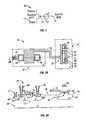
- FIG. 1is a conceptual circuit model of a pFET floating-gate transistor in accordance with one embodiment of the present invention.
- FIG. 2Ais a layout view of a pFET floating-gate transistor in accordance with one embodiment of the present invention.
- FIG. 2Bis a vertical cross-sectional view of a pFET floating-gate transistor taken along line 2 B— 2 B of FIG. 2 A.
- FIG. 2Cis a band diagram of a pFET floating-gate transistor in accordance with FIG. 2 A.
- FIG. 3is a system block diagram of a digital-to-analog converter (DAC) in accordance with an embodiment of the present invention.
- DACdigital-to-analog converter
- FIG. 4is a simplified electrical schematic diagram of a current-steering DAC in accordance with an embodiment of the present invention.
- FIG. 5is an electrical schematic diagram of one embodiment of a current trim cell in accordance with one embodiment of the present invention.
- FIG. 6is a process flow diagram illustrating a procedure for trimming the binary bits of a DAC in accordance with an embodiment of the present invention.
- FIG. 7is an electrical schematic diagram of one embodiment of a generic calibration system in accordance with an embodiment of the present invention.
- FIG. 8is a process flow diagram illustrating a procedure for trimming the bits of a generic device in accordance with the schematic diagram of FIG. 7 .
- FIG. 9is an electrical schematic diagram of a voltage trim cell in accordance with one embodiment of the present invention to be used in accordance with the embodiment of FIGS. 7 and 8 when voltage is the electrical parameter to be trimmed.
- FIG. 10Ais an electrical schematic diagram of a capacitance trim cell in accordance with one embodiment of the present invention to be used in accordance with the embodiment of FIGS. 7 and 8 when capacitance is the electrical parameter to be trimmed.
- FIG. 10Bis a side elevational cross-sectional diagram of the capacitance trim cell of FIG. 10A implemented in a p ⁇ doped substrate.
- FIGS. 10C , 10 D and 10 Eare side elevational cross-sectional diagrams of alternative embodiments of capacitive trim cells in accordance with the present invention.
- FIG. 11is a side elevational drawing of a resistance trim cell in accordance with one embodiment of the present invention to be used in accordance with the embodiment of FIGS. 7 and 8 when resistance is the electrical parameter to be trimmed.
- Embodiments of the present inventionare described herein in the context of a method and apparatus implementing a top-down calibration procedure in a trimmable electronic circuit comprising elements that require scaled matching for optimal performance.
- Those of ordinary skill in the artwill realize that the following detailed description of the present invention is illustrative only and is not intended to be in any way limiting. Other embodiments of the present invention will readily suggest themselves to such skilled persons having the benefit of this disclosure.
- the present inventionis applicable to any electronic circuit that requires scaled matching of some or all of its internal devices.
- Examples of circuits that can benefit from the present inventioninclude the following:
- the present inventioncan be used to match successive device outputs according to a desired scale factor, proceeding top-down from larger devices to smaller, thereby successively shrinking the cross-device errors which accrue during the matching process.
- the trimming algorithm and circuitrymust be contained either on-chip, or located in nearby chips.
- Bugej a, et aldemonstrated a trimming method in their paper A Self-Trimming 14b 100 Msample/s CMOS ADC , Proceedings of I.E.E.E. ISSCC 2000, pp. 44-45 (2000).
- a trim DAC and highly oversampled delta-sigma modulatorwere used to adjust only the unary thermometer-decoded MSB segments. This approach required a large amount of area to accommodate the measurement and comparison circuitry used to trim the MSBs.
- the trimming algorithmshould use a single comparator (or a small number of comparators) rather than high-resolution measurement circuitry. Also, the algorithm should be sufficiently simple that it can be implemented on chip.
- Existing trim proceduresare typically bottom-up (IMPJ-003, patent application Ser. No. 09/929,652): First the 2 sb is compared to the sum of two LSBs using a single comparator; if the 2 sb is too large or too small, it is trimmed down or up, respectively. Then the 3 sb is compared to the sum of two LSBs plus the trimmed 2 sb ; if the 3 sb is too large or too small, it is trimmed down or up, respectively.
- the present inventionsets forth a new top-down trim procedure and a corresponding trim circuit that do not require analog division, thereby enabling top-down trim in digital-to-analog converters.
- This inventionis generally applicable to current- steering digital-to-analog converters and similar devices that make use of scaled matching of components.
- the present inventionhas a number of advantages when compared with other trimming methods: the invention achieves the high accuracy of factory trimming methods, without their higher processing costs and their inability to compensate for changes in field operating conditions; and, compared with other post-factory trimming methods, the invention uses relatively simple on-chip circuitry to perform its trimming process.
- Floating-gate transistorsare used herein in the trim cells. These transistors are conventional transistors with the following additional attributes: (1) nonvolatile analog weight storage, (2) locally computed bidirectional weight updates, and (3) simultaneous memory reading and writing. Such transistors are described, for example, in U.S. Pat. Nos. 5,627,392; 5,825,063 and 5,898,613 to Diorio et al. P-channel floating-gate MOSFETs (pFETs) are used in accordance with one embodiment of the present invention.
- pFETsP-channel floating-gate MOSFETs
- pFET floating-gate transistorsuse charge stored on a floating gate to represent the nonvolatile analog weight, electron tunneling and hot-electron injection to modify the stored charge bidirectionally, and allow simultaneous memory reading and writing by nature of the mechanisms used to write the memory.
- the pFET floating-gate transistoris discussed in detail herein because of its inherent compatibility with standard CMOS processing.
- Other types of floating-gate transistorssuch as nFETs
- other charge storage and transport mechanismscould also be used as will now be appreciated by those of ordinary skill in the art.
- FIG. 1A conceptual circuit model 10 for a pFET floating-gate transistor 10 is illustrated in FIG. 1 . Electron tunneling and injection modify the gate offset voltage V q .
- FIG. 2 AA layout view of an example of one embodiment of this transistor is illustrated in FIG. 2 A.
- FIG. 2 BA cross-sectional view taken along line 2 B— 2 B of the transistor 11 of FIG. 2A is illustrated in FIG. 2 B and the band diagram for the transistor 11 is illustrated in FIG. 2 C.
- the transistor 11comprises two MOSFETs: the first is a readout transistor 12 ; the second, with shorted drain and source, forms a tunneling junction 14 .
- the floating gate 16is disposed over both readout transistor 12 and tunneling junction 14 .
- the transistor 11in accordance with one embodiment of the present invention primarily uses Fowler-Nordheim (FN) tunneling to remove electrons from its floating gate 16 , and impact-ionized hot-electron injection (IHEI) to add electrons to the floating gate 16 .
- FNFowler-Nordheim
- IHEIimpact-ionized hot-electron injection
- the floating-gate transistors used in this embodimentare used as current sources, there is no need for a gate input, accordingly, the version of the floating-gate transistor shown in FIGS. 2A , 2 B and 2 C lacks a control gate and hence obviates the need for a second layer of highly-doped polycrystalline silicon (poly 2 ) ensuring compatibility with standard digital CMOS processing. Where such a control gate is required, it may, of course, be provided.
- the pFET transistor 11is formed in a p ⁇ doped substrate 20 (doping level on the order of 10 17 atoms/cc) although those of ordinary skill in the art will now realize that it could as easily be formed as a thin film transistor (TFT) above the substrate, or on an insulator (SOI) or on glass (SOG). Essentially, any process capable of forming pFETs and nFETs will work.
- substrate 20are formed a first n ⁇ doped well 22 (doping level on the order of 10 17 atoms/cc) and a second n ⁇ doped well 24 (doping level on the order of 10 17 atoms/cc).
- first n ⁇ well 22are formed a pair of p+ doped regions 26 , 28 which may be diffusions or implants (doping level on the order of 10 21 atoms/cc) which form, respectively, the source 26 and drain 28 of readout transistor 12 .
- a channel 30is formed between source 26 and drain 28 .
- Over channel 30is disposed a high quality gate oxide (typically SiO 2 ) 32 of a thickness commensurate with the voltages to be used in the application.
- the gate oxide 32has a thickness in a range of about 70 angstroms to about 110 angstroms in the region above the channel 30 .
- Over gate oxide layer 32 above channel 30is disposed floating gate 16 .
- drain 28When drain 28 has a sufficiently negative voltage relative to source 26 , positively charged holes will be accelerated in channel 30 toward drain 28 and will impact with the crystalline lattice in the region of drain 28 creating an electron-hole pair. The electron is then repelled by the relatively negative drain are thereby injected (34) across the gate oxide layer 32 onto floating gate 16 .
- second n ⁇ doped well 24is formed a “shorted” pFET 35 , i.e., a pFET with its drain 36 and source 38 preferably shorted together with a metal or heavily-doped polycrystalline silicon conductor 40 .
- conductor 40overlies floating gate 16 in the region of tunneling junction 14 as shown.
- An n+ region 42(doping level on the order of 10 21 atoms/cc) is formed in n ⁇ well 24 and is also preferably (but not necessarily) shorted to drain 36 and source 38 by conductor 40 . Tunneling occurs between floating gate 16 and n ⁇ well 24 in region 43 as shown when a sufficiently positive voltage is applied to n ⁇ well 24 via n+ region 42 .
- a source contact terminal 44 , a drain contact terminal 46 and an n+ region contact terminal 48are provided.
- a well contact terminal 47 coupled to an n+ region 49 (doping level on the order of 10 21 atoms/cc) in n ⁇ well 22may also be provided. It should generally be tied to a source of positive potential. It may be strapped to the source 26 .
- the tunneling junction 14comprises a shorted pFET in an n ⁇ well for two primary reasons.
- a lightly-doped n ⁇ wellcan accommodate relatively high positive voltage without pn-junction breakdown to the substrate.
- a shorted pFET in an n ⁇ wellis a valid structure (that is, it satisfies the design rules) in any CMOS process.
- the floating-gate transistor 11 illustrated at FIGS. 2A , 2 B and 2 CKey features of the floating-gate transistor 11 illustrated at FIGS. 2A , 2 B and 2 C are (a) the readout transistor 12 remains a fully functional p-channel MOSFET; (b) relatively high voltages applied to the tunneling junction 14 tunnel electrons off the floating gate 16 ; (c) relatively large drain-to-source ( 26 to 28 ) voltages cause IHEI at the drain 28 , injecting electrons onto the floating gate 16 . Those of ordinary skill in the art will now realize that other mechanisms for injecting charge onto the floating gate may also be used, including tunneling.
- FIG. 3is a block diagram of a DAC 50 built in accordance with one embodiment of the present invention.
- a segmented current-source architecturewith L ( 11 ) binary-decoded LSBs (least significant bits) (LSB) and N ( 4 ) thermometer-decoded MSBs (most significant bits) is used.
- the on-hip calibration circuitry(not shown) trims the current sources in the LSB and MSB segments.
- the LSB segmentalso includes an extra LSB current-source 52 (discussed below), used for calibration.
- the lower 10 input bitsdrive binary-weighted current-source arrays ( 10 LSB), while the upper 4 bits are thermometer decoded with conventional thermometer decoder 56 to drive 15 identical current sources.
- the DAC 50features a-differential current output: each bit of the digital register controls a switch that steers the output from each current source in LSB and MSB to one of the two output terminals 58 , 60 .
- the approach shown in FIG. 3is designed to achieve 14-bit resolution (1 in 16384) without the need for intrinsically matched current sources.
- the LSB current sourcesare digitally decoded (i.e., 1, 2, 4, 8, etc.) and the MSB current sources are thermometer decoded (i.e., 0000, 0001, 0011, 0111, etc.) and may use smaller devices and simpler layouts to reduce die size.
- FIG. 4is a simplified electrical schematic diagram of a current-steering DAC in accordance with one embodiment of the present invention.
- Binary switches S I -S jwith their switch settings based on the input digital word 62 (the bits of which are denoted b 1 , b 2 , . . . , bj), steer current from an array of binary-weighted current sources C 1 , C 2 , . . . , Cj, to one of two outputs.
- b jis the j th bit of the digital input word, and switches the output from a current source of value 2 j *I, 0 ⁇ j ⁇ N ⁇ 1.
- Iis the current associated with the least significant bit b 1 .
- Nis the total number of current sources to be trimmed.
- each current source in the DAChas an associated trim cell (denoted T/C).
- T/Ctrim cell
- the trim cellbidirectionally adjusts the current source's output by either adding or subtracting a trim current.
- Each trim cellcontains a current mirror to optionally double the trim current, so that it operates in one of two modes: 1 ⁇ (normal) or 2 ⁇ (outputs twice the trim current). The trim cells will be discussed in more detail below.
- the designis segmented into a binary-decoded section and a thermometer-decoded section.
- the binary sectiontakes the least-significant bits of the inputs and uses binary-weighted current-sources as described above.
- the thermometer sectiontakes the most significant bits and runs them through a thermometer decoder.
- the resulting thermometer bitscontrol an array of current sources of equal magnitude. Each of these current sources has a magnitude of twice the value of the largest current source in the binary section.
- the algorithm presented herecan trim the binary section of such a DAC, using one of the thermometer current sources as the reference I R .
- thermometer current sourcesTrimming the thermometer current sources using the same trim cells discussed above is easily implemented, because all of the thermometer current sources arc to be calibrated to an identical value.
- thermometer decoderWith a thermometer decoder with a one-hot output option, which selects only one current source at a time. The selected current source can easily be trimmed by comparing its output to a reference current source.
- a reference current sourcecould be set, for example, to the median value of all thermometer current sources.
- FIG. 5is an electrical schematic diagram of one embodiment of a trim cell in accordance with the present invention.
- the trim cell 80is adapted to produce an output current I Ti which is added to the output current I i from current source C i .
- the circuit of FIG. 5is not the only circuit that will perform this function, it is simply an example of one that will work. Those of ordinary skill in the art will now realize that many other circuits will work to perform the functions described for the circuit of FIG. 5 .
- the tunneling junction 82removes electrons from the floating gate 84 as described above.
- Injection transistor 86injects electrons onto floating gate 84 as described above.
- the current mirror circuit 88provides a 1 ⁇ current output when the DBL input 90 is equal to the VDA input 92 (i.e., pMOS transistor M 19 is off) and a 2 ⁇ current output when DBL input 90 is 0 (ground GND 94 ).
- VDAis the supply voltage
- BIAS, VRG, CGN and TREFare DC bias voltage inputs generated by a global bias voltage supply circuit (not shown).
- VTUNis the tunneling voltage and is connected to VDA to disable tunneling.
- VTRMis the injection supply voltage and is normally connected to VDA. Both EJ and VINJ are injection must be set to the logic zero state ( ⁇ 2.5 V nominal in this embodiment) in order to enable injection.
- the drain current of PMOS current source transistor M 1is controlled by floating gate node FG ( 84 ).
- PMOS transistor M 2 located in series with the source of M 1is operated in the triode region as a variable resistor to provide temperature compensation for the trimmed drain current of M 1 .
- the drain current of M 1is the input current to the NMOS current mirror circuit including transistors M 6 , M 7 , M 26 , M 28 and M 24 .
- Cascode transistors M 3 , M 8 , M 25 , M 27 and M 23are used to increase the output impedance of the current source transistors in accordance with this particular embodiment and are not essential for circuit operation.
- the drain current of the NMOS current mirror circuitis equal in magnitude, but opposite in direction, to the drain current of M 1 when the DBL input voltage is equal to VDA.
- PMOS switch transistor M 19When the DBL input voltage is zero (GND), PMOS switch transistor M 19 is turned on and the drain current magnitude of the NMOS current mirror circuit is doubled.
- the output current of the trim cellis provided at the node labeled OUT.
- the drain current of the NMOS current mirror at node N 6will flow through switch M 5 into the PMOS current mirror of M 21 and M 22 , and the trim cell output current will be equal to the drain current of M 22 .
- the drain current of the NMOS current mirror at node N 6will flow through switch M 4 directly to the trim cell output node OUT.
- the reference current I Rcan easily be obtained by first trimming the thermometer current sources to a common value, and then using one of the trimmed thermometer current sources as the reference current I R .
- the trim procedureis illustrated in FIG. 6 , a process flow diagram.
- thermometer sectiontrim each thermometer current source to the median value of all thermometer current sources ( 120 ), and use one of the trimmed thermometer current sources as the reference current I R ( 121 ).
- trim cell outputis now 2 (I Ti ) ( 128 ).
- FIG. 4shows an implementation using an auto-zeroing comparator 64 with a single-ended current input 66 .
- the calibration measurementis made by alternating the DAC output between the reference current I R and the measured current.
- the comparatoris auto-zeroed when the reference current is applied to its input 66 .
- the comparatorstores the reference current during the auto-zero phase, and then compares this stored reference current level to the measured current during the measurement phase.
- the comparator digital output 68indicates whether the measured current was greater than or less than the reference current.
- the comparator output 68is used to control the calibration state machine logic (not shown). During normal DAC operation the DAC output is disconnected from the comparator by opening switch SS 3 and closing switch SS 2 .
- Extra current-source element b xcan be disconnected from the DAC for normal operation by opening switch SS 4 .
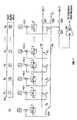
- FIG. 7is an electrical schematic diagram of one embodiment of a generic calibration system in accordance with an embodiment of the present invention.
- An input word 140 having bits b i through b Nprovides a value to be converted to an output of some parameter (e.g., voltage, current, capacitance, resistance).
- Cells C 1 through C jprovide relatively fixed values of the parameter corresponding to their bit positions.
- Trim cells, denoted T/C 1 through T/C jprovide adjustable values of the parameter and may be trimmed by F-N tunneling to reduce the charge on a floating gate controlling the adjustable value of the parameter and IHEI to increase it.
- Cell outputs and trim cell outputsare summed in a series of combiners 142 - 1 , 142 - 2 , . . . , 142 - j . Outputs of these combiners are directed to the inputs of switches S 1 through S j . Switches S 1 through S j output to either a first bus 144 or a second bus 146 depending on the state of corresponding bit b j .
- additional buses and multi-state switchesmay be provided as will now be apparent to those of ordinary skill in the art.
- An additional x-bitis provided and controlled as before and includes a cell C x , a trim cell T/C x and a switch S x .
- the x-bitmay be decoupled from both busses via switch SS 4 .
- a comparator 148is provided. In the example shown it is an auto-zeroing comparator, however, other types of comparators could be used with fixed references to establish the calibration.
- FIG. 8is a process flow diagram illustrating a procedure 158 for trimming the bits of a generic device in accordance with the schematic diagram of FIG. 7 .
- FIG. 8corresponds with FIG. 6 of the DAC embodiment.
- the steps 160 - 176 of FIG. 8correspond exactly with steps 120 - 132 of FIG. 6 except that in FIG. 8 the generic parameter “P” is used instead of current “I” as in FIG. 6 .
- FIG. 9is an electrical schematic diagram of a voltage trim cell 180 in accordance with one embodiment of the present invention to be used in accordance with the embodiment of FIGS. 7 and 8 when voltage is the electrical parameter to be trimmed.
- the negative charge on floating gate 182is increased by injecting electrons onto floating gate 182 with injector 184 . It is decreased by tunneling electrons off of floating gate 182 with tunneling junction 186 .
- Amplifier 188provides an output at node VOUT in a conventional manner.
- FIG. 10Ais an electrical schematic diagram of a capacitance trim cell 190 in accordance with one embodiment of the present invention to be used in accordance with the embodiment of FIGS. 7 and 8 when capacitance is the electrical parameter to be trimmed.
- FIG. 10Bis a side elevational cross-sectional diagram of the capacitance trim cell of FIG. 10 A.
- FIGS. 10C , 10 D and 10 Eare side elevational cross-sectional diagrams of capacitive trim cells in accordance with alternative embodiments of the present invention.
- the MOS floating gate variable capacitor 190is a circuit comprising at least four devices. These are labeled M 1 , M 2 , M 3 and M 4 . M 1 , M 2 , M 3 and M 4 all share the same floating gate 192 formed from a poly 1 layer (heavily doped conductive polysilicon). M 1 and M 2 are a pair of relatively large (9 ⁇ m ⁇ 9 ⁇ m) pFET transistors as described above.
- M 1 and M 2are designed to be substantially larger than M 3 and M 4 and to have correspondingly larger capacitance so that the parasitic capacitance effects of M 3 and M 4 are overwhelmed by the much larger capacitance of M 1 and M 2 .
- capacitanceis a function of area
- the example shown in FIG. 10Ahas the area of the M 1 and M 2 capacitors being approximately 500 times the area of the M 3 and M 4 capacitors.
- the transistor pair M 1 , M 2 and the transistor pair M 3 , M 4should be substantially the same size as one another and may be connected so that drain, source and well contact are coupled together as shown. Two or more of these devices can be series connected as shown in order to reduce nonlinearity caused by non-uniformity of fabricated devices. In many cases, two (as shown) will be sufficient.
- M 3is a tunneling junction device with drain, source and well contact coupled together as shown. It need not be as large as M 1 and M 2 and, in one embodiment, may be 0.24 ⁇ m ⁇ 0.60 ⁇ m.
- M 4is an injection device of similar size to device M 3 configured as described above.
- the MOS floating gate variable capacitor 190has five terminals: Vtun (the tunneling voltage); Vinj (the injection voltage); Bias (the bias voltage applied to the injector M 4 ); Cap_In and Cap_Out (the terminals across which the variable capacitance appears).
- the tunneling junction M 3comprises a shorted pFET in an n ⁇ well for two primary reasons.
- a lightly-doped n ⁇ wellcan accommodate relatively high positive voltage without pn-junction breakdown to the substrate.
- a shorted pFET in an n ⁇ wellis a valid structure (that is, it satisfies the design rules) in any CMOS process.
- MOS floating gate variable capacitor 190Key features of the MOS floating gate variable capacitor 190 are: (a) relatively high voltages applied to the tunneling junction M 3 tunnel electrons off the common floating gate 192 ; (b) relatively large drain-to-source voltages at M 4 cause IHEI at the drain of M 4 , injecting electrons onto the common floating gate 192 .
- Those of ordinary skill in the artwill now realize that other mechanisms for injecting charge onto the floating gate may also be used, including tunneling.
- the large value capacitors M 1 and M 2are biased either in inversion or accumulation. By varying the amount of floating-gate charge, the total series capacitance of M 1 and M 2 may be adjusted by changing the voltage across the individual capacitors. In this manner, two capacitors may be adjusted to set their values equal to one another.
- Electron injectionis induced by applying a negative voltage (e.g., ⁇ 2.5 V) to M 4 's drain.
- the power supplymay be located either off-chip or on-chip and provided by conventional on-chip charge pumps.
- connection 194 , 196 , 198 , 200 and 202as shown in FIGS. 10B , 10 C and 10 D.
- FIG. 10Can alternative embodiment of the present invention is illustrated.
- the capacitorsoperate in the accumulation region and thus do not require source or drain regions.
- the capacitanceappears between the common floating gate 192 and the wells 204 and 206 , respectively.
- the deviceoperates as described above in conjunction with FIG. 10 B.
- FIG. 10Dyet another alternative embodiment of the present invention is illustrated.
- the substrateis p ⁇ doped
- the wellsare all n ⁇ doped and the well, source and drain contacts are all n+ doped (the well contact may be omitted).
- Heavily doped n ⁇ type polyis used for the floating gate. This embodiment will work as well for variable capacitor elements.
- FIG. 10Eanother alternative embodiment of the present invention is illustrated.
- a MOS device M 1forms a first capacitor having one plate in the well 212 of MOS device M 1 and a second plate at the floating gate 214 .
- a second capacitoris formed between a second gate formed in the poly 2 layer 216 and the common floating gate 214 .
- the two capacitorsare series connected at the floating gate and charge transport onto and off of the floating gate is handled as in the device illustrated at FIG. 5 A and discussed above.
- the capacitance between the first polysilicon layer and the second polysilicon layerremains fixed and only the capacitance between the first polysilicon layer and the well is variable.
- the capacitance across the two capacitor plates, comprised of the well connection 218 of transistor M 1 and the second polysilicon layer 216remains variable. Note that this embodiment may also be modified along the lines of the embodiment shown in FIG. 10C (source and drain on the capacitor devices omitted) and discussed above.
- conventional metalizationprovides the connections 220 , 222 , 224 and 226 shown in FIG. 5 E.
- FIG. 11is a side elevational drawing of a resistance trim cell 230 in accordance with one embodiment of the present invention to be used in accordance with the embodiment of FIGS. 7 and 8 when resistance is the electrical parameter to be trimmed.
- Resistance appearing between nodes 232 and 234is adjusted by varying the negative charge on floating gate 236 using tunneling to remove electrons and injection to add electrons.
- silicon dioxideSiO 2
- SiO 2silicon dioxide
- other dielectric materialsmay be used alone, or in combination with silicon dioxide.
- any of the followingcould also be used: nitrided oxide, nitride, oxide/nitride composite, titanium oxide, tantalum oxide, zirconium oxide, hafnium oxide, lanthanum oxide (or any oxide of a lanthanide), titanium silicate, tantalum silicate, zirconium silicate, hafnium silicate and lanthanum silicate (or any silicate of a lanthanide) and composite or multilayer structures thereof.
- These alternative dielectricsgenerally provide higher dielectric constants and can therefore be utilized in thinner layers than silicon dioxide.
- floating gates referred to hereinmay include conductive polysilicon as well as “metals” such as aluminum, copper, titanium, and the like.
- n ⁇ wellas used herein is intended to encompass not only conventional n ⁇ well devices, but also NLDD (N-type Lightly Doped Drain) devices and other lightly doped, or isolated structures that increase the reliable gate-drain and drain-source voltages of the device so that it, in effect, behaves like a conventional n ⁇ well device in this respect.
- NLDDN-type Lightly Doped Drain
Landscapes
- Physics & Mathematics (AREA)
- Nonlinear Science (AREA)
- Engineering & Computer Science (AREA)
- Theoretical Computer Science (AREA)
- Analogue/Digital Conversion (AREA)
Abstract
Description
Examples of circuits that can benefit from the present invention include the following:
- 1) A current-steering digital-to-analog converter (DAC) which may contain an internal array of transistor-based current sources which are intended to emit scaled multiples of some base reference value (1×, 2×, 4×, 8×, etc.), in order to produce an analog current output which accurately reflects an input digital code word;
- 2) A voltage-controlled oscillator (VCO) which may contain an internal array of capacitor-based voltage sources which are intended to emit scaled multiples of some base reference value, in order to produce a specific analog voltage which in turn causes the VCO to deliver an output signal of a specific frequency; and
- 3) A voltage-steering digital-to-analog converter (DAC) which may contain an internal array of capacitor-based voltage sources which are intended to emit scaled multiples of some base reference value, in order to produce an analog voltage output which accurately reflects an input digital code word.
- IR=a reference current equal to twice the magnitude of the current source associated with bit bN.
- Ix=the total current associated with bit bx
- ITx=the trim current associated with bit bx
- IUithe untrimmed current source current for bi
- ITi=the trim current for bi
- Ii=IUi+ITiand is the total current associated with bit bi, the bit being trimmed (bits are numbered 1 (lowest order) to N (highest order))
- Σ(Ii−)=the sum of all binary weighted current sources (total currents) associated with bits of lower order than bi
- Σ(Ii+)=the sum of all binary weighted current sources (total currents) associated with bits of higher order than bi
Because: Σ(Ii−)+Ix=IUi, then 2IUi+2(ITi)+Σ(Ii+)=IR
ThusIi=IUi+ITi={IR−Σ(Ii+)}/2
Claims (55)
Priority Applications (1)
| Application Number | Priority Date | Filing Date | Title |
|---|---|---|---|
| US10/281,384US6909389B1 (en) | 2002-06-14 | 2002-10-24 | Method and apparatus for calibration of an array of scaled electronic circuit elements |
Applications Claiming Priority (2)
| Application Number | Priority Date | Filing Date | Title |
|---|---|---|---|
| US38926702P | 2002-06-14 | 2002-06-14 | |
| US10/281,384US6909389B1 (en) | 2002-06-14 | 2002-10-24 | Method and apparatus for calibration of an array of scaled electronic circuit elements |
Publications (1)
| Publication Number | Publication Date |
|---|---|
| US6909389B1true US6909389B1 (en) | 2005-06-21 |
Family
ID=34656688
Family Applications (1)
| Application Number | Title | Priority Date | Filing Date |
|---|---|---|---|
| US10/281,384Expired - LifetimeUS6909389B1 (en) | 2002-06-14 | 2002-10-24 | Method and apparatus for calibration of an array of scaled electronic circuit elements |
Country Status (1)
| Country | Link |
|---|---|
| US (1) | US6909389B1 (en) |
Cited By (20)
| Publication number | Priority date | Publication date | Assignee | Title |
|---|---|---|---|---|
| US20040195593A1 (en)* | 2002-09-16 | 2004-10-07 | Impinj, Inc., A Delaware Corporation | Counteracting overtunneling in nonvolatile memory cells |
| US20050030826A1 (en)* | 2002-09-16 | 2005-02-10 | Impinj, Inc., A Delaware Corporation | Method and apparatus for programming single-poly pFET-based nonvolatile memory cells |
| US20050030827A1 (en)* | 2002-09-16 | 2005-02-10 | Impinj, Inc., A Delaware Corporation | PMOS memory cell |
| US20050140449A1 (en)* | 2002-10-08 | 2005-06-30 | Impiji, Inc., A Delaware Corporation | Use of analog-valued floating-gate transistors for parallel and serial signal processing |
| US20060145744A1 (en)* | 2002-10-08 | 2006-07-06 | Impinj, Inc. | Use of analog-valued floating-gate transistors to match the electrical characteristics of interleaved and pipelined circuits |
| US20080205150A1 (en)* | 2004-04-21 | 2008-08-28 | Impinj, Inc. | Hybrid non-volatile memory |
| US7576667B1 (en)* | 2007-04-10 | 2009-08-18 | Marvell International Ltd. | Hierarchied calibration circuit |
| US20100141497A1 (en)* | 2008-12-09 | 2010-06-10 | Robit Yang | Decoder Architecture with Sub-Thermometer Codes for DACs |
| US20100164771A1 (en)* | 2006-02-21 | 2010-07-01 | Nxp B.V. | Exponential digital to analog converter |
| US8111558B2 (en) | 2004-05-05 | 2012-02-07 | Synopsys, Inc. | pFET nonvolatile memory |
| US8122307B1 (en) | 2006-08-15 | 2012-02-21 | Synopsys, Inc. | One time programmable memory test structures and methods |
| US8139411B1 (en) | 2008-05-22 | 2012-03-20 | Synopsys, Inc. | pFET nonvolatile memory |
| US8422294B2 (en) | 2010-10-08 | 2013-04-16 | Infineon Technologies Ag | Symmetric, differential nonvolatile memory cell |
| US8456910B2 (en) | 2010-07-30 | 2013-06-04 | Infineon Technologies Ag | Nonvolatile memory cell with well extending under transistor and data storage capacitor of memory cell |
| US8503568B1 (en)* | 2006-09-07 | 2013-08-06 | The Boeing Company | Differential encoding for multiplexed data streams |
| US8690057B2 (en) | 2012-03-06 | 2014-04-08 | A-I Packaging Solutions, Inc. | Radio frequency identification system for tracking and managing materials in a manufacturing process |
| US10581448B1 (en)* | 2018-05-28 | 2020-03-03 | Ali Tasdighi Far | Thermometer current mode analog to digital converter |
| US11023851B2 (en) | 2018-03-30 | 2021-06-01 | A-1 Packaging Solutions, Inc. | RFID-based inventory tracking system |
| US11348067B2 (en) | 2018-03-30 | 2022-05-31 | A-1 Packaging Solutions, Inc. | RFID-based inventory tracking system |
| US11443158B2 (en) | 2019-04-22 | 2022-09-13 | A-1 Packaging Solutions, Inc. | Easily attachable RFID tag and method of making the same |
Citations (39)
| Publication number | Priority date | Publication date | Assignee | Title |
|---|---|---|---|---|
| US3958236A (en) | 1974-12-18 | 1976-05-18 | Weston Instruments, Inc. | Offset control in autozeroing circuits for analog-to-digital converters |
| US4037242A (en) | 1975-12-29 | 1977-07-19 | Texas Instruments Incorporated | Dual injector, floating gate MOS electrically alterable, non-volatile semiconductor memory device |
| US4763105A (en) | 1987-07-08 | 1988-08-09 | Tektronix, Inc. | Interleaved digitizer array with calibrated sample timing |
| US4783783A (en) | 1985-07-29 | 1988-11-08 | Hitachi, Ltd. | Data processing system having pipeline arithmetic/logic units |
| US4864215A (en) | 1988-02-16 | 1989-09-05 | U.S. Philips Corp. | Current source arrangement |
| US4914440A (en)* | 1987-09-21 | 1990-04-03 | Sgs-Thomson Microelectronics S.A. | Adjustable current source and digital/analog converter with autocalibration using such a source |
| US4935702A (en) | 1988-12-09 | 1990-06-19 | Synaptics, Inc. | Subthreshold CMOS amplifier with offset adaptation |
| US5059920A (en) | 1988-12-09 | 1991-10-22 | Synaptics, Incorporated | CMOS amplifier with offset adaptation |
| US5068622A (en) | 1988-12-09 | 1991-11-26 | Synaptics, Incorporated | CMOS amplifier with offset adaptation |
| US5146106A (en) | 1988-12-09 | 1992-09-08 | Synaptics, Incorporated | CMOS winner-take all circuit with offset adaptation |
| US5166562A (en) | 1991-05-09 | 1992-11-24 | Synaptics, Incorporated | Writable analog reference voltage storage device |
| US5243347A (en) | 1992-09-28 | 1993-09-07 | Motorola, Inc. | Monotonic current/resistor digital-to-analog converter and method of operation |
| US5332997A (en) | 1992-11-04 | 1994-07-26 | Rca Thomson Licensing Corporation | Switched capacitor D/A converter |
| US5376935A (en)* | 1993-03-30 | 1994-12-27 | Intel Corporation | Digital-to-analog and analog-to-digital converters using electrically programmable floating gate transistors |
| US5627392A (en) | 1995-03-07 | 1997-05-06 | California Institute Of Technology | Semiconductor structure for long term learning |
| US5666118A (en) | 1995-03-06 | 1997-09-09 | International Business Machines Corporation | Self calibration segmented digital-to-analog converter |
| US5710563A (en) | 1997-01-09 | 1998-01-20 | National Semiconductor Corporation | Pipeline analog to digital converter architecture with reduced mismatch error |
| US5790060A (en) | 1996-09-11 | 1998-08-04 | Harris Corporation | Digital-to-analog converter having enhanced current steering and associated method |
| US5793231A (en)* | 1997-04-18 | 1998-08-11 | Northern Telecom Limited | Current memory cell having bipolar transistor configured as a current source and using field effect transistor (FET) for current trimming |
| US5825063A (en) | 1995-03-07 | 1998-10-20 | California Institute Of Technology | Three-terminal silicon synaptic device |
| US5825317A (en)* | 1997-04-07 | 1998-10-20 | Motorola, Inc. | Digital-to-analog converter and method of calibrating |
| US5841384A (en) | 1994-08-18 | 1998-11-24 | Hughes Electronics | Non-linear digital-to-analog converter and related high precision current sources |
| US5870044A (en) | 1996-11-14 | 1999-02-09 | Sgs-Thomson Microelectronics S.A. | Digital analog converter with self-calibration current sources |
| US5898613A (en) | 1996-07-24 | 1999-04-27 | California Institute Of Technology | pMOS analog EEPROM cell |
| US5933039A (en) | 1992-12-07 | 1999-08-03 | Dallas Semiconductor Corporation | Programmable delay line |
| US5939945A (en) | 1996-07-25 | 1999-08-17 | Siemens Aktiengesellschaft | Amplifier with neuron MOS transistors |
| US5952946A (en) | 1997-09-30 | 1999-09-14 | Stmicroelectronics, S.R.L. | Digital-to-analog charge converter employing floating gate MOS transisitors |
| US5955980A (en) | 1997-10-03 | 1999-09-21 | Motorola, Inc. | Circuit and method for calibrating a digital-to-analog converter |
| US6118398A (en) | 1998-09-08 | 2000-09-12 | Intersil Corporation | Digital-to-analog converter including current sources operable in a predetermined sequence and associated methods |
| US6130632A (en) | 1998-04-16 | 2000-10-10 | National Semiconductor Corporation | Digitally self-calibrating current-mode D/A converter |
| US6134182A (en) | 1999-10-19 | 2000-10-17 | International Business Machines Corporation | Cycle independent data to echo clock tracking circuit |
| US6169503B1 (en) | 1998-09-23 | 2001-01-02 | Sandisk Corporation | Programmable arrays for data conversions between analog and digital |
| US6191715B1 (en) | 1998-10-29 | 2001-02-20 | Burr-Brown Corporation | System for calibration of a digital-to-analog converter |
| US20010020861A1 (en) | 2000-03-08 | 2001-09-13 | Yukitoshi Hirose | Delay circuit |
| US6317066B1 (en) | 2000-03-09 | 2001-11-13 | Sunplus Technology Co., Ltd. | Layout arrangement of current sources in a current-mode digital-to-analog converter |
| US6320788B1 (en) | 1998-09-25 | 2001-11-20 | Sandisk Corporation | Programmable impedance device |
| US20010054920A1 (en) | 2000-06-27 | 2001-12-27 | Mitsubishi Denki Kabushiki Kaisha | Semiconductor device capable of internally adjusting delayed amount of a clock signal |
| US20020089440A1 (en) | 1999-04-22 | 2002-07-11 | Christian Kranz | Digital GMSK filter |
| US6583740B2 (en)* | 2001-11-21 | 2003-06-24 | Analog Devices, Inc. | Calibrated current source |
- 2002
- 2002-10-24USUS10/281,384patent/US6909389B1/ennot_activeExpired - Lifetime
Patent Citations (40)
| Publication number | Priority date | Publication date | Assignee | Title |
|---|---|---|---|---|
| US3958236A (en) | 1974-12-18 | 1976-05-18 | Weston Instruments, Inc. | Offset control in autozeroing circuits for analog-to-digital converters |
| US4037242A (en) | 1975-12-29 | 1977-07-19 | Texas Instruments Incorporated | Dual injector, floating gate MOS electrically alterable, non-volatile semiconductor memory device |
| US4783783A (en) | 1985-07-29 | 1988-11-08 | Hitachi, Ltd. | Data processing system having pipeline arithmetic/logic units |
| US4763105A (en) | 1987-07-08 | 1988-08-09 | Tektronix, Inc. | Interleaved digitizer array with calibrated sample timing |
| EP0298618A2 (en) | 1987-07-08 | 1989-01-11 | Tektronix Inc. | Interleaved digitizer array with calibrated sample timing |
| US4914440A (en)* | 1987-09-21 | 1990-04-03 | Sgs-Thomson Microelectronics S.A. | Adjustable current source and digital/analog converter with autocalibration using such a source |
| US4864215A (en) | 1988-02-16 | 1989-09-05 | U.S. Philips Corp. | Current source arrangement |
| US5059920A (en) | 1988-12-09 | 1991-10-22 | Synaptics, Incorporated | CMOS amplifier with offset adaptation |
| US4935702A (en) | 1988-12-09 | 1990-06-19 | Synaptics, Inc. | Subthreshold CMOS amplifier with offset adaptation |
| US5068622A (en) | 1988-12-09 | 1991-11-26 | Synaptics, Incorporated | CMOS amplifier with offset adaptation |
| US5146106A (en) | 1988-12-09 | 1992-09-08 | Synaptics, Incorporated | CMOS winner-take all circuit with offset adaptation |
| US5166562A (en) | 1991-05-09 | 1992-11-24 | Synaptics, Incorporated | Writable analog reference voltage storage device |
| US5243347A (en) | 1992-09-28 | 1993-09-07 | Motorola, Inc. | Monotonic current/resistor digital-to-analog converter and method of operation |
| US5332997A (en) | 1992-11-04 | 1994-07-26 | Rca Thomson Licensing Corporation | Switched capacitor D/A converter |
| US5933039A (en) | 1992-12-07 | 1999-08-03 | Dallas Semiconductor Corporation | Programmable delay line |
| US5376935A (en)* | 1993-03-30 | 1994-12-27 | Intel Corporation | Digital-to-analog and analog-to-digital converters using electrically programmable floating gate transistors |
| US5841384A (en) | 1994-08-18 | 1998-11-24 | Hughes Electronics | Non-linear digital-to-analog converter and related high precision current sources |
| US5666118A (en) | 1995-03-06 | 1997-09-09 | International Business Machines Corporation | Self calibration segmented digital-to-analog converter |
| US5825063A (en) | 1995-03-07 | 1998-10-20 | California Institute Of Technology | Three-terminal silicon synaptic device |
| US5627392A (en) | 1995-03-07 | 1997-05-06 | California Institute Of Technology | Semiconductor structure for long term learning |
| US5898613A (en) | 1996-07-24 | 1999-04-27 | California Institute Of Technology | pMOS analog EEPROM cell |
| US5939945A (en) | 1996-07-25 | 1999-08-17 | Siemens Aktiengesellschaft | Amplifier with neuron MOS transistors |
| US5790060A (en) | 1996-09-11 | 1998-08-04 | Harris Corporation | Digital-to-analog converter having enhanced current steering and associated method |
| US5870044A (en) | 1996-11-14 | 1999-02-09 | Sgs-Thomson Microelectronics S.A. | Digital analog converter with self-calibration current sources |
| US5710563A (en) | 1997-01-09 | 1998-01-20 | National Semiconductor Corporation | Pipeline analog to digital converter architecture with reduced mismatch error |
| US5825317A (en)* | 1997-04-07 | 1998-10-20 | Motorola, Inc. | Digital-to-analog converter and method of calibrating |
| US5793231A (en)* | 1997-04-18 | 1998-08-11 | Northern Telecom Limited | Current memory cell having bipolar transistor configured as a current source and using field effect transistor (FET) for current trimming |
| US5952946A (en) | 1997-09-30 | 1999-09-14 | Stmicroelectronics, S.R.L. | Digital-to-analog charge converter employing floating gate MOS transisitors |
| US5955980A (en) | 1997-10-03 | 1999-09-21 | Motorola, Inc. | Circuit and method for calibrating a digital-to-analog converter |
| US6130632A (en) | 1998-04-16 | 2000-10-10 | National Semiconductor Corporation | Digitally self-calibrating current-mode D/A converter |
| US6118398A (en) | 1998-09-08 | 2000-09-12 | Intersil Corporation | Digital-to-analog converter including current sources operable in a predetermined sequence and associated methods |
| US6169503B1 (en) | 1998-09-23 | 2001-01-02 | Sandisk Corporation | Programmable arrays for data conversions between analog and digital |
| US6320788B1 (en) | 1998-09-25 | 2001-11-20 | Sandisk Corporation | Programmable impedance device |
| US6191715B1 (en) | 1998-10-29 | 2001-02-20 | Burr-Brown Corporation | System for calibration of a digital-to-analog converter |
| US20020089440A1 (en) | 1999-04-22 | 2002-07-11 | Christian Kranz | Digital GMSK filter |
| US6134182A (en) | 1999-10-19 | 2000-10-17 | International Business Machines Corporation | Cycle independent data to echo clock tracking circuit |
| US20010020861A1 (en) | 2000-03-08 | 2001-09-13 | Yukitoshi Hirose | Delay circuit |
| US6317066B1 (en) | 2000-03-09 | 2001-11-13 | Sunplus Technology Co., Ltd. | Layout arrangement of current sources in a current-mode digital-to-analog converter |
| US20010054920A1 (en) | 2000-06-27 | 2001-12-27 | Mitsubishi Denki Kabushiki Kaisha | Semiconductor device capable of internally adjusting delayed amount of a clock signal |
| US6583740B2 (en)* | 2001-11-21 | 2003-06-24 | Analog Devices, Inc. | Calibrated current source |
Non-Patent Citations (18)
| Title |
|---|
| Bastos, et al., "A 12-bit Intrinsic Accuracy High-Speed CMOS DAC", IEEE Journal of Solid-State Circuits, vol. 33, No. 12, Dec. 1998, pp. 1959-1969. |
| Bugeja, et al., "A 14-b, 100-MS/s CMOS DAC Designed for Spectral Performance", IEEE Journal of Solid-State Circuits, vol. 34, No. 12, Dec. 1999, pp. 1719-1732. |
| Bugeja, et al., "A Self-Trimming 14-b 100-MS/s CMOS DAC", IEEE Journal of Solid-State Circuits, vol. 35, No. 12, Dec. 2000, pp. 1841-1852. |
| Carley, L. Richard, "Trimming Analog Circuits Using Floating-Gate Analog MOS Memory", IEEE Journal of Solid-State Circuits, vol. 24, No. 6, pp. 1569-1575, Dec. 1989. |
| Diorio, et al., "A Floating-Gate MOS Learning Array with Locally Computed Weight Updates" IEEE Transactions on Electron Devices, vol. 44, No. 12, Dec. 1997, pp. 1-10. |
| Diorio, et al., "A High-Resolution Non-Volatile Analog Memory Cell", IEEE, 1995, pp. 2233-2236. |
| Diorio, et al., "Adaptive CMOS: From Biological Inspiration to Systems-on-a-Chip"; IEEE, vol. 90, No. 3; Mar. 2002; pp 345-357. |
| Hyde, et al.; "A Floating-Gate Trimmed, 14-Bit, 250 Ms/s Digital-to-Analog Converter in Standard 0.25 um CMOS", Impinj, 2002 Symposium on VLSI Circuits, Honolulu HI; pp 328-331. |
| Partial International Search for International Application No. PCT/US03/31792, date mailed Apr. 2, 2004. |
| Tille, et al., "A 1.8-V MOSFET-Only Sigma Delta Modulator Using Substrate Biased Depletion-Mode MOS Capacitors in Series Compensation", IEEE, Journal of Solid-State Circuits, vol. 36, No. 7, Jul. 2001, pp. 1041-1046. |
| Van der Plas, et al., "A 14-bit Instrinsic Accuracy Q<SUP>2 </SUP>Random Walk CMOS DAC", IEEE Journal of Solid-State Circuits, vol. 34, No. 12, Dec. 1999, pp. 1708-1718. |
| Vittoz, "Analog-Digital Conversion Techniques for Telecommunications Applications", Design of Analog-Digital VLSI Circuits for Telecommunications and Signal Processing, Chapter 9, 1994, pp. 289-315. |
| Vittoz, "Continuous-Time Filters", Design of Analog-Digital VLSI Circuits for Telecommunications and Signal Processing, Chapter 6, 1994, pp. 177-211. |
| Vittoz, "Delta-Sigma Data Converters", Design of Analog-Digital VLSI Circuits for Telecommunications and Signal Processing, Chapter 10, 1994, pp. 317-339. |
| Vittoz, "Dynamic Analog Techniques", Design of Analog-Digital VLSI Circuits for Telecommunications and Signal Processing, Chapter 4, 1994, pp. 97-124. |
| Vittoz, "Dynamic Analog Techniques", Design of MOS VLSI Circuits for Telecommunications, 1985, pp. 145-170. |
| Yoshio, Patent Abstract of Japan, "Multiple Semiconductor Variable Capacitance Element", Publication No.: 57188886, Publication date: Nov. 19, 1982. |
| Yoshizawa, et al., "MOSFET-Only Switched-Capacitor Circuits in Digital CMOS Technology", IEEE Journal of Solid-State Circuits, vol. 34, No. 6, Jun. 1999, pp. 734-747. |
Cited By (49)
| Publication number | Priority date | Publication date | Assignee | Title |
|---|---|---|---|---|
| US7573749B2 (en) | 2002-09-16 | 2009-08-11 | Virage Logic Corporation | Counteracting overtunneling in nonvolatile memory cells |
| US20070019476A1 (en)* | 2002-09-16 | 2007-01-25 | Impinj, Inc., A Delaware Corporation | Method and apparatus for programming single-poly pFET-based nonvolatile memory cells |
| US20050030827A1 (en)* | 2002-09-16 | 2005-02-10 | Impinj, Inc., A Delaware Corporation | PMOS memory cell |
| US20040195593A1 (en)* | 2002-09-16 | 2004-10-07 | Impinj, Inc., A Delaware Corporation | Counteracting overtunneling in nonvolatile memory cells |
| US20050030826A1 (en)* | 2002-09-16 | 2005-02-10 | Impinj, Inc., A Delaware Corporation | Method and apparatus for programming single-poly pFET-based nonvolatile memory cells |
| US7411829B2 (en) | 2002-09-16 | 2008-08-12 | Diorio Christopher J | Method and apparatus for programming single-poly pFET-based nonvolatile memory cells |
| US7411828B2 (en) | 2002-09-16 | 2008-08-12 | Diorio Christopher J | Method and apparatus for programming single-poly pFET-based nonvolatile memory cells |
| US7408809B2 (en) | 2002-09-16 | 2008-08-05 | Impinj, Inc. | Method and apparatus for programming single-poly pFET-based nonvolatile memory cells |
| US20070171724A1 (en)* | 2002-09-16 | 2007-07-26 | Impinj, Inc. | Counteracting overtunneling in nonvolatile memory cells |
| US7212446B2 (en)* | 2002-09-16 | 2007-05-01 | Impinj, Inc. | Counteracting overtunneling in nonvolatile memory cells using charge extraction control |
| US20070019475A1 (en)* | 2002-09-16 | 2007-01-25 | Impinj, Inc., A Delaware Corporation | Method and apparatus for programming single-poly pFET-based nonvolatile memory cells |
| US7149118B2 (en) | 2002-09-16 | 2006-12-12 | Impinj, Inc. | Method and apparatus for programming single-poly pFET-based nonvolatile memory cells |
| US20070019477A1 (en)* | 2002-09-16 | 2007-01-25 | Impinj, Inc., A Delaware Corporation | Method and apparatus for programming single-poly pFET-based nonvolatile memory cells |
| US7389101B2 (en) | 2002-10-08 | 2008-06-17 | Impinj, Inc. | Use of analog-valued floating-gate transistors for parallel and serial signal processing |
| US20050140449A1 (en)* | 2002-10-08 | 2005-06-30 | Impiji, Inc., A Delaware Corporation | Use of analog-valued floating-gate transistors for parallel and serial signal processing |
| US7187237B1 (en) | 2002-10-08 | 2007-03-06 | Impinj, Inc. | Use of analog-valued floating-gate transistors for parallel and serial signal processing |
| US7199663B2 (en) | 2002-10-08 | 2007-04-03 | Impinj, Inc. | Use of analog-valued floating-gate transistors for parallel and serial signal processing |
| US20060145744A1 (en)* | 2002-10-08 | 2006-07-06 | Impinj, Inc. | Use of analog-valued floating-gate transistors to match the electrical characteristics of interleaved and pipelined circuits |
| US7061324B2 (en) | 2002-10-08 | 2006-06-13 | Impinj, Inc. | Use of analog-valued floating-gate transistors for parallel and serial signal processing |
| US20060186960A1 (en)* | 2002-10-08 | 2006-08-24 | Impinj, Inc. | Use of analog-valued floating-gate transistors for parallel and serial signal processing |
| US7038544B2 (en) | 2002-10-08 | 2006-05-02 | Impinj, Inc. | Use of analog-valued floating-gate transistors for parallel and serial signal processing |
| US20050200416A1 (en)* | 2002-10-08 | 2005-09-15 | Impinj, Inc., A Delaware Corporation | Use of analog-valued floating-gate transistors for parallel and serial signal processing |
| US20050200417A1 (en)* | 2002-10-08 | 2005-09-15 | Impinj, Inc., A Delaware Corporation | Use of analog-valued floating-gate transistors for parallel and serial signal processing |
| US20050140448A1 (en)* | 2002-10-08 | 2005-06-30 | Impiji, Inc., A Delaware Corporation | Use of analog-valued floating-gate transistors for parallel and serial signal processing |
| US20080205150A1 (en)* | 2004-04-21 | 2008-08-28 | Impinj, Inc. | Hybrid non-volatile memory |
| US8077511B2 (en) | 2004-04-21 | 2011-12-13 | Synopsys, Inc. | Hybrid non-volatile memory |
| US8111558B2 (en) | 2004-05-05 | 2012-02-07 | Synopsys, Inc. | pFET nonvolatile memory |
| US20100164771A1 (en)* | 2006-02-21 | 2010-07-01 | Nxp B.V. | Exponential digital to analog converter |
| US7944382B2 (en) | 2006-02-21 | 2011-05-17 | Nxp B.V. | Exponential digital to analog converter |
| US8122307B1 (en) | 2006-08-15 | 2012-02-21 | Synopsys, Inc. | One time programmable memory test structures and methods |
| US8503568B1 (en)* | 2006-09-07 | 2013-08-06 | The Boeing Company | Differential encoding for multiplexed data streams |
| US7576667B1 (en)* | 2007-04-10 | 2009-08-18 | Marvell International Ltd. | Hierarchied calibration circuit |
| US8139411B1 (en) | 2008-05-22 | 2012-03-20 | Synopsys, Inc. | pFET nonvolatile memory |
| US8013770B2 (en)* | 2008-12-09 | 2011-09-06 | Taiwan Semiconductor Manufacturing Company, Ltd. | Decoder architecture with sub-thermometer codes for DACs |
| US20100141497A1 (en)* | 2008-12-09 | 2010-06-10 | Robit Yang | Decoder Architecture with Sub-Thermometer Codes for DACs |
| DE102011078464B4 (en)* | 2010-07-30 | 2017-08-31 | Infineon Technologies Ag | EEPROM memory cell and method for accessing an EEPROM memory cell |
| US8456910B2 (en) | 2010-07-30 | 2013-06-04 | Infineon Technologies Ag | Nonvolatile memory cell with well extending under transistor and data storage capacitor of memory cell |
| US8422294B2 (en) | 2010-10-08 | 2013-04-16 | Infineon Technologies Ag | Symmetric, differential nonvolatile memory cell |
| US9754239B2 (en) | 2012-03-06 | 2017-09-05 | A-1 Packaging Solutions, Inc. | Radio frequency identification system for tracking and managing materials in a manufacturing process |
| US9489650B2 (en) | 2012-03-06 | 2016-11-08 | A-1 Packaging Solutions, Inc. | Radio frequency identification system for tracking and managing materials in a manufacturing process |
| US9224125B2 (en) | 2012-03-06 | 2015-12-29 | A-1 Packaging Solutions, Inc. | Radio frequency identification system for tracking and managing materials in a manufacturing process |
| US8690057B2 (en) | 2012-03-06 | 2014-04-08 | A-I Packaging Solutions, Inc. | Radio frequency identification system for tracking and managing materials in a manufacturing process |
| US10152691B2 (en) | 2012-03-06 | 2018-12-11 | A-1 Packaging Solutions, Inc. | Radio frequency identification system for tracking and managing materials in a manufacturing process |
| US11023851B2 (en) | 2018-03-30 | 2021-06-01 | A-1 Packaging Solutions, Inc. | RFID-based inventory tracking system |
| US11348067B2 (en) | 2018-03-30 | 2022-05-31 | A-1 Packaging Solutions, Inc. | RFID-based inventory tracking system |
| US11823127B2 (en) | 2018-03-30 | 2023-11-21 | A-1 Packaging Solutions, Inc. | RFID-based inventory tracking system |
| US10581448B1 (en)* | 2018-05-28 | 2020-03-03 | Ali Tasdighi Far | Thermometer current mode analog to digital converter |
| US11443158B2 (en) | 2019-04-22 | 2022-09-13 | A-1 Packaging Solutions, Inc. | Easily attachable RFID tag and method of making the same |
| US12204972B2 (en) | 2019-04-22 | 2025-01-21 | A-1 Packaging Solutions, Inc. | Easily attachable RFID tag and method of making the same |
Similar Documents
| Publication | Publication Date | Title |
|---|---|---|
| US6909389B1 (en) | Method and apparatus for calibration of an array of scaled electronic circuit elements | |
| US6664909B1 (en) | Method and apparatus for trimming high-resolution digital-to-analog converter | |
| JP5427663B2 (en) | A / D converter | |
| US7076384B1 (en) | Method and apparatus for calibrating a current-based circuit | |
| US7324380B2 (en) | Method for trimming the temperature coefficient of a floating gate voltage reference | |
| US7283082B1 (en) | High-speed, high-resolution voltage output digital-to-analog converter and method | |
| US7002402B2 (en) | Method of producing a desired current | |
| US7372387B2 (en) | Digital-to-analog converter with triode region transistors in resistor/switch network | |
| US20060119499A1 (en) | Analog-to-digital converter with programmable floating gate | |
| US10673451B2 (en) | Current generation | |
| US20230275591A1 (en) | Analog system and associated methods thereof | |
| De Wit et al. | A low-power 12-b analog-to-digital converter with on-chip precision trimming | |
| US6891488B1 (en) | Sigma-delta conversion with analog, nonvolatile trimmed quantized feedback | |
| US20230036535A1 (en) | Current-mode circuits and calibration thereof | |
| US6903671B2 (en) | Digital-to-analog converter with low skew and glitch | |
| Srinivasan et al. | Floating-gates transistors for precision analog circuit design: an overview | |
| JP5623618B2 (en) | A / D converter | |
| TWI528730B (en) | Fine resistance adjustment for polysilicon | |
| US20230261623A1 (en) | Current source circuit and electronic device | |
| US11095301B1 (en) | Flash-successive approximation register (SAR) hybrid analog-to-digital converter (ADC) | |
| CN106506006B (en) | Special sampling error calibration circuit and calibration method for bioelectric sensor | |
| US8519876B2 (en) | Analog-to-digital converter (ADC) and comparator unit thereof | |
| JP4917877B2 (en) | AD converter | |
| Hyde et al. | A floating-gate trimmed, 14-bit, 250 Ms/s digital-to-analog converter in standard 0.25/spl mu/m CMOS | |
| WO2024049731A1 (en) | Multi-bit voltage-to-delay conversion in data converter circuitry |
Legal Events
| Date | Code | Title | Description |
|---|---|---|---|
| AS | Assignment | Owner name:IMPINJ, INC., WASHINGTON Free format text:ASSIGNMENT OF ASSIGNORS INTEREST;ASSIGNORS:HYDE, JOHN D.;KAPLAN, DAVID L.;REEL/FRAME:013671/0788;SIGNING DATES FROM 20021230 TO 20030105 | |
| STCF | Information on status: patent grant | Free format text:PATENTED CASE | |
| CC | Certificate of correction | ||
| AS | Assignment | Owner name:VIRAGE LOGIC CORPORATION, CALIFORNIA Free format text:ASSIGNMENT OF ASSIGNORS INTEREST;ASSIGNOR:IMPINJ, INC.;REEL/FRAME:021637/0351 Effective date:20080625 Owner name:VIRAGE LOGIC CORPORATION,CALIFORNIA Free format text:ASSIGNMENT OF ASSIGNORS INTEREST;ASSIGNOR:IMPINJ, INC.;REEL/FRAME:021637/0351 Effective date:20080625 | |
| FPAY | Fee payment | Year of fee payment:4 | |
| AS | Assignment | Owner name:SYNOPSYS, INC., CALIFORNIA Free format text:ASSIGNMENT OF ASSIGNORS INTEREST;ASSIGNORS:VIRAGE LOGIC CORPORATION;VL C.V.;ARC CORES LIMITED;AND OTHERS;REEL/FRAME:025105/0907 Effective date:20100902 | |
| FEPP | Fee payment procedure | Free format text:PAYER NUMBER DE-ASSIGNED (ORIGINAL EVENT CODE: RMPN); ENTITY STATUS OF PATENT OWNER: LARGE ENTITY Free format text:PAYOR NUMBER ASSIGNED (ORIGINAL EVENT CODE: ASPN); ENTITY STATUS OF PATENT OWNER: LARGE ENTITY | |
| FPAY | Fee payment | Year of fee payment:8 | |
| FPAY | Fee payment | Year of fee payment:12 |