US6909224B2 - Piezoelectric generator - Google Patents
Piezoelectric generatorDownload PDFInfo
- Publication number
- US6909224B2 US6909224B2US10/724,705US72470503AUS6909224B2US 6909224 B2US6909224 B2US 6909224B2US 72470503 AUS72470503 AUS 72470503AUS 6909224 B2US6909224 B2US 6909224B2
- Authority
- US
- United States
- Prior art keywords
- transducer
- transducers
- waved surface
- plate
- couplers
- Prior art date
- Legal status (The legal status is an assumption and is not a legal conclusion. Google has not performed a legal analysis and makes no representation as to the accuracy of the status listed.)
- Expired - Lifetime
Links
- 230000008878couplingEffects0.000claimsdescription21
- 238000010168coupling processMethods0.000claimsdescription21
- 238000005859coupling reactionMethods0.000claimsdescription21
- 125000004122cyclic groupChemical group0.000claimsdescription3
- 230000007423decreaseEffects0.000claimsdescription3
- 238000005096rolling processMethods0.000claims7
- 238000000034methodMethods0.000abstractdescription2
- 239000003990capacitorSubstances0.000description9
- 230000004044responseEffects0.000description8
- 238000000605extractionMethods0.000description7
- 238000003306harvestingMethods0.000description7
- 239000000463materialSubstances0.000description7
- 230000007246mechanismEffects0.000description7
- 238000006243chemical reactionMethods0.000description5
- 230000000737periodic effectEffects0.000description5
- 230000002093peripheral effectEffects0.000description5
- 230000006870functionEffects0.000description4
- 230000000712assemblyEffects0.000description3
- 238000000429assemblyMethods0.000description3
- 230000000694effectsEffects0.000description3
- 125000006850spacer groupChemical group0.000description3
- 230000009471actionEffects0.000description2
- 230000003321amplificationEffects0.000description2
- 230000008901benefitEffects0.000description2
- 230000006835compressionEffects0.000description2
- 238000007906compressionMethods0.000description2
- 230000005284excitationEffects0.000description2
- 230000013011matingEffects0.000description2
- 238000003199nucleic acid amplification methodMethods0.000description2
- 230000010355oscillationEffects0.000description2
- 241000256247Spodoptera exiguaSpecies0.000description1
- 229910000831SteelInorganic materials0.000description1
- 239000004809TeflonSubstances0.000description1
- 229920006362Teflon®Polymers0.000description1
- 239000011149active materialSubstances0.000description1
- XAGFODPZIPBFFR-UHFFFAOYSA-NaluminiumChemical compound[Al]XAGFODPZIPBFFR-UHFFFAOYSA-N0.000description1
- 229910052782aluminiumInorganic materials0.000description1
- 238000004458analytical methodMethods0.000description1
- 230000006399behaviorEffects0.000description1
- 239000002131composite materialSubstances0.000description1
- 238000010276constructionMethods0.000description1
- 238000010586diagramMethods0.000description1
- 230000005489elastic deformationEffects0.000description1
- 239000000284extractSubstances0.000description1
- 239000000835fiberSubstances0.000description1
- 238000001914filtrationMethods0.000description1
- 230000001939inductive effectEffects0.000description1
- 230000003534oscillatory effectEffects0.000description1
- 238000011084recoveryMethods0.000description1
- 229910001285shape-memory alloyInorganic materials0.000description1
- 230000003068static effectEffects0.000description1
- 239000010959steelSubstances0.000description1
- 230000007704transitionEffects0.000description1
Images


Classifications
- H—ELECTRICITY
- H02—GENERATION; CONVERSION OR DISTRIBUTION OF ELECTRIC POWER
- H02N—ELECTRIC MACHINES NOT OTHERWISE PROVIDED FOR
- H02N2/00—Electric machines in general using piezoelectric effect, electrostriction or magnetostriction
- H02N2/18—Electric machines in general using piezoelectric effect, electrostriction or magnetostriction producing electrical output from mechanical input, e.g. generators
Definitions
- the inventionrelates to generators for portable devices, and more particularly to piezoelectric generators.
- Transducerssuch as piezoelectrics, electrostrictors, and magnetostrictors, can be used to convert one form of energy to another.
- Energy from a mechanical inputfor example, a periodic force applied to a device containing a piezoelectric or electrostrictive material, can be converted to electric energy. Therefore, such materials provide a means for harvesting electric power from a mechanical input.
- a generatoremploys piezoelectric elements to convert mechanical power to electrical power.
- the generatorincludes one or more piezoelectric transducers that are actuated by a mechanical input.
- the resulting electrical poweris stored or used to run an electronic device.
- the generatoris hand or foot operated.
- a method of extracting electrical energy from mechanical motionincludes reusing an elastic portion of energy in a transducer by transferring the elastic portion of energy to another transducer.
- an apparatus for extracting electrical energy from mechanical motionincludes at least two transducers coupled such that an elastic portion of energy in one transducer is transferable to the other transducer.
- Embodiments of this aspect of the inventionmay include one or more of the following features.
- the transducersare coupled by a member defining a waved surface, for example, a sinusoidal surface, and each transducer defines a coupler in contact with the waved surface for movement following the waved surface.
- the couplercontacts the waved surface on a first side of the coupler.
- the memberdefines a second waved surface, and the coupler contacts the second waved surface on a second side of the coupler opposite the first side. Couplers of two transducers are positioned such that they move out-of-phase relative to each other.
- the transducersare bound to a plate.
- the plateis positioned between members such that the plate is deformed.
- the plate and membersare configured such that relative rotation therebetween produces a wave that travels along the plate.
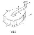
- FIG. 1is a perspective view of a piezoelectric generator according to the invention
- FIG. 2is an exploded view of the generator
- FIG. 3is an exploded view of a crank handle of the generator
- FIGS. 4-4Bare perspective, side and bottom views, respectively, of a wave plate of the generator
- FIG. 5is a perspective view of a blade assembly of the generator
- FIG. 6is a top view of a mounting plate of the blade assembly of FIG. 5 ;
- FIG. 6Ais a cross-sectional side view of the mounting plate of FIG. 6 , taken along lines 6 A— 6 A;
- FIG. 6Bis a bottom perspective view of the mounting plate of FIG. 6 ;
- FIG. 7shows a blade of the blade assembly of FIG. 5 ;
- FIG. 7Ais an exploded view of the blade of FIG. 7 ;
- FIG. 7Bis an exploded view of a piezoelectric layer of the blade of FIG. 7 ;
- FIGS. 8 and 8Aare top and bottom perspective views, respectively, of a circuit board of the generator
- FIGS. 9 and 9Aare circuit diagrams of the generator electronics
- FIGS. 10-10Bare top and two side views, respectively, of the generator
- FIG. 11is a side view of a transducer element coupled to a sinusoidal cam
- FIGS. 12 a - 12 lshow waveforms corresponding to the response of the system of FIG. 11 ;
- FIG. 13is a side view of two transducer elements coupled to the sinusoidal cam of FIG. 11 ;
- FIGS. 14 a - 14 lshow waveforms corresponding to the response of the system of FIG. 13 ;
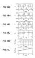
- FIGS. 15 a - 15 lshow waveforms corresponding to the response of a system with three transducers
- FIGS. 16 a - 16 lshow waveforms corresponding to the response of a system with four transducers
- FIG. 17 ais a perspective view of a piezoelectric generator according to the invention.
- FIG. 17 bis an exploded view of the generator
- FIG. 18shows a crank handle and insert of the generator with the crank handle in an open position
- FIG. 19is an exploded view of a case of the generator.
- FIG. 20 ais a perspective view of a wave plate and a blade assembly of the generator
- FIG. 20 bis an exploded view of the blade assembly
- FIGS. 20 c - 20 fshow various components of the blade assembly
- FIG. 21is a perspective view of a case cover
- FIGS. 22 a and 22 bare perspective views of an alternative embodiment of a generator mechanism, a top plate of the mechanism shown removed for illustrative purposes in FIG. 22 b;
- FIGS. 23 a and 23 bare perspective views of another alternative embodiment of a generator mechanism, with only one transducer element being shown in FIG. 23 a for clarity;
- FIG. 24is a perspective view of an alternative embodiment of a piezoelectric generator according to the invention.
- FIG. 25is an exploded view of the piezoelectric generator of FIG. 24 ;
- FIG. 26is a further exploded view of the piezoelectric generator of FIG. 24 ;
- FIG. 27shows a blade assembly of the piezoelectric generator of FIG. 24 ;
- FIG. 28shows a piezoelectric bimorph of the blade assembly of FIG. 27 ;
- FIG. 29shows a representation of an active element in sequential stages of longitudinal and rotational deflection.
- a handheld piezoelectric generator 10employing piezoelectric elements for harvesting electric power from a mechanical input includes a housing 12 and a crank handle 14 .
- Handle 14is coupled to housing 12 for rotation relative thereto, and includes an arm 16 and a knob 18 .
- housing 12includes a case 20 and a case cover 22 attached to case 20 with screws 24 .
- Located within housing 12are a wave plate 30 , a piezoelectric blade assembly 32 , and a circuit board 34 .
- circuit board 34When assembled, circuit board 34 rests on a top surface 36 of case cover 22 and is restrained within a peripheral wall 38 of the case cover. Circuit board 34 and blade assembly 32 are separated by a spacer 54 that is glued onto bottom surface 56 of blade assembly 32 .
- Handle 14screws onto a shaft 40 that couples handle 14 and wave plate 30 such that rotating handle 14 causes wave plate 30 to rotate.
- Shaft 40includes threaded regions 42 , 44 and 46 , an enlarged, unthreaded region 58 between threaded regions 44 and 46 , and an unthreaded region 60 between threaded regions 42 and 44 .
- Threaded region 44is received within a threaded hole 50 in wave plate 30 , and threaded region 46 passes through an unthreaded hole 53 in case 20 and is received within a threaded hole 52 in handle arm 16 .
- Region 58spans across hole 53 in case 20 .
- Blade assembly 32includes a post 61 having an inner wall 62 defining a through bore 63 .
- region 60 of shaft 40is located within through bore 63 with ball bearings 64 , 65 between shaft 40 and inner wall 62 of post 61 .
- Ball bearings 64 , 65are separated by a spacer 66 .
- Threaded region 42 of shaft 40is received within a nut 48 . which holds shaft 40 in place.
- Between nut 48 and bearing 64is a shim 67
- bearing 65 and a lower surface 67 of wave plate 30are shims 68 .
- Case cover 22defines four through holes 69 a through which screws 24 pass
- case 20defines four threaded holes 69 b which receive screws 24 .
- handle arm 16includes a mount 70 over which an elbow member 71 is placed.
- Mount 70defines a threaded hole 72 which receives a screw 73 for securing elbow member 71 to mount 70 while permitting elbow member 71 to rotate relative to mount 70 .
- Mount 70has a bulge 74 and elbow member 71 defines a through hole 75 with a ledge 76 that engages bulge 74 when handle 14 is turned clockwise. If one tries to turn handle 14 counterclockwise, elbow member 71 merely rotates about mount 70 . This limits possible damage to blade assembly 32 , which may occur if wave plate 30 is turned counterclockwise.
- Elbow member 71includes a cylindrical extension 77 defining a threaded hole 78 . Knob 18 is received over extension 77 and secured to extension 77 with a screw 80 .
- wave plate 30includes a base section 86 and a peripheral wall 88 .
- Peripheral wall 88has a face 90 formed with a sinusoidal wave pattern 92 .
- Wave pattern 92includes thirty-three waves peak-to-peak. The waves are offset relative to the wave plate diameter, i.e., the wave axis, X, is at an angle, ⁇ , of about 40° relative to plate diameter, D, such that the waves mate with blade tips 126 .
- Wave plate 30is formed of aluminum with a Teflon impregnated hardcoat finish for low friction, thus increasing efficiency.
- blade assembly 32includes a mounting plate 100 and twenty-four equally, circumferentially spaced blades 102 attached to plate 100 and bendable relative to plate 100 .
- mounting plate 100includes twenty-four angled slots 104 , each for receiving a blade 102 .
- Lower surface 56 of mounting plate 100defines circumferential cut-outs 106 , 108 to reduce the weight of the mounting plate.
- the cut-outsform circumferential lips 110 , 112 and 114 .
- Inner wall 62 of post 61has a middle region 66 a of a first diameter for receiving spacer 66 , an outer regions 64 a , 65 a of larger diameter for receiving bearings 64 , 65 , respectively.
- the thirty-three sine waves in pattern 92 and the twenty-four blades 102define eight different phases of contact between pattern 92 and blades 102 . At all times, three equally spaced blades 102 , 120° apart, are at the same phase and thus contacting pattern 92 at the same point in an individual sine wave. This stabilizes wave plate 30 and blade assembly 32 by providing three points of even contact between the wave plate and blade assembly, and spaces the timing of maximum deflection of the blades. Having multiple phases has the effect of providing low ripple torque.
- each blade 102includes a steel shim 120 sandwiched between two piezoelectric layers 122 a , 122 b .
- Each piezoelectric layer 122 a , 122 bincludes a wafer or active fiber preform 123 between two uniform or interdigitated electrodes 125 .
- Each electrode 125includes a circuit connector 127 with electric leads 128 for making correction to a circuit, described below.
- Shim 120includes a bent extension member 124 with an outer surface 126 that rides along face 90 of wave plate 30 .
- Each blade 120has a thickness of about 0.04 inches.
- Blades 102are shaped and orientated on mounting plate 100 to pack tightly, and are triangular in shape to spread the stress evenly over substantially all of the piezoelectric material.
- the blade thickness and shapeare designed to maximize electromechanical coupling between the tip deflection and electric output.
- Shim 120includes tabs 140 which aid in positioning shims 120 on mounting plate 100 .
- circuit board 34has a top surface 150 , a bottom surface 152 , and 24 holes 154 through which circuit connectors 127 extend.
- a switching regulator 156On top surface 150 are located a switching regulator 156 , a transformer 158 , and capacitors 160 a , 160 b .
- capacitors 160 a , 160 bOn bottom surface 152 are rectifier bridges 162 a-d and capacitors and resistors 164 .
- Electric leads 128 of circuit connectors 127are connected to rectifier bridges 162 a-d with each of the three blades 102 undergoing deformation in phase jointly connected to a side of one of the rectifier bridges.
- Rectifier bridges 162 a-dare connected to capacitors 160 a , 160 b .
- Capacitors and resistors 164act as filtering components for switching regulator 156 .
- Switching regulator 156maintains the voltage across capacitors 160 a , 160 b at voltage which maximizes power transfer from piezoelectrics 123 .
- the peak-to-peak open circuit voltage of piezoelectrics 123is 800 volts and capacitors 160 a , 160 b are maintained at about 200 volts.
- the voltage level at which capacitors 160 a , 160 b are maintainedis controlled by zener diode 170 and resistors 172 , 174 .
- zener diode 170when the voltage across capacitors 160 a , 160 b reaches about 200 volts, a transistor 176 is turned on, enabling switching regulator 156 .
- switching regulator 156switches on and off, current flows from capacitors 160 a , 160 b through the primary of transformer 158 .
- the secondary of transformer 158outputs power at a low voltage (about 5 volts) for powering an external device.
- the circuithas a power conversion efficiency as high as about 80%.
- generator 10is sized to fit in a users palm having an overall length, L 1 , of about 4.5 inches, and overall width, W 1 , of about 3 inches, and an overall height, H 1 , of about 2 inches.
- Housing 12has an overall length, L 2 , of about 4.2 inches, and an overall height, H 2 , of about 1 inch.
- Generator 10can be an independent device with a power cord that plugs into a device being powered, or generator 10 can be an integral component of the device being powered.
- generator 10can be actuated by a squeezing action or by pulling a string.
- generator 10can include a jagged toothed plate which cause free vibration of blades 102 .
- Therecan be a gear, cam, chain or belt drive between handle 14 and wave plate 30 such that wave plate 30 rotates, for example, four times for every turn of handle 14 .
- the piezoelectric elementcan have any number of geometries, for example, a single wafer, a stack, or a bimorph.
- the devicecan incorporate mechanical levering or amplification systems.
- This fundamental limit on conversion efficiencycan be circumventing by reusing the mechanical energy (E mech ) that would otherwise be wasted, for example, by transferring the energy to other transducer elements in the device.
- E mechmechanical energy
- FIG. 11we first consider a system 300 including one transducer element 301 , conceptually represented as a spring, coupled to a cam 302 having a sinusoidal groove 303 . As cam 302 is pushed in the x direction, transducer element 301 moves up and down in the y direction within groove 303 . A bearing 304 can be used such that the friction between cam 302 and transducer element 301 is negligible.
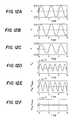
- FIGS. 12 a - 12 lshow waveforms corresponding to the response of such a system.
- FIGS. 12 a - 12 fshow the response during open circuit operation.
- FIG. 12 ashows the deformation of transducer element 301 .
- FIG. 12 bshows the voltage generated by transducer element 301 .
- FIG. 12 cshows the force applied to transducer element 301 by cam 302 .
- FIG. 12 dshows the force that is applied to cam 302 by the mechanical input.
- FIG. 12 eshows the power input to the system by the mechanical input (solid line) as well as the electrical power extracted (dashed line). In the open circuit case, no electrical energy is extracted from transducer element 301 .
- FIG. 12 fshows the integral of the power in and power extracted.
- FIGS. 12 g - 12 lshow corresponding waveforms obtained when transducer element 301 is connected to a harvesting circuit such as described in U.S. Ser. No. 09/584,881, entitled Electrical Power Extraction from Mechanical Disturbances, filed Jun. 1, 2000, hereby incorporated by reference herein in its entirety.
- a switch(not shown) is turned on, and the electrical energy is extracted through an inductor (not shown). It can be seen from FIG. 12 k that a significant fraction of the mechanical power that flows into the device flows back out during each cycle. The power flowing out would generally be wasted and is the main reason for the low conversion efficiency.
- transducer element 301is in an unstressed condition and transducer element 305 is stressed.
- cam 302moves in the direction of arrow, X, the stress on transducer element 305 decreases, and the stress on transducer element 301 increases.
- energy being returned by transducer element 305is transferred to transducer element 301 through cam 302 .
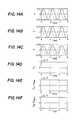
- FIGS. 14 a - 14 fshow the response during open circuit operation.
- the key featureis that because the two transducer elements 301 , 305 are 90 degrees out of phase, the net force on the cam is zero. Thus, during open circuit operation (and in the absence of frictional losses), no energy is required to move the cam. As the cam moves, the energy required to move one transducer element is balanced by the mechanical energy being returned by the other transducer element.
- FIGS. 14 g - 14 lshow the corresponding waveforms when the system is connected to a harvesting circuit.
- the net force on the camis not zero ( FIG. 14 j ).
- FIG. 14 kno mechanical power flows out of the device.
- the mechanical energy input in the devicebalances the electrical energy harvested.
- the coupling coefficient of an energy harvesting system using this configurationcan be as high as 1. That is 100% of the mechanical energy supplied to the device can be extracted as electrical energy.
- the conversion efficiencywill be lower that 100%.
- the efficiencywill be higher than the efficiency that would be achieved without reusing the mechanical elastic energy.
- FIGS. 15 and 16show similar waveforms for a system using three transducer elements and a system using four transducer elements, respectively.
- Three transducers at 60 and 120 degrees of phasewill produce the desired cancellation.
- Four transducers at 90 degrees of phase between the transducer elementswill produce the desired effect.
- a handheld piezoelectric generator 310which functions in the above described quasi-static mode in which non-converted mechanical energy is redistributed within the system, includes a housing 312 and a crank handle 314 .
- Handle 314is coupled to housing 312 for rotation relative thereto, and includes an arm 316 and a finger grasp 318 .
- housing 312includes a case 320 and a case cover 322 attached to case 320 with screws, not shown.
- Located within housing 312are a wave plate 330 , a blade assembly 332 , and a circuit board 334 .
- handle arm 316is mounted to an insert 370 by a pin 316 a such that handle arm 316 can be moved from the closed position of FIG. 17 a to the open, actuation position of FIG. 18 .
- Finger grasp 318is coupled to handle arm 316 by a member 371 that is mounted to handle arm 316 by a pin 371 a such that finger grasp 318 can be moved from the closed position of FIG. 17 a to the open, actuation position of FIG. 18 .
- Finger grasp 318is mounted to member 371 to rotate along arrow 318 a .
- Insert 370is received within an opening 370 a in case 320 .
- insert 370has an inner side 340 defining three cut-out regions 342 .
- a gear 344mounted within each cut-out region 342 .
- a washer 346for holding the gears in place.
- case 320includes a stationary internal gear ring 348 extending from an inner surface 350 of case 320 .
- Gears 344extend through opening 370 a in case 320 and mate with gear ring 348 . In operation, rotation of handle 314 , for example, in the clockwise direction, causes rotation of insert 370 and gears 344 in the clockwise direction.
- gears 344With gear ring 348 causes gears 344 to rotate about their own axes in the counterclockwise direction at four times the speed of the clockwise rotation.
- a bearing 372Positioned around gear ring 348 and against inner surface 350 is a bearing 372 .
- wave plate 330includes a gear 352 that is received between gears 344 . Clockwise rotation of gears 344 causes counterclockwise rotation of gear 352 and wave plate 330 .
- the relative number of gear teeth in gear ring 348 , gears 344 , and gear 352is such that, for example, for each rotation of handle 314 , gear 352 rotates four times.
- Wave plate 330includes a base section 386 and gear 352 is mounted to base section 386 .
- Base section 386has a ledge 387 against which bearing 372 rests, and extending upward from a bottom surface 385 of wave plate 330 is a peripheral wall 388 .
- Peripheral wall 388has an outer face 390 with a cut-out 391 bounded by upper and lower surfaces 391 a , 391 b each formed in a matching sinusoidal wave pattern 392 .
- Wave pattern 392includes 10 waves peak-to-peak.
- blade assembly 332includes a support 400 ( FIG. 20 c ) and eight layers 402 of piezoelectric material mounted to support 400 and bendable relative to support 400 in the directions of arrow 404 .
- Layers 402are separated by shims 408 ( FIG. 20 e ), and top layer 402 a is separated from a bottom surface 385 ( FIG. 20 a ) of wave plate 330 by a top shim 408 a .
- Extending from support 400are six pins 410 that extend through holes 412 and 414 defined in layers 402 and shims 408 , respectively.
- a shaft 415extends through holes 416 , 417 and 418 defined in support 400 , layers 402 , and shims 408 , respectively, and through a hole 410 defined in wave plate 330 .
- a bearing(not shown) is located between shaft 415 and wave plate 330 .
- Blade assembly 332is coupled to wave plate 330 by six coupling mounts 430 ( FIG. 20 f ). Each coupling mount 430 defines eight slots 432 , each slot 432 for receiving one layer 402 . Each coupling mount 430 has a bearing 434 mounted thereto ( FIG. 20 a ) that rides within cut-out 391 in wave plate 330 . Bearings 434 provide a low friction coupling between wave plate 330 and blade assembly 332 .
- Coupling mounts 430define three pairs of coupling mounts 430 a , 430 b , 430 c .
- the spacing of the six coupling mountsstabilizes wave plate 330 and blade assembly 332 , and spaces the timing of maximum deflection of the blades.
- the two coupling mounts 430 within each pairare in phase and the different pairs are 120 degrees out of phase.
- the motion of bearings 434causes each layer 402 to flex upward and downward, straining the piezoelectric elements.
- the ten sine waves in pattern 392 and the six contact points between blade assembly 332 and wave plate 330define three different phases of contact between pattern 292 and blade assembly 332 , each phase corresponding to one of the pairs of coupling mounts 430 a , 430 b , 430 c .
- Bounding bearings 434 between upper and lower sinusoidal surfaces 391 a , 391 bprovides for maximum deflection of layers 402 in both the upward and downward directions.
- circuit board 334has a support 350 with three arms 352 .
- Case cover 322has three sets of rails 354 defining slots 356 for receiving arms 352 .
- circuitry 358such as described above.
- Generator 310is sized to fit in a users palm having an overall length of about 4.5 inches, and overall width of about 3 inches, and an overall height of about 1.2 inches.
- Generator 310can be an independent device with a power cord that plugs into a device being powered, or generator 310 can be an integral component of the device being powered.
- the generatorcan be actuated by a squeezing action or by pulling a string.
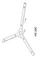
- an alternative embodiment of a piezoelectric generator 501which functions in the above described quasi-static mode in which non-converted mechanical energy is redistributed within the system, can be embedded within the heel of a boot.
- the device 501includes a top plate 502 and bottom plate 503 that are connected to one another through a pivot 504 . Stepping on the heel of the boot causes top plate 501 to be pressed towards bottom plate 503 .
- top plate 502is connected to a helical screw 505 and compression springs 514 .
- screw 505forces the helical nut to rotate.
- the helical nut 506is mated to a one-way clutch bearing 507 , which is in turn mated to an insert 508 , thus causing the insert to rotate along with the helical nut.
- Insert 508has three holes 508 a that receive pins 509 for holding gears 510 .
- a mounting plate 511includes a stationary internal gear ring 512 which mates with gears 510 .
- top plate 502In operation, downward motion of top plate 502 causes counter-clockwise rotation of helical nut 506 , insert 508 and gears 510 .
- the mating of gears 510 with the internal gear 512causes gears 510 to rotate about their own axes in clockwise rotation at, for example, 2.3 times the speed of the counter-clockwise rotation.
- a wave plate 513includes a gear 513 a fixed to the bottom side of the wave plate. Gear 513 a is received between gears 510 such that counter-clockwise rotation of gears 510 causes clockwise rotation of wave plate 513 .
- the relative number of gear teeth in internal gear 512 , gears 510 , and wave plate gear 513 ais such that, for example, for each rotation of helical nut 506 , the wave plate rotates 3.5 times.
- Wave plate 513includes a cut-out 514 having a nearly sinusoidal wave pattern. The wave pattern includes eleven waves peak-to-peak.
- the compression springs 514causes the top plate and bottom plate to move apart again.
- the one-way clutch bearing 507allows the helical nut 506 to rotate freely (without causing rotation of the gears and wave plate).
- blade assemblies 515include a support 516 , and eight layers of piezoelectric bimorphs 517 .
- the layered construction of each piezoelectric bimorphincludes a shim 518 and a piezoelectric element 519 on each side of the shim. The bimorphs are clamped at the base through holes 520 .
- Each blade assembly 515is coupled to the wave plate through a bearing 521 located in cut-out 514 . Bearings 521 provide a low friction coupling between wave plate 513 and the blade assembly 515 .
- the bearings 521move from side to side in the sinusoidal wave pattern 514 .
- the motion of the bearingscauses each blade assembly to flex side to side.
- the four bearings 521 and the eleven sine waves in pattern 514define four phases between pattern 514 and the blade assemblies 515 .
- the four blade assembliesmove with 90 degrees of phase between them, to produce the desired redistribution of mechanical energy in the system.
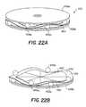
- FIGS. 22 a and 22 bshow an alternative embodiment of the invention.
- a generator mechanism 450includes a segmented piezoelectric disk 452 bonded to a circular plate 454 .
- Plate 454is sandwiched between upper and lower plates 458 a , 458 b .
- Located between plate 454 and upper plate 458 aare a series of ball bearings or rollers 456 a
- an additional series of ball bearings or rollers 456 bLocated between plate 454 and upper plate 458 a are a series of ball bearings or rollers 456 a
- Plate 454is deformed under pressure from ball bearings 456 a , 456 b acting on the top and bottom surfaces 459 , 460 of plate 454 .
- Ball bearings 456 a , 456 bare spaced to produce a wave along the circumference of the circular plate 454 .
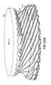
- upper and lower plates 458 a , 458 bare stationary and plate 454 is rotated.
- Rotation of plate 454causes ball bearings 456 a , 456 b to rotate at half the speed of plate 454 .
- the wavetravels around the circumference of the plate.
- each segment of piezoelectric disk 452experiences cyclic loads, resulting in a voltage generated by the piezoelectric.
- This signalis rectified to extract electrical energy from the system. Since the plate deformation corresponds to a wave with constant amplitude, the total mechanical energy in the system remains substantially unchanged. Instead, the locations with maximum mechanical energy rotate around the disk. This system is similar to the system of FIG.
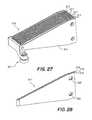
- a generatorin another embodiment, the energy stored in the form of mechanical energy in the transducer element is harvested by taking advantage of free vibrations of the element.
- a generatorincludes cantilevered bimorph transducer elements 472 mounted to a stationary member 473 , and a rotatable disk 474 for inducing a deflection at the tip 476 of each transducer element 472 .
- Disk 474includes teeth 478 for deflecting transducer elements 472 .
- a transducer element 472clears the tip 480 of a tooth 478 , transducer element 472 is free to vibrate.
- an electronic circuitsuch as described in U.S. Ser. No. 09/584,881, supra, coupled to the transducer element extracts electric power.
- transducer element 472During the initial swing, as transducer element 472 reaches the peak of its deformation, a fraction of the energy is stored as electrical energy and the remainder is stored as mechanical energy. The electrical energy is harvested by the electric circuit connected to the transducer element. As transducer element 472 swings back towards it equilibrium position, the mechanical energy is converted to kinetic energy. As transducer element 472 continues to swing to the peak deformation in the opposite side, again a fraction of the energy is stored in electrical energy and the remainder is stored as mechanical energy.
- a controlled interface generatorincludes a rotary or translating body 610 , which is acted on by an external force or torque, F, and exhibits rotation or translation resulting from this external force or torque.
- One or more active elements 612intermittently make contact at single or multiple contact ports with body 610 . Alternately, the active element can be acted on directly by the external force or torque and exhibit rotation or translation and the body can be fixed.
- the active element 612has two primary functions or behaviors.
- element 612is configured to make controllable intermittent contact with body 610 at one or more contact points. This controllable motion into or out of contact with body 610 is the contact component of motion (COCM).
- COCMcontact component of motion
- the contact component of motion (COCM)enables active element 612 to make contact with body 610 , and is typically loosely aligned with normal to body 610 at the contact point(s).
- the second, called the Carry component of motion (CACM)enables active element 612 to translate with a motion parallel to the motion of body 610 at the contact point(s) due to the motion of body 610 .
- active element 612has two components of motion at the contact point(s).
- the contact component of motion (COCM) of the active elementcan be controlled by a contact control mechanism, for example, electromagnetics, pneumatics, hydraulics, thermal actuation, or active materials such as magnetostrictive, piezoelectric, electrostrictive, etc.
- the contact control mechanismallows controllable intermittent contact between active element 612 and body 610 . This can be achieved through quasi-static motion or dynamic motion of the contact point.
- a piezoelectric elementcan be coupled to a vibration mode of the active element, which has motion at the contact point(s) in the COCM direction. If the piezoelectric element is excited at a frequency at or near the natural resonance frequency of that mode, the resonance of the active element will cause relatively large amplitude motion in the COCM direction.
- the vibrating active elementIf the vibrating active element is positioned in proximity to the body 610 , intermittent contact will occur during some portion of the vibration cycle.
- the vibrating active elementcan also be pushed against the body by a soft support and intermittent contact will also occur since the soft support cannot maintain contact between the active element and the body at the contact points during all portions of the vibration cycle.
- the contact point on the active elementcan be moved into contact with the body through control signals, (voltage drive or a piezoelectric stack, or bimorph) at frequencies below the first mode of the active element which has motion components in the COCM direction of the contract points.
- a piezoelectric or piezomagnetic element(magnetostrictive, electrostrictive magnetic shape memory alloy etc) is coupled to (and configures in) the active element such that CACM direction forces and motion are coupled to the voltage and current or charge (collectively the electrical states of the system) at a set of generating element electrodes or electrical terminals.
- These electrodesare in turn connected to electronics for extraction of electrical power from the mechanical disturbances represented by the intermittent forcing of the active element by the above mentioned contact forces.
- the electronicscan be a passive diode arrangement (passive energy harvesting) such as a full bridge or more complex electronics involving switches under active control (active energy harvesting), as discussed in U.S. Ser. No. 09/584,881, supra.
- the controlled intermittent contact (potentially periodic) to body 610produces an intermittent (periodic) deformation of active element 612 and resulting oscillation of the voltage or current signal present at the generating element electrodes. This allows for electrical energy extraction from the active or passive extraction circuitry.
- the CACM direction motion of the active element at the contact pointcan be dynamic or quasi-static depending on the implementation.
- a dynamic implementationconsider a coupling between the generating element and a mode of the active element that has large motion at the contact points in the CACM direction. Then periodic mechanical excitation of this mode by the controlled periodic (intermittent) contact forces in the CACM direction can result in forced excitation of the dynamic (resonant) modal oscillation of the active element and through its coupling, the generating element. Oscillatory forcing of the generating element and connected extraction electronics then enable electrical power extraction.
- CACMcoupled to the generator element
- COCMcoupled to and controlled by the contact control means
- a quasi-static version of the systemcan use, for example, a burleigh inchworm motor with an expander as the generator element.
Landscapes
- General Electrical Machinery Utilizing Piezoelectricity, Electrostriction Or Magnetostriction (AREA)
Abstract
Description
ky−Nv=F
Ny+Cv=Q
where y is the deformation of the transducer element, F is the force applied, v is the voltage across the electrodes of the transducer, Q is the charge produced, k is the equivalent stiffness of the transducer taking into account any mechanical amplification or geometric factors, N is the piezoelectric constant scaled by appropriate geometric factors, and C is the capacitance of the device.
v=−Ny/C
Total Work done on the system is:
Total mechanical energy stored in the system is:
Total electrical energy stored in the system is:
The square root of the ratio between the stored electrical energy, and the total work done on the system is known as the coupling coefficient (K) of the transducer element, and is a function of the material properties and geometry of the element:
Eelecrepresents the maximum amount of electric energy which can be harvested from the system in each cycle. The remainder of the work that was done on the system (Emech) cannot be harvested electrically as it is stored in the elastic deformation of the transducer element. As the transducer is returned to its undeformed position, the mechanical energy is returned to the mechanical input. In many cases, however, the mechanical input cannot efficiently absorb the returned energy. Thus this energy is wasted. Based on this analysis, the maximum conversion efficiency of such a device is generally limited by the coupling coefficient squared. Depending on the type of transducer material and the geometry, this efficiency can range between 0.1-0.4.
F is the force on
Claims (46)
Priority Applications (1)
| Application Number | Priority Date | Filing Date | Title |
|---|---|---|---|
| US10/724,705US6909224B2 (en) | 2000-10-20 | 2003-12-02 | Piezoelectric generator |
Applications Claiming Priority (4)
| Application Number | Priority Date | Filing Date | Title |
|---|---|---|---|
| US24190500P | 2000-10-20 | 2000-10-20 | |
| US25169600P | 2000-12-06 | 2000-12-06 | |
| US09/986,205US6655035B2 (en) | 2000-10-20 | 2001-10-19 | Piezoelectric generator |
| US10/724,705US6909224B2 (en) | 2000-10-20 | 2003-12-02 | Piezoelectric generator |
Related Parent Applications (1)
| Application Number | Title | Priority Date | Filing Date |
|---|---|---|---|
| US09/986,205ContinuationUS6655035B2 (en) | 2000-10-20 | 2001-10-19 | Piezoelectric generator |
Publications (2)
| Publication Number | Publication Date |
|---|---|
| US20040108724A1 US20040108724A1 (en) | 2004-06-10 |
| US6909224B2true US6909224B2 (en) | 2005-06-21 |
Family
ID=29272863
Family Applications (2)
| Application Number | Title | Priority Date | Filing Date |
|---|---|---|---|
| US09/986,205Expired - LifetimeUS6655035B2 (en) | 2000-10-20 | 2001-10-19 | Piezoelectric generator |
| US10/724,705Expired - LifetimeUS6909224B2 (en) | 2000-10-20 | 2003-12-02 | Piezoelectric generator |
Family Applications Before (1)
| Application Number | Title | Priority Date | Filing Date |
|---|---|---|---|
| US09/986,205Expired - LifetimeUS6655035B2 (en) | 2000-10-20 | 2001-10-19 | Piezoelectric generator |
Country Status (4)
| Country | Link |
|---|---|
| US (2) | US6655035B2 (en) |
| EP (1) | EP1362381A1 (en) |
| AU (1) | AU2002220129A1 (en) |
| WO (1) | WO2002047181A1 (en) |
Cited By (6)
| Publication number | Priority date | Publication date | Assignee | Title |
|---|---|---|---|---|
| US20080143195A1 (en)* | 2006-10-19 | 2008-06-19 | Boise State University | Magnetomechanical transducer, and apparatus and methods for harvesting energy |
| US20100219646A1 (en)* | 2008-07-16 | 2010-09-02 | Halliburton Energy Services, Inc. | Apparatus and Method for Generating Power Downhole |
| US20110110139A1 (en)* | 2006-11-14 | 2011-05-12 | Boise State University | Multi-state memory and multi-functional devices comprising magnetoplastic or magnetoelastic materials |
| US8586194B2 (en) | 2007-08-30 | 2013-11-19 | Boise State University | Polycrystalline foams exhibiting giant magnetic-field-induced deformation and methods of making and using same |
| US9744563B2 (en) | 2010-09-27 | 2017-08-29 | Techtonic Pty Ltd | Undulatory structures |
| US10069441B2 (en) | 2015-10-21 | 2018-09-04 | Analog Devices, Inc. | Electric energy scavenger device |
Families Citing this family (49)
| Publication number | Priority date | Publication date | Assignee | Title |
|---|---|---|---|---|
| US6655035B2 (en)* | 2000-10-20 | 2003-12-02 | Continuum Photonics, Inc. | Piezoelectric generator |
| US7081693B2 (en)* | 2002-03-07 | 2006-07-25 | Microstrain, Inc. | Energy harvesting for wireless sensor operation and data transmission |
| US20050057123A1 (en)* | 2003-07-11 | 2005-03-17 | Deng Ken Kan | Piezoelectric vibration energy harvesting device and method |
| US20050134149A1 (en)* | 2003-07-11 | 2005-06-23 | Deng Ken K. | Piezoelectric vibration energy harvesting device |
| US7557433B2 (en) | 2004-10-25 | 2009-07-07 | Mccain Joseph H | Microelectronic device with integrated energy source |
| US7794499B2 (en) | 2004-06-08 | 2010-09-14 | Theken Disc, L.L.C. | Prosthetic intervertebral spinal disc with integral microprocessor |
| US7239066B2 (en)* | 2004-06-17 | 2007-07-03 | Par Technologies, Llc | Piezoelectric generators and methods of operating same |
| FR2873242B1 (en)* | 2004-07-13 | 2007-12-21 | Commissariat Energie Atomique | MONOLITHIC MINIATURE VOLTAGE CONVERTER WITH VERY LOW ENTRY VOLTAGE |
| US7594727B2 (en) | 2004-12-03 | 2009-09-29 | Searete Llc | Vision modification with reflected image |
| US7334892B2 (en) | 2004-12-03 | 2008-02-26 | Searete Llc | Method and system for vision enhancement |
| US7486988B2 (en) | 2004-12-03 | 2009-02-03 | Searete Llc | Method and system for adaptive vision modification |
| US7470027B2 (en) | 2004-12-03 | 2008-12-30 | Searete Llc | Temporal vision modification |
| US7931373B2 (en) | 2004-12-03 | 2011-04-26 | The Invention Science Fund I, Llc | Vision modification with reflected image |
| US7334894B2 (en) | 2004-12-03 | 2008-02-26 | Searete, Llc | Temporal vision modification |
| US7344244B2 (en) | 2004-12-03 | 2008-03-18 | Searete, Llc | Adjustable lens system with neural-based control |
| US8104892B2 (en) | 2004-12-03 | 2012-01-31 | The Invention Science Fund I, Llc | Vision modification with reflected image |
| US7390088B2 (en) | 2004-12-03 | 2008-06-24 | Searete Llc | Adjustable lens system with neural-based control |
| US9155483B2 (en) | 2004-12-03 | 2015-10-13 | The Invention Science Fund I, Llc | Vision modification with reflected image |
| US7350919B2 (en) | 2004-12-03 | 2008-04-01 | Searete Llc | Vision modification with reflected image |
| US8244342B2 (en) | 2004-12-03 | 2012-08-14 | The Invention Science Fund I, Llc | Method and system for adaptive vision modification |
| US7656569B2 (en) | 2004-12-03 | 2010-02-02 | Searete Llc | Vision modification with reflected image |
| US9067047B2 (en) | 2005-11-09 | 2015-06-30 | The Invention Science Fund I, Llc | Injectable controlled release fluid delivery system |
| US7348683B2 (en)* | 2005-11-17 | 2008-03-25 | General Electric Company | Rotor for a wind energy turbine |
| WO2007061610A1 (en)* | 2005-11-18 | 2007-05-31 | Par Technologies, Llc | Human powered piezoelectric power generating device |
| US7692365B2 (en)* | 2005-11-23 | 2010-04-06 | Microstrain, Inc. | Slotted beam piezoelectric composite |
| US20080140057A1 (en) | 2006-03-09 | 2008-06-12 | Searete Llc, A Limited Liability Corporation Of State Of The Delaware | Injectable controlled release fluid delivery system |
| DE102006025963A1 (en)* | 2006-06-02 | 2007-12-06 | Epcos Ag | Piezoelectric generator |
| US20080084138A1 (en)* | 2006-10-10 | 2008-04-10 | Micallef Joseph A | Apparatus For Piezoelectric Generation of Power To Propel An Automobile and Method of Making |
| US7459837B2 (en)* | 2006-12-20 | 2008-12-02 | The Boeing Company | Broadband energy harvester apparatus and method |
| US7605482B2 (en)* | 2007-01-08 | 2009-10-20 | Veryst Engineering Llc | Method and apparatus for energy harvesting using energy storage and release |
| CA2681173C (en)* | 2007-03-21 | 2013-11-12 | The University Of Vermont And State Agricultural College | Piezoelectric vibrational energy harvesting systems incorporating parametric bending mode energy harvesting |
| DE112008001076T5 (en) | 2007-05-25 | 2010-04-15 | Searete LLC, Bellevue | System for a controlled application of an injectable fluid |
| US8217523B2 (en) | 2007-12-07 | 2012-07-10 | Veryst Engineering Llc | Apparatus for in vivo energy harvesting |
| TWI394352B (en)* | 2009-07-16 | 2013-04-21 | Silicon Touch Tech Inc | Power generating device |
| TWI420797B (en)* | 2010-04-12 | 2013-12-21 | Univ Nat Sun Yat Sen | Piezoelectric power apparatus |
| US9259580B2 (en) | 2010-08-09 | 2016-02-16 | Pi-Harvest Holding Ag | Medical system, piezoelectric kit, related methods and medical procedures |
| WO2012122178A2 (en)* | 2011-03-10 | 2012-09-13 | Halliburton Energy Services, Inc. | Magnetostrictive power supply for bottom hole assembly with rotation-resistant housing |
| WO2012164545A1 (en)* | 2011-06-03 | 2012-12-06 | Ecole Polytechnique Federale De Lausanne (Epfl) | Energy scavenging from a rotating gear using an impact type piezoelectric mems scavenger |
| KR101746070B1 (en)* | 2011-09-16 | 2017-06-12 | 가부시키가이샤 하모닉 드라이브 시스템즈 | Vibration power-generating strain wave gearing |
| US20130088020A1 (en)* | 2011-10-11 | 2013-04-11 | Lalitha Vellore Sripathi Rao | Method, System, Apparatus to generate electricity from objects under motion |
| US9913321B2 (en)* | 2013-01-25 | 2018-03-06 | Energyield, Llc | Energy harvesting container |
| US9431928B2 (en)* | 2013-11-06 | 2016-08-30 | Oscilla Power Inc. | Power production in a completed well using magnetostrictive materials |
| US9377223B1 (en)* | 2013-11-12 | 2016-06-28 | George L Williamson | Thermos with peltier |
| FR3025371B1 (en)* | 2014-09-02 | 2018-05-18 | Franck Proux | ELECTRICITY GENERATION SYSTEM WITH DIRECT PIEZOELECTRIC EFFECT AND HOMELOMOTOR COMPRISING SAID SYSTEM |
| FR3029241B1 (en)* | 2014-12-01 | 2019-05-03 | Gilles Grosso | APPARATUS FOR CONVERTING HOT ENERGY IN ELECTRICAL ENERGY |
| US9911290B1 (en) | 2015-07-25 | 2018-03-06 | Gary M. Zalewski | Wireless coded communication (WCC) devices for tracking retail interactions with goods and association to user accounts |
| US10355730B1 (en) | 2015-07-25 | 2019-07-16 | Gary M. Zalewski | Wireless coded communication (WCC) devices with power harvesting power sources for processing internet purchase transactions |
| JP6670611B2 (en)* | 2016-01-13 | 2020-03-25 | 正毅 千葉 | Dielectric elastomer motor |
| CN113241968A (en)* | 2021-05-19 | 2021-08-10 | 杭州电子科技大学 | Vibration energy collecting device |
Citations (64)
| Publication number | Priority date | Publication date | Assignee | Title |
|---|---|---|---|---|
| US3101420A (en)* | 1961-11-06 | 1963-08-20 | Clevite Corp | Distorted bearing piezoelectric voltage source |
| US3211069A (en) | 1963-05-31 | 1965-10-12 | Westinghouse Electric Corp | Flash gun for photoflash lamps and piezoelectric ignition energy generating apparatus for use therein |
| US3350583A (en)* | 1963-11-13 | 1967-10-31 | Edward L Schiavone | Electric power supply |
| US3396311A (en) | 1964-09-21 | 1968-08-06 | Maltner Heinrich Gmbh | Piezo-electric spark igniter |
| US3539841A (en)* | 1968-02-21 | 1970-11-10 | Motorola Inc | Piezoelectric voltage generator |
| US3558903A (en) | 1966-06-25 | 1971-01-26 | Rion Co | Mechanically activated piezoelectric voltage source |
| US3666976A (en) | 1965-11-10 | 1972-05-30 | Robert D Gourlay | Fluid operated electric generator utilizing a piezoelectric device |
| US3782258A (en) | 1971-12-03 | 1974-01-01 | Philips Corp | Ignition arrangement for a discharge tube |
| US3819963A (en) | 1972-02-04 | 1974-06-25 | Matsushita Electric Industrial Co Ltd | High voltage generating piezoelectric igniter |
| US4091302A (en) | 1976-04-16 | 1978-05-23 | Shiro Yamashita | Portable piezoelectric electric generating device |
| US4156825A (en) | 1977-05-06 | 1979-05-29 | Matsushita Electric Industrial Company, Limited | Piezoelectric high voltage generating device |
| US4181492A (en) | 1977-10-11 | 1980-01-01 | Striker, Inc. | Torch igniter |
| US4325356A (en) | 1979-04-09 | 1982-04-20 | Felix Taschler | Igniter for portable gas appliances |
| GB2088645A (en)* | 1980-11-28 | 1982-06-09 | Rockwell International Corp | High speed, high response drive |
| US4387318A (en)* | 1981-06-04 | 1983-06-07 | Piezo Electric Products, Inc. | Piezoelectric fluid-electric generator |
| US4417170A (en) | 1981-11-23 | 1983-11-22 | Imperial Clevite Inc. | Flexible circuit interconnect for piezoelectric element |
| US4442372A (en) | 1982-11-22 | 1984-04-10 | Walton Energy Systems Co. | Piezo electric apparatus for generating electricity |
| US4459539A (en) | 1982-07-12 | 1984-07-10 | Hewlett-Packard Company | Charge transfer constant volt-second regulator |
| US4467236A (en) | 1981-01-05 | 1984-08-21 | Piezo Electric Products, Inc. | Piezoelectric acousto-electric generator |
| US4504761A (en) | 1981-12-28 | 1985-03-12 | Triplett Charles G | Vehicular mounted piezoelectric generator |
| US4510935A (en) | 1981-10-28 | 1985-04-16 | Cardiac Recorders Limited | Cardiac defibrillator |
| US4523261A (en) | 1982-08-05 | 1985-06-11 | West Philip G | Light source, manually operated |
| US4533849A (en)* | 1982-11-05 | 1985-08-06 | U.S. Philips Corporation | Ceramic bistable deflection element |
| US4536700A (en) | 1984-03-28 | 1985-08-20 | United Technologies Corporation | Boost feedforward pulse width modulation regulator |
| US4542969A (en) | 1982-09-30 | 1985-09-24 | Yoshiaki Omura | Portable daylight electrophotography apparatus |
| US4546421A (en) | 1984-03-28 | 1985-10-08 | United Technologies Corporation | Flyback feedforward pulse width modulation regulator |
| US4595856A (en) | 1985-08-16 | 1986-06-17 | United Technologies Corporation | Piezoelectric fluidic power supply |
| US4629970A (en) | 1985-01-30 | 1986-12-16 | Telefonaktiebolaget L.M. Ericsson | Switching convertor for generating a constant magnitude dc output voltage from a dc input voltage having a varying magnitude |
| US4758754A (en) | 1986-04-01 | 1988-07-19 | C. & E. Fein Gmbh & Co. | Portable electric tool with variable torque |
| JPH01107673A (en)* | 1987-10-17 | 1989-04-25 | Asmo Co Ltd | Ultrasonic wave motor |
| US4845338A (en) | 1988-04-04 | 1989-07-04 | Nikola Lakic | Inflatable boot liner with electrical generator and heater |
| US4849668A (en) | 1987-05-19 | 1989-07-18 | Massachusetts Institute Of Technology | Embedded piezoelectric structure and control |
| US4853580A (en) | 1988-08-05 | 1989-08-01 | Tektronix, Inc. | Piezoelectric pulse generator |
| US4933230A (en) | 1986-09-17 | 1990-06-12 | American Cyanamid | Piezoelectric composites |
| US4939707A (en) | 1988-01-25 | 1990-07-03 | Seiko Epson Corporation | Electronic wristwatch with generator |
| US5034648A (en)* | 1989-10-31 | 1991-07-23 | Atochem North America, Inc. | Dual direction switch |
| US5208506A (en) | 1990-11-14 | 1993-05-04 | Nec Corporation | Laminated piezoelectric actuator |
| US5245242A (en) | 1992-04-13 | 1993-09-14 | Rockwell International Corporation | Efficiency driver system for piezoelectrics |
| US5305507A (en) | 1990-10-29 | 1994-04-26 | Trw Inc. | Method for encapsulating a ceramic device for embedding in composite structures |
| US5404067A (en) | 1990-08-10 | 1995-04-04 | Siemens Aktiengesellschaft | Bonded piezoelectric bending transducer and process for producing the same |
| US5512795A (en) | 1995-03-13 | 1996-04-30 | Ocean Power Technologies, Inc. | Piezoelectric electric energy generator |
| US5548177A (en) | 1995-02-14 | 1996-08-20 | Ocean Power Technologies, Inc | Piezoelectric generator protection |
| US5552657A (en) | 1995-02-14 | 1996-09-03 | Ocean Power Technologies, Inc. | Generation of electrical energy by weighted, resilient piezoelectric elements |
| US5552656A (en) | 1995-08-07 | 1996-09-03 | Ocean Power Technologies, Inc. | Self-powered anti-fouling device for watercraft |
| US5578889A (en) | 1995-02-14 | 1996-11-26 | Ocean Power Technologies, Inc. | Piezoelectric generation of electrical power from surface waves on bodies of water using suspended weighted members |
| WO1997004841A1 (en) | 1995-08-01 | 1997-02-13 | K-2 Corporation | Piezoelectric damper for a board such as a snow ski or snowboard |
| US5621264A (en) | 1995-08-07 | 1997-04-15 | Ocean Power Technologies, Inc. | Water craft using piezoelectric materials |
| US5656882A (en) | 1994-01-27 | 1997-08-12 | Active Control Experts, Inc. | Packaged strain actuator |
| CA2257935A1 (en) | 1996-06-17 | 1997-12-24 | Electronic Key Systems (E.K.S.) S.A.R.L. | Electronic locking device |
| US5703474A (en) | 1995-10-23 | 1997-12-30 | Ocean Power Technologies | Power transfer of piezoelectric generated energy |
| US5751091A (en) | 1995-02-01 | 1998-05-12 | Seiko Epson Corporation | Piezoelectric power generator for a portable power supply unit and portable electronic device equipped with same |
| US5783898A (en) | 1996-02-26 | 1998-07-21 | Mcdonnell Douglas Corporation | Piezoelectric shunts for simultaneous vibration reduction and damping of multiple vibration modes |
| WO1998034689A1 (en) | 1997-02-07 | 1998-08-13 | Active Control Experts, Inc. | Adaptive sports implement with selectable or tuned damping |
| US5801475A (en) | 1993-09-30 | 1998-09-01 | Mitsuteru Kimura | Piezo-electricity generation device |
| US5814921A (en) | 1995-03-13 | 1998-09-29 | Ocean Power Technologies, Inc. | Frequency multiplying piezoelectric generators |
| US5835996A (en) | 1995-12-18 | 1998-11-10 | Seiko Epscon Corporation | Power generation method and power generator using a piezoelectric element, and electronic device using the power |
| US5839508A (en) | 1995-02-09 | 1998-11-24 | Baker Hughes Incorporated | Downhole apparatus for generating electrical power in a well |
| US5857694A (en) | 1995-09-29 | 1999-01-12 | Active Control Experts, Inc. | Adaptive sports implement |
| US5900552A (en)* | 1997-03-28 | 1999-05-04 | Ohmeda Inc. | Inwardly directed wave mode ultrasonic transducer, gas analyzer, and method of use and manufacture |
| WO1999023749A1 (en) | 1997-10-30 | 1999-05-14 | Martyn Sergeevich Nunuparov | Method of power supply for electronic systems and device therefor |
| WO2000074224A1 (en) | 1999-06-01 | 2000-12-07 | Continuum Control Corporation | Electrical power extraction from mechanical disturbances |
| US6486589B1 (en)* | 2000-05-03 | 2002-11-26 | Intel Corporation | Circuit card assembly having controlled vibrational properties |
| US6545391B1 (en)* | 1999-10-22 | 2003-04-08 | The United States Of America As Represented By The Administrator Of The National Aeronautics And Space Administration | Polymer-polymer bilayer actuator |
| US6655035B2 (en)* | 2000-10-20 | 2003-12-02 | Continuum Photonics, Inc. | Piezoelectric generator |
Family Cites Families (6)
| Publication number | Priority date | Publication date | Assignee | Title |
|---|---|---|---|---|
| FR2717637B1 (en) | 1994-03-18 | 1996-06-07 | Metravib Sa | Piezoelectric device for charging an electric energy accumulator fitted to an object subjected to vibrations. |
| US5504383A (en)* | 1994-11-25 | 1996-04-02 | Xerox Corporation | High voltage power supply |
| US6194815B1 (en)* | 1996-10-25 | 2001-02-27 | Ocean Power Technology, Inc. | Piezoelectric rotary electrical energy generator |
| US5977690A (en) | 1997-08-25 | 1999-11-02 | Motorola, Inc. | Piezoelectric switch apparatus for a communication device |
| US6080817A (en)* | 1997-12-08 | 2000-06-27 | Basf Corporation | Epoxy-urethane imine and hydroxyl primer |
| US6307304B1 (en)* | 2000-04-13 | 2001-10-23 | Motorola, Inc. | Switch system |
- 2001
- 2001-10-19USUS09/986,205patent/US6655035B2/ennot_activeExpired - Lifetime
- 2001-12-06EPEP01999977Apatent/EP1362381A1/ennot_activeWithdrawn
- 2001-12-06AUAU2002220129Apatent/AU2002220129A1/ennot_activeAbandoned
- 2001-12-06WOPCT/US2001/045814patent/WO2002047181A1/ennot_activeApplication Discontinuation
- 2003
- 2003-12-02USUS10/724,705patent/US6909224B2/ennot_activeExpired - Lifetime
Patent Citations (66)
| Publication number | Priority date | Publication date | Assignee | Title |
|---|---|---|---|---|
| US3101420A (en)* | 1961-11-06 | 1963-08-20 | Clevite Corp | Distorted bearing piezoelectric voltage source |
| US3211069A (en) | 1963-05-31 | 1965-10-12 | Westinghouse Electric Corp | Flash gun for photoflash lamps and piezoelectric ignition energy generating apparatus for use therein |
| US3350583A (en)* | 1963-11-13 | 1967-10-31 | Edward L Schiavone | Electric power supply |
| US3396311A (en) | 1964-09-21 | 1968-08-06 | Maltner Heinrich Gmbh | Piezo-electric spark igniter |
| US3666976A (en) | 1965-11-10 | 1972-05-30 | Robert D Gourlay | Fluid operated electric generator utilizing a piezoelectric device |
| US3558903A (en) | 1966-06-25 | 1971-01-26 | Rion Co | Mechanically activated piezoelectric voltage source |
| US3539841A (en)* | 1968-02-21 | 1970-11-10 | Motorola Inc | Piezoelectric voltage generator |
| US3782258A (en) | 1971-12-03 | 1974-01-01 | Philips Corp | Ignition arrangement for a discharge tube |
| US3819963A (en) | 1972-02-04 | 1974-06-25 | Matsushita Electric Industrial Co Ltd | High voltage generating piezoelectric igniter |
| US4091302A (en) | 1976-04-16 | 1978-05-23 | Shiro Yamashita | Portable piezoelectric electric generating device |
| US4156825A (en) | 1977-05-06 | 1979-05-29 | Matsushita Electric Industrial Company, Limited | Piezoelectric high voltage generating device |
| US4181492A (en) | 1977-10-11 | 1980-01-01 | Striker, Inc. | Torch igniter |
| US4325356A (en) | 1979-04-09 | 1982-04-20 | Felix Taschler | Igniter for portable gas appliances |
| GB2088645A (en)* | 1980-11-28 | 1982-06-09 | Rockwell International Corp | High speed, high response drive |
| US4467236A (en) | 1981-01-05 | 1984-08-21 | Piezo Electric Products, Inc. | Piezoelectric acousto-electric generator |
| US4387318A (en)* | 1981-06-04 | 1983-06-07 | Piezo Electric Products, Inc. | Piezoelectric fluid-electric generator |
| US4510935A (en) | 1981-10-28 | 1985-04-16 | Cardiac Recorders Limited | Cardiac defibrillator |
| US4417170A (en) | 1981-11-23 | 1983-11-22 | Imperial Clevite Inc. | Flexible circuit interconnect for piezoelectric element |
| US4504761A (en) | 1981-12-28 | 1985-03-12 | Triplett Charles G | Vehicular mounted piezoelectric generator |
| US4459539A (en) | 1982-07-12 | 1984-07-10 | Hewlett-Packard Company | Charge transfer constant volt-second regulator |
| US4523261A (en) | 1982-08-05 | 1985-06-11 | West Philip G | Light source, manually operated |
| US4542969A (en) | 1982-09-30 | 1985-09-24 | Yoshiaki Omura | Portable daylight electrophotography apparatus |
| US4533849A (en)* | 1982-11-05 | 1985-08-06 | U.S. Philips Corporation | Ceramic bistable deflection element |
| US4442372A (en) | 1982-11-22 | 1984-04-10 | Walton Energy Systems Co. | Piezo electric apparatus for generating electricity |
| US4536700A (en) | 1984-03-28 | 1985-08-20 | United Technologies Corporation | Boost feedforward pulse width modulation regulator |
| US4546421A (en) | 1984-03-28 | 1985-10-08 | United Technologies Corporation | Flyback feedforward pulse width modulation regulator |
| US4629970A (en) | 1985-01-30 | 1986-12-16 | Telefonaktiebolaget L.M. Ericsson | Switching convertor for generating a constant magnitude dc output voltage from a dc input voltage having a varying magnitude |
| US4595856A (en) | 1985-08-16 | 1986-06-17 | United Technologies Corporation | Piezoelectric fluidic power supply |
| US4758754A (en) | 1986-04-01 | 1988-07-19 | C. & E. Fein Gmbh & Co. | Portable electric tool with variable torque |
| US4933230A (en) | 1986-09-17 | 1990-06-12 | American Cyanamid | Piezoelectric composites |
| US4849668A (en) | 1987-05-19 | 1989-07-18 | Massachusetts Institute Of Technology | Embedded piezoelectric structure and control |
| JPH01107673A (en)* | 1987-10-17 | 1989-04-25 | Asmo Co Ltd | Ultrasonic wave motor |
| US4939707A (en) | 1988-01-25 | 1990-07-03 | Seiko Epson Corporation | Electronic wristwatch with generator |
| US4845338A (en) | 1988-04-04 | 1989-07-04 | Nikola Lakic | Inflatable boot liner with electrical generator and heater |
| US4853580A (en) | 1988-08-05 | 1989-08-01 | Tektronix, Inc. | Piezoelectric pulse generator |
| US5034648A (en)* | 1989-10-31 | 1991-07-23 | Atochem North America, Inc. | Dual direction switch |
| US5404067A (en) | 1990-08-10 | 1995-04-04 | Siemens Aktiengesellschaft | Bonded piezoelectric bending transducer and process for producing the same |
| US5305507A (en) | 1990-10-29 | 1994-04-26 | Trw Inc. | Method for encapsulating a ceramic device for embedding in composite structures |
| US5208506A (en) | 1990-11-14 | 1993-05-04 | Nec Corporation | Laminated piezoelectric actuator |
| US5245242A (en) | 1992-04-13 | 1993-09-14 | Rockwell International Corporation | Efficiency driver system for piezoelectrics |
| US5801475A (en) | 1993-09-30 | 1998-09-01 | Mitsuteru Kimura | Piezo-electricity generation device |
| US5656882A (en) | 1994-01-27 | 1997-08-12 | Active Control Experts, Inc. | Packaged strain actuator |
| US5687462A (en) | 1994-01-27 | 1997-11-18 | Active Control Experts, Inc. | Packaged strain actuator |
| US5751091A (en) | 1995-02-01 | 1998-05-12 | Seiko Epson Corporation | Piezoelectric power generator for a portable power supply unit and portable electronic device equipped with same |
| US5839508A (en) | 1995-02-09 | 1998-11-24 | Baker Hughes Incorporated | Downhole apparatus for generating electrical power in a well |
| US5578889A (en) | 1995-02-14 | 1996-11-26 | Ocean Power Technologies, Inc. | Piezoelectric generation of electrical power from surface waves on bodies of water using suspended weighted members |
| US5548177A (en) | 1995-02-14 | 1996-08-20 | Ocean Power Technologies, Inc | Piezoelectric generator protection |
| US5552657A (en) | 1995-02-14 | 1996-09-03 | Ocean Power Technologies, Inc. | Generation of electrical energy by weighted, resilient piezoelectric elements |
| US5512795A (en) | 1995-03-13 | 1996-04-30 | Ocean Power Technologies, Inc. | Piezoelectric electric energy generator |
| US5814921A (en) | 1995-03-13 | 1998-09-29 | Ocean Power Technologies, Inc. | Frequency multiplying piezoelectric generators |
| WO1997004841A1 (en) | 1995-08-01 | 1997-02-13 | K-2 Corporation | Piezoelectric damper for a board such as a snow ski or snowboard |
| US5775715A (en) | 1995-08-01 | 1998-07-07 | K-2 Corporation | Piezoelectric damper for a board such as a snow ski or snowboard |
| US5621264A (en) | 1995-08-07 | 1997-04-15 | Ocean Power Technologies, Inc. | Water craft using piezoelectric materials |
| US5552656A (en) | 1995-08-07 | 1996-09-03 | Ocean Power Technologies, Inc. | Self-powered anti-fouling device for watercraft |
| US5857694A (en) | 1995-09-29 | 1999-01-12 | Active Control Experts, Inc. | Adaptive sports implement |
| US5703474A (en) | 1995-10-23 | 1997-12-30 | Ocean Power Technologies | Power transfer of piezoelectric generated energy |
| US5835996A (en) | 1995-12-18 | 1998-11-10 | Seiko Epscon Corporation | Power generation method and power generator using a piezoelectric element, and electronic device using the power |
| US5783898A (en) | 1996-02-26 | 1998-07-21 | Mcdonnell Douglas Corporation | Piezoelectric shunts for simultaneous vibration reduction and damping of multiple vibration modes |
| CA2257935A1 (en) | 1996-06-17 | 1997-12-24 | Electronic Key Systems (E.K.S.) S.A.R.L. | Electronic locking device |
| WO1998034689A1 (en) | 1997-02-07 | 1998-08-13 | Active Control Experts, Inc. | Adaptive sports implement with selectable or tuned damping |
| US5900552A (en)* | 1997-03-28 | 1999-05-04 | Ohmeda Inc. | Inwardly directed wave mode ultrasonic transducer, gas analyzer, and method of use and manufacture |
| WO1999023749A1 (en) | 1997-10-30 | 1999-05-14 | Martyn Sergeevich Nunuparov | Method of power supply for electronic systems and device therefor |
| WO2000074224A1 (en) | 1999-06-01 | 2000-12-07 | Continuum Control Corporation | Electrical power extraction from mechanical disturbances |
| US6545391B1 (en)* | 1999-10-22 | 2003-04-08 | The United States Of America As Represented By The Administrator Of The National Aeronautics And Space Administration | Polymer-polymer bilayer actuator |
| US6486589B1 (en)* | 2000-05-03 | 2002-11-26 | Intel Corporation | Circuit card assembly having controlled vibrational properties |
| US6655035B2 (en)* | 2000-10-20 | 2003-12-02 | Continuum Photonics, Inc. | Piezoelectric generator |
Cited By (9)
| Publication number | Priority date | Publication date | Assignee | Title |
|---|---|---|---|---|
| US20080143195A1 (en)* | 2006-10-19 | 2008-06-19 | Boise State University | Magnetomechanical transducer, and apparatus and methods for harvesting energy |
| US8008816B2 (en) | 2006-10-19 | 2011-08-30 | Boise State University | Device with magnetoplastic and/or magnetoelastic thin-film transducer and pick-up coil for harvesting energy |
| US20110110139A1 (en)* | 2006-11-14 | 2011-05-12 | Boise State University | Multi-state memory and multi-functional devices comprising magnetoplastic or magnetoelastic materials |
| US8233314B2 (en) | 2006-11-14 | 2012-07-31 | Boise State University | Multi-state memory and multi-functional devices comprising magnetoplastic or magnetoelastic materials |
| US8586194B2 (en) | 2007-08-30 | 2013-11-19 | Boise State University | Polycrystalline foams exhibiting giant magnetic-field-induced deformation and methods of making and using same |
| US20100219646A1 (en)* | 2008-07-16 | 2010-09-02 | Halliburton Energy Services, Inc. | Apparatus and Method for Generating Power Downhole |
| US8426988B2 (en) | 2008-07-16 | 2013-04-23 | Halliburton Energy Services, Inc. | Apparatus and method for generating power downhole |
| US9744563B2 (en) | 2010-09-27 | 2017-08-29 | Techtonic Pty Ltd | Undulatory structures |
| US10069441B2 (en) | 2015-10-21 | 2018-09-04 | Analog Devices, Inc. | Electric energy scavenger device |
Also Published As
| Publication number | Publication date |
|---|---|
| WO2002047181A1 (en) | 2002-06-13 |
| AU2002220129A1 (en) | 2002-06-18 |
| US6655035B2 (en) | 2003-12-02 |
| WO2002047181A8 (en) | 2002-11-21 |
| US20020121844A1 (en) | 2002-09-05 |
| US20040108724A1 (en) | 2004-06-10 |
| WO2002047181A9 (en) | 2003-11-13 |
| EP1362381A1 (en) | 2003-11-19 |
Similar Documents
| Publication | Publication Date | Title |
|---|---|---|
| US6909224B2 (en) | Piezoelectric generator | |
| US7239066B2 (en) | Piezoelectric generators and methods of operating same | |
| US7456549B2 (en) | Electroactive polymer motors | |
| Badel et al. | Efficiency enhancement of a piezoelectric energy harvesting device in pulsed operation by synchronous charge inversion | |
| US5835996A (en) | Power generation method and power generator using a piezoelectric element, and electronic device using the power | |
| EP1783843A2 (en) | Electroactive polymer rotary motors | |
| Koc et al. | Piezoelectric micromotor using a metal-ceramic composite structure | |
| Yan et al. | Compact traveling wave micromotor based on shear electromechanical coupling | |
| US7005779B2 (en) | Power generator employing piezoelectric materials | |
| Flynn | Piezoelectric ultrasonic micromotors | |
| CN108429486B (en) | Combined planar three-degree-of-freedom ultrasonic motor vibrator and its driving method | |
| WO2011129855A9 (en) | Wide-bandwidth mems-scale piezoelectric energy harvesting device | |
| Li et al. | Novel high torque bearingless two-sided rotary ultrasonic motor | |
| Budinger et al. | Analytical modeling for the design of a piezoelectric rotating-mode motor | |
| Yang | High-performance nonlinear piezoelectric energy harvesting in compressive mode | |
| Xu | Low-frequency, low-amplitude MEMS vibration energy harvesting | |
| JPS62213585A (en) | Vibration wave motor | |
| Alam | Analysis of bimorph piezoelectric energy harvester attached with a cantilever beam under excitation | |
| JPH0681523B2 (en) | Vibration wave motor | |
| Shang et al. | On piezoelectric harvesting technology | |
| Dompierre et al. | Power Density Limits and Benchmarking of Resonant Piezoelectric Vibration Energy Harvesters | |
| JPH0984367A (en) | Vibration actuator | |
| RU2045124C1 (en) | Vibration motor | |
| Nezami | Modeling and Analysis of a Vibration Energy Harvester Utilizing Frequency Up-conversion for Low and Varied Speed of Rotary Structures | |
| Kanda et al. | An in-wheel type micro ultrasonic motor utilizing sector shaped piezoelectric vibrators |
Legal Events
| Date | Code | Title | Description |
|---|---|---|---|
| STCF | Information on status: patent grant | Free format text:PATENTED CASE | |
| AS | Assignment | Owner name:POLATIS PHOTONICS, INC., MASSACHUSETTS Free format text:CHANGE OF NAME;ASSIGNOR:CONTINUUM PHOTONICS, INC.;REEL/FRAME:018015/0166 Effective date:20060530 | |
| FEPP | Fee payment procedure | Free format text:PAYOR NUMBER ASSIGNED (ORIGINAL EVENT CODE: ASPN); ENTITY STATUS OF PATENT OWNER: LARGE ENTITY | |
| AS | Assignment | Owner name:SILICON VALLEY BANK, CALIFORNIA Free format text:SECURITY AGREEMENT;ASSIGNORS:POLATIS, INC.;POLATIS LIMITED;POLATIS PHOTONICS, INC.;REEL/FRAME:020385/0485 Effective date:20071217 Owner name:KREOS CAPITAL III (UK) LIMITED, UNITED KINGDOM Free format text:SECURITY AGREEMENT;ASSIGNORS:POLATIS, INC.;POLATIS LIMITED;POLATIS PHOTONICS, INC.;REEL/FRAME:020385/0485 Effective date:20071217 | |
| FPAY | Fee payment | Year of fee payment:4 | |
| FEPP | Fee payment procedure | Free format text:PAT HOLDER NO LONGER CLAIMS SMALL ENTITY STATUS, ENTITY STATUS SET TO UNDISCOUNTED (ORIGINAL EVENT CODE: STOL); ENTITY STATUS OF PATENT OWNER: LARGE ENTITY | |
| REFU | Refund | Free format text:REFUND - PAYMENT OF MAINTENANCE FEE, 8TH YR, SMALL ENTITY (ORIGINAL EVENT CODE: R2552); ENTITY STATUS OF PATENT OWNER: LARGE ENTITY Free format text:REFUND - 7.5 YR SURCHARGE - LATE PMT W/IN 6 MO, SMALL ENTITY (ORIGINAL EVENT CODE: R2555); ENTITY STATUS OF PATENT OWNER: LARGE ENTITY | |
| FPAY | Fee payment | Year of fee payment:8 | |
| SULP | Surcharge for late payment | Year of fee payment:7 | |
| AS | Assignment | Owner name:CLYDESDALE BANK PLC., UNITED KINGDOM Free format text:SECURITY INTEREST;ASSIGNOR:POLATIS PHOTONICS, INC.;REEL/FRAME:034028/0565 Effective date:20140916 | |
| AS | Assignment | Owner name:POLATIS PHOTONICS, INC., MASSACHUSETTS Free format text:RELEASE BY SECURED PARTY;ASSIGNOR:CLYDESDALE BANK PLC;REEL/FRAME:038880/0845 Effective date:20160609 | |
| FPAY | Fee payment | Year of fee payment:12 |