US6909105B1 - Method and device for representing an object - Google Patents
Method and device for representing an objectDownload PDFInfo
- Publication number
- US6909105B1 US6909105B1US09/914,515US91451501AUS6909105B1US 6909105 B1US6909105 B1US 6909105B1US 91451501 AUS91451501 AUS 91451501AUS 6909105 B1US6909105 B1US 6909105B1
- Authority
- US
- United States
- Prior art keywords
- conditions
- pattern
- light
- image
- illumination
- Prior art date
- Legal status (The legal status is an assumption and is not a legal conclusion. Google has not performed a legal analysis and makes no representation as to the accuracy of the status listed.)
- Expired - Lifetime
Links
Images


Classifications
- G—PHYSICS
- G02—OPTICS
- G02B—OPTICAL ELEMENTS, SYSTEMS OR APPARATUS
- G02B21/00—Microscopes
- G02B21/36—Microscopes arranged for photographic purposes or projection purposes or digital imaging or video purposes including associated control and data processing arrangements
- G02B21/365—Control or image processing arrangements for digital or video microscopes
- G02B21/367—Control or image processing arrangements for digital or video microscopes providing an output produced by processing a plurality of individual source images, e.g. image tiling, montage, composite images, depth sectioning, image comparison
- G—PHYSICS
- G02—OPTICS
- G02B—OPTICAL ELEMENTS, SYSTEMS OR APPARATUS
- G02B21/00—Microscopes
- G—PHYSICS
- G02—OPTICS
- G02B—OPTICAL ELEMENTS, SYSTEMS OR APPARATUS
- G02B27/00—Optical systems or apparatus not provided for by any of the groups G02B1/00 - G02B26/00, G02B30/00
- G02B27/42—Diffraction optics, i.e. systems including a diffractive element being designed for providing a diffractive effect
- G02B27/46—Systems using spatial filters
Definitions
- the inventionconcerns a process for object imaging with high spatial resolution capability, particularly a light-optical microscope imaging process, and devices for performing this type of process.
- the resolution capability of optical imaging systemsis often decisively determined by the object-side aperture of an objective lens and its index of refraction. Light going out from an object can only be detected if it hits the objective within the acceptance angle of the objective.
- the detection of the spatial frequenciesis described by the light-optical transfer function or modulation transfer function (in the following: OTF) of the optical systems.
- OTFindicates which spatial frequencies, from which the object can be constructed by means of Fourier transformation, are retained in the optical imaging, and/or how parts of the spatial frequencies are attenuated.
- the resolution capability of the optical systeme.g.
- a light-optical microscopeis determined by the range in which the OTF of the system does not vanish. If the OTF vanishes completely in sections of reciprocal space, it is impossible, without additional assumptions about the object structure (e.g. spatial limitation, positivity), to reconstruct the corresponding spatial frequencies in an object image. There is general interest in the extension of the OTF in the largest possible region in reciprocal space, in order to increase the resolution of the optical system.
- a process for high-resolution three-dimensional imaging by detecting optical sections of the object, similarly to confocal microscopy,is described in WO 97/31282. It is based on taking multiple images, each with different patterns, from illumination apertures and associated detection apertures. Through suitable reconstruction processes, an image which is equivalent to that of a confocal microscope can be calculated from the data picked up.
- This processis also referred to as “Aperture Correlation Microscopy” (cf. also R. Juskaitis et al. in “Nature”, vol. 383, 1996, p. 804 et seq, T. Wilson et al. in “Proceedings of the SPIE”, vol. 2984, 1997, p. 21 et seq).
- the conventional technologieshave the following disadvantages.
- the imaging processesare connected with a relatively large technical outlay. Thus, particularly in the 4Pi, I 5 M, and theta microscopes, the adjustment is especially difficult. In addition, the processes are difficult to realize because they can be integrated in existing microscopic systems at great expense only.
- the wave field microscopeit is a significant problem that the OTF has regions in the axial direction in which it vanishes.
- the wave field microscope and/or the 4Pi microscopedo not provide any increase in resolution in the lateral direction in comparison with typical epifluorescence microscopy and/or confocal fluorescence microscopy.
- the object of the inventionis to indicate an improved imaging process with a high resolution capability.
- the processis, in particular, to overcome the disadvantages mentioned above of conventional microscopy processes, to be able to be realized with a simplified technical outlay, to allow rapid imaging, even of time-dependent procedures, and to be compatible with current optical systems.
- the process according to the inventionis furthermore to allow known microscopic processes to be expanded in such a way that the resolution capability is additionally increased, while maintaining their respective advantages. It is also the object of the invention to indicate an optical system for performing these types of improved processes.
- the basic idea of the inventionis, for obtaining an object image (image of an object structure), to record at least two partial images of an object under different object conditions, which are implemented on the object with spatial patterns, with a non-linear function of the light detectable from the object point on the object conditions given at the object point existing for each object point and the partial images containing different contributions of various spatial frequency components of the object structure, and to obtain the desired object image from the partial images through reconstruction of the spatial frequency components.
- Achieving object conditions with various spatial patterns to detect the various partial imageshas the advantage that virtual higher and lower frequent spatial frequency components are produced in the pattern of the object conditions to which the spatial frequency components of the object structure are coupled.
- the spatial frequency components of the object structureare displaced relative to the statial frequency interval which is open for image detection according to the light-optic transfer function (OTF).
- OTFlight-optic transfer function
- the spatial frequency range effectively transferred from the system as a wholecan be significantly expanded.
- a further spatially changing dimensione.g. the local irradiation or illumination intensity
- an object imagecan be reconstructed whose resolution is, due to the non-linearity, fundamentally higher than the resolution given by the Abbe limit.
- Various possibilitiescan be selected according to the application for generating non-linear effects. Obtaining the object image from the partial images is also possible with various types of data evaluation, depending on the application.
- An important feature of the inventionis the setting of predetermined object conditions with different spatial patterns.
- Object conditions, upon which the detected light is non-linearly dependent,are set point by point on the object corresponding to the current pattern.
- the setting of predetermined object conditionsis the formation of a spatial pattern of at least one object condition, upon which the respective amount of light detected is nonlinearly dependent.
- the setting of predetermined object conditionscomprises the generation of a spatial pattern of at least two different object conditions, with there being a dependence of the quantity of light detected on a multiplicative linking of the object conditions and a linear or a non-linear dependence of the quantity of light detected on each of the object conditions.
- a multilinear dependence of the quantity of light detectede.g. the detected light intensity or light phase
- the number of partial imagesdepends on the number of spatial frequency components measurable during the image reconstruction and to be considered, depending on the application, in the pattern of the light sent out from the object. This number is particularly dependent on the object conditions used to introduce the nonlinearity and on the quality of the imaging process realized. If the number of spatial frequency components mentioned is Z, then, as a rule, at least Z partial images are to be recorded. However, depending on the case, it can also be sufficient to record fewer partial images if sufficient information for reconstruction of the object image is present.
- the number of partial imagesis permanently set or set automatically depending on the quality of the object image obtained and/or manually by the user of the optical system.
- the process according to the inventionparticularly comprises the following steps: (a) adjustment of the conditions obtaining in the object which are able to influence the light going out from an object point in such a way that a non-linear dependence of the light intensity detected from an object point on the value of a spatial pattern contained in at least one object condition is produced in at least one detectable value or a linear dependence to one value at a time of the light intensity detected from this object point on the values of at least two spatial patterns is produced, (b) recording of at least one single image under these object conditions, (c) changing the object conditions in such a way that different spatial frequency components of the object formed by the recording process change in their amplitude and/or phase relationship to one another, (d) recording of at least one further single image under object conditions changed each time according to (c), and (e) evaluation of the measured images, in that the object conditions emphasized differently in the individual images are used to obtain information about the object, associated with spatial frequencies of the object, which was not accessible through simple imaging with the recording process.
- An optical system according to the invention for object imagingis particularly characterized by a pattern generator, which is set up for achieving and adjusting predetermined spatial patterns of object conditions on which the light detected from an object is nonlinearly dependent, and an image generator for reconstruction of the object image from the partial images detected.
- the inventionhas the following advantages.
- the obtaining of object imagescan be realized relatively easily.
- the adjustment of the optical systemis restricted to a minimum outlay for adjustment.
- the inventioncan be implemented by fitting existing imaging systems.
- the inventioncan be advantageously used in combination with typical imaging processes, particularly microscopy processes. This particularly concerns the above-mentioned techniques and absorption microscopy, reflection microscopy, the locally resolved imaging of fluorescence lifetimes (so-called “fluorescence lifetime imaging”), multiphoton microscopy, interference microscopy, confocal microscopy, etc.
- the imaging process according to the inventionhas a high image recording speed.
- the imagingcan, for example, occur with a CCD camera at all object points in the image plane simultaneously and therefore can be significantly faster than scanning processes.
- the inventioncan be realized using greatly differing non-linear effects.
- illuminationcan occur with an intensity such that fluorescence dyes in the object are saturated.
- Thisalso allows various dyes or dyes in various environments (e.g. in various binding states), which can otherwise be differentiated only poorly, to be discriminated on the basis of differing non-linear characteristics (saturation characteristics).
- FIG. 1shows an illustration of object illumination in reciprocal space with sinusoidal illumination at low intensity
- FIG. 2shows anillustration of object illumination in reciprocal space with a non-linearly distorted excitation pattern
- FIG. 3shows a block diagram of an optical system according to the invention
- FIG. 4shows characteristics of an optical system according to a first embodiment of the invention
- FIG. 5shows characteristics of an optical system according to a further embodiment of the invention
- FIGS. 6 and 7show simulation results for illustration of a process according to the invention
- FIG. 8shows a representation of a curve for illustration of the lateral resolution capability
- FIG. 9shows a representation of a curve of the effective total OTF of an optical system according to the invention (with reconstruction), and
- FIG. 10shows examples of object images.
- objectThe object or sections of the object to be detected during optical imaging are generally referred to in the following as “object”.
- Objectsare, in particular, all types of biological or synthetic samples which are examined with typical imaging processes and localized resolution analysis processes, particularly microscopy and spectroscopy processes. Applications result, for example, in biology, medicine, chemistry, semiconductor technology, single molecule spectroscopy, and similar fields.
- the objectcan be solid, liquid, or gaseous.
- Object conditionsare generally understood to mean all parameters and/or conditions at the location of the object with which one or more characteristics of the light going out from the object can be influenced. These characteristics particularly include the intensity, the polarization state, the phase, the color, the pulse shape, the pulse length, the degree of coherence, the photon correlation, and similar characteristics. Object conditions can comprise inherent physical or chemical characteristics of the object, such as a specific material composition, a temperature distribution, or a pressure distribution, or externally applied parameters, such as the illumination intensity on the object surface or in the object.
- the implementation of the object conditions with a spatial patternmeans that the object conditions can be described with a specific position dependency.
- the patterncan be characterized by a structure (e.g. a point or line pattern) or can also be structureless (the same object conditions apply for all points on the object).
- the recording of partial images under varying object conditionsmeans that, between the exposures, the pattern itself is changed (e.g. with a DMD reflector, see below), the position and/or orientation of the pattern relative to the sample is changed (e.g. with a displaceable diffraction grating, see below), and/or an intensity characteristic of the pattern (e.g. with a variation of the intensity of the object illumination, see below) is changed.
- a “non-linear dependence” of the light going out from the object and/or detected with a detectoris given if its light intensity of the location of the light emission (or scattering or similar activity) does not measurably follow a simple linear model of the current object condition.
- functionse.g. Taylor expansion (see below)
- terms of higher ordersoccur.
- a non-linear dependence of the light intensitycan be given by one object condition at a time or a linear dependence of the light intensity can be given by multiple object conditions. In the latter case, mixed terms arise in the development of functions which allow the expansion described below of the detectable object spatial frequencies.
- the “detected light intensity”, which is the light intensity measured by the detector,can, depending on the application, deviate from the average light intensity obtaining at the location of the detector according to the functionality of the detector, if, for example, the detection is time modulated or a raw detector signal is correlated with other signals (e.g. through lock-in technology).
- a “partial image” or “individual image”is generally understood to mean image data which are recorded with an imaging light-optical process in its widest sense. This can be a single data point, or multiple data points or data point regions recorded at one or various object points in one, two, three, or more dimensions.
- the alteration of object conditions according to the invention during the recording of various partial imagescan be provided for an alteration or modulation for each data point, for sections or groups of data points, or for entire two- or three-dimensional images or even time series.
- Detectable spatial frequency componentsare generally understood to mean the components of the frequency space of the Fourier transforms of the objects which are detectable in principle with the respective imaging processes used.
- the inventionallows not only an object image with increased resolution capability, but also the obtaining of “information about the object”. This is particularly understood to include the spatial distribution of one or more characteristics of the object or other parameters, such as the position in space of a partial object known by its structure or the composition of the object.
- Image recordingis described in the following with reference to the example of fluorescence microscopy.
- fluorescence microscopyobjects which are marked with fluorescence dyes or which fluoresce independently are imaged.
- labeling dyescollect, for example, in specific sections (e.g. in the cell nucleus of a biological cell).
- the objectis irradiated with a suitable excitation wavelength and the emitted fluorescence radiation is detected.
- Fluorescence dyesemit with an intensity which is proportional at a first approximation to the intensity of the light irradiated at the location of the dyes.
- a detected image I m( ⁇ right arrow over (x) ⁇ ) (converted back into object space coordinates ⁇ right arrow over (x) ⁇ ) can be described as follows.
- the position dependent illumination intensity(Bel( ⁇ right arrow over (x) ⁇ )) is multiplied by the dye concentration Obj( ⁇ right arrow over (x) ⁇ ) presented at the respective object point (object structure) and the result convolved with the point spread function (PSF) of the imaging system (cf.
- I m ( ⁇ right arrow over (x) ⁇ )PSF( ⁇ right arrow over (x) ⁇ ) ⁇ circle around (x) ⁇ (Bel( ⁇ right arrow over (x) ⁇ ) ⁇ Obj( ⁇ right arrow over (x) ⁇ )) (1).
- Obj( ⁇ right arrow over (x) ⁇ )indicates the respective value or the density of the characteristics of the object which is to be detected
- PSF ( ⁇ right arrow over (x) ⁇ )indicates the effective point spread function of the entire system (image acquisition and reconstruction). This often still approximately applies even in iterative or non-linear reconstruction processes.
- the range of the OFT not equal to the value zero, which is also referred to as the “region of support”,is restricted by the numeric aperture and the wavelength of the light to be imaged to a specific spatial frequency range (cf. also U.S. Pat. No. 5,671,085).
- the Fourier transformation of the illumination function F(Bel( ⁇ right arrow over (x) ⁇ )has the extent of its region of support restricted by the light wavelength and, possibly, apertures of the illumination system.
- the effective range of detectable spatial frequencies of the object F(Obj( ⁇ right arrow over (x) ⁇ )) (“object spatial frequencies” )be expanded on the basis of the following considerations.
- object spatial frequenciesWith the introduction of a non-linear dependence of the light intensity detected on the object conditions, the right part of equation (1) can be written, generalized according to the expressions (2) and/or (3), as follows: PSF( ⁇ right arrow over (x) ⁇ ) ⁇ circle around (x) ⁇ I em (Obj( ⁇ right arrow over (x) ⁇ ), ⁇ right arrow over (b) ⁇ ( ⁇ right arrow over (x) ⁇ )) (2) ⁇ OTF( ⁇ right arrow over (k) ⁇ ) ⁇ F ( I em (Obj( ⁇ right arrow over (x) ⁇ ), ⁇ right arrow over (b) ⁇ ( ⁇ right arrow over (x) ⁇ ))) (3).
- I em ( ⁇ right arrow over (x) ⁇ )is approximately expressed as a Taylor series with constant coefficients c i : I em ( ⁇ right arrow over (x) ⁇ ) ⁇ c 0 +c 1 ⁇ Obj( ⁇ right arrow over (x) ⁇ ) +c 2 ⁇ b 1 ( ⁇ right arrow over (x) ⁇ ) +c 3 ⁇ Obj( ⁇ right arrow over (x) ⁇ ) ⁇ b 1 ( ⁇ right arrow over (x) ⁇ ) +c 4 ⁇ Obj( ⁇ right arrow over (x) ⁇ ) 2 ⁇ b 1 ( ⁇ right arrow over (x) ⁇ ) +c 5 ⁇ Obj( ⁇ right arrow over (x) ⁇ ) ⁇ b
- Equation (4)For simplified presentation, only one non-linear condition b 1 ( ⁇ right arrow over (x) ⁇ ) is considered in equation (4). Depending on the application, further conditions could be involved in the process of the emission of light from the respective object point. In this case, corresponding terms also arise in the development according to equation (4), particularly mixed terms such as c 5b ⁇ Obj( ⁇ right arrow over (x) ⁇ ) ⁇ b 1 ( ⁇ right arrow over (x) ⁇ ) ⁇ b 2 ( ⁇ right arrow over (x) ⁇ ).
- the Fourier transformation of the illumination intensity F(Bel( ⁇ right arrow over (x) ⁇ ))can be represented as the sum of multiple individual ⁇ -functions. Depending on the current illumination pattern, parts of the Fourier transformed object function F(Obj( ⁇ right arrow over (x) ⁇ )) are thus displaced by the convolution with the Fourier transformed illumination function and added with corresponding weighting. This is illustrated in FIG. 1 .
- FIG. 1shows the structure of the excitation distribution in reciprocal space with sinusoidally distributed, low illumination intensity corresponding to a typical spatially patterned illumination.
- the arrows pointed upwardindicate the maxima which result from the sinusoidal excitation (Fourier transformation of the sine function).
- the structure of the Fourier transformations of the object function F(Obj +1 (k)) “coupled” to the maximum k pis indicated.
- the Fourier transformations of the object function coupled to the other maximaare not indicated for reasons of clarity.
- Obj( ⁇ right arrow over (k) ⁇ )is “coupled” to each virtual maximum because Obj( ⁇ right arrow over (k) ⁇ ) is to be convolved with the virtual spatial frequency components in the pattern of the object conditions in reciprocal space. Only the central portion of emitted spatial frequencies (indicated as the region of support of the OTF) is accessible to detection.
- FIG. 1How the detectable range is established (“punched out”) from the sum corresponding to the convolution mentioned by the optical imaging (multiplication with the spatial frequency limited OTF) is illustrated as an example in FIG. 1 .
- the range of detectable object spatial frequenciesis significantly expanded for illumination with a specific pattern relative to the case of a uniform illumination. With the reconstruction process described below, the displaced object spatial frequencies can again be combined into a consistent image.
- FIG. 2The effective occurrence of higher and lower frequency components of the illumination pattern in reciprocal space is illustrated in FIG. 2 with reference to the example of fluorescence microscopy.
- a non-linear dependence of the fluorescence emission on the excitation intensitysaturation of the fluorescence
- a pattern of excitability of fluorescencein the following: excitation pattern
- a specific dyewhich consists in principle of infinitely many (virtual) maxima in reciprocal space, whose absolute height quickly falls, however, as
- the object functionis coupled to each of the components of the illumination function. All information, particularly about the high-frequency local frequencies of interest of the object function, is therefore contained in a detector signal recorded as partial image I em . The reclamation of this information is described below in connection with image reconstruction.
- FIG. 2illustrates the structure of the excitation distribution in reciprocal space for a non-linearly distorted excitation pattern.
- Obj( ⁇ right arrow over (k) ⁇ )is in turn coupled to each maximum (not shown for reasons of clarity) and overlapped with displaced, varyingly intensive, and phase-shifted versions of itself. Only the central portion of emitted spatial frequencies (region of support of the OTF) is accessible to detection.
- the object of optical imagingis obtaining an object image, i.e. the function describing the object Obj( ⁇ right arrow over (x) ⁇ ). This function must be reconstructed from the measured partial images I m .
- the reconstruction of the object imageis based on the factors b i ( ⁇ right arrow over (x) ⁇ ) being extracted from the partial images I m or being known independently of the image acquisition.
- the differentiation according to the invention of the factors from the function Obj( ⁇ right arrow over (x) ⁇ ) describing the objectis performed in that the factors b i , i.e. the frequently spatially patterned object conditions, are varied.
- the variation of the object conditionscan occur in various ways.
- a first possibilityis to implement b i ( ⁇ right arrow over (x) ⁇ ) as a spatial pattern, which is displaced on the object to record each of various partial or single images.
- the image acquisition of the process according to the inventionis based on recording at least two partial images with different object conditions being varied, among them the factors b i ( ⁇ right arrow over (x) ⁇ ), with which the detected light intensity has a non-linear relationship.
- the reconstruction of the object image from the partial imagesis explained in the following.
- the terms contained in the Taylor expansion according to equation (4)are established by the solution of an equation system and thus separated from one another, if they have a measurable influence.
- the equation systemwhose determination is explained in detail below, can be determined and, in principle, solved at each point in the range of the region of support of the OTF in reciprocal space, in spite of multiplication with the OTF.
- An example for the formation of a pattern of object conditionsis given in the excitation of fluorescence with a position-dependent distribution of intensive excitation light.
- the non-linear dependence of the light detected by the detectorcan, for example, occur due to the saturation of the excitation of fluorescence dyes present in the object. If the excitation light has a sufficiently high intensity, one obtains a non-linear relationship between the irradiated and the emitted light intensity on the object observed (cf, for example, D. R. Sandison et al. in “Handbook of Biological Confocal Microscopy”, Plenum Press, New York and London, 2 nd edition, 1995, chapter 3, pp. 47 to 50: and R. Y.
- the detected lightthus also contains information about spatial frequencies of the object which would otherwise not be accessible.
- each image recorded in this waycontains a mixture of components of higher spatial frequencies, which can then, however, be separated and combined into a consistent, high-resolution image by recording under varying conditions and counterbalancing multiple partial images.
- the equation system for separation of the components of the Taylor expansion according to equation (4)is, for example, determined with the following steps in the case of fluorescence microscopy for illumination with a structure similar to a linear grating.
- the intensity distribution of the excitation lightis approximately described in this example by a sine function displaced into the positive range.
- These maximahave, depending on the degree of modulation, a specific energy and a specific phase angle in the complex plane, which depends on the position and/or the displacement (location) of the pattern of the excitation light.
- the Pattern shown in FIG. 2 with lower and higher frequency components in reciprocal spaceresults, for example, as the excitability pattern for a specific fluorophore types.
- phase angle of the maxima in the frequency space of the excitation patternmoves upon displacement of the pattern proportionally to n
- Obj n( ⁇ right arrow over (k) ⁇ ) corresponds to the displaced complex value components of formed object (object spatial frequencies) belonging to the n-th maximum pattern, which are then transmitted by the OTF of the imaging system.
- the solution of the equation systemprovides the individual object components which belong to the respective maximum of the excitation pattern.
- the solutioncan, for example, be performed by inverting the matrix M. Through multiplication of the inverse matrix (M ⁇ 1 ) with the vector on the right of the measured intensities I n ( ⁇ right arrow over (k) ⁇ ), the individual transmitting object components are determined. If more measurement data are present than is necessary for solving the reconstruction task, an analogous non-quadratic or rectangular matrix can, for example, be drawn up. Then, for example, the process of the pseudo-inverse matrix is usable for the calculation of the solution, which allows a solution with the smallest proportion of errors to be determined.
- the calculationis preferably performed point by point or pixel by pixel in real space.
- a correction of the components Obj n ( ⁇ right arrow over (k) ⁇ ) in their complex phasesis provided, according to the mutual phase ⁇ n of the frequency space excitation maxima in the image I n (multiplication with exp ( ⁇ i ⁇ n )).
- the components Obj n ( ⁇ right arrow over (k) ⁇ )are combined, if necessary through weighted addition, into a consistent image (the desired object image). In this way, an extension of the region of support of the entire OTF to a range significantly enlarged relative to the linear image and therefore an increase of the resolution capability is made possible.
- the displacement of spatial frequency components illustratedcan be performed in different space directions. This can occur successively through varying orientation of the illumination pattern or simultaneously through illumination with a multidimensional structure.
- the resolution capabilitycan be increased in one, two, or three dimensions.
- the overall transfer functioncan be altered still further, subsequently or in intermediate steps, by appropriate filters and/or application of unfolding techniques known per se.
- the reconstruction of the object imageis not restricted to the described solution of the equation system with the matrix methods.
- squaring techniquesanalogous to WO 98/45745
- algebraic and/or iterative reconstruction processesmaximum likelihood/expectation maximization, maximum entropy, algebraic reconstruction, and similar methods
- the inventionis not restricted to the non-linear excitation of fluorescence emissions.
- the procedurecan also be implemented correspondingly with any desired other factors b i which are suitable, alone or in interaction with one another, particularly in interaction with the illumination intensity, for influencing the light going out from the object.
- FIG. 3An optical system according to the invention is illustrated in FIG. 3 .
- the components of a typical microscope known per seare indicated with dashed frames.
- the optical system 100is constructed with an illumination unit 10 , at least one pattern generator 20 , 20 ′, 20 ′′, an illumination optic 30 , an imaging optic 50 , a detector unit 60 , and an image generator 70 .
- the reference number 40refers to the sample to be examined with the system 100 .
- the components 10 , 30 , 50 , and 60can be provided by optical components known from optical-light microscopy and from optical measurement and analysis technology, e.g. spectroscopy.
- the components 30 and/or 50can be dispensed with or formed by a shared component. It can also be provided that the components 20 and 30 be formed by a shared optical component.
- the pattern generator 20 , 20 ′, and/or 20 ′′is generally a device for forming object conditions with a predetermined spatial pattern on the object 40 .
- the pattern generator 20can be a mask with a specific one- or two-dimensional transmission characteristic corresponding to the desired pattern.
- the maskcan particularly be formed by a diffraction grating (cf. FIG. 4 ) (or phase grating) or a matrix assembly made from individually drivable reflector or transmission pixels. In the latter case, DMD units (“digital mirror device”) and/or LCD matrix assemblies are used.
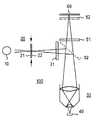
- the pattern generatorcan also comprise a mirror assembly for generating an interference pattern (cf. FIG. 5 ) or a device for direct physical or chemical influencing of the object 40 (e.g. a heating device or an ultrasound transmitter).
- the pattern generatorcan also be provided between the illumination optic 30 and the object 40 (component 20 ′′) or directly on the object 40 (component 20 ′).
- the image generatorcontains a device for reconstruction of the object image corresponding to the principles explained above.
- a specially designed circuit or an appropriately programmed computercan be used as the image generator.
- the image generatorcan contain additional memory, control, and/or display components.
- FIG. 4shows features of an optical system according to the invention using the example of an epifluorescence microscope 100 .
- the illumination device 10is formed by an intensive light source. Because high light intensities are necessary for the utilization of non-linear effects, a pulsed light source, e.g. a pulse laser or a flash lamp, is preferably used.
- the illumination devicecan, however, also be formed by a high-pressure vapor lamp (e.g. mercury vapor lamp).
- An adjustable and possibly rotatable and/or movable diffraction grating 22which is located corresponding to position 21 of the image field screen in a conjugated object plane, is provided as the pattern generator 20 (mask) as an example.
- the diffraction grating 22is a transmission grating with a grating interval of, for example, 30 ⁇ m.
- the diffraction grating 22is positioned on an adjustment drive (not shown).
- the illumination optic 30has an excitation filter 31 , a dichroic mirror 32 for coupling the excitation light into a microscope column and objective lenses 33 .
- an image of the diffraction grating 22is formed in the corresponding focal plane as illumination for the sample to be examined.
- the imaging lens 50is formed in turn by the objective lenses 33 , an emission filter 51 , and an optionally provided optic 52 for image enlargement.
- the detector device 60is a CCD detector, by which data is transmitted to the image generator (not shown).
- the diffraction grating 22can be replaced by a DMD device or an LCD matrix assembly which is positioned in the light path between the illumination device 10 and the object 40 .
- an additional reduction opticis provided between the components 20 and 40 .
- a DMD devicecomprises, for example, approximately 400 ⁇ 600 reflector elements with a pixel size of approximately 17*17 ⁇ m 2 .
- the diffraction grating 22is displaced in small steps relative to the object 40 .
- the step widthdepends on the structure dimensions of the mask and the number of partial images to be recorded and is, for example, 30/7 ⁇ m for a 30 ⁇ m structure dimension and 7 partial images.
- a displacement of the object 40can be provided for a fixed diffraction grating 22 , with this, however, requiring additional steps of image correction during the reconstruction of the object image.
- the minimum number of exposures of partial images necessary for the reconstruction of the complete imageresults from the number of unknowns of the associated equation system (see above). At least two partial image exposures are intended.
- the object 40is illuminated successively with patterns at various angles or with a mask, such as with the DMD or LCD device with a two-dimensional pattern which produces the diffraction maxima in multiple directions of the plane, in various phases in each dimension.
- the object 40is illuminated and/or excited with instantaneous intensities in such a way that the pigments in the sample become saturated, so that the desired non-linear effect for increasing the resolution capability results.
- the components of the overlapping individual orders soughtcan be calculated from the images for various phases of the excitation structure. It is also possible to reconstruct high-resolution images from exposures of partial images with varying illumination intensity. If one suppresses the zero diffraction order of the diffraction grating 21 (e.g. by masking), one thereby advantageously increases the degree of modulation of the illumination function and therefore the relative intensity in higher orders of excitation. In addition, the energy can be displaced into higher spatial frequency ranges.
- the sample (the object) 40is illuminated with laser light.
- the light source 10is preferably a pulse laser (e.g. with an optical-parametric oscillator which is pumped with a frequency-tripled NdYAG laser, or with a Ti-sapphire laser), but can also be formed by another sufficiently intensive light source.
- the pattern generator 20is formed by a group of flat mirrors 23 - 27 , which are set up for the purpose of dispersing the excitation light from the light source 10 onto various beam paths, which meet the object 40 from various directions. The excitation light is directed onto the object from two opposing sides with the semitransparent mirrors 23 and the completely reflecting mirrors 25 - 27 .
- the second semitransparent mirror 24can be provided in order to form a third excitation light path to the object 40 .
- Three excitation light beams which interfere with one anotherresult, which allows a use of the microscope 100 in extremely high-resolution 3-D microscopy.
- the mirror 24can be dispensed with. The beams interfere over a range which is of the magnitude of the co-herence length of the light source 10 .
- At least two mirrorsare positioned movably.
- the mirrors 24 and 25are displaceable for changing of the interference pattern.
- at least one electrooptical element for changing the phase of the illumination lightis provided in one of the partial light paths for changing the object conditions.
- the illumination optic 30is not shown in FIG. 5 for reasons of clarity, but can, if necessary, be left out anyway depending on the structural shape.
- the imaging optic 50comprises the objective lenses 53 , the emission filter for absorption of the excitation light 51 , and optionally a optic 52 for image enlargement.
- a CCD detector 60is again provided as the detector.
- the excitation lightcan also fall on the object 40 simultaneously from one or more directions through the objective (not shown) and/or from the side away from the objective, which is in the differential region of the excitation light beams (crosshatched region).
- the additional increase in resolution achievable through nonlinearitiescan in turn be achieved through the use of correspondingly stronger lasers and/or pulse lasers with high instantaneous intensities.
- the usage of other intensive light sourcese.g. flash light
- multiple partial imagesare recorded, each with differing interference patterns on the object 40 , and processed according to the principles for obtaining the object image explained above.
- the exemplary embodiments describedare based on the usage of the non-linear dependence of the light detected on the intensity of the excitation light due to saturation of fluorescence pigments.
- Alternative non-linear effectsare given by the saturation of the absorption of excitation light under intensive illumination, the dependence of the phase of the emitted or scattered light on the illumination intensity present in the object, which converts in the detector (e.g. the interference) or before it into a non-linear intensity dependence, SHG or THG processes, a dependence of the light characteristics of the Raman scattering on the value of one or more object conditions, temporally coherent effects (e.g.
- Rabi oscillationson atoms or molecules in the object, CARS processes, multiphoton absorptions, stimulated emissions in the object, the population of longer-lived excitation states or chemically altered states in the fluorophores before or during the illumination, radiation-free energy transfer processes, and/or physical or chemical object conditions.
- illumination deviceswith extremely short pulse lengths (e.g. ⁇ 100 fs) are preferably used. If the non-linear effect is based on stimulated emission, this is induced simultaneously or in temporal sequence.
- the stimulated emissioncan be induced at the same wavelength as that of the excitation light or at other wavelengths, e.g. at a typical fluorescence wavelength.
- the usage of energy transfer processesmeans that energy of the excitation radiation is transmitted with or without radiation by fluorophores onto neighboring fluorophore molecules and thereby a multilinear dependence of the emitted light intensity on the intensity irradiated onto the neighboring location arises.
- the physical or chemical changes of the object conditionsparticularly include the usage of the non-linear dependence of the light going out from the object points on a spatially inhomogeneous electric or magnetic field or on the pressure, shear forces, or mechanical tension relationships obtaining at the object point.
- a temperature gradient formed on the objectcan also be provided corresponding to a specific pattern, which provides the desired multilinear dependence of the light going out from the object point on the respective temperature obtaining.
- a multilinear dependence of the light going out from the object point on the chemical conditions obtaining theree.g. pH value
- an irradiation of the object with radio waves, microwaves, infrared light, x-rays, or even sound waves or ultrasound wavescan be used.
- the pattern generatoris appropriately adjusted for realization of the effects mentioned.
- the pattern generatorcan comprise an additional irradiation device whose emission is focused on the object.
- FIGS. 6 and 7illustrate simulation results for the use of a fluorescence microscope according to FIG. 4 .
- the light intensityis represented here as blackening.
- the image qualityis restricted.
- a constant background fluorescenceis assumed in the object ( FIGS. 6 a, 7 a ).
- FIG. 6 ashows the simulated object, whose illumination with the processes described and imaging with an epifluoresccnce microscope is simulated.
- the partial images b-hrepresents simulations of partial images, each taken with different phases of the illuminating line pattern.
- FIG. 6 ishows an example in which the direction of the illuminating pattern is also changed.
- the excitation intensitywas larger by a factor of 5 than the saturation intensity in this simulation.
- FIG. 7shows the associated reconstruction results.
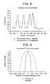
- FIG. 8illustrates the improvement of the resolution capability with the process according to the invention.
- the intensity on a reference line along the two perpendicular columns in the point matrix (above left in the original image)is illustrated in the FIGS. 7 d and 7 e.
- the solid linecorresponds to the result of the process according to the invention.
- the single pointsare clearly recognizable as maxima. With the typical process (epifluorescence followed by high frequency amplification), only the first point (partially) and a maximum between the two lowermost points are recognizable.
- An improvement of the resolution capability by a factor of more than 3results for the simulated imaging of a point.
- FIG. 9shows a lateral section through the simulated effective optical transfer function of the overall system according to FIG. 4 .
- the grating interval of the diffraction gratingis selected here in such a way that only the diffraction orders 0, +1, and ⁇ 1 of the diffraction grating can be transmitted by the objective.
- a non-linear relationship between the excitation intensity and the probability of excitation of a pigment molecule at one point in the object spaceresults. This spatially varying excitation probability is also referred to as the excitation pattern.
- the excitation probability for a specific pigment moleculeis a function of the excitation intensity, then a nonlinearity of this function leads to spatially higher harmonics of the excitation pattern also occurring in the emission pattern. Maxima in reciprocal space which lie beyond the spatial frequency limit given by the Abbe limit can then occur in the excitation pattern.
- the spatial frequency limited imaging of the multiplication of the pigment distribution with the excitation patternnow contains components analogous to a linear excitation with a pattern containing higher spatial frequencies.
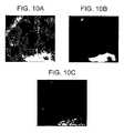
- FIG. 10shows a simulated application of the process according to the invention on a sectional image of the cell nucleus of an embryonic bovine cell recorded by means of electron microscopy.
- FIG. 10 aillustrates the inverted electron microscope section near the nuclear membrane with the nuclear matrix.
- the simulated epifluorescence microscopy exposure with deconvolutionresults in the typical image shown in FIG. 10 b.
- the image shown in FIG. 10 cresults.
- the image taken and evaluated with the method of saturated lateral modulation and subsequently deconvolvedis significantly improved compared to the typical image and comparable with the original electron microscope image.
Landscapes
- Physics & Mathematics (AREA)
- Optics & Photonics (AREA)
- General Physics & Mathematics (AREA)
- Chemical & Material Sciences (AREA)
- Analytical Chemistry (AREA)
- Engineering & Computer Science (AREA)
- Multimedia (AREA)
- Computer Vision & Pattern Recognition (AREA)
- Investigating, Analyzing Materials By Fluorescence Or Luminescence (AREA)
- Microscoopes, Condenser (AREA)
- Magnetic Resonance Imaging Apparatus (AREA)
- Silver Salt Photography Or Processing Solution Therefor (AREA)
- Transition And Organic Metals Composition Catalysts For Addition Polymerization (AREA)
- Investigating Or Analysing Materials By Optical Means (AREA)
- Length Measuring Devices By Optical Means (AREA)
Abstract
Description
Im({right arrow over (x)})=PSF({right arrow over (x)}){circle around (x)}(Bel({right arrow over (x)})·Obj({right arrow over (x)})) (1).
F(Im(x))=OTF(k)·(F(Bel(x)){circle around (x)}F(Obj(x))).
PSF({right arrow over (x)}){circle around (x)}Iem(Obj({right arrow over (x)}),{right arrow over (b)}({right arrow over (x)})) (2)
→OTF({right arrow over (k)})·F(Iem(Obj({right arrow over (x)}),{right arrow over (b)}({right arrow over (x)}))) (3).
Iem({right arrow over (x)})≅c0+c1·Obj({right arrow over (x)})+c2·b1({right arrow over (x)})+c3·Obj({right arrow over (x)})·b1({right arrow over (x)})
+c4·Obj({right arrow over (x)})2·b1({right arrow over (x)})+c5·Obj({right arrow over (x)})·b1({right arrow over (x)})2+ . . .
+c6·Obj({right arrow over (x)})·b1({right arrow over (x)})3+ . . . (4)
For simplified presentation, only one non-linear condition b1({right arrow over (x)}) is considered in equation (4). Depending on the application, further conditions could be involved in the process of the emission of light from the respective object point. In this case, corresponding terms also arise in the development according to equation (4), particularly mixed terms such as c5b·Obj({right arrow over (x)})·b1({right arrow over (x)})·b2({right arrow over (x)}). The term after C3is precisely the expression mentioned in equation (1) if b1({right arrow over (x)})=Bel({right arrow over (x)}) is assumed as the non-linear object condition. The Fourier transformation of the emitted light intensity F(Iem(Obj({right arrow over (x)}), {right arrow over (b)}({right arrow over (x)}))) thus contains, analogously to equation (1), the term c3·F(Bel({right arrow over (x)})){circle around (x)}F(Obj({right arrow over (x)})).
Claims (23)
Applications Claiming Priority (2)
| Application Number | Priority Date | Filing Date | Title |
|---|---|---|---|
| DE19908883ADE19908883A1 (en) | 1999-03-02 | 1999-03-02 | Process for increasing the resolution of optical imaging |
| PCT/EP2000/001806WO2000052512A1 (en) | 1999-03-02 | 2000-03-02 | Method and device for representing an object |
Publications (1)
| Publication Number | Publication Date |
|---|---|
| US6909105B1true US6909105B1 (en) | 2005-06-21 |
Family
ID=7899303
Family Applications (1)
| Application Number | Title | Priority Date | Filing Date |
|---|---|---|---|
| US09/914,515Expired - LifetimeUS6909105B1 (en) | 1999-03-02 | 2000-03-02 | Method and device for representing an object |
Country Status (5)
| Country | Link |
|---|---|
| US (1) | US6909105B1 (en) |
| EP (1) | EP1157297B1 (en) |
| AT (1) | ATE227434T1 (en) |
| DE (2) | DE19908883A1 (en) |
| WO (1) | WO2000052512A1 (en) |
Cited By (105)
| Publication number | Priority date | Publication date | Assignee | Title |
|---|---|---|---|---|
| US20050186491A1 (en)* | 2001-08-21 | 2005-08-25 | Asml Masktools B.V. | Method for improved lithographic patterning utilizing multiple coherency optimized exposures and high transmission attenuated PSM |
| US20070023686A1 (en)* | 2005-07-22 | 2007-02-01 | Ralf Wolleschensky | Resolution-enhanced luminescence microscopy |
| US20070091302A1 (en)* | 2005-10-24 | 2007-04-26 | General Electric Company | Methods and apparatus for inspecting an object |
| US20070223006A1 (en)* | 2006-01-19 | 2007-09-27 | The General Hospital Corporation | Systems and methods for performing rapid fluorescence lifetime, excitation and emission spectral measurements |
| US20080069467A1 (en)* | 2006-09-20 | 2008-03-20 | Carl Zeiss Imaging Solutions Gmbh A Corporation Of Germany | Methods and devices for miages processing with higher harmonics of an illumination grating |
| US20080100837A1 (en)* | 2002-01-24 | 2008-05-01 | The General Hospital Corporation | Apparatus and method for ranging and noise reduction of low coherence interferometry lci and optical coherence tomography oct signals by parallel detection of spectral bands |
| US20090131801A1 (en)* | 2007-10-12 | 2009-05-21 | The General Hospital Corporation | Systems and processes for optical imaging of luminal anatomic structures |
| US20090273777A1 (en)* | 2008-04-30 | 2009-11-05 | The General Hospital Corporation | Apparatus and method for cross axis parallel spectroscopy |
| WO2009133980A1 (en)* | 2008-05-01 | 2009-11-05 | Yong Bum Kim | Raman microscope |
| US20090279086A1 (en)* | 2006-12-18 | 2009-11-12 | Max-Planck-Gesellschaft Zur Forderung Der Wissenschaften E.V. | Method and apparatus for the high spatial resolution imaging of a structure marked with a substance |
| US7643153B2 (en) | 2003-01-24 | 2010-01-05 | The General Hospital Corporation | Apparatus and method for ranging and noise reduction of low coherence interferometry LCI and optical coherence tomography OCT signals by parallel detection of spectral bands |
| US7724786B2 (en) | 2003-06-06 | 2010-05-25 | The General Hospital Corporation | Process and apparatus for a wavelength tuning source |
| US7733497B2 (en) | 2003-10-27 | 2010-06-08 | The General Hospital Corporation | Method and apparatus for performing optical imaging using frequency-domain interferometry |
| US7772569B2 (en) | 2008-04-01 | 2010-08-10 | The Jackson Laboratory | 3D biplane microscopy |
| US7796270B2 (en) | 2006-01-10 | 2010-09-14 | The General Hospital Corporation | Systems and methods for generating data based on one or more spectrally-encoded endoscopy techniques |
| US20100283835A1 (en)* | 2007-01-11 | 2010-11-11 | Joerg Bewersdorf | Microscopic imaging techniques |
| US7847949B2 (en) | 2005-09-29 | 2010-12-07 | The General Hospital Corporation | Method and apparatus for optical imaging via spectral encoding |
| WO2010149319A1 (en) | 2009-06-26 | 2010-12-29 | Carl Zeiss Microimaging Gmbh | Method for evaluating fluorescence results in a microscope image |
| US7889348B2 (en) | 2005-10-14 | 2011-02-15 | The General Hospital Corporation | Arrangements and methods for facilitating photoluminescence imaging |
| US7920271B2 (en) | 2006-08-25 | 2011-04-05 | The General Hospital Corporation | Apparatus and methods for enhancing optical coherence tomography imaging using volumetric filtering techniques |
| US7925133B2 (en) | 2004-07-02 | 2011-04-12 | The General Hospital Corporation | Imaging system and related techniques |
| US7933021B2 (en) | 2007-10-30 | 2011-04-26 | The General Hospital Corporation | System and method for cladding mode detection |
| US7949019B2 (en) | 2007-01-19 | 2011-05-24 | The General Hospital | Wavelength tuning source based on a rotatable reflector |
| US7982879B2 (en) | 2006-02-24 | 2011-07-19 | The General Hospital Corporation | Methods and systems for performing angle-resolved fourier-domain optical coherence tomography |
| US7995210B2 (en) | 2004-11-24 | 2011-08-09 | The General Hospital Corporation | Devices and arrangements for performing coherence range imaging using a common path interferometer |
| US8018598B2 (en) | 2004-05-29 | 2011-09-13 | The General Hospital Corporation | Process, system and software arrangement for a chromatic dispersion compensation using reflective layers in optical coherence tomography (OCT) imaging |
| US20110226965A1 (en)* | 2008-11-27 | 2011-09-22 | Carl Zeiss Microimaging Gmbh | Increased resolution microscopy |
| US8040608B2 (en)* | 2007-08-31 | 2011-10-18 | The General Hospital Corporation | System and method for self-interference fluorescence microscopy, and computer-accessible medium associated therewith |
| US8045177B2 (en) | 2007-04-17 | 2011-10-25 | The General Hospital Corporation | Apparatus and methods for measuring vibrations using spectrally-encoded endoscopy |
| US8050747B2 (en) | 2001-05-01 | 2011-11-01 | The General Hospital Corporation | Method and apparatus for determination of atherosclerotic plaque type by measurement of tissue optical properties |
| WO2011135049A1 (en)* | 2010-04-28 | 2011-11-03 | Vib Vzw | Method and apparatus for the imaging of a labelled biological sample |
| US8081316B2 (en) | 2004-08-06 | 2011-12-20 | The General Hospital Corporation | Process, system and software arrangement for determining at least one location in a sample using an optical coherence tomography |
| US8097864B2 (en) | 2009-01-26 | 2012-01-17 | The General Hospital Corporation | System, method and computer-accessible medium for providing wide-field superresolution microscopy |
| US8145018B2 (en) | 2006-01-19 | 2012-03-27 | The General Hospital Corporation | Apparatus for obtaining information for a structure using spectrally-encoded endoscopy techniques and methods for producing one or more optical arrangements |
| US8174702B2 (en) | 2003-01-24 | 2012-05-08 | The General Hospital Corporation | Speckle reduction in optical coherence tomography by path length encoded angular compounding |
| US8175685B2 (en) | 2006-05-10 | 2012-05-08 | The General Hospital Corporation | Process, arrangements and systems for providing frequency domain imaging of a sample |
| US8208995B2 (en) | 2004-08-24 | 2012-06-26 | The General Hospital Corporation | Method and apparatus for imaging of vessel segments |
| USRE43875E1 (en) | 2004-09-29 | 2012-12-25 | The General Hospital Corporation | System and method for optical coherence imaging |
| US8351665B2 (en) | 2005-04-28 | 2013-01-08 | The General Hospital Corporation | Systems, processes and software arrangements for evaluating information associated with an anatomical structure by an optical coherence ranging technique |
| US20130016362A1 (en)* | 2011-07-13 | 2013-01-17 | Faro Technologies, Inc. | Device and method using a spatial light modulator to find 3d coordinates of an object |
| US20130034913A1 (en)* | 2010-04-23 | 2013-02-07 | Leica Microsystems Cms Gmbh | Method for Investigating a Specimen Containing Fluorescing Dyes with the Aid of a Microscope |
| USRE44042E1 (en) | 2004-09-10 | 2013-03-05 | The General Hospital Corporation | System and method for optical coherence imaging |
| US8593619B2 (en) | 2008-05-07 | 2013-11-26 | The General Hospital Corporation | System, method and computer-accessible medium for tracking vessel motion during three-dimensional coronary artery microscopy |
| US8704196B2 (en) | 2008-11-03 | 2014-04-22 | Carl Zeiss Microscopy Gmbh | Combination microscopy |
| US20140198201A1 (en)* | 2010-06-14 | 2014-07-17 | Howard Hughes Medical Institute | Bessel beam plane illumination microscope |
| US8804126B2 (en) | 2010-03-05 | 2014-08-12 | The General Hospital Corporation | Systems, methods and computer-accessible medium which provide microscopic images of at least one anatomical structure at a particular resolution |
| US20140235948A1 (en)* | 2013-02-19 | 2014-08-21 | The Board Of Trustees Of The Leland Stanford Junior University | Method for single-fiber microscopy using intensity-pattern sampling and optimization-based reconstruction |
| US8838213B2 (en) | 2006-10-19 | 2014-09-16 | The General Hospital Corporation | Apparatus and method for obtaining and providing imaging information associated with at least one portion of a sample, and effecting such portion(s) |
| US8861910B2 (en) | 2008-06-20 | 2014-10-14 | The General Hospital Corporation | Fused fiber optic coupler arrangement and method for use thereof |
| US8922781B2 (en) | 2004-11-29 | 2014-12-30 | The General Hospital Corporation | Arrangements, devices, endoscopes, catheters and methods for performing optical imaging by simultaneously illuminating and detecting multiple points on a sample |
| US8937724B2 (en) | 2008-12-10 | 2015-01-20 | The General Hospital Corporation | Systems and methods for extending imaging depth range of optical coherence tomography through optical sub-sampling |
| US20150035964A1 (en)* | 2011-10-12 | 2015-02-05 | Carl Zeiss Microscopy Gmbh | High-resolution luminescence microscopy |
| US8965487B2 (en) | 2004-08-24 | 2015-02-24 | The General Hospital Corporation | Process, system and software arrangement for measuring a mechanical strain and elastic properties of a sample |
| US9060689B2 (en) | 2005-06-01 | 2015-06-23 | The General Hospital Corporation | Apparatus, method and system for performing phase-resolved optical frequency domain imaging |
| US20150177128A1 (en)* | 2013-12-19 | 2015-06-25 | University Of Vienna | Quantum imaging with undetected photons |
| US9069130B2 (en) | 2010-05-03 | 2015-06-30 | The General Hospital Corporation | Apparatus, method and system for generating optical radiation from biological gain media |
| US9087368B2 (en) | 2006-01-19 | 2015-07-21 | The General Hospital Corporation | Methods and systems for optical imaging or epithelial luminal organs by beam scanning thereof |
| US9091529B2 (en) | 2011-07-14 | 2015-07-28 | Faro Technologies, Inc. | Grating-based scanner with phase and pitch adjustment |
| US9161694B2 (en) | 2005-01-24 | 2015-10-20 | The Board Of Trustees Of The Leland Stanford Junior University | Optical analysis system and approach therefor |
| US9176319B2 (en) | 2007-03-23 | 2015-11-03 | The General Hospital Corporation | Methods, arrangements and apparatus for utilizing a wavelength-swept laser using angular scanning and dispersion procedures |
| US9186067B2 (en) | 2006-02-01 | 2015-11-17 | The General Hospital Corporation | Apparatus for applying a plurality of electro-magnetic radiations to a sample |
| WO2016001910A1 (en)* | 2014-06-29 | 2016-01-07 | OPTICS 3D Ltd. | Dual structured illumination modulated in phase and intensity |
| US9254089B2 (en) | 2008-07-14 | 2016-02-09 | The General Hospital Corporation | Apparatus and methods for facilitating at least partial overlap of dispersed ration on at least one sample |
| US9282931B2 (en) | 2000-10-30 | 2016-03-15 | The General Hospital Corporation | Methods for tissue analysis |
| US9330092B2 (en) | 2011-07-19 | 2016-05-03 | The General Hospital Corporation | Systems, methods, apparatus and computer-accessible-medium for providing polarization-mode dispersion compensation in optical coherence tomography |
| US9341783B2 (en) | 2011-10-18 | 2016-05-17 | The General Hospital Corporation | Apparatus and methods for producing and/or providing recirculating optical delay(s) |
| US9351642B2 (en) | 2009-03-12 | 2016-05-31 | The General Hospital Corporation | Non-contact optical system, computer-accessible medium and method for measurement at least one mechanical property of tissue using coherent speckle technique(s) |
| US9375158B2 (en) | 2007-07-31 | 2016-06-28 | The General Hospital Corporation | Systems and methods for providing beam scan patterns for high speed doppler optical frequency domain imaging |
| US9404867B2 (en) | 2009-12-22 | 2016-08-02 | Carl Zeiss Microscopy Gmbh | Luminescence microscopy |
| US9441948B2 (en) | 2005-08-09 | 2016-09-13 | The General Hospital Corporation | Apparatus, methods and storage medium for performing polarization-based quadrature demodulation in optical coherence tomography |
| US9510758B2 (en) | 2010-10-27 | 2016-12-06 | The General Hospital Corporation | Apparatus, systems and methods for measuring blood pressure within at least one vessel |
| US9557154B2 (en) | 2010-05-25 | 2017-01-31 | The General Hospital Corporation | Systems, devices, methods, apparatus and computer-accessible media for providing optical imaging of structures and compositions |
| US9615748B2 (en) | 2009-01-20 | 2017-04-11 | The General Hospital Corporation | Endoscopic biopsy apparatus, system and method |
| US9629528B2 (en) | 2012-03-30 | 2017-04-25 | The General Hospital Corporation | Imaging system, method and distal attachment for multidirectional field of view endoscopy |
| US9651766B2 (en) | 2011-06-09 | 2017-05-16 | Carl Zeiss Microscopy Gmbh | High-resolution luminescence microscopy |
| US9668652B2 (en) | 2013-07-26 | 2017-06-06 | The General Hospital Corporation | System, apparatus and method for utilizing optical dispersion for fourier-domain optical coherence tomography |
| US9733460B2 (en) | 2014-01-08 | 2017-08-15 | The General Hospital Corporation | Method and apparatus for microscopic imaging |
| US9777053B2 (en) | 2006-02-08 | 2017-10-03 | The General Hospital Corporation | Methods, arrangements and systems for obtaining information associated with an anatomical sample using optical microscopy |
| US9784681B2 (en) | 2013-05-13 | 2017-10-10 | The General Hospital Corporation | System and method for efficient detection of the phase and amplitude of a periodic modulation associated with self-interfering fluorescence |
| US9795301B2 (en) | 2010-05-25 | 2017-10-24 | The General Hospital Corporation | Apparatus, systems, methods and computer-accessible medium for spectral analysis of optical coherence tomography images |
| US20180088246A1 (en)* | 2016-09-29 | 2018-03-29 | United States Of America As Represented By The Secretary Of The Army | Electronically collimated gamma radiation detector |
| US9968261B2 (en) | 2013-01-28 | 2018-05-15 | The General Hospital Corporation | Apparatus and method for providing diffuse spectroscopy co-registered with optical frequency domain imaging |
| US10051240B2 (en) | 2010-06-14 | 2018-08-14 | Howard Hughes Medical Institute | Structured plane illumination microscopy |
| US10117576B2 (en) | 2013-07-19 | 2018-11-06 | The General Hospital Corporation | System, method and computer accessible medium for determining eye motion by imaging retina and providing feedback for acquisition of signals from the retina |
| US10228556B2 (en) | 2014-04-04 | 2019-03-12 | The General Hospital Corporation | Apparatus and method for controlling propagation and/or transmission of electromagnetic radiation in flexible waveguide(s) |
| US10241028B2 (en) | 2011-08-25 | 2019-03-26 | The General Hospital Corporation | Methods, systems, arrangements and computer-accessible medium for providing micro-optical coherence tomography procedures |
| US10285568B2 (en) | 2010-06-03 | 2019-05-14 | The General Hospital Corporation | Apparatus and method for devices for imaging structures in or at one or more luminal organs |
| US10401607B2 (en) | 2015-09-29 | 2019-09-03 | Carl Zeiss Microscopy Gmbh | High-resolution scanning microscopy resolving at least two spectral ranges |
| US10426548B2 (en) | 2006-02-01 | 2019-10-01 | The General Hosppital Corporation | Methods and systems for providing electromagnetic radiation to at least one portion of a sample using conformal laser therapy procedures |
| US10478072B2 (en) | 2013-03-15 | 2019-11-19 | The General Hospital Corporation | Methods and system for characterizing an object |
| US10534129B2 (en) | 2007-03-30 | 2020-01-14 | The General Hospital Corporation | System and method providing intracoronary laser speckle imaging for the detection of vulnerable plaque |
| US10649188B2 (en) | 2015-07-20 | 2020-05-12 | Carl Zeiss Microscopy Gmbh | High-resolution spectrally selective scanning microscopy of a sample |
| US10736494B2 (en) | 2014-01-31 | 2020-08-11 | The General Hospital Corporation | System and method for facilitating manual and/or automatic volumetric imaging with real-time tension or force feedback using a tethered imaging device |
| US10893806B2 (en) | 2013-01-29 | 2021-01-19 | The General Hospital Corporation | Apparatus, systems and methods for providing information regarding the aortic valve |
| US10912462B2 (en) | 2014-07-25 | 2021-02-09 | The General Hospital Corporation | Apparatus, devices and methods for in vivo imaging and diagnosis |
| US11179028B2 (en) | 2013-02-01 | 2021-11-23 | The General Hospital Corporation | Objective lens arrangement for confocal endomicroscopy |
| US11204489B2 (en) | 2014-08-06 | 2021-12-21 | Carl Zeiss Microscopy Gmbh | High-resolution scanning microscopy with discrimination between at least two wavelength ranges |
| CN113933286A (en)* | 2015-12-15 | 2022-01-14 | 诺威有限公司 | Raman spectroscopy-based measurements in patterned structures |
| JP2022046447A (en)* | 2020-09-10 | 2022-03-23 | カール ツァイス マイクロスコピー ゲーエムベーハー | Ultra-high resolution evaluation method for microscope images illuminated by structured illumination method and structured illumination microscope |
| US11287627B2 (en) | 2017-06-30 | 2022-03-29 | Chrysanthe Preza | Multi-focal light-sheet structured illumination fluorescence microscopy system |
| US11452433B2 (en) | 2013-07-19 | 2022-09-27 | The General Hospital Corporation | Imaging apparatus and method which utilizes multidirectional field of view endoscopy |
| US11490826B2 (en) | 2009-07-14 | 2022-11-08 | The General Hospital Corporation | Apparatus, systems and methods for measuring flow and pressure within a vessel |
| US11490797B2 (en) | 2012-05-21 | 2022-11-08 | The General Hospital Corporation | Apparatus, device and method for capsule microscopy |
| US11573412B2 (en) | 2017-06-21 | 2023-02-07 | Carl Zeiss Microscopy Gmbh | High-resolution scanning microscopy with discrimination between at least two wave-length ranges |
| WO2023060091A1 (en)* | 2021-10-04 | 2023-04-13 | Ultima Genomics, Inc. | Enhanced resolution imaging |
Families Citing this family (22)
| Publication number | Priority date | Publication date | Assignee | Title |
|---|---|---|---|---|
| WO2003060610A1 (en)* | 2002-01-16 | 2003-07-24 | Carl Zeiss Jena Gmbh | Methods and systems for microscopic imaging |
| WO2007009812A1 (en)* | 2005-07-22 | 2007-01-25 | Carl Zeiss Microimaging Gmbh | Luminescence microscopy with enhanced resolution |
| DE102008021641A1 (en)* | 2008-04-30 | 2009-11-05 | Carl Zeiss Microlmaging Gmbh | Resolution Enhanced Luminescence Microscopy |
| DE102008049878A1 (en) | 2008-09-30 | 2010-04-01 | Carl Zeiss Microlmaging Gmbh | Improved methods and devices for microscopy with structured illumination |
| DE102009043747A1 (en) | 2009-09-30 | 2011-03-31 | Carl Zeiss Microlmaging Gmbh | Method for generating a microscope image and microscope |
| DE102009043744A1 (en) | 2009-09-30 | 2011-03-31 | Carl Zeiss Microlmaging Gmbh | Method and microscope for three-dimensional resolution-enhanced microscopy |
| EP2317362B1 (en) | 2009-10-28 | 2020-01-15 | Carl Zeiss Microscopy GmbH | Microscopic method and microscope with improved resolution |
| DE102009060793A1 (en) | 2009-12-22 | 2011-07-28 | Carl Zeiss Microlmaging GmbH, 07745 | High-resolution microscope and method for two- or three-dimensional position determination of objects |
| DE102010041794A1 (en) | 2010-09-30 | 2012-04-05 | Carl Zeiss Microlmaging Gmbh | Microscope system, microscopy method and computer program product |
| DE102011108181B4 (en)* | 2011-07-22 | 2015-02-26 | Bundesrepublik Deutschland, vertreten durch das Bundesministerium für Wirtschaft und Technologie, dieses vertreten durch den Präsidenten der Physikalisch-Technischen Bundesanstalt | Method for the spatially resolved measurement of a magnetization of a magnetic structure and magneto-optical data storage |
| DE102012204128B4 (en) | 2012-03-15 | 2023-11-16 | Carl Zeiss Microscopy Gmbh | High-resolution scanning microscopy |
| DE102013019347A1 (en) | 2013-08-15 | 2015-02-19 | Carl Zeiss Microscopy Gmbh | High-resolution scanning microscopy |
| DE102013019348A1 (en) | 2013-08-15 | 2015-02-19 | Carl Zeiss Microscopy Gmbh | High-resolution scanning microscopy |
| DE102013015932A1 (en) | 2013-09-19 | 2015-03-19 | Carl Zeiss Microscopy Gmbh | High-resolution scanning microscopy |
| DE102013015933A1 (en) | 2013-09-19 | 2015-03-19 | Carl Zeiss Microscopy Gmbh | High-resolution scanning microscopy |
| DE102013015931B4 (en) | 2013-09-19 | 2024-05-08 | Carl Zeiss Microscopy Gmbh | Microscope and method for high-resolution scanning microscopes |
| DE102015116598B4 (en) | 2015-09-30 | 2024-10-24 | Carl Zeiss Microscopy Gmbh | Method and microscope for high-resolution imaging using SIM |
| DE102015015497A1 (en) | 2015-11-30 | 2017-06-14 | Horst Wochnowski | Various applications of high-resolution fluorescence-based microscopy methods (RESOLFT / STED et al.) Based methods, such as fluorescence-based nanostructuring |
| DE102016007839A1 (en) | 2016-06-28 | 2017-12-28 | Horst Wochnowski | High-resolution method for microscopy and nanostructuring of substrate surfaces based on the SIM method (Structured Illumination Microscopy) |
| DE102018124984A1 (en) | 2018-10-10 | 2020-04-16 | Friedrich-Schiller-Universität Jena | Method and device for high-resolution fluorescence microscopy |
| DE102018009056A1 (en) | 2018-11-12 | 2020-05-14 | Carl Zeiss Microscopy Gmbh | Accelerated methods and devices for three-dimensional microscopy with structured illumination |
| DE102019129932B4 (en)* | 2019-11-06 | 2023-12-21 | Technische Universität Braunschweig | Optical detection device and method for operating an optical detection device |
Citations (22)
| Publication number | Priority date | Publication date | Assignee | Title |
|---|---|---|---|---|
| US4525858A (en) | 1983-01-03 | 1985-06-25 | General Electric Company | Method and apparatus for reconstruction of three-dimensional surfaces from interference fringes |
| US4621911A (en) | 1985-03-12 | 1986-11-11 | Carnegie-Mellon University | Standing wave luminescence microscopy |
| US4631581A (en) | 1984-03-15 | 1986-12-23 | Sarastro Ab | Method and apparatus for microphotometering microscope specimens |
| EP0352975A2 (en) | 1988-07-26 | 1990-01-31 | AT&T Corp. | Resolution doubling lithography technique |
| US4929951A (en) | 1988-12-23 | 1990-05-29 | Hughes Aircraft Company | Apparatus and method for transform space scanning imaging |
| WO1991007682A1 (en) | 1989-11-22 | 1991-05-30 | The Secretary Of State For Defence In Her Britannic Majesty's Government Of The United Kingdom Of Great Britain And Northern Ireland | Phase measuring scanning optical microscope |
| US5034613A (en) | 1989-11-14 | 1991-07-23 | Cornell Research Foundation, Inc. | Two-photon laser microscopy |
| EP0491289A1 (en) | 1990-12-18 | 1992-06-24 | Stefan Dr. Hell | Double-confocal scanning microscope |
| EP0562488A1 (en) | 1992-03-19 | 1993-09-29 | Matsushita Electric Industrial Co., Ltd. | Superresolution scanning optical device |
| DE4326473A1 (en) | 1993-08-06 | 1995-02-09 | European Molecular Biology Lab Embl | Scanning microscope for viewing at an angle relative to the illumination |
| WO1997006509A1 (en) | 1995-08-03 | 1997-02-20 | Gim Systems Ltd. | Imaging measurement system |
| WO1997011355A1 (en) | 1995-09-19 | 1997-03-27 | Cornell Research Foundation, Inc. | Multi-photon laser microscopy |
| US5640270A (en)* | 1996-03-11 | 1997-06-17 | Wyko Corporation | Orthogonal-scanning microscope objective for vertical-scanning and phase-shifting interferometry |
| WO1997031282A1 (en) | 1996-02-22 | 1997-08-28 | Isis Innovation Limited | Confocal microscope |
| US5671085A (en) | 1995-02-03 | 1997-09-23 | The Regents Of The University Of California | Method and apparatus for three-dimensional microscopy with enhanced depth resolution |
| US5731588A (en) | 1994-02-01 | 1998-03-24 | Hell; Stefan | Process and device for optically measuring a point on a sample with high local resolution |
| US5777732A (en) | 1994-04-28 | 1998-07-07 | Hanninen; Pekka | Luminescence-scanning microscopy process and a luminescence scanning microscope utilizing picosecond or greater pulse lasers |
| US5796112A (en) | 1993-06-03 | 1998-08-18 | Hamamatsu Photonics K.K. | Laser scanning optical system and laser scanning optical apparatus |
| US5801881A (en) | 1993-02-05 | 1998-09-01 | Carnegie Mellon University | Field synthesis and optical subsectioning for standing wave microscopy |
| WO1998045745A1 (en) | 1997-04-04 | 1998-10-15 | Isis Innovation Limited | Microscopy imaging apparatus and method |
| US5828459A (en) | 1996-05-03 | 1998-10-27 | Yeda Research And Development Co. Ltd. | Apparatus and method for scanning laser microscopy |
| US5841149A (en)* | 1994-04-11 | 1998-11-24 | Leica Mikroskopie Systeme Ag | Method of determining the distance of a feature on an object from a microscope, and a device for carrying out the method |
- 1999
- 1999-03-02DEDE19908883Apatent/DE19908883A1/ennot_activeWithdrawn
- 2000
- 2000-03-02USUS09/914,515patent/US6909105B1/ennot_activeExpired - Lifetime
- 2000-03-02DEDE50000729Tpatent/DE50000729D1/ennot_activeExpired - Lifetime
- 2000-03-02EPEP00912537Apatent/EP1157297B1/ennot_activeExpired - Lifetime
- 2000-03-02ATAT00912537Tpatent/ATE227434T1/ennot_activeIP Right Cessation
- 2000-03-02WOPCT/EP2000/001806patent/WO2000052512A1/enactiveIP Right Grant
Patent Citations (23)
| Publication number | Priority date | Publication date | Assignee | Title |
|---|---|---|---|---|
| US4525858A (en) | 1983-01-03 | 1985-06-25 | General Electric Company | Method and apparatus for reconstruction of three-dimensional surfaces from interference fringes |
| US4631581A (en) | 1984-03-15 | 1986-12-23 | Sarastro Ab | Method and apparatus for microphotometering microscope specimens |
| US4621911A (en) | 1985-03-12 | 1986-11-11 | Carnegie-Mellon University | Standing wave luminescence microscopy |
| EP0352975A2 (en) | 1988-07-26 | 1990-01-31 | AT&T Corp. | Resolution doubling lithography technique |
| US4929951A (en) | 1988-12-23 | 1990-05-29 | Hughes Aircraft Company | Apparatus and method for transform space scanning imaging |
| US5034613A (en) | 1989-11-14 | 1991-07-23 | Cornell Research Foundation, Inc. | Two-photon laser microscopy |
| WO1991007682A1 (en) | 1989-11-22 | 1991-05-30 | The Secretary Of State For Defence In Her Britannic Majesty's Government Of The United Kingdom Of Great Britain And Northern Ireland | Phase measuring scanning optical microscope |
| EP0491289A1 (en) | 1990-12-18 | 1992-06-24 | Stefan Dr. Hell | Double-confocal scanning microscope |
| EP0562488A1 (en) | 1992-03-19 | 1993-09-29 | Matsushita Electric Industrial Co., Ltd. | Superresolution scanning optical device |
| US5801881A (en) | 1993-02-05 | 1998-09-01 | Carnegie Mellon University | Field synthesis and optical subsectioning for standing wave microscopy |
| US5796112A (en) | 1993-06-03 | 1998-08-18 | Hamamatsu Photonics K.K. | Laser scanning optical system and laser scanning optical apparatus |
| DE4326473A1 (en) | 1993-08-06 | 1995-02-09 | European Molecular Biology Lab Embl | Scanning microscope for viewing at an angle relative to the illumination |
| US5731588A (en) | 1994-02-01 | 1998-03-24 | Hell; Stefan | Process and device for optically measuring a point on a sample with high local resolution |
| US5841149A (en)* | 1994-04-11 | 1998-11-24 | Leica Mikroskopie Systeme Ag | Method of determining the distance of a feature on an object from a microscope, and a device for carrying out the method |
| US5777732A (en) | 1994-04-28 | 1998-07-07 | Hanninen; Pekka | Luminescence-scanning microscopy process and a luminescence scanning microscope utilizing picosecond or greater pulse lasers |
| US5671085A (en) | 1995-02-03 | 1997-09-23 | The Regents Of The University Of California | Method and apparatus for three-dimensional microscopy with enhanced depth resolution |
| WO1997006509A1 (en) | 1995-08-03 | 1997-02-20 | Gim Systems Ltd. | Imaging measurement system |
| US5867604A (en) | 1995-08-03 | 1999-02-02 | Ben-Levy; Meir | Imaging measurement system |
| WO1997011355A1 (en) | 1995-09-19 | 1997-03-27 | Cornell Research Foundation, Inc. | Multi-photon laser microscopy |
| WO1997031282A1 (en) | 1996-02-22 | 1997-08-28 | Isis Innovation Limited | Confocal microscope |
| US5640270A (en)* | 1996-03-11 | 1997-06-17 | Wyko Corporation | Orthogonal-scanning microscope objective for vertical-scanning and phase-shifting interferometry |
| US5828459A (en) | 1996-05-03 | 1998-10-27 | Yeda Research And Development Co. Ltd. | Apparatus and method for scanning laser microscopy |
| WO1998045745A1 (en) | 1997-04-04 | 1998-10-15 | Isis Innovation Limited | Microscopy imaging apparatus and method |
Non-Patent Citations (14)
| Title |
|---|
| David R. Sandison et al., Quantitative Fluorescence Confocal Laser Scanning Microscopy (CLSM), James B. Pawley, editor, Handbook of Biological Confocal Microscopy, Chapter 3:47-50, 1995. |
| Ernst H.K. Stelzer et al., Fundamental Reduction of the Observation Volume in Far-Field Light Microscopy by Detection Orthogonal to the Illumination Axis: Confocal Theta Microscopy, Optics Communications, 111:536-547, 1994. |
| Frederick Lanni et al., Excitation Field Synthesis as a Means for Obtaining Enhanced Axial Resolution in Fluorescence Microscopes, Bioimaging 1 (1993) 187-196. |
| M.D. Duncan, Molecular Discrimination and Contrast Enhancement Using a Scanning Coherent Anti-Stokes Raman Microscope, Optics Communications, vol. 50, No. 5:307-312, Jul. 1984. |
| Mats G.L. Gustafsson et al., 3D Widefield Microscopy With Two Objective Lenses: Experimental Verification of Improved Axial Resolution, Proceedings of SPIE, 2655:62-66, 1996. |
| R. Heintzmann et al., Laterally Modulated Excitation Microscopy: Improvement of Resolution by Using a Diffraction Grating, Proceedings of SPIE, 3568:185-196, 1999. |
| R. Ju{hacek over (skaitis et al., Efficient Real-Time Confocal Microscopy With White Light Sources, Nature, vol. 383:804-806, Oct. 1996. |
| Robert Windecker et al., Three-Dimensional Topometry with Stereo Microscopes, Optical Engineering, 36(12):3372-3377, Dec. 1997. |
| Roger Y. Tsien et al., Fluorophores for Confocal Microscopy: Photophysics and Photochemistry, James B. Pawley, editor, Handbook of Biological Confocal Microscopy, Chapter 16:267-268, 1995. |
| S. W. Hell et al., Ground-State-Depletion Fluorescence Microscopy: A Concept for Breaking the Diffraction Resolution Limit, Applied Physics B 60, 495-497 (1995). |
| Stefan Hell et al., Properties of a 4Pi Confocal Fluorescence Microscope, Journal of the Optical Society of America, vol. 9, No. 12:2159-2166, Dec. 1992. |
| Steffen Lindek et al., Two New High-Resolution Confocal Fluorescence Microscopies (4Pi, Theta) With One-and Two-Photon Excitation, James B. Pawley, editor, Handbook of Biological Confocal Microscopy, Chapter 26:417-430, 1995. |
| T. Wilson et al., A New Approach to Three Dimensional Imaging in Microscopy, Cell Vision, vol. 4, No. 2, 231, Mar. 1997. |
| T. Wilson et al., An Aperture Correlation Approach to Confocal Microscopy, Proceedings of SPIE, vol. 2984:21-23, 1997. |
Cited By (186)
| Publication number | Priority date | Publication date | Assignee | Title |
|---|---|---|---|---|
| US9282931B2 (en) | 2000-10-30 | 2016-03-15 | The General Hospital Corporation | Methods for tissue analysis |
| US8050747B2 (en) | 2001-05-01 | 2011-11-01 | The General Hospital Corporation | Method and apparatus for determination of atherosclerotic plaque type by measurement of tissue optical properties |
| US8150496B2 (en) | 2001-05-01 | 2012-04-03 | The General Hospital Corporation | Method and apparatus for determination of atherosclerotic plaque type by measurement of tissue optical properties |
| US7523438B2 (en)* | 2001-08-21 | 2009-04-21 | Asml Masktools B.V. | Method for improved lithographic patterning utilizing optimized illumination conditions and high transmission attenuated PSM |
| US20050186491A1 (en)* | 2001-08-21 | 2005-08-25 | Asml Masktools B.V. | Method for improved lithographic patterning utilizing multiple coherency optimized exposures and high transmission attenuated PSM |
| US7872757B2 (en) | 2002-01-24 | 2011-01-18 | The General Hospital Corporation | Apparatus and method for ranging and noise reduction of low coherence interferometry LCI and optical coherence tomography OCT signals by parallel detection of spectral bands |
| US20080100837A1 (en)* | 2002-01-24 | 2008-05-01 | The General Hospital Corporation | Apparatus and method for ranging and noise reduction of low coherence interferometry lci and optical coherence tomography oct signals by parallel detection of spectral bands |
| US20080152353A1 (en)* | 2002-01-24 | 2008-06-26 | The General Hospital Corporation | Apparatus and method for ranging and noise reduction of low coherence interferometry lci and optical coherence tomography oct signals by parallel detection of spectral bands |
| US7643152B2 (en) | 2002-01-24 | 2010-01-05 | The General Hospital Corporation | Apparatus and method for ranging and noise reduction of low coherence interferometry LCI and optical coherence tomography OCT signals by parallel detection of spectral bands |
| US7630083B2 (en) | 2002-01-24 | 2009-12-08 | The General Hospital Corporation | Apparatus and method for ranging and noise reduction of low coherence interferometry LCI and optical coherence tomography OCT signals by parallel detection of spectral bands |
| US9226665B2 (en) | 2003-01-24 | 2016-01-05 | The General Hospital Corporation | Speckle reduction in optical coherence tomography by path length encoded angular compounding |
| US8054468B2 (en) | 2003-01-24 | 2011-11-08 | The General Hospital Corporation | Apparatus and method for ranging and noise reduction of low coherence interferometry LCI and optical coherence tomography OCT signals by parallel detection of spectral bands |
| US8174702B2 (en) | 2003-01-24 | 2012-05-08 | The General Hospital Corporation | Speckle reduction in optical coherence tomography by path length encoded angular compounding |
| US8559012B2 (en) | 2003-01-24 | 2013-10-15 | The General Hospital Corporation | Speckle reduction in optical coherence tomography by path length encoded angular compounding |
| US7643153B2 (en) | 2003-01-24 | 2010-01-05 | The General Hospital Corporation | Apparatus and method for ranging and noise reduction of low coherence interferometry LCI and optical coherence tomography OCT signals by parallel detection of spectral bands |
| US7724786B2 (en) | 2003-06-06 | 2010-05-25 | The General Hospital Corporation | Process and apparatus for a wavelength tuning source |
| USRE47675E1 (en) | 2003-06-06 | 2019-10-29 | The General Hospital Corporation | Process and apparatus for a wavelength tuning source |
| US7995627B2 (en) | 2003-06-06 | 2011-08-09 | The General Hospital Corporation | Process and apparatus for a wavelength tuning source |
| US20100254414A1 (en)* | 2003-06-06 | 2010-10-07 | The General Hospital Corporation | Process and apparatus for a wavelength tuning source |
| US8416818B2 (en) | 2003-06-06 | 2013-04-09 | The General Hospital Corporation | Process and apparatus for a wavelength tuning source |
| US8705046B2 (en) | 2003-10-27 | 2014-04-22 | The General Hospital Corporation | Method and apparatus for performing optical imaging using frequency-domain interferometry |
| US7969578B2 (en) | 2003-10-27 | 2011-06-28 | The General Hospital Corporation | Method and apparatus for performing optical imaging using frequency-domain interferometry |
| US7733497B2 (en) | 2003-10-27 | 2010-06-08 | The General Hospital Corporation | Method and apparatus for performing optical imaging using frequency-domain interferometry |
| US8384909B2 (en) | 2003-10-27 | 2013-02-26 | The General Hospital Corporation | Method and apparatus for performing optical imaging using frequency-domain interferometry |
| US8355138B2 (en) | 2003-10-27 | 2013-01-15 | The General Hospital Corporation | Method and apparatus for performing optical imaging using frequency-domain interferometry |
| US9377290B2 (en) | 2003-10-27 | 2016-06-28 | The General Hospital Corporation | Method and apparatus for performing optical imaging using frequency-domain interferometry |
| US9812846B2 (en) | 2003-10-27 | 2017-11-07 | The General Hospital Corporation | Method and apparatus for performing optical imaging using frequency-domain interferometry |
| US8018598B2 (en) | 2004-05-29 | 2011-09-13 | The General Hospital Corporation | Process, system and software arrangement for a chromatic dispersion compensation using reflective layers in optical coherence tomography (OCT) imaging |
| US8676013B2 (en) | 2004-07-02 | 2014-03-18 | The General Hospital Corporation | Imaging system using and related techniques |
| US9664615B2 (en) | 2004-07-02 | 2017-05-30 | The General Hospital Corporation | Imaging system and related techniques |
| US8369669B2 (en) | 2004-07-02 | 2013-02-05 | The General Hospital Corporation | Imaging system and related techniques |
| US7925133B2 (en) | 2004-07-02 | 2011-04-12 | The General Hospital Corporation | Imaging system and related techniques |
| US8081316B2 (en) | 2004-08-06 | 2011-12-20 | The General Hospital Corporation | Process, system and software arrangement for determining at least one location in a sample using an optical coherence tomography |
| US9226660B2 (en) | 2004-08-06 | 2016-01-05 | The General Hospital Corporation | Process, system and software arrangement for determining at least one location in a sample using an optical coherence tomography |
| US9254102B2 (en) | 2004-08-24 | 2016-02-09 | The General Hospital Corporation | Method and apparatus for imaging of vessel segments |
| US8965487B2 (en) | 2004-08-24 | 2015-02-24 | The General Hospital Corporation | Process, system and software arrangement for measuring a mechanical strain and elastic properties of a sample |
| US8208995B2 (en) | 2004-08-24 | 2012-06-26 | The General Hospital Corporation | Method and apparatus for imaging of vessel segments |
| US9763623B2 (en) | 2004-08-24 | 2017-09-19 | The General Hospital Corporation | Method and apparatus for imaging of vessel segments |
| USRE44042E1 (en) | 2004-09-10 | 2013-03-05 | The General Hospital Corporation | System and method for optical coherence imaging |
| USRE43875E1 (en) | 2004-09-29 | 2012-12-25 | The General Hospital Corporation | System and method for optical coherence imaging |
| USRE45512E1 (en) | 2004-09-29 | 2015-05-12 | The General Hospital Corporation | System and method for optical coherence imaging |
| US7995210B2 (en) | 2004-11-24 | 2011-08-09 | The General Hospital Corporation | Devices and arrangements for performing coherence range imaging using a common path interferometer |
| US8922781B2 (en) | 2004-11-29 | 2014-12-30 | The General Hospital Corporation | Arrangements, devices, endoscopes, catheters and methods for performing optical imaging by simultaneously illuminating and detecting multiple points on a sample |
| US9161694B2 (en) | 2005-01-24 | 2015-10-20 | The Board Of Trustees Of The Leland Stanford Junior University | Optical analysis system and approach therefor |
| US9839361B2 (en) | 2005-01-24 | 2017-12-12 | The Board Of Trustees Of The Leland Stanford Junior University | Optical analysis system and approach therefor |
| US9326682B2 (en) | 2005-04-28 | 2016-05-03 | The General Hospital Corporation | Systems, processes and software arrangements for evaluating information associated with an anatomical structure by an optical coherence ranging technique |
| US8351665B2 (en) | 2005-04-28 | 2013-01-08 | The General Hospital Corporation | Systems, processes and software arrangements for evaluating information associated with an anatomical structure by an optical coherence ranging technique |
| US9060689B2 (en) | 2005-06-01 | 2015-06-23 | The General Hospital Corporation | Apparatus, method and system for performing phase-resolved optical frequency domain imaging |
| US20070023686A1 (en)* | 2005-07-22 | 2007-02-01 | Ralf Wolleschensky | Resolution-enhanced luminescence microscopy |
| US7485875B2 (en) | 2005-07-22 | 2009-02-03 | Carl Zeiss Microimaging Gmbh | Resolution-enhanced luminescence microscopy |
| US9441948B2 (en) | 2005-08-09 | 2016-09-13 | The General Hospital Corporation | Apparatus, methods and storage medium for performing polarization-based quadrature demodulation in optical coherence tomography |
| US8760663B2 (en) | 2005-09-29 | 2014-06-24 | The General Hospital Corporation | Method and apparatus for optical imaging via spectral encoding |
| US8384907B2 (en) | 2005-09-29 | 2013-02-26 | The General Hospital Corporation | Method and apparatus for optical imaging via spectral encoding |
| US8149418B2 (en) | 2005-09-29 | 2012-04-03 | The General Hospital Corporation | Method and apparatus for optical imaging via spectral encoding |
| US8928889B2 (en) | 2005-09-29 | 2015-01-06 | The General Hospital Corporation | Arrangements and methods for providing multimodality microscopic imaging of one or more biological structures |
| US9304121B2 (en) | 2005-09-29 | 2016-04-05 | The General Hospital Corporation | Method and apparatus for optical imaging via spectral encoding |
| US7847949B2 (en) | 2005-09-29 | 2010-12-07 | The General Hospital Corporation | Method and apparatus for optical imaging via spectral encoding |
| US9513276B2 (en) | 2005-09-29 | 2016-12-06 | The General Hospital Corporation | Method and apparatus for optical imaging via spectral encoding |
| US8289522B2 (en) | 2005-09-29 | 2012-10-16 | The General Hospital Corporation | Arrangements and methods for providing multimodality microscopic imaging of one or more biological structures |
| US7889348B2 (en) | 2005-10-14 | 2011-02-15 | The General Hospital Corporation | Arrangements and methods for facilitating photoluminescence imaging |
| CN1955720B (en)* | 2005-10-24 | 2010-12-15 | 通用电气公司 | Methods and apparatus for inspecting an object |
| US20070091302A1 (en)* | 2005-10-24 | 2007-04-26 | General Electric Company | Methods and apparatus for inspecting an object |
| US7492450B2 (en)* | 2005-10-24 | 2009-02-17 | General Electric Company | Methods and apparatus for inspecting an object |
| US7796270B2 (en) | 2006-01-10 | 2010-09-14 | The General Hospital Corporation | Systems and methods for generating data based on one or more spectrally-encoded endoscopy techniques |
| US20070223006A1 (en)* | 2006-01-19 | 2007-09-27 | The General Hospital Corporation | Systems and methods for performing rapid fluorescence lifetime, excitation and emission spectral measurements |
| US10987000B2 (en) | 2006-01-19 | 2021-04-27 | The General Hospital Corporation | Methods and systems for optical imaging or epithelial luminal organs by beam scanning thereof |
| US9646377B2 (en) | 2006-01-19 | 2017-05-09 | The General Hospital Corporation | Methods and systems for optical imaging or epithelial luminal organs by beam scanning thereof |
| US8818149B2 (en) | 2006-01-19 | 2014-08-26 | The General Hospital Corporation | Spectrally-encoded endoscopy techniques, apparatus and methods |
| US8145018B2 (en) | 2006-01-19 | 2012-03-27 | The General Hospital Corporation | Apparatus for obtaining information for a structure using spectrally-encoded endoscopy techniques and methods for producing one or more optical arrangements |
| US9087368B2 (en) | 2006-01-19 | 2015-07-21 | The General Hospital Corporation | Methods and systems for optical imaging or epithelial luminal organs by beam scanning thereof |
| US9516997B2 (en) | 2006-01-19 | 2016-12-13 | The General Hospital Corporation | Spectrally-encoded endoscopy techniques, apparatus and methods |
| US9791317B2 (en) | 2006-01-19 | 2017-10-17 | The General Hospital Corporation | Spectrally-encoded endoscopy techniques and methods |
| US9186067B2 (en) | 2006-02-01 | 2015-11-17 | The General Hospital Corporation | Apparatus for applying a plurality of electro-magnetic radiations to a sample |
| US9186066B2 (en) | 2006-02-01 | 2015-11-17 | The General Hospital Corporation | Apparatus for applying a plurality of electro-magnetic radiations to a sample |
| US10426548B2 (en) | 2006-02-01 | 2019-10-01 | The General Hosppital Corporation | Methods and systems for providing electromagnetic radiation to at least one portion of a sample using conformal laser therapy procedures |
| US9777053B2 (en) | 2006-02-08 | 2017-10-03 | The General Hospital Corporation | Methods, arrangements and systems for obtaining information associated with an anatomical sample using optical microscopy |
| USRE46412E1 (en) | 2006-02-24 | 2017-05-23 | The General Hospital Corporation | Methods and systems for performing angle-resolved Fourier-domain optical coherence tomography |
| US7982879B2 (en) | 2006-02-24 | 2011-07-19 | The General Hospital Corporation | Methods and systems for performing angle-resolved fourier-domain optical coherence tomography |
| US9364143B2 (en) | 2006-05-10 | 2016-06-14 | The General Hospital Corporation | Process, arrangements and systems for providing frequency domain imaging of a sample |
| US8175685B2 (en) | 2006-05-10 | 2012-05-08 | The General Hospital Corporation | Process, arrangements and systems for providing frequency domain imaging of a sample |
| US10413175B2 (en) | 2006-05-10 | 2019-09-17 | The General Hospital Corporation | Process, arrangements and systems for providing frequency domain imaging of a sample |
| US7920271B2 (en) | 2006-08-25 | 2011-04-05 | The General Hospital Corporation | Apparatus and methods for enhancing optical coherence tomography imaging using volumetric filtering techniques |
| DE102006044229B4 (en) | 2006-09-20 | 2023-09-28 | Carl Zeiss Microscopy Gmbh | Method and device for image processing with higher harmonics of a lighting grid |
| US8160379B2 (en)* | 2006-09-20 | 2012-04-17 | Carl Zeiss Imaging Solutions Gmbh | Methods and devices for image processing with higher harmonics of an illumination grating |
| US20080069467A1 (en)* | 2006-09-20 | 2008-03-20 | Carl Zeiss Imaging Solutions Gmbh A Corporation Of Germany | Methods and devices for miages processing with higher harmonics of an illumination grating |
| US9968245B2 (en) | 2006-10-19 | 2018-05-15 | The General Hospital Corporation | Apparatus and method for obtaining and providing imaging information associated with at least one portion of a sample, and effecting such portion(s) |
| US8838213B2 (en) | 2006-10-19 | 2014-09-16 | The General Hospital Corporation | Apparatus and method for obtaining and providing imaging information associated with at least one portion of a sample, and effecting such portion(s) |
| US7894067B2 (en) | 2006-12-18 | 2011-02-22 | MAX-PLANCK-Gesellschaft zur Förderung der Wissenschaften e.V. | Method and apparatus for the high spatial resolution imaging of a structure marked with a substance |
| US20090279086A1 (en)* | 2006-12-18 | 2009-11-12 | Max-Planck-Gesellschaft Zur Forderung Der Wissenschaften E.V. | Method and apparatus for the high spatial resolution imaging of a structure marked with a substance |
| US8217992B2 (en) | 2007-01-11 | 2012-07-10 | The Jackson Laboratory | Microscopic imaging techniques |
| US20100283835A1 (en)* | 2007-01-11 | 2010-11-11 | Joerg Bewersdorf | Microscopic imaging techniques |
| US7949019B2 (en) | 2007-01-19 | 2011-05-24 | The General Hospital | Wavelength tuning source based on a rotatable reflector |
| US9176319B2 (en) | 2007-03-23 | 2015-11-03 | The General Hospital Corporation | Methods, arrangements and apparatus for utilizing a wavelength-swept laser using angular scanning and dispersion procedures |
| US10534129B2 (en) | 2007-03-30 | 2020-01-14 | The General Hospital Corporation | System and method providing intracoronary laser speckle imaging for the detection of vulnerable plaque |
| US8045177B2 (en) | 2007-04-17 | 2011-10-25 | The General Hospital Corporation | Apparatus and methods for measuring vibrations using spectrally-encoded endoscopy |
| US9375158B2 (en) | 2007-07-31 | 2016-06-28 | The General Hospital Corporation | Systems and methods for providing beam scan patterns for high speed doppler optical frequency domain imaging |
| US8040608B2 (en)* | 2007-08-31 | 2011-10-18 | The General Hospital Corporation | System and method for self-interference fluorescence microscopy, and computer-accessible medium associated therewith |
| US20090131801A1 (en)* | 2007-10-12 | 2009-05-21 | The General Hospital Corporation | Systems and processes for optical imaging of luminal anatomic structures |
| US7933021B2 (en) | 2007-10-30 | 2011-04-26 | The General Hospital Corporation | System and method for cladding mode detection |
| US7772569B2 (en) | 2008-04-01 | 2010-08-10 | The Jackson Laboratory | 3D biplane microscopy |
| US20100265318A1 (en)* | 2008-04-01 | 2010-10-21 | The Jackson Laboratory | 3D Biplane Microscopy |
| US7880149B2 (en) | 2008-04-01 | 2011-02-01 | The Jackson Laboratory | 3D biplane microscopy |
| US20110025831A1 (en)* | 2008-04-01 | 2011-02-03 | The Jackson Laboratory | 3D Biplane Microscopy |
| US20090273777A1 (en)* | 2008-04-30 | 2009-11-05 | The General Hospital Corporation | Apparatus and method for cross axis parallel spectroscopy |
| US7898656B2 (en) | 2008-04-30 | 2011-03-01 | The General Hospital Corporation | Apparatus and method for cross axis parallel spectroscopy |
| KR100936645B1 (en) | 2008-05-01 | 2010-01-14 | 김영범 | Raman microscope |
| WO2009133980A1 (en)* | 2008-05-01 | 2009-11-05 | Yong Bum Kim | Raman microscope |
| US8593619B2 (en) | 2008-05-07 | 2013-11-26 | The General Hospital Corporation | System, method and computer-accessible medium for tracking vessel motion during three-dimensional coronary artery microscopy |
| US9173572B2 (en) | 2008-05-07 | 2015-11-03 | The General Hospital Corporation | System, method and computer-accessible medium for tracking vessel motion during three-dimensional coronary artery microscopy |
| US8861910B2 (en) | 2008-06-20 | 2014-10-14 | The General Hospital Corporation | Fused fiber optic coupler arrangement and method for use thereof |
| US9254089B2 (en) | 2008-07-14 | 2016-02-09 | The General Hospital Corporation | Apparatus and methods for facilitating at least partial overlap of dispersed ration on at least one sample |
| US10835110B2 (en) | 2008-07-14 | 2020-11-17 | The General Hospital Corporation | Apparatus and method for facilitating at least partial overlap of dispersed ration on at least one sample |
| US8704196B2 (en) | 2008-11-03 | 2014-04-22 | Carl Zeiss Microscopy Gmbh | Combination microscopy |
| US8610086B2 (en) | 2008-11-27 | 2013-12-17 | Carl Zeiss Microscopy Gmbh | Increased resolution microscopy |
| US20110226965A1 (en)* | 2008-11-27 | 2011-09-22 | Carl Zeiss Microimaging Gmbh | Increased resolution microscopy |
| US8937724B2 (en) | 2008-12-10 | 2015-01-20 | The General Hospital Corporation | Systems and methods for extending imaging depth range of optical coherence tomography through optical sub-sampling |
| US9615748B2 (en) | 2009-01-20 | 2017-04-11 | The General Hospital Corporation | Endoscopic biopsy apparatus, system and method |
| US8097864B2 (en) | 2009-01-26 | 2012-01-17 | The General Hospital Corporation | System, method and computer-accessible medium for providing wide-field superresolution microscopy |
| US9351642B2 (en) | 2009-03-12 | 2016-05-31 | The General Hospital Corporation | Non-contact optical system, computer-accessible medium and method for measurement at least one mechanical property of tissue using coherent speckle technique(s) |
| DE102009031231A1 (en) | 2009-06-26 | 2010-12-30 | Carl Zeiss Microlmaging Gmbh | Methods and arrangements for fluorescence microscopy |
| US8988771B2 (en) | 2009-06-26 | 2015-03-24 | Carl Zeiss Microscopy Gmbh | Method for evaluating fluorescence results in a microscope image |
| WO2010149319A1 (en) | 2009-06-26 | 2010-12-29 | Carl Zeiss Microimaging Gmbh | Method for evaluating fluorescence results in a microscope image |
| US11490826B2 (en) | 2009-07-14 | 2022-11-08 | The General Hospital Corporation | Apparatus, systems and methods for measuring flow and pressure within a vessel |
| US9404867B2 (en) | 2009-12-22 | 2016-08-02 | Carl Zeiss Microscopy Gmbh | Luminescence microscopy |
| US9642531B2 (en) | 2010-03-05 | 2017-05-09 | The General Hospital Corporation | Systems, methods and computer-accessible medium which provide microscopic images of at least one anatomical structure at a particular resolution |
| US10463254B2 (en) | 2010-03-05 | 2019-11-05 | The General Hospital Corporation | Light tunnel and lens which provide extended focal depth of at least one anatomical structure at a particular resolution |
| US8896838B2 (en) | 2010-03-05 | 2014-11-25 | The General Hospital Corporation | Systems, methods and computer-accessible medium which provide microscopic images of at least one anatomical structure at a particular resolution |
| US9408539B2 (en) | 2010-03-05 | 2016-08-09 | The General Hospital Corporation | Systems, methods and computer-accessible medium which provide microscopic images of at least one anatomical structure at a particular resolution |
| US9081148B2 (en) | 2010-03-05 | 2015-07-14 | The General Hospital Corporation | Systems, methods and computer-accessible medium which provide microscopic images of at least one anatomical structure at a particular resolution |
| US8804126B2 (en) | 2010-03-05 | 2014-08-12 | The General Hospital Corporation | Systems, methods and computer-accessible medium which provide microscopic images of at least one anatomical structure at a particular resolution |
| US20130034913A1 (en)* | 2010-04-23 | 2013-02-07 | Leica Microsystems Cms Gmbh | Method for Investigating a Specimen Containing Fluorescing Dyes with the Aid of a Microscope |
| US9569828B2 (en) | 2010-04-28 | 2017-02-14 | Vib Vzw | Method and apparatus for the imaging of a labeled biological sample |
| WO2011135049A1 (en)* | 2010-04-28 | 2011-11-03 | Vib Vzw | Method and apparatus for the imaging of a labelled biological sample |
| US9069130B2 (en) | 2010-05-03 | 2015-06-30 | The General Hospital Corporation | Apparatus, method and system for generating optical radiation from biological gain media |
| US9951269B2 (en) | 2010-05-03 | 2018-04-24 | The General Hospital Corporation | Apparatus, method and system for generating optical radiation from biological gain media |
| US9557154B2 (en) | 2010-05-25 | 2017-01-31 | The General Hospital Corporation | Systems, devices, methods, apparatus and computer-accessible media for providing optical imaging of structures and compositions |
| US9795301B2 (en) | 2010-05-25 | 2017-10-24 | The General Hospital Corporation | Apparatus, systems, methods and computer-accessible medium for spectral analysis of optical coherence tomography images |
| US10939825B2 (en) | 2010-05-25 | 2021-03-09 | The General Hospital Corporation | Systems, devices, methods, apparatus and computer-accessible media for providing optical imaging of structures and compositions |
| US10285568B2 (en) | 2010-06-03 | 2019-05-14 | The General Hospital Corporation | Apparatus and method for devices for imaging structures in or at one or more luminal organs |
| US9477074B2 (en) | 2010-06-14 | 2016-10-25 | Howard Hughes Medical Institute | Bessel beam plane illumination microscope |
| US10721441B2 (en) | 2010-06-14 | 2020-07-21 | Howard Hughes Medical Institute | Structured plane illumination microscopy |
| US10509217B2 (en) | 2010-06-14 | 2019-12-17 | Howard Hughes Medical Institute | Bessel beam plane illumination microscope |
| US9448395B2 (en) | 2010-06-14 | 2016-09-20 | Howard Hughes Medical Institute | Bessel beam plane illumination microscope |
| US9791685B2 (en)* | 2010-06-14 | 2017-10-17 | Howard Hughes Medical Institute | Bessel beam plane illumination microscope |
| US10051240B2 (en) | 2010-06-14 | 2018-08-14 | Howard Hughes Medical Institute | Structured plane illumination microscopy |
| US9891421B2 (en) | 2010-06-14 | 2018-02-13 | Howard Hughes Medical Institute | Bessel beam plane illumination microscope |
| US20140198201A1 (en)* | 2010-06-14 | 2014-07-17 | Howard Hughes Medical Institute | Bessel beam plane illumination microscope |
| US9510758B2 (en) | 2010-10-27 | 2016-12-06 | The General Hospital Corporation | Apparatus, systems and methods for measuring blood pressure within at least one vessel |
| US9651766B2 (en) | 2011-06-09 | 2017-05-16 | Carl Zeiss Microscopy Gmbh | High-resolution luminescence microscopy |
| US9170098B2 (en)* | 2011-07-13 | 2015-10-27 | Faro Technologies, Inc. | Device and method using a spatial light modulator to find 3D coordinates of an object |
| US20130016362A1 (en)* | 2011-07-13 | 2013-01-17 | Faro Technologies, Inc. | Device and method using a spatial light modulator to find 3d coordinates of an object |
| US9091529B2 (en) | 2011-07-14 | 2015-07-28 | Faro Technologies, Inc. | Grating-based scanner with phase and pitch adjustment |
| US9330092B2 (en) | 2011-07-19 | 2016-05-03 | The General Hospital Corporation | Systems, methods, apparatus and computer-accessible-medium for providing polarization-mode dispersion compensation in optical coherence tomography |
| US10241028B2 (en) | 2011-08-25 | 2019-03-26 | The General Hospital Corporation | Methods, systems, arrangements and computer-accessible medium for providing micro-optical coherence tomography procedures |
| US9726877B2 (en)* | 2011-10-12 | 2017-08-08 | Carl Zeiss Microscopy Gmbh | High-resolution luminescence microscopy |
| US20150035964A1 (en)* | 2011-10-12 | 2015-02-05 | Carl Zeiss Microscopy Gmbh | High-resolution luminescence microscopy |
| US9341783B2 (en) | 2011-10-18 | 2016-05-17 | The General Hospital Corporation | Apparatus and methods for producing and/or providing recirculating optical delay(s) |
| US9629528B2 (en) | 2012-03-30 | 2017-04-25 | The General Hospital Corporation | Imaging system, method and distal attachment for multidirectional field of view endoscopy |
| US11490797B2 (en) | 2012-05-21 | 2022-11-08 | The General Hospital Corporation | Apparatus, device and method for capsule microscopy |
| US9968261B2 (en) | 2013-01-28 | 2018-05-15 | The General Hospital Corporation | Apparatus and method for providing diffuse spectroscopy co-registered with optical frequency domain imaging |
| US10893806B2 (en) | 2013-01-29 | 2021-01-19 | The General Hospital Corporation | Apparatus, systems and methods for providing information regarding the aortic valve |
| US11179028B2 (en) | 2013-02-01 | 2021-11-23 | The General Hospital Corporation | Objective lens arrangement for confocal endomicroscopy |
| US20140235948A1 (en)* | 2013-02-19 | 2014-08-21 | The Board Of Trustees Of The Leland Stanford Junior University | Method for single-fiber microscopy using intensity-pattern sampling and optimization-based reconstruction |
| US10478072B2 (en) | 2013-03-15 | 2019-11-19 | The General Hospital Corporation | Methods and system for characterizing an object |
| US9784681B2 (en) | 2013-05-13 | 2017-10-10 | The General Hospital Corporation | System and method for efficient detection of the phase and amplitude of a periodic modulation associated with self-interfering fluorescence |
| US11452433B2 (en) | 2013-07-19 | 2022-09-27 | The General Hospital Corporation | Imaging apparatus and method which utilizes multidirectional field of view endoscopy |
| US10117576B2 (en) | 2013-07-19 | 2018-11-06 | The General Hospital Corporation | System, method and computer accessible medium for determining eye motion by imaging retina and providing feedback for acquisition of signals from the retina |
| US10058250B2 (en) | 2013-07-26 | 2018-08-28 | The General Hospital Corporation | System, apparatus and method for utilizing optical dispersion for fourier-domain optical coherence tomography |
| US9668652B2 (en) | 2013-07-26 | 2017-06-06 | The General Hospital Corporation | System, apparatus and method for utilizing optical dispersion for fourier-domain optical coherence tomography |
| US20150177128A1 (en)* | 2013-12-19 | 2015-06-25 | University Of Vienna | Quantum imaging with undetected photons |
| US9557262B2 (en)* | 2013-12-19 | 2017-01-31 | University Of Vienna | Quantum imaging with undetected photons |
| US9733460B2 (en) | 2014-01-08 | 2017-08-15 | The General Hospital Corporation | Method and apparatus for microscopic imaging |
| US10736494B2 (en) | 2014-01-31 | 2020-08-11 | The General Hospital Corporation | System and method for facilitating manual and/or automatic volumetric imaging with real-time tension or force feedback using a tethered imaging device |
| US10228556B2 (en) | 2014-04-04 | 2019-03-12 | The General Hospital Corporation | Apparatus and method for controlling propagation and/or transmission of electromagnetic radiation in flexible waveguide(s) |
| WO2016001910A1 (en)* | 2014-06-29 | 2016-01-07 | OPTICS 3D Ltd. | Dual structured illumination modulated in phase and intensity |
| US10912462B2 (en) | 2014-07-25 | 2021-02-09 | The General Hospital Corporation | Apparatus, devices and methods for in vivo imaging and diagnosis |
| US11204489B2 (en) | 2014-08-06 | 2021-12-21 | Carl Zeiss Microscopy Gmbh | High-resolution scanning microscopy with discrimination between at least two wavelength ranges |
| US10649188B2 (en) | 2015-07-20 | 2020-05-12 | Carl Zeiss Microscopy Gmbh | High-resolution spectrally selective scanning microscopy of a sample |
| US10401607B2 (en) | 2015-09-29 | 2019-09-03 | Carl Zeiss Microscopy Gmbh | High-resolution scanning microscopy resolving at least two spectral ranges |
| CN113933286A (en)* | 2015-12-15 | 2022-01-14 | 诺威有限公司 | Raman spectroscopy-based measurements in patterned structures |
| US20180088246A1 (en)* | 2016-09-29 | 2018-03-29 | United States Of America As Represented By The Secretary Of The Army | Electronically collimated gamma radiation detector |
| US10996354B2 (en)* | 2016-09-29 | 2021-05-04 | United States Of America As Represented By The Secretary Of The Army | Electronically collimated gamma radiation detector |
| US11573412B2 (en) | 2017-06-21 | 2023-02-07 | Carl Zeiss Microscopy Gmbh | High-resolution scanning microscopy with discrimination between at least two wave-length ranges |
| US11287627B2 (en) | 2017-06-30 | 2022-03-29 | Chrysanthe Preza | Multi-focal light-sheet structured illumination fluorescence microscopy system |
| JP2022046447A (en)* | 2020-09-10 | 2022-03-23 | カール ツァイス マイクロスコピー ゲーエムベーハー | Ultra-high resolution evaluation method for microscope images illuminated by structured illumination method and structured illumination microscope |
| WO2023060091A1 (en)* | 2021-10-04 | 2023-04-13 | Ultima Genomics, Inc. | Enhanced resolution imaging |
Also Published As
| Publication number | Publication date |
|---|---|
| WO2000052512A1 (en) | 2000-09-08 |
| DE19908883A1 (en) | 2000-09-07 |
| EP1157297A1 (en) | 2001-11-28 |
| ATE227434T1 (en) | 2002-11-15 |
| EP1157297B1 (en) | 2002-11-06 |
| DE50000729D1 (en) | 2002-12-12 |
Similar Documents
| Publication | Publication Date | Title |
|---|---|---|
| US6909105B1 (en) | Method and device for representing an object | |
| Squire et al. | Three dimensional image restoration in fluorescence lifetime imaging microscopy | |
| Kino et al. | Confocal scanning optical microscopy and related imaging systems | |
| Jost et al. | Superresolution multidimensional imaging with structured illumination microscopy | |
| US6255642B1 (en) | Standing wave total internal reflection imaging | |
| US20120228475A1 (en) | Talbot Imaging Devices and Systems | |
| WO2024051079A1 (en) | Super-resolution microscopic imaging method and system based on active-structured illumination | |
| Sandmeyer et al. | DMD-based super-resolution structured illumination microscopy visualizes live cell dynamics at high speed and low cost | |
| CN105466895B (en) | A kind of fluorescence super-resolution microscope equipment and method based on the modulation of virtual wave vector | |
| WO2010101894A2 (en) | High resolution laser scanning microscopy imaging system and method using spatially patterned cumulative illumination of detection fields | |
| CN105510290A (en) | Non-linear super-resolution microscopic method and device adopting photon recombination | |
| Huttunen et al. | Label-free super-resolution with coherent nonlinear structured-illumination microscopy | |
| US20160048010A1 (en) | Structured standing wave microscope | |
| CN108121059A (en) | A kind of parallel micro imaging systems of STED based on Structured Illumination | |
| Stemmer et al. | Widefield fluorescence microscopy with extended resolution | |
| Boyer et al. | Biomedical three–dimensional holographic microimaging at visible, ultraviolet and X–ray wavelengths | |
| CN114967092B (en) | Ultra-high-speed structured light illumination super-resolution microscopy imaging device based on compressed sensing | |
| Kim et al. | Three-dimensional wide-field pump-probe structured illumination microscopy | |
| CN214374304U (en) | Composite super-resolution imaging device | |
| Zeng et al. | Simultaneous multicolour imaging using quantum dot structured illumination microscopy | |
| Maalouf | Contribution to fluorescence microscopy, 3D thick samples deconvolution and depth-variant PSF | |
| Lachetta | Development and cost-effective implementation of a structured illumination microscope and an optical projection tomography setup | |
| Sheppard | Scanned imagery | |
| Marar et al. | Three-dimensional localization microscopy by incoherent holography | |
| Gunawardhana | Combining Quantum Dot Nanoparticles with Expansion Microscopy Enables Three-Dimensional Wide-Field Super-Resolved Imaging |
Legal Events
| Date | Code | Title | Description |
|---|---|---|---|
| AS | Assignment | Owner name:MAX-PLANCK-GESELLSCHAFT ZUR FORDERUNG DER WISSENSC Free format text:ASSIGNMENT OF ASSIGNORS INTEREST;ASSIGNORS:HEINTZMANN, RAINER;CREMER, CHRISTOPH;REEL/FRAME:012379/0874;SIGNING DATES FROM 20010907 TO 20010922 | |
| STCF | Information on status: patent grant | Free format text:PATENTED CASE | |
| FEPP | Fee payment procedure | Free format text:PAT HOLDER NO LONGER CLAIMS SMALL ENTITY STATUS, ENTITY STATUS SET TO UNDISCOUNTED (ORIGINAL EVENT CODE: STOL); ENTITY STATUS OF PATENT OWNER: LARGE ENTITY | |
| FPAY | Fee payment | Year of fee payment:4 | |
| FEPP | Fee payment procedure | Free format text:PAYOR NUMBER ASSIGNED (ORIGINAL EVENT CODE: ASPN); ENTITY STATUS OF PATENT OWNER: LARGE ENTITY | |
| FPAY | Fee payment | Year of fee payment:8 | |
| AS | Assignment | Owner name:CARL ZEISS MICROSCOPY GMBH, GERMANY Free format text:ASSIGNMENT OF ASSIGNORS INTEREST;ASSIGNOR:CARL ZEISS JENA GMBH;REEL/FRAME:030801/0205 Effective date:20130704 | |
| AS | Assignment | Owner name:MAX-PLANCK-GESELLSCHAFT ZUR FORDERUNG DER WISSENSC Free format text:CORRECTIVE ASSIGNMENT TO CORRECT THE ASSIGNMENT OF U.S. PATENT APPLICATION SERIAL NO. 09/914,515 AND U.S. PATENT NO. 6,909,105 PREVIOUSLY RECORDED ON REEL 030801 FRAME 0205. ASSIGNOR(S) HEREBY CONFIRMS THE ASSIGNMENT OF U.S. PATENT APPLICATION NO. 09/914,515;ASSIGNOR:MAX-PLANCK-GESELLSCHAFT ZUR FORDERUNG DER WISSENSCHAFTEN E.V.;REEL/FRAME:031710/0711 Effective date:20131122 | |
| FPAY | Fee payment | Year of fee payment:12 |