US6908469B2 - Compact maxillary distractor - Google Patents
Compact maxillary distractorDownload PDFInfo
- Publication number
- US6908469B2 US6908469B2US10/135,281US13528102AUS6908469B2US 6908469 B2US6908469 B2US 6908469B2US 13528102 AUS13528102 AUS 13528102AUS 6908469 B2US6908469 B2US 6908469B2
- Authority
- US
- United States
- Prior art keywords
- actuator
- footplate
- orthopedic device
- bone
- attachment
- Prior art date
- Legal status (The legal status is an assumption and is not a legal conclusion. Google has not performed a legal analysis and makes no representation as to the accuracy of the status listed.)
- Expired - Lifetime, expires
Links
- 230000000399orthopedic effectEffects0.000claimsabstractdescription97
- 210000000216zygomaAnatomy0.000claimsabstractdescription71
- 210000002050maxillaAnatomy0.000claimsabstractdescription68
- 238000000034methodMethods0.000claimsabstractdescription53
- 230000008878couplingEffects0.000claimsabstractdescription8
- 238000010168coupling processMethods0.000claimsabstractdescription8
- 238000005859coupling reactionMethods0.000claimsabstractdescription8
- 210000000988bone and boneAnatomy0.000claimsdescription147
- 238000000429assemblyMethods0.000claimsdescription25
- 230000000712assemblyEffects0.000claimsdescription25
- 239000000463materialSubstances0.000claimsdescription22
- 230000033001locomotionEffects0.000claimsdescription18
- 238000000926separation methodMethods0.000claimsdescription10
- 238000007596consolidation processMethods0.000claimsdescription7
- 238000002513implantationMethods0.000claimsdescription6
- 238000007920subcutaneous administrationMethods0.000claimsdescription6
- 210000003484anatomyAnatomy0.000claimsdescription5
- 238000013519translationMethods0.000claimsdescription5
- 230000011164ossificationEffects0.000claimsdescription4
- 238000007493shaping processMethods0.000claimsdescription4
- 238000011065in-situ storageMethods0.000claimsdescription2
- 238000012986modificationMethods0.000abstractdescription3
- 230000004048modificationEffects0.000abstractdescription3
- 230000004913activationEffects0.000abstractdescription2
- 210000000214mouthAnatomy0.000description10
- 238000001356surgical procedureMethods0.000description8
- 238000009434installationMethods0.000description6
- 210000004872soft tissueAnatomy0.000description6
- 230000008901benefitEffects0.000description5
- 230000003993interactionEffects0.000description5
- 230000008439repair processEffects0.000description5
- 230000008859changeEffects0.000description4
- 238000003780insertionMethods0.000description4
- 230000037431insertionEffects0.000description4
- 230000009467reductionEffects0.000description4
- 210000001519tissueAnatomy0.000description4
- 206010009260Cleft lip and palateDiseases0.000description3
- 208000032170Congenital AbnormalitiesDiseases0.000description3
- 208000016653cleft lip/palateDiseases0.000description3
- 210000003128headAnatomy0.000description3
- 230000007246mechanismEffects0.000description3
- 238000003825pressingMethods0.000description3
- 231100000241scarToxicity0.000description3
- 230000000007visual effectEffects0.000description3
- 206010009269Cleft palateDiseases0.000description2
- RTAQQCXQSZGOHL-UHFFFAOYSA-NTitaniumChemical compound[Ti]RTAQQCXQSZGOHL-UHFFFAOYSA-N0.000description2
- NIXOWILDQLNWCW-UHFFFAOYSA-Nacrylic acid groupChemical groupC(C=C)(=O)ONIXOWILDQLNWCW-UHFFFAOYSA-N0.000description2
- 238000005452bendingMethods0.000description2
- 239000003638chemical reducing agentSubstances0.000description2
- 239000002131composite materialSubstances0.000description2
- 210000001847jawAnatomy0.000description2
- 229910052751metalInorganic materials0.000description2
- 239000002184metalSubstances0.000description2
- 239000004033plasticSubstances0.000description2
- 238000010079rubber tappingMethods0.000description2
- 239000010935stainless steelSubstances0.000description2
- 229910001220stainless steelInorganic materials0.000description2
- 239000010936titaniumSubstances0.000description2
- 229910052719titaniumInorganic materials0.000description2
- 206010074180Craniofacial deformityDiseases0.000description1
- 206010027543MicrognathiaDiseases0.000description1
- 208000006735PeriostitisDiseases0.000description1
- 229910001069Ti alloyInorganic materials0.000description1
- 239000000560biocompatible materialSubstances0.000description1
- 230000015572biosynthetic processEffects0.000description1
- 230000008468bone growthEffects0.000description1
- 230000001055chewing effectEffects0.000description1
- 206010009259cleft lipDiseases0.000description1
- 230000008602contractionEffects0.000description1
- 238000012937correctionMethods0.000description1
- 230000001054cortical effectEffects0.000description1
- 238000002316cosmetic surgeryMethods0.000description1
- 238000002788crimpingMethods0.000description1
- 125000004122cyclic groupChemical group0.000description1
- 230000007812deficiencyEffects0.000description1
- 238000013461designMethods0.000description1
- 238000006073displacement reactionMethods0.000description1
- 238000002224dissectionMethods0.000description1
- 230000000694effectsEffects0.000description1
- 238000002474experimental methodMethods0.000description1
- 230000012010growthEffects0.000description1
- 125000001475halogen functional groupChemical group0.000description1
- 230000001096hypoplastic effectEffects0.000description1
- 239000007943implantSubstances0.000description1
- 238000007373indentationMethods0.000description1
- 230000007774longtermEffects0.000description1
- 238000005259measurementMethods0.000description1
- 210000003460periosteumAnatomy0.000description1
- 230000008569processEffects0.000description1
- 210000003625skullAnatomy0.000description1
- 238000002791soakingMethods0.000description1
- 230000001720vestibularEffects0.000description1
- 239000011800void materialSubstances0.000description1
- XLYOFNOQVPJJNP-UHFFFAOYSA-NwaterSubstancesOXLYOFNOQVPJJNP-UHFFFAOYSA-N0.000description1
Images


Classifications
- A—HUMAN NECESSITIES
- A61—MEDICAL OR VETERINARY SCIENCE; HYGIENE
- A61B—DIAGNOSIS; SURGERY; IDENTIFICATION
- A61B17/00—Surgical instruments, devices or methods
- A61B17/56—Surgical instruments or methods for treatment of bones or joints; Devices specially adapted therefor
- A61B17/58—Surgical instruments or methods for treatment of bones or joints; Devices specially adapted therefor for osteosynthesis, e.g. bone plates, screws or setting implements
- A61B17/60—Surgical instruments or methods for treatment of bones or joints; Devices specially adapted therefor for osteosynthesis, e.g. bone plates, screws or setting implements for external osteosynthesis, e.g. distractors, contractors
- A61B17/66—Alignment, compression or distraction mechanisms
- A61B17/663—Alignment, compression or distraction mechanisms for jaw bones, e.g. subcutaneous distractors with external access
- A—HUMAN NECESSITIES
- A61—MEDICAL OR VETERINARY SCIENCE; HYGIENE
- A61B—DIAGNOSIS; SURGERY; IDENTIFICATION
- A61B17/00—Surgical instruments, devices or methods
- A61B2017/00004—(bio)absorbable, (bio)resorbable or resorptive
Definitions
- the present inventionrelates to an orthopedic system and, more particularly, to an improved orthopedic system wherein the device is used intra-orally in a patient to achieve a change in the position of the maxilla (upper jawbone) in relation to the zygoma (cheekbones).
- bone reduction and distraction devicesA variety of orthopedic devices, including bone reduction and distraction devices, are known in the art.
- Reduction and distraction devices(commonly referred to as reducers and distractors), are used to gradually adjust the relative orientation and spacing of the bone parts on opposing sides of a bone repair site.
- bone repair siterefers to any bone region which is bounded on opposing sides by relatively healthy bone regions to which orthopedic devices can be secured, such as an osteotomy (cutting of a bone) or a fracture.
- Reducers and distractorstypically consist of transcutaneous pins or screws secured in the bone on either side of the bone repair site together with a mechanism which allows controlled incremental adjustment of the distance between parts of the device on opposing sides of the bone repair site.
- distractorsare used to perform distraction osteogenesis (the formation of bone). This procedure was perfected by the Russian orthopedic doctor, Gavriel Ilizarov. A typical procedure of this type involves at most an osteotomy completely separating the bone into two segments, or at least an incision of the cortical portion of the bone. Then, the bone segments on either side of the osteotomy (or the medullary or cancellous portion of the bone on either side of the incision) may be expanded. This gradual separation allows new bone to form in the osteotomy void.
- the distraction phaseis followed by a consolidation phase, during which the distractor is held fixed, and the new bone growth gains strength. Following the consolidation phase, the distractor is removed from the patient.
- One area in which distraction techniques are usedis in treating patients diagnosed with maxillary hypoplasia (underdevelopment of the maxilla, or upper jawbone).
- maxillary hypoplasiaunderdevelopment of the maxilla, or upper jawbone.
- One particular patient population with this conditionis cleft-lip and -palate patients.
- the key reason for utilizing maxillary distraction to treat these patientsis in the ability to successfully overcome the substantial soft tissue forces found in the maxillary region of these patients.
- Cleft-lip and -palate patientsusually undergo surgery to correct their soft tissue deformities in early infancy. These procedures involve a great deal of soft tissue dissection, and leave the patient with significant scar tissue surrounding their maxillary region.
- the maxillais very often restricted from normal growth and can be very difficult to advance using conventional orthognathic surgery (surgery relating to treatment of the malpositioning of bones of the jaw). Maxillary distraction thus allows the tensile forces of the scar tissue to be overcome, and a greater advancement distance to be achieved, with a clinically supported expectation of a lesser degree of relapse (undesired movement of maxilla back towards its original position after treatment is finished).
- An additional patient population that can take advantage of maxillary distractionis non-cleft palate patients having an A-P (Anterior-Posterior) maxillary deficiency of large magnitude.
- A-Panterior-Posterior
- orthognathic procedures involving maxillary advancementsare limited in the magnitude of the advancement of the maxilla due to the elastic properties of the surrounding soft tissues.
- the larger advancementsare more likely to require a bone graft to the site to ensure the long-term stability of the advancement.
- Using distraction for maxillary advancementscan eliminate the magnitude limitations as well as the need for grafting for these patients.
- Another benefit of performing maxillary distraction on cleft-lip and -palate patientsis the ability to treat the maxillary hypoplastic patients at a younger age than with conventional orthognathic surgery.
- Early treatment of skeletal deformitieshas been gaining in popularity among craniofacial surgeons as a means of minimizing the negative psychosocial impact that craniofacial deformities have on children.
- some surgeonsbelieve that early correction of skeletal deformities can reduce the residual impact on surrounding tissues and structures, thus improving the overall result for the patient. See, for example, Steven Cohen, M.D., F.A.C.S., “Midface Distraction,” Perspectives in Plastic Surgery, Vol. 11, No. 1.
- halo-style fixatorsthat attach to the skull and to the maxilla by way of surgical wires affixed to an intra-oral appliance.
- KLS-Martin REDRigid External Distraction
- Such a high profile external deviceis unsightly, and the psychosocial effects of wearing an external device is a major concern, especially with younger patients.
- An external deviceis also more subject to bumps and snags than one which is completely located within a patient's body. Accordingly, there is a need in the art to provide a device that can be used intra-orally to reliably perform distraction or reduction of the maxilla.
- the known external fixatorsinvolve a large number of component parts and accordingly are complicated to install and adjust. Accordingly, there is a need in the art to provide a device that can be used to perform distraction or reduction of the maxilla that has a relatively low part count, and is simple both to install and adjust. Furthermore, there is a need for a distractor which occupies as little space as possible in the patient's mouth, even when the device is extended to its full length. In addition, there is a need to provide the installing surgeon with the flexibility to choose from multiple actuator lengths and footplate sizes, even after installation of the device has begun. Finally, there is a need to provide an intra-oral distractor whose alignment in the patient's mouth may be easily verified.
- the present inventionprovides an orthopedic device for separating first and second bone segments.
- the devicemay comprise a first footplate comprising a bone attachment portion having a bone contacting surface which defines a first plant, and an actuator engaging portion.
- the devicemay further comprise a second footplate comprising a bone attachment portion having a bone contacting surface comprising a second plane which is substantially perpendicular to the first plane.
- the second footplatealso may comprise an actuator attachment portion.
- the devicemay further comprise an actuator having a longitudinal axis and may be configured and adapted to be attached to the first bone segment using the first footplate and to the second bone segment using the second footplate, where the second plane is substantially perpendicular to the actuator longitudinal axis, and the actuator attachment portion lies at a predetermined distance from the second plane.
- This predetermined distancemay be in a range from between about 1 millimeters (mm) to about 25 mm. More preferably, this predetermined distance may be in a range from between about 7 millimeters (mm) to about 12 mm
- the orthopedic devicemay be a distractor.
- the devicemay have one footplate configured and adapted to attach to a construct, the construct being mechanically coupled to the patient's teeth. At least one of the first and second footplates may be deformable to allow shaping to the surface of the bone segments.
- the first and second footplatesfurther may have at least one hole configured to accept at least one bone screw for attaching the respective footplate to bone.
- At least one footplatemay be made of a bioresorbable material.
- the devicemay further comprise a screw to removably fix the second footplate to the actuator, the screw having a head and a threaded portion.
- the second footplate attachment portionmay further incorporate a bore having a shoulder and the actuator may further comprise a distal end having a threaded bore, and the second footplate actuator attachment portion engages the actuator, and the threaded portion of the screw is inserted through the second footplate attachment portion bore and engages the threaded bore of the actuator.
- the device actuatormay further comprise an advancement screw having external threads, and an outer sleeve having an axial slot and a second footplate engagement portion, the second footplate being coupled to the second footplate engagement portion.
- the first footplatemay further comprise an actuator engaging portion having an internally threaded bore and an outer sleeve slot engaging portion, the first footplate bore interacting with the advancement screw, and the first footplate outer sleeve slot engaging portion interacting with the outer sleeve slot.
- the advancement screw and the outer sleevemay be associated such that only relative rotational movement about the longitudinal axis is permitted, so that rotation of the advancement screw causes movement of the first footplate with respect to the outer sleeve along the longitudinal axis.
- the first bone platemay be configured to attach to the maxilla and the second bone plate may be configured to attach to the zygoma.
- the orthopedic device actuatormay further comprise an outer surface, the actuator outer surface configured to engage a temporary alignment member for aligning the device prior to attachment to the bone segments.
- the devicemay be configured to be installed intra-orally.
- the actuatory outer surfacemay further comprise threads which match internal threads on a temporary alignment member.
- the actuator outer surfacemay also be keyed to the temporary alignment member.
- an orthopedic devicefor modifying the distance between first and second bone segments of a patient, the system comprising a first footplate for subcutaneous implantation and attachment to the first bone segment, the first footplate having bone attachment and actuator attachment portions.
- a second footplatemay be provided for subcutaneous implantation and attachment to the second bone segment, the second footplate having bone attachment and actuator attachment portions.
- An actuator having first and second endsalso may be provided, wherein the first footplate actuator attachment portion engages the actuator between the actuator first and second ends, and the second footplate actuator attachment portion engages the actuator substantially adjacent to or at the second end, and wherein the second footplate actuator attachment portion is configured to be removably engageable with the actuator.
- the device of this embodimentmay be a distractor.
- the second footplate and actuator of the orthopedic device of this embodimentmay also be keyed to prevent rotational movement between the footplate and the actuator.
- the devicemay further comprise a screw to removably fix the second footplate to the actuator, the screw having a head and a threaded portion.
- the second footplate attachment portionmay further comprise a bore having a shoulder and the actuator may further comprise a distal end having a threaded bore, the second footplate actuator attachment portion engages the actuator, and the threaded portion of the screw is inserted through the second footplate attachment portion bore and engages the threaded bore of the actuator.
- the second footplate of the distractor of this embodimentmay be attached to the second bone segment and the first footplate may be configured and adapted to attach to a construct, the construct being mechanically coupled to the patient's teeth.
- the footplates of the orthopedic devicemay be made of a bioresorbable material, and the actuator may be made of a non-bioresorbable material.
- the devicemay further comprise and actuator having an externally threaded advancement screw, an outer sleeve having an axial slot and a second footplate engagement portion, the second footplate coupled to the second footplate engagement portion, the advancement screw and the outer sleeve associated to prevent relative axial translation and to permit relative rotation between the advancement screw and the outer sleeve.
- the actuator attachment portion of the first footplatemay have an internally threaded bore, and an outer sleeve slot engaging portion.
- the first footplate boremay interact with the advancement screw, and the first footplate outer sleeve slot engaging portion may interact with the outer sleeve slot such that rotation of the advancement screw causes translational movement of the first footplate relative to the outer sleeve along the longitudinal axis.
- a method for modifying the separation between the maxilla and zygoma of a patientcomprising the steps of: making incisions for access to the maxilla and zygoma; mechanically coupling an orthopedic device of the present invention to the maxilla and zygoma so that at least a portion of the actuator is located behind the zygoma; closing the incision; performing distraction osteogenesis using the device; reopening the incision; removing the device from the patient; and closing the incisions.
- the methodmay comprise providing a distractor as the device.
- the methodmay comprise the further step of attaching the first footplate of the device to a construct which is attached to one or more of the patient's teeth.
- the method of the present inventionmay further comprise attaching the first and second footplates to the maxilla and zygoma using bioresorbable bone screws.
- the methodmay also comprise attaching the device second footplate to the zygoma such that the footplate bone contacting surface is in a range from between about 1 mm to about 25 mm from the actuator attachment portion.
- the methodmay comprise attaching an orthopedic device having first and second footplates at least a portion of which are bioresorbable so that only the actuator of the device is ultimately removed from the patient.
- An additional method for distracting the maxilla from the zygoma of a patientcomprising the steps of: making at least one incision to expose the maxilla and zygoma; selecting first and second distraction assemblies comprising first and second footplates and an actuation assembly; aligning the first and second distraction assemblies on the patient's maxilla and zygoma; removing the first and second distraction assemblies from the patient; performing an osteotomy separating the maxilla from the zygoma; attaching the first and second distraction assemblies to the patient's zygoma using screws so that at least a portion of each assembly is located behind the zygoma; mechanically coupling the first and second distraction assemblies to the patient's maxilla using screws; closing the at least one incision, and leaving at least a portion of the distraction assembly of each device exposed; performing a distraction procedure, using the distraction assemblies to increase the separation of the maxilla from the zygoma; allowing time for consolidation; and removing the devices from the patient.
- the methodmay also comprises selecting first and second distraction assemblies comprising first and second footplates made of bioresorbable material.
- the methodmay further comprise the additional step of installing first and second temporary alignment members on the first and second distraction assemblies, prior to aligning the distraction devices on the patient.
- the methodmay also comprise aligning the first and second distraction assemblies on the patient's maxilla and zygoma using the first and second temporary alignment members.
- the methodmay additionally comprise the step of, installing temporary attachment screws during the alignment step, and may further comprise the step of removing the temporary attachment screws after the alignment step.
- the methodfurther may comprise the step of removing at least one of the temporary alignment members from its respective distraction assembly, prior to performing the osteotomy.
- the methodalso may comprise the additional step of re-attaching the at least one of the temporary alignment members to its respective distraction assembly prior to attaching the first and second distraction assemblies to the patient.
- the methodmay alternately comprise the step of attaching the first and second distraction assemblies to the patient using bioresorbable bone screws.
- the method of the present embodimentmay further comprise attaching at least one of the first footplates to at least one construct which is mechanically coupled to one or more of the patient's teeth.
- the methodmay also comprise removing only the first and second actuation assemblies, subsequent to consolodation, while leaving at least a portion of the footplates attached to the patient.
- An assembly kit for an orthopedic devicecomprising at least one actuation assembly having first and second ends, and a longitudinal axis, a plurality of first footplates, each having a maxilla engaging portion and an actuator engaging portion, at least two of the first footplates having a different configuration; and a plurality of second footplates, each having a zygoma engaging portion and an actuator engaging portion, the zygoma engaging portion configured to permit at least a portion of the actuation assembly to be located behind the zygoma, at least two of the second footplates having a different configuration; wherein at least one of the first and second footplates are interchangeably removable from the actuation assembly to allow a surgeon to build a customized device to fit the anatomy of a particular patient.
- the kitmay include first footplate maxilla engaging portions and second footplate zygoma engaging portions having screw holes configured to accept bone screws, and the configuration of such screw holes is different for each first footplate. At least two of the first footplate maxilla engaging portions may have a different shape. At least two of the second footplate zygoma engaging portions further comprise a different shape. Each second footplate zygoma engaging portion may be configured to permit the actuation assembly to be located behind the zygoma by a different amount.
- the kit of the present embodimentmay further comprise a screw to removably fix the second footplate to the actuator, the screw having a head and a threaded portion.
- Each second footplate actuator engaging portionmay further comprise a bore and the at least one actuator further comprises a distal end having a threaded bore, each second footplate actuator attachment portion is configured to engage the at least one actuator, and the threaded portion of the screw may be inserted through the second footplate bore to engage the threaded bore of the at least one actuator.
- the kitmay further comprise a plurality of temporary alignment elements configured to be removably engageable with the at least one actuation assembly to permit in-situ alignment of the orthopedic device.
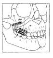
- FIG. 1is a perspective view of an embodiment of the present orthopedic system adapted for use on the maxilla, illustrating a distractor attached to the maxilla and zygoma.
- FIG. 2is a perspective view of a distractor of the system as illustrated in FIG. 1 ;
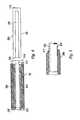
- FIGS. 3 a and 3 bare side views of the distraction assembly of the distractor illustrated in FIG. 2 , in partial section and partial elevation view, showing the distractor at various stages of advancement;
- FIG. 4is a top plan view of the inner sleeve and the outer sleeve of the distractor illustrated in FIG. 2 ;
- FIG. 5is a sectional side view of the inner sleeve and the outer sleeve of FIG. 4 interacting with each other;
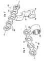
- FIG. 6is a perspective view of the proximal footplate illustrated in FIG. 2 ;
- FIG. 7is a perspective view of the distal footplate illustrated in FIG. 2 ;
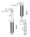
- FIGS. 8 a to 8 eare side views showing the successive steps in the assembly of the device illustrated in FIG. 2 ;
- FIGS. 9 a and 9 bare side and front views, respectively, of the system as illustrated in FIG. 2 , when used in an alternative method of treatment;
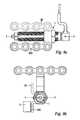
- FIG. 10is an exploded perspective view of an embodiment of the present orthopedic system, illustrating a compact intra-oral distractor for attachment to the maxilla and zygoma;
- FIGS. 11 a and 11 bare side elevation and front elevation views, respectively, of the system illustrated in FIG. 10 ;
- FIGS. 12 a and 12 bare front and side sectional views, respectively of the proximal and distal footplate actuator connecting portions.
- FIG. 13is a side sectional view of the lead screw and the outer sleeve of a distractor of the system illustrated in FIG. 10 ;
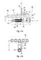
- FIGS. 14 a and 14 bare end sectional views of two embodiments of outer sleeve and distal footplate combinations of a distractor of FIG. 10 showing corresponding profiles used to rotationally lock the pieces together;
- FIGS. 15 a and 15 bare an exploded perspective and a side elevation view of an actuation adapter for use with the system of FIG. 10 .
- the orthopedic device of the present inventionis discussed herein with reference to a preferred embodiment adapted to be used in a linear distraction of the maxilla from the zygoma.
- the orthopedic system 10generally consists of distraction assembly 11 and anchors in the form of proximal and distal bone plates 500 and 700 , respectively.
- the distraction assembly 11has a proximal, or adjustment end 12 and a distal end 13 .
- the orthopedic system 10is affixed to maxilla 21 and zygoma 22 by bone screws 14 which are inserted though screw-holes 15 in footplates 500 and 700 .
- the entire orthopedic system 10is implanted so that the distal bone plate 700 is attached to the zygoma 22 and the proximal bone plate 500 is attached to the maxilla 21 , with the distraction assembly 11 nestled within the buccal sulcus.
- proximalis used to refer to the end of the device associated with the proximal end of the distraction assembly 12 that extends outwards away from the patient's zygoma 22 .
- distalis used to refer to the other end of the device 13 .
- the distraction assembly 11generally consists of a lead screw 100 , an inner sleeve 200 , and an outer sleeve 300 .
- lead screw 100is journaled within outer sleeve 300 , such that screw 100 can rotate, but not translate linearly (axially), relative to outer sleeve 300 .
- Inner sleeve 200has internal threading 202 which interacts with the external threading 104 on screw 100 .
- the interaction of the inner and outer sleeves, as discussed below,is such that they can translate linearly with respect to each other, but cannot rotate relative to each other.
- Lead screw 100has a distal shaft portion 102 provided with external screw threading 104 , an enlarged-diameter intermediate portion 106 , a proximal shaft portion 108 , and a proximal, or adjustment end 110 .
- Adjustment end 110is provided with a tool interface 112 , such as a hexagonal surface that can be driven by a standard hexagonal driving tool.
- Inner sleeve 200is provided with internal threading 202 along at least part of its length.
- the internal threadingmatches the external threading 104 on screw 100 .
- the inner sleeve 200has an exterior surface 204 which is generally smooth except for longitudinal slot 206 (shown in FIG. 4 ) which extends from the proximal end 208 of the sleeve towards the distal end 210 .
- the outer sleeve 300has two different inside cavity portions.
- the proximal cavity portion 302has an inside diameter sized so as to (rotatably) slidably accept the proximal shaft portion 108 of the screw 100 .
- the distal cavity portion 304has an inside diameter sized so as to (axially) slidably accept the inner sleeve 200 .
- the external surface of the outer sleeve 306is preferably threaded along most of its length except for the distal end 310 .
- a mechanismis provided to prevent rotation but allow translation of the inner sleeve 200 in relation to the outer sleeve 300 .
- thisis accomplished by having a portion of the distal end of the outer sleeve 310 formed into a “key” 312 which is sized to fit the longitudinal slot 206 of inner sleeve 200 .
- Thiscan be accomplished by crimping the distal end by application of a force, by an appropriately-shaped tool, sufficient to permanently deform a portion of the distal end.
- a pincould be fixed in a though hole in the wall of the distal end, flush with the outer surface and extending radially inward, the inner end fitting in the longitudinal slot 206 .
- Lead screw 100is journaled within the outer sleeve 300 , so as to allow rotation of the lead screw 100 in relation to outer sleeve 300 but preventing translational motion.
- the journalingis accomplished according to the following.
- the proximal shaft portion 108 of lead screw 100is slidably received within the proximal cavity portion 302 of the outer sleeve 300 , such that screw 100 is free to rotate relative to the outer sleeve 300 .
- a region of the proximal shaft portion 108 , and the adjustment end 110 of screw 100extend out from the proximal end 308 of the sleeve.
- a collar 400is attached to the screw on the extending region of the proximal shaft portion, for example, by inserting pin 402 through matching holes 406 and 114 in the collar and proximal shaft portion, respectively.
- the collar 400 and the enlarged-diameter intermediate shaft portion 106“sandwich” the proximal end 308 of outer sleeve 300 , thereby preventing axial translation of the screw 100 relative to outer sleeve 300 . In this way, screw 100 is effectively journaled within the outer sleeve 300 .
- the collar 400also has a marking, such as an indentation, that acts as a visual reference mark 404 . Since the collar rotates in conjunction with the advancement screw, the reference mark 404 gives the user of the device an easily usable visual means to measure the amount of rotation that the lead screw undergoes when it is adjusted. Knowing the thread pitch of the device, the user can easily convert angular displacement of the mark into linear advancement of the device. Other visual marking methods can be used, including the imprinting of marks on the surface of the collar.
- FIG. 5illustrates how key 312 of the outer sleeve interacts with the longitudinal slot 206 to form a keyway. It will be appreciated that the interaction of longitudinal slot 206 and key 312 form a keyway which prevents relative rotation of the sleeves about the longitudinal axis X—X of the device (designated X—X in FIG. 3 a ), while freely permitting sliding, telescoping movement of the inner sleeve 200 relative to the outer sleeve 300 .
- the systemprovides a mechanism whereby the distractor is anchored or affixed to the patient, for example, by proximal and distal footplates 500 and 700 , which are best understood by reference to FIG. 2 .
- the footplatesare provided with screw holes 15 to accept the bone screws 14 (shown in FIG. 1 ) which affix the device to the bone on either side of the patient's bone repair site. These holes are preferably countersunk to reduce the height of projection of the screw heads above the footplate surface after the device is fully implanted.
- the footplateshave bottom coupling surfaces 506 (shown in FIG. 6 ) and 710 (shown in FIG. 7 ) which may be flat or preferably may be shaped to conform to the contours of the bone to which it is being attached. As discussed in detail below, the coupling surfaces are bone-contacting surfaces when the footplates are attached directly to the patient's bone, or may be construct-contacting surfaces when the footplate is attached to a construct which is in turn mechanically coupled to the patient's
- Footplates 500 and 700serve as the anchors, and can be made from any biocompatible material such as metal, plastic, or composites.
- the footplatesmay be made of titanium or titanium alloy.
- the choice of material from which to construct the footplatesis a routine design matter which depends purely on the particular medical application in which the system according to this invention is used.
- the footplatesare bone plates made of stainless steel. Experiments have shown that stainless steel provides the necessary strength while at the same time being malleable enough to (i) allow for adjustments to the footplates by bending them, and (ii) withstand the cyclic loading inherent in the jaw area.
- the proximal footplate 500has a device-connecting portion 502 comprising an internally-threaded bore 504 which accepts the threading on the external surface 306 of the outer sleeve 300 .
- the internally-threaded bore 504 of the proximal footplateinteracts with the external surface 306 of outer sleeve 300 , so that the orientation and separation of the two footplates in relation to each other can be modified as needed, by screwing the sleeve 300 into the bore 504 .
- proximal footplate 500is locked into position by tightening locking nut 600 (shown in FIG. 2 ) against it, providing sufficient frictional force to keep the footplate in place.
- the distal footplate 700has a device-connecting portion 702 comprising a bore 704 with a diameter that will accept inner sleeve 200 .
- the distal footplateis attached to the distal end of inner sleeve 210 , for example, by pressing the two together, and inserting a pin 706 through holes 708 and 212 .
- the proximal footplate 500is oriented so that line P—P is generally parallel to axis X—X of the distraction assembly 11 . It is also offset above and to either side of the distraction assembly 11 , depending on which side of the patient the assembly is to be implanted. When placed on the right side of the patient, the footplate 500 is offset to the left of the distraction assembly 11 , and vice-versa.
- FIG. 2shows the right-side orientation of the footplate, while FIG. 6 shows the left-side orientation.
- the distal footplate 700is oriented so that line D—D is generally orthogonal to and above axis X—X of the distraction assembly 11 .
- footplates 500 and 700has been found to provide a good combination of accessibility to the screws and holding strength when the device of the present invention is used in the distraction of the maxilla.
- the precise location of the screw holes and the contoured shape and orientation of plates 500 and 700 as seen in FIGS. 2 , 6 , and 7are not a critical aspect of the invention; other screw hole placements, plate shapes, and plate orientations could be used without departing from the spirit and scope of the present invention.
- FIGS. 8 a through 8 eThe assembly of the orthopedic system is best understood by reference to FIGS. 8 a through 8 e .
- the lead screw 100is first inserted into the outer sleeve 300 , as shown in FIG. 8 a .
- the collar 400is then installed on the region of the proximal shaft portion 108 which extends out from the proximal end 308 of the outer sleeve 300 , as shown in FIG. 8 b .
- the collar 400is captivated on the shaft by pressing pin 402 though matching holes in the collar 406 and proximal shaft portion 114 .
- the distal footplate 700is pressed onto the distal end 210 of inner sleeve 200 , as shown in FIG.
- the device of the present inventionis normally used in pairs, one for each side of the patient's face.
- the surgeonmakes an incision, fits the devices to the patient, temporarily removes the devices in order to perform a LeFort I osteotomy (the separation of the maxilla from the rest of the midface), attaches the devices, performs distraction and consolidation, then permanently removes the devices.
- LeFort I osteotomythe separation of the maxilla from the rest of the midface
- a maxillary vestibular incisionis made on the side of the patient's mouth, so that the periosteum can be elevated to expose the maxillary and zygomatic bone.
- the assembled deviceis placed in the proper location and checked for the proper fit.
- the footplatesare generally pre-shaped to be oriented in the proper manner, adjustments can be made to the footplates by bending them, for example, with a set of pliers.
- the distal footplateis then fastened to the zygoma with bone screws 14 , using a number sufficient to provide the necessary stability and strength.
- the screwsare self-tapping, so no pre-tapping of the bone is required. If needed, excess material in the footplate can be removed. For example, if not all of the screw holes need to be used, the portion of the footplate having the unused holes may be clipped off.
- the anterior footplateis then attached in the same manner. The same procedure is then repeated on the other side of the patient.
- the devicesare removed, the osteotomy is performed, and the devices are put back into place.
- the incisionis then closed, leaving the distraction assemblies exposed, but within the patient's mouth.
- the distraction osteogenesis procedureis performed by turning the lead screws on each device using the tool interface 112 .
- FIG. 1which does not illustrate soft tissue
- the reference mark 404can be used to measure the changes in advancement precisely. Generally, distraction progresses at a rate of 1-2 mm per day until full advancement is achieved.
- the advancement phaseis followed by a consolidation phase, with a duration of at least twice as long as that of the advancement phase.
- the devicesare then removed in a separate surgical procedure.
- the proximal footplates 500 of the devicesare not attached to the patient's maxilla 21 , but rather to a construct, such as a dental splint, which is attached to the maxilla 21 .
- a typical dental splintmay consist of a disk of acrylic fitted or wired to the patient's teeth.
- this alternative method of treatmentis the same as that used in the normal course of treatment.
- This embodimentcan be used when the maxilla 21 of the patient cannot support the bone screws 14 used to support the footplates 500 . This is often the case with cleft-lip or -palate patients, who often have large voids in the maxilla 21 where bone should be present. It may also be the preferred embodiment for treating younger patients, due to the presence of un-erupted tooth buds which might be damaged by bone screws 14 .
- the device footplatesmay be attached directly to the patient's bone. Alternatively, they may be attached to one or more constructs, which constructs are attached to the patient's bone. Indeed, the constructs do not necessarily need to be directly attached to the patient's zygoma or maxilla, but rather may be attached to the patient's teeth. What is important is that the device is mechanically coupled to the zygoma and the maxilla with sufficient rigidity in order to reliably perform the distraction. Alternately, the device may be implanted using circummaxillary wiring, in which wire is passed around the bony structure of the maxilla, to provide a firm anchorage for the device.
- FIGS. 9 a and 9 bshows the device as it would be implanted on the left side of a patient using this embodiment.
- the orientation of the proximal footplates 500is mirrored from its normal orientation 30 about the horizontal plane denoted by Y—Y. That is, for the device used on the left side of the patient, the footplate 500 is positioned below and to the right of the distraction assembly 11 , as seen in FIGS. 9 a and 9 b . In practice, this may be done by simply rotating the footplate 500 one hundred eighty degrees (180°) about the X—X axis (as described in FIG. 3 a ), and switching the side of the patient's face to which the device is implanted.
- the footplate 500 used on the right side of the patient when attaching the device directly to the maxilla 21is the same one used on the left side when attaching the device to a dental splint, and vice-versa.
- This a orientationis preferred for the dental splint method because it places the footplate and screw holes closer to the horizontal plane created by the chewing surfaces of the teeth, which is the preferred position for attachment of the footplate to a dental splint.
- FIG. 9 bshows a portion of the splint 3 in relation to the footplate 500 .
- the footplates and/or bone screwsmay be made from a bioresorbable material, and are detachable from the distraction assembly. This allows easy shaping of the footplates (when heated prior to insertion, for example by soaking in hot water). After distraction and consolidation have been completed, the bioresorbable footplates are detached from the distraction assembly and the incisions are closed, leaving the footplates and bone screws in place, to eventually be absorbed into the body. This provides the advantage of not having to perform a second surgical procedure to access the screws to remove the footplates. By reducing the number of surgical procedures required, the unavoidable risk and possible complications associated with any surgery is reduced.
- the bone screwsshould be made of a material that takes at least as long to absorb as the material the footplates are made of, thus ensuring that the footplates are secured until absorbed fully by the body.
- FIGS. 10 , 11 a and 11 billustrate an alternative embodiment of a compact maxillary distractor in which activation of the device results in no overall change in the length “A” of the device 1000 .
- the device 1000 of this embodimentgenerally comprises proximal and distal footplates 800 , 900 connected by an actuator 1100 having a longitudinal axis “X—X.”
- the proximal footplate 800connects to the patient's maxilla 21
- the distal footplate 900connects to the patient's zygoma 22 .
- Bone screws or other suitable fastenersmay be used to fix the footplates to the respective bone segments.
- the proximal footplate 800has a bone attachment portion 802 and an actuator engagement portion 810 .
- the bone attachment portion 802comprises at least one screw hole 804 , and preferably multiple screw holes 804 , suitable for the insertion of a bone screw or similar fastening device.
- the at least one screw hole 804may be countersunk to reduce the height of projection of the screw head above the footplate surface after the device is implanted.
- the proximal footplate bone attachment portion 802further has a bone contacting surface 806 that defines a plane “PP—PP” which is oriented substantially parallel to the patient's sagittal plane, and to the longitudinal axis “X—X” of the actuator 1100 .
- the actuator engagement portion 810comprises a threaded bore 812 configured to engage corresponding external threads 1306 of the actuator lead screw 1300 .
- the bone attachment and actuator engagement portions 802 , 810are joined by an outer sleeve-engaging portion 814 which comprises a reduced thickness, or “necked,” region 816 , configured to be received within a longitudinal slot 1210 in the actuator outer sleeve 1200 .
- the distal footplate 900has a bone attachment portion 902 and an actuator engagement portion 910 .
- the bone attachment portion 902comprises at least one screw hole 904 , and preferably multiple screw holes 940 , suitable for the insertion of a bone screw or similar fastening device.
- the at least one screw hole 904may be countersunk to reduce the height of projection of the screw head above the footplate surface after the device is implanted.
- the distal footplate bone attachment portion 902further has a bone contacting surface 906 that defines a plane “DP—DP” which is oriented substantially perpendicular to the patient's sagittal plane “SP—SP,” to the proximal footplate bone contacting surface plane “PP—PP” and to the longitudinal axis “X—X” of the actuator 1100 .
- the distal footplate actuator engagement portion 910comprises a bore 912 configured to engage the distal end 1206 of the actuator outer sleeve 1200 .
- the actuator assembly 1100comprises a lead screw 1300 and an outer sleeve 1200 , connected in a manner similar to that described for the actuator illustrated in FIGS. 1-9 .
- the lead screw 1300is journaled within the outer sleeve 1200 so that the screw can rotate, but not translate axially relative to the outer sleeve.
- the lead screw 1300has proximal and distal ends 1302 , 1304 , and a length “SL.”
- a portion of the lead screw outer surfacecomprises external threads 1306 configured to engage the internally threaded bore 812 of the proximal footplate actuator attachment portion 810 .
- the lead screw proximal end 1302is unthreaded, and has a transverse hole 1308 suitable for the insertion of a pin 1310 .
- An increased diameter portion 1312is spaced a distance away from the hole 1308 , such that the hole 1308 is located between the increased diameter portion 1312 and the proximal end 1302 of the lead screw 1300 .
- the outer sleeve 1200has proximal and distal ends 1204 , 1206 , with an internal cavity defined by outer sleeve proximal and distal end bores 1211 , 1208 that may encompass the entire length “SL” of the lead screw 1300 , with the exception of the proximal end 1302 .
- the outer sleeve proximal end 1204comprises a bore 1211 sized to allow the lead screw proximal end 1302 to extend therethrough when the lead screw proximal end 1302 is completely inserted into the distal end 1206 of the outer sleeve 1200 .
- the outer sleeve proximal end bore 1211is sized to be smaller than the increased diameter portion of the lead screw 1312 , so that when the lead screw 1300 is fully inserted into the outer sleeve 1200 , the lead screw proximal end 1302 may extend out from the bore 1211 in the outer sleeve proximal end 1204 .
- a hex cap 1314may be placed over the portion of the lead screw proximal end 1302 that extends beyond the outer sleeve proximal end 1204 , and the cap and lead screw may be pinned together with a pin 1310 or dowel inserted through corresponding holes in the two pieces 1315 , 1308 .
- the hex cap 1314is sized to be larger than the outer sleeve proximal end bore 1211 , so that upon pinning, the lead screw proximal end 1302 may not retract into the outer sleeve.
- the outer sleeve proximal end bore 1211is axially captured between the increased diameter portion of the lead screw 1312 and the hex cap 1314 .
- This arrangementprevents axial movement of the lead screw 1300 with respect to the outer sleeve 1200 , but permits relative rotational movement between the two.
- the distal footplate actuator engagement portion 910comprises a bore 912 configured to engage the outside surface 1202 of the distal end 1206 of the outer sleeve 1200 .
- the bore 912may slide onto a portion of the outer sleeve distal end 1206 .
- the outer surface 1202 of the outer sleeve distal end 1206may have a keyed profile, and the bore 912 of distal footplate actuator engaging portion 910 may have a corresponding keyway profile, so that when the footplate bore 912 is slid onto the outer sleeve distal end 1206 , the corresponding surface profiles engage to prevent rotational movement of the footplate 900 and outer sleeve 1200 with respect to each other.
- the outer sleeve distal end surface 1202has a circular profile with at least one flat portion 1212 and the distal footplate bore 912 has a corresponding circular profile with at least one flat portion 913 , so that when the sleeve distal end 1206 is slid onto the footplate bore 912 the flat portions 1212 , 913 correspond, thereby preventing rotation of the footplate 900 and outer sleeve 1200 with respect to each other.
- the outer sleeve distal end surface 1202may have a circular profile with two diametrically opposed flat portions 1213 , 1214 (i.e.
- the distal footplate bore 912may have a corresponding internal profile with a single or two flat portions 915 , 919 .
- any other keyed profile known in the arte.g. corresponding slots, tabs, grooves, etc.
- other arrangements known to those of ordinary skill in the art which actually pin the inner sleeve within the outer sleeveare also contemplated.
- the distal footplate actuator attachment portion bore 912may have a center axis “B—B” (shown if FIG. 11 a ) that is substantially coincident with the actuator longitudinal axis “X—X.”
- the bore 912further may be configured to accept the body 916 of an appropriately sized machine screw 914 such that the screw 914 may be freely inserted in the bore 912 so the distal footplate is axially restrained by the interaction of the bore 912 and the screw head 918 .
- the outer sleeve distal end 1206 bore 1208may comprise threads sized to engage the threaded body of the machine screw 916 , so that, when the distal footplate 900 and the outer sleeve distal end 1206 are fit together, and the machine screw 914 is inserted through the distal footplate bore 912 , tightening of the screw 914 may serve to axially fix the footplate 900 and outer sleeve 1200 together.
- the actuator outer sleeve 1200may further comprise a slot 1210 having a longitudinal axis which is substantially coexistent with the longitudinal axis of the actuator X—X.
- the slot 1210is configured to slidingly receive the proximal footplate outer sleeve-engaging portion 814 when the proximal footplate 800 is threaded onto the lead screw 1300 .
- the interaction between the slot 1210 and the sleeve-engaging portion 814prevents the proximal footplate 800 from rotating with the lead screw 1300 when the device 1000 is actuated, thus forcing the proximal footplate 800 to translate along the lead screw 1300 .
- the slot/footplate interactionalso prevents the proximal and distal footplates 800 , 900 from twisting with respect to each other during actuation.
- the lead screw proximal end 1302is introduced into the outer sleeve distal end 1206 , and the lead screw 1300 is fully inserted into the outer sleeve 1200 so that the lead screw proximal end 1302 extends through the bore 1211 in the proximal end of the outer sleeve 1204 .
- the hex cap 1314is then installed over the lead screw proximal end 1302 and the pin 1310 is inserted to fix the two.
- the proximal footplate threaded bore 812is aligned with the lead screw threads 1306
- the proximal footplate outer sleeve-engaging portion 814is aligned with the outer sleeve slot 1210 .
- Hand rotation of the hex cap 1314then causes the lead screw 1300 to engage the proximal footplate threaded bore 812 , drawing the proximal footplate 800 onto the lead screw 1300 so that the outer sleeve-engaging portion 814 engages the slot 1210 in the outer sleeve 1200 .
- the hex cap 1314is preferably rotated an amount sufficient to draw the proximal footplate actuator attachment portion 810 far enough into the outer sleeve distal end 1206 so that the attachment portion does not interfere with subsequent installation of the distal footplate machine screw 914 .
- the distal footplate bore 912is then aligned to correspond with outer surface 1202 of the outer sleeve distal end 1206 , and the footplate 900 is slid onto the outer sleeve 1200 .
- the machine screw 914is then installed so its threads 916 engage the internally threaded bore 1208 of the outer sleeve distal end 1206 .
- the machine screwis then tightened to fix the distal footplate 900 and the actuator 1100 tightly together.
- the machine screw 914may comprise a bore 920 sized to accept the distal end 1304 of the lead screw 1300 , so that when the distal footplate 900 is installed on the actuation assembly 1100 , and the machine screw 914 is installed, the lead screw distal end 1304 may fit at least partially within the machine screw bore 920 .
- This arrangementallows for maximum thread engagement between the machine screw 914 and the outer sleeve 1200 while maintaining the overall length “A” of the device as small as possible.
- the easy interconnectivity of the elements of the device of this embodimentallows a surgeon to select from several actuator lengths and several footplate sizes so as to customize the device to fit the specific anatomical proportions of an individual patient.
- the actuator 1100 and footplates 800 , 900are removably engageable so that the appropriately sized pieces may be selected by the surgeon at any time prior to installation of the device in the patient.
- the piecesare interchangeable simply by unthreading the appropriate connection (e.g. the proximal footplate threaded bore 812 from the lead screw 1300 , or the distal footplate machine screw 914 from the outer sleeve internally threaded bore 1208 ), then rebuilding the device using the desired piece or pieces.
- the device of the current embodimentis installed at the osteotomy site (see FIG. 1 ) the same as the device of FIG. 2 .
- the proximal footplate 800is attached to the patient's maxilla 21 and the distal footplate 900 is attached to the zygoma 22 .
- rotation of the hex cap 1314 in the appropriate directioncauses the lead screw 1300 to turn, which in turn causes the proximal footplate 800 to translate along the lead screw 1300 in the direction away from the distal footplate 900 .
- the outer sleeve-engagement portion 814slides within the slot 1210 in the outer sleeve 1200 .
- a desired separation of the maxilla 21 and zygoma 22is thereby established.
- Actuation of the distractor of this embodimentresults in no overall change in the length “A” of the device 1000 because separation of the footplates 800 , 900 is achieved merely by the change in position of the proximal footplate 800 along the fixed length of the lead screw 1300 .
- the device of FIG. 10may, in one embodiment, have a posterior footplate bone attachment portion 902 that is offset from the actuator engaging portion 910 , thereby facilitating placement of the actuator 1100 farther back in the mouth compared to devices having no footplate offset.
- a distal footplate having such an offset configurationshown in FIGS. 10 and 11 a , allows placement of at least a portion of the actuator 1100 under the zygoma 22 . This placement reduces the amount of space taken up by the device in the patient's mouth, and also facilitates the installation of longer actuator elements in patients whose anatomy or condition requires using a larger distraction vector.
- the distal footplate offsetallows the use of an actuator 1100 capable of producing a distraction vector that is in a range of from between about 10 mm to about 25 mm.
- the distal footplate 900 of this embodimentcomprises an actuator engagement portion 910 and a bone attachment portion 902 .
- the bone attachment and actuator engagement portions 902 , 910are joined by a substantially horizontal intermediate portion 909 having a longitudinal axis “O—O” that is oriented substantially parallel to the longitudinal axis X—X of the actuator 1100 .
- the bone attachment portion 902has a bone contacting surface 906 that forms a plane which, as in the earlier described embodiments, is substantially perpendicular to the longitudinal axis “X—X” of the device 1000 .
- the offset in the distal footplate attributable to the horizontal intermediate portion 909causes the actuator engagement portion 910 to lie outside of the plane created by the footplate bone contacting surface 906 . It also causes the bone attachment portion 902 to be located closer to the proximal end of the device 1000 than the actuator engagement portion 910 .
- the intermediate portion 909is sized so that the distance “C” between the distal end 911 of the distal footplate actuator engaging portion 910 and the distal footplate bone contacting surface 906 is in a range from between about 1 mm to about 25 mm; more preferably this range is from between about 7 mm to about 12 mm, depending on the size of the patient in whom the device will be installed.
- the vertical distance “B” between the actuator longitudinal axis “X—X” and the distal footplate screw holes 904is in a range from between about 5 mm to about 35 mm; more preferably this range is from between about 16.5 mm to about 26.5 mm.
- the vertical distance “D” between the actuator longitudinal axis “X—,” and the proximal footplate screw holes 804is in a range from between 0 mm to about 20 mm; more preferably, this range is from between 6 mm to about 14 mm.
- the horizontal length “A” of the device 1000is in a range from between 26 mm to about 43 mm.
- intermediate portion 909comprises a substantially horizontal geometry
- the intermediate portion 909may embrace various other geometries (e.g. angled, curved, stepped, etc.) to provide the desired offset between the bone attachment and actuator engagement portions 902 , 910 .
- the proximal and distal footplates 800 , 900may be made of any biocompatible metal (e.g. titanium), plastic or composites.
- the footplatesalso may be made of a bioresorbable material.
- the bone screws used to attach the footplates to the patient's bonemay also be made of bioresorbable material.
- the bone screwsshould be made of a material that takes at least as long to absorb as the footplate material, thus ensuring that the footplates are secured until absorbed fully by the body.
- the proximal and distal footplates 800 , 900may also be formable, to allow the surgeon to shape them to conform to the unique anatomy of the patient's bone.
- the device of the present embodimentneed not be attached directly to the patient's maxilla 21 , but instead may be attached to a construct, such as a dental splint, which is attached to the maxilla 21 .
- a dental splintmay consist of a disk of acrylic fitted or wired to the patient's teeth and can be used when the maxilla 21 of the patient cannot support the bone screws used to support the footplate 800 .
- FIGS. 15 a , 15 bshow an adapter 1400 which may be used to extend the device actuation point (e.g. the hex cap 1314 ) forward to allow easy access with a tool such as a screwdriver.
- Such an adapter 1400may have a proximal end 1402 comprising a hex or other similar tool head 1404 , a distal end 1406 comprising a hex socket 1410 configured to engage hex cap 1314 , and an intermediate universal joint 1408 configured to transmit a rotational input from the tool head 1404 to the hex socket 1410 while accommodating varying angles between the ends 1402 , 1406 .
- the adapter 1400may be configured for permanent attachment to the device hex cap 1314 , and as such would reside within the patient's mouth during the length of the distraction procedure.
- the adapter 1400may be configured for temporary attachment to the hex cap 1314 , and as such would be installed and used during the actual actuation process only.
- the adapterlikewise may consist of various other temporary or permanent arrangements, for example the actuator may comprise a flexible rod attachment, or it could be a rigid adapter. It will be obvious that any kind of extension device known in the art may be used as appropriate to facilitate movement of the actuation point as far forward in the patient's mouth as practical for operation and to suit the comfort of the patient.
- the device of FIGS. 10-14may be installed in a patient, actuated and removed using the same method as described previously with regard to the embodiments illustrated in FIGS. 1-9 .
- actuation of the devicemay include the step of installing a universal or other type adapter which temporarily or permanently relocates the actuation point of the device
- the outer sleevemay be configured to accept a temporary alignment element for use in assuring proper fit and alignment of the device in a patient prior to final installation.
- the outer sleeve 1200may incorporate external threads 1216 configured to engage corresponding internal threads of a temporary alignment element.
- the alignment elementmay comprise a tube or rod having a length, an engagement end having internal threads corresponding to the threads of the outer sleeve 1216 , and a longitudinal axis coincident to the longitudinal axis “X—X” of the device actuator 1100 upon engagement with the outer sleeve.
- the alignment elementshould be long enough to allow a portion of the element to extend out from the patient's mouth when the device is initially fit to the patient. During this initial fitting step, the alignment element allows the surgeon to easily verify or take measurements of the expected distraction vector from outside the patient, prior to final attachment of the device to the maxilla and zygoma 21 , 22 .
- the alignment elementmay also be used by the surgeon as a convenient handle to hold the device during placement.
- the device of the above described embodimentsmay also be provided in the form of a kit.
- the kitmay comprise a plurality of proximal and distal footplates 800 , 900 , as well as a plurality of actuation assembly 1100 .
- the kitmay be provided with proximal footplates 800 having various individual or similar shapes, sizes, number of screw holes, material or other pertinent features.
- the kitmay be provided with distal footplates 900 having various individual or similar shapes, sizes, number of screw holes, material or other pertinent features.
- the plurality of distal footplates 900may each have a different sized intermediate portion 909 so that each distal footplate 900 may provide a different distance “C” between the distal end 911 of the distal footplate actuator engaging portion 910 and the distal footplate bone contacting surface 906 .
- the kitmay be provided with a plurality of actuation assemblies 1100 , each configured to provide a unique distraction length.
- the footplates 800 , 900may attach to the actuation assembly 1100 using easily removable and connectable threaded connections.
- the piecesare interchangeable simply by unthreading the appropriate connection (e.g. the proximal footplate threaded bore 812 from the lead screw 1300 , or the distal footplate machine screw 914 from the outer sleeve internally threaded bore 1208 ), then rebuilding the device using the desired piece or pieces.
- This easy interchangeabilityallows the surgeon to select from a wide variety of footplate sizes and geometries, as well as distraction vector lengths, to build a customized distractor to conform to the individual anatomy of a particular patient.
Landscapes
- Health & Medical Sciences (AREA)
- Orthopedic Medicine & Surgery (AREA)
- Life Sciences & Earth Sciences (AREA)
- Surgery (AREA)
- Medical Informatics (AREA)
- Engineering & Computer Science (AREA)
- Biomedical Technology (AREA)
- Heart & Thoracic Surgery (AREA)
- Nuclear Medicine, Radiotherapy & Molecular Imaging (AREA)
- Molecular Biology (AREA)
- Animal Behavior & Ethology (AREA)
- General Health & Medical Sciences (AREA)
- Public Health (AREA)
- Veterinary Medicine (AREA)
- Surgical Instruments (AREA)
- Orthopedics, Nursing, And Contraception (AREA)
Abstract
Description
Claims (91)
Priority Applications (12)
| Application Number | Priority Date | Filing Date | Title |
|---|---|---|---|
| US10/135,281US6908469B2 (en) | 2000-10-04 | 2002-04-30 | Compact maxillary distractor |
| AT03728593TATE497369T1 (en) | 2002-04-30 | 2003-04-29 | COMPACT JAW BONE DISTRACTION DEVICE |
| MXPA04010743AMXPA04010743A (en) | 2002-04-30 | 2003-04-29 | Compact maxillary distractor. |
| BR0309723-4ABR0309723A (en) | 2002-04-30 | 2003-04-29 | Orthopedic device for separating first and second bone segments, and mounting set for an orthopedic device |
| CA2483583ACA2483583C (en) | 2002-04-30 | 2003-04-29 | Compact maxillary distractor |
| PCT/US2003/013238WO2003092519A1 (en) | 2002-04-30 | 2003-04-29 | Compact maxillary distractor |
| EP10006527AEP2229901A1 (en) | 2002-04-30 | 2003-04-29 | Compact maxillary distractor |
| EP03728593AEP1499250B1 (en) | 2002-04-30 | 2003-04-29 | Compact maxillary distractor |
| JP2004500709AJP4594079B2 (en) | 2002-04-30 | 2003-04-29 | Minimax distractor |
| DE60335944TDE60335944D1 (en) | 2002-04-30 | 2003-04-29 | COMPACT PINK BODY DISTRACTION DEVICE |
| AU2003234280AAU2003234280A1 (en) | 2002-04-30 | 2003-04-29 | Compact maxillary distractor |
| ARP030101526AAR039513A1 (en) | 2002-04-30 | 2003-04-30 | COMPACT MAXILAR DISTRACTOR |
Applications Claiming Priority (3)
| Application Number | Priority Date | Filing Date | Title |
|---|---|---|---|
| US23751900P | 2000-10-04 | 2000-10-04 | |
| US09/971,216US20020040225A1 (en) | 2000-10-04 | 2001-10-03 | Maxillary distractor |
| US10/135,281US6908469B2 (en) | 2000-10-04 | 2002-04-30 | Compact maxillary distractor |
Related Parent Applications (1)
| Application Number | Title | Priority Date | Filing Date |
|---|---|---|---|
| US09/971,216Continuation-In-PartUS20020040225A1 (en) | 2000-10-04 | 2001-10-03 | Maxillary distractor |
Publications (2)
| Publication Number | Publication Date |
|---|---|
| US20020156485A1 US20020156485A1 (en) | 2002-10-24 |
| US6908469B2true US6908469B2 (en) | 2005-06-21 |
Family
ID=29399217
Family Applications (1)
| Application Number | Title | Priority Date | Filing Date |
|---|---|---|---|
| US10/135,281Expired - LifetimeUS6908469B2 (en) | 2000-10-04 | 2002-04-30 | Compact maxillary distractor |
Country Status (11)
| Country | Link |
|---|---|
| US (1) | US6908469B2 (en) |
| EP (2) | EP2229901A1 (en) |
| JP (1) | JP4594079B2 (en) |
| AR (1) | AR039513A1 (en) |
| AT (1) | ATE497369T1 (en) |
| AU (1) | AU2003234280A1 (en) |
| BR (1) | BR0309723A (en) |
| CA (1) | CA2483583C (en) |
| DE (1) | DE60335944D1 (en) |
| MX (1) | MXPA04010743A (en) |
| WO (1) | WO2003092519A1 (en) |
Cited By (29)
| Publication number | Priority date | Publication date | Assignee | Title |
|---|---|---|---|---|
| US20040181229A1 (en)* | 2001-06-04 | 2004-09-16 | Michelson Gary K. | Instrumentation for use with dynamic single-lock anterior cervical plate system having non-detachably fastened and moveable segments |
| US20050021045A1 (en)* | 2001-11-20 | 2005-01-27 | Osteomed L.P. | Facial osteodistraction device |
| US20050027297A1 (en)* | 2001-06-04 | 2005-02-03 | Michelson Gary K. | Dynamic, modular, single-lock anterior cervical plate system having assembleable and moveable segments and instrumentation for installation thereof |
| US20050027298A1 (en)* | 2001-06-06 | 2005-02-03 | Michelson Gary K. | Dynamic, modular, multilock anterior cervical plate system having detachably fastened assembleable and moveable segments and instrumentation for installation thereof |
| US20050085816A1 (en)* | 2001-06-04 | 2005-04-21 | Michelson Gary K. | Method for installation of dynamic anterior cervical plate system having moveable segments |
| US20050187554A1 (en)* | 2001-06-04 | 2005-08-25 | Michelson Gary K. | Method for installation of anterior cervical plate system having vertebral body engaging anchors and connecting plate |
| US20050192576A1 (en)* | 2001-06-06 | 2005-09-01 | Michelson Gary K. | Method for installing dynamic multilock anterior cervical plate system having detachably fastened and moveable segments |
| US20050256526A1 (en)* | 2004-05-13 | 2005-11-17 | Johnston Thomas S | Bone distractor and method |
| US20080039861A1 (en)* | 2001-11-20 | 2008-02-14 | Osteomed L.P. | Method and System for Facial Osteodistraction Using a Cannulated Device |
| US20080243123A1 (en)* | 2007-03-30 | 2008-10-02 | Antonio Jose Gordils Wallis | Maxillary Bone Cutting System, Kit, and Method of Using the Same |
| US20090192514A1 (en)* | 2007-10-09 | 2009-07-30 | Feinberg Stephen E | Implantable distraction osteogenesis device and methods of using same |
| US20100104999A1 (en)* | 2008-10-23 | 2010-04-29 | Bulloch Scott E | Apparatus, System, and Method for Intra-Oral Distraction |
| KR101154612B1 (en) | 2009-10-23 | 2012-06-08 | 지웰전자 주식회사 | Jaw bone distractor |
| US8282635B1 (en) | 2007-01-18 | 2012-10-09 | Amato Cyrus J | Intra-oral devices for craniofacial surgery |
| US20130096559A1 (en)* | 2011-10-18 | 2013-04-18 | Biomet Manufacturing Corp. | Compressive distal humerus plating system |
| WO2013103261A1 (en)* | 2012-01-05 | 2013-07-11 | 주식회사 제일메디칼코퍼레이션 | Bone distractor |
| WO2013162107A1 (en)* | 2012-04-27 | 2013-10-31 | 연세대학교 산학협력단 | Jaw bone expansion system and control method thereof |
| US20130310880A1 (en)* | 2011-04-20 | 2013-11-21 | Ramon L. Ruiz | Distractor device including multiple diameter internal post and related methods |
| US20130325022A1 (en)* | 2012-05-30 | 2013-12-05 | Nick Wright | Laminoplasty System |
| US20160120580A1 (en)* | 2014-11-05 | 2016-05-05 | Thomas S. Johnston, JR. | Detachable actuator arm for distraction devices |
| WO2016149742A1 (en)* | 2015-03-20 | 2016-09-29 | LAMBERT, Leanne Joy | Mandibular reposition device and coupling therefor |
| US9649132B1 (en) | 2015-04-20 | 2017-05-16 | Donald W. Linck | Bone distractor |
| US9700353B2 (en) | 2012-11-27 | 2017-07-11 | Stryker European Holdings I, Llc | Pediatric internal mandibular distractor |
| US9782202B2 (en) | 2012-12-12 | 2017-10-10 | Stryker European Holdings I, Llc | Surgical distance adjusting assembly for a bone distractor |
| US10166053B2 (en) | 2014-12-30 | 2019-01-01 | Stryker European Holdings I, Llc | Distractor with bidirectional rotation control |
| US11471192B2 (en) | 2016-07-14 | 2022-10-18 | Amdt Holdings, Inc. | External bone fixation systems |
| US20220378479A1 (en)* | 2019-12-20 | 2022-12-01 | Small Bone Lengthening Llc | Distraction device with reflector |
| US11553948B2 (en) | 2021-05-20 | 2023-01-17 | University Of Utah Research Foundation | Bone fixation devices, systems, and methods |
| US12213703B2 (en) | 2022-02-23 | 2025-02-04 | DePuy Synthes Products, Inc. | Three dimensional distractors |
Families Citing this family (33)
| Publication number | Priority date | Publication date | Assignee | Title |
|---|---|---|---|---|
| US6972020B1 (en)* | 2001-06-01 | 2005-12-06 | New York University | Multi-directional internal distraction osteogenesis device |
| GB0405386D0 (en)* | 2004-03-10 | 2004-04-21 | Depuy Int Ltd | Device |
| US7182785B2 (en)* | 2004-03-11 | 2007-02-27 | Craniotech Acr Devices, Llc | Mandibular bone transport reconstruction plate |
| JP4980881B2 (en)* | 2004-03-26 | 2012-07-18 | ジンテーズ ゲゼルシャフト ミト ベシュレンクテル ハフツング | Bone screw with joint |
| US7485121B2 (en)* | 2004-05-04 | 2009-02-03 | Synthes (Usa) | Midface distractor |
| US7875033B2 (en)* | 2004-07-19 | 2011-01-25 | Synthes Usa, Llc | Bone distraction apparatus |
| US7901409B2 (en)* | 2006-01-20 | 2011-03-08 | Canaveral Villegas Living Trust | Intramedullar devices and methods to reduce and/or fix damaged bone |
| CN100384383C (en)* | 2006-07-17 | 2008-04-30 | 中国人民解放军第二炮兵总医院 | A medical device for reduction and fixation of inferior orbital wall fracture |
| WO2009053037A2 (en)* | 2007-10-25 | 2009-04-30 | Nobel Biocare Services Ag | Distraction device |
| WO2009091814A1 (en)* | 2008-01-17 | 2009-07-23 | Richard Pober | Dental distractor |
| US20100075270A1 (en)* | 2008-09-19 | 2010-03-25 | Figueroa Alvaro A | Angularly adjustable maxillary distractor and method of distraction |
| WO2011095956A2 (en)* | 2010-02-08 | 2011-08-11 | Rajiv Agarwal | System and methods for bone distraction |
| US9066733B2 (en)* | 2010-04-29 | 2015-06-30 | DePuy Synthes Products, Inc. | Orthognathic implant and methods of use |
| US8764441B2 (en)* | 2010-07-21 | 2014-07-01 | John W. Polley | Method and internal apparatus for determining final position of dentate skeleton in orthognathic surgery |
| KR101154618B1 (en) | 2011-03-16 | 2012-06-08 | 동국대학교 산학협력단 | Mandibular repositioning functional appliance |
| EP2701620A1 (en) | 2011-04-26 | 2014-03-05 | Synthes GmbH | Hinged fixation devices for combined upper jaw correction |
| AU2012202977B2 (en) | 2011-05-23 | 2016-02-11 | Coceancig, Paul Lloyd G. | A distractor device and a method for distracting a jaw bone |
| RU2489982C1 (en)* | 2012-04-02 | 2013-08-20 | федеральное государственное бюджетное учреждение "Центральный научно-исследовательский институт стоматологии и челюстно-лицевой хирургии" Министерства здравоохранения Российской Федерации (ФГБУ "ЦНИИС и ЧЛХ" Минздрава России) | Mini plate for ostesynthesis after multi-segment osteotomy of upper jaw |
| RU2489981C1 (en)* | 2012-04-02 | 2013-08-20 | федеральное государственное бюджетное учреждение "Центральный научно-исследовательский институт стоматологии и челюстно-лицевой хирургии" Министерства здравоохранения Российской Федерации | L-shaped miniplate for osteosynthesis of upper jaw after osteotomy |
| WO2015187123A1 (en)* | 2014-06-02 | 2015-12-10 | Albany Medical College | Dynamic decompressive craniotomy fixation devices and related methods |
| DE102014014096A1 (en)* | 2014-09-23 | 2016-03-24 | Celgen Ag | Distraction implant with improved mechanism |
| US9931138B2 (en)* | 2014-10-15 | 2018-04-03 | Globus Medical, Inc. | Orthopedic extendable rods |
| JP2016174659A (en)* | 2015-03-19 | 2016-10-06 | タキロン株式会社 | Bone fixation plate |
| WO2019104255A1 (en) | 2017-11-24 | 2019-05-31 | Craniofacial Technologies Inc. | Improved maxillary expander and protraction device |
| US10575926B2 (en) | 2017-11-24 | 2020-03-03 | Craniofacial Technologies, Inc. | Maxillary expander |
| US20200405449A1 (en)* | 2018-03-11 | 2020-12-31 | Craniofacial Technologies Inc. | System and method for treating maxillary deficiencies |
| IL260367A (en)* | 2018-07-02 | 2018-08-30 | Osteophile Ltd | Devices, systems and methods for distraction osteogenesis |
| US12226126B2 (en) | 2018-07-13 | 2025-02-18 | Facegenics, Inc. | Cantilever protraction device |
| BR112021003874A2 (en)* | 2018-08-29 | 2021-05-18 | Amdt Holdings, Inc. | adjustable support sets for external fastening systems |
| US11141245B2 (en)* | 2019-02-07 | 2021-10-12 | Dan Rosen | Angled dental implant with angled anchor point |
| CN113180810B (en)* | 2021-04-06 | 2023-04-07 | 四川大学 | Bone fracture plate for zygomatic bone and zygomatic arch incision and internal pushing plastic surgery |
| CN113558794B (en)* | 2021-07-26 | 2022-07-08 | 首都医科大学附属北京口腔医院 | Tooth bone mixed support type external intraoral distraction osteogenesis device and use method |
| CN115317106A (en)* | 2022-07-12 | 2022-11-11 | 中国医学科学院整形外科医院 | An artificial condyle-mandibular extender complex |
Citations (52)
| Publication number | Priority date | Publication date | Assignee | Title |
|---|---|---|---|---|
| US4144643A (en) | 1977-01-19 | 1979-03-20 | Krygier Stanley J | Maxillary orthopedic suture separating orthodontic appliance |
| US4187841A (en) | 1978-07-07 | 1980-02-12 | Knutson Richard A | Bone compression or distraction device |
| US4482318A (en) | 1982-04-08 | 1984-11-13 | Bernhard Forster Gmbh | Orthodontic spreader |
| US4571177A (en) | 1984-02-13 | 1986-02-18 | Rodam Sa | Orthodontic jack for maxillary expansion appliance |
| DE4018273A1 (en) | 1989-07-06 | 1991-01-17 | Schwestka Rainer Dr Med Dent | Surgical operation for correction of jaw malformation - is aided by using models of jaw before and after operation |
| DE4007306C1 (en) | 1990-03-08 | 1991-05-23 | Eska Medical Luebeck Medizintechnik Gmbh & Co, 2400 Luebeck, De | Implant for use in bone surgery - comprises two plates geared to allow relative external adjustment after fixture |
| US5129903A (en) | 1988-06-18 | 1992-07-14 | Luhr Hans Georg | Bone plate |
| US5147358A (en) | 1990-10-23 | 1992-09-15 | Remmler Daniel J | Cranial fixation-distraction and positioning apparatus and method |
| DE4219156A1 (en) | 1992-06-11 | 1993-12-16 | Leibinger Gmbh | Jaw-bone-positioning equipment - has connecting component between bases on bones which can be made rigid or flexible, typically elastic hose filled with hardening plastics material |
| US5314426A (en) | 1992-04-16 | 1994-05-24 | Pohl Anthony P | External bone fixation device |
| US5328364A (en) | 1993-10-15 | 1994-07-12 | Doyle Walter A | Dental clamp |
| US5364396A (en) | 1993-03-29 | 1994-11-15 | Robinson Randolph C | Distraction method and apparatus |
| FR2715291A1 (en) | 1994-01-21 | 1995-07-28 | Allard Michel | Osteosynthesis apparatus for joining two bones or fragments |
| US5540687A (en) | 1993-05-19 | 1996-07-30 | Fairley; Jeffrey D. | Device for the distraction of bones |
| US5616142A (en) | 1994-07-20 | 1997-04-01 | Yuan; Hansen A. | Vertebral auxiliary fixation device |
| EP0770359A1 (en) | 1995-10-05 | 1997-05-02 | Medicon e.G. Chirurgiemechaniker-Genossenschaft | Distraction device for bone segments |
| WO1997020512A1 (en) | 1995-12-01 | 1997-06-12 | Walker David A | Telescopic bone plate for use in bone lenghtening by distraction osteogenesis |
| US5681313A (en) | 1995-02-06 | 1997-10-28 | Karl Leibinger Medizintechnik Gmbh & Co. Kg | Device for the extension of bones |
| DE29716635U1 (en) | 1997-09-16 | 1997-10-30 | Karl Leibinger Medizintechnik GmbH & Co. KG, 78570 Mühlheim | Distraction device for the treatment of bone defects |
| US5700263A (en) | 1996-06-17 | 1997-12-23 | Schendel; Stephen A. | Bone distraction apparatus |
| WO1998009577A1 (en) | 1996-09-04 | 1998-03-12 | Maurice Yves Mommaerts | Apparatus for intraoral distraction osteotomy |
| US5769850A (en) | 1996-10-16 | 1998-06-23 | Chin; Martin | Apparatus and method for submergible, self-retaining distraction osteogenesis |
| US5829971A (en) | 1994-04-04 | 1998-11-03 | Razdolsky; Yan | Osteodistraction device for use in mandibular distraction osteogenesis and a method of making the device |
| DE29813087U1 (en) | 1998-07-22 | 1998-12-24 | Karl Leibinger Medizintechnik GmbH & Co. KG, 78570 Mühlheim | Distraction device |
| WO1999004715A1 (en) | 1997-07-21 | 1999-02-04 | Roger Minoretti | Intraoral distractor for callus distraction in the lower jaw |
| WO1999004713A1 (en) | 1997-07-25 | 1999-02-04 | Eska Implants Gmbh & Co. | Bi-directional retractor set for lower jaw |
| US5873715A (en) | 1998-07-20 | 1999-02-23 | Liou; Eric Jein-Wein | Dental distractor |
| US5885290A (en)* | 1996-12-09 | 1999-03-23 | Guerrero; Cesar A. | Intra-oral bone distraction device |
| US5885283A (en) | 1992-08-04 | 1999-03-23 | Gittleman; Neal B. | Osteogenic mandibular distention apparatus and method |
| US5885289A (en) | 1995-10-14 | 1999-03-23 | Muller; Paul A. | Puller for correcting an upper jaw |
| US5895387A (en) | 1996-10-09 | 1999-04-20 | Romulo Guerrero | Method of craniofacial bone distraction |
| US5906644A (en)* | 1996-08-30 | 1999-05-25 | Powell; Douglas Hunter | Adjustable modular orthopedic implant |
| US5976142A (en) | 1996-10-16 | 1999-11-02 | Chin; Martin | Apparatus and method for distraction osteogenesis of small alveolar bone |
| DE29921046U1 (en) | 1999-11-30 | 2000-05-11 | Karl Leibinger Medizintechnik GmbH & Co. KG, 78570 Mühlheim | Bone distractor |
| WO2000033751A1 (en) | 1998-12-04 | 2000-06-15 | Wittenstein Gmbh & Co Kg | Distraction assembly |
| FR2787698A1 (en) | 1998-10-27 | 2000-06-30 | Obl | INTRAORAL MANDIBULAR DISTRACTOR |
| US6086365A (en) | 1998-02-02 | 2000-07-11 | Walter Lorenz Surgical, Inc. | Bonded intermaxillary fixation splint |
| DE20008797U1 (en) | 2000-05-16 | 2000-08-03 | Karl Leibinger Medizintechnik GmbH & Co. KG, 78570 Mühlheim | Bone distractor |
| DE20008796U1 (en) | 2000-05-16 | 2000-08-03 | Karl Leibinger Medizintechnik GmbH & Co. KG, 78570 Mühlheim | Bone distractor |
| US6106525A (en) | 1997-09-22 | 2000-08-22 | Sachse; Hans | Fully implantable bone expansion device |
| US6113599A (en) | 1997-06-04 | 2000-09-05 | Kalpa Engineering, Inc. | Apparatus for internal mandibular distraction |
| WO2000056235A1 (en) | 1999-03-23 | 2000-09-28 | Synthes Ag Chur | Orthopedic system having detachable bone anchors |
| US6139316A (en) | 1999-01-26 | 2000-10-31 | Sachdeva; Rohit C. L. | Device for bone distraction and tooth movement |
| US6171313B1 (en) | 1998-07-02 | 2001-01-09 | Yan Razdolsky | Distraction apparatus for subapical osteotomy and vertical segment distraction and ridge augmentation |
| DE20012536U1 (en) | 2000-07-19 | 2001-01-11 | Karl Leibinger Medizintechnik GmbH & Co. KG, 78570 Mühlheim | Device for distraction of at least two bone segments |
| US6176859B1 (en) | 1999-02-09 | 2001-01-23 | Paul A. Muller | Pulling apparatus for correcting a jaw |
| US6187004B1 (en) | 1993-07-14 | 2001-02-13 | Jeffrey A. Fearon | Subcutaneous bone expansion device |
| US6217323B1 (en) | 1999-08-18 | 2001-04-17 | Eric Jein-Wein Liou | Dental distractor |
| US6241517B1 (en) | 1998-04-23 | 2001-06-05 | Michael O. Williams | Mandibular and maxillary arch expander |
| WO2001041662A1 (en) | 1999-12-09 | 2001-06-14 | Macropore | Completely resorbable connective tissue distraction devices and techniques |
| US6293947B1 (en) | 2000-01-28 | 2001-09-25 | Daniel Buchbinder | Distraction osteogenesis device and method |
| US6471706B1 (en)* | 2000-04-18 | 2002-10-29 | Walter Lorenz Surgical, Inc. | Resorbable bone distractor and method |
Family Cites Families (3)
| Publication number | Priority date | Publication date | Assignee | Title |
|---|---|---|---|---|
| DE3601715A1 (en)* | 1986-01-22 | 1987-07-23 | Heinl Thomas | SURGICAL INSTRUMENT SET FOR CONNECTING BONE FRAGMENTS |
| IT1298413B1 (en)* | 1997-05-21 | 2000-01-05 | Orthofix Srl | EXTERNAL MINIFIXER DEVICE FOR SMALL BONE TREATMENT |
| AR033840A1 (en)* | 2000-10-04 | 2004-01-07 | Synthes Ag | AN ORTHOPEDIC DEVICE TO MODIFY THE DISTANCE BETWEEN THE MAXILAR AND THE CIGOMA OF A PATIENT |
- 2002
- 2002-04-30USUS10/135,281patent/US6908469B2/ennot_activeExpired - Lifetime
- 2003
- 2003-04-29ATAT03728593Tpatent/ATE497369T1/ennot_activeIP Right Cessation
- 2003-04-29AUAU2003234280Apatent/AU2003234280A1/ennot_activeAbandoned
- 2003-04-29CACA2483583Apatent/CA2483583C/ennot_activeExpired - Fee Related
- 2003-04-29BRBR0309723-4Apatent/BR0309723A/ennot_activeIP Right Cessation
- 2003-04-29EPEP10006527Apatent/EP2229901A1/ennot_activeWithdrawn
- 2003-04-29WOPCT/US2003/013238patent/WO2003092519A1/enactiveApplication Filing
- 2003-04-29MXMXPA04010743Apatent/MXPA04010743A/ennot_activeApplication Discontinuation
- 2003-04-29EPEP03728593Apatent/EP1499250B1/ennot_activeExpired - Lifetime
- 2003-04-29JPJP2004500709Apatent/JP4594079B2/ennot_activeExpired - Fee Related
- 2003-04-29DEDE60335944Tpatent/DE60335944D1/ennot_activeExpired - Lifetime
- 2003-04-30ARARP030101526Apatent/AR039513A1/enunknown
Patent Citations (57)
| Publication number | Priority date | Publication date | Assignee | Title |
|---|---|---|---|---|
| US4144643A (en) | 1977-01-19 | 1979-03-20 | Krygier Stanley J | Maxillary orthopedic suture separating orthodontic appliance |
| US4187841A (en) | 1978-07-07 | 1980-02-12 | Knutson Richard A | Bone compression or distraction device |
| US4482318A (en) | 1982-04-08 | 1984-11-13 | Bernhard Forster Gmbh | Orthodontic spreader |
| US4571177A (en) | 1984-02-13 | 1986-02-18 | Rodam Sa | Orthodontic jack for maxillary expansion appliance |
| US5129903A (en) | 1988-06-18 | 1992-07-14 | Luhr Hans Georg | Bone plate |
| DE4018273A1 (en) | 1989-07-06 | 1991-01-17 | Schwestka Rainer Dr Med Dent | Surgical operation for correction of jaw malformation - is aided by using models of jaw before and after operation |
| DE4007306C1 (en) | 1990-03-08 | 1991-05-23 | Eska Medical Luebeck Medizintechnik Gmbh & Co, 2400 Luebeck, De | Implant for use in bone surgery - comprises two plates geared to allow relative external adjustment after fixture |
| US5147358A (en) | 1990-10-23 | 1992-09-15 | Remmler Daniel J | Cranial fixation-distraction and positioning apparatus and method |
| US5314426A (en) | 1992-04-16 | 1994-05-24 | Pohl Anthony P | External bone fixation device |
| DE4219156A1 (en) | 1992-06-11 | 1993-12-16 | Leibinger Gmbh | Jaw-bone-positioning equipment - has connecting component between bases on bones which can be made rigid or flexible, typically elastic hose filled with hardening plastics material |
| US5885283A (en) | 1992-08-04 | 1999-03-23 | Gittleman; Neal B. | Osteogenic mandibular distention apparatus and method |
| US5364396A (en) | 1993-03-29 | 1994-11-15 | Robinson Randolph C | Distraction method and apparatus |
| US5540687A (en) | 1993-05-19 | 1996-07-30 | Fairley; Jeffrey D. | Device for the distraction of bones |
| US6187004B1 (en) | 1993-07-14 | 2001-02-13 | Jeffrey A. Fearon | Subcutaneous bone expansion device |
| US5328364A (en) | 1993-10-15 | 1994-07-12 | Doyle Walter A | Dental clamp |
| FR2715291A1 (en) | 1994-01-21 | 1995-07-28 | Allard Michel | Osteosynthesis apparatus for joining two bones or fragments |
| US5829971A (en) | 1994-04-04 | 1998-11-03 | Razdolsky; Yan | Osteodistraction device for use in mandibular distraction osteogenesis and a method of making the device |
| US5616142A (en) | 1994-07-20 | 1997-04-01 | Yuan; Hansen A. | Vertebral auxiliary fixation device |
| US5681313A (en) | 1995-02-06 | 1997-10-28 | Karl Leibinger Medizintechnik Gmbh & Co. Kg | Device for the extension of bones |
| EP0770359A1 (en) | 1995-10-05 | 1997-05-02 | Medicon e.G. Chirurgiemechaniker-Genossenschaft | Distraction device for bone segments |
| US5855580A (en) | 1995-10-05 | 1999-01-05 | Kreidler; Winfried | Distraction device |
| US5885289A (en) | 1995-10-14 | 1999-03-23 | Muller; Paul A. | Puller for correcting an upper jaw |
| WO1997020512A1 (en) | 1995-12-01 | 1997-06-12 | Walker David A | Telescopic bone plate for use in bone lenghtening by distraction osteogenesis |
| US5902304A (en) | 1995-12-01 | 1999-05-11 | Walker; David A. | Telescopic bone plate for use in bone lengthening by distraction osteogenesis |
| US5700263A (en) | 1996-06-17 | 1997-12-23 | Schendel; Stephen A. | Bone distraction apparatus |
| US5906644A (en)* | 1996-08-30 | 1999-05-25 | Powell; Douglas Hunter | Adjustable modular orthopedic implant |
| WO1998009577A1 (en) | 1996-09-04 | 1998-03-12 | Maurice Yves Mommaerts | Apparatus for intraoral distraction osteotomy |
| US5895387A (en) | 1996-10-09 | 1999-04-20 | Romulo Guerrero | Method of craniofacial bone distraction |
| US5976142A (en) | 1996-10-16 | 1999-11-02 | Chin; Martin | Apparatus and method for distraction osteogenesis of small alveolar bone |
| US5810812A (en) | 1996-10-16 | 1998-09-22 | Chin; Martin | Apparatus and method for submergible self-retaining mandibular distractor |
| US5807382A (en) | 1996-10-16 | 1998-09-15 | Chin; Martin | Apparatus and method for submergible, self-retaining zygoma distractor |
| US5769850A (en) | 1996-10-16 | 1998-06-23 | Chin; Martin | Apparatus and method for submergible, self-retaining distraction osteogenesis |
| US5885290A (en)* | 1996-12-09 | 1999-03-23 | Guerrero; Cesar A. | Intra-oral bone distraction device |
| US6113599A (en) | 1997-06-04 | 2000-09-05 | Kalpa Engineering, Inc. | Apparatus for internal mandibular distraction |
| WO1999004715A1 (en) | 1997-07-21 | 1999-02-04 | Roger Minoretti | Intraoral distractor for callus distraction in the lower jaw |
| WO1999004713A1 (en) | 1997-07-25 | 1999-02-04 | Eska Implants Gmbh & Co. | Bi-directional retractor set for lower jaw |
| DE29716635U1 (en) | 1997-09-16 | 1997-10-30 | Karl Leibinger Medizintechnik GmbH & Co. KG, 78570 Mühlheim | Distraction device for the treatment of bone defects |
| US6106525A (en) | 1997-09-22 | 2000-08-22 | Sachse; Hans | Fully implantable bone expansion device |
| US6086365A (en) | 1998-02-02 | 2000-07-11 | Walter Lorenz Surgical, Inc. | Bonded intermaxillary fixation splint |
| US6241517B1 (en) | 1998-04-23 | 2001-06-05 | Michael O. Williams | Mandibular and maxillary arch expander |
| US6171313B1 (en) | 1998-07-02 | 2001-01-09 | Yan Razdolsky | Distraction apparatus for subapical osteotomy and vertical segment distraction and ridge augmentation |
| US5873715A (en) | 1998-07-20 | 1999-02-23 | Liou; Eric Jein-Wein | Dental distractor |
| DE29813087U1 (en) | 1998-07-22 | 1998-12-24 | Karl Leibinger Medizintechnik GmbH & Co. KG, 78570 Mühlheim | Distraction device |
| FR2787698A1 (en) | 1998-10-27 | 2000-06-30 | Obl | INTRAORAL MANDIBULAR DISTRACTOR |
| WO2000033751A1 (en) | 1998-12-04 | 2000-06-15 | Wittenstein Gmbh & Co Kg | Distraction assembly |
| US6139316A (en) | 1999-01-26 | 2000-10-31 | Sachdeva; Rohit C. L. | Device for bone distraction and tooth movement |
| US6176859B1 (en) | 1999-02-09 | 2001-01-23 | Paul A. Muller | Pulling apparatus for correcting a jaw |
| WO2000056235A1 (en) | 1999-03-23 | 2000-09-28 | Synthes Ag Chur | Orthopedic system having detachable bone anchors |
| US6217323B1 (en) | 1999-08-18 | 2001-04-17 | Eric Jein-Wein Liou | Dental distractor |
| EP1088520A2 (en) | 1999-09-29 | 2001-04-04 | Yan Razdolsky | Distraction apparatus for the maxilla or mandible |
| DE29921046U1 (en) | 1999-11-30 | 2000-05-11 | Karl Leibinger Medizintechnik GmbH & Co. KG, 78570 Mühlheim | Bone distractor |
| WO2001041662A1 (en) | 1999-12-09 | 2001-06-14 | Macropore | Completely resorbable connective tissue distraction devices and techniques |
| US6293947B1 (en) | 2000-01-28 | 2001-09-25 | Daniel Buchbinder | Distraction osteogenesis device and method |
| US6471706B1 (en)* | 2000-04-18 | 2002-10-29 | Walter Lorenz Surgical, Inc. | Resorbable bone distractor and method |
| DE20008796U1 (en) | 2000-05-16 | 2000-08-03 | Karl Leibinger Medizintechnik GmbH & Co. KG, 78570 Mühlheim | Bone distractor |
| DE20008797U1 (en) | 2000-05-16 | 2000-08-03 | Karl Leibinger Medizintechnik GmbH & Co. KG, 78570 Mühlheim | Bone distractor |
| DE20012536U1 (en) | 2000-07-19 | 2001-01-11 | Karl Leibinger Medizintechnik GmbH & Co. KG, 78570 Mühlheim | Device for distraction of at least two bone segments |
Cited By (64)
| Publication number | Priority date | Publication date | Assignee | Title |
|---|---|---|---|---|
| US7547306B2 (en) | 2001-06-04 | 2009-06-16 | Warsaw Orthopedic, Inc. | Method for installation of dynamic, single-lock anterior cervical plate system having non-detachably fastened and moveable segments |
| US20050216010A1 (en)* | 2001-06-04 | 2005-09-29 | Michelson Gary K | Method for installation of dynamic, single-lock anterior cervical plate system having non-detachably fastened and moveable segments |
| US20050027297A1 (en)* | 2001-06-04 | 2005-02-03 | Michelson Gary K. | Dynamic, modular, single-lock anterior cervical plate system having assembleable and moveable segments and instrumentation for installation thereof |
| US7824432B2 (en) | 2001-06-04 | 2010-11-02 | Warsaw Orthopedic, Inc. | Method for installation of dynamic anterior cervical plate system having moveable segments |
| US20050085816A1 (en)* | 2001-06-04 | 2005-04-21 | Michelson Gary K. | Method for installation of dynamic anterior cervical plate system having moveable segments |
| US20050187554A1 (en)* | 2001-06-04 | 2005-08-25 | Michelson Gary K. | Method for installation of anterior cervical plate system having vertebral body engaging anchors and connecting plate |
| US7811285B2 (en)* | 2001-06-04 | 2010-10-12 | Warsaw Orthopedic, Inc. | Dynamic, modular, single-lock anterior cervical plate system having assembleable and moveable segments and instrumentation for installation thereof |
| US20110054528A1 (en)* | 2001-06-04 | 2011-03-03 | Michelson Gary K | Dynamic plate system having moveable segments |
| US8048076B2 (en) | 2001-06-04 | 2011-11-01 | Warsaw Orthopedic, Inc. | Method for installation of anterior cervical plate system having vertebral body engaging anchors and connecting plate |
| US7985224B2 (en) | 2001-06-04 | 2011-07-26 | Warsaw Orthopedic, Inc. | Method for installation of dynamic, single-lock anterior cervical plate system having non-detachably fastened and moveable segments |
| US7740630B2 (en) | 2001-06-04 | 2010-06-22 | Warsaw Orthopedic, Inc. | Anterior cervical plate system having vertebral body engaging anchors and connecting plate |
| US7399301B2 (en) | 2001-06-04 | 2008-07-15 | Warsaw Orthopedic, Inc. | Instrumentation for use with dynamic single-lock anterior cervical plate system having non-detachably fastened and moveable segments |
| US8834533B2 (en) | 2001-06-04 | 2014-09-16 | Warsaw Orthopedic, Inc. | Dynamic plate system having moveable segments |
| US8323283B2 (en) | 2001-06-04 | 2012-12-04 | Warsaw Orthopedic, Inc. | Plate system having bone portion engaging anchors and connecting plate |
| US20040181229A1 (en)* | 2001-06-04 | 2004-09-16 | Michelson Gary K. | Instrumentation for use with dynamic single-lock anterior cervical plate system having non-detachably fastened and moveable segments |
| US20090259226A1 (en)* | 2001-06-04 | 2009-10-15 | Michelson Gary K | Method for installation of dynamic, single-lock anterior cervical plate system having non-detachably fastened and moveable segments |
| US20050216009A1 (en)* | 2001-06-06 | 2005-09-29 | Michelson Gary K | Instrumentation for use with dynamic multilock anterior cervical plate system having non-detachably fastened and moveable segments |
| US7621943B2 (en) | 2001-06-06 | 2009-11-24 | Warsaw Orthopedic, Inc. | Method for installing dynamic multilock anterior cervical plate system having detachably fastened and moveable segments |
| US7704250B2 (en) | 2001-06-06 | 2010-04-27 | Warsaw Orthopedic, Inc. | Instrumentation for use with dynamic multilock anterior cervical plate system having non-detachably fastened and moveable segments |
| US7803157B2 (en)* | 2001-06-06 | 2010-09-28 | Warsaw Orthopedic, Inc. | Dynamic, modular, multilock anterior cervical plate system having detachably fastened assembleable and moveable segments and instrumentation for installation thereof |
| US20050192576A1 (en)* | 2001-06-06 | 2005-09-01 | Michelson Gary K. | Method for installing dynamic multilock anterior cervical plate system having detachably fastened and moveable segments |
| US20050027298A1 (en)* | 2001-06-06 | 2005-02-03 | Michelson Gary K. | Dynamic, modular, multilock anterior cervical plate system having detachably fastened assembleable and moveable segments and instrumentation for installation thereof |
| US7621922B2 (en)* | 2001-11-20 | 2009-11-24 | Osteomed L.P. | Facial osteodistraction device |
| US20050021045A1 (en)* | 2001-11-20 | 2005-01-27 | Osteomed L.P. | Facial osteodistraction device |
| US20080039861A1 (en)* | 2001-11-20 | 2008-02-14 | Osteomed L.P. | Method and System for Facial Osteodistraction Using a Cannulated Device |
| US7892241B2 (en)* | 2001-11-20 | 2011-02-22 | Osteomed, L.P. | Method and system for facial osteodistraction using a cannulated device |
| US7686836B2 (en)* | 2004-05-13 | 2010-03-30 | Kls-Martin, L.P. | Bone distractor and method |
| US20050256526A1 (en)* | 2004-05-13 | 2005-11-17 | Johnston Thomas S | Bone distractor and method |
| US8282635B1 (en) | 2007-01-18 | 2012-10-09 | Amato Cyrus J | Intra-oral devices for craniofacial surgery |
| US8029523B2 (en) | 2007-03-30 | 2011-10-04 | Innovative Implant Technology, Llc | Maxillary bone cutting system, kit, and method of using the same |
| US8308727B2 (en) | 2007-03-30 | 2012-11-13 | Innovative Implant Technology, Llc | Flexible tooling for use in maxillary sinus elevation procedures and method of using the same |
| US20080243123A1 (en)* | 2007-03-30 | 2008-10-02 | Antonio Jose Gordils Wallis | Maxillary Bone Cutting System, Kit, and Method of Using the Same |
| WO2008121555A3 (en)* | 2007-03-30 | 2008-11-27 | Innovative Implant Technology | Maxillary bone cutting system, kit, and method of using the same |
| US20090181343A1 (en)* | 2007-03-30 | 2009-07-16 | Ernesto Hernandez | Flexible tooling for use in maxillary sinus elevation procedures and method of using the same |
| US20090192514A1 (en)* | 2007-10-09 | 2009-07-30 | Feinberg Stephen E | Implantable distraction osteogenesis device and methods of using same |
| US8529579B2 (en) | 2008-10-23 | 2013-09-10 | Intrinsic Medical, Llc | Apparatus, system, and method for intra-oral distraction |
| WO2010048556A3 (en)* | 2008-10-23 | 2010-07-22 | Intrinsic Medical, Llc | Apparatus, system, and method for intra-oral distraction |
| US20100104999A1 (en)* | 2008-10-23 | 2010-04-29 | Bulloch Scott E | Apparatus, System, and Method for Intra-Oral Distraction |
| KR101154612B1 (en) | 2009-10-23 | 2012-06-08 | 지웰전자 주식회사 | Jaw bone distractor |
| US20130310880A1 (en)* | 2011-04-20 | 2013-11-21 | Ramon L. Ruiz | Distractor device including multiple diameter internal post and related methods |
| US10492840B2 (en) | 2011-04-20 | 2019-12-03 | Ramon L. Ruiz | Distractor device including multiple diameter internal post and related methods |
| US9308026B2 (en)* | 2011-04-20 | 2016-04-12 | Ramon L. Ruiz | Distractor device including multiple diameter internal post and related methods |
| US20130096559A1 (en)* | 2011-10-18 | 2013-04-18 | Biomet Manufacturing Corp. | Compressive distal humerus plating system |
| US9320553B2 (en)* | 2011-10-18 | 2016-04-26 | Biomet Manufacturing, Llc | Compressive distal humerus plating system |
| US10828067B2 (en) | 2011-10-18 | 2020-11-10 | Biomet Manufacturing, Llc | Compressive distal humerus plating system |
| WO2013103261A1 (en)* | 2012-01-05 | 2013-07-11 | 주식회사 제일메디칼코퍼레이션 | Bone distractor |
| US9883896B2 (en) | 2012-04-27 | 2018-02-06 | Industry-Academic Cooperation Foundation, Yonsei University | Jawbone distraction system and a control method thereof capable controlling operation using a remote control |
| WO2013162107A1 (en)* | 2012-04-27 | 2013-10-31 | 연세대학교 산학협력단 | Jaw bone expansion system and control method thereof |
| US10709482B2 (en)* | 2012-05-30 | 2020-07-14 | Globus Medical, Inc. | Laminoplasty system |
| US20130325022A1 (en)* | 2012-05-30 | 2013-12-05 | Nick Wright | Laminoplasty System |
| US9700353B2 (en) | 2012-11-27 | 2017-07-11 | Stryker European Holdings I, Llc | Pediatric internal mandibular distractor |
| US9782202B2 (en) | 2012-12-12 | 2017-10-10 | Stryker European Holdings I, Llc | Surgical distance adjusting assembly for a bone distractor |
| US10034697B2 (en)* | 2014-11-05 | 2018-07-31 | Kls-Martin, L.P. | Detachable actuator arm for distraction devices |
| US20160120580A1 (en)* | 2014-11-05 | 2016-05-05 | Thomas S. Johnston, JR. | Detachable actuator arm for distraction devices |
| US10166053B2 (en) | 2014-12-30 | 2019-01-01 | Stryker European Holdings I, Llc | Distractor with bidirectional rotation control |
| WO2016149742A1 (en)* | 2015-03-20 | 2016-09-29 | LAMBERT, Leanne Joy | Mandibular reposition device and coupling therefor |
| US11051910B2 (en) | 2015-03-20 | 2021-07-06 | Geoffrey James Lambert | Mandibular reposition device and coupling therefor |
| US9649132B1 (en) | 2015-04-20 | 2017-05-16 | Donald W. Linck | Bone distractor |
| US11471192B2 (en) | 2016-07-14 | 2022-10-18 | Amdt Holdings, Inc. | External bone fixation systems |
| US11969191B2 (en) | 2016-07-14 | 2024-04-30 | Arthrex, Inc. | External bone fixation struts and systems |
| US12369949B2 (en) | 2016-07-14 | 2025-07-29 | Arthrex, Inc. | External bone fixation struts and systems |
| US20220378479A1 (en)* | 2019-12-20 | 2022-12-01 | Small Bone Lengthening Llc | Distraction device with reflector |
| US11553948B2 (en) | 2021-05-20 | 2023-01-17 | University Of Utah Research Foundation | Bone fixation devices, systems, and methods |
| US12213703B2 (en) | 2022-02-23 | 2025-02-04 | DePuy Synthes Products, Inc. | Three dimensional distractors |
Also Published As
| Publication number | Publication date |
|---|---|
| ATE497369T1 (en) | 2011-02-15 |
| AR039513A1 (en) | 2005-02-23 |
| DE60335944D1 (en) | 2011-03-17 |
| AU2003234280A1 (en) | 2003-11-17 |
| EP1499250A1 (en) | 2005-01-26 |
| CA2483583A1 (en) | 2003-11-13 |
| US20020156485A1 (en) | 2002-10-24 |
| BR0309723A (en) | 2005-02-09 |
| WO2003092519A1 (en) | 2003-11-13 |
| JP2005523765A (en) | 2005-08-11 |
| CA2483583C (en) | 2012-07-03 |
| EP1499250B1 (en) | 2011-02-02 |
| MXPA04010743A (en) | 2005-03-07 |
| EP2229901A1 (en) | 2010-09-22 |
| JP4594079B2 (en) | 2010-12-08 |
Similar Documents
| Publication | Publication Date | Title |
|---|---|---|
| US6908469B2 (en) | Compact maxillary distractor | |
| US10433887B2 (en) | Hinged fixation devices for combined upper jaw correction | |
| US11751911B2 (en) | Intermaxillary fixation device and method of using same | |
| JP4230697B2 (en) | Method and apparatus for pawl adjustment of a bone segment | |
| US5954769A (en) | Surgical drill positioning guide | |
| US5885290A (en) | Intra-oral bone distraction device | |
| CA2424108C (en) | Maxillary distractor | |
| KR102800060B1 (en) | Maxillary expander and protractor | |
| US7347687B2 (en) | Distraction apparatus for orthodontic, orthognathic and oral/maxillofacial surgery applications on the mandible | |
| Levine | AO compression plating technique for treating fractures of the edentulous mandible | |
| HK1055664B (en) | Maxillary distractor | |
| GB2388546A (en) | A fixture for osseodistraction of the alveolar process |
Legal Events
| Date | Code | Title | Description |
|---|---|---|---|
| AS | Assignment | Owner name:SYNTHES (USA), PENNSYLVANIA Free format text:ASSIGNMENT OF ASSIGNORS INTEREST;ASSIGNORS:SELLERS, TIMOTHY M.;NOON, JOHN M.;HAAG, RENE;REEL/FRAME:012858/0354;SIGNING DATES FROM 20020425 TO 20020426 Owner name:SYNTHES AG CHUR, SWITZERLAND Free format text:ASSIGNMENT OF ASSIGNORS INTEREST;ASSIGNORS:SELLERS, TIMOTHY M.;NOON, JOHN M.;HAAG, RENE;REEL/FRAME:012858/0354;SIGNING DATES FROM 20020425 TO 20020426 | |
| STCF | Information on status: patent grant | Free format text:PATENTED CASE | |
| FPAY | Fee payment | Year of fee payment:4 | |
| FEPP | Fee payment procedure | Free format text:PAYER NUMBER DE-ASSIGNED (ORIGINAL EVENT CODE: RMPN); ENTITY STATUS OF PATENT OWNER: LARGE ENTITY Free format text:PAYOR NUMBER ASSIGNED (ORIGINAL EVENT CODE: ASPN); ENTITY STATUS OF PATENT OWNER: LARGE ENTITY | |
| AS | Assignment | Owner name:SYNTHES USA, LLC, PENNSYLVANIA Free format text:CHANGE OF NAME;ASSIGNOR:SYNTHES (U.S.A.);REEL/FRAME:022214/0552 Effective date:20081223 Owner name:SYNTHES USA, LLC,PENNSYLVANIA Free format text:CHANGE OF NAME;ASSIGNOR:SYNTHES (U.S.A.);REEL/FRAME:022214/0552 Effective date:20081223 | |
| FPAY | Fee payment | Year of fee payment:8 | |
| FPAY | Fee payment | Year of fee payment:12 |