US6907534B2 - Minimizing power consumption in pipelined circuit by shutting down pipelined circuit in response to predetermined period of time having expired - Google Patents
Minimizing power consumption in pipelined circuit by shutting down pipelined circuit in response to predetermined period of time having expiredDownload PDFInfo
- Publication number
- US6907534B2 US6907534B2US09/894,142US89414201AUS6907534B2US 6907534 B2US6907534 B2US 6907534B2US 89414201 AUS89414201 AUS 89414201AUS 6907534 B2US6907534 B2US 6907534B2
- Authority
- US
- United States
- Prior art keywords
- circuit
- pipelined
- power
- time
- stage
- Prior art date
- Legal status (The legal status is an assumption and is not a legal conclusion. Google has not performed a legal analysis and makes no representation as to the accuracy of the status listed.)
- Expired - Lifetime, expires
Links
Images


Classifications
- G—PHYSICS
- G06—COMPUTING OR CALCULATING; COUNTING
- G06F—ELECTRIC DIGITAL DATA PROCESSING
- G06F1/00—Details not covered by groups G06F3/00 - G06F13/00 and G06F21/00
- G06F1/26—Power supply means, e.g. regulation thereof
- G06F1/32—Means for saving power
- G06F1/3203—Power management, i.e. event-based initiation of a power-saving mode
- G—PHYSICS
- G06—COMPUTING OR CALCULATING; COUNTING
- G06F—ELECTRIC DIGITAL DATA PROCESSING
- G06F9/00—Arrangements for program control, e.g. control units
- G06F9/06—Arrangements for program control, e.g. control units using stored programs, i.e. using an internal store of processing equipment to receive or retain programs
- G06F9/30—Arrangements for executing machine instructions, e.g. instruction decode
- G06F9/38—Concurrent instruction execution, e.g. pipeline or look ahead
- G06F9/3867—Concurrent instruction execution, e.g. pipeline or look ahead using instruction pipelines
- G06F9/3869—Implementation aspects, e.g. pipeline latches; pipeline synchronisation and clocking
Definitions
- the present inventionis generally related to power management techniques for computer chips. More particularly, the present invention is generally related to reducing power consumption of a pipelined circuit in a computer chip.
- a pipelined circuitIn a typical microprocessor chip, designers often use a pipelined circuit to perform certain operations, such as floating point computations, for increasing the chip's frequency.
- a pipelined circuitconventionally includes multiple pipeline stage circuits for performing the computations.
- Conventional pipeline stage circuitsare often modified to increase the performance of the chip.
- high-performance pipeline stage circuitsoften substantially dissipate power when performing calculations. Even when functioning in an idle or sleep mode, conventional pipeline stage circuits dissipate a significant amount of power through leakage paths.
- an on-chip decoupling capacitanceis enlarged or a dummy cycle is introduced in the pipeline stage circuits to prevent an inductive spike. Enlarging the on-chip decoupling capacitance, however, has not proved feasible for a variant demand for power during chip operation. Also, executing a dummy cycle tends to waste a considerable amount of power.
- the present inventionincludes a method for minimizing power consumption by a circuit, such as a pipelined circuit.
- the methodincludes steps of determining whether a predetermined period of time has expired, and performing a shut-down procedure on the pipelined circuit in response to the predetermined period of time having expired or elapsed.
- the predetermined period of timeis associated with a predetermined period of time to detect a transition of a signal output by the pipelined circuit.
- the present inventionincludes a circuit operable to minimize power consumption by a pipelined circuit.
- the circuitincludes a first transition detection circuit connected to a first bus and detecting transition of a signal on the first bus.
- the first busis operable to carry a signal output by the pipelined circuit.
- a second transition detection circuitis connected to a second bus and detects transition of a signal on the second bus.
- the second busbeing operable to transmit a signal to the pipelined circuit.
- a stage control circuitis connected to the first and second transition detection circuits, and the stage control circuit controls the power consumption of the pipelined circuit based on a signal received from either the first transition detection circuit or the second transition detection circuit.
- the present inventionincludes a circuit connected to a pipelined circuit.
- the circuitis operable to control power provided to the pipelined circuit, and the circuit includes a timer, a first sequencer, a second sequencer and an arbitration circuit connected to the first and second sequencers.
- the arbitration circuitis operable to generate signals for controlling power provided to the pipelined circuit.
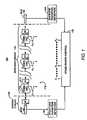
- FIG. 1illustrates an exemplary schematic block diagram of a power control circuit according to an embodiment of the present invention
- FIG. 2illustrates a timing diagram for a power shut-down procedure utilizing the power control circuit shown in FIG. 1 ;
- FIG. 3illustrates a timing diagram for a power turn-on procedure utilizing the power control circuit shown in FIG. 1 ;
- FIG. 4illustrates an exemplary schematic block diagram of an embodiment of the stage power control circuit shown in FIG. 1 ;
- FIGS. 5 ( a )-( c )illustrate detailed schematic block diagrams of the stage power control circuit shown in FIG. 1 ;
- FIG. 6illustrates a flow chart of an exemplary method employing the principles of the present invention.
- FIG. 1illustrates a power control circuit 100 managing power consumption and power delivery to a pipelined circuit 110 .
- the pipelined circuit 110includes multiple stage circuits 112 , each of which includes a power switch P N , conventional combinational logic circuitry 116 and a flip-flop 118 .
- the flip-flop 118may be a conventional flip-flop or a power saving flip-flop described in co-pending U.S. patent application Ser. No. 09/941,581 herein incorporated by reference.”
- the power control circuit 100includes a back-end transition detection circuit 125 , a stage power control circuit 130 , a front-end transition detection circuit 135 and an optional inserted buffer circuit 140 .
- the front-end transition detection circuit 135 and the back-end transition detection circuit 125may include conventional circuits for detecting signal transitions on a bus, such as a transition from a high to a low or vice versa.
- the pipelined circuit 110may perform data processing, including high-speed computations.
- the back-end transition detection circuit 125detects a transition of a signal output by the pipelined circuit 110 , such as detecting activity on a bus 150 at the output of the pipelined circuit 110 .
- the activitymay include an output of a data computation on the bus 150 from the pipelined circuit 110 .
- the bus 150may also connect each stage circuit 112 and may carry signals input to the pipelined circuit 110 .
- multiple bussesmay be used to carry data to/from the pipelined circuit 110 and to interconnect the stage circuits 112 .
- the stage power control circuit 130sequentially controls power switches P 1 -P N to suppress power supplied to the stage circuits 112 .
- stage power control circuit 130sequentially opens switches P 1 -P N , starting from the front-end of the pipelined circuit 110 (i.e., at the stage circuit 112 where the data is first input to the pipelined circuit 110 ).
- Each power switch P Nmay be opened at predetermined intervals to reduce the risk of causing an inductive spike that may result in the step-load effect.
- FIG. 2illustrates a timing diagram for a power shut-down procedure performed by the stage power control circuit 130 .
- the stage power control circuit 130suppresses power, for example, by opening a power switch P N connected to a stage circuit 112 , starting from the front-end of the pipelined circuit 110 .
- a shut-down commande.g., a signal indicating that the predetermined period of time for transition detection circuits 125 and 135 to detect a transition has expired
- the stage power control circuit 130upon the detection of a shut-down command (e.g., a signal indicating that the predetermined period of time for transition detection circuits 125 and 135 to detect a transition has expired) in the first cycle T 0 , the stage power control circuit 130 generates a signal to open switch P 1 at the time T 1 .
- a shut-down commande.g., a signal indicating that the predetermined period of time for transition detection circuits 125 and 135 to detect a transition has expired
- the stage power control circuitgenerates signals to open switches P 2 and P 3 respectively.
- the switches P 1 -P Nmay sequentially be opened until the last switch P N is opened at T N .
- the pipelined circuit 110is in a sleep mode and consumes minimal power.
- the front-end transition detection circuit 135When the front-end transition detection circuit 135 detects bus activity on the bus 150 , such as when new data is received by the pipelined circuit 110 on the bus 150 , the front-end transition detection circuit 135 transmits a wake-up signal to the stage power control circuit 130 . Then, the stage power control circuit 110 sequentially controls power switches P 1 -P N to supply power to the stage circuits 112 . For example, stage power control circuit 130 sequentially closes switches P 1 -P N , starting from the front-end of the pipelined circuit 110 (i.e., at the stage circuit 112 where the data is first input to the pipelined circuit 110 ). Each power switch P N may be closed at predetermined intervals.
- FIG. 3illustrates a timing diagram for a power turn-on procedure performed by the stage power control circuit 130 .
- the power control stage circuit 130controls a power switch P N , such that power is supplied to each stage circuit 112 starting from the front-end of the pipelined circuit 110 .
- the stage power control circuit 130upon the detection of the front end bus transition in the first cycle C 0 , the stage power control circuit 130 generates a signal to close switch P 1 at the time C 1 .
- the stage power control circuit 130generates signals to close switches P 2 and P 3 respectively.
- the switches P 1 -P Nmay sequentially be closed until the last switch P N is closed at C N .
- the pipelined circuit 110is operable to perform data computations at each stage circuit 112 .
- the circuit 100may optionally include a buffer circuit 140 . Because the transition detection circuits 125 and 135 and the stage control circuit 130 take time to respond to detected transitions, it may be necessary to insert the buffer circuit 140 in the front end of the pipelined circuit 110 to buffer the incoming data.
- the buffer circuit 140is not used in the circuit 100 when the latency of data moving through the pipeline circuit 110 becomes critical.
- the first stage circuiti.e., the stage circuit 112 at the front-end of the pipelined circuit 110
- the front-end transition detection circuit 135may receive a signal input to the first stage circuit. Then, the first stage circuit serves as a buffer for the pipelined circuit 110 . This trade-off between power consumption and speed may be determined by the system requirements.
- FIG. 4illustrates an exemplary embodiment of the stage power control circuit 130 , shown in FIG. 1 .
- the stage power control circuit 130includes a wake-up/shut-down arbitration circuit 410 , a wake-up step sequencer 420 , a shut-down step sequencer 430 and a programmable timing interval counter 440 .
- the programmable timing interval counter 440includes a timer for measuring a predetermined period of time before the pipelined circuit 110 may be placed in sleep mode.
- the back-end transition detection circuit 125shown in FIG. 1 , transmits a signal to the reset input of the programmable timing interval counter 440 when a transition is detected. This causes the programmable timing interval counter 440 to restart the timer.
- the programmable timing interval counter 440If the programmable timing interval counter 440 is not reset by the back-end transition detection circuit 125 prior to expiration of the timer (i.e., the back-end transition detection circuit 125 does not detect a transition within the predetermined period of time), the programmable timing interval counter 440 transmits a shut-down signal to the shut-down step sequencer 430 . Then, the shut-down step sequencer 430 transmits a signal to the wake-up/shut-down arbitration circuit 410 , and the wake-up/shut-down arbitration circuit 410 sequentially generates signals for opening switches P 1 -P N .
- the front-end transition detection circuit 135may output a signal to the reset input of the programmable timing interval counter 440 , similarly to the transmission signal of the back-end transition detection circuit 125 , when a transition is detected to reset the counter.
- the wake-up step sequencer 420receives a signal from the front-end detection circuit 135 when the front-end detection circuit 135 detects a transition. Then, the wake-up step sequencer transmits a signal to the wake-up/shut-down arbitration circuit 410 , causing the wakeup/shut-down arbitration circuit 410 to sequentially generate signals for closing switches P 1 -P N .
- the wake-up/shut-down arbitration circuit 410may include a multiplexer (not shown) for selecting wake-up/shut-down sequential signals to control each of switches P 1 -P N and an arbitrator (not shown) for determining which sequence(wake up or shut down) should take precedence in case of conflict. For example, a wake-up procedure typically takes precedence over a shut-down procedure. However, in order not to aggravate the step load effect, the stage power control circuit 130 may allow the shut-down procedure to temporarily progress while the wake-up procedure is gradually implemented. Also, the programming timing interval counter 440 may include a conventional timer, and the length of the predetermined period of time may be readily determined by one of ordinary skill in the art according to the configuration of the circuit 100 and other known factors.
- the length of the predetermined period of timemay also be dictated by system requirements.
- the step sequencer circuits 420 and 430are conventional circuits that may include shift registers and buffers. It will be apparent to one of ordinary skill in the art that the circuits 410 - 440 may be constructed from known circuits.
- FIG. 5 ( a )illustrates an exemplary embodiment of the stage power control circuit 130 shown in FIG. 4 .
- the wake-up/shut-down arbitration circuit 410 , the wake-up step sequencer 420 , and the shut-down step sequencer 430may be implemented by an up/down sequencer 510 , gates 520 for driving power switches P 1 -P N , a multiplexer 530 and a shift enable gate 540 .
- the up/down sequencer 510may include an N-bit shift register.
- the up/down sequencer 510is connected to the multiplexer 530 and the gate 540 for controlling shifting in the up/down sequencer 510 .
- the gate 540may output a shift enable signal to facilitate shifting the contents of the registers in the up/down sequencer 510 .
- a gate 550is connected to the programmable timing interval counter 440 for controlling the reset input for the counter 440 , and a latch 560 converts a transition detection pulse to a step signal transmitted to the gate 540 .
- the up/down sequencer 510stores the status of switches P 1 -P N .
- the multiplexer 530selects a “1” (up) or a “0” (down) to be shifted into the up/down sequencer 510 based on a signal from the programmable timing interval counter 440 .
- the front-end or back-end transition detection circuits 135 and 125detect activity (e.g., during an active power mode)
- “1's”are sequentially shifted into the up/down sequencer 510 to turn on the power switches P 1 -P N .
- the programmable timing interval counter 440transmits a wake-up select signal to the multiplexer 530 , and the multiplexer selects “1's” for transmission to the up/down sequencer 510 .
- “0's”are shifted into the up/down sequencer 510 during a shut-down procedure, such as after a predetermined period of time has expired without a bus transition being detected since the programmable timing interval counter 440 has been reset.
- the programmable timing interval counter 440outputs a shut-down select signal to the multiplexer 530 , and the multiplexer 530 selects “0's” for transmission to the up/down sequencer 510 .
- a “0”is shifted into a register in the up/down sequencer 510
- a corresponding gate 520drives the corresponding power switch P N closed.
- the programmable timing interval counter 440is not reset, all the power switches P 1 -P N will be sequentially closed. Then, the pipeline circuit 110 is in a power saving mode (i.e., a sleep mode).
- the wake-up procedurebegins, as illustrated in FIG. 5 ( c ). Then, “1's” are shifted into the up/down sequencer 510 , causing the switches P 1 -P N to be sequentially opened. The wake-up procedure may begin prior to all the power switches P 1 -P N being closed.
- circuit 100may be configured to conform with certain system specifications in power management, such as the advanced configuration and power interface specification (ACPI). Also, the circuit 100 may be used as a standalone circuit or integrated in another circuit, such as a power management unit of a chip.
- ACPIadvanced configuration and power interface specification
- FIG. 6illustrates a method 600 for minimizing power consumption for the pipelined circuit 110 .
- the stage power control unit 130determines whether no transition has been detected by either the front-end or back-end transition detection circuits 135 and 125 has at the input or output of the pipelined circuit 110 prior to the expiration of a predetermined period of time (e.g. 100 clock cycles).
- a predetermined period of timee.g. 100 clock cycles. It will be apparent to one of ordinary skill in the art that the predetermined period of time may vary according to the configuration of the circuit 100 and other known factors. The length of the predetermined period of time may also be dictated by the system requirements.
- step 615if no transition was detected prior to the expiration of the predetermined period of time, the stage power control circuit performs a sequential shut-down procedure.
- This proceduremay include sequentially opening switches P 1 -P N , such as opening one switch every clock cycle starting from P 1 .
- P 1 -P Nsequentially opening switches
- step 610If a transition was detected in step 610 , prior to the expiration of the predetermined period of time, then the stage power control circuit 130 continues active mode operation until the predetermined period of time has expired.
- the stage power control circuit 130determines whether a transition is detected at the input of the pipelined circuit 110 by the front-end transition detection circuit 135 . If a transition is detected, the stage power control circuit 130 performs a sequential turn-on procedure (step 625 ). This procedure may include sequentially closing switches P 1 -P N , such as closing one switch every clock cycle starting at P 1 . If all the switches P 1 -P N were not opened prior to the front-end transition detection circuit 135 detecting a transition (e.g., during the sequential shut down procedure performed in the step 615 ), then the stage power control circuit 130 could close those switches that were opened or wait until all the switches P 1 -P N close and let wake-up signals open switches P 1 -P N gradually.
- the stage power control circuit 130continues to open the switches P 1 -P N (step 615 ). For example, one switch may be opened after each clock cycle until all the switches are opened or until the front-end transition detection circuit 135 detects a transition.
- the method 600 shown in FIG. 6 and described abovemay generally be performed by the stage power control circuit 130 .
- the steps in the method 600can also be performed by a computer program executed by a processor, instead of the stage power control circuit 110 .
- the computer programcan exist in a variety of forms both active and inactive.
- the computer programcan exist as software comprised of program instructions or statements in source code, object code, executable code or other formats; firmware program(s); or hardware description language (HDL) files. Any of the above can be embodied on a computer readable medium, which include storage devices and signals, in compressed or uncompressed form.
- Exemplary computer readable storage devicesinclude conventional computer system RAM (random access memory), ROM (read only memory), EPROM (erasable, programmable ROM), EEPROM (electrically erasable, programmable ROM), and magnetic or optical disks or tapes.
- Exemplary computer readable signalsare signals that a computer system hosting or running the computer program can be configured to access, including signals downloaded through the Internet or other networks. Concrete examples of the foregoing include distribution of executable software program(s) of the computer program on a CD ROM or via Internet download. In a sense, the Internet itself, as an abstract entity, is a computer readable medium. The same is true of computer networks in general.
Landscapes
- Engineering & Computer Science (AREA)
- Theoretical Computer Science (AREA)
- Physics & Mathematics (AREA)
- General Engineering & Computer Science (AREA)
- General Physics & Mathematics (AREA)
- Software Systems (AREA)
- Power Sources (AREA)
Abstract
Description
Claims (21)
Priority Applications (1)
| Application Number | Priority Date | Filing Date | Title |
|---|---|---|---|
| US09/894,142US6907534B2 (en) | 2001-06-29 | 2001-06-29 | Minimizing power consumption in pipelined circuit by shutting down pipelined circuit in response to predetermined period of time having expired |
Applications Claiming Priority (1)
| Application Number | Priority Date | Filing Date | Title |
|---|---|---|---|
| US09/894,142US6907534B2 (en) | 2001-06-29 | 2001-06-29 | Minimizing power consumption in pipelined circuit by shutting down pipelined circuit in response to predetermined period of time having expired |
Publications (2)
| Publication Number | Publication Date |
|---|---|
| US20030005340A1 US20030005340A1 (en) | 2003-01-02 |
| US6907534B2true US6907534B2 (en) | 2005-06-14 |
Family
ID=25402660
Family Applications (1)
| Application Number | Title | Priority Date | Filing Date |
|---|---|---|---|
| US09/894,142Expired - LifetimeUS6907534B2 (en) | 2001-06-29 | 2001-06-29 | Minimizing power consumption in pipelined circuit by shutting down pipelined circuit in response to predetermined period of time having expired |
Country Status (1)
| Country | Link |
|---|---|
| US (1) | US6907534B2 (en) |
Cited By (12)
| Publication number | Priority date | Publication date | Assignee | Title |
|---|---|---|---|---|
| US20050265262A1 (en)* | 2002-12-26 | 2005-12-01 | Yuji Mizuguchi | Data transmission device, data transmission system, and method |
| US20060059376A1 (en)* | 2004-09-16 | 2006-03-16 | International Business Machines Corporation | Dynamic leakage control circuit |
| US7188263B1 (en)* | 2003-05-07 | 2007-03-06 | Nvidia Corporation | Method and apparatus for controlling power state of a multi-lane serial bus link having a plurality of state transition detectors wherein powering down all the state transition detectors except one |
| US20070079047A1 (en)* | 2005-09-28 | 2007-04-05 | Ati Technologies Inc. | Lane merging |
| US20070075732A1 (en)* | 2005-10-04 | 2007-04-05 | Fruhauf Serge F | System and method for using dummy cycles to mask operations in a secure microcontroller |
| US20070177581A1 (en)* | 2006-01-31 | 2007-08-02 | Rodgers Steve W | Flow control mechanism in a data processing pipeline |
| US20080204124A1 (en)* | 2007-02-28 | 2008-08-28 | Kanad Chakraborty | Fine-Grained Power Management of Synchronous and Asynchronous Datapath Circuits |
| US20080211568A1 (en)* | 2007-03-01 | 2008-09-04 | Infineon Technologies Ag | MuGFET POWER SWITCH |
| US20110032000A1 (en)* | 2009-08-07 | 2011-02-10 | Jia Di | Ultra-low power multi-threshold asynchronous circuit design |
| US8578191B2 (en) | 2010-06-10 | 2013-11-05 | Juniper Networks, Inc. | Dynamic fabric plane allocation for power savings |
| US8908709B1 (en) | 2009-01-08 | 2014-12-09 | Juniper Networks, Inc. | Methods and apparatus for power management associated with a switch fabric |
| US10209767B2 (en) | 2016-02-02 | 2019-02-19 | Apple Inc. | Power management architecture |
Families Citing this family (4)
| Publication number | Priority date | Publication date | Assignee | Title |
|---|---|---|---|---|
| KR101114984B1 (en)* | 2005-03-14 | 2012-03-06 | 삼성전자주식회사 | Method and Apparatus for Power Control Method with Variable Wake-up and Sleep latency |
| US8074086B1 (en)* | 2006-12-11 | 2011-12-06 | Cypress Semiconductor Corporation | Circuit and method for dynamic in-rush current control in a power management circuit |
| JP5228600B2 (en)* | 2008-04-23 | 2013-07-03 | 日本電気株式会社 | Information communication device, low power consumption circuit, and power consumption reduction method used therefor |
| US20200264788A1 (en)* | 2019-02-15 | 2020-08-20 | Qualcomm Incorporated | Optimal cache retention mechanism |
Citations (12)
| Publication number | Priority date | Publication date | Assignee | Title |
|---|---|---|---|---|
| JPH01102644A (en)* | 1987-09-30 | 1989-04-20 | Internatl Business Mach Corp <Ibm> | Pipeline type processor |
| US5918042A (en)* | 1996-02-29 | 1999-06-29 | Arm Limited | Dynamic logic pipeline control |
| US6140836A (en)* | 1997-03-03 | 2000-10-31 | Nippon Telegraph And Telephone Corporation | Self-timed pipelined datapath system and asynchronous signal control circuit |
| US6225827B1 (en)* | 1997-03-03 | 2001-05-01 | Nippon Telegraph & Telephone Corporation | Dynamic logic circuit and self-timed pipelined datapath system |
| US6247134B1 (en)* | 1999-03-31 | 2001-06-12 | Synopsys, Inc. | Method and system for pipe stage gating within an operating pipelined circuit for power savings |
| US6282663B1 (en)* | 1997-01-22 | 2001-08-28 | Intel Corporation | Method and apparatus for performing power management by suppressing the speculative execution of instructions within a pipelined microprocessor |
| US20020049918A1 (en)* | 2000-10-25 | 2002-04-25 | Stefanos Kaxiras | Method and apparatus for reducing leakage power in a cache memory |
| US6389512B1 (en)* | 1996-02-14 | 2002-05-14 | Advanced Micro Devices, Inc. | Microprocessor configured to detect updates to instructions outstanding within an instruction processing pipeline and computer system including same |
| US6393579B1 (en)* | 1999-12-21 | 2002-05-21 | Intel Corporation | Method and apparatus for saving power and improving performance in a collapsable pipeline using gated clocks |
| US6564328B1 (en)* | 1999-12-23 | 2003-05-13 | Intel Corporation | Microprocessor with digital power throttle |
| US6611920B1 (en)* | 2000-01-21 | 2003-08-26 | Intel Corporation | Clock distribution system for selectively enabling clock signals to portions of a pipelined circuit |
| US6667645B1 (en)* | 1999-12-20 | 2003-12-23 | Intel Corporation | Pulsed clock signal transfer circuits with dynamic latching |
- 2001
- 2001-06-29USUS09/894,142patent/US6907534B2/ennot_activeExpired - Lifetime
Patent Citations (13)
| Publication number | Priority date | Publication date | Assignee | Title |
|---|---|---|---|---|
| JPH01102644A (en)* | 1987-09-30 | 1989-04-20 | Internatl Business Mach Corp <Ibm> | Pipeline type processor |
| US6389512B1 (en)* | 1996-02-14 | 2002-05-14 | Advanced Micro Devices, Inc. | Microprocessor configured to detect updates to instructions outstanding within an instruction processing pipeline and computer system including same |
| US5918042A (en)* | 1996-02-29 | 1999-06-29 | Arm Limited | Dynamic logic pipeline control |
| US6282663B1 (en)* | 1997-01-22 | 2001-08-28 | Intel Corporation | Method and apparatus for performing power management by suppressing the speculative execution of instructions within a pipelined microprocessor |
| US6320418B1 (en)* | 1997-03-03 | 2001-11-20 | Nippon Telegraph And Telephone Corporation | Self-timed pipelined datapath system and asynchronous signal control circuit |
| US6225827B1 (en)* | 1997-03-03 | 2001-05-01 | Nippon Telegraph & Telephone Corporation | Dynamic logic circuit and self-timed pipelined datapath system |
| US6140836A (en)* | 1997-03-03 | 2000-10-31 | Nippon Telegraph And Telephone Corporation | Self-timed pipelined datapath system and asynchronous signal control circuit |
| US6247134B1 (en)* | 1999-03-31 | 2001-06-12 | Synopsys, Inc. | Method and system for pipe stage gating within an operating pipelined circuit for power savings |
| US6667645B1 (en)* | 1999-12-20 | 2003-12-23 | Intel Corporation | Pulsed clock signal transfer circuits with dynamic latching |
| US6393579B1 (en)* | 1999-12-21 | 2002-05-21 | Intel Corporation | Method and apparatus for saving power and improving performance in a collapsable pipeline using gated clocks |
| US6564328B1 (en)* | 1999-12-23 | 2003-05-13 | Intel Corporation | Microprocessor with digital power throttle |
| US6611920B1 (en)* | 2000-01-21 | 2003-08-26 | Intel Corporation | Clock distribution system for selectively enabling clock signals to portions of a pipelined circuit |
| US20020049918A1 (en)* | 2000-10-25 | 2002-04-25 | Stefanos Kaxiras | Method and apparatus for reducing leakage power in a cache memory |
Cited By (22)
| Publication number | Priority date | Publication date | Assignee | Title |
|---|---|---|---|---|
| US20050265262A1 (en)* | 2002-12-26 | 2005-12-01 | Yuji Mizuguchi | Data transmission device, data transmission system, and method |
| US7188263B1 (en)* | 2003-05-07 | 2007-03-06 | Nvidia Corporation | Method and apparatus for controlling power state of a multi-lane serial bus link having a plurality of state transition detectors wherein powering down all the state transition detectors except one |
| US20060059376A1 (en)* | 2004-09-16 | 2006-03-16 | International Business Machines Corporation | Dynamic leakage control circuit |
| US7266707B2 (en)* | 2004-09-16 | 2007-09-04 | International Business Machines Corporation | Dynamic leakage control circuit |
| US20090276558A1 (en)* | 2005-09-28 | 2009-11-05 | Ati Technologies Ulc | Lane merging |
| US20070079047A1 (en)* | 2005-09-28 | 2007-04-05 | Ati Technologies Inc. | Lane merging |
| US7937519B2 (en) | 2005-09-28 | 2011-05-03 | Ati Technologies Ulc | Lane merging |
| US7571271B2 (en)* | 2005-09-28 | 2009-08-04 | Ati Technologies Ulc | Lane merging |
| US20070075732A1 (en)* | 2005-10-04 | 2007-04-05 | Fruhauf Serge F | System and method for using dummy cycles to mask operations in a secure microcontroller |
| US7372290B2 (en)* | 2005-10-04 | 2008-05-13 | Stmicroelectronics, Inc. | System and method for using dummy cycles to mask operations in a secure microcontroller |
| US20070177581A1 (en)* | 2006-01-31 | 2007-08-02 | Rodgers Steve W | Flow control mechanism in a data processing pipeline |
| US8526303B2 (en)* | 2006-01-31 | 2013-09-03 | Broadcom Corporation | Flow control mechanism in a data processing pipeline |
| US7511535B2 (en) | 2007-02-28 | 2009-03-31 | Agere Systems Inc. | Fine-grained power management of synchronous and asynchronous datapath circuits |
| US20080204124A1 (en)* | 2007-02-28 | 2008-08-28 | Kanad Chakraborty | Fine-Grained Power Management of Synchronous and Asynchronous Datapath Circuits |
| US20080211568A1 (en)* | 2007-03-01 | 2008-09-04 | Infineon Technologies Ag | MuGFET POWER SWITCH |
| US8908709B1 (en) | 2009-01-08 | 2014-12-09 | Juniper Networks, Inc. | Methods and apparatus for power management associated with a switch fabric |
| US20110032000A1 (en)* | 2009-08-07 | 2011-02-10 | Jia Di | Ultra-low power multi-threshold asynchronous circuit design |
| US7977972B2 (en)* | 2009-08-07 | 2011-07-12 | The Board Of Trustees Of The University Of Arkansas | Ultra-low power multi-threshold asynchronous circuit design |
| US8207758B2 (en) | 2009-08-07 | 2012-06-26 | The Board Of Trustees Of The University Of Arkansas | Ultra-low power multi-threshold asynchronous circuit design |
| US8664977B2 (en) | 2009-08-07 | 2014-03-04 | The Board Of Trustees Of The University Of Arkansas | Ultra-low power multi-threshold asynchronous circuit design |
| US8578191B2 (en) | 2010-06-10 | 2013-11-05 | Juniper Networks, Inc. | Dynamic fabric plane allocation for power savings |
| US10209767B2 (en) | 2016-02-02 | 2019-02-19 | Apple Inc. | Power management architecture |
Also Published As
| Publication number | Publication date |
|---|---|
| US20030005340A1 (en) | 2003-01-02 |
Similar Documents
| Publication | Publication Date | Title |
|---|---|---|
| US6907534B2 (en) | Minimizing power consumption in pipelined circuit by shutting down pipelined circuit in response to predetermined period of time having expired | |
| JP3845642B2 (en) | Integrated circuit device having unit power adjustment mechanism | |
| US6981163B2 (en) | Method and apparatus for power mode transition in a multi-thread processor | |
| US7013406B2 (en) | Method and apparatus to dynamically change an operating frequency and operating voltage of an electronic device | |
| US5420808A (en) | Circuitry and method for reducing power consumption within an electronic circuit | |
| JP3734888B2 (en) | Microprocessor with power management function | |
| US6457131B2 (en) | System and method for power optimization in parallel units | |
| US7721129B2 (en) | Method and apparatus for reducing clock frequency during low workload periods | |
| US6946869B2 (en) | Method and structure for short range leakage control in pipelined circuits | |
| US7181188B2 (en) | Method and apparatus for entering a low power mode | |
| US7689849B2 (en) | Reduction of power consumption by throttling processor requests | |
| US20090259862A1 (en) | Clock-gated series-coupled data processing modules | |
| US20050108587A1 (en) | Demand-based method and system of CPU power management | |
| GB2424499A (en) | Method for managing the power consumption of a processor with variable wake-up and sleep latencies | |
| US10732697B2 (en) | Voltage rail coupling sequencing based on upstream voltage rail coupling status | |
| US6035315A (en) | Floating point power conservation | |
| KR100719360B1 (en) | Digital logic processing circuits, data processing apparatus including the same, system-on-chip including the same, systems including the same, and clock signal gating methods | |
| EP1573491B1 (en) | An apparatus and method for data bus power control | |
| JP4903272B2 (en) | Highly efficient power management technology for computer systems | |
| US20060036881A1 (en) | Processor circuitry |
Legal Events
| Date | Code | Title | Description |
|---|---|---|---|
| AS | Assignment | Owner name:HEWLETT-PACKARD COMPANY, COLORADO Free format text:ASSIGNMENT OF ASSIGNORS INTEREST;ASSIGNOR:KU, JOSEPH;REEL/FRAME:012525/0667 Effective date:20010530 | |
| AS | Assignment | Owner name:HEWLETT-PACKARD DEVELOPMENT COMPANY L.P., TEXAS Free format text:ASSIGNMENT OF ASSIGNORS INTEREST;ASSIGNOR:HEWLETT-PACKARD COMPANY;REEL/FRAME:014061/0492 Effective date:20030926 Owner name:HEWLETT-PACKARD DEVELOPMENT COMPANY L.P.,TEXAS Free format text:ASSIGNMENT OF ASSIGNORS INTEREST;ASSIGNOR:HEWLETT-PACKARD COMPANY;REEL/FRAME:014061/0492 Effective date:20030926 | |
| STCF | Information on status: patent grant | Free format text:PATENTED CASE | |
| FPAY | Fee payment | Year of fee payment:4 | |
| FPAY | Fee payment | Year of fee payment:8 | |
| AS | Assignment | Owner name:HEWLETT PACKARD ENTERPRISE DEVELOPMENT LP, TEXAS Free format text:ASSIGNMENT OF ASSIGNORS INTEREST;ASSIGNOR:HEWLETT-PACKARD DEVELOPMENT COMPANY, L.P.;REEL/FRAME:037079/0001 Effective date:20151027 | |
| FPAY | Fee payment | Year of fee payment:12 |