US6907329B2 - Method and device for activating and/or deactivating distributed control units - Google Patents
Method and device for activating and/or deactivating distributed control unitsDownload PDFInfo
- Publication number
- US6907329B2 US6907329B2US10/317,826US31782602AUS6907329B2US 6907329 B2US6907329 B2US 6907329B2US 31782602 AUS31782602 AUS 31782602AUS 6907329 B2US6907329 B2US 6907329B2
- Authority
- US
- United States
- Prior art keywords
- control units
- decentralized control
- control unit
- decentralized
- sensors
- Prior art date
- Legal status (The legal status is an assumption and is not a legal conclusion. Google has not performed a legal analysis and makes no representation as to the accuracy of the status listed.)
- Expired - Fee Related, expires
Links
- 238000000034methodMethods0.000titleclaimsabstractdescription12
- 230000003213activating effectEffects0.000titleclaimsabstract4
- 230000009849deactivationEffects0.000claimsabstractdescription9
- 230000004913activationEffects0.000claimsabstractdescription8
- 230000009977dual effectEffects0.000claimsdescription5
- 238000012423maintenanceMethods0.000claimsdescription3
- 230000015654memoryEffects0.000description10
- 230000006870functionEffects0.000description4
- 238000010586diagramMethods0.000description3
- 230000009471actionEffects0.000description2
- 230000002093peripheral effectEffects0.000description2
- 102100021624Acid-sensing ion channel 1Human genes0.000description1
- 101710099904Acid-sensing ion channel 1Proteins0.000description1
- 101100220046Bos taurus CD36 geneProteins0.000description1
- 108091006146ChannelsProteins0.000description1
- 101100060179Drosophila melanogaster Clk geneProteins0.000description1
- 101100315759Komagataella pastoris PEX4 geneProteins0.000description1
- 101150038023PEX1 geneProteins0.000description1
- 101100407813Saccharomyces cerevisiae (strain ATCC 204508 / S288c) PEX10 geneProteins0.000description1
- 101100407812Schizosaccharomyces pombe (strain 972 / ATCC 24843) pas4 geneProteins0.000description1
- 230000002457bidirectional effectEffects0.000description1
- 238000003745diagnosisMethods0.000description1
- 101150014555pas-1 geneProteins0.000description1
- 230000007420reactivationEffects0.000description1
- 230000001960triggered effectEffects0.000description1
Images


Classifications
- G—PHYSICS
- G05—CONTROLLING; REGULATING
- G05B—CONTROL OR REGULATING SYSTEMS IN GENERAL; FUNCTIONAL ELEMENTS OF SUCH SYSTEMS; MONITORING OR TESTING ARRANGEMENTS FOR SUCH SYSTEMS OR ELEMENTS
- G05B19/00—Programme-control systems
- G05B19/02—Programme-control systems electric
- G05B19/04—Programme control other than numerical control, i.e. in sequence controllers or logic controllers
- G05B19/042—Programme control other than numerical control, i.e. in sequence controllers or logic controllers using digital processors
- G05B19/0421—Multiprocessor system
- G—PHYSICS
- G05—CONTROLLING; REGULATING
- G05B—CONTROL OR REGULATING SYSTEMS IN GENERAL; FUNCTIONAL ELEMENTS OF SUCH SYSTEMS; MONITORING OR TESTING ARRANGEMENTS FOR SUCH SYSTEMS OR ELEMENTS
- G05B2219/00—Program-control systems
- G05B2219/20—Pc systems
- G05B2219/22—Pc multi processor system
- G05B2219/2219—Processor starts application program only if it receives predetermined data
- G—PHYSICS
- G05—CONTROLLING; REGULATING
- G05B—CONTROL OR REGULATING SYSTEMS IN GENERAL; FUNCTIONAL ELEMENTS OF SUCH SYSTEMS; MONITORING OR TESTING ARRANGEMENTS FOR SUCH SYSTEMS OR ELEMENTS
- G05B2219/00—Program-control systems
- G05B2219/20—Pc systems
- G05B2219/22—Pc multi processor system
- G05B2219/2236—Master determines critical time when each of slaves must be controlled
Definitions
- a distributed control system and/or analysis system in a motor vehicleis known from German Patent Application No. 1 01 10 042.6 of Mar. 2, 2001 (not a prior publication).
- decentralized control unitse.g., sensors having corresponding electronic units for control and/or analysis
- a data lineleads from the central control unit to each decentralized control unit.
- Both the decentralized control units and the central control unitare designed for transmitting and receiving signals (data).
- the preferred applicationis based on the general field of environment sensors for motor vehicles, in particular radar sensor systems.
- the interface between the central control unit and decentralized control unitsis designed as a current-based dual wire interface. In the preferred embodiment, power is supplied from the central control unit to the distributed (decentralized) control units, resulting in a very high maximum power consumption.
- the distributed (decentralized) control unitsare controlled in a state of reduced power consumption, at least in certain operating situations, so that the total power consumption of the distributed system is greatly reduced.
- the power-saving modeis activated by transmitting corresponding data from the central control unit to the selected decentralized units.
- this current managementmakes current peaks preventable and cost savings achievable, e.g., with regard to thermal management and power loss in input protection circuits and in the power supply to the decentralized control units and in the associated mechanical system.
- the decentralized control systemmay have a continuous power supply (terminal 30 ). Furthermore, it is also possible to perform a system diagnosis with the ignition switched off.
- the power emitted into the environmentis reduced significantly on the average when used in conjunction with a radar system for environment sensors in a motor vehicle. Furthermore, there is the possibility of reducing the mutual interference of the radar sensors because active sensors are selected and unneeded sensors are shut down, depending on the operating situation.
- FIG. 1shows a schematic diagram of a distributed system.
- FIG. 2shows a detailed embodiment of the central control unit.
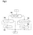
- FIG. 3illustrates the implementation of the activation and/or deactivation of the decentralized control units and/or selected decentralized control units on the basis of a simplified flow chart.
- FIG. 1shows a schematic diagram of a decentralized control system having a central control unit 10 which may be connected to other control units via a data communication system 12 .
- a total of six decentralized control units 12 , 14 , 16 , 18 , 20 , 22are connected to central control unit 10 as part of a point-to-point link.
- a bidirectional interface 24 , 26 , 28 , 30 , 32 , 34is provided between the central control unit and each decentralized control unit, in the preferred exemplary embodiment being a current-based dual wire interface.
- Data exchangetakes place between the central control unit and the decentralized control units over the particular interface, the central control unit preferably transmitting data to and receiving data from the decentralized control units and each decentralized control unit transmitting data to or receiving data from the central control unit.
- a preferred applicationis in the field of environment sensors for a motor vehicle, e.g., radar sensors, infrared or ultrasonic sensors, lasers and video cameras. These sensors and thus the decentralized control units are located on the outside of the vehicle, e.g., in the bumpers, on the vehicle side while the central control unit is mounted at a central location (e.g., in the interior). Thus, this is a system having distributed intelligent components (i.e., equipped with at least one processor). Depending on the application, more or fewer decentralized control units may be provided. In addition, however, the procedure described below may also be used with any other interface between two control units.
- the applicationis not limited to the field of environment sensing of motor vehicles but instead may also be used in other decentralized systems of motor vehicles, e.g., brake systems, engine control systems, etc., or in systems outside of motor vehicles.
- FIG. 2shows a detailed diagram of the interface-specific parts of central control unit 10 and a selected decentralized control unit 12 . Furthermore, interfaces 26 , 28 , 30 to other decentralized control units are also indicated.
- Central control unit 10essentially includes a computer core and an interface module 102 (ASIC1). Preferably current-based dual wire interfaces to the decentralized control units are implemented.
- Computer core of central control unit 10includes a computer and an Serial Peripheral Interface (SPI interface), which is connected via a data line to an SPI interface of interface module 102 .
- SPI interfaceSerial Peripheral Interface
- interface module 102has transmit memories, each of which is connected to current-based dual wire interface (PAS 1 through PAS 4 ).
- PAS 1 through PAS 4Current-based dual wire interface
- Data to be transmittedis delivered by microcomputer to module 102 via the SPI interface and is stored temporarily in the particular transmit memory, indicating whether the data is to be transmitted to all decentralized units, a group thereof or to an individual unit. The data is written into the memories accordingly.
- the stored datais transmitted from these memories via the particular interface to the decentralized control unit provided their reception memories are free.
- data from a decentralized control unitis received by interface module 102 and stored in at least one receive memory E 1 , E 2 (per receive channel).
- the received datais read out of this at least one memory by the computer via a multiplexer MUX and the SPI interface. To do so, the presence of data to be retrieved is signaled to the computer by the interface module over connecting line 1038 .
- the elements mentioned aboveare hardware elements whose implementation is essentially known.
- the size and number of memoriesis selected according to the application case. In one application example, a transmit memory having a length of one byte has proven suitable. It should be pointed out that the SPI interface and/or the PAS interface has its/their own buffer memories in one embodiment.
- interface module 104is an ASIC.
- the system shown hereallows microcomputer 100 to transmit data to all or individual selected decentralized control units by transmitting data over the SPI interface to interface module 104 , in particular through an appropriate command.
- the decentralized control unitsare supplied with power via the central control unit.
- the power consumption per decentralized control unitis 300 mA, and a maximum of 12 sensors are connected to one central control unit. This yields a maximum sensor-induced power consumption of 3.6 A, i.e., a relatively high value. It is therefore provided that one or more sensors, depending on the operating state of the vehicle, be brought into an operating state having minimal power consumption by the central control unit via the interface.
- the active functions of the decentralized control unitin the case of a radar sensor, the transmitting and receiving functions of the radar signal in particular
- the basic operation of the interfacein particular its readiness to receive
- Examples of such operating situations in which at least some of the decentralized control units may be shut downinclude driving at a high speed at which lateral radar sensors need not be active or driving in forward gear, when rear radar sensors might not need to be active, etc.
- Other operating statesinclude the vehicle standing still, a maintenance procedure, etc.
- a data set ordering the particular decentralized control unit to shut down and wait for a wake-up commandis sent via an SPI command from the microcomputer of the central control unit over the interfaces leading to the selected decentralized control units.
- the commandis composed of the data itself, the selected control units being encoded by a suitable identifier. Either all or a predetermined selection of the decentralized control units may be switched by the microcomputer to a power-saving mode.
- FIG. 3shows a flow chart illustrating the sequence in conjunction with activation and deactivation of all or individual decentralized control units.
- the simplified flow chartrepresents a program running in the microcomputer of the central control unit. A similar program is run through for each decentralized control unit or a group of control units at certain points in time.
- First a checkis performed in step 200 to ascertain whether the control unit is currently in a power-saving mode. If this is the case, then step 202 determines whether the prevailing operating state is one in which the sensor is to be activated.
- a corresponding command or data setis output by the microcomputer via the Serial Peripheral Interface (SPI interface) and the current-based interface to the corresponding decentralized control unit in step 204 , so that reactivation of the decentralized control unit is triggered. If the control unit is not to be activated, there is no action.
- SPI interfaceSerial Peripheral Interface
- step 206determines whether the prevailing operating state is one in which the decentralized control unit may be switched to power-saving mode. If this is the case, then according to step 208 a corresponding command or data set is output as explained above. Otherwise there is no action.
- a corresponding programis not implemented for individual sensors but instead for a group of sensors (e.g., left sensors, right sensors, forward sensors, rear sensors).
- the procedure described hereis applicable not only in conjunction with systems for environment sensing of a motor vehicle but also in other decentralized systems in which individual decentralized control units are switchable to a power-saving mode.
- the power-saving modeis implemented so that the parts essential to the central control unit are disconnected from the power supply while their reception readiness via the current-based interface is maintained, i.e., there is still a power connection from the central unit to the decentralized unit.
Landscapes
- Physics & Mathematics (AREA)
- General Physics & Mathematics (AREA)
- Engineering & Computer Science (AREA)
- Automation & Control Theory (AREA)
- Radar Systems Or Details Thereof (AREA)
- Traffic Control Systems (AREA)
- Programmable Controllers (AREA)
Abstract
Description
A distributed control system and/or analysis system in a motor vehicle is known from German Patent Application No. 1 01 10 042.6 of Mar. 2, 2001 (not a prior publication). In this system, decentralized control units (e.g., sensors having corresponding electronic units for control and/or analysis) are connected by a point-to-point link to a central control unit for data exchange. A data line leads from the central control unit to each decentralized control unit. Both the decentralized control units and the central control unit are designed for transmitting and receiving signals (data). The preferred application is based on the general field of environment sensors for motor vehicles, in particular radar sensor systems. The interface between the central control unit and decentralized control units is designed as a current-based dual wire interface. In the preferred embodiment, power is supplied from the central control unit to the distributed (decentralized) control units, resulting in a very high maximum power consumption.
It is especially advantageous that through appropriate control of the distributed (decentralized) control units, the latter are controlled in a state of reduced power consumption, at least in certain operating situations, so that the total power consumption of the distributed system is greatly reduced.
In an advantageous manner, the power-saving mode is activated by transmitting corresponding data from the central control unit to the selected decentralized units.
It is especially advantageous that this current management makes current peaks preventable and cost savings achievable, e.g., with regard to thermal management and power loss in input protection circuits and in the power supply to the decentralized control units and in the associated mechanical system.
Furthermore, more reliable operation of the decentralized system due to the standby/wake-up capability is also advantageous. In this way, the decentralized control system may have a continuous power supply (terminal30). Furthermore, it is also possible to perform a system diagnosis with the ignition switched off.
In an especially advantageous manner, due to this measure, the power emitted into the environment is reduced significantly on the average when used in conjunction with a radar system for environment sensors in a motor vehicle. Furthermore, there is the possibility of reducing the mutual interference of the radar sensors because active sensors are selected and unneeded sensors are shut down, depending on the operating situation.
A preferred application is in the field of environment sensors for a motor vehicle, e.g., radar sensors, infrared or ultrasonic sensors, lasers and video cameras. These sensors and thus the decentralized control units are located on the outside of the vehicle, e.g., in the bumpers, on the vehicle side while the central control unit is mounted at a central location (e.g., in the interior). Thus, this is a system having distributed intelligent components (i.e., equipped with at least one processor). Depending on the application, more or fewer decentralized control units may be provided. In addition, however, the procedure described below may also be used with any other interface between two control units. The application is not limited to the field of environment sensing of motor vehicles but instead may also be used in other decentralized systems of motor vehicles, e.g., brake systems, engine control systems, etc., or in systems outside of motor vehicles.
The elements mentioned above are hardware elements whose implementation is essentially known. The size and number of memories is selected according to the application case. In one application example, a transmit memory having a length of one byte has proven suitable. It should be pointed out that the SPI interface and/or the PAS interface has its/their own buffer memories in one embodiment.
The sequence inmodule 102 described below is hardwired in the module. In the preferred exemplary embodiment,interface module 104 is an ASIC.
The system shown here allowsmicrocomputer 100 to transmit data to all or individual selected decentralized control units by transmitting data over the SPI interface tointerface module 104, in particular through an appropriate command. In the preferred embodiment, the decentralized control units are supplied with power via the central control unit. In a preferred application case, it has been found that the power consumption per decentralized control unit (radar sensor) is 300 mA, and a maximum of 12 sensors are connected to one central control unit. This yields a maximum sensor-induced power consumption of 3.6 A, i.e., a relatively high value. It is therefore provided that one or more sensors, depending on the operating state of the vehicle, be brought into an operating state having minimal power consumption by the central control unit via the interface. In this operating state, the active functions of the decentralized control unit (in the case of a radar sensor, the transmitting and receiving functions of the radar signal in particular) are shut down while the basic operation of the interface, in particular its readiness to receive, is maintained. This makes it possible to greatly reduce power consumption. Examples of such operating situations in which at least some of the decentralized control units may be shut down include driving at a high speed at which lateral radar sensors need not be active or driving in forward gear, when rear radar sensors might not need to be active, etc. Other operating states include the vehicle standing still, a maintenance procedure, etc.
Thus, if the currently active function of one or more decentralized control units is not needed during driving operation or at a standstill or during maintenance work, then a data set ordering the particular decentralized control unit to shut down and wait for a wake-up command is sent via an SPI command from the microcomputer of the central control unit over the interfaces leading to the selected decentralized control units. In a preferred embodiment, the command is composed of the data itself, the selected control units being encoded by a suitable identifier. Either all or a predetermined selection of the decentralized control units may be switched by the microcomputer to a power-saving mode. If the function of the control system again requires an active decentralized control unit, which is currently in an off state, however, then a corresponding command of the microcomputer of the central control unit and/or a corresponding data set is relayed via the corresponding interface to the decentralized control unit, ordering it to turn on again (wake-up command).
If the corresponding control unit is not in power-saving mode, then a check is performed instep 206 to determine whether the prevailing operating state is one in which the decentralized control unit may be switched to power-saving mode. If this is the case, then according to step208 a corresponding command or data set is output as explained above. Otherwise there is no action.
In other application examples, a corresponding program is not implemented for individual sensors but instead for a group of sensors (e.g., left sensors, right sensors, forward sensors, rear sensors).
The procedure described here is applicable not only in conjunction with systems for environment sensing of a motor vehicle but also in other decentralized systems in which individual decentralized control units are switchable to a power-saving mode.
The power-saving mode is implemented so that the parts essential to the central control unit are disconnected from the power supply while their reception readiness via the current-based interface is maintained, i.e., there is still a power connection from the central unit to the decentralized unit.
Claims (11)
1. A method of at least one of activating and deactivating distributed control units, comprising:
providing point-to-point wiring between a central control unit and decentralized control units;
transmitting a corresponding signal from the central control unit to a corresponding decentralized control unit via an interface, the signal being one of an activation signal and a deactivation signal; and
prompting, by the central control unit, at least one of an activation and a deactivation of selected ones of the decentralized control units via one of a command and a data set;
wherein the decentralized control units are controlled in a state of reduced power consumption.
2. The method according toclaim 1 , wherein the activation/deactivation command is valid for one of: (a) individual ones of the decentralized control units, (b) a predetermined group of the decentralized control units, and (c) all of the decentralized control units.
3. The method according toclaim 1 , wherein the decentralized control units control sensors for environment sensing of a motor vehicle, deactivation of individual ones of the sensors being performed in predetermined operating states of the vehicle.
4. The method according toclaim 3 , wherein the predetermined operating states include a state of one of: (a) high speed, (b) vehicle standstill, and (c) vehicle maintenance.
5. The method according toclaim 1 , wherein the at least one of the activation and deactivation is prompted by a microcomputer of the central control unit via an SPI interface and a current-based dual wire interface.
6. The method according toclaim 1 , wherein the state of reduced power consumption prevents current peaks in a power supply to the decentralized control units.
7. The method according toclaim 1 , wherein the decentralized control units have a continuous power supply via a standby/wake-up capability.
8. A device for at least one of activating and deactivating distributed control units, comprising:
a central control unit;
decentralized control units;
a point-to-point interface linking the central control unit to the decentralized control units;
a microcomputer generating a command for one of activation and deactivation and transmitting the command to the decentralized control units; and
an interface module receiving the command of the microcomputer via an interface and delivering the command via another interface to selected ones of the decentralized control units;
wherein the decentralized control units are controlled in a state of reduced power consumption.
9. The device according toclaim 8 , wherein the decentralized control units are for sensors for sensing an environment of a motor vehicle.
10. The device according toclaim 9 , wherein the sensors are radar sensors.
11. The device according toclaim 10 , wherein interference between the radar sensors is reduced via selecting active sensors and shutting down unneeded sensors.
Applications Claiming Priority (2)
| Application Number | Priority Date | Filing Date | Title |
|---|---|---|---|
| DE10161669ADE10161669A1 (en) | 2001-12-14 | 2001-12-14 | Method of activating or deactivating distributed control units, e.g. for motor vehicle radar sensors, using central control unit, by using commands transmitted via interface and point-to-point wiring |
| DE10161669.4 | 2001-12-14 |
Publications (2)
| Publication Number | Publication Date |
|---|---|
| US20030229402A1 US20030229402A1 (en) | 2003-12-11 |
| US6907329B2true US6907329B2 (en) | 2005-06-14 |
Family
ID=7709336
Family Applications (1)
| Application Number | Title | Priority Date | Filing Date |
|---|---|---|---|
| US10/317,826Expired - Fee RelatedUS6907329B2 (en) | 2001-12-14 | 2002-12-12 | Method and device for activating and/or deactivating distributed control units |
Country Status (3)
| Country | Link |
|---|---|
| US (1) | US6907329B2 (en) |
| JP (1) | JP2003195913A (en) |
| DE (1) | DE10161669A1 (en) |
Cited By (53)
| Publication number | Priority date | Publication date | Assignee | Title |
|---|---|---|---|---|
| US20050071070A1 (en)* | 2003-09-26 | 2005-03-31 | Peter Nilsson | Brake system with distributed electronic control units responsive to sensor input |
| US20080169965A1 (en)* | 2006-10-26 | 2008-07-17 | Minichshofer Dipl Ing Jurgen | Driver assistance system |
| US20080258961A1 (en)* | 2007-04-23 | 2008-10-23 | Mitsubishi Electric Corporation | In-vehicle radar system |
| US20110046844A1 (en)* | 2007-10-22 | 2011-02-24 | Mats Honner | System and method for changing the state of vehicle components |
| USD648641S1 (en) | 2009-10-21 | 2011-11-15 | Lennox Industries Inc. | Thin cover plate for an electronic system controller |
| USD648642S1 (en) | 2009-10-21 | 2011-11-15 | Lennox Industries Inc. | Thin cover plate for an electronic system controller |
| US8239066B2 (en) | 2008-10-27 | 2012-08-07 | Lennox Industries Inc. | System and method of use for a user interface dashboard of a heating, ventilation and air conditioning network |
| US8255086B2 (en) | 2008-10-27 | 2012-08-28 | Lennox Industries Inc. | System recovery in a heating, ventilation and air conditioning network |
| US8260444B2 (en) | 2010-02-17 | 2012-09-04 | Lennox Industries Inc. | Auxiliary controller of a HVAC system |
| US8295981B2 (en) | 2008-10-27 | 2012-10-23 | Lennox Industries Inc. | Device commissioning in a heating, ventilation and air conditioning network |
| US8352080B2 (en) | 2008-10-27 | 2013-01-08 | Lennox Industries Inc. | Communication protocol system and method for a distributed-architecture heating, ventilation and air conditioning network |
| US8352081B2 (en) | 2008-10-27 | 2013-01-08 | Lennox Industries Inc. | Communication protocol system and method for a distributed-architecture heating, ventilation and air conditioning network |
| US8433446B2 (en) | 2008-10-27 | 2013-04-30 | Lennox Industries, Inc. | Alarm and diagnostics system and method for a distributed-architecture heating, ventilation and air conditioning network |
| US8437878B2 (en) | 2008-10-27 | 2013-05-07 | Lennox Industries Inc. | Alarm and diagnostics system and method for a distributed architecture heating, ventilation and air conditioning network |
| US8437877B2 (en) | 2008-10-27 | 2013-05-07 | Lennox Industries Inc. | System recovery in a heating, ventilation and air conditioning network |
| US8442693B2 (en) | 2008-10-27 | 2013-05-14 | Lennox Industries, Inc. | System and method of use for a user interface dashboard of a heating, ventilation and air conditioning network |
| US8452906B2 (en) | 2008-10-27 | 2013-05-28 | Lennox Industries, Inc. | Communication protocol system and method for a distributed-architecture heating, ventilation and air conditioning network |
| US8452456B2 (en) | 2008-10-27 | 2013-05-28 | Lennox Industries Inc. | System and method of use for a user interface dashboard of a heating, ventilation and air conditioning network |
| US8463442B2 (en) | 2008-10-27 | 2013-06-11 | Lennox Industries, Inc. | Alarm and diagnostics system and method for a distributed architecture heating, ventilation and air conditioning network |
| US8463443B2 (en) | 2008-10-27 | 2013-06-11 | Lennox Industries, Inc. | Memory recovery scheme and data structure in a heating, ventilation and air conditioning network |
| US8543243B2 (en) | 2008-10-27 | 2013-09-24 | Lennox Industries, Inc. | System and method of use for a user interface dashboard of a heating, ventilation and air conditioning network |
| US8548630B2 (en) | 2008-10-27 | 2013-10-01 | Lennox Industries, Inc. | Alarm and diagnostics system and method for a distributed-architecture heating, ventilation and air conditioning network |
| US8560125B2 (en) | 2008-10-27 | 2013-10-15 | Lennox Industries | Communication protocol system and method for a distributed-architecture heating, ventilation and air conditioning network |
| US8564400B2 (en) | 2008-10-27 | 2013-10-22 | Lennox Industries, Inc. | Communication protocol system and method for a distributed-architecture heating, ventilation and air conditioning network |
| US8600559B2 (en) | 2008-10-27 | 2013-12-03 | Lennox Industries Inc. | Method of controlling equipment in a heating, ventilation and air conditioning network |
| US8600558B2 (en) | 2008-10-27 | 2013-12-03 | Lennox Industries Inc. | System recovery in a heating, ventilation and air conditioning network |
| US8615326B2 (en) | 2008-10-27 | 2013-12-24 | Lennox Industries Inc. | System and method of use for a user interface dashboard of a heating, ventilation and air conditioning network |
| US8655491B2 (en) | 2008-10-27 | 2014-02-18 | Lennox Industries Inc. | Alarm and diagnostics system and method for a distributed architecture heating, ventilation and air conditioning network |
| US8655490B2 (en) | 2008-10-27 | 2014-02-18 | Lennox Industries, Inc. | System and method of use for a user interface dashboard of a heating, ventilation and air conditioning network |
| US8661165B2 (en) | 2008-10-27 | 2014-02-25 | Lennox Industries, Inc. | Device abstraction system and method for a distributed architecture heating, ventilation and air conditioning system |
| US8694164B2 (en) | 2008-10-27 | 2014-04-08 | Lennox Industries, Inc. | Interactive user guidance interface for a heating, ventilation and air conditioning system |
| US8725298B2 (en) | 2008-10-27 | 2014-05-13 | Lennox Industries, Inc. | Alarm and diagnostics system and method for a distributed architecture heating, ventilation and conditioning network |
| US8744629B2 (en) | 2008-10-27 | 2014-06-03 | Lennox Industries Inc. | System and method of use for a user interface dashboard of a heating, ventilation and air conditioning network |
| US8762666B2 (en) | 2008-10-27 | 2014-06-24 | Lennox Industries, Inc. | Backup and restoration of operation control data in a heating, ventilation and air conditioning network |
| US8774210B2 (en) | 2008-10-27 | 2014-07-08 | Lennox Industries, Inc. | Communication protocol system and method for a distributed-architecture heating, ventilation and air conditioning network |
| US8788100B2 (en) | 2008-10-27 | 2014-07-22 | Lennox Industries Inc. | System and method for zoning a distributed-architecture heating, ventilation and air conditioning network |
| US8798796B2 (en) | 2008-10-27 | 2014-08-05 | Lennox Industries Inc. | General control techniques in a heating, ventilation and air conditioning network |
| US8802981B2 (en) | 2008-10-27 | 2014-08-12 | Lennox Industries Inc. | Flush wall mount thermostat and in-set mounting plate for a heating, ventilation and air conditioning system |
| US8855825B2 (en) | 2008-10-27 | 2014-10-07 | Lennox Industries Inc. | Device abstraction system and method for a distributed-architecture heating, ventilation and air conditioning system |
| US8874815B2 (en) | 2008-10-27 | 2014-10-28 | Lennox Industries, Inc. | Communication protocol system and method for a distributed architecture heating, ventilation and air conditioning network |
| US8892797B2 (en) | 2008-10-27 | 2014-11-18 | Lennox Industries Inc. | Communication protocol system and method for a distributed-architecture heating, ventilation and air conditioning network |
| US8977794B2 (en) | 2008-10-27 | 2015-03-10 | Lennox Industries, Inc. | Communication protocol system and method for a distributed-architecture heating, ventilation and air conditioning network |
| US8994539B2 (en) | 2008-10-27 | 2015-03-31 | Lennox Industries, Inc. | Alarm and diagnostics system and method for a distributed-architecture heating, ventilation and air conditioning network |
| US20150167994A1 (en)* | 2012-05-30 | 2015-06-18 | Carrier Corporation | Hvac control system |
| US9152155B2 (en) | 2008-10-27 | 2015-10-06 | Lennox Industries Inc. | Device abstraction system and method for a distributed-architecture heating, ventilation and air conditioning system |
| US9261888B2 (en) | 2008-10-27 | 2016-02-16 | Lennox Industries Inc. | System and method of use for a user interface dashboard of a heating, ventilation and air conditioning network |
| US9268345B2 (en) | 2008-10-27 | 2016-02-23 | Lennox Industries Inc. | System and method of use for a user interface dashboard of a heating, ventilation and air conditioning network |
| US9325517B2 (en) | 2008-10-27 | 2016-04-26 | Lennox Industries Inc. | Device abstraction system and method for a distributed-architecture heating, ventilation and air conditioning system |
| US9377768B2 (en) | 2008-10-27 | 2016-06-28 | Lennox Industries Inc. | Memory recovery scheme and data structure in a heating, ventilation and air conditioning network |
| US9432208B2 (en) | 2008-10-27 | 2016-08-30 | Lennox Industries Inc. | Device abstraction system and method for a distributed architecture heating, ventilation and air conditioning system |
| US9632490B2 (en) | 2008-10-27 | 2017-04-25 | Lennox Industries Inc. | System and method for zoning a distributed architecture heating, ventilation and air conditioning network |
| US9651925B2 (en) | 2008-10-27 | 2017-05-16 | Lennox Industries Inc. | System and method for zoning a distributed-architecture heating, ventilation and air conditioning network |
| US9678486B2 (en) | 2008-10-27 | 2017-06-13 | Lennox Industries Inc. | Device abstraction system and method for a distributed-architecture heating, ventilation and air conditioning system |
Families Citing this family (9)
| Publication number | Priority date | Publication date | Assignee | Title |
|---|---|---|---|---|
| CN100538569C (en)* | 2004-02-28 | 2009-09-09 | Abb研究有限公司 | process control system and method for operating such a system |
| US7873962B2 (en)* | 2005-04-08 | 2011-01-18 | Xerox Corporation | Distributed control systems and methods that selectively activate respective coordinators for respective tasks |
| JP4544325B2 (en)* | 2008-03-25 | 2010-09-15 | 株式会社デンソー | In-vehicle device |
| DE102008038640A1 (en)* | 2008-08-12 | 2010-02-18 | Pex Kabeltechnik Gmbh | Method for controlling and / or monitoring functions |
| JP2010181312A (en)* | 2009-02-06 | 2010-08-19 | Panasonic Corp | Angular velocity sensor |
| US8763380B2 (en) | 2010-01-14 | 2014-07-01 | Toyota Jidosha Kabushiki Kaisha | Catalyst temperature control device |
| GB201102594D0 (en) | 2011-02-15 | 2011-03-30 | Nordic Semiconductor Asa | Serial interface |
| DE102017003120A1 (en) | 2017-03-30 | 2018-10-04 | Nils Dreifke | Planar transport system and method for the simultaneous, independent handling of objects |
| CN112424713A (en)* | 2018-08-23 | 2021-02-26 | 西门子股份公司 | Artificial intelligence computing device, control method and device, engineer station and industrial automation system |
Citations (15)
| Publication number | Priority date | Publication date | Assignee | Title |
|---|---|---|---|---|
| US5521579A (en)* | 1993-04-26 | 1996-05-28 | Mercedes-Benz Ag | Method for providing guiding assistance for a vehicle in changing lane |
| US5646612A (en)* | 1995-02-09 | 1997-07-08 | Daewoo Electronics Co., Ltd. | Method for avoiding collision of vehicle and apparatus for performing the same |
| US5654715A (en)* | 1995-12-15 | 1997-08-05 | Honda Giken Kogyo Kabushiki Kaisha | Vehicle-surroundings monitoring apparatus |
| US5835873A (en)* | 1997-02-21 | 1998-11-10 | Breed Automotive Technology, Inc. | Vehicle safety system with safety device controllers |
| US6151539A (en)* | 1997-11-03 | 2000-11-21 | Volkswagen Ag | Autonomous vehicle arrangement and method for controlling an autonomous vehicle |
| US6195597B1 (en)* | 1998-04-17 | 2001-02-27 | Sony Corporation | Onboard information processing apparatus and automobile |
| US6307622B1 (en)* | 1999-02-17 | 2001-10-23 | Infineon Technologies North America Corp. | Correlation based optical ranging and proximity detector |
| US6381532B1 (en)* | 2000-09-20 | 2002-04-30 | Visteon Global Technologies, Inc. | Queued port data controller for microprocessor-based engine control applications |
| US6448671B1 (en)* | 1999-08-05 | 2002-09-10 | Trw Inc. | Distributed vehicle safety system having fault protection |
| DE10110042A1 (en) | 2001-03-02 | 2002-10-10 | Bosch Gmbh Robert | Control / evaluation system for a sensor network |
| US6501368B1 (en)* | 1999-09-20 | 2002-12-31 | Vansco Electronics Ltd. | Electrical control apparatus including a plurality of programmable modules |
| US6549145B2 (en)* | 1999-09-08 | 2003-04-15 | Pni Corporation | Radar/laser detection device with multi-sensing and reporting capability |
| US6553297B2 (en)* | 2000-07-26 | 2003-04-22 | Denso Corporation | Integrated vehicle control system |
| US20030120396A1 (en)* | 2000-06-30 | 2003-06-26 | Vasco Vollmer | Method,device and bus manager for operating a device that is connected to a motor vehicle communications network |
| US6728603B2 (en)* | 2001-02-08 | 2004-04-27 | Electronic Data Systems Corporation | System and method for managing wireless vehicular communications |
- 2001
- 2001-12-14DEDE10161669Apatent/DE10161669A1/ennot_activeWithdrawn
- 2002
- 2002-12-12JPJP2002361355Apatent/JP2003195913A/enactivePending
- 2002-12-12USUS10/317,826patent/US6907329B2/ennot_activeExpired - Fee Related
Patent Citations (15)
| Publication number | Priority date | Publication date | Assignee | Title |
|---|---|---|---|---|
| US5521579A (en)* | 1993-04-26 | 1996-05-28 | Mercedes-Benz Ag | Method for providing guiding assistance for a vehicle in changing lane |
| US5646612A (en)* | 1995-02-09 | 1997-07-08 | Daewoo Electronics Co., Ltd. | Method for avoiding collision of vehicle and apparatus for performing the same |
| US5654715A (en)* | 1995-12-15 | 1997-08-05 | Honda Giken Kogyo Kabushiki Kaisha | Vehicle-surroundings monitoring apparatus |
| US5835873A (en)* | 1997-02-21 | 1998-11-10 | Breed Automotive Technology, Inc. | Vehicle safety system with safety device controllers |
| US6151539A (en)* | 1997-11-03 | 2000-11-21 | Volkswagen Ag | Autonomous vehicle arrangement and method for controlling an autonomous vehicle |
| US6195597B1 (en)* | 1998-04-17 | 2001-02-27 | Sony Corporation | Onboard information processing apparatus and automobile |
| US6307622B1 (en)* | 1999-02-17 | 2001-10-23 | Infineon Technologies North America Corp. | Correlation based optical ranging and proximity detector |
| US6448671B1 (en)* | 1999-08-05 | 2002-09-10 | Trw Inc. | Distributed vehicle safety system having fault protection |
| US6549145B2 (en)* | 1999-09-08 | 2003-04-15 | Pni Corporation | Radar/laser detection device with multi-sensing and reporting capability |
| US6501368B1 (en)* | 1999-09-20 | 2002-12-31 | Vansco Electronics Ltd. | Electrical control apparatus including a plurality of programmable modules |
| US20030120396A1 (en)* | 2000-06-30 | 2003-06-26 | Vasco Vollmer | Method,device and bus manager for operating a device that is connected to a motor vehicle communications network |
| US6553297B2 (en)* | 2000-07-26 | 2003-04-22 | Denso Corporation | Integrated vehicle control system |
| US6381532B1 (en)* | 2000-09-20 | 2002-04-30 | Visteon Global Technologies, Inc. | Queued port data controller for microprocessor-based engine control applications |
| US6728603B2 (en)* | 2001-02-08 | 2004-04-27 | Electronic Data Systems Corporation | System and method for managing wireless vehicular communications |
| DE10110042A1 (en) | 2001-03-02 | 2002-10-10 | Bosch Gmbh Robert | Control / evaluation system for a sensor network |
Cited By (60)
| Publication number | Priority date | Publication date | Assignee | Title |
|---|---|---|---|---|
| US20050071070A1 (en)* | 2003-09-26 | 2005-03-31 | Peter Nilsson | Brake system with distributed electronic control units responsive to sensor input |
| US20080169965A1 (en)* | 2006-10-26 | 2008-07-17 | Minichshofer Dipl Ing Jurgen | Driver assistance system |
| US7518545B2 (en)* | 2006-10-26 | 2009-04-14 | Infineon Technologies Ag | Driver assistance system |
| US20080258961A1 (en)* | 2007-04-23 | 2008-10-23 | Mitsubishi Electric Corporation | In-vehicle radar system |
| US7804444B2 (en)* | 2007-04-23 | 2010-09-28 | Mitsubishi Electric Corporation | In-vehicle radar system |
| US20110046844A1 (en)* | 2007-10-22 | 2011-02-24 | Mats Honner | System and method for changing the state of vehicle components |
| EP2208124A4 (en)* | 2007-10-22 | 2016-12-28 | Volvo Lastvagnar Ab | System and method for changing the state of vehicle components |
| US8694164B2 (en) | 2008-10-27 | 2014-04-08 | Lennox Industries, Inc. | Interactive user guidance interface for a heating, ventilation and air conditioning system |
| US8761945B2 (en) | 2008-10-27 | 2014-06-24 | Lennox Industries Inc. | Device commissioning in a heating, ventilation and air conditioning network |
| US8352080B2 (en) | 2008-10-27 | 2013-01-08 | Lennox Industries Inc. | Communication protocol system and method for a distributed-architecture heating, ventilation and air conditioning network |
| US9678486B2 (en) | 2008-10-27 | 2017-06-13 | Lennox Industries Inc. | Device abstraction system and method for a distributed-architecture heating, ventilation and air conditioning system |
| US8352081B2 (en) | 2008-10-27 | 2013-01-08 | Lennox Industries Inc. | Communication protocol system and method for a distributed-architecture heating, ventilation and air conditioning network |
| US8433446B2 (en) | 2008-10-27 | 2013-04-30 | Lennox Industries, Inc. | Alarm and diagnostics system and method for a distributed-architecture heating, ventilation and air conditioning network |
| US8437878B2 (en) | 2008-10-27 | 2013-05-07 | Lennox Industries Inc. | Alarm and diagnostics system and method for a distributed architecture heating, ventilation and air conditioning network |
| US8437877B2 (en) | 2008-10-27 | 2013-05-07 | Lennox Industries Inc. | System recovery in a heating, ventilation and air conditioning network |
| US8442693B2 (en) | 2008-10-27 | 2013-05-14 | Lennox Industries, Inc. | System and method of use for a user interface dashboard of a heating, ventilation and air conditioning network |
| US8452906B2 (en) | 2008-10-27 | 2013-05-28 | Lennox Industries, Inc. | Communication protocol system and method for a distributed-architecture heating, ventilation and air conditioning network |
| US8452456B2 (en) | 2008-10-27 | 2013-05-28 | Lennox Industries Inc. | System and method of use for a user interface dashboard of a heating, ventilation and air conditioning network |
| US8463442B2 (en) | 2008-10-27 | 2013-06-11 | Lennox Industries, Inc. | Alarm and diagnostics system and method for a distributed architecture heating, ventilation and air conditioning network |
| US8463443B2 (en) | 2008-10-27 | 2013-06-11 | Lennox Industries, Inc. | Memory recovery scheme and data structure in a heating, ventilation and air conditioning network |
| US8543243B2 (en) | 2008-10-27 | 2013-09-24 | Lennox Industries, Inc. | System and method of use for a user interface dashboard of a heating, ventilation and air conditioning network |
| US8548630B2 (en) | 2008-10-27 | 2013-10-01 | Lennox Industries, Inc. | Alarm and diagnostics system and method for a distributed-architecture heating, ventilation and air conditioning network |
| US8560125B2 (en) | 2008-10-27 | 2013-10-15 | Lennox Industries | Communication protocol system and method for a distributed-architecture heating, ventilation and air conditioning network |
| US8564400B2 (en) | 2008-10-27 | 2013-10-22 | Lennox Industries, Inc. | Communication protocol system and method for a distributed-architecture heating, ventilation and air conditioning network |
| US8600559B2 (en) | 2008-10-27 | 2013-12-03 | Lennox Industries Inc. | Method of controlling equipment in a heating, ventilation and air conditioning network |
| US8600558B2 (en) | 2008-10-27 | 2013-12-03 | Lennox Industries Inc. | System recovery in a heating, ventilation and air conditioning network |
| US8615326B2 (en) | 2008-10-27 | 2013-12-24 | Lennox Industries Inc. | System and method of use for a user interface dashboard of a heating, ventilation and air conditioning network |
| US8655491B2 (en) | 2008-10-27 | 2014-02-18 | Lennox Industries Inc. | Alarm and diagnostics system and method for a distributed architecture heating, ventilation and air conditioning network |
| US8655490B2 (en) | 2008-10-27 | 2014-02-18 | Lennox Industries, Inc. | System and method of use for a user interface dashboard of a heating, ventilation and air conditioning network |
| US8661165B2 (en) | 2008-10-27 | 2014-02-25 | Lennox Industries, Inc. | Device abstraction system and method for a distributed architecture heating, ventilation and air conditioning system |
| US8255086B2 (en) | 2008-10-27 | 2012-08-28 | Lennox Industries Inc. | System recovery in a heating, ventilation and air conditioning network |
| US8725298B2 (en) | 2008-10-27 | 2014-05-13 | Lennox Industries, Inc. | Alarm and diagnostics system and method for a distributed architecture heating, ventilation and conditioning network |
| US8744629B2 (en) | 2008-10-27 | 2014-06-03 | Lennox Industries Inc. | System and method of use for a user interface dashboard of a heating, ventilation and air conditioning network |
| US8762666B2 (en) | 2008-10-27 | 2014-06-24 | Lennox Industries, Inc. | Backup and restoration of operation control data in a heating, ventilation and air conditioning network |
| US8295981B2 (en) | 2008-10-27 | 2012-10-23 | Lennox Industries Inc. | Device commissioning in a heating, ventilation and air conditioning network |
| US8774210B2 (en) | 2008-10-27 | 2014-07-08 | Lennox Industries, Inc. | Communication protocol system and method for a distributed-architecture heating, ventilation and air conditioning network |
| US8788100B2 (en) | 2008-10-27 | 2014-07-22 | Lennox Industries Inc. | System and method for zoning a distributed-architecture heating, ventilation and air conditioning network |
| US9651925B2 (en) | 2008-10-27 | 2017-05-16 | Lennox Industries Inc. | System and method for zoning a distributed-architecture heating, ventilation and air conditioning network |
| US9632490B2 (en) | 2008-10-27 | 2017-04-25 | Lennox Industries Inc. | System and method for zoning a distributed architecture heating, ventilation and air conditioning network |
| US8239066B2 (en) | 2008-10-27 | 2012-08-07 | Lennox Industries Inc. | System and method of use for a user interface dashboard of a heating, ventilation and air conditioning network |
| US8798796B2 (en) | 2008-10-27 | 2014-08-05 | Lennox Industries Inc. | General control techniques in a heating, ventilation and air conditioning network |
| US8802981B2 (en) | 2008-10-27 | 2014-08-12 | Lennox Industries Inc. | Flush wall mount thermostat and in-set mounting plate for a heating, ventilation and air conditioning system |
| US8855825B2 (en) | 2008-10-27 | 2014-10-07 | Lennox Industries Inc. | Device abstraction system and method for a distributed-architecture heating, ventilation and air conditioning system |
| US8874815B2 (en) | 2008-10-27 | 2014-10-28 | Lennox Industries, Inc. | Communication protocol system and method for a distributed architecture heating, ventilation and air conditioning network |
| US8892797B2 (en) | 2008-10-27 | 2014-11-18 | Lennox Industries Inc. | Communication protocol system and method for a distributed-architecture heating, ventilation and air conditioning network |
| US8977794B2 (en) | 2008-10-27 | 2015-03-10 | Lennox Industries, Inc. | Communication protocol system and method for a distributed-architecture heating, ventilation and air conditioning network |
| US8994539B2 (en) | 2008-10-27 | 2015-03-31 | Lennox Industries, Inc. | Alarm and diagnostics system and method for a distributed-architecture heating, ventilation and air conditioning network |
| US9432208B2 (en) | 2008-10-27 | 2016-08-30 | Lennox Industries Inc. | Device abstraction system and method for a distributed architecture heating, ventilation and air conditioning system |
| US9152155B2 (en) | 2008-10-27 | 2015-10-06 | Lennox Industries Inc. | Device abstraction system and method for a distributed-architecture heating, ventilation and air conditioning system |
| US9261888B2 (en) | 2008-10-27 | 2016-02-16 | Lennox Industries Inc. | System and method of use for a user interface dashboard of a heating, ventilation and air conditioning network |
| US9268345B2 (en) | 2008-10-27 | 2016-02-23 | Lennox Industries Inc. | System and method of use for a user interface dashboard of a heating, ventilation and air conditioning network |
| US9325517B2 (en) | 2008-10-27 | 2016-04-26 | Lennox Industries Inc. | Device abstraction system and method for a distributed-architecture heating, ventilation and air conditioning system |
| US9377768B2 (en) | 2008-10-27 | 2016-06-28 | Lennox Industries Inc. | Memory recovery scheme and data structure in a heating, ventilation and air conditioning network |
| USD648642S1 (en) | 2009-10-21 | 2011-11-15 | Lennox Industries Inc. | Thin cover plate for an electronic system controller |
| USD648641S1 (en) | 2009-10-21 | 2011-11-15 | Lennox Industries Inc. | Thin cover plate for an electronic system controller |
| US8788104B2 (en) | 2010-02-17 | 2014-07-22 | Lennox Industries Inc. | Heating, ventilating and air conditioning (HVAC) system with an auxiliary controller |
| US9574784B2 (en) | 2010-02-17 | 2017-02-21 | Lennox Industries Inc. | Method of starting a HVAC system having an auxiliary controller |
| US9599359B2 (en) | 2010-02-17 | 2017-03-21 | Lennox Industries Inc. | Integrated controller an HVAC system |
| US8260444B2 (en) | 2010-02-17 | 2012-09-04 | Lennox Industries Inc. | Auxiliary controller of a HVAC system |
| US20150167994A1 (en)* | 2012-05-30 | 2015-06-18 | Carrier Corporation | Hvac control system |
Also Published As
| Publication number | Publication date |
|---|---|
| JP2003195913A (en) | 2003-07-11 |
| DE10161669A1 (en) | 2003-06-26 |
| US20030229402A1 (en) | 2003-12-11 |
Similar Documents
| Publication | Publication Date | Title |
|---|---|---|
| US6907329B2 (en) | Method and device for activating and/or deactivating distributed control units | |
| US5832397A (en) | Integrated wiring systems for a vehicle control system | |
| US7203776B2 (en) | Method of data transmission and a transmission and reception device therefor | |
| US6144312A (en) | System of wire-bus net control devices with minimal rest current requirements | |
| JP2915080B2 (en) | Data processing method in multiprocessor system | |
| JPH05236560A (en) | Communication device | |
| US20160134553A1 (en) | Flexible scheduling method and apparatus in lin communication | |
| JP2002518762A (en) | Automation system with wireless sensor | |
| CN117284258A (en) | Brake control system and brake control method with complete EPB redundancy | |
| JP2003152762A (en) | Vehicle network system and distributor used for the system | |
| US5606556A (en) | Multiplex transmission system | |
| US8457853B2 (en) | Circuit configuration for a serial communication with wake up function | |
| CN117184042B (en) | Electronic car body stability control system and device integrated with EPB | |
| JP4601337B2 (en) | In-vehicle communication system and connector device with communication control function | |
| US5398240A (en) | Multiplex transmission apparatus and multiplex transmission method | |
| US20050027898A1 (en) | Method of control of the different operating states of a data bus system | |
| US20040037220A1 (en) | Method of data transmission and a transmission and reception device in a distributed system | |
| JPH0744211A (en) | Vehicle power consumption control device | |
| US6320685B1 (en) | Data bus for vehicles with a plurality of subscribers | |
| JPH0638276A (en) | Multiplex transmitter | |
| US6501577B1 (en) | Optical data bus for a vehicle | |
| JP3250323B2 (en) | Vehicle diagnostic system | |
| US11917009B2 (en) | System for controlling vehicle sensor and method of controlling same | |
| JPH08265877A (en) | Load drive controller | |
| JPH06290160A (en) | Data communication method between microcomputers and multi-microcomputer system |
Legal Events
| Date | Code | Title | Description |
|---|---|---|---|
| AS | Assignment | Owner name:ROBERT BOSCH GMBH, GERMANY Free format text:ASSIGNMENT OF ASSIGNORS INTEREST;ASSIGNORS:JUNGER, ANDREAS;MORITZ, RAINER;LUEDERS, UWE;AND OTHERS;REEL/FRAME:014198/0945;SIGNING DATES FROM 20030129 TO 20030204 | |
| FPAY | Fee payment | Year of fee payment:4 | |
| REMI | Maintenance fee reminder mailed | ||
| LAPS | Lapse for failure to pay maintenance fees | ||
| STCH | Information on status: patent discontinuation | Free format text:PATENT EXPIRED DUE TO NONPAYMENT OF MAINTENANCE FEES UNDER 37 CFR 1.362 | |
| FP | Lapsed due to failure to pay maintenance fee | Effective date:20130614 |