US6907237B1 - Communication system that provides backup communication services to a plurality of communication devices - Google Patents
Communication system that provides backup communication services to a plurality of communication devicesDownload PDFInfo
- Publication number
- US6907237B1 US6907237B1US09/650,118US65011800AUS6907237B1US 6907237 B1US6907237 B1US 6907237B1US 65011800 AUS65011800 AUS 65011800AUS 6907237 B1US6907237 B1US 6907237B1
- Authority
- US
- United States
- Prior art keywords
- service
- communication
- communication device
- class
- system component
- Prior art date
- Legal status (The legal status is an assumption and is not a legal conclusion. Google has not performed a legal analysis and makes no representation as to the accuracy of the status listed.)
- Expired - Lifetime, expires
Links
- 238000004891communicationMethods0.000titleclaimsabstractdescription190
- 238000000034methodMethods0.000claimsdescription11
- 230000004044responseEffects0.000claimsdescription5
- 238000010295mobile communicationMethods0.000claims2
- 238000010586diagramMethods0.000description5
- 238000001514detection methodMethods0.000description3
- 230000005540biological transmissionEffects0.000description2
- 238000012423maintenanceMethods0.000description2
- 238000012986modificationMethods0.000description2
- 230000004048modificationEffects0.000description2
- 230000011664signalingEffects0.000description2
- 230000003321amplificationEffects0.000description1
- 230000001413cellular effectEffects0.000description1
- 230000001419dependent effectEffects0.000description1
- 230000005670electromagnetic radiationEffects0.000description1
- 230000006870functionEffects0.000description1
- 230000007257malfunctionEffects0.000description1
- 230000005404monopoleEffects0.000description1
- 238000003199nucleic acid amplification methodMethods0.000description1
- 230000011514reflexEffects0.000description1
- 230000003362replicative effectEffects0.000description1
- 239000002699waste materialSubstances0.000description1
Images


Classifications
- H—ELECTRICITY
- H04—ELECTRIC COMMUNICATION TECHNIQUE
- H04W—WIRELESS COMMUNICATION NETWORKS
- H04W24/00—Supervisory, monitoring or testing arrangements
- H04W24/04—Arrangements for maintaining operational condition
- H—ELECTRICITY
- H04—ELECTRIC COMMUNICATION TECHNIQUE
- H04W—WIRELESS COMMUNICATION NETWORKS
- H04W24/00—Supervisory, monitoring or testing arrangements
- H—ELECTRICITY
- H04—ELECTRIC COMMUNICATION TECHNIQUE
- H04W—WIRELESS COMMUNICATION NETWORKS
- H04W4/00—Services specially adapted for wireless communication networks; Facilities therefor
- H04W4/90—Services for handling of emergency or hazardous situations, e.g. earthquake and tsunami warning systems [ETWS]
- H—ELECTRICITY
- H04—ELECTRIC COMMUNICATION TECHNIQUE
- H04W—WIRELESS COMMUNICATION NETWORKS
- H04W76/00—Connection management
- H04W76/50—Connection management for emergency connections
- H—ELECTRICITY
- H04—ELECTRIC COMMUNICATION TECHNIQUE
- H04W—WIRELESS COMMUNICATION NETWORKS
- H04W88/00—Devices specially adapted for wireless communication networks, e.g. terminals, base stations or access point devices
- H04W88/08—Access point devices
- H—ELECTRICITY
- H04—ELECTRIC COMMUNICATION TECHNIQUE
- H04W—WIRELESS COMMUNICATION NETWORKS
- H04W88/00—Devices specially adapted for wireless communication networks, e.g. terminals, base stations or access point devices
- H04W88/12—Access point controller devices
Definitions
- the present inventionrelates to the field of communication systems, more particularly, to a communication system that provides backup communication services to a plurality of wireless communication devices.
- wireless communication systemsmay provide some advantages over conventional systems.
- the communication systemsprovide efficient allocation of limited communication resources, for example, radio frequency (RF) channels, to a large number of subscribers that use the communication devices, such as mobile or portable radios, for purposes of various communication services.
- RFradio frequency
- a plurality of communication devicescommunicate voice and data messages via one or more base stations that provide the air interface and radio link to the communication devices.
- a communication resource controlleris responsible for allocation of the RF channels and other system resources. Generally, the resource controller controls the type of information transmitted to the communication devices. For example, control messages may be communicated over control channels, and voice and data messages may be communicated over voice or data (also known as traffic) channels.
- the resource controllerupon reception of an inbound channel request from one of the communication devices or when the communication device is being called, allocates the available resources to the requesting communication device.
- the availability of system resourcesimpacts access latency to the communication services. That is, when the communication resources are fully utilized, the subsequent communication devices that request service access are placed in queue until the system resources become available again. It is known to provide service access based on service priority associated with various subscribers. For example, subscribers with a higher service priority are advanced through the queue faster than subscribers with lower service priority.
- a backup system componentIn order to provide reliable and uninterrupted communication service, some system operators provide a backup communication infrastructure. Under this arrangement, when a main system component goes out of service, a backup system component provides uninterrupted backup communication service. Generally, such backup service is provided to the entire fleets or groups of communication devices, irrespective of the service priority associated with the subscribers. In order to provide the backup service to all of the communication devices, the existing infrastructures use the exact replica of the main components for the backup components. Replicating exactly the main and backup system components throughout the system, however, leads to a very costly infrastructure in which some subscribers may be reluctant to pay for higher service fees, specially those subscribers that require the lower priority services.
- FIG. 1illustrates a communication system in accordance with the present invention.
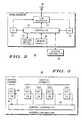
- FIG. 2illustrates a block diagram of a base station in the communication system of FIG. 1 .
- FIG. 3illustrates a block diagram of a system controller in the communication system of FIG. 1 .
- FIG. 4illustrates a flowchart of a method for providing communication services in accordance with the present invention.
- the present disclosurerelates to a communication system that provides communication services to communication devices over wireless channels.
- the communication systemincludes a resource controller that provides communication resources to various system components, including one or more base stations and system controllers.
- the communication devicescan subscribe to different classes of service priorities. For examples, some of the communication devices can be subscribed to a first class of service with higher service priorities, such as emergency services, and other communication devices, dependent upon for example, subscribed to a second class of service with lower service priorities, such as non-emergency services.
- the systemprovides communication service to all of the communication devices, irrespective of the service priority associated with a communication device.
- the systemprovides backup service in accordance with a class of service associated with the communication devices. For example, some but not all of the communication devices subscribed to a class of service can receive backup communication services.
- the systemprovides backup service to communication devices that are subscribed to a first class of service priority, but terminates service to communication devices that are subscribed to a second class of service priority.
- the communication devices that are subscribed to a higher service priorityfor example, communication devices belonging to an emergency fleet, receive communication service irrespective of a fault condition.
- the main system componentserves all of the communication devices, irrespective of service class, while the back system component can serve some but not all of the communication devices.
- the communication systemprovides communication service to communication devices that are subscribed to a lower service priority under normal operating conditions, but not all of such communication devices may receive backup communication service. Consequently, the backup system components can have a lower capacity relative to the main system components, thereby reducing system cost, enabling the system operators to offer communication services commensurate with class of service. System cost can be further reduced using a main system component of normal or moderate reliability and a lower capacity backup system component with high reliability.
- the main and backup system componentscan be any components that provides a system function.
- the main and backup system componentscan be base stations that provide wireless links between the system and the communication devices.
- the main and backup system componentscan be system controllers that control the operation of the base stations.
- the backup base stationserves emergency fleets, but does not serve non-emergency fleets and, when the main system controller fails to operate properly, the communication system switches to a backup system controller.
- FIG. 1a block diagram of a communication system 10 according to the present invention is shown.
- the communication system 10 of the exemplary embodimentis a trunked communication system offered by Motorola Inc., the assignee of the present invention.
- the system 10includes various system components, such as base stations, systems controllers, etc. The detailed specifics of the operation of trunked systems are well known. Therefore, the present invention is described herein only to the extent necessary for enabling one skilled in the art to make and use the invention.
- the description of the exemplary embodiment(s)relate to a trunked system, the present invention is equally applicable to various other wireless system embodiments, such as land mobile systems, cellular systems (e.g., GSM, IS-136, IS-95, iDen) personal communication systems (e.g., Bluetooth, GPRS, UMTS, G 2.0, etc.) and paging systems (e.g., Flex and Reflex).
- land mobile systemse.g., GSM, IS-136, IS-95, iDen
- personal communication systemse.g., Bluetooth, GPRS, UMTS, G 2.0, etc.
- paging systemse.g., Flex and Reflex
- the system 10provides communication services to a plurality of communication devices 12 .
- Each communication devices 12can operate as a single unit or it can operate in a group within an assigned fleet. As shown, some of the communication devices 12 belong to an emergency fleet, such as those associated with ambulances, etc., while others belong to non-emergency fleets.
- Each emergency fleet communication devicehas a service classification that provides a higher service priority relative to that offered to a non-emergency fleet communication device.
- a main base stations 14under the control of a main system controller 16 , provide RF links via an antenna 18 , to all of the communication devices, irrespective of service classification.
- the main system controller 16is responsible for the allocation of resources within the communication system 10 , including the allocation of the RF links or channels over which voice and control information are communicated.
- the main system controller 16is also responsible for interfacing with other communication networks, such as a public switching telephone network (PSTN) 17 .
- PSTNpublic switching telephone network
- a backup base station 20if the main base station 14 malfunctions or otherwise goes out of service, a backup base station 20 , possibly with a lower capacity than the main base station 14 , can serve some, but probably not all of the of the communication devices 12 , in accordance with a class of service to which the communication devices are subscribed to.
- the main system controller 16has an associated backup system controller 25 .
- the backup system controller 26may have a smaller capacity than that of the main system controller 14 .
- the backup system controller 26provides communication service to the communication devices 12 that subscribe to the first or higher class of service in the event of the main system controller 14 is out of service. As shown, switches 15 switch a main system component to a backup system component and vice versa.
- the backup station 20can only serve the communication devices 12 belonging to the higher priority emergency fleet, e.g., a police fleet or an ambulance fleet, etc. For example, in order to save costs, the backup station 20 may only support a fraction of the channels supported by the main base station 14 . Based on the lower priority associated with the non-emergency fleets, communication service to communication devices 12 belonging to these fleets are terminated. It should be noted that fleets or groups of the communication devices 12 can be divided into sub-fleets or sub-groups, each having an assigned class of service. Under the present invention, communication service to more than one class of service can be preserved or terminated when a main system component encounters a fault condition or otherwise goes out of service. Depending on the service capacity of the backup system controller 25 , service is terminated to those communication devices 12 that do not qualify for the first class of service.
- the main system controller 16 and the communication devices 12communicate control messages on a control channel and voice and data messages on a plurality of traffic channels. Based on control information received from the system controller 16 , the communication devices 18 use allocated traffic channels to carry voice an data communication.
- FIG. 2a general block diagram of a base station 22 is shown.
- the diagramis shown generally to encompass both the main or the backup base stations 16 and 20 of FIG. 1 , even though under the present invention, the main and backup base stations 16 and 20 can have different communication capacities, for example, in terms of number of supported RF channels, communication speed or required AC supply power, etc.
- the base station 22operates under the control of a base station controller 24 , which receives and responds to instructions or commands received from a system controller 26 .
- the controller 24executes a suitably developed application program that is stored in a memory 28 . Based on the received instructions from the system controller 26 , the controller 24 operates one or more transceivers supporting inbound and outbound traffic and control channels.
- controller 24applies modulation and amplification techniques for preparing a communication signal to be transmitted by a transmitter 32 over the outbound channels.
- the modulated amplified communication signalis then radiated via an antenna 36 through a TX/RX interface 34 that facilitates duplex communication under the control of the controller 24 .
- the antenna 36can be any one of an antenna known to those skilled in the art, for example, a monopole antenna.
- the base stationreceives electromagnetic radiation from the communication devices 12 at the antenna 36 over inbound communication channels. The received electromagnetic is demodulated at a receiver 30 which is coupled to the TR/RX interface 34 .
- the base station 22also includes failure detection circuitry 35 that upon detection of a failure transmits a failure signal to the controller 24 . Failure detection is known and will vary from device to device. Normally failure circuitry will be monitored in major functional area such as power supply, transmitter, receiver, etc., but has been depicted here as a separate entity for the sake of clarity.
- the controller 24in response to the failure signal, transmits an appropriate message to the system controller 26 , informing it of a system failure. As described in connection with FIG. 1 , once a failure condition is detected, the main system controller 16 switches from the main base station 14 to the backup base station 20 .
- the system controller 26can detect a fault condition on its own, for example, if a response to a polling request transmitted by the system controller is not received from the base station 22 within a predefined period of time.
- the system controller 26includes a central controller 38 that controls a plurality communication resources, such as inbound and outbound communication links to one or more base stations similar to the one described in FIG. 2 .
- the communication protocol on the control channelis predefined based on the requirement of the communication system 10 .
- the system controller 26allocates an outbound control channel 40 for transmission of outbound signaling words (OSW) in accordance with the communication protocol.
- the system controller 26also receives inbound signaling words (ISW) on an inbound control channel 42 .
- each OSWis 84 bits long and is transmitted at 3600 baud during a 23 ms time interval.
- Each ISWis 78 bits long also having a 3600 baud rate. Bit pattern of the ISWs and the OSWs are defined by the communication protocol requirements so as to communicate the control information that enables orderly communication with the communication devices 12 .
- the communication devices 12monitor the outbound control channel for background data OSWs that are periodically transmitted.
- the system controller 26also monitors the availability of other voice channels.
- the background OSWscontains such information as system identification and channel identification, which, among other things, inform the communication devices 12 of their fleets and channel assignments to that fleet.
- the OSWsalso provide synchronization among the communication devices 12 . Portions of the OSW bit stream are designated to provide both bit and word synchronization among the communication devices 12 and the main system controller 26 .
- communication devices 12When a call is initiated, communication devices 12 enter into transmit mode to transmit a channel access ISW.
- the communication devices 12transmit a first channel access ISW, on the inbound control channel.
- the channel access ISWcomprises information, such as fleet ID, unit ID, etc. Transmission of the first channel access ISW indicates that a communication device 12 is attempting to access service. If the system controller 26 receives the channel access request ISW, it searches all the available traffic channels and upon availability, allocates a traffic channel to the communication device 12 . If an available channel is found, a channel grant OSW is transmitted to the communication device 12 , and if an available channel is not found a channel busy OSW is transmitted. The channel grant OSW indicates the channel number of the allocated traffic channel to all of the communication devices 12 operating within the communication system 10 .
- the initiated callUpon reception of a valid OSW (i.e., channel grant or busy), the initiated call is processed.
- OSWi.e., channel grant or busy
- the initiated callis processed.
- all the communication devices 12 which have the same fleet or sub-fleet number as the originating communication device 12revert to the allocated traffic channel to carry on with the call.
- the communication devices 12are differentiated by an associated classes of service.
- the communication devices 12 that qualify for or subscribe to the first class of servicecan be emergency vehicles, for example, fire trucks, ambulances, and police cars.
- Such communication devices 12correspond to a high service priority relative to the second class of service.
- the second class of serviceis reserved for non-emergency services, for example; waste management systems, public transportation, and private infrastructures.
- Communication devices 12 that subscribe to the second class of serviceare subject to a low service priority. For example, in the event of faulty operating communications, devices 12 that subscribe to the first class of service continue normal communication, whereas the communication devices 12 that subscribe to the second class of service can and may experience communication failure.
- the system componentsdifferentiate between the classes of service to which the communication devices are subscribed.
- the communication devicesthemselves can inform the system of their class.
- the system componentcan retrieve subscription class information from a system database, such as an Home Location Register or a Visitor Location Register, which contains the services to which each communication device is subscribed.
- the componentmay store this information locally for ease of access. For example, a base station may maintain a copy of the information in local storage so that when parts of the system go down, the queries of the database that are needed to distinguish the different classes of communication devices do not create excessive network traffic.
- FIG. 4a flowchart for a method of servicing high priority communication devices 12 when the main base station 14 is out of service is shown.
- the main base station 14serves all of the communication devices 12 in the normal operating mode, block 410 .
- the backup base station 20is brought into and provides service to the communication devices 12 .
- the backup base station 20is limited to servicing communication devices 12 that subscribe to the first class of service. Therefore, at block 414 , service to communication devices 12 that subscribe to the second class of service is terminated or denied upon request.
- the present inventionprovides a method for providing reliable communication services to prioritized communication devices operating in a communication system. It would be further appreciated that the present invention provides a reliable communication service to communication devices at a reasonable cost by reducing the capacity and hardware in the backup infrastructure.
Landscapes
- Engineering & Computer Science (AREA)
- Computer Networks & Wireless Communication (AREA)
- Signal Processing (AREA)
- Telephonic Communication Services (AREA)
- Mobile Radio Communication Systems (AREA)
Abstract
Description
Claims (16)
Priority Applications (1)
| Application Number | Priority Date | Filing Date | Title |
|---|---|---|---|
| US09/650,118US6907237B1 (en) | 2000-08-28 | 2000-08-28 | Communication system that provides backup communication services to a plurality of communication devices |
Applications Claiming Priority (1)
| Application Number | Priority Date | Filing Date | Title |
|---|---|---|---|
| US09/650,118US6907237B1 (en) | 2000-08-28 | 2000-08-28 | Communication system that provides backup communication services to a plurality of communication devices |
Publications (1)
| Publication Number | Publication Date |
|---|---|
| US6907237B1true US6907237B1 (en) | 2005-06-14 |
Family
ID=34633087
Family Applications (1)
| Application Number | Title | Priority Date | Filing Date |
|---|---|---|---|
| US09/650,118Expired - LifetimeUS6907237B1 (en) | 2000-08-28 | 2000-08-28 | Communication system that provides backup communication services to a plurality of communication devices |
Country Status (1)
| Country | Link |
|---|---|
| US (1) | US6907237B1 (en) |
Cited By (42)
| Publication number | Priority date | Publication date | Assignee | Title |
|---|---|---|---|---|
| US20030035414A1 (en)* | 2001-08-20 | 2003-02-20 | Siemens Information | System and method for mixed mode public and private gatekeeper system |
| US20040102178A1 (en)* | 2002-11-15 | 2004-05-27 | John Williams | Emergency backup communications system |
| US20050037755A1 (en)* | 2002-10-30 | 2005-02-17 | Hugh Hind | Methods and apparatus for selecting a communication network |
| US20050198264A1 (en)* | 2004-01-29 | 2005-09-08 | Bekiares Tyrone D. | Dynamic selection of behavior sets for middleware |
| US20060235833A1 (en)* | 2005-04-19 | 2006-10-19 | Airsage, Inc. | Method and system for an integrated incident information and intelligence system |
| US20070225028A1 (en)* | 2006-03-23 | 2007-09-27 | Samsung Electronics Co., Ltd. | Adjacent-cell assisted redundancy for wireless communication networks |
| EP1898656A1 (en)* | 2006-09-06 | 2008-03-12 | Nokia Siemens Networks Gmbh & Co. Kg | Method for recovering connectivity in the event of a failure in a radio communications system and controlling node thereof |
| US20080284684A1 (en)* | 2007-05-17 | 2008-11-20 | Pioneer Corporation | Plasma display device and method for driving plasma display panel |
| EP2079274A2 (en) | 2008-01-10 | 2009-07-15 | NTT DoCoMo, Inc. | Radio base station, radio communication control system, and radio communication control method |
| US20090285090A1 (en)* | 2005-12-28 | 2009-11-19 | Andrea Allasia | Method and System for Providing User Access to Communication Services, and Related Computer Program Product |
| WO2010007412A1 (en) | 2008-07-15 | 2010-01-21 | Vodafone Group Plc | Emergency communications device |
| US7711393B1 (en)* | 2006-09-27 | 2010-05-04 | Nextel Communications Inc. | Cellular communications network optical cross-connect switching architecture |
| US8077600B2 (en)* | 2006-10-23 | 2011-12-13 | Fujitsu Limited | Mobile communication system |
| US20120057454A1 (en)* | 2010-09-02 | 2012-03-08 | Empire Technology Development Llc | Admission and Eviction Policies for Mobile Devices with Non-Telephonic Functionality |
| US20130253334A1 (en)* | 2012-02-09 | 2013-09-26 | Masimo Corporation | Wireless patient monitoring device |
| WO2014085067A1 (en)* | 2012-11-28 | 2014-06-05 | Motorola Solutions, Inc. | Incident aware service operations for wireless infrastructure |
| US20140358985A1 (en)* | 2013-05-30 | 2014-12-04 | Verizon Patent And Licensing Inc. | Failover for mobile devices |
| US9113831B2 (en) | 2002-03-25 | 2015-08-25 | Masimo Corporation | Physiological measurement communications adapter |
| US9161696B2 (en) | 2006-09-22 | 2015-10-20 | Masimo Corporation | Modular patient monitor |
| US9436645B2 (en) | 2011-10-13 | 2016-09-06 | Masimo Corporation | Medical monitoring hub |
| EP2548345A4 (en)* | 2010-03-16 | 2016-12-21 | Optimi Corp | Backup coverage in a wireless network |
| US9847002B2 (en) | 2009-12-21 | 2017-12-19 | Masimo Corporation | Modular patient monitor |
| US9943269B2 (en) | 2011-10-13 | 2018-04-17 | Masimo Corporation | System for displaying medical monitoring data |
| US10226187B2 (en) | 2015-08-31 | 2019-03-12 | Masimo Corporation | Patient-worn wireless physiological sensor |
| US10307111B2 (en) | 2012-02-09 | 2019-06-04 | Masimo Corporation | Patient position detection system |
| US10506508B2 (en)* | 2017-05-22 | 2019-12-10 | Indian Institute Of Technology Bombay | Highly available network architecture for a LTE based communication network |
| US10613789B1 (en)* | 2014-03-31 | 2020-04-07 | EMC IP Holding Company LLC | Analytics engine using consistent replication on distributed sites |
| US10617302B2 (en) | 2016-07-07 | 2020-04-14 | Masimo Corporation | Wearable pulse oximeter and respiration monitor |
| US10825568B2 (en) | 2013-10-11 | 2020-11-03 | Masimo Corporation | Alarm notification system |
| US10833983B2 (en) | 2012-09-20 | 2020-11-10 | Masimo Corporation | Intelligent medical escalation process |
| US10912524B2 (en) | 2006-09-22 | 2021-02-09 | Masimo Corporation | Modular patient monitor |
| US11076777B2 (en) | 2016-10-13 | 2021-08-03 | Masimo Corporation | Systems and methods for monitoring orientation to reduce pressure ulcer formation |
| US11109818B2 (en) | 2018-04-19 | 2021-09-07 | Masimo Corporation | Mobile patient alarm display |
| USD974193S1 (en) | 2020-07-27 | 2023-01-03 | Masimo Corporation | Wearable temperature measurement device |
| USD980091S1 (en) | 2020-07-27 | 2023-03-07 | Masimo Corporation | Wearable temperature measurement device |
| USD1000975S1 (en) | 2021-09-22 | 2023-10-10 | Masimo Corporation | Wearable temperature measurement device |
| US11963736B2 (en) | 2009-07-20 | 2024-04-23 | Masimo Corporation | Wireless patient monitoring system |
| US11974833B2 (en) | 2020-03-20 | 2024-05-07 | Masimo Corporation | Wearable device for noninvasive body temperature measurement |
| USD1048908S1 (en) | 2022-10-04 | 2024-10-29 | Masimo Corporation | Wearable sensor |
| US12257022B2 (en) | 2018-10-12 | 2025-03-25 | Masimo Corporation | System for transmission of sensor data using dual communication protocol |
| USD1072837S1 (en) | 2020-10-27 | 2025-04-29 | Masimo Corporation | Display screen or portion thereof with graphical user interface |
| US12440128B2 (en) | 2022-12-23 | 2025-10-14 | Masimo Corporation | Wrist and finger worn pulse oximetry system |
Citations (4)
| Publication number | Priority date | Publication date | Assignee | Title |
|---|---|---|---|---|
| US5742904A (en)* | 1996-07-08 | 1998-04-21 | Motorola, Inc. | Method of providing emergency alarm support via an alternative radio communication system |
| US6192232B1 (en)* | 1998-02-26 | 2001-02-20 | Fujitsu Limited | Emergency call control apparatus for mobile communication system |
| US6374099B1 (en)* | 1999-05-10 | 2002-04-16 | Lucent Technologies Inc. | High priority and/or emergency overload access control system |
| US6408182B1 (en)* | 1999-07-16 | 2002-06-18 | Ericsson, Inc. | Redundant mobile switching center (MSC) architecture for a radio telecommunications network |
- 2000
- 2000-08-28USUS09/650,118patent/US6907237B1/ennot_activeExpired - Lifetime
Patent Citations (4)
| Publication number | Priority date | Publication date | Assignee | Title |
|---|---|---|---|---|
| US5742904A (en)* | 1996-07-08 | 1998-04-21 | Motorola, Inc. | Method of providing emergency alarm support via an alternative radio communication system |
| US6192232B1 (en)* | 1998-02-26 | 2001-02-20 | Fujitsu Limited | Emergency call control apparatus for mobile communication system |
| US6374099B1 (en)* | 1999-05-10 | 2002-04-16 | Lucent Technologies Inc. | High priority and/or emergency overload access control system |
| US6408182B1 (en)* | 1999-07-16 | 2002-06-18 | Ericsson, Inc. | Redundant mobile switching center (MSC) architecture for a radio telecommunications network |
Cited By (108)
| Publication number | Priority date | Publication date | Assignee | Title |
|---|---|---|---|---|
| US20030035414A1 (en)* | 2001-08-20 | 2003-02-20 | Siemens Information | System and method for mixed mode public and private gatekeeper system |
| US11484205B2 (en) | 2002-03-25 | 2022-11-01 | Masimo Corporation | Physiological measurement device |
| US9788735B2 (en) | 2002-03-25 | 2017-10-17 | Masimo Corporation | Body worn mobile medical patient monitor |
| US9872623B2 (en) | 2002-03-25 | 2018-01-23 | Masimo Corporation | Arm mountable portable patient monitor |
| US10213108B2 (en) | 2002-03-25 | 2019-02-26 | Masimo Corporation | Arm mountable portable patient monitor |
| US10219706B2 (en) | 2002-03-25 | 2019-03-05 | Masimo Corporation | Physiological measurement device |
| US9113832B2 (en) | 2002-03-25 | 2015-08-25 | Masimo Corporation | Wrist-mounted physiological measurement device |
| US9113831B2 (en) | 2002-03-25 | 2015-08-25 | Masimo Corporation | Physiological measurement communications adapter |
| US10335033B2 (en) | 2002-03-25 | 2019-07-02 | Masimo Corporation | Physiological measurement device |
| US10869602B2 (en) | 2002-03-25 | 2020-12-22 | Masimo Corporation | Physiological measurement communications adapter |
| US9795300B2 (en) | 2002-03-25 | 2017-10-24 | Masimo Corporation | Wearable portable patient monitor |
| US8731552B2 (en) | 2002-10-30 | 2014-05-20 | Blackberry Limited | Methods and apparatus for selecting a communication network |
| US20050037755A1 (en)* | 2002-10-30 | 2005-02-17 | Hugh Hind | Methods and apparatus for selecting a communication network |
| US20060172737A1 (en)* | 2002-10-30 | 2006-08-03 | Research In Motion Limited | Methods and apparatus for selecting a communication network |
| US7184768B2 (en)* | 2002-10-30 | 2007-02-27 | Research In Motion Limited | Methods and apparatus for selecting a communication network |
| US7389109B2 (en) | 2002-10-30 | 2008-06-17 | Research In Motion Limited | Methods and apparatus for selecting a communication network |
| US8036654B2 (en) | 2002-10-30 | 2011-10-11 | Research In Motion Limited | Methods and apparatus for selecting a communication network |
| US20080287125A1 (en)* | 2002-10-30 | 2008-11-20 | Research In Motion Limited | Methods And Apparatus For Selecting A Communication Network |
| US20040102178A1 (en)* | 2002-11-15 | 2004-05-27 | John Williams | Emergency backup communications system |
| US20050198264A1 (en)* | 2004-01-29 | 2005-09-08 | Bekiares Tyrone D. | Dynamic selection of behavior sets for middleware |
| US8515565B2 (en)* | 2005-04-19 | 2013-08-20 | Airsage, Inc. | Method and system for an integrated incident information and intelligence system |
| US20060235833A1 (en)* | 2005-04-19 | 2006-10-19 | Airsage, Inc. | Method and system for an integrated incident information and intelligence system |
| US20090285090A1 (en)* | 2005-12-28 | 2009-11-19 | Andrea Allasia | Method and System for Providing User Access to Communication Services, and Related Computer Program Product |
| US8588076B2 (en)* | 2005-12-28 | 2013-11-19 | Telecom Italia S.P.A. | Method and system for providing user access to communication services, and related computer program product |
| US20070225028A1 (en)* | 2006-03-23 | 2007-09-27 | Samsung Electronics Co., Ltd. | Adjacent-cell assisted redundancy for wireless communication networks |
| US7583962B2 (en)* | 2006-03-23 | 2009-09-01 | Samsung Electronics Co., Ltd. | Adjacent-cell assisted redundancy for wireless communication networks |
| US20110045820A1 (en)* | 2006-09-06 | 2011-02-24 | Nokia Siemens Networks Gmbh & Co. Kg | Method for recovering connectivity in the event of a failure in a radio communications system and controlling node thereof |
| WO2008028916A1 (en)* | 2006-09-06 | 2008-03-13 | Nokia Siemens Networks Gmbh & Co. Kg | Method for recovering connectivity in the event of a failure in a radio communications system and controlling node thereof |
| EP1898656A1 (en)* | 2006-09-06 | 2008-03-12 | Nokia Siemens Networks Gmbh & Co. Kg | Method for recovering connectivity in the event of a failure in a radio communications system and controlling node thereof |
| US9161696B2 (en) | 2006-09-22 | 2015-10-20 | Masimo Corporation | Modular patient monitor |
| US10912524B2 (en) | 2006-09-22 | 2021-02-09 | Masimo Corporation | Modular patient monitor |
| US7711393B1 (en)* | 2006-09-27 | 2010-05-04 | Nextel Communications Inc. | Cellular communications network optical cross-connect switching architecture |
| US8077600B2 (en)* | 2006-10-23 | 2011-12-13 | Fujitsu Limited | Mobile communication system |
| US20080284684A1 (en)* | 2007-05-17 | 2008-11-20 | Pioneer Corporation | Plasma display device and method for driving plasma display panel |
| US8271041B2 (en) | 2008-01-10 | 2012-09-18 | Ntt Docomo, Inc. | Radio base station, radio communication control system, and radio communication control method |
| EP2079274A3 (en)* | 2008-01-10 | 2011-09-21 | NTT DoCoMo, Inc. | Radio base station, radio communication control system, and radio communication control method |
| US20090181677A1 (en)* | 2008-01-10 | 2009-07-16 | Ntt Docomo, Inc. | Radio base station, radio communication control system, and radio communication control method |
| EP2079274A2 (en) | 2008-01-10 | 2009-07-15 | NTT DoCoMo, Inc. | Radio base station, radio communication control system, and radio communication control method |
| GB2474216A (en)* | 2008-07-15 | 2011-04-06 | Vodafone Plc | Emergency communications device |
| WO2010007412A1 (en) | 2008-07-15 | 2010-01-21 | Vodafone Group Plc | Emergency communications device |
| US11963736B2 (en) | 2009-07-20 | 2024-04-23 | Masimo Corporation | Wireless patient monitoring system |
| US10354504B2 (en) | 2009-12-21 | 2019-07-16 | Masimo Corporation | Modular patient monitor |
| US9847002B2 (en) | 2009-12-21 | 2017-12-19 | Masimo Corporation | Modular patient monitor |
| US10943450B2 (en) | 2009-12-21 | 2021-03-09 | Masimo Corporation | Modular patient monitor |
| US11900775B2 (en) | 2009-12-21 | 2024-02-13 | Masimo Corporation | Modular patient monitor |
| EP2548345A4 (en)* | 2010-03-16 | 2016-12-21 | Optimi Corp | Backup coverage in a wireless network |
| US8660000B2 (en)* | 2010-09-02 | 2014-02-25 | Empire Technology Development Llc | Admission and eviction policies for mobile devices with non-telephonic functionality |
| US20120057454A1 (en)* | 2010-09-02 | 2012-03-08 | Empire Technology Development Llc | Admission and Eviction Policies for Mobile Devices with Non-Telephonic Functionality |
| US11241199B2 (en) | 2011-10-13 | 2022-02-08 | Masimo Corporation | System for displaying medical monitoring data |
| US10512436B2 (en) | 2011-10-13 | 2019-12-24 | Masimo Corporation | System for displaying medical monitoring data |
| US11179114B2 (en) | 2011-10-13 | 2021-11-23 | Masimo Corporation | Medical monitoring hub |
| US9436645B2 (en) | 2011-10-13 | 2016-09-06 | Masimo Corporation | Medical monitoring hub |
| US9993207B2 (en) | 2011-10-13 | 2018-06-12 | Masimo Corporation | Medical monitoring hub |
| US10925550B2 (en) | 2011-10-13 | 2021-02-23 | Masimo Corporation | Medical monitoring hub |
| US9913617B2 (en) | 2011-10-13 | 2018-03-13 | Masimo Corporation | Medical monitoring hub |
| US12329548B2 (en) | 2011-10-13 | 2025-06-17 | Masimo Corporation | Medical monitoring hub |
| US9943269B2 (en) | 2011-10-13 | 2018-04-17 | Masimo Corporation | System for displaying medical monitoring data |
| US11786183B2 (en) | 2011-10-13 | 2023-10-17 | Masimo Corporation | Medical monitoring hub |
| US12402843B2 (en) | 2011-10-13 | 2025-09-02 | Masimo Corporation | System for displaying medical monitoring data |
| US11918353B2 (en) | 2012-02-09 | 2024-03-05 | Masimo Corporation | Wireless patient monitoring device |
| US12109022B2 (en) | 2012-02-09 | 2024-10-08 | Masimo Corporation | Wireless patient monitoring device |
| US20130253334A1 (en)* | 2012-02-09 | 2013-09-26 | Masimo Corporation | Wireless patient monitoring device |
| US11083397B2 (en) | 2012-02-09 | 2021-08-10 | Masimo Corporation | Wireless patient monitoring device |
| US10188296B2 (en) | 2012-02-09 | 2019-01-29 | Masimo Corporation | Wireless patient monitoring device |
| US10307111B2 (en) | 2012-02-09 | 2019-06-04 | Masimo Corporation | Patient position detection system |
| USD788312S1 (en) | 2012-02-09 | 2017-05-30 | Masimo Corporation | Wireless patient monitoring device |
| US10149616B2 (en)* | 2012-02-09 | 2018-12-11 | Masimo Corporation | Wireless patient monitoring device |
| US11887728B2 (en) | 2012-09-20 | 2024-01-30 | Masimo Corporation | Intelligent medical escalation process |
| US10833983B2 (en) | 2012-09-20 | 2020-11-10 | Masimo Corporation | Intelligent medical escalation process |
| WO2014085067A1 (en)* | 2012-11-28 | 2014-06-05 | Motorola Solutions, Inc. | Incident aware service operations for wireless infrastructure |
| US9008607B2 (en) | 2012-11-28 | 2015-04-14 | Motorola Solutions, Inc. | Incident aware service operations for wireless infrastructure |
| US9848019B2 (en)* | 2013-05-30 | 2017-12-19 | Verizon Patent And Licensing Inc. | Failover for mobile devices |
| US20140358985A1 (en)* | 2013-05-30 | 2014-12-04 | Verizon Patent And Licensing Inc. | Failover for mobile devices |
| US12230396B2 (en) | 2013-10-11 | 2025-02-18 | Masimo Corporation | Alarm notification system |
| US10832818B2 (en) | 2013-10-11 | 2020-11-10 | Masimo Corporation | Alarm notification system |
| US10825568B2 (en) | 2013-10-11 | 2020-11-03 | Masimo Corporation | Alarm notification system |
| US11488711B2 (en) | 2013-10-11 | 2022-11-01 | Masimo Corporation | Alarm notification system |
| US12009098B2 (en) | 2013-10-11 | 2024-06-11 | Masimo Corporation | Alarm notification system |
| US11699526B2 (en) | 2013-10-11 | 2023-07-11 | Masimo Corporation | Alarm notification system |
| US10613789B1 (en)* | 2014-03-31 | 2020-04-07 | EMC IP Holding Company LLC | Analytics engine using consistent replication on distributed sites |
| US11576582B2 (en) | 2015-08-31 | 2023-02-14 | Masimo Corporation | Patient-worn wireless physiological sensor |
| US11089963B2 (en) | 2015-08-31 | 2021-08-17 | Masimo Corporation | Systems and methods for patient fall detection |
| US12133717B2 (en) | 2015-08-31 | 2024-11-05 | Masimo Corporation | Systems and methods for patient fall detection |
| US10736518B2 (en) | 2015-08-31 | 2020-08-11 | Masimo Corporation | Systems and methods to monitor repositioning of a patient |
| US10448844B2 (en) | 2015-08-31 | 2019-10-22 | Masimo Corporation | Systems and methods for patient fall detection |
| US10383527B2 (en) | 2015-08-31 | 2019-08-20 | Masimo Corporation | Wireless patient monitoring systems and methods |
| US12150739B2 (en) | 2015-08-31 | 2024-11-26 | Masimo Corporation | Systems and methods for patient fall detection |
| US10226187B2 (en) | 2015-08-31 | 2019-03-12 | Masimo Corporation | Patient-worn wireless physiological sensor |
| US11202571B2 (en) | 2016-07-07 | 2021-12-21 | Masimo Corporation | Wearable pulse oximeter and respiration monitor |
| US10617302B2 (en) | 2016-07-07 | 2020-04-14 | Masimo Corporation | Wearable pulse oximeter and respiration monitor |
| US12070293B2 (en) | 2016-07-07 | 2024-08-27 | Masimo Corporation | Wearable pulse oximeter and respiration monitor |
| US11076777B2 (en) | 2016-10-13 | 2021-08-03 | Masimo Corporation | Systems and methods for monitoring orientation to reduce pressure ulcer formation |
| US10506508B2 (en)* | 2017-05-22 | 2019-12-10 | Indian Institute Of Technology Bombay | Highly available network architecture for a LTE based communication network |
| US11109818B2 (en) | 2018-04-19 | 2021-09-07 | Masimo Corporation | Mobile patient alarm display |
| US11844634B2 (en) | 2018-04-19 | 2023-12-19 | Masimo Corporation | Mobile patient alarm display |
| US12193849B2 (en) | 2018-04-19 | 2025-01-14 | Masimo Corporation | Mobile patient alarm display |
| US12257022B2 (en) | 2018-10-12 | 2025-03-25 | Masimo Corporation | System for transmission of sensor data using dual communication protocol |
| US12364403B2 (en) | 2020-03-20 | 2025-07-22 | Masimo Corporation | Wearable device for noninvasive body temperature measurement |
| US11974833B2 (en) | 2020-03-20 | 2024-05-07 | Masimo Corporation | Wearable device for noninvasive body temperature measurement |
| USD974193S1 (en) | 2020-07-27 | 2023-01-03 | Masimo Corporation | Wearable temperature measurement device |
| USD980091S1 (en) | 2020-07-27 | 2023-03-07 | Masimo Corporation | Wearable temperature measurement device |
| USD1022729S1 (en) | 2020-07-27 | 2024-04-16 | Masimo Corporation | Wearable temperature measurement device |
| USD1072837S1 (en) | 2020-10-27 | 2025-04-29 | Masimo Corporation | Display screen or portion thereof with graphical user interface |
| US12440171B2 (en) | 2021-01-05 | 2025-10-14 | Masimo Corporation | Modular patient monitor |
| USD1050910S1 (en) | 2021-09-22 | 2024-11-12 | Masimo Corporation | Portion of a wearable temperature measurement device |
| USD1000975S1 (en) | 2021-09-22 | 2023-10-10 | Masimo Corporation | Wearable temperature measurement device |
| USD1048908S1 (en) | 2022-10-04 | 2024-10-29 | Masimo Corporation | Wearable sensor |
| US12440128B2 (en) | 2022-12-23 | 2025-10-14 | Masimo Corporation | Wrist and finger worn pulse oximetry system |
Similar Documents
| Publication | Publication Date | Title |
|---|---|---|
| US6907237B1 (en) | Communication system that provides backup communication services to a plurality of communication devices | |
| US5797097A (en) | Method and apparatus for identifying the location of a roaming pager | |
| US9357399B2 (en) | Mobile system and base station system for effectively using licensed spectrum and shared spectrum | |
| US6311060B1 (en) | Method and system for registering the location of a mobile cellular communications device | |
| CN1421106B (en) | Method for enabling mobile station to receive packet-switched pages | |
| US6577874B1 (en) | Methods and systems for providing temporary identification numbers for mobile terminals | |
| KR100795279B1 (en) | Car wireless relay system | |
| JP3524098B2 (en) | Collective calls in cellular radio systems | |
| AU2007269514B2 (en) | Method and system for communicating within a communication network | |
| US6804529B1 (en) | Trunked radio repeater communication system including home channel aliasing and call grouping | |
| US6745043B1 (en) | Priorty communication system and method of operation | |
| WO1998007286A2 (en) | In-band vehicular repeater for trunked radio system | |
| KR0127760B1 (en) | Single channel remote site trunking method and apparatus | |
| EP1362487B1 (en) | A communication system that provides adjustable communication service availability to subscribers | |
| CA2113281C (en) | A method and system for handling improper registrations | |
| CN102165804A (en) | Methods and apparatus for facilitating prevention of interference between base stations sharing carrier resources | |
| EP1049982B1 (en) | Messaging system for conditionally selecting a network | |
| US5649298A (en) | Method and apparatus of inter-operability between conventional and trunked communications system | |
| GB2287612A (en) | Communications system | |
| US5313654A (en) | Method for transferring a private call from a trunking communication system to a cellular communication system | |
| US5329574A (en) | Method for improving telephone resource access in a communication system network | |
| JP2002521986A (en) | Method, apparatus and system for operating a mobile telecommunications terminal in a public cellular mobile radio network | |
| US20040248616A1 (en) | Method for enabling receipt of a packet-switched page by a mobile station | |
| US9014696B1 (en) | System and method for priority wireless access | |
| JP2004007103A (en) | Base station and relay method |
Legal Events
| Date | Code | Title | Description |
|---|---|---|---|
| AS | Assignment | Owner name:MOTOROLA, INC., ILLINOIS Free format text:ASSIGNMENT OF ASSIGNORS INTEREST;ASSIGNORS:DORENBOSCH, JHEROEN P.;LOBO, LYNETTE J.;REEL/FRAME:011136/0549 Effective date:20000824 | |
| STCF | Information on status: patent grant | Free format text:PATENTED CASE | |
| FPAY | Fee payment | Year of fee payment:4 | |
| AS | Assignment | Owner name:MOTOROLA MOBILITY, INC, ILLINOIS Free format text:ASSIGNMENT OF ASSIGNORS INTEREST;ASSIGNOR:MOTOROLA, INC;REEL/FRAME:025673/0558 Effective date:20100731 | |
| AS | Assignment | Owner name:MOTOROLA MOBILITY LLC, ILLINOIS Free format text:CHANGE OF NAME;ASSIGNOR:MOTOROLA MOBILITY, INC.;REEL/FRAME:029216/0282 Effective date:20120622 | |
| FPAY | Fee payment | Year of fee payment:8 | |
| AS | Assignment | Owner name:GOOGLE TECHNOLOGY HOLDINGS LLC, CALIFORNIA Free format text:ASSIGNMENT OF ASSIGNORS INTEREST;ASSIGNOR:MOTOROLA MOBILITY LLC;REEL/FRAME:034488/0001 Effective date:20141028 | |
| FPAY | Fee payment | Year of fee payment:12 |