US6907163B2 - Multi-port optical coupling system - Google Patents
Multi-port optical coupling systemDownload PDFInfo
- Publication number
- US6907163B2 US6907163B2US10/227,315US22731502AUS6907163B2US 6907163 B2US6907163 B2US 6907163B2US 22731502 AUS22731502 AUS 22731502AUS 6907163 B2US6907163 B2US 6907163B2
- Authority
- US
- United States
- Prior art keywords
- collimator
- optical
- sleeve
- face
- angle
- Prior art date
- Legal status (The legal status is an assumption and is not a legal conclusion. Google has not performed a legal analysis and makes no representation as to the accuracy of the status listed.)
- Expired - Lifetime, expires
Links
- 230000003287optical effectEffects0.000titleclaimsabstractdescription134
- 230000008878couplingEffects0.000titleclaimsabstractdescription56
- 238000010168coupling processMethods0.000titleclaimsabstractdescription56
- 238000005859coupling reactionMethods0.000titleclaimsabstractdescription56
- 239000000835fiberSubstances0.000claimsdescription48
- 239000013307optical fiberSubstances0.000claimsdescription20
- 238000000034methodMethods0.000claimsdescription18
- 238000004519manufacturing processMethods0.000claimsdescription8
- 230000001902propagating effectEffects0.000claimsdescription3
- 239000011521glassSubstances0.000description9
- 239000004593EpoxySubstances0.000description3
- 230000005540biological transmissionEffects0.000description3
- 239000011248coating agentSubstances0.000description3
- 238000000576coating methodMethods0.000description3
- 238000004891communicationMethods0.000description3
- 238000013461designMethods0.000description3
- 238000013519translationMethods0.000description3
- 238000013459approachMethods0.000description2
- 230000000712assemblyEffects0.000description2
- 238000000429assemblyMethods0.000description2
- 230000000295complement effectEffects0.000description2
- 238000010276constructionMethods0.000description2
- 238000010586diagramMethods0.000description2
- 230000009977dual effectEffects0.000description2
- 210000001503jointAnatomy0.000description2
- 229910000679solderInorganic materials0.000description2
- 230000006978adaptationEffects0.000description1
- 238000010348incorporationMethods0.000description1
- 238000003780insertionMethods0.000description1
- 230000037431insertionEffects0.000description1
- 230000007246mechanismEffects0.000description1
- 239000002184metalSubstances0.000description1
- 238000012986modificationMethods0.000description1
- 230000004048modificationEffects0.000description1
- 238000010079rubber tappingMethods0.000description1
- 238000005549size reductionMethods0.000description1
- 238000012360testing methodMethods0.000description1
- 238000003466weldingMethods0.000description1
Images


Classifications
- G—PHYSICS
- G02—OPTICS
- G02B—OPTICAL ELEMENTS, SYSTEMS OR APPARATUS
- G02B6/00—Light guides; Structural details of arrangements comprising light guides and other optical elements, e.g. couplings
- G02B6/24—Coupling light guides
- G02B6/26—Optical coupling means
- G02B6/264—Optical coupling means with optical elements between opposed fibre ends which perform a function other than beam splitting
- G—PHYSICS
- G02—OPTICS
- G02B—OPTICAL ELEMENTS, SYSTEMS OR APPARATUS
- G02B6/00—Light guides; Structural details of arrangements comprising light guides and other optical elements, e.g. couplings
- G02B6/24—Coupling light guides
- G02B6/26—Optical coupling means
- G02B6/32—Optical coupling means having lens focusing means positioned between opposed fibre ends
- G02B6/327—Optical coupling means having lens focusing means positioned between opposed fibre ends with angled interfaces to reduce reflections
- G—PHYSICS
- G02—OPTICS
- G02B—OPTICAL ELEMENTS, SYSTEMS OR APPARATUS
- G02B6/00—Light guides; Structural details of arrangements comprising light guides and other optical elements, e.g. couplings
- G02B6/24—Coupling light guides
- G02B6/36—Mechanical coupling means
- G02B6/38—Mechanical coupling means having fibre to fibre mating means
- G02B6/3807—Dismountable connectors, i.e. comprising plugs
- G02B6/381—Dismountable connectors, i.e. comprising plugs of the ferrule type, e.g. fibre ends embedded in ferrules, connecting a pair of fibres
- G02B6/3825—Dismountable connectors, i.e. comprising plugs of the ferrule type, e.g. fibre ends embedded in ferrules, connecting a pair of fibres with an intermediate part, e.g. adapter, receptacle, linking two plugs
Definitions
- the present inventiongenerally relates to the field of optical couplers and in particular to multi-port coupling devices.
- Combining multiple optical functions in a single hybrid devicecan provide systems designers several advantages.
- Third, the number of fibers in a systemcan be reduced, again allowing module size reductions as well as minimizing the problems of fiber routing in system components.
- inventory managementis simplified by reducing the total parts count of an optical system.
- glass tubes and thin sections of epoxyhas been used to realize an epoxy-free optical path in passive fiber-optic components, while maintaining simplicity and low cost.
- This approachhas been realized in the use of three or four glass tubes to hold lenses, filters, and isolator cores in devices having up to three optical fiber ports.
- the deviceshave been constructed using tubes with perpendicular end faces, and which have been laterally translated to accomplish alignment perpendicular to the beam path, as well as sliding longitudinally to accomplish the focus alignment.
- Another object of this inventionis to provide an improved multi-port optical coupling device.
- an optical coupling systemcomprising a first collimator assembly having a first optical axis, a second collimator assembly having a second optical axis, an optical device disposed along an optical path between the first and the second collimator assembly, a first sleeve for containing the first collimator assembly, said first sleeve having an angled end face for forming a first angle; and a second sleeve for containing the second collimator assembly, said second sleeve having an end face for abutting the angled end face of the first sleeve such that the first optical axis of the first collimator assembly intersects with the second optical axis of the second collimator assembly at a coupling angle.
- the first sleeve and the second sleeveare relatively rotatable to each other for changing the coupling angle for coupling an optical signal between the first and the second collimator assembly.
- the end face of the second sleeveis angled for forming a second angle.
- the coupling angle between the first optical axis and the second optical axisis smaller or substantially equal to a sum of the first angle and the second angle.
- the optical devicecomprises at least one of a tap coupler, an isolator and a WDM filter.
- the first collimator assemblycomprises a first collimating lens supported in a first lens sleeve and a first fiber tube containing at least one optical fiber supported in a first fiber tube sleeve and wherein the second collimator assembly comprises a second collimating lens supported in a second lens sleeve and a second fiber tube containing at least one optical fiber supported in a second fiber tube sleeve.
- the collimating lensis a GRIN lens.
- an optical coupler devicecomprising a first collimator having a first optical axis, said first collimator comprising an input optical fiber tube having at least two optical fibers therein and an input lens, a second collimator having a second optical axis, said second collimator comprising an output optical fiber tube having at least two optical fibers therein and an output lens, said first collimator and said second collimator are optically aligned with each other, an optical device disposed along an optical path between the first collimator and the second collimator, a first outer sleeve for containing the first collimator, said first sleeve having an angled end face for forming a first angle, and a second outer sleeve for containing the second collimator, said second sleeve having an angled end face for abutting to the angled end face of the first sleeve such that the first optical axis intersects with the second optical axis at a coup
- the first outer sleeve and the second outer sleeveare relatively rotatable to each other for changing the coupling angle for coupling an optical signal between the first and the second collimator.
- the coupling angle between the first optical axis and the second optical axisranges from a difference to a sum of the first angle and the second angle.
- the tap coupleris disposed at an end face of the input lens for reflecting at least a portion of an optical signal propagating through said optical coupler device.
- the optical coupler devicefurther comprises a filter retaining sleeve for retaining the WDM filter, wherein the filter retaining sleeve retains at least a portion of the output lens.
- the isolatorcomprises a magnet and two isolator cores disposed at an end face of the input lens, wherein said magnet retains at least a portion of the input lens.
- an outer diameter of the input or output sleeveis larger than an outer diameter of the input or output fiber tube sleeve.
- a method of making an optical coupler devicecomprising the steps of making a first collimator subassembly, making a second collimator subassembly, sliding a first outer sleeve having an angled end face over the first collimator subassembly, sliding a second outer sleeve having an angled end face over the second collimator subassembly, abutting the angled end faces of the first and second outer sleeves, aligning the first and the second collimator subassemblies for providing an optical path between the first and the second collimator subassembly so that an image of an input fiber is coincident with a core of an output fiber, relatively translating the first and the second outer sleeves for accommodating an off-set of the optical path, relatively rotating the first and the second outer sleeve without rotating the first and second collimator subassemblies, for imparting a tilt for aligning the optical path; and fastening
- the methodfurther comprises the step of fastening at last one of a tap coupler, an isolator, and a WDM filter between the first and the second collimator subassembly.
- the present inventionprovides an optical coupling device and a method of making such an optical coupling device wherein rotatable wedges, such as the outer sleeves having an angled end face, are used to compensate for an angle between two collimator subassemblies.
- FIG. 1shows a schematic functional diagram of an Isolator-Tap-Multiplexer optical coupling device
- FIG. 2 ais a schematic view of two outer sleeves having complementary slanted end faces oriented such that the optical axes of the sleeves and components therein are coincident forming 180 degree angle therebetween.
- FIG. 2 bis a schematic view of the same sleeves shown in FIG. 2 a , wherein the sleeves are relatively rotated such that their optical axes intersect at an angle of 178 degrees; it is noted that a bend is defined where the two sleeves join.
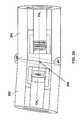
- FIG. 3shows a cross-sectional view of a 4-port hybrid coupling device.
- the present inventionprovides a method and an apparatus for an optical coupling device.
- an optical coupling device and a method of making such an optical coupling device with more than three portsis described.
- the present inventionincludes a passive four-port hybrid device, called an Isolator-Tap-Multiplexer, and a technique for its fabrication.
- the fabrication techniquecan be extended to apply to multiple hybrid device designs of similar complexity. Due to the mechanical simplicity of the hybrid design proposed, it is expected that the reliability of devices made using this technique can approach that of single function devices.
- FIG. 1a schematic functional diagram of an Isolator-Tap-Multiplexer optical coupling device 100 is shown.
- the isolatoris realized between Ports 1 and 3, while Ports 1 and 2 are connected as an optical tap, with a small amount of the optical signal diverted from Port 1 into Port 2.
- Ports 4 and 3are connected as a pump multiplexer path, wherein a laser pump signal is combined with the output signal path of port 3.
- Port 1 - Port 2Optical Tap Port 1 -> Port 3 Low loss connection (c-band) Port 3 -> Port 1 High loss (isolator) Port 4 - Port 3 Low loss connection (pump wavelength) Port 1 - Port 4 No Connection
- the tap and the multiplexer branch subassembliesare first fabricated separately.
- the isolator coresare then attached to one of these branches, and the two subassemblies are then optically aligned. They are then affixed in inner glass sleeves.
- optical signalsare transmitted through optical fibers.
- To monitor the signal level or the conditions of the transmissionit is often necessary to tap a small amount of light from the main line.
- the conventional scheme for tappingis achieved by inserting an optical coating film in the main optical path.
- the coating filmwill reflect a small amount of the light being transmitted in the forward direction in the main path, while leaving most of the light transmitted in the main path for communication purposes. This small amount of light that is reflected by the optical coating film is then collected and analyzed in order to monitor the signal level or the conditions of transmission of the optical communication line.
- two outer sleeves having an angled end faceare fabricated.
- the outer sleevesare slid over the subassemblies and the subassemblies are aligned within the outer sleeves.
- the axes of the outer sleeveswill make an angle with each other ranging from the difference between the end face angles to their sum.
- FIG. 2 ashows a schematic view of two outer sleeves 202 , 204 in accordance with an embodiment of the present invention.
- the two outer sleeveshave complementary angled end faces so that when they are mated at these angled end faces, as shown at 206 , the axes of the tubes can make an angle of up to the sum of the end face angles.
- the optical axes of the two sleevesare coincident, or 180 degrees with respect to each other.
- the same sleevesare relatively rotated so such that their optical axes OA 1 and OA 2 intersect at an angle of less than 180 degrees thereby forming a bend between the two sleeves, wherein their optical axes intersect.
- FIGS. 2 a and 2 bThis provides a simple mechanism for varying the angle of the optical axes between respective lenses housed by the two outer sleeves.
- the components shown in FIGS. 2 a and 2 bwill be described in more detail in FIG. 3 .
- input and output optical fibersare not shown in FIGS. 2 a and 2 b.
- FIG. 3shows an optical coupling device in accordance with an embodiment of the present invention presenting a cross-sectional view of a 4-port hybrid coupling device 300 .
- Optical coupling system 300comprises a tap coupler 302 , a dual stage isolator 304 , and a WDM pump/signal combiner 306 .
- Lightis incident on the device from one of the two fibers contained in the input fiber tube 308 .
- the incoming lightis collimated by input GRIN lens 310 , and is partially reflected at the left surface of this lens by tap coupler 302 .
- the reflectionis coupled into the other fiber held in the input fiber tube 308 . This produces the tap coupler function of the device.
- the remainder of the light that has not been reflected by this surfaceis then transmitted through the dual isolator core 304 , and is transmitted through WDM filter 306 .
- This lightis then focused by output lens 312 onto one of the fibers in the output fiber tube 314 . This constitutes the isolator function of the device.
- Pump laser light entering the device on the other fiber in the output fiber tube 314is collimated by output lens 312 , reflected by WDM filter 306 , and is then focused onto the output fiber, realizing the WDM pump multiplexer.
- This deviceis fabricated by first assembling an input collimator by assembling the input fiber tube 308 and the input lens 310 using a standard glass sleeve technique.
- the input lens 310 and the input fiber tube 308are each inserted into a glass sleeve, i.e. an input lens sleeve 318 and an input fiber tube sleeve 316 , and are aligned by translating them with respect to each other until the light from the reflection at the far surface of the lens 310 is coupled from one fiber to the other.
- the sleeves 318 and 316are then bonded to the lens 310 and fiber tube 308 and then to each other using hot-wicked epoxy or another bonding technique.
- the output collimatoris fabricated by first assembling the output fiber tube 314 and the output lens 312 using the standard glass sleeve technique.
- the output lens 312 and the output fiber tube 314are each inserted into a glass sleeve, i.e. an output lens sleeve 320 and an output fiber tube sleeve 322 , and are aligned by translating them with respect to each other.
- the sleeves 320 and 322are then bonded to the lens 312 and fiber tube 314 and then to each other using hot-wicked epoxy or another bonding technique.
- the input and output lensesare GRIN lenses.
- other collimating lensescan be used.
- the outer diameter of the lens sleeves 318 , 320are larger than the outer diameter of the fiber tube sleeves 316 , 322 so that outer sleeves 324 , 326 can slide freely on the respective lens sleeves 320 , 318 .
- the isolator core assembly 304consisting of a magnet 328 and two isolator cores 304 , is then bonded to the lens 310 to complete the first subassembly.
- the WDM filter 306is mounted onto the output lens 312 .
- Thisis shown to be done using a mechanical spring mounting since this presents a robust technique with respect to damp heat testing.
- the inventionis not intended to be limited to this mounting technique and other ways of mounting the WDM filter 306 to lens 312 are intended to be included.
- the output fiber tube 322is then mounted in the same way as the input fiber tube, coupling light reflected by the filter from one fiber to the other. This yields two subassemblies, each with a reflective path coupled between its two fibers.
- An outer sleeve 324 , 326 having a angled end faceis then slid over the lens sleeves 320 , 318 in each subassembly.
- the two subassembliesare aligned with respect to each other so as to couple light from one fiber in the input fiber tube 308 into one of the fibers in the output fiber tube 314 .
- the two outer sleeves 324 , 326are then slid toward each other until they make contact, and then rotated until the two angled end faces mate with each other with the two angled surfaces flush with each other, as shown in FIG. 2 .
- the outer sleeves 324 , 326are then bonded to their respective lens sleeves 320 , 318 and are then bonded to each other at the central butt joint.
- the use of rotatable wedged tubes, such as the two outer sleeves 324 , 326 , as shown in FIGS. 2-3is used to compensate for the inevitable angle between the two collimator assemblies.
- the distance between the collimating lensesis not critical because the light beam propagating between the two collimator subassemblies is collimated.
- only one of the outer sleeveshas an angled end face.
- the outer sleeve and the collimator subassembly within that outer sleeveis rotated to achieve the necessary two degrees of freedom for aligning the optical coupling system.
- the rotation of the outer sleevesis performed to obtain two substantially parallel planar surfaces, i.e. the end faces of the outer sleeves are substantially parallel when the alignment of the optical coupling system is optimized.
- optical coupling system and the method of making an optical coupling system in accordance with the present inventionis capable of aligning and fixing two parts in angle and translation, unlike a pure translation currently employed in prior art assemblies.
- optical coupling system and the method of making an optical coupling system in accordance with the present inventionis capable of aligning and fixing two parts in angle and translation, unlike a pure translation currently employed in prior art assemblies.
- only zero thickness bondsare required, unlike a space-filling solder technique, for example.
- the outer sleeves 324 , 326are made of glass.
- the outer sleevescan be made of metal if the apparatus and method of the invention are adapted to devices fabricated with laser welding or any other technique that is incapable of space-filling.
Landscapes
- Physics & Mathematics (AREA)
- General Physics & Mathematics (AREA)
- Optics & Photonics (AREA)
- Optical Couplings Of Light Guides (AREA)
Abstract
Description
| Path | Connection | ||
| Port 1 - | Optical Tap | ||
| Port 1 -> | Low loss connection (c-band) | ||
| Port 3 -> | High loss (isolator) | ||
| Port 4 - | Low loss connection (pump wavelength) | ||
| Port 1 - | No Connection | ||
Claims (20)
Priority Applications (1)
| Application Number | Priority Date | Filing Date | Title |
|---|---|---|---|
| US10/227,315US6907163B2 (en) | 2001-08-27 | 2002-08-26 | Multi-port optical coupling system |
Applications Claiming Priority (2)
| Application Number | Priority Date | Filing Date | Title |
|---|---|---|---|
| US31462601P | 2001-08-27 | 2001-08-27 | |
| US10/227,315US6907163B2 (en) | 2001-08-27 | 2002-08-26 | Multi-port optical coupling system |
Publications (2)
| Publication Number | Publication Date |
|---|---|
| US20030044115A1 US20030044115A1 (en) | 2003-03-06 |
| US6907163B2true US6907163B2 (en) | 2005-06-14 |
Family
ID=26921351
Family Applications (1)
| Application Number | Title | Priority Date | Filing Date |
|---|---|---|---|
| US10/227,315Expired - LifetimeUS6907163B2 (en) | 2001-08-27 | 2002-08-26 | Multi-port optical coupling system |
Country Status (1)
| Country | Link |
|---|---|
| US (1) | US6907163B2 (en) |
Cited By (15)
| Publication number | Priority date | Publication date | Assignee | Title |
|---|---|---|---|---|
| US20050008292A1 (en)* | 2003-07-10 | 2005-01-13 | Zeqin Wang | Wavelength division multiplexed coupler |
| US20070116408A1 (en)* | 2005-11-22 | 2007-05-24 | Eberle Michael J | Optical imaging probe connector |
| US20090059727A1 (en)* | 2002-10-07 | 2009-03-05 | Vascular Imaging Corporation | Systems and methods for minimally-invasive optical-acoustic imaging |
| US20090135429A1 (en)* | 2007-11-28 | 2009-05-28 | Fujifilm Corporation | Optical connector and an optical tomographic imaging system using the same |
| US20100087732A1 (en)* | 2008-10-02 | 2010-04-08 | Vascular Imaging Corporation | Optical ultrasound receiver |
| US8873134B2 (en) | 2008-08-21 | 2014-10-28 | Nlight Photonics Corporation | Hybrid laser amplifier system including active taper |
| US8873909B1 (en)* | 2012-04-23 | 2014-10-28 | Alliance Fiber Optic Products, Inc. | Micro-optic filtering devices and method of making the same |
| US8926519B2 (en) | 1998-03-05 | 2015-01-06 | Vascular Imaging Corporation | Opitcal-acoustic imaging device |
| US9063289B1 (en) | 2008-06-30 | 2015-06-23 | Nlight Photonics Corporation | Multimode fiber combiners |
| US9158070B2 (en) | 2008-08-21 | 2015-10-13 | Nlight Photonics Corporation | Active tapers with reduced nonlinearity |
| US9285541B2 (en) | 2008-08-21 | 2016-03-15 | Nlight Photonics Corporation | UV-green converting fiber laser using active tapers |
| US9356418B2 (en) | 2012-12-31 | 2016-05-31 | Nlight, Inc. | All fiber low dynamic pointing high power LMA fiber amplifier |
| US9484707B2 (en) | 2012-12-31 | 2016-11-01 | Nlight, Inc. | Spatially stable high brightness fiber |
| US9484706B1 (en) | 2012-06-12 | 2016-11-01 | Nlight, Inc. | Tapered core fiber manufacturing methods |
| US9494738B1 (en) | 2009-05-28 | 2016-11-15 | Nlight, Inc. | Single mode fiber combiners |
Families Citing this family (4)
| Publication number | Priority date | Publication date | Assignee | Title |
|---|---|---|---|---|
| US9090315B1 (en)* | 2010-11-23 | 2015-07-28 | Piedra—Sombra Corporation, Inc. | Optical energy transfer and conversion system |
| CN114730174A (en) | 2019-11-19 | 2022-07-08 | 三菱电机株式会社 | Information processing apparatus, control method, control program, and information providing system |
| CN112068254A (en)* | 2020-09-21 | 2020-12-11 | 江西麦帝施科技有限公司 | Optical fiber coupler |
| CN115308852A (en)* | 2022-07-20 | 2022-11-08 | 昂纳信息技术(深圳)有限公司 | An optical module and its receiving end assembly |
Citations (14)
| Publication number | Priority date | Publication date | Assignee | Title |
|---|---|---|---|---|
| US4926430A (en)* | 1988-11-18 | 1990-05-15 | Fujitsu Limited | Laser module with a built-in optical isolator, and method of adjusting the angular position of the optical isolator |
| JPH05113520A (en)* | 1991-10-23 | 1993-05-07 | Fujitsu Ltd | Joining unit for optical components |
| US5555330A (en) | 1994-12-21 | 1996-09-10 | E-Tek Dynamics, Inc. | Wavelength division multiplexed coupler with low crosstalk between channels and integrated coupler/isolator device |
| US6198858B1 (en) | 1994-12-21 | 2001-03-06 | E-Tek Dynamics, Inc. | Integrable fiberoptic coupler and resulting devices and systems |
| US6215924B1 (en) | 1998-08-06 | 2001-04-10 | Optical Coating Laboratory, Inc. | Optical coupler device for dense wavelength division multiplexing |
| US6282339B1 (en) | 1999-05-10 | 2001-08-28 | Jds Uniphase Inc. | Reliable low-cost wavelength division multiplexed coupler with flexible and precise optical path adjustment |
| US6292604B1 (en) | 1999-07-16 | 2001-09-18 | Jds Fitel Inc. | Optical coupler arrangement |
| US20020006252A1 (en) | 2000-06-02 | 2002-01-17 | Im Young-Min | Tap coupler |
| US6393179B1 (en) | 1997-07-18 | 2002-05-21 | Jds Fitel Inc. | Optical coupling system |
| US6404954B1 (en) | 2000-08-31 | 2002-06-11 | Oplink Communications, Inc. | Angled-axis fiber-optic couplers |
| US20020071182A1 (en)* | 2000-12-12 | 2002-06-13 | New Focus, Inc. | Dual-stage optical isolator minimized polarization mode dispersion and simplified fabrication process |
| US6599023B2 (en)* | 2001-07-10 | 2003-07-29 | Hon Hai Precision Ind. Co., Ltd. | Optical isolator |
| US20030185519A1 (en)* | 2002-04-02 | 2003-10-02 | Michael Ushinsky | Articulated enclosure for optical packages and method of manufacture |
| US6702476B2 (en)* | 2002-05-02 | 2004-03-09 | Agere Systems Inc. | Optical fiber device having attachment to optical device package |
Family Cites Families (12)
| Publication number | Priority date | Publication date | Assignee | Title |
|---|---|---|---|---|
| US2366152A (en)* | 1943-01-13 | 1944-12-26 | Lauterbach George Edward | System and apparatus for detecting high and wide railroad cars and open top lading |
| US3419847A (en)* | 1966-01-28 | 1968-12-31 | Robert S. Bonney | Low bridge warning device for vehicles |
| SE344386B (en)* | 1968-04-17 | 1972-04-10 | Hitachi Ltd | |
| US3716863A (en)* | 1970-08-06 | 1973-02-13 | American Nucleonics Corp | Instrument landing error correcting system |
| US3896414A (en)* | 1973-07-11 | 1975-07-22 | Charles J Rulo | Roadway detour system for vehicles |
| US4284971A (en)* | 1979-04-02 | 1981-08-18 | Lowry Elliot G | Overheight vehicle detection and warning system |
| US4916429A (en)* | 1989-05-19 | 1990-04-10 | Hicks Earl G | Overheight detector system for drive through restaurant |
| JPH0554276A (en)* | 1991-08-23 | 1993-03-05 | Matsushita Electric Ind Co Ltd | Obstacle detection device |
| JPH05225490A (en)* | 1992-02-07 | 1993-09-03 | Toshiba Corp | Vehicle type identification device |
| US5546188A (en)* | 1992-11-23 | 1996-08-13 | Schwartz Electro-Optics, Inc. | Intelligent vehicle highway system sensor and method |
| US5793491A (en)* | 1992-12-30 | 1998-08-11 | Schwartz Electro-Optics, Inc. | Intelligent vehicle highway system multi-lane sensor and method |
| US6195019B1 (en)* | 1998-01-20 | 2001-02-27 | Denso Corporation | Vehicle classifying apparatus and a toll system |
- 2002
- 2002-08-26USUS10/227,315patent/US6907163B2/ennot_activeExpired - Lifetime
Patent Citations (14)
| Publication number | Priority date | Publication date | Assignee | Title |
|---|---|---|---|---|
| US4926430A (en)* | 1988-11-18 | 1990-05-15 | Fujitsu Limited | Laser module with a built-in optical isolator, and method of adjusting the angular position of the optical isolator |
| JPH05113520A (en)* | 1991-10-23 | 1993-05-07 | Fujitsu Ltd | Joining unit for optical components |
| US5555330A (en) | 1994-12-21 | 1996-09-10 | E-Tek Dynamics, Inc. | Wavelength division multiplexed coupler with low crosstalk between channels and integrated coupler/isolator device |
| US6198858B1 (en) | 1994-12-21 | 2001-03-06 | E-Tek Dynamics, Inc. | Integrable fiberoptic coupler and resulting devices and systems |
| US6393179B1 (en) | 1997-07-18 | 2002-05-21 | Jds Fitel Inc. | Optical coupling system |
| US6215924B1 (en) | 1998-08-06 | 2001-04-10 | Optical Coating Laboratory, Inc. | Optical coupler device for dense wavelength division multiplexing |
| US6282339B1 (en) | 1999-05-10 | 2001-08-28 | Jds Uniphase Inc. | Reliable low-cost wavelength division multiplexed coupler with flexible and precise optical path adjustment |
| US6292604B1 (en) | 1999-07-16 | 2001-09-18 | Jds Fitel Inc. | Optical coupler arrangement |
| US20020006252A1 (en) | 2000-06-02 | 2002-01-17 | Im Young-Min | Tap coupler |
| US6404954B1 (en) | 2000-08-31 | 2002-06-11 | Oplink Communications, Inc. | Angled-axis fiber-optic couplers |
| US20020071182A1 (en)* | 2000-12-12 | 2002-06-13 | New Focus, Inc. | Dual-stage optical isolator minimized polarization mode dispersion and simplified fabrication process |
| US6599023B2 (en)* | 2001-07-10 | 2003-07-29 | Hon Hai Precision Ind. Co., Ltd. | Optical isolator |
| US20030185519A1 (en)* | 2002-04-02 | 2003-10-02 | Michael Ushinsky | Articulated enclosure for optical packages and method of manufacture |
| US6702476B2 (en)* | 2002-05-02 | 2004-03-09 | Agere Systems Inc. | Optical fiber device having attachment to optical device package |
Cited By (38)
| Publication number | Priority date | Publication date | Assignee | Title |
|---|---|---|---|---|
| US9532766B2 (en) | 1998-03-05 | 2017-01-03 | Vascular Imaging Corporation | Optical-acoustic imaging device |
| US8926519B2 (en) | 1998-03-05 | 2015-01-06 | Vascular Imaging Corporation | Opitcal-acoustic imaging device |
| US8059923B2 (en) | 2002-10-07 | 2011-11-15 | Vascular Imaging Corporation | Systems and methods for minimally-invasive optical-acoustic imaging |
| US20090059727A1 (en)* | 2002-10-07 | 2009-03-05 | Vascular Imaging Corporation | Systems and methods for minimally-invasive optical-acoustic imaging |
| US9339192B2 (en) | 2002-10-07 | 2016-05-17 | Vascular Imaging Corporation | Systems and methods for minimally-invasive optical-acoustic imaging |
| US9192307B2 (en) | 2002-10-07 | 2015-11-24 | Vascular Imaging Corporation | Systems and methods for minimally-invasive optical-acoustic imaging |
| US7660492B2 (en) | 2002-10-07 | 2010-02-09 | Vascular Imaging Corporation | Systems and methods for minimally-invasive optical-acoustic imaging |
| US20100135111A1 (en)* | 2002-10-07 | 2010-06-03 | Vascular Imaging Corporation | Systems and methods for minimally-invasive optical-acoustic imaging |
| US8731340B2 (en) | 2002-10-07 | 2014-05-20 | Vascular Imaging Corporation | Systems and methods for minimally-invasive optical-acoustic imaging |
| US8391652B2 (en) | 2002-10-07 | 2013-03-05 | Vascular Imaging Corporation | Systems and methods for minimally-invasive optical-acoustic imaging |
| US7440652B2 (en)* | 2003-07-10 | 2008-10-21 | O-Net Communication (Sz) Ltd. | Wavelength division multiplexed coupler |
| US20050008292A1 (en)* | 2003-07-10 | 2005-01-13 | Zeqin Wang | Wavelength division multiplexed coupler |
| US8861908B2 (en) | 2005-11-22 | 2014-10-14 | Vascular Imaging Corporation | Optical imaging probe |
| US7599588B2 (en)* | 2005-11-22 | 2009-10-06 | Vascular Imaging Corporation | Optical imaging probe connector |
| US8320723B2 (en) | 2005-11-22 | 2012-11-27 | Vascular Imaging Corporation | Optical imaging probe connector |
| US9557490B2 (en) | 2005-11-22 | 2017-01-31 | Vascular Imaging Corporation | Optical imaging probe |
| US7881573B2 (en) | 2005-11-22 | 2011-02-01 | Vascular Imaging Corporation | Optical imaging probe connector |
| US20070116408A1 (en)* | 2005-11-22 | 2007-05-24 | Eberle Michael J | Optical imaging probe connector |
| US20110123154A1 (en)* | 2005-11-22 | 2011-05-26 | Vascular Imaging Corporation | Optical imaging probe connector |
| US20100014810A1 (en)* | 2005-11-22 | 2010-01-21 | Vascular Imaging Corporation | Optical imaging probe connector |
| US9198581B2 (en) | 2005-11-22 | 2015-12-01 | Vascular Imaging Corporation | Optical imaging probe |
| US7940397B2 (en)* | 2007-11-28 | 2011-05-10 | Fujifilm Corporation | Optical connector and an optical tomographic imaging system using the same |
| US20090135429A1 (en)* | 2007-11-28 | 2009-05-28 | Fujifilm Corporation | Optical connector and an optical tomographic imaging system using the same |
| US9535217B1 (en) | 2008-06-30 | 2017-01-03 | Nlight, Inc. | Multimode fiber combiners |
| US9063289B1 (en) | 2008-06-30 | 2015-06-23 | Nlight Photonics Corporation | Multimode fiber combiners |
| US8873134B2 (en) | 2008-08-21 | 2014-10-28 | Nlight Photonics Corporation | Hybrid laser amplifier system including active taper |
| US9158070B2 (en) | 2008-08-21 | 2015-10-13 | Nlight Photonics Corporation | Active tapers with reduced nonlinearity |
| US9285541B2 (en) | 2008-08-21 | 2016-03-15 | Nlight Photonics Corporation | UV-green converting fiber laser using active tapers |
| US9078561B2 (en) | 2008-10-02 | 2015-07-14 | Vascular Imaging Corporation | Optical ultrasound receiver |
| US20100087732A1 (en)* | 2008-10-02 | 2010-04-08 | Vascular Imaging Corporation | Optical ultrasound receiver |
| US8560048B2 (en) | 2008-10-02 | 2013-10-15 | Vascular Imaging Corporation | Optical ultrasound receiver |
| US9579026B2 (en) | 2008-10-02 | 2017-02-28 | Vascular Imaging Corporation | Optical ultrasound receiver |
| US9494738B1 (en) | 2009-05-28 | 2016-11-15 | Nlight, Inc. | Single mode fiber combiners |
| US8873909B1 (en)* | 2012-04-23 | 2014-10-28 | Alliance Fiber Optic Products, Inc. | Micro-optic filtering devices and method of making the same |
| US9484706B1 (en) | 2012-06-12 | 2016-11-01 | Nlight, Inc. | Tapered core fiber manufacturing methods |
| US9815731B1 (en) | 2012-06-12 | 2017-11-14 | Nlight, Inc. | Tapered core fiber manufacturing methods |
| US9356418B2 (en) | 2012-12-31 | 2016-05-31 | Nlight, Inc. | All fiber low dynamic pointing high power LMA fiber amplifier |
| US9484707B2 (en) | 2012-12-31 | 2016-11-01 | Nlight, Inc. | Spatially stable high brightness fiber |
Also Published As
| Publication number | Publication date |
|---|---|
| US20030044115A1 (en) | 2003-03-06 |
Similar Documents
| Publication | Publication Date | Title |
|---|---|---|
| US6907163B2 (en) | Multi-port optical coupling system | |
| US6498876B1 (en) | Multi-port fiber optic device with v-groove ferrule | |
| US5675683A (en) | Optical coupler constructed using optical fiber ferrules | |
| WO2017118271A1 (en) | Parallel transmission and reception optical module for dual-link transmission, and preparation method | |
| US20030063853A1 (en) | Wavelength division multiplexed coupler | |
| KR20040015329A (en) | Hybrid fiber expanded beam connector and methods for using and making the hybrid fiber expanded beam connector | |
| GB2428490A (en) | Connecting optic fibre in ferrule to collimating lens | |
| JP2000047062A (en) | Optical adapter including ferrule assembly | |
| JP2786322B2 (en) | Reflection reduction assembly | |
| JP2002528760A (en) | Multi-port optical fiber coupling device | |
| US12411285B2 (en) | Wavelength division multiplexing device with passive alignment substrate | |
| US9223092B2 (en) | Compact micro-optical devices and methods using asymmetric lenses | |
| JP2002528764A (en) | Multi-port optical fiber isolator | |
| EP1457795B1 (en) | Optical collimator structure | |
| US6535668B2 (en) | Retro-reflective multi-port filter device with triple-fiber ferrule | |
| US20050008292A1 (en) | Wavelength division multiplexed coupler | |
| US6925227B2 (en) | Optical device | |
| CN214540127U (en) | Wavelength division filter and isolator mixed mini wavelength division multiplexing device | |
| JP2008151825A (en) | Optical multiplexer/demultiplexer | |
| US11467344B2 (en) | Optical circulator having a magnetic ring circumscribing a Wollaston prism flanked by faraday rotators | |
| US20030174937A1 (en) | Integrated WDM coupler for duplex communication | |
| JP2865789B2 (en) | Optical transmission module | |
| JPH09230169A (en) | 2-core fiber collimator structure, optical circuit module and optical amplifier | |
| KR0170329B1 (en) | Photosynthesis splitter for optical communication | |
| CN212989708U (en) | Wavelength division multiplexing device |
Legal Events
| Date | Code | Title | Description |
|---|---|---|---|
| AS | Assignment | Owner name:JDS UNIPHASE CORPORATION, CALIFORNIA Free format text:ASSIGNMENT OF ASSIGNORS INTEREST;ASSIGNOR:LEWIS, WARREN HALE;REEL/FRAME:013237/0909 Effective date:20020821 | |
| STCF | Information on status: patent grant | Free format text:PATENTED CASE | |
| FPAY | Fee payment | Year of fee payment:4 | |
| FPAY | Fee payment | Year of fee payment:8 | |
| AS | Assignment | Owner name:LUMENTUM OPERATIONS LLC, CALIFORNIA Free format text:ASSIGNMENT OF ASSIGNORS INTEREST;ASSIGNOR:JDS UNIPHASE CORPORATION;REEL/FRAME:036420/0340 Effective date:20150731 | |
| FEPP | Fee payment procedure | Free format text:PAYOR NUMBER ASSIGNED (ORIGINAL EVENT CODE: ASPN); ENTITY STATUS OF PATENT OWNER: LARGE ENTITY | |
| AS | Assignment | Owner name:LUMENTUM OPERATIONS LLC, CALIFORNIA Free format text:CORRECTIVE ASSIGNMENT TO CORRECT THE PATENTS LISTED ON PAGE A-A33 PREVIOUSLY RECORDED ON REEL 036420 FRAME 0340. ASSIGNOR(S) HEREBY CONFIRMS THE PATENT NUMBERS 7,868,247 AND 6,476,312 WERE LISTED IN ERROR AND SHOULD BE REMOVED;ASSIGNOR:JDS UNIPHASE CORPORATION;REEL/FRAME:037562/0513 Effective date:20150731 Owner name:LUMENTUM OPERATIONS LLC, CALIFORNIA Free format text:CORRECTIVE ASSIGNMENT TO CORRECT INCORRECT PATENTS 7,868,247 AND 6,476,312 ON PAGE A-A33 PREVIOUSLY RECORDED ON REEL 036420 FRAME 0340. ASSIGNOR(S) HEREBY CONFIRMS THE ASSIGNMENT;ASSIGNOR:JDS UNIPHASE CORPORATION;REEL/FRAME:037562/0513 Effective date:20150731 | |
| AS | Assignment | Owner name:LUMENTUM OPERATIONS LLC, CALIFORNIA Free format text:CORRECTIVE ASSIGNMENT TO CORRECT THE PATENTS LISTED ON PAGE A-A33 PATENT NUMBERS 7,868,247 AND 6,476,312 WERE LISTED IN ERROR AND SHOULD BE REMOVED. PREVIOUSLY RECORDED ON REEL 036420 FRAME 0340. ASSIGNOR(S) HEREBY CONFIRMS THE ASSIGNMENT;ASSIGNOR:JDS UNIPHASE CORPORATION;REEL/FRAME:037627/0641 Effective date:20150731 Owner name:LUMENTUM OPERATIONS LLC, CALIFORNIA Free format text:CORRECTIVE ASSIGNMENT TO CORRECT PATENTS 7,868,247 AND 6,476,312 LISTED ON PAGE A-A33 PREVIOUSLY RECORDED ON REEL 036420 FRAME 0340. ASSIGNOR(S) HEREBY CONFIRMS THE ASSIGNMENT;ASSIGNOR:JDS UNIPHASE CORPORATION;REEL/FRAME:037627/0641 Effective date:20150731 | |
| FPAY | Fee payment | Year of fee payment:12 | |
| FEPP | Fee payment procedure | Free format text:PAYER NUMBER DE-ASSIGNED (ORIGINAL EVENT CODE: RMPN); ENTITY STATUS OF PATENT OWNER: LARGE ENTITY Free format text:PAYOR NUMBER ASSIGNED (ORIGINAL EVENT CODE: ASPN); ENTITY STATUS OF PATENT OWNER: LARGE ENTITY | |
| AS | Assignment | Owner name:DEUTSCHE BANK AG NEW YORK BRANCH, AS COLLATERAL AGENT, NEW YORK Free format text:PATENT SECURITY AGREEMENT;ASSIGNORS:LUMENTUM OPERATIONS LLC;OCLARO FIBER OPTICS, INC.;OCLARO, INC.;REEL/FRAME:047788/0511 Effective date:20181210 Owner name:DEUTSCHE BANK AG NEW YORK BRANCH, AS COLLATERAL AG Free format text:PATENT SECURITY AGREEMENT;ASSIGNORS:LUMENTUM OPERATIONS LLC;OCLARO FIBER OPTICS, INC.;OCLARO, INC.;REEL/FRAME:047788/0511 Effective date:20181210 | |
| AS | Assignment | Owner name:LUMENTUM OPERATIONS LLC, CALIFORNIA Free format text:RELEASE BY SECURED PARTY;ASSIGNOR:DEUTSCHE AG NEW YORK BRANCH;REEL/FRAME:051287/0556 Effective date:20191212 Owner name:OCLARO FIBER OPTICS, INC., CALIFORNIA Free format text:RELEASE BY SECURED PARTY;ASSIGNOR:DEUTSCHE AG NEW YORK BRANCH;REEL/FRAME:051287/0556 Effective date:20191212 Owner name:OCLARO, INC., CALIFORNIA Free format text:RELEASE BY SECURED PARTY;ASSIGNOR:DEUTSCHE AG NEW YORK BRANCH;REEL/FRAME:051287/0556 Effective date:20191212 |