US6907102B1 - Iterative reconstruction methods for multi-slice computed tomography - Google Patents
Iterative reconstruction methods for multi-slice computed tomographyDownload PDFInfo
- Publication number
- US6907102B1 US6907102B1US10/319,674US31967402AUS6907102B1US 6907102 B1US6907102 B1US 6907102B1US 31967402 AUS31967402 AUS 31967402AUS 6907102 B1US6907102 B1US 6907102B1
- Authority
- US
- United States
- Prior art keywords
- computed tomography
- image
- projection data
- reconstruction
- cross
- Prior art date
- Legal status (The legal status is an assumption and is not a legal conclusion. Google has not performed a legal analysis and makes no representation as to the accuracy of the status listed.)
- Expired - Lifetime, expires
Links
Images


Classifications
- G—PHYSICS
- G06—COMPUTING OR CALCULATING; COUNTING
- G06T—IMAGE DATA PROCESSING OR GENERATION, IN GENERAL
- G06T11/00—2D [Two Dimensional] image generation
- G06T11/003—Reconstruction from projections, e.g. tomography
- G06T11/006—Inverse problem, transformation from projection-space into object-space, e.g. transform methods, back-projection, algebraic methods
- A—HUMAN NECESSITIES
- A61—MEDICAL OR VETERINARY SCIENCE; HYGIENE
- A61B—DIAGNOSIS; SURGERY; IDENTIFICATION
- A61B6/00—Apparatus or devices for radiation diagnosis; Apparatus or devices for radiation diagnosis combined with radiation therapy equipment
- A61B6/02—Arrangements for diagnosis sequentially in different planes; Stereoscopic radiation diagnosis
- A61B6/027—Arrangements for diagnosis sequentially in different planes; Stereoscopic radiation diagnosis characterised by the use of a particular data acquisition trajectory, e.g. helical or spiral
- A—HUMAN NECESSITIES
- A61—MEDICAL OR VETERINARY SCIENCE; HYGIENE
- A61B—DIAGNOSIS; SURGERY; IDENTIFICATION
- A61B6/00—Apparatus or devices for radiation diagnosis; Apparatus or devices for radiation diagnosis combined with radiation therapy equipment
- A61B6/02—Arrangements for diagnosis sequentially in different planes; Stereoscopic radiation diagnosis
- A61B6/03—Computed tomography [CT]
- A61B6/032—Transmission computed tomography [CT]
- A—HUMAN NECESSITIES
- A61—MEDICAL OR VETERINARY SCIENCE; HYGIENE
- A61B—DIAGNOSIS; SURGERY; IDENTIFICATION
- A61B6/00—Apparatus or devices for radiation diagnosis; Apparatus or devices for radiation diagnosis combined with radiation therapy equipment
- A61B6/40—Arrangements for generating radiation specially adapted for radiation diagnosis
- A61B6/4064—Arrangements for generating radiation specially adapted for radiation diagnosis specially adapted for producing a particular type of beam
- A61B6/4085—Cone-beams
- G—PHYSICS
- G06—COMPUTING OR CALCULATING; COUNTING
- G06T—IMAGE DATA PROCESSING OR GENERATION, IN GENERAL
- G06T2211/00—Image generation
- G06T2211/40—Computed tomography
- G06T2211/424—Iterative
- Y—GENERAL TAGGING OF NEW TECHNOLOGICAL DEVELOPMENTS; GENERAL TAGGING OF CROSS-SECTIONAL TECHNOLOGIES SPANNING OVER SEVERAL SECTIONS OF THE IPC; TECHNICAL SUBJECTS COVERED BY FORMER USPC CROSS-REFERENCE ART COLLECTIONS [XRACs] AND DIGESTS
- Y10—TECHNICAL SUBJECTS COVERED BY FORMER USPC
- Y10S—TECHNICAL SUBJECTS COVERED BY FORMER USPC CROSS-REFERENCE ART COLLECTIONS [XRACs] AND DIGESTS
- Y10S378/00—X-ray or gamma ray systems or devices
- Y10S378/901—Computer tomography program or processor
Definitions
- the present inventionrelates generally to multi-slice computed tomography (CT) imaging systems, and more particularly, to an apparatus and methods of reconstructing an image using iterative techniques.
- CTcomputed tomography
- a computed tomography (CT) imaging systemtypically includes an x-ray source that projects a fan-shaped x-ray beam through an object being imaged, such as a patient, to an array of radiation detectors.
- the beamis collimated to lie within an X-Y plane, generally referred to as an “imaging plane”.
- Intensity of radiation from the beam received at the detector arrayis dependent upon attenuation of the x-ray beam by the object. Attenuation measurements from each detector are acquired separately to produce a transmission profile.
- the x-ray source and the detector arrayare rotated within a gantry and around the object to be imaged so that a projection angle at which the x-ray beam intersects the object constantly changes.
- a group of x-ray attenuation measurements, it al., integral projection data, from the detector array at one gantry angleis referred to as a “view”.
- a “scan” of the objectcomprises a set of views made at varying projection angles, during one revolution of the x-ray source and detector array.
- the projection datais processed to construct an image that corresponds to a two-dimensional slice taken through the object.
- iterative reconstructionrefers to a method which forms an image by repeatedly adjusting an existing estimate according to the quality of a match between measured data and simulated measurements from a current estimate of the image.
- the quality of the matchmay also be affected by consideration of the characteristics of the image alone, such as its smoothness and/or satisfaction of a pre-established model.
- Multiple iterationsare performed to create a resulting reconstructed image that approximately matches the acquired projection data.
- a full set of reconstructed imagesis referred to as a 3-D reconstruction, since the set is formed into a three dimensional representation of the object with each image pixel or picture element corresponding to a single voxel or volume element in the 3-D reconstruction.
- a “helical” scanmay be performed. Helical scan techniques allow for large volumes to be scanned at a quicker rate using a single photon source.
- the patientis moved along the z-axis, the axis about which the gantry rotates, synchronously with the rotation of the gantry, while data for a prescribed number of slices are acquired.
- Such a systemgenerates a single helix from a fan beam helical scan.
- the helix mapped out by the fan beamyields projection data from which images in each prescribed slice may be reconstructed.
- helical scanningprovides other advantages such as better use of injected contrast, improved image reconstruction at arbitrary locations, and better three-dimensional images.
- Three-dimensional reconstructionmay be produced by a series of two-dimensional reconstruction slices, acquired for discrete positions or acquired via a continuous scan of the patient along the z-axis. Acquisition of helical scan data for discrete positions is a limitation in further decreasing scan time.
- a scan pattern in which the z-position varies linearly with rotation angleis produced. The scan pattern is interpolated to form two-dimensional planar arrays that approximate scan data acquired when translating the table in discrete steps rather than continuous translation.
- the interpolation of the helical scanned dataintroduces errors since the interpolated data does not exactly match true projection values. The errors result in artifacts in the reconstructed image, particularly near sharp discontinuities.
- multi-slice helical scanAnother method for reducing scan time is referred to as multi-slice helical scan.
- the detector arrayextends along the z-axis.
- the detector arraycontains multiple rows, with each row corresponding to a different position in z, and a different measured slice. Some of the detector rows measure projections that exist outside an image plane.
- Scanned datais then interpolated to form two-dimensional planar arrays that approximate scan data acquired from single slice helical scans taken with the table translating in discrete steps rather than continuous translation.
- the interpolation of the multi-slice helical scanned dataintroduces errors since the interpolated data does not exactly match true measured data. The errors result in artifacts in the reconstructed image, particularly near sharp discontinuities.
- Sharp discontinuitiestypically occur near regions with important detail such as an interface of bone and tissue.
- the sharp discontinuitiesmay also be due to the presence of dense objects, such as metal clips or other dense objects known in the art.
- the artifactsmay therefore obscure important details of the dense objects and sharp discontinuities and may extend radially, obscuring other regions of the reconstruction.
- a disadvantage of iterative reconstruction for multi-slice helical scansis that boundary conditions may be difficult to model when the object being scanned extends beyond a scanned range. Regions outside the field of view (FOV) may affect measurements that project obliquely through the object in a z direction, especially for measured values of projections for slices near the boundaries of the FOV.
- FOVfield of view
- projectionstypically pass through more than one plane in the z direction, creating a cross-plane effect, due to detector arrays extending along the z-direction.
- the cross-plane effectis particularly strong for multi-slice helical CT systems that use relatively high pitch values.
- Errors in the summation for a particular projectionoccur when the projection passes through the FOV, but due to the cross plane effect, also passes through regions outside the FOV. Such projections may result in an erroneous value of a summation computed for a corresponding detector. Therefore, iterative reconstruction for an object extending outside the scanned range produces a reconstructed image containing significant artifacts near boundaries of the FOV.
- the present inventionprovides an apparatus and methods of computing image reconstructions using iterative techniques for a multi-slice computed tomography (CT) imaging system.
- a multi-slice CT imaging systemis provided including a source that generates an x-ray beam and a detector array that receives the x-ray beam and generates projection data.
- a translatable tablehas an object thereon and may be operable to translate in relation to the source and the detector array. The source and the detector array rotate about the translatable table to helically scan the object.
- An image reconstructormay be electrically coupled to the detector array and reconstructs an image in response to the projection data using a computed tomography modeled iterative reconstruction technique.
- An iterative reconstruction technique of the present inventionincludes determining a cross-section reconstruction vector, which approximately matches the projection data via a computed tomography model. Methods for performing the same are also provided including accounting for extended boundary regions.
- One of several advantages of the present inventionis that it accounts for direct geometry of a multi-slice scan CT imaging system, thereby reducing and potentially eliminating artifacts.
- Another advantage of the present inventionis that it uses a CT model in order to match projection data.
- a CT modelminimizes approximation errors and prevents warping of image planes.
- the present inventionaccounts for boundary conditions, therefore minimizing artifacts near boundary regions of a reconstructed image.
- an imaging systemcomprising: a source generating a x-ray beam; a detector array receiving the x-ray beam and generating projection data; a translating table having an object thereon and operable to translate in relation to the source and the detector array; the source and the detector array rotating about the translating table to helically scan the object; an image reconstructor electrically coupled to the detector array and reconstructing an image in response to the projection data using a computed tomography modeled iterative reconstruction technique comprising determining a cross-section reconstruction vector, which approximately matches the projection data via a computed tomography model, wherein the imaging system is a multi-slice computed tomography imaging system.
- a method of reconstructing an image of an object for a multi-slice computed tomography imaging systemcomprising: providing projection data; and performing a computed tomography modeled iterative reconstruction technique to reconstruct the image in response to the projection data comprising determining a cross-section reconstruction vector, which approximately matches the projection data via a computed tomography model.
- a method of reconstructing an imagecomprising: helically scanning the object to acquire projection data; and performing a computed tomography modeled iterative reconstruction technique to reconstruct the image in response to the projection data comprising; determining a cross-section reconstruction vector, which approximately matches the projection data via a computed tomography model; incorporating extended boundary regions into the computed tomography model; and minimizing a cost function over the extended boundary regions during the iterative reconstruction technique, wherein the image of the object is for a multi-slice computed tomography imaging system.
- FIG. 1is a pictorial view of a multi-slice helical scan CT imaging system utilizing a method of reconstructing an image in accordance with an embodiment of the present invention
- FIG. 2is a block diagrammatic view of the multi-slice helical scan CT imaging system in accordance with an embodiment of the present invention
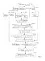
- FIG. 3is a logic flow diagram illustrating a method of reconstructing an image of an object for a multi-slice computed tomography imaging system in accordance with an embodiment of the present invention
- FIG. 4is a representation of a scan including cine mode scans of boundary regions and a helical scan for an intermediate region, with a two-dimensional field of view and corresponding extended boundary regions in accordance with an embodiment of the present invention
- FIG. 5is a perspective view of parallel data access in accordance with an embodiment of the present invention.
- FIG. 6is a two-dimensional field of view and corresponding extended boundary regions in accordance with an embodiment of the present invention.
- image spacerefers to a set of vectors arranged in an array for use with a method of the present invention.
- the arraymay be of any number of dimensions, such as two-dimensional, three-dimensional, four-dimensional, etc.
- An example of an image space that may be used in a method of the present inventionis a set of all possible images representable on a lattice of a given dimension.
- a single element (vector) of the set of the image spacemay be viewed on a visual display apparatus to allow a user to gain information of the interior of a scanned object.
- forward modelrefers to a description of the transformation from the image space of a scanned object to the projection space for a scanned object, as modeled after the operation of the CT imaging system.
- the operation of the forward model on an image vectoris referred to as “forward projection.”
- computed tomography modelrefers to a mathematical description of the relation between a vector in the image space and a vector in the projection space.
- a computed tomography modelincludes a forward model and a cost function chosen to evaluate the closeness of a match between a projection vector and a forward projection of an image vector by a forward model.
- projection spacerefers to a set of vectors of integral X-ray attenuation values.
- the vectors that make up a projection spacemay comprise data from an X-ray CT scanner.
- the vectors that make up a projection spacemay be forward projections of vectors from an image space.
- visual display devicerefers to any type of device such as a CRT monitor, LCD screen, projected image, etc. used to visually inspect multidimensional vectors.
- multi-slice computed tomography imaging systemrefers to an X-ray CT scanner in which a detector array contains multiple rows of detectors, each row displaced from all other rows in the direction of the axis of the system about which the gantry rotates.
- filtered backprojectionrefers to a technique of reconstructing images from projection data by processing data in the projection space, then forming the value of each element in the image space as a linear combination of values from processed data, those values taken from projection space points to which the given image element contributes in forward projection. Filtered backprojection techniques are described in such places as Avinash C. Kak and Malcolm Slaney, “Principles of Computerized Tomographic Imaging,” Classics in Applied Mathematics, 33, SIAM, 2001, ISBN:089871494X, the entire contents and disclosure of which is hereby incorporated by reference.
- high quality reconstruction imagerefers to an image space vector whose accuracy as a representation of the object under study is comparable to those produced by currently available commercial CT imaging systems and known in the art.
- CTcomputed tomography
- Imaging system 10includes a gantry 14 that has a rotating inner portion 16 containing an x-ray source 18 and a detector array 20 .
- X-ray source 18projects a beam of x-rays toward detector array 20 .
- Source 18 and detector array 20rotate about an operably translatable table 22 .
- Table 22is translated along the z-axis between source 18 and detector 20 to perform a helical scan.
- the beamafter passing through medical patient 12 , within a patient bore 24 , is detected at detector array 20 to generate projection data that is used to create a CT image.
- Source 18 and detector array 20rotate about a center axis 30 .
- Beam 32is received by multiple detector elements 34 in multiple detector rows.
- Each detector element 34generates an electrical signal corresponding to the intensity of an impinging x-ray beam.
- beam 32passes through patient 12 , beam 32 is attenuated.
- Rotation of the center portion of the gantry and the operation of source 18are governed by a control mechanism 36 .
- Control mechanism 36includes an x-ray controller 38 that provides power and timing signals to source 18 and a gantry motor controller 40 that controls the rotational speed and position of the center portion of the gantry.
- a data acquisition system (DAS) 42samples analog data from detector elements 34 and converts the analog data to digital signals for subsequent processing.
- An image reconstructor 44receives sampled and digitized x-ray data from DAS 42 and performs high-speed image reconstruction.
- a main controller 46stores the CT image in a mass storage device 48 .
- Main controller 46also receives commands and scanning parameters from an operator via an operator console 50 .
- a display 52allows the operator to observe the reconstructed image and other data from main controller 46 .
- the operator supplied commands and parametersare used by main controller 46 in operation of DAS 42 , x-ray controller 38 , and gantry motor controller 40 .
- main controller 46operates a table motor controller 54 , which translates table 22 to position patient 12 in gantry 14 .
- X-ray controller 38 , gantry motor controller 40 , image reconstructor 44 , main controller 46 , and table motor controller 54are preferably based on micro processors, such as a computer having a central processing unit, memory (RAM and/or ROM), and associated input and output buses.
- X-ray controller 38 , gantry motor controller 40 , image reconstructor 44 , main controller 46 , and table motor controller 54may be a portion of a central control unit or may each be stand-alone components as shown.
- FIG. 3a logic flow diagram illustrating a method of reconstructing an image of patient 12 for a multi-slice CT imaging system in accordance with an embodiment of the present invention is shown.
- step 100system 10 helically scans an object to acquire projection data.
- the detector arraygenerates projection data upon receiving the x-ray beam from the source.
- a helical trajectory 70is shown which is designed to eliminate or reduce boundary effects in accordance with an embodiment of the present invention.
- Helical scan pitchmay be adjusted during the helical scanning. By adjusting helical scan pitch, helical scan pattern is adjusted, decreasing difficulty in handling boundary conditions.
- the scan pitchmay be adjusted at a beginning 72 of a scan series and at an end 74 of a scan series to provide boundary regions 76 of a FOV 78 that either eliminate or reduce the size of extended boundary regions 80 and 81 .
- Setting the pitch equal to zero at boundary regions 76is referred to as cine or step-and-shoot data acquisition mode.
- Regions 80 and 81have zero width when only center detectors 82 of detector array 20 are used. When all detectors 34 are used in cine mode, regions 80 and 81 have a width greater than zero with reduced size relative to the size of regions 80 and 81 in normal full helical mode.
- steps 102 - 104a CT modeled iterative reconstruction technique is performed to reconstruct the image in response to projection data.
- step 102 aimage reconstructor 44 determines a cross-section reconstruction vector, which approximately matches the projection data via a first CT model as shown in equation 1.
- y nF ( ⁇ circumflex over (x) ⁇ , ⁇ n ,z n ) (1)
- system 10is modeled by the function F( ⁇ circumflex over (x) ⁇ , ⁇ n ,z n ) that describes expected output for each detector 34 at each rotation angle ⁇ and z position.
- Vector ⁇ circumflex over (x) ⁇contains a three-dimensional reconstruction of a portion of patient 12 in a plane of reconstruction. Values of vector ⁇ circumflex over (x) ⁇ are determined from known values of y n , ⁇ n , and z n . Rotation angles ⁇ n , and z-axis positions z n correspond to an n th detector measurement or frame. Measured values y n and expected values F( ⁇ circumflex over (x) ⁇ , ⁇ n ,z n ) are compared for each n th frame.
- the present inventiondetermines the contribution of each voxel of an image space to each data point of the projection data.
- a voxelis a volume element, as known in the art, that refers to a value of an object at a particular position in space.
- the vector ⁇ circumflex over (x) ⁇is determined such that equation 1 is satisfied, or in other words, a vector ⁇ circumflex over (x) ⁇ is determined that approximately matches the projection data. Solving equation 1 eliminates traditional interpolation and artifacts that may be caused thereby.
- vector ⁇ circumflex over (x) ⁇may be determined using various methods including iteratively changing vector ⁇ circumflex over (x) ⁇ so that error in equation 1 is reduced.
- algebraic reconstruction techniquesknown in the art, may be used to iteratively change sub-sets of values of vector ⁇ circumflex over (x) ⁇ to reduce error.
- the cross-section reconstruction vector ⁇ circumflex over (x) ⁇may be determined using a first look-up table to determine and account for source-to-detector radiation transfer to voxels at particular locations.
- step 102 d 1another method of determining vector ⁇ circumflex over (x) ⁇ is performed by minimizing differences between expected values F( ⁇ circumflex over (x) ⁇ , ⁇ n ,z n ) and measured values y n by computing a solution to the first CT model within a first cost function of equation 2.
- the first cost functionis summed over the number of frames m and D represents a general non-negative distortion measure.
- distortion measure Dmay be a quadratic error term, as in equation 3.
- D[v]v′Bv (3)
- distortion measure Dis a scalar that is set equal to a transpose of a vector v multiplied by a positive definite matrix B and by a vector v.
- Distortion measure Dmay include non-negative convex functions, negative logarithms of probability density functions, and other penalty functions.
- Equation 2may be expressed with a quadratic form for D as shown in equation 4.
- the first cost functionmay be augmented by a smoothing function to form a second cost function of equation 5.
- Equation 6is a quadratic form of equation 5.
- S(x)is a positive smoothing function, which is selected to be relatively large when the shape of vector ⁇ circumflex over (x) ⁇ is not smooth and relatively small when shape of vector ⁇ circumflex over (x) ⁇ is smooth.
- the cross-section reconstruction vector ⁇ circumflex over (x) ⁇may also be determined using iterative coordinate descent (ICD) to minimize the first cost function or the second cost function.
- ICDiterative coordinate descent
- FIG. 5a perspective view of parallel data access in accordance with an embodiment of the present invention is shown.
- Projection data 84is divided into sets necessary for separate reconstructed slices 86 .
- ICDmay be initiated with a high quality initial reconstruction image.
- the high quality initial reconstructed imagepreferably has accurate representation of the low spatial frequencies in the image, since ICD iterations rapidly correct inaccuracies in the reconstruction at high spatial frequencies.
- Filtered backprojectionis a desirable initial reconstruction because it accurately represents the low frequency content in the reconstruction.
- results of slice nmay be used as an initial condition for slices n ⁇ 1 and n ⁇ 1.
- a low resolution reconstructionmay first be computed, and then it may be interpolated for use as an initial reconstruction at a higher resolution. This process of reconstruction and interpolation may be repeated starting at very coarse resolutions, and completing at a finest desired resolution.
- step 102 e 2speed and memory requirements of ICD may also be improved by appropriately selecting the order in which voxels and slices are updated.
- Slicesmay be accessed in lexicographic order, serpentine order, progressive order, pseudo-random order, or in another applicable order known in the art.
- ICDminimizes a cost function by sequentially updating each voxel. Each voxel is updated to minimize the first cost function or the second cost function while maintaining constant values for other voxels.
- the CT modelis preferably an accurate representation of geometric and physical relationships of components in system 10 .
- the CT modelmay be derived from experimentation, modeling of the source and detector response physics, or computer simulation.
- step 102 e 3for computational efficiency, form of contribution of each of a set of sparsely located voxels to the expected values F( ⁇ circumflex over (x) ⁇ , ⁇ n ,z n ) may be accurately evaluated, with the forms of these contributions then interpolated for immediate voxels.
- Source-to-detector radiation transfer to voxels at particular locationsmay be represented by a second look-up table of values that are indexed by relative positions and orientations of source-detector-voxel.
- the second look-up tableis referred to as a point-spread-function, since it specifies spread of a point voxel influence on nearby detectors.
- FIG. 6a two-dimensional field of view 78 and corresponding extended boundary regions 80 and 81 are shown in accordance with an embodiment of the present invention.
- Helical scan rotationis illustrated by arrow 88 .
- density of material in extended boundary regions 80 and 81affects the measured values y n for frames n near boundaries 76 , but is not accounted for in the function F( ⁇ circumflex over (x) ⁇ , ⁇ n ,z n ) if regions 80 and 81 are not included in x. Therefore, artifacts exist in reconstruction of slices near beginning 72 and end 74 along the z-axis.
- Steps 102 h - 104minimize the boundary artifacts by incorporating extended boundaries 80 and 81 , which are used to estimate effects of boundary regions 76 , represented by extended boundary vectors ⁇ circumflex over (L) ⁇ and ⁇ circumflex over (R) ⁇ .
- Extended boundary vectors ⁇ circumflex over (L) ⁇ and ⁇ circumflex over (R) ⁇account for distortions produced by absorption in the extended boundary regions 80 and 81 .
- step 102 fextended boundary regions 80 and 81 are incorporated within the first CT model to form a second CT model in a third cost function of equation 7 and in quadratic form in equation 8.
- step 102 gthe time required to perform minimization of step 102 f may be decreased and accuracy may be increased by reducing the number of degrees of freedom in vectors ⁇ circumflex over (L) ⁇ and ⁇ circumflex over (R) ⁇ .
- extended boundaries 80 and 81may be represented using lower resolution in regions of less importance.
- the extended boundaries 80 and 81may be sampled more finely near boundary regions 76 and more coarsely at points further from the FOV 78 within regions 80 and 81 .
- the reduction in sampling resolutionmay be achieved by increasing size of voxels along the z-axis, or in directions perpendicular to the z-axis, or in any combination of directions.
- Regions 80 and 81may be represented by a single slice in which each voxel extends to a full extent of regions 80 and 81 .
- the reconstructed objectmay be assumed constant along the z-axis in regions 80 and 81 .
- the extended boundary reconstruction imagesmay be determined using filtered backprojection or other reconstruction technique known in the art in order to provide an approximate estimation of the object in regions 80 and 81 .
- the values of regions R and Lare not changed during the CT modeled iterative reconstruction technique.
- step 102 hthe third cost function is minimized over the regions 80 and 81 with or without incorporation of a smoothing function S(x), its presence depending on whether step 102 d 2 is performed above during the CT modeled iterative reconstruction technique.
- the ICDmay be modified to allow sequential update of voxel subsets.
- the voxel subsetsmay include sub-regions, sparsely sampled sub-regions, or individual two-dimensional slices of a reconstructed volume. Updating of voxel subsets may improve convergence speed and allow for parallel computation.
- Each slice of the reconstructed volumeaccesses a limited range of the helical scan dataset; therefore, slices that are separated by sufficient distance may be processed independently since they do not access or process the same projection measurement data or image plane variables.
- the present inventionprovides a multi-slice CT imaging system and method of reconstructing a CT image using iterative reconstruction while minimizing artifacts.
- the present inventionaccounts directly for geometry of the multi-slice CT imaging system and for extended boundary regions further preventing artifacts and blurring of a reconstructed image.
Landscapes
- Health & Medical Sciences (AREA)
- Engineering & Computer Science (AREA)
- Life Sciences & Earth Sciences (AREA)
- Medical Informatics (AREA)
- Physics & Mathematics (AREA)
- Molecular Biology (AREA)
- Biophysics (AREA)
- Veterinary Medicine (AREA)
- Theoretical Computer Science (AREA)
- Public Health (AREA)
- General Health & Medical Sciences (AREA)
- Animal Behavior & Ethology (AREA)
- Surgery (AREA)
- High Energy & Nuclear Physics (AREA)
- Heart & Thoracic Surgery (AREA)
- Nuclear Medicine, Radiotherapy & Molecular Imaging (AREA)
- Optics & Photonics (AREA)
- Pathology (AREA)
- Radiology & Medical Imaging (AREA)
- Biomedical Technology (AREA)
- General Physics & Mathematics (AREA)
- Mathematical Analysis (AREA)
- Algebra (AREA)
- Mathematical Physics (AREA)
- Pulmonology (AREA)
- Mathematical Optimization (AREA)
- Pure & Applied Mathematics (AREA)
- Apparatus For Radiation Diagnosis (AREA)
Abstract
Description
yn=F({circumflex over (x)},θn,zn) (1)
D[v]=v′Bv (3)
Claims (22)
Priority Applications (1)
| Application Number | Priority Date | Filing Date | Title |
|---|---|---|---|
| US10/319,674US6907102B1 (en) | 2002-12-16 | 2002-12-16 | Iterative reconstruction methods for multi-slice computed tomography |
Applications Claiming Priority (1)
| Application Number | Priority Date | Filing Date | Title |
|---|---|---|---|
| US10/319,674US6907102B1 (en) | 2002-12-16 | 2002-12-16 | Iterative reconstruction methods for multi-slice computed tomography |
Publications (1)
| Publication Number | Publication Date |
|---|---|
| US6907102B1true US6907102B1 (en) | 2005-06-14 |
Family
ID=34632680
Family Applications (1)
| Application Number | Title | Priority Date | Filing Date |
|---|---|---|---|
| US10/319,674Expired - LifetimeUS6907102B1 (en) | 2002-12-16 | 2002-12-16 | Iterative reconstruction methods for multi-slice computed tomography |
Country Status (1)
| Country | Link |
|---|---|
| US (1) | US6907102B1 (en) |
Cited By (35)
| Publication number | Priority date | Publication date | Assignee | Title |
|---|---|---|---|---|
| US20050063611A1 (en)* | 2003-09-24 | 2005-03-24 | Yuusuke Toki | Super-resolution processor and medical diagnostic imaging apparatus |
| US20050259780A1 (en)* | 2004-05-20 | 2005-11-24 | Eastman Kodak Company | Method for reconstructing tomographic images |
| US20060004278A1 (en)* | 2004-02-13 | 2006-01-05 | University Of Chicago | Method, system, and computer software product for feature-based correlation of lesions from multiple images |
| US20060072800A1 (en)* | 2004-09-24 | 2006-04-06 | General Electric Company | Method and system for distributed iterative image reconstruction |
| US20060104408A1 (en)* | 2004-11-17 | 2006-05-18 | General Electric Company | Methods, apparatus, and software to facilitate computing the elements of a forward projection matrix |
| WO2006108926A1 (en)* | 2005-04-13 | 2006-10-19 | General Electric Company | Tomographic method |
| US20070019777A1 (en)* | 2005-07-20 | 2007-01-25 | The University Of Notre Dame Du Lac | Methods, apparatus, and software for reconstructing an image |
| US20070058771A1 (en)* | 2005-09-12 | 2007-03-15 | The University Of Notre Dame | Systems and methods for filtering data in a medical imaging system |
| US20070098133A1 (en)* | 2005-11-02 | 2007-05-03 | Guang-Hong Chen | Method for Increasing the Resolution of a CT Image During Image Reconstruction |
| US20070116343A1 (en)* | 2005-11-22 | 2007-05-24 | Sauer Ken D | Methods and systems for improving quality of an image |
| US20070127801A1 (en)* | 2005-12-01 | 2007-06-07 | Martti Kalke | Method for limited angle tomography |
| US20070147696A1 (en)* | 2005-12-28 | 2007-06-28 | Karl William C | Medical image processing |
| US20070291894A1 (en)* | 2006-06-20 | 2007-12-20 | Akira Hagiwara | X-ray ct data acquisition method and x-ray ct apparatus |
| US20070297660A1 (en)* | 2006-06-22 | 2007-12-27 | General Electric Company | Systems and methods for improving a resolution of an image |
| US20080205737A1 (en)* | 2007-02-23 | 2008-08-28 | Holger Kunze | Method and apparatus for the artifact-reduced detection of a 3D object in tomographic imaging |
| US20080247502A1 (en)* | 2007-04-05 | 2008-10-09 | Liao Hstau Y | System and methods for tomography image reconstruction |
| US20080304726A1 (en)* | 2007-06-05 | 2008-12-11 | Jeffrey Allen Fessler | Methods and systems for improving spatial and temporal resolution of computed images of moving objects |
| US20090190814A1 (en)* | 2008-01-25 | 2009-07-30 | Bouman Charles A | Method and system for image reconstruction |
| US20100054394A1 (en)* | 2008-08-28 | 2010-03-04 | General Electric Company | Method and system for image reconstruction |
| US20100172563A1 (en)* | 2009-01-05 | 2010-07-08 | Akira Hagiwara | X-ray ct apparatus |
| US20110053831A1 (en)* | 2007-06-20 | 2011-03-03 | Phylogica Limited | Compositions and uses thereof for the treatment of acute respiratory distress syndrome (ards) and clinical disorders associated with therewith |
| US20110097007A1 (en)* | 2009-10-28 | 2011-04-28 | General Electric Company | Iterative Reconstruction |
| US20110150305A1 (en)* | 2009-12-17 | 2011-06-23 | General Electric Company | Method and system for correcting artifacts in image reconstruction |
| CN103329168A (en)* | 2011-01-27 | 2013-09-25 | 皇家飞利浦电子股份有限公司 | Truncation Compensation for Iterative Cone Beam CT Reconstruction for SPECT/CT Systems |
| US20150177353A1 (en)* | 2011-04-22 | 2015-06-25 | The General Hospital Corporation | Method for Magnetic Resonance Imaging with Controlled Aliasing |
| US20150281564A1 (en)* | 2014-03-26 | 2015-10-01 | Samsung Electronic Co.,Ltd. | Medical imaging apparatus and method of displaying user interface image |
| US20160120486A1 (en)* | 2014-10-31 | 2016-05-05 | Kabushiki Kaisha Toshiba | X-ray ct apparatus |
| US20180182129A1 (en)* | 2015-09-09 | 2018-06-28 | Tsinghua University | Spectral ct image reconstructing method and spectral ct imaging system |
| WO2018156803A1 (en) | 2017-02-24 | 2018-08-30 | Bayer Healthcare Llc | Systems and methods for generating simulated computed tomography (ct) images |
| US20180268185A1 (en)* | 2013-03-15 | 2018-09-20 | The Regents of the University of Colorado, a body corporate. | 3-D Localization And Imaging of Dense Arrays of Particles |
| US10559100B2 (en) | 2017-05-22 | 2020-02-11 | Prismatic Sensors Ab | Method and devices for image reconstruction |
| CN111553958A (en)* | 2019-02-08 | 2020-08-18 | 西门子医疗有限公司 | Calculation of image matrix size |
| CN112330766A (en)* | 2019-11-04 | 2021-02-05 | 上海联影医疗科技股份有限公司 | System and method for tomography |
| CN114983452A (en)* | 2022-05-11 | 2022-09-02 | 赛诺威盛科技(北京)股份有限公司 | CT spiral reconstruction image artifact removing method and device |
| WO2022198729A1 (en)* | 2021-03-25 | 2022-09-29 | 上海涛影医疗科技有限公司 | X-ray tomography system |
Citations (1)
| Publication number | Priority date | Publication date | Assignee | Title |
|---|---|---|---|---|
| US6768782B1 (en)* | 2002-12-16 | 2004-07-27 | University Of Notre Dame Du Lac | Iterative method for region-of-interest reconstruction |
- 2002
- 2002-12-16USUS10/319,674patent/US6907102B1/ennot_activeExpired - Lifetime
Patent Citations (1)
| Publication number | Priority date | Publication date | Assignee | Title |
|---|---|---|---|---|
| US6768782B1 (en)* | 2002-12-16 | 2004-07-27 | University Of Notre Dame Du Lac | Iterative method for region-of-interest reconstruction |
Non-Patent Citations (7)
| Title |
|---|
| Allain et al., "Approche regularisee en reconstruction tomographique 3D helicoidale," Proceedings of the 2001 GRETSI Symposium on Signal and Image Processing, 2001, Toulouse, France (An english abstract is present on front page of reference). |
| Bouman et al., "A Unified Approach to Statistical Tomography Using Coordinate Descent Optimization" IEEE Transactions on Image Processing vol. 5, No. 3, Mar. 1996. |
| Herbert et al., "A Generalized EM Algorithm for 3-D Bayesian Reconstruction From Poisson Data Using Gibbs Priors" IEEE Transactions on Medical Imaging vol. 8, No. 2, Jun. 1989. |
| Kak et al., "Algebraic Reconstruction Algorithms" Principles of Computerized Tomographic Imaging (IEEE Press, 1988), pp. 275-296 Note: Principles of Computerized Tomographic Imaging is now published by the Society for Industrial and Applied Mathmatics. |
| Kak et al., "Algorithms for Reconstruction with Nondiffracting Sources" Principles of Computerized Tomographic Imaging (IEEE Press, 1988), pp. 49-112 Note: Principles of Computerized Tomographic Imaging is now published by the Society for Industrial and Applied Mathematics. |
| Sauer et al., "A Local Update Strategy for Iterative Reconstruction from Projections" IEEE Transactions on Signal Processing vol. 41, No. 2, Feb. 1993. |
| Shepp et al., "Maximum Likelihood Reconstruction for Emission Tomography" IEEE Transactions on Medical Imaging vol. MI-1, No. 2, Oct. 1982. |
Cited By (69)
| Publication number | Priority date | Publication date | Assignee | Title |
|---|---|---|---|---|
| US7492967B2 (en)* | 2003-09-24 | 2009-02-17 | Kabushiki Kaisha Toshiba | Super-resolution processor and medical diagnostic imaging apparatus |
| US20050063611A1 (en)* | 2003-09-24 | 2005-03-24 | Yuusuke Toki | Super-resolution processor and medical diagnostic imaging apparatus |
| US20060004278A1 (en)* | 2004-02-13 | 2006-01-05 | University Of Chicago | Method, system, and computer software product for feature-based correlation of lesions from multiple images |
| US7298881B2 (en)* | 2004-02-13 | 2007-11-20 | University Of Chicago | Method, system, and computer software product for feature-based correlation of lesions from multiple images |
| US20050259780A1 (en)* | 2004-05-20 | 2005-11-24 | Eastman Kodak Company | Method for reconstructing tomographic images |
| US7042974B2 (en)* | 2004-05-20 | 2006-05-09 | Eastman Kodak Company | Method for reconstructing tomographic images |
| US20060072800A1 (en)* | 2004-09-24 | 2006-04-06 | General Electric Company | Method and system for distributed iterative image reconstruction |
| US7272205B2 (en)* | 2004-11-17 | 2007-09-18 | Purdue Research Foundation | Methods, apparatus, and software to facilitate computing the elements of a forward projection matrix |
| US20060104408A1 (en)* | 2004-11-17 | 2006-05-18 | General Electric Company | Methods, apparatus, and software to facilitate computing the elements of a forward projection matrix |
| US20080187090A1 (en)* | 2005-04-13 | 2008-08-07 | Martti Kalke | Tomographic Method |
| WO2006108926A1 (en)* | 2005-04-13 | 2006-10-19 | General Electric Company | Tomographic method |
| US20070019777A1 (en)* | 2005-07-20 | 2007-01-25 | The University Of Notre Dame Du Lac | Methods, apparatus, and software for reconstructing an image |
| US7327822B2 (en) | 2005-07-20 | 2008-02-05 | Purdue Research Foundation | Methods, apparatus, and software for reconstructing an image |
| US7676074B2 (en) | 2005-09-12 | 2010-03-09 | Purdue Research Foundation | Systems and methods for filtering data in a medical imaging system |
| US20070058771A1 (en)* | 2005-09-12 | 2007-03-15 | The University Of Notre Dame | Systems and methods for filtering data in a medical imaging system |
| US7602879B2 (en)* | 2005-11-02 | 2009-10-13 | Wisconsin Alumni Research Foundation | Method for increasing the resolution of a CT image during image reconstruction |
| US20070098133A1 (en)* | 2005-11-02 | 2007-05-03 | Guang-Hong Chen | Method for Increasing the Resolution of a CT Image During Image Reconstruction |
| US20070116343A1 (en)* | 2005-11-22 | 2007-05-24 | Sauer Ken D | Methods and systems for improving quality of an image |
| US7983462B2 (en)* | 2005-11-22 | 2011-07-19 | Purdue Research Foundation | Methods and systems for improving quality of an image |
| US7853056B2 (en)* | 2005-12-01 | 2010-12-14 | Martti Kalke | Method for limited angle tomography |
| US20070127801A1 (en)* | 2005-12-01 | 2007-06-07 | Martti Kalke | Method for limited angle tomography |
| US7689017B2 (en)* | 2005-12-28 | 2010-03-30 | The General Hospital Corporation | Medical image processing |
| US20070147696A1 (en)* | 2005-12-28 | 2007-06-28 | Karl William C | Medical image processing |
| US20070291894A1 (en)* | 2006-06-20 | 2007-12-20 | Akira Hagiwara | X-ray ct data acquisition method and x-ray ct apparatus |
| NL1034005C2 (en)* | 2006-06-20 | 2008-12-30 | Ge Med Sys Global Tech Co Llc | X-ray CT data acquisition method and X-ray CT equipment. |
| US7649972B2 (en)* | 2006-06-20 | 2010-01-19 | Ge Medical Systems Global Technology Company, Llc | X-ray CT data acquisition method and X-ray CT apparatus |
| US20070297660A1 (en)* | 2006-06-22 | 2007-12-27 | General Electric Company | Systems and methods for improving a resolution of an image |
| US7583780B2 (en) | 2006-06-22 | 2009-09-01 | General Electric Company | Systems and methods for improving a resolution of an image |
| US8175361B2 (en)* | 2007-02-23 | 2012-05-08 | Siemens Aktiengesellschaft | Method and apparatus for the artifact-reduced detection of a 3D object in tomographic imaging |
| US20080205737A1 (en)* | 2007-02-23 | 2008-08-28 | Holger Kunze | Method and apparatus for the artifact-reduced detection of a 3D object in tomographic imaging |
| US20080247502A1 (en)* | 2007-04-05 | 2008-10-09 | Liao Hstau Y | System and methods for tomography image reconstruction |
| US7840053B2 (en) | 2007-04-05 | 2010-11-23 | Liao Hstau Y | System and methods for tomography image reconstruction |
| US8233682B2 (en)* | 2007-06-05 | 2012-07-31 | General Electric Company | Methods and systems for improving spatial and temporal resolution of computed images of moving objects |
| US20080304726A1 (en)* | 2007-06-05 | 2008-12-11 | Jeffrey Allen Fessler | Methods and systems for improving spatial and temporal resolution of computed images of moving objects |
| US20110053831A1 (en)* | 2007-06-20 | 2011-03-03 | Phylogica Limited | Compositions and uses thereof for the treatment of acute respiratory distress syndrome (ards) and clinical disorders associated with therewith |
| US8135186B2 (en)* | 2008-01-25 | 2012-03-13 | Purdue Research Foundation | Method and system for image reconstruction |
| US20090190814A1 (en)* | 2008-01-25 | 2009-07-30 | Bouman Charles A | Method and system for image reconstruction |
| US20100054394A1 (en)* | 2008-08-28 | 2010-03-04 | General Electric Company | Method and system for image reconstruction |
| US7885371B2 (en) | 2008-08-28 | 2011-02-08 | General Electric Company | Method and system for image reconstruction |
| US20100172563A1 (en)* | 2009-01-05 | 2010-07-08 | Akira Hagiwara | X-ray ct apparatus |
| US8358824B2 (en) | 2009-01-05 | 2013-01-22 | Ge Medical Systems Global Technology Company, Llc | X-ray CT apparatus |
| US8655033B2 (en)* | 2009-10-28 | 2014-02-18 | General Electric Company | Iterative reconstruction |
| US20110097007A1 (en)* | 2009-10-28 | 2011-04-28 | General Electric Company | Iterative Reconstruction |
| US20110150305A1 (en)* | 2009-12-17 | 2011-06-23 | General Electric Company | Method and system for correcting artifacts in image reconstruction |
| US8731266B2 (en) | 2009-12-17 | 2014-05-20 | General Electric Company | Method and system for correcting artifacts in image reconstruction |
| US9462988B2 (en)* | 2011-01-27 | 2016-10-11 | Koninklijke Philips N.V. | Truncation compensation for iterative cone-beam CT reconstruction for SPECT/CT systems |
| RU2606561C2 (en)* | 2011-01-27 | 2017-01-10 | Конинклейке Филипс Электроникс Н.В. | Truncation compensation for iterative reconstruction in computed tomography (ct) with conical beam in combined spect/ct systems |
| US20130294570A1 (en)* | 2011-01-27 | 2013-11-07 | Koninklijke Philips Electronics N.V. | Truncation compensation for iterative cone-beam ct reconstruction for spect/ct systems |
| JP2014507988A (en)* | 2011-01-27 | 2014-04-03 | コーニンクレッカ フィリップス エヌ ヴェ | Truncation correction for iterative cone beam CT reconstruction for SPECT / CT systems |
| CN103329168A (en)* | 2011-01-27 | 2013-09-25 | 皇家飞利浦电子股份有限公司 | Truncation Compensation for Iterative Cone Beam CT Reconstruction for SPECT/CT Systems |
| US20150177353A1 (en)* | 2011-04-22 | 2015-06-25 | The General Hospital Corporation | Method for Magnetic Resonance Imaging with Controlled Aliasing |
| US10139465B2 (en)* | 2011-04-22 | 2018-11-27 | The General Hospital Corporation | Method for magnetic resonance imaging with controlled aliasing |
| US20180268185A1 (en)* | 2013-03-15 | 2018-09-20 | The Regents of the University of Colorado, a body corporate. | 3-D Localization And Imaging of Dense Arrays of Particles |
| US10657346B2 (en)* | 2013-03-15 | 2020-05-19 | The Regents Of The University Of Colorado, A Body Corporate | 3-D localization and imaging of dense arrays of particles |
| US20150281564A1 (en)* | 2014-03-26 | 2015-10-01 | Samsung Electronic Co.,Ltd. | Medical imaging apparatus and method of displaying user interface image |
| US10061488B2 (en)* | 2014-03-26 | 2018-08-28 | Samsung Electronics Co., Ltd. | Medical imaging apparatus and method of displaying user interface image |
| US10111626B2 (en)* | 2014-10-31 | 2018-10-30 | Toshiba Medical Systems Corporation | X-ray CT apparatus |
| US20160120486A1 (en)* | 2014-10-31 | 2016-05-05 | Kabushiki Kaisha Toshiba | X-ray ct apparatus |
| US20180182129A1 (en)* | 2015-09-09 | 2018-06-28 | Tsinghua University | Spectral ct image reconstructing method and spectral ct imaging system |
| US10489939B2 (en)* | 2015-09-09 | 2019-11-26 | Tsinghua University | Spectral CT image reconstructing method and spectral CT imaging system |
| WO2018156803A1 (en) | 2017-02-24 | 2018-08-30 | Bayer Healthcare Llc | Systems and methods for generating simulated computed tomography (ct) images |
| US11000255B2 (en) | 2017-02-24 | 2021-05-11 | Bayer Healthcare Llc | Systems and methods for generating simulated computed tomography (CT) images |
| US10559100B2 (en) | 2017-05-22 | 2020-02-11 | Prismatic Sensors Ab | Method and devices for image reconstruction |
| CN111553958A (en)* | 2019-02-08 | 2020-08-18 | 西门子医疗有限公司 | Calculation of image matrix size |
| CN111553958B (en)* | 2019-02-08 | 2023-11-03 | 西门子医疗有限公司 | Calculation of image matrix size |
| CN112330766A (en)* | 2019-11-04 | 2021-02-05 | 上海联影医疗科技股份有限公司 | System and method for tomography |
| CN112330766B (en)* | 2019-11-04 | 2023-05-02 | 上海联影医疗科技股份有限公司 | A system and method for tomographic imaging |
| WO2022198729A1 (en)* | 2021-03-25 | 2022-09-29 | 上海涛影医疗科技有限公司 | X-ray tomography system |
| CN114983452A (en)* | 2022-05-11 | 2022-09-02 | 赛诺威盛科技(北京)股份有限公司 | CT spiral reconstruction image artifact removing method and device |
Similar Documents
| Publication | Publication Date | Title |
|---|---|---|
| US6907102B1 (en) | Iterative reconstruction methods for multi-slice computed tomography | |
| US7885371B2 (en) | Method and system for image reconstruction | |
| US8135186B2 (en) | Method and system for image reconstruction | |
| US6768782B1 (en) | Iterative method for region-of-interest reconstruction | |
| US9189871B2 (en) | Image reconstruction from limited or incomplete data | |
| US8885975B2 (en) | Method and apparatus for iterative reconstruction | |
| US9245320B2 (en) | Method and system for correcting artifacts in image reconstruction | |
| US6507633B1 (en) | Method for statistically reconstructing a polyenergetic X-ray computed tomography image and image reconstructor apparatus utilizing the method | |
| US8229199B2 (en) | Method for image reconstruction using sparsity-constrained correction | |
| US7280630B2 (en) | Calculation of additional projection data from projection data acquired with a divergent beam | |
| EP1478274A2 (en) | Methods and apparatus for divergent fast beam tomography | |
| US10049446B2 (en) | Accelerated statistical iterative reconstruction | |
| EP1800264B1 (en) | Image reconstruction with voxel dependent interpolation | |
| EP2067122B1 (en) | Ray consistency based reconstruction of helical cone beam data | |
| US7272205B2 (en) | Methods, apparatus, and software to facilitate computing the elements of a forward projection matrix | |
| US9508164B2 (en) | Fast iterative image reconstruction method for 3D computed tomography | |
| US7308071B2 (en) | Methods, apparatus, and software for reconstructing an image | |
| Bertram et al. | Monte-Carlo scatter correction for cone-beam computed tomography with limited scan field-of-view | |
| US10307114B1 (en) | Iterative volume image reconstruction using synthetic projection images | |
| Grangeat et al. | Indirect cone-beam three-dimensional image reconstruction | |
| US10573029B2 (en) | Fast iterative image reconstruction method for emission tomography | |
| US7646842B2 (en) | Methods and apparatus for reconstructing thick image slices | |
| US20250232491A1 (en) | Statistical reconstruction method based on a continuous-to-continuous data model with iterative coordinate descent optimization strategy for emission tomography | |
| Al-anbari et al. | Evaluation performance of iterative algorithms for 3D image reconstruction in cone beam geometry | |
| Lin et al. | A multiple cone-beam reconstruction algorithm for X-ray microtomography |
Legal Events
| Date | Code | Title | Description |
|---|---|---|---|
| STCF | Information on status: patent grant | Free format text:PATENTED CASE | |
| FEPP | Fee payment procedure | Free format text:PAYER NUMBER DE-ASSIGNED (ORIGINAL EVENT CODE: RMPN); ENTITY STATUS OF PATENT OWNER: LARGE ENTITY Free format text:PAYOR NUMBER ASSIGNED (ORIGINAL EVENT CODE: ASPN); ENTITY STATUS OF PATENT OWNER: LARGE ENTITY | |
| FPAY | Fee payment | Year of fee payment:4 | |
| FPAY | Fee payment | Year of fee payment:8 | |
| AS | Assignment | Owner name:PURDUE RESEARCH FOUNDATION, INDIANA Free format text:ASSIGNMENT OF ASSIGNORS INTEREST;ASSIGNOR:BOUMAN, CHARLES ADDISON;REEL/FRAME:032922/0863 Effective date:20041115 | |
| AS | Assignment | Owner name:UNIVERSITY OF NOTRE DAME DU LAC, INDIANA Free format text:ASSIGNMENT OF ASSIGNORS INTEREST;ASSIGNOR:SAUER, KEN D;REEL/FRAME:032934/0333 Effective date:20041110 Owner name:GENERAL ELECTRIC COMPANY, NEW YORK Free format text:ASSIGNMENT OF ASSIGNORS INTEREST;ASSIGNORS:THIBAULT, JEAN-BAPTISTE;HSIEH, JIANG;REEL/FRAME:032934/0580 Effective date:20140509 | |
| FPAY | Fee payment | Year of fee payment:12 |