US6907015B1 - Radio communication system - Google Patents
Radio communication systemDownload PDFInfo
- Publication number
- US6907015B1 US6907015B1US09/631,353US63135300AUS6907015B1US 6907015 B1US6907015 B1US 6907015B1US 63135300 AUS63135300 AUS 63135300AUS 6907015 B1US6907015 B1US 6907015B1
- Authority
- US
- United States
- Prior art keywords
- channel
- transmitting
- station
- primary station
- random access
- Prior art date
- Legal status (The legal status is an assumption and is not a legal conclusion. Google has not performed a legal analysis and makes no representation as to the accuracy of the status listed.)
- Expired - Lifetime, expires
Links
- 238000004891communicationMethods0.000titleclaimsabstractdescription18
- 230000005540biological transmissionEffects0.000claimsabstractdescription32
- 230000004044responseEffects0.000claimsdescription32
- 238000000034methodMethods0.000claimsdescription21
- 230000011664signalingEffects0.000claimsdescription5
- 230000008054signal transmissionEffects0.000claimsdescription2
- 238000013507mappingMethods0.000description13
- 230000008569processEffects0.000description4
- 238000012986modificationMethods0.000description3
- 230000004048modificationEffects0.000description3
- 230000008901benefitEffects0.000description2
- 230000001934delayEffects0.000description1
- 238000013461designMethods0.000description1
- 238000010586diagramMethods0.000description1
- 230000000694effectsEffects0.000description1
- 230000006872improvementEffects0.000description1
- 238000004519manufacturing processMethods0.000description1
Images


Classifications
- H—ELECTRICITY
- H04—ELECTRIC COMMUNICATION TECHNIQUE
- H04W—WIRELESS COMMUNICATION NETWORKS
- H04W74/00—Wireless channel access
- H04W74/08—Non-scheduled access, e.g. ALOHA
- H04W74/0833—Random access procedures, e.g. with 4-step access
- H—ELECTRICITY
- H04—ELECTRIC COMMUNICATION TECHNIQUE
- H04W—WIRELESS COMMUNICATION NETWORKS
- H04W74/00—Wireless channel access
- H04W74/08—Non-scheduled access, e.g. ALOHA
- H04W74/0833—Random access procedures, e.g. with 4-step access
- H04W74/0841—Random access procedures, e.g. with 4-step access with collision treatment
- H—ELECTRICITY
- H04—ELECTRIC COMMUNICATION TECHNIQUE
- H04W—WIRELESS COMMUNICATION NETWORKS
- H04W72/00—Local resource management
- H04W72/04—Wireless resource allocation
- H—ELECTRICITY
- H04—ELECTRIC COMMUNICATION TECHNIQUE
- H04W—WIRELESS COMMUNICATION NETWORKS
- H04W72/00—Local resource management
- H04W72/50—Allocation or scheduling criteria for wireless resources
- H04W72/54—Allocation or scheduling criteria for wireless resources based on quality criteria
- H—ELECTRICITY
- H04—ELECTRIC COMMUNICATION TECHNIQUE
- H04W—WIRELESS COMMUNICATION NETWORKS
- H04W74/00—Wireless channel access
- H04W74/002—Transmission of channel access control information
- H—ELECTRICITY
- H04—ELECTRIC COMMUNICATION TECHNIQUE
- H04W—WIRELESS COMMUNICATION NETWORKS
- H04W28/00—Network traffic management; Network resource management
- H04W28/02—Traffic management, e.g. flow control or congestion control
- H04W28/10—Flow control between communication endpoints
- H04W28/12—Flow control between communication endpoints using signalling between network elements
- H—ELECTRICITY
- H04—ELECTRIC COMMUNICATION TECHNIQUE
- H04W—WIRELESS COMMUNICATION NETWORKS
- H04W4/00—Services specially adapted for wireless communication networks; Facilities therefor
- H04W4/20—Services signaling; Auxiliary data signalling, i.e. transmitting data via a non-traffic channel
- H—ELECTRICITY
- H04—ELECTRIC COMMUNICATION TECHNIQUE
- H04W—WIRELESS COMMUNICATION NETWORKS
- H04W72/00—Local resource management
- H04W72/20—Control channels or signalling for resource management
- H04W72/23—Control channels or signalling for resource management in the downlink direction of a wireless link, i.e. towards a terminal
- H—ELECTRICITY
- H04—ELECTRIC COMMUNICATION TECHNIQUE
- H04W—WIRELESS COMMUNICATION NETWORKS
- H04W74/00—Wireless channel access
- H04W74/002—Transmission of channel access control information
- H04W74/004—Transmission of channel access control information in the uplink, i.e. towards network
Definitions
- the present inventionrelates to a radio communication system having a random access channel for the transmission of data from a secondary station to a primary station, and further relates to primary and secondary stations for use in such a system and to a method of operating such a system. While the present specification describes a system with particular reference to the emerging Universal Mobile Telecommunication System (UMTS), it is to be understood that the techniques described are equally applicable to use in other mobile radio systems.
- UMTSUniversal Mobile Telecommunication System
- random access channelrefers to the logical channel on which random access transmissions take place, which would typically consist of a number of distinct physical channels.
- a random access channelis a normal component of a radio communication system, enabling a Mobile Station (MS) to send short messages to a Base Station (BS).
- Applicationsinclude signalling to the BS when the MS is turned on, sending a packet of data to the BS when the MS may not be engaged in a call, and requesting the BS to allocate a resource for the MS to use.
- a number of random access packet channels available to a MSthere are a number of random access packet channels available to a MS.
- a request for access to a packet channel sent by the MSis encoded with a randomly-chosen signature, which corresponds to one of the packet channels. If the channel is available for use, the BS allocates it to the requesting MS.
- An object of the present inventionis to provide improved allocation of a random access channel to a MS.
- a radio access channel to a MSAccording to a first aspect of the present invention there is provided a radio access channel to a MS.
- a radio communication systemhaving a random access channel for the transmission of data from a secondary station to a primary station, the secondary station having means for requesting access to a random access channel resource by transmitting a signal encoded with a first signature corresponding to the resource, the primary station having means for transmitting a response to the request, the secondary station having means for subsequently transmitting a contention resolution signal encoded with a second signature, and the primary station having means for transmitting a further response to the contention resolution signal, for selecting a random access channel to which the secondary station will be granted access, and for transmitting a channel allocation signal identifying this channel at the same time as at least one of the responses.
- a primary stationfor use in a radio communication system having a random access channel for the transmission of data from a secondary station to the primary station, wherein means are provided for transmitting a response to a request from the secondary station for access to a random access channel resource, the request comprising transmission of a signal encoded with a first signature, for transmitting a further response to a subsequent contention resolution signal encoded with a second signature transmitted by the secondary station, for selecting a random access channel to which the secondary station will be granted access, and for transmitting a channel allocation signal identifying this channel at the same time as at least one of the responses.
- a secondary stationfor use in a radio communication system having a random access channel for the transmission of data to a primary station, wherein means are provided for requesting access to a random access channel resource by transmitting a signal encoded with a first signature corresponding to the resource, for receiving a response from the primary station and subsequently transmitting a contention resolution signal encoded with a second signature, for receiving a further response from the primary station, and for determining which channel has been allocated from a channel allocation signal transmitted by the primary station at the same time as at least one of the responses.
- a method of operating a radio communication system having a random access channel for the transmission of data from a secondary station to a primary stationcomprising the secondary station requesting access to a random access channel resource by transmitting a signal encoded with a first signature corresponding to the resource, the primary station transmitting a response to the request, the secondary station subsequently transmitting a contention resolution signal encoded with a second signature, and the primary station transmitting a further response to the contention resolution signal, selecting a random access channel to which the secondary station will be granted access, and transmitting a channel allocation signal identifying this channel at the same time as at least one of the responses.
- FIG. 1is a block schematic diagram of a radio communication system
- FIG. 2illustrates a basic random access packet channel scheme
- FIG. 3is a table showing one possible set of 16 preamble signatures
- FIG. 4illustrates an enhanced random access packet channel scheme having a packet channel availability message
- FIG. 5is a flow chart illustrating a method in accordance with the present invention for improved allocation of a random access packet channel.
- a radio communication systemcomprises a primary station (BS) 100 and a plurality of secondary stations (MS) 110 .
- the BS 100comprises a microcontroller ( ⁇ C) 102 , transceiver means (Tx/Rx) 104 connected to antenna means 106 , power control means (PC) 107 for altering the transmitted power level, and connection means 108 for connection to the PSTN or other suitable network.
- Each MS 110comprises a microcontroller ( ⁇ C) 112 , transceiver means (Tx/Rx) 114 connected to antenna means 116 , and power control means (PC) 118 for altering the transmitted power level.
- Communication from BS 100 to MS 110takes place on a downlink channel 122
- communication from MS 110 to BS 100takes place on an uplink channel 124 .
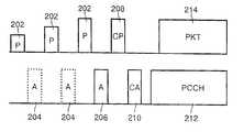
- FIG. 2A basic scheme for a random access packet channel operating in a frequency division duplex system is shown in FIG. 2 , with the uplink channel 124 drawn above the downlink channel 122 .
- the MS 110first transmits a preamble (P) 202 , encoded with a signature randomly chosen from a set of 16 possible signatures, at a low power level in a particular access slot.
- Ppreamble
- a signatureis a signal characterised by its scrambling code and channelisation code modulated by a specific bit sequence.
- a mutually orthogonal set of signaturescan be obtained by defining a set of mutually orthogonal bit sequences for the modulation.
- One example of such a setis shown in FIG. 3 , the set comprising 16 signatures P 0 to P 15 .
- the inverse of each signatureis obtained by interchanging A and ⁇ A.
- the signatures and their inversesare all mutually orthogonal.
- a different set of signaturescan be obtained by changing the scrambling code or the channelisation code (i.e. the physical channel), or by using a different mutually orthogonal set of bit sequences.
- a larger set of signaturesmay be defined in such a way as to have low cross correlations, rather than strict orthogonally.
- the present specificationrefers to sets of 16 signatures different implementations may use sets having different numbers of signatures.
- the choice of preamble signature for encoding the access preamble 202determines the physical channel requested by the MS 110 , with each preamble signature corresponding to a limited number of uplink and downlink channels. If the BS 100 receives and decodes the preamble correctly it transmits a preamble acknowledgement (A) 206 .
- Apreamble acknowledgement
- the BS 100receives and decodes the preamble correctly it transmits a preamble acknowledgement (A) 206 .
- Apreamble acknowledgement
- FIG. 2after the first preamble 202 is transmitted no acknowledgement is returned in the slot 204 allocated for it (which might typically be 1 ms in length).
- the MS 110therefore transmits another preamble 202 at a higher power level. Again no acknowledgement is received in the slot 204 , so the MS 110 transmits another preamble 202 at a still higher power. This is received and decoded by the BS 100 , which transmits an acknowledgement 206 and thereby completes
- the acknowledgement 206may be positive, to signal that the requested channels are free, or negative, to signal that they are in use and access is denied to the MS 110 .
- a negative acknowledgement (NACK)may be indicated by the BS 100 inverting the phase of the signature (with respect to some reference or pilot signal). Alternatively, some of the signatures used by the BS 100 for acknowledgement may also be used as a NACK.
- the BS 100will only transmit one acknowledgement for each access slot, however many preambles 202 were transmitted. One basis for the selection could be to acknowledge the preamble 202 received with the highest power. If more than one preamble 202 was transmitted but each preamble was encoded with a different signature then each MS 110 will know whether or not its preamble 202 was received correctly. However, it is possible that more than one MS 110 selected the same signature, and therefore believes that its preamble 202 has been received. If each of these mobile stations 110 begins to transmit its data the result will be a collision, with none of the data likely to be received correctly.
- a contention resolution phasefollows the transmission of an acknowledgement 206 which indicated that the requested channels were free.
- Each MS 110 which transmitted a preamble 202 encoded with a signature corresponding to that acknowledged by the BS 100now transmits a further contention resolution preamble (CP) 208 .
- This preamble 208is encoded with a signature randomly selected from another set of 16 possible signatures. This set may be different from the set used for the access preamble 202 (either by changing the set of modulating bit sequences, the scrambling code or the channelisation code), or alternatively the set of signatures may be shared between access and contention resolution phases.
- the BS 100then issues a contention resolution acknowledgement (CA) 210 corresponding to the selected preamble 208 , for example that received with the highest power, which acknowledgement 210 enables the MS 110 to transmit its data.
- CAcontention resolution acknowledgement
- the BS 100After this contention resolution phase the BS 100 begins transmission of a Physical Control CHannel (PCCH) 212 , which includes power control information to instruct the MS 110 to adjust its transmission power as necessary, and the MS 110 transmits one or more data packets (PKT) 214 on the allocated packet channel, which is normally on a different physical channel to those used for the preamble transmissions.
- PCCHPhysical Control CHannel
- PKTdata packets
- the PCCH 212may begin simultaneously with the transmission of the data 214 , or may precede it sufficiently for closed loop power control to be established before the data transmission.
- a particular problem with the basis scheme described aboveis that a MS 110 may be denied access to a packet channel corresponding to its selected preamble signature, even though other suitable channels may be available. This makes it likely that a MS 110 will spend significant time waiting for a channel to become available, particularly when traffic loading is high.
- this problemis alleviated by enabling the BS 100 to signal allocation of a packet channel at the same time as it transmits an access acknowledgement 206 or a contention resolution acknowledgement 210 .
- This signallingmay form part of the acknowledgement 206 , 210 or may be transmitted at the same time, preferably with the same channelisation code.
- the BS 100also transmits a packet channel availability (AV) message 402 to enable a MS 110 to determine whether its required channel is available before requesting access.
- AVpacket channel availability
- FIG. 5is a flow chart summarising a method in accordance with the present invention for improved allocation of a random access packet channel to a MS 110 .
- the methodstarts, at step 502 , with a MS 110 having data for transmission on the random access packet channel.
- the MS 110receives, at step 504 , the AV message 402 which gives information on available channels and bit rates.
- One possible format for this messageis a three-bit word, sent once in every 10 ms frame, indicating the highest available bit rate (in kbps) from the set (0, 60, 120, 240, 480, 960, 1920).
- a particularly convenient location for this message in a UMTS embodimentis in an otherwise unused part of a channel, for example a paging indicator channel (PICH) which has 12 unused bits per frame (or in another physical channel having the same channelisation code as the PICH but only occupying the space left by the unused bits in the PICH).
- PICHpaging indicator channel
- the MS 110determines, at step 506 , whether the required bit rate is available. If the available bit rate is zero, or the MS 110 determines that the available bit rate is not sufficient, then the process restarts at step 504 . If the available bit rate is sufficient, the MS 110 can proceed. Before proceeding the MS 110 may wait for a short random back-off period, preferably of up to one frame, to reduce the probability of excessive collisions if a number of MS's 110 simultaneously determine that the same resource is free.
- the MS 110selects a bit rate (which is equal to or less than the maximum currently available) and sets its transmission power to a minimum power level. This power level is typically determined by the MS 110 using open loop power control, so that a MS 110 is not at a disadvantage compared to another MS 110 nearer to the BS 100 .
- the MS 110transmits, at step 508 , an access preamble 202 encoded using a signature corresponding to the selected bit rate.
- Each of the available signaturesis mapped to a single bit rate for the packet channel, and a corresponding PCCH 212 .
- the set of available signatures, and mappings between signatures and bit rates,could for example be regularly broadcast by the BS 100 . If there is more than one signature available corresponding to its required bit rate the MS 110 selects one at random.
- the MS 110now determines, at step 510 , whether it has received an acknowledgement 206 from the BS 100 . If no acknowledgement is received the MS 110 increases its transmission power, at step 512 , and returns to step 508 . If an acknowledgement is received the MS 110 determines, at step 514 , whether the acknowledgement was positive, in which case the process continues, or negative, in which case the MS 110 waits for a random back-off period and returns to step 504 .
- the MS 110transmits a contention resolution preamble 208 using a randomly selected signature.
- the BS 100acknowledges at most one of the contention resolution preambles 208 , and at the same time indicates the channelisation code for the PCCH 212 and the scrambling code for the uplink packet channel.
- the signaturesmay be divided into two sets. The first set and its inverses are used for acknowledgements 210 , while the second set and its inverses are used for channel assignments.
- the MS 110determines, at step 518 , whether it received a contention resolution acknowledgement 210 from the BS 110 . If a CA 210 was received the MS 110 is able to proceed to transmit, at step 520 , its data packets 214 on the assigned channel, after which the method ends at step 522 . If no CA 210 was received, the MS 110 waits for a random back-off period and returns to step 504 . In this case it is preferable for the MS 110 to keep its transmission power set to the same level as that for the original preamble 202 that appeared to be acknowledged by the BS 100 .
- the method in accordance with the present invention described abovehas a number of advantages.
- the flexibility of the systemis improved, since any combination of uplink bit rates can be used (within the capability of the BS 100 or the limit of resources allocated to the packet channel).
- To achieve this flexibility in known systemsrequires frequent updating of broadcast parameters.
- Sending the CA 210 at the same time as the channel allocationminimises delay, while increasing the probability that the MS 110 can obtain access to a packet channel even if many of the available channels are in use.
- a multi-stage processcan be used, involving the transmission of two or more contention resolution preambles 208 and corresponding acknowledgements 210 .
- the signatures used for successive preambles 208can be chosen from the same set or from further sets.
- Such a processis described in our co-pending UK patent application 9914926.2 (our reference PHB 34352).
- the channel allocation informationcould also be split between the contention resolution phases (and possibly also shared with the access acknowledgement 206 ).
- the channel allocation informationcould be repeated in each acknowledgement 206 , 210 .
- the packet channel availability message 402uses only 3 bits per frame, which is a very low overhead considering the saving in downlink signalling at times of high loading.
- An update rate of the order of once per frameis a reasonable compromise between downlink overhead and delay, since the overall transmission delay will be dominated by the time taken to transmit the data packets 214 , typically a few frames.
- a MS 110could monitor system activity to determine what packet channels are likely to be free. However, this requires the MS 110 to monitor for an extended period before transmitting, and the information obtained may not be completely reliable. Hence, given its low overhead, the availability message 402 is preferred.
- the parameters associated with the physical channel used for packet transmissionmay be determined by reference to the preamble signature transmitted in the uplink. As a further improvement these parameters may also be determined partly (or entirely) with reference to the time slot used for the preamble transmission. Therefore a mapping could be defined between a set of preamble signatures (and/or time slot) and a corresponding set of physical channels which could be assigned for the use of an MS 110 by the system. Information describing such a mapping (or mappings) could be broadcast by the BS 100 .
- mappings between signatures and physical channelsare subject to any relevant implementation constraints.
- mappingscould be defined in one system configuration.
- Signature 1 -> Channel 1bit rate 480 kbps Signature 2 -> Channel 2, bit rate 480 kbps Signature 3 and 4 -> Channel 3, bit rate 240 kbps Signature 5 and 6 -> Channel 4, 5, 6 and 7 bit rate 60 kbps Signature 7 -> Channel 8 and 9, bit rate 120 kbps
- a channel assignment messageis only needed if the selection of a signature by the MS 110 does not uniquely determine the physical channel. It may not be necessary to restrict the mappings to mutually exclusive sets of channels. Then a given physical channel could be accessed via more than one mapping. As an example, although there would not necessarily be an obvious benefit in doing this, we could add a mapping from a new Signature 8 to Channel 6 .
- the same downlink channelisation codecould also be used to support more than one bit rate. That is, the uplink bit rate and downlink channelisation code could be specified independently, and one channelisation code could used by more than one channel, but not at the same time.
- status or availability informationis broadcast, it could indicate for each mapping whether any of the corresponding channels are available (requiring 5 bits for 5 mappings in the above example).
- An alternativewould be to send the availability of each channel (9 bits for 9 channels).
- Another alternativewould be to indicate the highest bit rate available (3 bits for 5 bit rates).
- the present inventioncould be applied in other types of communication system.
- itcould be used in a Time Division Multiple Access (TDMA) system provided that the uplink transmissions take place in different time slots to the downlink transmissions.
- TDMATime Division Multiple Access
Landscapes
- Engineering & Computer Science (AREA)
- Computer Networks & Wireless Communication (AREA)
- Signal Processing (AREA)
- Quality & Reliability (AREA)
- Mobile Radio Communication Systems (AREA)
- Time-Division Multiplex Systems (AREA)
- Small-Scale Networks (AREA)
Abstract
Description
| a) One signature -> one physical channel | ||
| b) Several signatures -> one physical channel | ||
| c) Several signatures -> several physical channels | ||
| d) One signature -> several physical channels | ||
| Signature 1 -> Channel 1, bit rate 480 kbps | ||
| Signature 2 -> Channel 2, bit rate 480 kbps | ||
| Signature 3 and 4 -> Channel 3, bit rate 240 kbps | ||
| Signature 5 and 6 -> Channel 4, 5, 6 and 7 bit rate 60 kbps | ||
| Signature 7 -> Channel 8 and 9, bit rate 120 kbps | ||
Claims (16)
Applications Claiming Priority (2)
| Application Number | Priority Date | Filing Date | Title |
|---|---|---|---|
| GBGB9918129.9AGB9918129D0 (en) | 1999-08-03 | 1999-08-03 | Radio communication system |
| GB0000293AGB0000293D0 (en) | 2000-01-07 | 2000-01-07 | Radio communication system |
Publications (1)
| Publication Number | Publication Date |
|---|---|
| US6907015B1true US6907015B1 (en) | 2005-06-14 |
Family
ID=26243350
Family Applications (1)
| Application Number | Title | Priority Date | Filing Date |
|---|---|---|---|
| US09/631,353Expired - LifetimeUS6907015B1 (en) | 1999-08-03 | 2000-08-02 | Radio communication system |
Country Status (7)
| Country | Link |
|---|---|
| US (1) | US6907015B1 (en) |
| EP (1) | EP1118236B1 (en) |
| JP (1) | JP4446641B2 (en) |
| KR (1) | KR100723986B1 (en) |
| CN (1) | CN1147204C (en) |
| DE (1) | DE60027685T2 (en) |
| WO (1) | WO2001010157A1 (en) |
Cited By (36)
| Publication number | Priority date | Publication date | Assignee | Title |
|---|---|---|---|---|
| US20040037317A1 (en)* | 2000-09-20 | 2004-02-26 | Yeshayahu Zalitzky | Multimedia communications over power lines |
| US20040064509A1 (en)* | 2002-09-26 | 2004-04-01 | Sharp Laboratories Of America, Inc. | Transmitting data across a contention channel in a centralized network |
| US20040062229A1 (en)* | 2002-09-26 | 2004-04-01 | Sharp Laboratories Of America, Inc. | Relay transmission of data in a centralized network |
| US20040081089A1 (en)* | 2002-09-26 | 2004-04-29 | Sharp Laboratories Of America, Inc. | Transmitting data on scheduled channels in a centralized network |
| US20040177353A1 (en)* | 2003-02-28 | 2004-09-09 | Rao Bindu Rama | Electronic device network having graceful denial of service |
| US20060040702A1 (en)* | 1998-10-15 | 2006-02-23 | Serge Willenegger | Reservation multiple access |
| US20070140115A1 (en)* | 2003-08-18 | 2007-06-21 | Maik Bienas | Method for selection of an available transmission channel by sending a negative decision value and an additional positive decision value and corresponding base station, mobile terminal and mobile radio network |
| WO2007091811A1 (en)* | 2006-02-07 | 2007-08-16 | Lg Electronics Inc. | Method for requesting radio resource in mobile communications system |
| US20080298322A1 (en)* | 2006-01-05 | 2008-12-04 | Sung Duck Chun | Data Transmission Method and Data Re-Transmission Method |
| US20090011769A1 (en)* | 2006-01-05 | 2009-01-08 | Sung-Jun Park | Transmitting Information in Mobile Communications System |
| US20090016254A1 (en)* | 2006-01-05 | 2009-01-15 | Lee Young-Dae | Point-to-Multipoint Service Communication |
| US20090022134A1 (en)* | 2006-02-07 | 2009-01-22 | Sung-Duck Chun | Method for operating enhanced rlc entity and rnc entity for wcdma and system thereof |
| US20090047912A1 (en)* | 2006-01-05 | 2009-02-19 | Young Dae Lee | Method of transmitting feedback information in a wireless communication system |
| US20090129335A1 (en)* | 2006-01-05 | 2009-05-21 | Young Dae Lee | Method for handover in mobile communication system |
| US20090137262A1 (en)* | 1998-10-15 | 2009-05-28 | Qualcomm Incorporated | Reservation multiple access |
| US20090150739A1 (en)* | 2006-06-21 | 2009-06-11 | Sung Jun Park | Method of supporting data retransmission in a mobile communication system |
| US20090196239A1 (en)* | 2006-02-07 | 2009-08-06 | Young Dae Lee | Method for transmitting response information in mobile communications system |
| US20090219868A1 (en)* | 2006-01-05 | 2009-09-03 | Young Dae Lee | Method for scheduling radio resources in mobile communication system |
| US20090225712A1 (en)* | 2008-03-05 | 2009-09-10 | Qualcomm Incorporated | Traffic scheduling based on resource contention |
| US20090275292A1 (en)* | 2008-05-02 | 2009-11-05 | Soo-Young Chang | System and Method for Wireless Communications |
| US20090274195A1 (en)* | 2008-05-02 | 2009-11-05 | Soo-Young Chang | System and Method for Wireless Communications |
| US20100216479A1 (en)* | 2007-10-24 | 2010-08-26 | Yasuyuki Kato | Mobile communications system, base station apparatus, mobile station apparatus and mobile communications method |
| US8112091B2 (en) | 2006-01-05 | 2012-02-07 | Lg Electronics Inc. | Allocating radio resources in mobile communications system |
| US8135420B2 (en) | 2006-01-05 | 2012-03-13 | Lg Electronics Inc. | Method of transmitting/receiving a paging message in a wireless communication system |
| US8189537B2 (en) | 2006-06-21 | 2012-05-29 | Lg Electronics Inc. | Method for reconfiguring radio link in wireless communication system |
| US20120178383A1 (en)* | 2009-06-26 | 2012-07-12 | Martin Dottling | Wake Up Procedure for a Base Station in a Communications Network |
| US8228939B1 (en)* | 1999-08-03 | 2012-07-24 | U.S. Philips Corporation | Radio communication system |
| US8243665B2 (en) | 2006-02-07 | 2012-08-14 | Lg Electronics Inc. | Method for selection and signaling of downlink and uplink bandwidth in wireless networks |
| US8248924B2 (en) | 2006-06-21 | 2012-08-21 | Lg Electronics Inc. | Uplink access method of mobile communication system |
| US8340026B2 (en) | 2006-01-05 | 2012-12-25 | Lg Electronics Inc. | Transmitting data in a mobile communication system |
| US8428086B2 (en) | 2006-01-05 | 2013-04-23 | Lg Electronics Inc. | Transmitting data in a mobile communication system |
| US8493854B2 (en) | 2006-02-07 | 2013-07-23 | Lg Electronics Inc. | Method for avoiding collision using identifier in mobile network |
| US8644250B2 (en) | 2006-01-05 | 2014-02-04 | Lg Electronics Inc. | Maintaining communication between mobile terminal and network in mobile communication system |
| US8971288B2 (en) | 2006-03-22 | 2015-03-03 | Lg Electronics Inc. | Method of supporting handover in a wireless communication system |
| US20150110072A1 (en)* | 2007-05-24 | 2015-04-23 | Huawei Technologies Co.,Ltd. | Mobile communication system, base station apparatus and mobile station apparatus |
| US9363830B2 (en)* | 2004-03-09 | 2016-06-07 | Optis Wireless Technology, Llc | Random access method, radio communication terminal device, receiving method, and base station apparatus |
Families Citing this family (16)
| Publication number | Priority date | Publication date | Assignee | Title |
|---|---|---|---|---|
| CN1172463C (en)* | 2000-06-12 | 2004-10-20 | 三星电子株式会社 | Method for allocating uplink random access channel in code division multiple access mobile communication system |
| US7876837B2 (en) | 2002-09-30 | 2011-01-25 | Motorola Mobility, Inc. | Method for reducing access noise in a spread spectrum communication system |
| GB2404306B (en)* | 2003-07-25 | 2005-08-31 | Motorola Inc | Wireless communication system, communication unit and method of communication |
| KR100662408B1 (en) | 2005-05-24 | 2007-01-02 | 엘지전자 주식회사 | Channel Allocation Method for Random Access |
| JP4789071B2 (en)* | 2006-10-16 | 2011-10-05 | 日本電気株式会社 | Wireless transmission device |
| US8014359B2 (en)* | 2006-10-27 | 2011-09-06 | Interdigital Technology Corporation | Method and apparatus for assigning radio resources and controlling transmission parameters on a random access channel |
| CN101674660B (en)* | 2006-10-31 | 2013-10-09 | 夏普株式会社 | Processing method, communication system, base station, mobile station |
| GB0714927D0 (en) | 2007-08-01 | 2007-09-12 | Nokia Siemens Networks Oy | Resource allocation |
| WO2009023570A2 (en)* | 2007-08-10 | 2009-02-19 | Interdigital Patent Holdings, Inc. | Method and apparatus for lte rach channel resource selection and partitioning |
| CN101904211B (en) | 2007-10-31 | 2015-10-21 | 皇家飞利浦电子股份有限公司 | Method for signaling random access channel |
| KR101449757B1 (en) | 2008-01-23 | 2014-10-13 | 한국전자통신연구원 | Random Access Method and Device in a Cellular System |
| CN101646250B (en) | 2008-08-07 | 2012-08-29 | 电信科学技术研究院 | Method, system and device for indicating and transmitting leader sequence |
| CN101662836B (en)* | 2009-09-23 | 2012-02-08 | 普天信息技术研究院有限公司 | Method, system and evolved base station for contention random access |
| CN101674661B (en)* | 2009-10-14 | 2011-12-07 | 普天信息技术研究院有限公司 | Random access method in long term evolution system |
| US9271310B2 (en)* | 2013-04-01 | 2016-02-23 | Qualcomm Incorporated | Method and apparatus for a smart random access procedure in a telecommunication network |
| US10820356B2 (en)* | 2015-12-11 | 2020-10-27 | Huawei Technologies Co., Ltd. | Method and system for contention-based channel allocation |
Citations (11)
| Publication number | Priority date | Publication date | Assignee | Title |
|---|---|---|---|---|
| EP0993215A1 (en) | 1998-10-05 | 2000-04-12 | Sony International (Europe) GmbH | Transmission of random access bursts with at least one message part |
| GB2346779A (en)* | 1998-12-05 | 2000-08-16 | Korea Electronics Telecomm | Random access request over a common CDMA channel using a preamble with a selected signature |
| US6111869A (en)* | 1996-08-07 | 2000-08-29 | Hitachi, Ltd. | Method of mobile communication and apparatus therefor |
| US6163533A (en)* | 1997-04-30 | 2000-12-19 | Telefonaktiebolaget Lm Ericsson (Publ) | Random access in a mobile telecommunications system |
| US6259724B1 (en)* | 1996-10-18 | 2001-07-10 | Telefonaktiebolaget L M Ericsson (Publ) | Random access in a mobile telecommunications system |
| US6389056B1 (en)* | 1999-03-22 | 2002-05-14 | Golden Bridge Technology, Inc. | Pre-data power control common packet channel |
| US6400695B1 (en)* | 1998-05-22 | 2002-06-04 | Lucent Technologies Inc. | Methods and apparatus for retransmission based access priority in a communications system |
| US6574267B1 (en)* | 1999-03-22 | 2003-06-03 | Golden Bridge Technology, Inc. | Rach ramp-up acknowledgement |
| US6594240B1 (en)* | 1998-05-22 | 2003-07-15 | Lucent Technologies Inc. | Methods and apparatus for random backoff based access priority in a communications system |
| US6606341B1 (en)* | 1999-03-22 | 2003-08-12 | Golden Bridge Technology, Inc. | Common packet channel with firm handoff |
| US6643275B1 (en)* | 1998-05-15 | 2003-11-04 | Telefonaktiebolaget Lm Ericsson (Publ) | Random access in a mobile telecommunications system |
- 2000
- 2000-07-21CNCNB008021503Apatent/CN1147204C/ennot_activeExpired - Lifetime
- 2000-07-21WOPCT/EP2000/006988patent/WO2001010157A1/enactiveIP Right Grant
- 2000-07-21EPEP00945942Apatent/EP1118236B1/ennot_activeExpired - Lifetime
- 2000-07-21DEDE60027685Tpatent/DE60027685T2/ennot_activeExpired - Lifetime
- 2000-07-21KRKR1020017004169Apatent/KR100723986B1/ennot_activeExpired - Lifetime
- 2000-07-21JPJP2001513924Apatent/JP4446641B2/ennot_activeExpired - Lifetime
- 2000-08-02USUS09/631,353patent/US6907015B1/ennot_activeExpired - Lifetime
Patent Citations (14)
| Publication number | Priority date | Publication date | Assignee | Title |
|---|---|---|---|---|
| US6111869A (en)* | 1996-08-07 | 2000-08-29 | Hitachi, Ltd. | Method of mobile communication and apparatus therefor |
| US6259724B1 (en)* | 1996-10-18 | 2001-07-10 | Telefonaktiebolaget L M Ericsson (Publ) | Random access in a mobile telecommunications system |
| US6163533A (en)* | 1997-04-30 | 2000-12-19 | Telefonaktiebolaget Lm Ericsson (Publ) | Random access in a mobile telecommunications system |
| US6643275B1 (en)* | 1998-05-15 | 2003-11-04 | Telefonaktiebolaget Lm Ericsson (Publ) | Random access in a mobile telecommunications system |
| US6400695B1 (en)* | 1998-05-22 | 2002-06-04 | Lucent Technologies Inc. | Methods and apparatus for retransmission based access priority in a communications system |
| US6594240B1 (en)* | 1998-05-22 | 2003-07-15 | Lucent Technologies Inc. | Methods and apparatus for random backoff based access priority in a communications system |
| EP0993215A1 (en) | 1998-10-05 | 2000-04-12 | Sony International (Europe) GmbH | Transmission of random access bursts with at least one message part |
| GB2346779A (en)* | 1998-12-05 | 2000-08-16 | Korea Electronics Telecomm | Random access request over a common CDMA channel using a preamble with a selected signature |
| US6389056B1 (en)* | 1999-03-22 | 2002-05-14 | Golden Bridge Technology, Inc. | Pre-data power control common packet channel |
| US6574267B1 (en)* | 1999-03-22 | 2003-06-03 | Golden Bridge Technology, Inc. | Rach ramp-up acknowledgement |
| US6606341B1 (en)* | 1999-03-22 | 2003-08-12 | Golden Bridge Technology, Inc. | Common packet channel with firm handoff |
| US6639936B2 (en)* | 1999-03-22 | 2003-10-28 | Golden Bridge Technology, Inc. | Pre-data power control common packet channel |
| US20030223476A1 (en)* | 1999-03-22 | 2003-12-04 | Golden Bridge Technology, Inc. | Collision detection |
| US20040042429A1 (en)* | 1999-03-22 | 2004-03-04 | Golden Bridge Technology, Inc | Pre-data power control common packet channel |
Cited By (91)
| Publication number | Priority date | Publication date | Assignee | Title |
|---|---|---|---|---|
| US20060040702A1 (en)* | 1998-10-15 | 2006-02-23 | Serge Willenegger | Reservation multiple access |
| US20090137262A1 (en)* | 1998-10-15 | 2009-05-28 | Qualcomm Incorporated | Reservation multiple access |
| US7613462B2 (en)* | 1998-10-15 | 2009-11-03 | Qualcomm Incorporated | Reservation multiple access |
| US8014805B2 (en) | 1998-10-15 | 2011-09-06 | Qualcomm Incorporated | Reservation multiple access |
| US8228939B1 (en)* | 1999-08-03 | 2012-07-24 | U.S. Philips Corporation | Radio communication system |
| US20040037317A1 (en)* | 2000-09-20 | 2004-02-26 | Yeshayahu Zalitzky | Multimedia communications over power lines |
| US7653012B2 (en) | 2002-09-26 | 2010-01-26 | Sharp Laboratories Of America, Inc. | Relay transmission of data in a centralized network |
| US20040064509A1 (en)* | 2002-09-26 | 2004-04-01 | Sharp Laboratories Of America, Inc. | Transmitting data across a contention channel in a centralized network |
| US20040062229A1 (en)* | 2002-09-26 | 2004-04-01 | Sharp Laboratories Of America, Inc. | Relay transmission of data in a centralized network |
| US20040081089A1 (en)* | 2002-09-26 | 2004-04-29 | Sharp Laboratories Of America, Inc. | Transmitting data on scheduled channels in a centralized network |
| US8046484B2 (en)* | 2002-09-26 | 2011-10-25 | Sharp Laboratories Of America, Inc. | Transmitting data across a contention channel in a centralized network |
| US20040177353A1 (en)* | 2003-02-28 | 2004-09-09 | Rao Bindu Rama | Electronic device network having graceful denial of service |
| US7848281B2 (en)* | 2003-08-18 | 2010-12-07 | Siemens Aktiengesellschaft | Method for selection of an available transmission channel by sending a negative decision value and an additional positive decision value and corresponding base station, mobile terminal and mobile radio network |
| US20070140115A1 (en)* | 2003-08-18 | 2007-06-21 | Maik Bienas | Method for selection of an available transmission channel by sending a negative decision value and an additional positive decision value and corresponding base station, mobile terminal and mobile radio network |
| US10028262B2 (en)* | 2004-03-09 | 2018-07-17 | Optis Wireless Technology, Llc | Radio communication terminal devices and methods for random access |
| US9615359B2 (en)* | 2004-03-09 | 2017-04-04 | Optis Wireless Technology, Llc | Random access method, radio communication terminal device, receiving method, and base station apparatus |
| US10667245B2 (en) | 2004-03-09 | 2020-05-26 | Optis Wireless Technology, Llc | Radio communication terminal devices and methods for random access |
| US9363830B2 (en)* | 2004-03-09 | 2016-06-07 | Optis Wireless Technology, Llc | Random access method, radio communication terminal device, receiving method, and base station apparatus |
| US9036596B2 (en) | 2006-01-05 | 2015-05-19 | Lg Electronics Inc. | Transmitting data in a mobile communication system |
| US8428086B2 (en) | 2006-01-05 | 2013-04-23 | Lg Electronics Inc. | Transmitting data in a mobile communication system |
| US9253801B2 (en) | 2006-01-05 | 2016-02-02 | Lg Electronics Inc. | Maintaining communication between mobile terminal and network in mobile communication system |
| US20090219868A1 (en)* | 2006-01-05 | 2009-09-03 | Young Dae Lee | Method for scheduling radio resources in mobile communication system |
| US8135420B2 (en) | 2006-01-05 | 2012-03-13 | Lg Electronics Inc. | Method of transmitting/receiving a paging message in a wireless communication system |
| US9456455B2 (en) | 2006-01-05 | 2016-09-27 | Lg Electronics Inc. | Method of transmitting feedback information in a wireless communication system |
| US20090129335A1 (en)* | 2006-01-05 | 2009-05-21 | Young Dae Lee | Method for handover in mobile communication system |
| US8867449B2 (en) | 2006-01-05 | 2014-10-21 | Lg Electronics Inc. | Transmitting data in a mobile communication system |
| US8750217B2 (en) | 2006-01-05 | 2014-06-10 | Lg Electronics Inc. | Method for scheduling radio resources in mobile communication system |
| US20090274098A1 (en)* | 2006-01-05 | 2009-11-05 | Sung Duck Chun | Data transmission method and data retransmission method |
| US20090047912A1 (en)* | 2006-01-05 | 2009-02-19 | Young Dae Lee | Method of transmitting feedback information in a wireless communication system |
| US8644250B2 (en) | 2006-01-05 | 2014-02-04 | Lg Electronics Inc. | Maintaining communication between mobile terminal and network in mobile communication system |
| US7826855B2 (en) | 2006-01-05 | 2010-11-02 | Lg Electronics, Inc. | Data transmission method and data retransmission method |
| US9397791B2 (en) | 2006-01-05 | 2016-07-19 | Lg Electronics Inc. | Transmitting data in a mobile communication system |
| US8396020B2 (en) | 2006-01-05 | 2013-03-12 | Lg Electronics Inc. | Point-to-multipoint service communication |
| US8369865B2 (en) | 2006-01-05 | 2013-02-05 | Lg Electronics Inc. | Data transmission method and data re-transmission method |
| US9955507B2 (en) | 2006-01-05 | 2018-04-24 | Lg Electronics Inc. | Maintaining communication between mobile terminal and network in mobile communication system |
| US7869396B2 (en) | 2006-01-05 | 2011-01-11 | Lg Electronics, Inc. | Data transmission method and data re-transmission method |
| US7881724B2 (en) | 2006-01-05 | 2011-02-01 | Lg Electronics Inc. | Allocating radio resources in mobile communications system |
| USRE43949E1 (en) | 2006-01-05 | 2013-01-29 | Lg Electronics Inc. | Allocating radio resources in mobile communications system |
| US20090016254A1 (en)* | 2006-01-05 | 2009-01-15 | Lee Young-Dae | Point-to-Multipoint Service Communication |
| US20090011769A1 (en)* | 2006-01-05 | 2009-01-08 | Sung-Jun Park | Transmitting Information in Mobile Communications System |
| US8340026B2 (en) | 2006-01-05 | 2012-12-25 | Lg Electronics Inc. | Transmitting data in a mobile communication system |
| US8072938B2 (en) | 2006-01-05 | 2011-12-06 | Lg Electronics, Inc. | Method for handover in mobile communication system |
| US20080298322A1 (en)* | 2006-01-05 | 2008-12-04 | Sung Duck Chun | Data Transmission Method and Data Re-Transmission Method |
| US8165596B2 (en) | 2006-01-05 | 2012-04-24 | Lg Electronics Inc. | Data transmission method and data re-transmission method |
| US8112091B2 (en) | 2006-01-05 | 2012-02-07 | Lg Electronics Inc. | Allocating radio resources in mobile communications system |
| US20090257407A1 (en)* | 2006-02-07 | 2009-10-15 | Sung-Jun Park | Preamble retransmission method in mobile communications system |
| US20090201891A1 (en)* | 2006-02-07 | 2009-08-13 | Young Dae Lee | Method for transmitting response information in mobile communications system |
| US8175052B2 (en) | 2006-02-07 | 2012-05-08 | Lg Electronics Inc. | Method for transmitting response information in mobile communications system |
| WO2007091811A1 (en)* | 2006-02-07 | 2007-08-16 | Lg Electronics Inc. | Method for requesting radio resource in mobile communications system |
| US10045381B2 (en) | 2006-02-07 | 2018-08-07 | Lg Electronics Inc. | Method for transmitting response information in mobile communications system |
| US20090022134A1 (en)* | 2006-02-07 | 2009-01-22 | Sung-Duck Chun | Method for operating enhanced rlc entity and rnc entity for wcdma and system thereof |
| US8223713B2 (en) | 2006-02-07 | 2012-07-17 | Lg Electronics Inc. | Method for transmitting response information in mobile communications system |
| US8081660B2 (en) | 2006-02-07 | 2011-12-20 | Lg Electronics, Inc. | Method for requesting radio resource in mobile communications system |
| US20090028125A1 (en)* | 2006-02-07 | 2009-01-29 | Sung-Duck Chun | Method for operating enhanced rlc entity and rnc entity for wcdma and system thereof |
| US8238371B2 (en) | 2006-02-07 | 2012-08-07 | Lg Electronics Inc. | Method for operating enhanced RLC entity and RNC entity for WCDMA and system thereof |
| US8243665B2 (en) | 2006-02-07 | 2012-08-14 | Lg Electronics Inc. | Method for selection and signaling of downlink and uplink bandwidth in wireless networks |
| US9706580B2 (en) | 2006-02-07 | 2017-07-11 | Lg Electronics Inc. | Method for transmitting response information in mobile communications system |
| CN101379732B (en)* | 2006-02-07 | 2012-09-05 | Lg电子株式会社 | Method for requesting radio resource in mobile communication system |
| US8068473B2 (en) | 2006-02-07 | 2011-11-29 | Lg Electronics Inc. | Method for operating enhanced RLC entity and RNC entity for WCDMA and system thereof |
| US20110032876A1 (en)* | 2006-02-07 | 2011-02-10 | Young Dae Lee | Method for transmitting response information in mobile communications system |
| US7848308B2 (en) | 2006-02-07 | 2010-12-07 | Lg Electronics, Inc. | Method for transmitting response information in mobile communications system |
| US7843877B2 (en) | 2006-02-07 | 2010-11-30 | Lg Electronics, Inc. | Method for transmitting response information in mobile communications system |
| US8406190B2 (en) | 2006-02-07 | 2013-03-26 | Lg Electronics Inc. | Method for transmitting response information in mobile communications system |
| US7839829B2 (en) | 2006-02-07 | 2010-11-23 | Lg Electronics, Inc. | Method for transmitting response information in mobile communications system |
| US20090052391A1 (en)* | 2006-02-07 | 2009-02-26 | Sung-Jun Park | Method for requesting radio resource in mobile communications system |
| US8437335B2 (en) | 2006-02-07 | 2013-05-07 | Lg Electronics Inc. | Method for transmitting response information in mobile communications system |
| US8451821B2 (en) | 2006-02-07 | 2013-05-28 | Lg Electronics Inc. | Method for transmitting response information in mobile communications system |
| US8493854B2 (en) | 2006-02-07 | 2013-07-23 | Lg Electronics Inc. | Method for avoiding collision using identifier in mobile network |
| US9462576B2 (en) | 2006-02-07 | 2016-10-04 | Lg Electronics Inc. | Method for transmitting response information in mobile communications system |
| US20090196239A1 (en)* | 2006-02-07 | 2009-08-06 | Young Dae Lee | Method for transmitting response information in mobile communications system |
| US20090201890A1 (en)* | 2006-02-07 | 2009-08-13 | Young Dae Lee | Method for transmitting response information in mobile communications system |
| US8085738B2 (en) | 2006-02-07 | 2011-12-27 | Lg Electronics Inc. | Preamble retransmission method in mobile communications system |
| US8971288B2 (en) | 2006-03-22 | 2015-03-03 | Lg Electronics Inc. | Method of supporting handover in a wireless communication system |
| US8189537B2 (en) | 2006-06-21 | 2012-05-29 | Lg Electronics Inc. | Method for reconfiguring radio link in wireless communication system |
| US8234534B2 (en) | 2006-06-21 | 2012-07-31 | Lg Electronics Inc. | Method of supporting data retransmission in a mobile communication system |
| US9220093B2 (en) | 2006-06-21 | 2015-12-22 | Lg Electronics Inc. | Method of supporting data retransmission in a mobile communication system |
| US8248924B2 (en) | 2006-06-21 | 2012-08-21 | Lg Electronics Inc. | Uplink access method of mobile communication system |
| US8429478B2 (en) | 2006-06-21 | 2013-04-23 | Lg Electronics Inc. | Method of supporting data retransmission in a mobile communication system |
| US20090150739A1 (en)* | 2006-06-21 | 2009-06-11 | Sung Jun Park | Method of supporting data retransmission in a mobile communication system |
| US20150110072A1 (en)* | 2007-05-24 | 2015-04-23 | Huawei Technologies Co.,Ltd. | Mobile communication system, base station apparatus and mobile station apparatus |
| US9544921B2 (en)* | 2007-05-24 | 2017-01-10 | Huawei Technologies Co., Ltd. | Mobile communication system, base station apparatus and mobile station apparatus |
| US20100216479A1 (en)* | 2007-10-24 | 2010-08-26 | Yasuyuki Kato | Mobile communications system, base station apparatus, mobile station apparatus and mobile communications method |
| US8194694B2 (en)* | 2007-10-24 | 2012-06-05 | Sharp Kabushiki Kaisha | Mobile communications system, base station apparatus, mobile station apparatus and mobile communications method |
| US20090225712A1 (en)* | 2008-03-05 | 2009-09-10 | Qualcomm Incorporated | Traffic scheduling based on resource contention |
| JP2014042315A (en)* | 2008-03-05 | 2014-03-06 | Qualcomm Incorporated | Traffic scheduling based on resource contention |
| US9042385B2 (en) | 2008-03-05 | 2015-05-26 | Qualcomm, Incorporated | Traffic scheduling based on resource contention |
| US8699544B2 (en) | 2008-05-02 | 2014-04-15 | Futurewei Technologies, Inc. | System and method for wireless communications |
| US20090274195A1 (en)* | 2008-05-02 | 2009-11-05 | Soo-Young Chang | System and Method for Wireless Communications |
| US20090275292A1 (en)* | 2008-05-02 | 2009-11-05 | Soo-Young Chang | System and Method for Wireless Communications |
| US20120178383A1 (en)* | 2009-06-26 | 2012-07-12 | Martin Dottling | Wake Up Procedure for a Base Station in a Communications Network |
| US8787843B2 (en)* | 2009-06-26 | 2014-07-22 | Nokia Siemens Networks Oy | Wake up procedure for a base station in a communications network |
Also Published As
| Publication number | Publication date |
|---|---|
| EP1118236B1 (en) | 2006-05-03 |
| DE60027685T2 (en) | 2007-02-22 |
| CN1147204C (en) | 2004-04-21 |
| JP2003506931A (en) | 2003-02-18 |
| CN1327697A (en) | 2001-12-19 |
| KR100723986B1 (en) | 2007-06-04 |
| WO2001010157A1 (en) | 2001-02-08 |
| DE60027685D1 (en) | 2006-06-08 |
| JP4446641B2 (en) | 2010-04-07 |
| KR20010075533A (en) | 2001-08-09 |
| EP1118236A1 (en) | 2001-07-25 |
Similar Documents
| Publication | Publication Date | Title |
|---|---|---|
| US6907015B1 (en) | Radio communication system | |
| US6785548B2 (en) | Method and system for random access packet channel request | |
| US6925561B1 (en) | Radio communication system | |
| US6954452B2 (en) | Radio communication system | |
| US6738638B1 (en) | Radio communication system | |
| US6708037B1 (en) | Radio communication system | |
| EP1121823B1 (en) | Radio communication system | |
| US20120270510A1 (en) | Radio communication system | |
| US6795420B1 (en) | Radio communication system |
Legal Events
| Date | Code | Title | Description |
|---|---|---|---|
| AS | Assignment | Owner name:U.S. PHILIPS CORPORATION, NEW YORK Free format text:ASSIGNMENT OF ASSIGNORS INTEREST;ASSIGNORS:MOULSLEY, TIMOTHY J.;HUNT, BERNARD;REEL/FRAME:011112/0567 Effective date:20000606 | |
| AS | Assignment | Owner name:KONINKLIJKE PHILIPS ELECTRICS N.V., NETHERLANDS Free format text:ASSIGNMENT OF ASSIGNORS INTEREST;ASSIGNOR:U.S. PHILIPS CORPORATION;REEL/FRAME:016378/0573 Effective date:20050221 | |
| STCF | Information on status: patent grant | Free format text:PATENTED CASE | |
| FPAY | Fee payment | Year of fee payment:4 | |
| AS | Assignment | Owner name:KONINKLIJKE PHILIPS ELECTRONICS N V, NETHERLANDS Free format text:ASSIGNMENT OF ASSIGNORS INTEREST;ASSIGNOR:KONINKLIJKE PHILIPS ELECTRONICS N.V.;REEL/FRAME:023196/0234 Effective date:20090908 Owner name:SHARP CORPORATION, JAPAN Free format text:ASSIGNMENT OF ASSIGNORS INTEREST;ASSIGNOR:KONINKLIJKE PHILIPS ELECTRONICS N.V.;REEL/FRAME:023196/0234 Effective date:20090908 Owner name:KONINKLIJKE PHILIPS ELECTRONICS N V,NETHERLANDS Free format text:ASSIGNMENT OF ASSIGNORS INTEREST;ASSIGNOR:KONINKLIJKE PHILIPS ELECTRONICS N.V.;REEL/FRAME:023196/0234 Effective date:20090908 Owner name:SHARP CORPORATION,JAPAN Free format text:ASSIGNMENT OF ASSIGNORS INTEREST;ASSIGNOR:KONINKLIJKE PHILIPS ELECTRONICS N.V.;REEL/FRAME:023196/0234 Effective date:20090908 | |
| FPAY | Fee payment | Year of fee payment:8 | |
| FPAY | Fee payment | Year of fee payment:12 | |
| AS | Assignment | Owner name:KONINKLIJKE PHILIPS N.V., NETHERLANDS Free format text:ASSIGNMENT OF ASSIGNORS INTEREST;ASSIGNOR:SHARP CORPORATION;REEL/FRAME:045350/0001 Effective date:20150930 Owner name:KONINKLIJKE PHILIPS N.V., NETHERLANDS Free format text:CHANGE OF NAME;ASSIGNOR:KONINKLIJKE PHILIPS ELECTRONICS N.V.;REEL/FRAME:045350/0045 Effective date:20140807 |