US6905971B1 - Treatment of dielectric material to enhance etch rate - Google Patents
Treatment of dielectric material to enhance etch rateDownload PDFInfo
- Publication number
- US6905971B1 US6905971B1US10/331,938US33193802AUS6905971B1US 6905971 B1US6905971 B1US 6905971B1US 33193802 AUS33193802 AUS 33193802AUS 6905971 B1US6905971 B1US 6905971B1
- Authority
- US
- United States
- Prior art keywords
- plasma
- oxide
- dielectric layer
- exposed portions
- etching
- Prior art date
- Legal status (The legal status is an assumption and is not a legal conclusion. Google has not performed a legal analysis and makes no representation as to the accuracy of the status listed.)
- Expired - Lifetime, expires
Links
- 239000003989dielectric materialSubstances0.000titleclaimsdescription43
- 238000000034methodMethods0.000claimsabstractdescription47
- 239000004065semiconductorSubstances0.000claimsabstractdescription38
- 238000005530etchingMethods0.000claimsabstractdescription27
- 238000001020plasma etchingMethods0.000claimsabstractdescription20
- 239000007789gasSubstances0.000claimsdescription29
- GWEVSGVZZGPLCZ-UHFFFAOYSA-NTitan oxideChemical compoundO=[Ti]=OGWEVSGVZZGPLCZ-UHFFFAOYSA-N0.000claimsdescription8
- 239000012159carrier gasSubstances0.000claimsdescription8
- 239000000203mixtureSubstances0.000claimsdescription8
- MRELNEQAGSRDBK-UHFFFAOYSA-Nlanthanum(3+);oxygen(2-)Chemical compound[O-2].[O-2].[O-2].[La+3].[La+3]MRELNEQAGSRDBK-UHFFFAOYSA-N0.000claimsdescription7
- BPUBBGLMJRNUCC-UHFFFAOYSA-Noxygen(2-);tantalum(5+)Chemical compound[O-2].[O-2].[O-2].[O-2].[O-2].[Ta+5].[Ta+5]BPUBBGLMJRNUCC-UHFFFAOYSA-N0.000claimsdescription7
- 229910001936tantalum oxideInorganic materials0.000claimsdescription7
- XPDWGBQVDMORPB-UHFFFAOYSA-NFluoroformChemical compoundFC(F)FXPDWGBQVDMORPB-UHFFFAOYSA-N0.000claimsdescription5
- NBVXSUQYWXRMNV-UHFFFAOYSA-NfluoromethaneChemical compoundFCNBVXSUQYWXRMNV-UHFFFAOYSA-N0.000claimsdescription5
- 229910020696PbZrxTi1−xO3Inorganic materials0.000claimsdescription3
- 229910010252TiO3Inorganic materials0.000claimsdescription3
- JSILWGOAJSWOGY-UHFFFAOYSA-Nbismuth;oxosiliconChemical compound[Bi].[Si]=OJSILWGOAJSWOGY-UHFFFAOYSA-N0.000claimsdescription3
- KOPBYBDAPCDYFK-UHFFFAOYSA-Ncaesium oxideChemical compound[O-2].[Cs+].[Cs+]KOPBYBDAPCDYFK-UHFFFAOYSA-N0.000claimsdescription3
- 229910001942caesium oxideInorganic materials0.000claimsdescription3
- 229910000449hafnium oxideInorganic materials0.000claimsdescription3
- WIHZLLGSGQNAGK-UHFFFAOYSA-Nhafnium(4+);oxygen(2-)Chemical compound[O-2].[O-2].[Hf+4]WIHZLLGSGQNAGK-UHFFFAOYSA-N0.000claimsdescription3
- QGLKJKCYBOYXKC-UHFFFAOYSA-NnonaoxidotritungstenChemical compoundO=[W]1(=O)O[W](=O)(=O)O[W](=O)(=O)O1QGLKJKCYBOYXKC-UHFFFAOYSA-N0.000claimsdescription3
- SIWVEOZUMHYXCS-UHFFFAOYSA-Noxo(oxoyttriooxy)yttriumChemical compoundO=[Y]O[Y]=OSIWVEOZUMHYXCS-UHFFFAOYSA-N0.000claimsdescription3
- RVTZCBVAJQQJTK-UHFFFAOYSA-Noxygen(2-);zirconium(4+)Chemical compound[O-2].[O-2].[Zr+4]RVTZCBVAJQQJTK-UHFFFAOYSA-N0.000claimsdescription3
- LCGWNWAVPULFIF-UHFFFAOYSA-Nstrontium barium(2+) oxygen(2-)Chemical compound[O--].[O--].[Sr++].[Ba++]LCGWNWAVPULFIF-UHFFFAOYSA-N0.000claimsdescription3
- 239000004408titanium dioxideSubstances0.000claimsdescription3
- 229910001930tungsten oxideInorganic materials0.000claimsdescription3
- 229910001928zirconium oxideInorganic materials0.000claimsdescription3
- 239000010410layerSubstances0.000description105
- 229910021420polycrystalline siliconInorganic materials0.000description27
- 229920005591polysiliconPolymers0.000description27
- 238000002203pretreatmentMethods0.000description21
- 229910052710siliconInorganic materials0.000description17
- 239000010703siliconSubstances0.000description17
- XUIMIQQOPSSXEZ-UHFFFAOYSA-NSiliconChemical compound[Si]XUIMIQQOPSSXEZ-UHFFFAOYSA-N0.000description16
- VYPSYNLAJGMNEJ-UHFFFAOYSA-NSilicium dioxideChemical compoundO=[Si]=OVYPSYNLAJGMNEJ-UHFFFAOYSA-N0.000description11
- 235000012431wafersNutrition0.000description10
- 229910021332silicideInorganic materials0.000description9
- FVBUAEGBCNSCDD-UHFFFAOYSA-Nsilicide(4-)Chemical compound[Si-4]FVBUAEGBCNSCDD-UHFFFAOYSA-N0.000description9
- IJGRMHOSHXDMSA-UHFFFAOYSA-NAtomic nitrogenChemical compoundN#NIJGRMHOSHXDMSA-UHFFFAOYSA-N0.000description8
- 238000004519manufacturing processMethods0.000description6
- 239000000463materialSubstances0.000description6
- 229910052581Si3N4Inorganic materials0.000description5
- 235000012239silicon dioxideNutrition0.000description5
- 239000000377silicon dioxideSubstances0.000description5
- 239000000126substanceSubstances0.000description5
- 239000000758substrateSubstances0.000description5
- PBCFLUZVCVVTBY-UHFFFAOYSA-Ntantalum pentoxideInorganic materialsO=[Ta](=O)O[Ta](=O)=OPBCFLUZVCVVTBY-UHFFFAOYSA-N0.000description5
- MCMNRKCIXSYSNV-UHFFFAOYSA-NZirconium dioxideChemical compoundO=[Zr]=OMCMNRKCIXSYSNV-UHFFFAOYSA-N0.000description4
- 238000000151depositionMethods0.000description4
- 238000011065in-situ storageMethods0.000description4
- 229910052757nitrogenInorganic materials0.000description4
- HQVNEWCFYHHQES-UHFFFAOYSA-Nsilicon nitrideChemical compoundN12[Si]34N5[Si]62N3[Si]51N64HQVNEWCFYHHQES-UHFFFAOYSA-N0.000description4
- 239000006117anti-reflective coatingSubstances0.000description3
- QVGXLLKOCUKJST-UHFFFAOYSA-Natomic oxygenChemical compound[O]QVGXLLKOCUKJST-UHFFFAOYSA-N0.000description3
- 238000005229chemical vapour depositionMethods0.000description3
- 238000010586diagramMethods0.000description3
- 229910052760oxygenInorganic materials0.000description3
- 239000001301oxygenSubstances0.000description3
- 238000000623plasma-assisted chemical vapour depositionMethods0.000description3
- KRHYYFGTRYWZRS-UHFFFAOYSA-NFluoraneChemical compoundFKRHYYFGTRYWZRS-UHFFFAOYSA-N0.000description2
- BPQQTUXANYXVAA-UHFFFAOYSA-NOrthosilicateChemical compound[O-][Si]([O-])([O-])[O-]BPQQTUXANYXVAA-UHFFFAOYSA-N0.000description2
- QAOWNCQODCNURD-UHFFFAOYSA-NSulfuric acidChemical compoundOS(O)(=O)=OQAOWNCQODCNURD-UHFFFAOYSA-N0.000description2
- -1WSi2)Chemical compound0.000description2
- CEPICIBPGDWCRU-UHFFFAOYSA-N[Si].[Hf]Chemical compound[Si].[Hf]CEPICIBPGDWCRU-UHFFFAOYSA-N0.000description2
- 238000004140cleaningMethods0.000description2
- 230000001419dependent effectEffects0.000description2
- 229910052735hafniumInorganic materials0.000description2
- VBJZVLUMGGDVMO-UHFFFAOYSA-Nhafnium atomChemical compound[Hf]VBJZVLUMGGDVMO-UHFFFAOYSA-N0.000description2
- CJNBYAVZURUTKZ-UHFFFAOYSA-Nhafnium(IV) oxideInorganic materialsO=[Hf]=OCJNBYAVZURUTKZ-UHFFFAOYSA-N0.000description2
- 238000012986modificationMethods0.000description2
- 230000004048modificationEffects0.000description2
- 229920002120photoresistant polymerPolymers0.000description2
- 238000012545processingMethods0.000description2
- 239000003381stabilizerSubstances0.000description2
- YCKRFDGAMUMZLT-UHFFFAOYSA-NFluorine atomChemical compound[F]YCKRFDGAMUMZLT-UHFFFAOYSA-N0.000description1
- 229910008814WSi2Inorganic materials0.000description1
- 230000004075alterationEffects0.000description1
- 238000000137annealingMethods0.000description1
- 230000015572biosynthetic processEffects0.000description1
- CETPSERCERDGAM-UHFFFAOYSA-Nceric oxideChemical compoundO=[Ce]=OCETPSERCERDGAM-UHFFFAOYSA-N0.000description1
- 229910000422cerium(IV) oxideInorganic materials0.000description1
- 239000002131composite materialSubstances0.000description1
- 150000001875compoundsChemical class0.000description1
- 238000011109contaminationMethods0.000description1
- 238000007796conventional methodMethods0.000description1
- 230000008021depositionEffects0.000description1
- 238000005516engineering processMethods0.000description1
- 229910052731fluorineInorganic materials0.000description1
- 239000011737fluorineSubstances0.000description1
- 230000010354integrationEffects0.000description1
- 229910044991metal oxideInorganic materials0.000description1
- 150000004706metal oxidesChemical class0.000description1
- KTUFCUMIWABKDW-UHFFFAOYSA-Noxo(oxolanthaniooxy)lanthanumChemical compoundO=[La]O[La]=OKTUFCUMIWABKDW-UHFFFAOYSA-N0.000description1
- 238000000059patterningMethods0.000description1
- 238000000206photolithographyMethods0.000description1
- 229920000642polymerPolymers0.000description1
- 229910052814silicon oxideInorganic materials0.000description1
- WQJQOUPTWCFRMM-UHFFFAOYSA-Ntungsten disilicideChemical compound[Si]#[W]#[Si]WQJQOUPTWCFRMM-UHFFFAOYSA-N0.000description1
- 229910021342tungsten silicideInorganic materials0.000description1
- GFQYVLUOOAAOGM-UHFFFAOYSA-Nzirconium(iv) silicateChemical compound[Zr+4].[O-][Si]([O-])([O-])[O-]GFQYVLUOOAAOGM-UHFFFAOYSA-N0.000description1
Images


Classifications
- H—ELECTRICITY
- H01—ELECTRIC ELEMENTS
- H01L—SEMICONDUCTOR DEVICES NOT COVERED BY CLASS H10
- H01L21/00—Processes or apparatus adapted for the manufacture or treatment of semiconductor or solid state devices or of parts thereof
- H01L21/02—Manufacture or treatment of semiconductor devices or of parts thereof
- H01L21/04—Manufacture or treatment of semiconductor devices or of parts thereof the devices having potential barriers, e.g. a PN junction, depletion layer or carrier concentration layer
- H01L21/18—Manufacture or treatment of semiconductor devices or of parts thereof the devices having potential barriers, e.g. a PN junction, depletion layer or carrier concentration layer the devices having semiconductor bodies comprising elements of Group IV of the Periodic Table or AIIIBV compounds with or without impurities, e.g. doping materials
- H01L21/30—Treatment of semiconductor bodies using processes or apparatus not provided for in groups H01L21/20 - H01L21/26
- H01L21/31—Treatment of semiconductor bodies using processes or apparatus not provided for in groups H01L21/20 - H01L21/26 to form insulating layers thereon, e.g. for masking or by using photolithographic techniques; After treatment of these layers; Selection of materials for these layers
- H01L21/3105—After-treatment
- H01L21/311—Etching the insulating layers by chemical or physical means
- H01L21/31105—Etching inorganic layers
- H01L21/31111—Etching inorganic layers by chemical means
- H01L21/31116—Etching inorganic layers by chemical means by dry-etching
- H01L21/31122—Etching inorganic layers by chemical means by dry-etching of layers not containing Si, e.g. PZT, Al2O3
Definitions
- the present inventionrelates to semiconductor devices and manufacturing processes, and more particularly to methods of integrating manufacturing steps in the production of semiconductor devices.
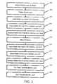
- FIG. 1is a flow diagram illustrating a conventional process for etching a semiconductor wafer to form the memory gate stack 10 of FIG. 2 .
- the memory gate 10includes therein a suitable semiconductor substate 52 having a top surface 54 and a gate stack 70 .
- the gate stackincludes a tunnel oxide layer 56 (i.e., a standard-K dielectric layer) which separates a floating gate 58 firm the substrate 52 .
- tunnel oxide layer 56i.e., a standard-K dielectric layer
- An interpoly dielectric 60separates the floating gate 58 from a control gate 62 .
- the floating gate 58 and the control gate 62are each electrically conductive and typically formed of polysilicon.
- a silicide layer 64On top of the control gate 62 is a silicide layer 64 , which acts to increase the electrical conductivity of control gate 62 .
- the silicide layer 64is typically a tungsten silicide (e.g., WSi 2 ), that is formed on top of the control gate 62 prior to patterning, using conventional deposition and annealing processes.
- step 10the multi-layer semiconductor wafer including the polysilicon layer 58 , the ONO layer 60 , the polysilicon layer 62 , the silicide layer 64 , and an oxide cap layer 66 overlying the silicide layer is covered with a photoresist layer.
- the oxide cap layer 66is optional and need not be included if so desired.
- the photoresist layeris patterned in step 12 to form a mask to form the memory gate in step 12 .
- the semiconductor waferis then inserted into an oxide etch chamber in step 14 , and an oxide etching operation is performed on the regions of the silicon oxynitride layer 66 exposed by the mask.
- the semiconductor waferis then moved in step 16 from the oxide etch chamber to a polysilicon etch chamber, where polysilicon etch processing is performed on the silicide layer 64 and the polysilicon layer 62 .
- the semiconductor waferis then removed from the polysilicon etch chamber and cleaned in step 18 to remove any remaining resist, and polymers remaining during the etching process.
- the resist and sidewalls of the etched semiconductormay be cleaned using a hydrofluoric acid dip, plus a dry plasma (O 2 ) clean, followed by a sulfuric acid bath.
- a hydrofluoric acid dipplus a dry plasma (O 2 ) clean
- another maskis formed in step 20 to cover areas that are not part of a memory core.
- the masked waferis then moved to an oxide etch chamber in step 22 for etching of the ONO layer 60 .
- the semiconductor waferis once again moved in step 24 to a polysilicon etch chamber in step 24 for etching of the polysilicon layer 58 , followed by cleaning of the mask in step 26 .
- step 28the tunnel oxide layer 56 (i.e., dielectric layer 56 ) is etched back using the gate stack 70 as a mask. It will be apparent to one of skill in the art that additional processing steps can be conducted after step 28 . However, for brevity, the discussion here of such further steps is omitted.
- tunnel layer 56is formed from a high-K dielectric material in that the removal rate of most high-K dielectric materials is lower when compared with standard-K dielectric materials (oxides) from which tunnel oxide layer 56 is formed.
- the present inventionrelates to a method for pre-treating and etching a dielectric layer in a semiconductor device comprising the steps of: (A) pre-treating one or more exposed portions of a dielectric layer with a plasma in a plasma etching tool to increase removal rate of the one or more exposed portions upon etching; and (B) removing the one or more exposed portions of the dielectric layer in the same plasma etching tool of step (A) via plasma etching.
- the present inventionrelates to a method for pre-treating and etching a dielectric layer in a semiconductor device comprising the steps of: (A) pre-treating one or more exposed portions of a high-K dielectric layer with a plasma generated by one or more gases selected from O 2 , N 2 , N 2 O, NO, HBr, He, F 2 , SF 6 plus O 2 , CH 3 F plus O 2 , or mixtures of two or more thereof, in a plasma etching tool to increase removal rate of the one or more exposed portions upon etching; and (B) removing the one or more exposed portions of the dielectric layer in the same plasma etching tool of step (A) via plasma etching with a plasma generated by one or more gases selected from HBr, F 2 , SF 6 plus O 2 , N 2 , CHF 3 plus Ar, or mixtures of two or more thereof.
- the present inventionovercomes the problem of forming a memory gate via etching in any number of different etching chambers.
- the present inventionalso provides a benefit in that plasma pre-treating the dielectric material (especially a high-K dielectric material) increases the etch rate of the dielectric material.
- FIG. 1is a flow diagram illustrating a conventional process for etching a semiconductor wafer.
- FIG. 2is a schematic cross-sectional view of a portion of a semiconductor device having a patterned conventional layer stack thereon.
- FIG. 3is a flow diagram illustrating a process for producing a semiconductor device which includes pre-treating and etch steps according to the present invention.
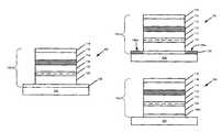
- FIG. 4is a schematic cross-sectional view of a exemplary semiconductor device (a memory gate) having a patterned stack layer that includes a polysilicon cap layer and a silicon oxynitride stop layer prior to pre-treatment and plasma etch of the dielectric layer according to one embodiment of the present invention.
- FIG. 5is a schematic cross-sectional view of a exemplary semiconductor device (a memory gate) having a patterned stack layer that includes a polysilicon cap layer and a silicon oxynitride stop layer after pre-treatment and prior to plasma etch of the dielectric layer according to one embodiment of the present invention.
- FIG. 6is a schematic cross-sectional view of a exemplary semiconductor device (a memory gate) having a patterned stack layer that includes a polysilicon cap layer and a silicon oxynitride stop layer after both the pre-treatment and plasma etch of the dielectric layer according to one embodiment of the present invention.
- standard-K dielectricrefers to a dielectric material having a K up to about 10.
- standard-K dielectric materialsinclude, for example, silicon dioxide, which has a K of about 4, silicon oxynitride, which has a K of about 4-8 depending on the relative content of oxygen and nitrogen, and silicon nitride, which has a K of about 6-9.
- mid-K dielectric materialrefers to a dielectric material having a K in the range from about 10 to about 20.
- Such mid-K dielectric materialsinclude, for example, composite materials such as hafnium silicate, which has a K of about 14, and hafnium silicon oxynitride, which has a K of about 16, depending on the relative content of oxygen and nitrogen, and hafnium silicon nitride, which has a K of about 18.
- high-K dielectricrefers to a dielectric material having a K of about 20 or more.
- high-K dielectric materialsinclude, for example, HfO 2 , ZrO 2 , Ta 2 O 5 and others identified more fully below.
- all binary and ternary metal oxides and ferroelectric materials having a K higher than about 20can be used.
- K-values or, in some cases, a range of K-valuesare shown below in Table 1 for several exemplary dielectric materials. It is understood that the present invention is not limited to the specific dielectric materials disclosed herein, but may include any appropriate standard-K and high-K dielectric materials which are known and are compatible with the remaining elements of the semiconductor device with which the dielectric materials are to be used.
- K-values, or relative permittivity, for both standard-K and high-K dielectric materialsmay vary to some degree depending on the exact nature of the dielectric material and on the process used to deposit the material. Thus, for example, differences in purity, crystallinity and stoichiometry, may give rise to variations in the exact K-value determined for any particular dielectric material.
- the materialwhen a material is referred to by a specific chemical name or formula, the material may include non-stoichiometric variations of the stoichiometrically exact formula identified by the chemical name.
- tantalum oxidewhen stoichiometrically exact, has the chemical formula Ta 2 O 5 .
- the term “tantalum oxide”may include variants of stoichiometric Ta 2 O 5 , which may be referred to as Ta x O y , in which either of x or y vary by a small amount.
- xmay vary from about 1.5 to 2.5
- ymay vary from about 4.5 to about 5.5.
- xmay vary from about 1.75 to 2.25, and y may vary from about 4 to about 6.
- ymay vary from about 4 to about 6.
- Such variations from the exact stoichiometric formulafall within the definition of tantalum oxide. Similar variations from exact stoichiometry are included when the chemical formula for a compound is used. For example, again using tantalum oxide as an example, when the formula Ta 2 O 5 is used, Ta x O y as defined above, is included within the meaning. Thus, in the present disclosure, exact stoichiometry is intended only when such is explicitly so stated. As will be understood by those of skill in the art, such variations may occur naturally, or may be sought and controlled by selection and control of the conditions under which materials are formed.
- the process of the present inventionis described herein below in terms of a common semiconductor memory gate formed on a silicon substrate. It should be noted however, that the process of the present invention can be applied to any semiconductor device where it is necessary to selectively etch a dielectric layer. In particular, the process of the present invention is well suited for applications where it is necessary to selectively etch a mid-K or high-K dielectric layer.
- a memory gate 100includes a layer stack 120 having a plurality of layers formed on a silicon substrate 102 .
- the layers 120include a tunnel layer 106 formed from a high-K dielectric material overlying on the silicon substrate 102 , a first polysilicon layer 108 overlying the tunnel layer 106 , and an oxide-nitride-oxide (ONO) layer 110 overlying the first polysilicon layer 108 .
- ONOoxide-nitride-oxide
- the stack 120also includes a second polysilicon layer 112 overlying the ONO layer 110 , a silicide (WSi x ) layer 114 overlying the second polysilicon layer 112 , a polysilicon cap layer 116 overlying the silicide layer 114 , and a silicon oxynitride (SiON) layer 118 overlying the polysilicon cap layer 116 .
- the silicon oxynitride layer 118serves as an antireflective coating (ARC) layer, and hence may be used for many reduced-size critical dimension semiconductor devices.
- Both the polysilicon cap layer 116 and the silicon oxynitride layer 118are deposited using conventional chemical vapor deposition (CVD) or plasma enhanced chemical vapor deposition (PECVD) techniques.
- the polysilicon cap layer 116typically includes undoped polysilicon and has a thickness of about 500 Angstroms.
- the silicon oxynitride layer 118includes silicon oxynitride (e.g., SiO x , N y , wherein x and y represent the atomic percentage of oxygen and nitrogen, respectively) and has a thickness of about 400 Angstroms.
- the layer stack 120is configured for submicron memory gates, and has a height of between about 3,500 Angstroms to about 5,000 Angstroms.
- the tunnel layer 106is about 50 Angstroms thick, and is thermally grown on substrate 102 .
- the polysilicon layer 108is a doped polysilicon layer formed on the tunnel layer 106 using conventional CVD or PECVD techniques to a thickness of about 900 to about 1,100 Angstroms, and is used in the memory gate as the floating polysilicon gate.
- the interpoly dielectric layer (ONO) 110is then formed overlying the polysilicon layer 108 using conventional deposition techniques to a thickness of about 150 to 200 Angstroms total.
- the ONO layer 110may be formed by a three-stage process including forming a first film of silicon dioxide on the polysilicon layer 108 , depositing a film of silicon nitride on the silicon dioxide, and then depositing a second film of silicon dioxide on the silicon nitride film.
- the polysilicon layer 112is then deposited on the ONO layer 110 to a thickness of about 1,200 Angstroms.
- the silicide layer 114is then formed using conventional silicide forming techniques to a thickness of about 1,100 to 1,700 Angstroms.
- the poly cap layer 116is then formed to a thickness of about 500 Angstroms.
- the silicon oxynitride layer 118is then deposited overlying the poly cap layer 116 .
- silicon oxynitrideas an antireflective coating layer 118
- alternative cap layer materialsmay be used that include a controllable atomic percentage of nitrogen, for example, silicon oxime.
- layer 118need not be present.
- layers 108 to 118are selectively etched in order to form the memory gate structure disclosed in FIG. 4 using, for example, a single-chamber etching process.
- a single-chamber etching processAn example of such a process is disclosed in U.S. Pat. No. 6,159,860, which is hereby incorporated herein in its entirety.
- the present inventionwill be described in relation to the above-mentioned memory gate structure, the present invention is applicable to a wide range of semiconductor devices. As noted above, the present invention is applicable to any semiconductor device in which selective etching of a dielectric layer (in particular a high-K dielectric layer) is required.
- the pre-treat (or pre-treatment) and etch steps of the present inventioncan be utilized in semiconductor devices in which photolithography is used to form one or more features/layers therein.
- the present inventioninvolves the in-situ plasma pre-treatment and etch of a tunnel layer formed from a dielectric material (in particular a high-K dielectric material).
- a dielectric materialin particular a high-K dielectric material
- the in-situ plasma pre-treatment and etchcan be utilized in the formation of any semiconductor device in which a selective etch of a dielectric layer is required.
- the in-situ plasma pre-treatment and etch process of the present inventionis advantageous in that it eliminates the need to relocate or otherwise move a semiconductor device during manufacture between different tools.
- the pre-treatment step and the plasma etch step of the present inventionare conducted in a suitable plasma etching tool.
- a suitable plasma etching toolSuch tools are known to those skilled in the art and a discussion hereof is omitted.
- the pre-treating step of the present inventioninvolves utilizing a previously patterned mask to expose selective portions of a dielectric layer to any one or more types of plasma including, but not limited to, O 2 , N 2 , N 2 O, NO, HBr, He, or fluorine chemistries suitable for use on high-K dielectric materials (e.g., F 2 , SF 6 plus O 2 , CH 3 F plus O 2 ).
- a carrier gas and/or stabilizer gassuch as Ar can be utilized in addition to the above pre-treatment plasma forming gases.
- the gas or gases used in the present invention to produce the pre-treatment plasmaare, in one embodiment, each supplied at a rate between about 25 and about 300 sccm, or at a rate of between about 50 and about 250 sccm, or even at a rate of between about 100 and about 200 sccm.
- the Ar gasif desired, is in one embodiment supplied at a rate of about 200 sccm or less, or about 100 sccm or less, or at a rate of about 50 sccm or less, or even not at all (i.e., 0 sccm).
- the gas or gases used in the present invention to produce the pretreatment plasmaare, in one embodiment, each supplied at a rate between about 20 and about 60 sccm, or at a rate of between about 30 and about 50 sccm, or even at a rate of between about 35 and about 45 sccm.
- the gas or gases used in the present invention to produce the pre-treatment plasmaare, in one embodiment, each supplied at a rate between about 5 and about 30 sccm, or at a rate of between about 7 and about 20 sccm, or even at a rate of between about 10 and about 15 sccm.
- each gascan be supplied at different rates dependent upon the dielectric material to be treated.
- the pre-treatment processis conducted for about 10 to about 600 seconds, or from about 25 to about 400 seconds, or even from about 50 to about 200 seconds.
- the amount of time for the pre-treatment step of the present inventiondepends, in part, upon the thickness of the layer to be pre-treated. It should be noted that the pre-treatment step of the present invention is conducted for any suitable length of time, as noted above, so long as the dielectric layer is not etched.
- the exposed portions of layer 106As shown in FIG. 5 , after the pre-treatment step the exposed portions of layer 106 , the exposed portions thereof, as denoted by the hatched areas 106 a , have been chemically altered so as to be more easily removed by the etch step described below.
- the semiconductor deviceAfter completion of the above-described pre-treatment step to increase the removal rate of the desired portions of layer 106 , the semiconductor device is subjected to a plasma etch in the same plasma etching tool as used for the pre-treatment step.
- the etch stepseeks to remove the portions 106 a of layer 106 .
- Thiscan be accomplished using a variety of etch chemistries.
- portions 106 acan be removed via etching with one or more types of plasma including, but not limited to, HBr, F 2 , SF 6 plus O 2 , N 2 , and CHF 3 plus Ar.
- a carrier gas and/or stabilizer gassuch as Ar, O 2 , N 2 , N 2 O and/or NO can be utilized in addition to the above pre-treatment plasma forming gases.
- the gas or gases used in the present invention to etch portions 106 a of layer 106are, in one embodiment, each supplied at a rate between about 25 and about 300 sccm, or at a rate of between about 50 and about 250 sccm, or even at a rate of between about 100 and about 200 sccm.
- the carrier gasif desired, is in one embodiment supplied at a rate of about 200 sccm or less, or about 100 sccm or less, or at a rate of about 50 sccm or less, or even not at all (i.e., 0 sccm).
- the gas or gases used in the present invention to etch portions 106 a of layer 106are, in one embodiment, each supplied at a rate between about 20 and about 60 sccm, or at a rate of between about 30 and about 50 sccm, or even at a rate of between about 35 and about 45 sccm.
- the gas or gases used in the present invention to etch portions 106 a of layer 106are, in one embodiment, each supplied at a rate between about 5 and about 30 sccm, or at a rate of between about 7 and about 20 sccm, or even at a rate of between about 10 and about 15 sccm.
- each gascan be supplied at different rates dependent upon the dielectric material to be treated.
- the etch stepis conducted for about 10 to about 600 seconds, or from about 25 to about 400 seconds, or even from about 50 to about 200 seconds.
- the amount of time for the etch step of the present inventiondepends, in part, upon the thickness of the portions 106 a of layer 106 to be removed. It should be noted that the etch step of the present invention is conducted for any suitable length of time, as noted above, so long as the desired portions of layer 106 are suitably removed.
- steps 200 to 216are identical to steps 10 to 26 described above with regard to FIG. 1 .
- the present inventiondiffers from that disclosed in FIG. 1 in that steps 218 is the above-described pre-treatment step which results in the chemical alteration of any exposed portion of dielectric material and step 220 is the above-described etch step.
- steps 218is followed by step 220 (the etch step) using any of the above-described pre-treat/etch chemistries.
- the portions 106 a of dielectric layer 106have been removed to yield dielectric layer 106 b .
- the resulting semiconductor devicecan be further processed as is known in the art.
Landscapes
- Engineering & Computer Science (AREA)
- Chemical & Material Sciences (AREA)
- Condensed Matter Physics & Semiconductors (AREA)
- Inorganic Chemistry (AREA)
- Physics & Mathematics (AREA)
- General Chemical & Material Sciences (AREA)
- Chemical Kinetics & Catalysis (AREA)
- General Physics & Mathematics (AREA)
- Manufacturing & Machinery (AREA)
- Computer Hardware Design (AREA)
- Microelectronics & Electronic Packaging (AREA)
- Power Engineering (AREA)
- Drying Of Semiconductors (AREA)
- Semiconductor Memories (AREA)
Abstract
Description
| TABLE 1 | |||
| Dielectric Constant (K) | |||
| Dielectric Material | (Relative Permittivity) | ||
| silicon dioxide | 3.9 | ||
| silicon nitride | 6-9 | ||
| silicon oxynitride | 4-8 | ||
| 12 | |||
| hafnium silicate | 15 | ||
| lanthanum oxide, La2O3 | 20-30 | ||
| hafnium oxide, HfO2 | 40 | ||
| zirconium oxide, ZrO2 | 25 | ||
| cesium oxide, CeO2 | 26 | ||
| bismuth silicon oxide, Bi4Si2O12 | 35-75 | ||
| titanium dioxide, TiO2 | 30 | ||
| tantalum oxide, Ta2 | 26 | ||
| tungsten oxide, WO3 | 42 | ||
| yttrium oxide, Y2O3 | 20 | ||
| BST (Ba1−xSrxTiO3) | ˜20-˜200 | ||
| barium strontium oxide (Ba1−xSrxO3) | ˜20-˜200 | ||
| PST (PbScxTa1−xO3) | ˜3000 | ||
| PZN (PbZnxNb1−xO3) | ˜7000 | ||
| PZT (PbZrxTi1−xO3) | ˜150-˜600 | ||
Claims (20)
Priority Applications (1)
| Application Number | Priority Date | Filing Date | Title |
|---|---|---|---|
| US10/331,938US6905971B1 (en) | 2001-12-28 | 2002-12-30 | Treatment of dielectric material to enhance etch rate |
Applications Claiming Priority (2)
| Application Number | Priority Date | Filing Date | Title |
|---|---|---|---|
| US34419101P | 2001-12-28 | 2001-12-28 | |
| US10/331,938US6905971B1 (en) | 2001-12-28 | 2002-12-30 | Treatment of dielectric material to enhance etch rate |
Publications (1)
| Publication Number | Publication Date |
|---|---|
| US6905971B1true US6905971B1 (en) | 2005-06-14 |
Family
ID=34636072
Family Applications (1)
| Application Number | Title | Priority Date | Filing Date |
|---|---|---|---|
| US10/331,938Expired - LifetimeUS6905971B1 (en) | 2001-12-28 | 2002-12-30 | Treatment of dielectric material to enhance etch rate |
Country Status (1)
| Country | Link |
|---|---|
| US (1) | US6905971B1 (en) |
Cited By (3)
| Publication number | Priority date | Publication date | Assignee | Title |
|---|---|---|---|---|
| US20070166986A1 (en)* | 2005-12-29 | 2007-07-19 | Jong Soon Lee | Semiconductor device and metal line fabrication method of the same |
| US20070170853A1 (en)* | 2000-08-28 | 2007-07-26 | Semiconductor Energy Laboratory Co., Ltd. | Light emitting device |
| US20070264825A1 (en)* | 2004-10-13 | 2007-11-15 | Semiconductor Energy Laboratory Co., Ltd. | Etching Method and Manufacturing Method of Semiconductor Device |
Citations (11)
| Publication number | Priority date | Publication date | Assignee | Title |
|---|---|---|---|---|
| US5942446A (en)* | 1997-09-12 | 1999-08-24 | Taiwan Semiconductor Manufacturing Company, Ltd. | Fluorocarbon polymer layer deposition predominant pre-etch plasma etch method for forming patterned silicon containing dielectric layer |
| US6159860A (en) | 1998-07-17 | 2000-12-12 | Advanced Micro Devices, Inc. | Method for etching layers on a semiconductor wafer in a single etching chamber |
| US6217084B1 (en) | 1996-11-21 | 2001-04-17 | Dresser Wayne Aktiebolag | Device on a conduit end and arrangement for joining conduits |
| US6225659B1 (en) | 1998-03-30 | 2001-05-01 | Advanced Micro Devices, Inc. | Trenched gate semiconductor device and method for low power applications |
| US6258675B1 (en) | 1997-12-18 | 2001-07-10 | Advanced Micro Devices, Inc. | High K gate electrode |
| US6285054B1 (en) | 1998-03-30 | 2001-09-04 | Advanced Micro Devices, Inc. | Trenched gate non-volatile semiconductor device with the source/drain regions spaced from the trench by sidewall dopings |
| US6291361B1 (en)* | 1999-03-24 | 2001-09-18 | Conexant Systems, Inc. | Method and apparatus for high-resolution in-situ plasma etching of inorganic and metal films |
| US6297167B1 (en) | 1997-09-05 | 2001-10-02 | Advanced Micro Devices, Inc. | In-situ etch of multiple layers during formation of local interconnects |
| US6297107B1 (en) | 2000-10-19 | 2001-10-02 | Advanced Micro Devices, Inc. | High dielectric constant materials as gate dielectrics |
| US6303418B1 (en) | 2000-06-30 | 2001-10-16 | Chartered Semiconductor Manufacturing Ltd. | Method of fabricating CMOS devices featuring dual gate structures and a high dielectric constant gate insulator layer |
| US6565759B1 (en)* | 1999-08-16 | 2003-05-20 | Vanguard International Semiconductor Corporation | Etching process |
- 2002
- 2002-12-30USUS10/331,938patent/US6905971B1/ennot_activeExpired - Lifetime
Patent Citations (12)
| Publication number | Priority date | Publication date | Assignee | Title |
|---|---|---|---|---|
| US6217084B1 (en) | 1996-11-21 | 2001-04-17 | Dresser Wayne Aktiebolag | Device on a conduit end and arrangement for joining conduits |
| US6297167B1 (en) | 1997-09-05 | 2001-10-02 | Advanced Micro Devices, Inc. | In-situ etch of multiple layers during formation of local interconnects |
| US5942446A (en)* | 1997-09-12 | 1999-08-24 | Taiwan Semiconductor Manufacturing Company, Ltd. | Fluorocarbon polymer layer deposition predominant pre-etch plasma etch method for forming patterned silicon containing dielectric layer |
| US6258675B1 (en) | 1997-12-18 | 2001-07-10 | Advanced Micro Devices, Inc. | High K gate electrode |
| US6225659B1 (en) | 1998-03-30 | 2001-05-01 | Advanced Micro Devices, Inc. | Trenched gate semiconductor device and method for low power applications |
| US6285054B1 (en) | 1998-03-30 | 2001-09-04 | Advanced Micro Devices, Inc. | Trenched gate non-volatile semiconductor device with the source/drain regions spaced from the trench by sidewall dopings |
| US6303437B1 (en) | 1998-03-30 | 2001-10-16 | Advanced Micro Devices, Inc. | Trenched gate semiconductor method for low power applications |
| US6159860A (en) | 1998-07-17 | 2000-12-12 | Advanced Micro Devices, Inc. | Method for etching layers on a semiconductor wafer in a single etching chamber |
| US6291361B1 (en)* | 1999-03-24 | 2001-09-18 | Conexant Systems, Inc. | Method and apparatus for high-resolution in-situ plasma etching of inorganic and metal films |
| US6565759B1 (en)* | 1999-08-16 | 2003-05-20 | Vanguard International Semiconductor Corporation | Etching process |
| US6303418B1 (en) | 2000-06-30 | 2001-10-16 | Chartered Semiconductor Manufacturing Ltd. | Method of fabricating CMOS devices featuring dual gate structures and a high dielectric constant gate insulator layer |
| US6297107B1 (en) | 2000-10-19 | 2001-10-02 | Advanced Micro Devices, Inc. | High dielectric constant materials as gate dielectrics |
Cited By (9)
| Publication number | Priority date | Publication date | Assignee | Title |
|---|---|---|---|---|
| US20070170853A1 (en)* | 2000-08-28 | 2007-07-26 | Semiconductor Energy Laboratory Co., Ltd. | Light emitting device |
| US20070264825A1 (en)* | 2004-10-13 | 2007-11-15 | Semiconductor Energy Laboratory Co., Ltd. | Etching Method and Manufacturing Method of Semiconductor Device |
| US7875506B2 (en) | 2004-10-13 | 2011-01-25 | Semiconductor Energy Laboratory Co., Ltd. | Etching method and manufacturing method of semiconductor device |
| US20110104892A1 (en)* | 2004-10-13 | 2011-05-05 | Semiconductor Energy Laboratory Co., Ltd. | Etching method and manufacturing method of semiconductor device |
| US8143168B2 (en) | 2004-10-13 | 2012-03-27 | Semiconductor Energy Laboratory Co., Ltd. | Etching method and manufacturing method of semiconductor device |
| US20070166986A1 (en)* | 2005-12-29 | 2007-07-19 | Jong Soon Lee | Semiconductor device and metal line fabrication method of the same |
| US7575998B2 (en)* | 2005-12-29 | 2009-08-18 | Dongbu Hitek Co., Ltd. | Semiconductor device and metal line fabrication method of the same |
| US20090273091A1 (en)* | 2005-12-29 | 2009-11-05 | Jong Soon Lee | Semiconductor device and metal line fabrication method of the same |
| US7994541B2 (en) | 2005-12-29 | 2011-08-09 | Dongbu Hitek Co., Ltd. | Semiconductor device and metal line fabrication method of the same |
Similar Documents
| Publication | Publication Date | Title |
|---|---|---|
| US6764898B1 (en) | Implantation into high-K dielectric material after gate etch to facilitate removal | |
| US6451647B1 (en) | Integrated plasma etch of gate and gate dielectric and low power plasma post gate etch removal of high-K residual | |
| US6960541B2 (en) | Process for fabrication of a semiconductor component having a tungsten oxide layer | |
| US6630383B1 (en) | Bi-layer floating gate for improved work function between floating gate and a high-K dielectric layer | |
| US6563183B1 (en) | Gate array with multiple dielectric properties and method for forming same | |
| US6787421B2 (en) | Method for forming a dual gate oxide device using a metal oxide and resulting device | |
| US6852645B2 (en) | High temperature interface layer growth for high-k gate dielectric | |
| US6682973B1 (en) | Formation of well-controlled thin SiO, SiN, SiON layer for multilayer high-K dielectric applications | |
| EP1124262B1 (en) | Integrated circuit comprising a multilayer dielectric stack and method | |
| US7217607B2 (en) | Method for manufacturing semiconductor integrated circuit device | |
| US7390719B2 (en) | Method of manufacturing a semiconductor device having a dual gate structure | |
| US20040070036A1 (en) | ULSI MOS with high dielectric constant gate insulator | |
| US20060125026A1 (en) | Semiconductor device with high-k dielectric layer | |
| US6693004B1 (en) | Interfacial barrier layer in semiconductor devices with high-K gate dielectric material | |
| US8557651B2 (en) | Method of manufacturing a semiconductor device using an etchant | |
| US7323419B2 (en) | Method of fabricating semiconductor device | |
| US6905971B1 (en) | Treatment of dielectric material to enhance etch rate | |
| US20020149042A1 (en) | Transistor type ferroelectric body nonvolatile storage element and method of fabricating the same | |
| US20060079075A1 (en) | Gate structures with silicide sidewall barriers and methods of manufacturing the same | |
| US6762454B1 (en) | Stacked polysilicon layer for boron penetration inhibition | |
| US12191377B2 (en) | Method for forming a semiconductor structure | |
| US6413787B1 (en) | Method for fabricating dielectric film | |
| JPWO2004073072A1 (en) | MIS type semiconductor device and method for manufacturing MIS type semiconductor device | |
| KR100275116B1 (en) | Method for forming capacitor of semiconductor device | |
| KR20030058043A (en) | Forming method for capacitor of semiconductor device |
Legal Events
| Date | Code | Title | Description |
|---|---|---|---|
| AS | Assignment | Owner name:ADVANCED MICRO DEVICES, INC., CALIFORNIA Free format text:ASSIGNMENT OF ASSIGNORS INTEREST;ASSIGNORS:TABERY, CYRUS;YANG, CHIH-YUH;EN, WILLIAM G.;AND OTHERS;REEL/FRAME:013509/0416;SIGNING DATES FROM 20030306 TO 20030317 | |
| FEPP | Fee payment procedure | Free format text:PAYOR NUMBER ASSIGNED (ORIGINAL EVENT CODE: ASPN); ENTITY STATUS OF PATENT OWNER: LARGE ENTITY | |
| STCF | Information on status: patent grant | Free format text:PATENTED CASE | |
| CC | Certificate of correction | ||
| AS | Assignment | Owner name:SPANSION INC., CALIFORNIA Free format text:ASSIGNMENT OF ASSIGNORS INTEREST;ASSIGNOR:ADVANCED MICRO DEVICES, INC.;REEL/FRAME:019047/0566 Effective date:20070131 | |
| AS | Assignment | Owner name:SPANSION LLC, CALIFORNIA Free format text:ASSIGNMENT OF ASSIGNORS INTEREST;ASSIGNOR:SPANSION INC.;REEL/FRAME:019069/0336 Effective date:20070131 | |
| FPAY | Fee payment | Year of fee payment:4 | |
| AS | Assignment | Owner name:BARCLAYS BANK PLC,NEW YORK Free format text:SECURITY AGREEMENT;ASSIGNORS:SPANSION LLC;SPANSION INC.;SPANSION TECHNOLOGY INC.;AND OTHERS;REEL/FRAME:024522/0338 Effective date:20100510 Owner name:BARCLAYS BANK PLC, NEW YORK Free format text:SECURITY AGREEMENT;ASSIGNORS:SPANSION LLC;SPANSION INC.;SPANSION TECHNOLOGY INC.;AND OTHERS;REEL/FRAME:024522/0338 Effective date:20100510 | |
| FPAY | Fee payment | Year of fee payment:8 | |
| AS | Assignment | Owner name:SPANSION TECHNOLOGY LLC, CALIFORNIA Free format text:RELEASE BY SECURED PARTY;ASSIGNOR:BARCLAYS BANK PLC;REEL/FRAME:035201/0159 Effective date:20150312 Owner name:SPANSION LLC, CALIFORNIA Free format text:RELEASE BY SECURED PARTY;ASSIGNOR:BARCLAYS BANK PLC;REEL/FRAME:035201/0159 Effective date:20150312 Owner name:SPANSION INC., CALIFORNIA Free format text:RELEASE BY SECURED PARTY;ASSIGNOR:BARCLAYS BANK PLC;REEL/FRAME:035201/0159 Effective date:20150312 | |
| AS | Assignment | Owner name:MORGAN STANLEY SENIOR FUNDING, INC., NEW YORK Free format text:SECURITY INTEREST;ASSIGNORS:CYPRESS SEMICONDUCTOR CORPORATION;SPANSION LLC;REEL/FRAME:035240/0429 Effective date:20150312 | |
| AS | Assignment | Owner name:CYPRESS SEMICONDUCTOR CORPORATION, CALIFORNIA Free format text:ASSIGNMENT OF ASSIGNORS INTEREST;ASSIGNOR:SPANSION, LLC;REEL/FRAME:036037/0495 Effective date:20150601 | |
| REMI | Maintenance fee reminder mailed | ||
| FPAY | Fee payment | Year of fee payment:12 | |
| SULP | Surcharge for late payment | Year of fee payment:11 | |
| AS | Assignment | Owner name:CYPRESS SEMICONDUCTOR CORPORATION, CALIFORNIA Free format text:RELEASE BY SECURED PARTY;ASSIGNOR:MORGAN STANLEY SENIOR FUNDING, INC.;REEL/FRAME:043062/0183 Effective date:20170628 | |
| AS | Assignment | Owner name:MONTEREY RESEARCH, LLC, CALIFORNIA Free format text:ASSIGNMENT OF ASSIGNORS INTEREST;ASSIGNOR:CYPRESS SEMICONDUCTOR CORPORATION;REEL/FRAME:043218/0017 Effective date:20170628 | |
| AS | Assignment | Owner name:MORGAN STANLEY SENIOR FUNDING, INC., NEW YORK Free format text:CORRECTIVE ASSIGNMENT TO CORRECT THE 8647899 PREVIOUSLY RECORDED ON REEL 035240 FRAME 0429. ASSIGNOR(S) HEREBY CONFIRMS THE SECURITY INTERST;ASSIGNORS:CYPRESS SEMICONDUCTOR CORPORATION;SPANSION LLC;REEL/FRAME:058002/0470 Effective date:20150312 |