US6905512B2 - System for stabilizing the vertebral column including deployment instruments and variable expansion inserts therefore - Google Patents
System for stabilizing the vertebral column including deployment instruments and variable expansion inserts thereforeDownload PDFInfo
- Publication number
- US6905512B2 US6905512B2US10/174,362US17436202AUS6905512B2US 6905512 B2US6905512 B2US 6905512B2US 17436202 AUS17436202 AUS 17436202AUS 6905512 B2US6905512 B2US 6905512B2
- Authority
- US
- United States
- Prior art keywords
- insert
- end portion
- expandable insert
- expandable
- slots
- Prior art date
- Legal status (The legal status is an assumption and is not a legal conclusion. Google has not performed a legal analysis and makes no representation as to the accuracy of the status listed.)
- Expired - Fee Related, expires
Links
- 230000000087stabilizing effectEffects0.000titleclaimsabstractdescription23
- 210000000988bone and boneAnatomy0.000claimsabstractdescription34
- 210000003041ligamentAnatomy0.000claimsabstractdescription14
- 230000001054cortical effectEffects0.000claimsabstractdescription13
- 238000002271resectionMethods0.000claimsabstractdescription5
- 238000010079rubber tappingMethods0.000claimsdescription15
- 230000006641stabilisationEffects0.000description11
- 238000011105stabilizationMethods0.000description11
- 238000013459approachMethods0.000description4
- 238000010276constructionMethods0.000description4
- 210000005036nerveAnatomy0.000description4
- 230000000694effectsEffects0.000description3
- 239000007943implantSubstances0.000description3
- 238000003780insertionMethods0.000description3
- 230000037431insertionEffects0.000description3
- 239000000463materialSubstances0.000description3
- 238000001356surgical procedureMethods0.000description3
- 238000012800visualizationMethods0.000description3
- 210000003484anatomyAnatomy0.000description2
- 230000015572biosynthetic processEffects0.000description2
- 230000008468bone growthEffects0.000description2
- 230000003902lesionEffects0.000description2
- 230000001045lordotic effectEffects0.000description2
- 239000007858starting materialSubstances0.000description2
- 230000000472traumatic effectEffects0.000description2
- RTAQQCXQSZGOHL-UHFFFAOYSA-NTitaniumChemical compound[Ti]RTAQQCXQSZGOHL-UHFFFAOYSA-N0.000description1
- 239000000956alloySubstances0.000description1
- 229910045601alloyInorganic materials0.000description1
- 238000009412basement excavationMethods0.000description1
- 239000000560biocompatible materialSubstances0.000description1
- 238000004891communicationMethods0.000description1
- 230000006378damageEffects0.000description1
- 230000006837decompressionEffects0.000description1
- 230000003111delayed effectEffects0.000description1
- 230000000368destabilizing effectEffects0.000description1
- 238000006073displacement reactionMethods0.000description1
- 238000005553drillingMethods0.000description1
- 238000000605extractionMethods0.000description1
- 230000004927fusionEffects0.000description1
- 208000014674injuryDiseases0.000description1
- 230000002262irrigationEffects0.000description1
- 238000003973irrigationMethods0.000description1
- 210000004705lumbosacral regionAnatomy0.000description1
- 230000013011matingEffects0.000description1
- 238000000034methodMethods0.000description1
- 238000012978minimally invasive surgical procedureMethods0.000description1
- 239000002245particleSubstances0.000description1
- 229910052719titaniumInorganic materials0.000description1
- 239000010936titaniumSubstances0.000description1
- 230000008736traumatic injuryEffects0.000description1
Images


Classifications
- A—HUMAN NECESSITIES
- A61—MEDICAL OR VETERINARY SCIENCE; HYGIENE
- A61F—FILTERS IMPLANTABLE INTO BLOOD VESSELS; PROSTHESES; DEVICES PROVIDING PATENCY TO, OR PREVENTING COLLAPSING OF, TUBULAR STRUCTURES OF THE BODY, e.g. STENTS; ORTHOPAEDIC, NURSING OR CONTRACEPTIVE DEVICES; FOMENTATION; TREATMENT OR PROTECTION OF EYES OR EARS; BANDAGES, DRESSINGS OR ABSORBENT PADS; FIRST-AID KITS
- A61F2/00—Filters implantable into blood vessels; Prostheses, i.e. artificial substitutes or replacements for parts of the body; Appliances for connecting them with the body; Devices providing patency to, or preventing collapsing of, tubular structures of the body, e.g. stents
- A61F2/02—Prostheses implantable into the body
- A61F2/30—Joints
- A61F2/44—Joints for the spine, e.g. vertebrae, spinal discs
- A61F2/442—Intervertebral or spinal discs, e.g. resilient
- A—HUMAN NECESSITIES
- A61—MEDICAL OR VETERINARY SCIENCE; HYGIENE
- A61B—DIAGNOSIS; SURGERY; IDENTIFICATION
- A61B17/00—Surgical instruments, devices or methods
- A61B17/56—Surgical instruments or methods for treatment of bones or joints; Devices specially adapted therefor
- A61B17/58—Surgical instruments or methods for treatment of bones or joints; Devices specially adapted therefor for osteosynthesis, e.g. bone plates, screws or setting implements
- A61B17/68—Internal fixation devices, including fasteners and spinal fixators, even if a part thereof projects from the skin
- A61B17/84—Fasteners therefor or fasteners being internal fixation devices
- A61B17/86—Pins or screws or threaded wires; nuts therefor
- A61B17/8605—Heads, i.e. proximal ends projecting from bone
- A61B17/861—Heads, i.e. proximal ends projecting from bone specially shaped for gripping driver
- A61B17/8615—Heads, i.e. proximal ends projecting from bone specially shaped for gripping driver at the central region of the screw head
- A—HUMAN NECESSITIES
- A61—MEDICAL OR VETERINARY SCIENCE; HYGIENE
- A61F—FILTERS IMPLANTABLE INTO BLOOD VESSELS; PROSTHESES; DEVICES PROVIDING PATENCY TO, OR PREVENTING COLLAPSING OF, TUBULAR STRUCTURES OF THE BODY, e.g. STENTS; ORTHOPAEDIC, NURSING OR CONTRACEPTIVE DEVICES; FOMENTATION; TREATMENT OR PROTECTION OF EYES OR EARS; BANDAGES, DRESSINGS OR ABSORBENT PADS; FIRST-AID KITS
- A61F2/00—Filters implantable into blood vessels; Prostheses, i.e. artificial substitutes or replacements for parts of the body; Appliances for connecting them with the body; Devices providing patency to, or preventing collapsing of, tubular structures of the body, e.g. stents
- A61F2/02—Prostheses implantable into the body
- A61F2/30—Joints
- A61F2/44—Joints for the spine, e.g. vertebrae, spinal discs
- A61F2/4455—Joints for the spine, e.g. vertebrae, spinal discs for the fusion of spinal bodies, e.g. intervertebral fusion of adjacent spinal bodies, e.g. fusion cages
- A61F2/446—Joints for the spine, e.g. vertebrae, spinal discs for the fusion of spinal bodies, e.g. intervertebral fusion of adjacent spinal bodies, e.g. fusion cages having a circular or elliptical cross-section substantially parallel to the axis of the spine, e.g. cylinders or frustocones
- A—HUMAN NECESSITIES
- A61—MEDICAL OR VETERINARY SCIENCE; HYGIENE
- A61F—FILTERS IMPLANTABLE INTO BLOOD VESSELS; PROSTHESES; DEVICES PROVIDING PATENCY TO, OR PREVENTING COLLAPSING OF, TUBULAR STRUCTURES OF THE BODY, e.g. STENTS; ORTHOPAEDIC, NURSING OR CONTRACEPTIVE DEVICES; FOMENTATION; TREATMENT OR PROTECTION OF EYES OR EARS; BANDAGES, DRESSINGS OR ABSORBENT PADS; FIRST-AID KITS
- A61F2/00—Filters implantable into blood vessels; Prostheses, i.e. artificial substitutes or replacements for parts of the body; Appliances for connecting them with the body; Devices providing patency to, or preventing collapsing of, tubular structures of the body, e.g. stents
- A61F2/02—Prostheses implantable into the body
- A61F2/30—Joints
- A61F2/46—Special tools for implanting artificial joints
- A61F2/4603—Special tools for implanting artificial joints for insertion or extraction of endoprosthetic joints or of accessories thereof
- A61F2/4611—Special tools for implanting artificial joints for insertion or extraction of endoprosthetic joints or of accessories thereof of spinal prostheses
- A—HUMAN NECESSITIES
- A61—MEDICAL OR VETERINARY SCIENCE; HYGIENE
- A61F—FILTERS IMPLANTABLE INTO BLOOD VESSELS; PROSTHESES; DEVICES PROVIDING PATENCY TO, OR PREVENTING COLLAPSING OF, TUBULAR STRUCTURES OF THE BODY, e.g. STENTS; ORTHOPAEDIC, NURSING OR CONTRACEPTIVE DEVICES; FOMENTATION; TREATMENT OR PROTECTION OF EYES OR EARS; BANDAGES, DRESSINGS OR ABSORBENT PADS; FIRST-AID KITS
- A61F2/00—Filters implantable into blood vessels; Prostheses, i.e. artificial substitutes or replacements for parts of the body; Appliances for connecting them with the body; Devices providing patency to, or preventing collapsing of, tubular structures of the body, e.g. stents
- A61F2/02—Prostheses implantable into the body
- A61F2/30—Joints
- A61F2/46—Special tools for implanting artificial joints
- A61F2/4637—Special tools for implanting artificial joints for connecting or disconnecting two parts of a prosthesis
- A—HUMAN NECESSITIES
- A61—MEDICAL OR VETERINARY SCIENCE; HYGIENE
- A61B—DIAGNOSIS; SURGERY; IDENTIFICATION
- A61B17/00—Surgical instruments, devices or methods
- A61B17/56—Surgical instruments or methods for treatment of bones or joints; Devices specially adapted therefor
- A61B17/58—Surgical instruments or methods for treatment of bones or joints; Devices specially adapted therefor for osteosynthesis, e.g. bone plates, screws or setting implements
- A61B17/88—Osteosynthesis instruments; Methods or means for implanting or extracting internal or external fixation devices
- A61B17/8875—Screwdrivers, spanners or wrenches
- A61B17/8877—Screwdrivers, spanners or wrenches characterised by the cross-section of the driver bit
- A61B17/888—Screwdrivers, spanners or wrenches characterised by the cross-section of the driver bit the driver bit acting on the central region of the screw head
- A—HUMAN NECESSITIES
- A61—MEDICAL OR VETERINARY SCIENCE; HYGIENE
- A61F—FILTERS IMPLANTABLE INTO BLOOD VESSELS; PROSTHESES; DEVICES PROVIDING PATENCY TO, OR PREVENTING COLLAPSING OF, TUBULAR STRUCTURES OF THE BODY, e.g. STENTS; ORTHOPAEDIC, NURSING OR CONTRACEPTIVE DEVICES; FOMENTATION; TREATMENT OR PROTECTION OF EYES OR EARS; BANDAGES, DRESSINGS OR ABSORBENT PADS; FIRST-AID KITS
- A61F2/00—Filters implantable into blood vessels; Prostheses, i.e. artificial substitutes or replacements for parts of the body; Appliances for connecting them with the body; Devices providing patency to, or preventing collapsing of, tubular structures of the body, e.g. stents
- A61F2/02—Prostheses implantable into the body
- A61F2/30—Joints
- A61F2/46—Special tools for implanting artificial joints
- A61F2/4603—Special tools for implanting artificial joints for insertion or extraction of endoprosthetic joints or of accessories thereof
- A—HUMAN NECESSITIES
- A61—MEDICAL OR VETERINARY SCIENCE; HYGIENE
- A61F—FILTERS IMPLANTABLE INTO BLOOD VESSELS; PROSTHESES; DEVICES PROVIDING PATENCY TO, OR PREVENTING COLLAPSING OF, TUBULAR STRUCTURES OF THE BODY, e.g. STENTS; ORTHOPAEDIC, NURSING OR CONTRACEPTIVE DEVICES; FOMENTATION; TREATMENT OR PROTECTION OF EYES OR EARS; BANDAGES, DRESSINGS OR ABSORBENT PADS; FIRST-AID KITS
- A61F2/00—Filters implantable into blood vessels; Prostheses, i.e. artificial substitutes or replacements for parts of the body; Appliances for connecting them with the body; Devices providing patency to, or preventing collapsing of, tubular structures of the body, e.g. stents
- A61F2/02—Prostheses implantable into the body
- A61F2/30—Joints
- A61F2002/30001—Additional features of subject-matter classified in A61F2/28, A61F2/30 and subgroups thereof
- A61F2002/30108—Shapes
- A61F2002/3011—Cross-sections or two-dimensional shapes
- A61F2002/30138—Convex polygonal shapes
- A61F2002/30154—Convex polygonal shapes square
- A—HUMAN NECESSITIES
- A61—MEDICAL OR VETERINARY SCIENCE; HYGIENE
- A61F—FILTERS IMPLANTABLE INTO BLOOD VESSELS; PROSTHESES; DEVICES PROVIDING PATENCY TO, OR PREVENTING COLLAPSING OF, TUBULAR STRUCTURES OF THE BODY, e.g. STENTS; ORTHOPAEDIC, NURSING OR CONTRACEPTIVE DEVICES; FOMENTATION; TREATMENT OR PROTECTION OF EYES OR EARS; BANDAGES, DRESSINGS OR ABSORBENT PADS; FIRST-AID KITS
- A61F2/00—Filters implantable into blood vessels; Prostheses, i.e. artificial substitutes or replacements for parts of the body; Appliances for connecting them with the body; Devices providing patency to, or preventing collapsing of, tubular structures of the body, e.g. stents
- A61F2/02—Prostheses implantable into the body
- A61F2/30—Joints
- A61F2002/30001—Additional features of subject-matter classified in A61F2/28, A61F2/30 and subgroups thereof
- A61F2002/30108—Shapes
- A61F2002/30199—Three-dimensional shapes
- A61F2002/30224—Three-dimensional shapes cylindrical
- A61F2002/30235—Three-dimensional shapes cylindrical tubular, e.g. sleeves
- A—HUMAN NECESSITIES
- A61—MEDICAL OR VETERINARY SCIENCE; HYGIENE
- A61F—FILTERS IMPLANTABLE INTO BLOOD VESSELS; PROSTHESES; DEVICES PROVIDING PATENCY TO, OR PREVENTING COLLAPSING OF, TUBULAR STRUCTURES OF THE BODY, e.g. STENTS; ORTHOPAEDIC, NURSING OR CONTRACEPTIVE DEVICES; FOMENTATION; TREATMENT OR PROTECTION OF EYES OR EARS; BANDAGES, DRESSINGS OR ABSORBENT PADS; FIRST-AID KITS
- A61F2/00—Filters implantable into blood vessels; Prostheses, i.e. artificial substitutes or replacements for parts of the body; Appliances for connecting them with the body; Devices providing patency to, or preventing collapsing of, tubular structures of the body, e.g. stents
- A61F2/02—Prostheses implantable into the body
- A61F2/30—Joints
- A61F2002/30001—Additional features of subject-matter classified in A61F2/28, A61F2/30 and subgroups thereof
- A61F2002/30316—The prosthesis having different structural features at different locations within the same prosthesis; Connections between prosthetic parts; Special structural features of bone or joint prostheses not otherwise provided for
- A61F2002/30329—Connections or couplings between prosthetic parts, e.g. between modular parts; Connecting elements
- A61F2002/30405—Connections or couplings between prosthetic parts, e.g. between modular parts; Connecting elements made by screwing complementary threads machined on the parts themselves
- A61F2002/30408—Conical threadings
- A—HUMAN NECESSITIES
- A61—MEDICAL OR VETERINARY SCIENCE; HYGIENE
- A61F—FILTERS IMPLANTABLE INTO BLOOD VESSELS; PROSTHESES; DEVICES PROVIDING PATENCY TO, OR PREVENTING COLLAPSING OF, TUBULAR STRUCTURES OF THE BODY, e.g. STENTS; ORTHOPAEDIC, NURSING OR CONTRACEPTIVE DEVICES; FOMENTATION; TREATMENT OR PROTECTION OF EYES OR EARS; BANDAGES, DRESSINGS OR ABSORBENT PADS; FIRST-AID KITS
- A61F2/00—Filters implantable into blood vessels; Prostheses, i.e. artificial substitutes or replacements for parts of the body; Appliances for connecting them with the body; Devices providing patency to, or preventing collapsing of, tubular structures of the body, e.g. stents
- A61F2/02—Prostheses implantable into the body
- A61F2/30—Joints
- A61F2002/30001—Additional features of subject-matter classified in A61F2/28, A61F2/30 and subgroups thereof
- A61F2002/30316—The prosthesis having different structural features at different locations within the same prosthesis; Connections between prosthetic parts; Special structural features of bone or joint prostheses not otherwise provided for
- A61F2002/30329—Connections or couplings between prosthetic parts, e.g. between modular parts; Connecting elements
- A61F2002/30476—Connections or couplings between prosthetic parts, e.g. between modular parts; Connecting elements locked by an additional locking mechanism
- A61F2002/30507—Connections or couplings between prosthetic parts, e.g. between modular parts; Connecting elements locked by an additional locking mechanism using a threaded locking member, e.g. a locking screw or a set screw
- A—HUMAN NECESSITIES
- A61—MEDICAL OR VETERINARY SCIENCE; HYGIENE
- A61F—FILTERS IMPLANTABLE INTO BLOOD VESSELS; PROSTHESES; DEVICES PROVIDING PATENCY TO, OR PREVENTING COLLAPSING OF, TUBULAR STRUCTURES OF THE BODY, e.g. STENTS; ORTHOPAEDIC, NURSING OR CONTRACEPTIVE DEVICES; FOMENTATION; TREATMENT OR PROTECTION OF EYES OR EARS; BANDAGES, DRESSINGS OR ABSORBENT PADS; FIRST-AID KITS
- A61F2/00—Filters implantable into blood vessels; Prostheses, i.e. artificial substitutes or replacements for parts of the body; Appliances for connecting them with the body; Devices providing patency to, or preventing collapsing of, tubular structures of the body, e.g. stents
- A61F2/02—Prostheses implantable into the body
- A61F2/30—Joints
- A61F2002/30001—Additional features of subject-matter classified in A61F2/28, A61F2/30 and subgroups thereof
- A61F2002/30316—The prosthesis having different structural features at different locations within the same prosthesis; Connections between prosthetic parts; Special structural features of bone or joint prostheses not otherwise provided for
- A61F2002/30535—Special structural features of bone or joint prostheses not otherwise provided for
- A61F2002/30537—Special structural features of bone or joint prostheses not otherwise provided for adjustable
- A61F2002/30538—Special structural features of bone or joint prostheses not otherwise provided for adjustable for adjusting angular orientation
- A—HUMAN NECESSITIES
- A61—MEDICAL OR VETERINARY SCIENCE; HYGIENE
- A61F—FILTERS IMPLANTABLE INTO BLOOD VESSELS; PROSTHESES; DEVICES PROVIDING PATENCY TO, OR PREVENTING COLLAPSING OF, TUBULAR STRUCTURES OF THE BODY, e.g. STENTS; ORTHOPAEDIC, NURSING OR CONTRACEPTIVE DEVICES; FOMENTATION; TREATMENT OR PROTECTION OF EYES OR EARS; BANDAGES, DRESSINGS OR ABSORBENT PADS; FIRST-AID KITS
- A61F2/00—Filters implantable into blood vessels; Prostheses, i.e. artificial substitutes or replacements for parts of the body; Appliances for connecting them with the body; Devices providing patency to, or preventing collapsing of, tubular structures of the body, e.g. stents
- A61F2/02—Prostheses implantable into the body
- A61F2/30—Joints
- A61F2002/30001—Additional features of subject-matter classified in A61F2/28, A61F2/30 and subgroups thereof
- A61F2002/30316—The prosthesis having different structural features at different locations within the same prosthesis; Connections between prosthetic parts; Special structural features of bone or joint prostheses not otherwise provided for
- A61F2002/30535—Special structural features of bone or joint prostheses not otherwise provided for
- A61F2002/30579—Special structural features of bone or joint prostheses not otherwise provided for with mechanically expandable devices, e.g. fixation devices
- A—HUMAN NECESSITIES
- A61—MEDICAL OR VETERINARY SCIENCE; HYGIENE
- A61F—FILTERS IMPLANTABLE INTO BLOOD VESSELS; PROSTHESES; DEVICES PROVIDING PATENCY TO, OR PREVENTING COLLAPSING OF, TUBULAR STRUCTURES OF THE BODY, e.g. STENTS; ORTHOPAEDIC, NURSING OR CONTRACEPTIVE DEVICES; FOMENTATION; TREATMENT OR PROTECTION OF EYES OR EARS; BANDAGES, DRESSINGS OR ABSORBENT PADS; FIRST-AID KITS
- A61F2/00—Filters implantable into blood vessels; Prostheses, i.e. artificial substitutes or replacements for parts of the body; Appliances for connecting them with the body; Devices providing patency to, or preventing collapsing of, tubular structures of the body, e.g. stents
- A61F2/02—Prostheses implantable into the body
- A61F2/30—Joints
- A61F2002/30001—Additional features of subject-matter classified in A61F2/28, A61F2/30 and subgroups thereof
- A61F2002/30316—The prosthesis having different structural features at different locations within the same prosthesis; Connections between prosthetic parts; Special structural features of bone or joint prostheses not otherwise provided for
- A61F2002/30535—Special structural features of bone or joint prostheses not otherwise provided for
- A61F2002/30593—Special structural features of bone or joint prostheses not otherwise provided for hollow
- A—HUMAN NECESSITIES
- A61—MEDICAL OR VETERINARY SCIENCE; HYGIENE
- A61F—FILTERS IMPLANTABLE INTO BLOOD VESSELS; PROSTHESES; DEVICES PROVIDING PATENCY TO, OR PREVENTING COLLAPSING OF, TUBULAR STRUCTURES OF THE BODY, e.g. STENTS; ORTHOPAEDIC, NURSING OR CONTRACEPTIVE DEVICES; FOMENTATION; TREATMENT OR PROTECTION OF EYES OR EARS; BANDAGES, DRESSINGS OR ABSORBENT PADS; FIRST-AID KITS
- A61F2/00—Filters implantable into blood vessels; Prostheses, i.e. artificial substitutes or replacements for parts of the body; Appliances for connecting them with the body; Devices providing patency to, or preventing collapsing of, tubular structures of the body, e.g. stents
- A61F2/02—Prostheses implantable into the body
- A61F2/30—Joints
- A61F2002/30001—Additional features of subject-matter classified in A61F2/28, A61F2/30 and subgroups thereof
- A61F2002/30316—The prosthesis having different structural features at different locations within the same prosthesis; Connections between prosthetic parts; Special structural features of bone or joint prostheses not otherwise provided for
- A61F2002/30535—Special structural features of bone or joint prostheses not otherwise provided for
- A61F2002/30594—Special structural features of bone or joint prostheses not otherwise provided for slotted, e.g. radial or meridian slot ending in a polar aperture, non-polar slots, horizontal or arcuate slots
- A—HUMAN NECESSITIES
- A61—MEDICAL OR VETERINARY SCIENCE; HYGIENE
- A61F—FILTERS IMPLANTABLE INTO BLOOD VESSELS; PROSTHESES; DEVICES PROVIDING PATENCY TO, OR PREVENTING COLLAPSING OF, TUBULAR STRUCTURES OF THE BODY, e.g. STENTS; ORTHOPAEDIC, NURSING OR CONTRACEPTIVE DEVICES; FOMENTATION; TREATMENT OR PROTECTION OF EYES OR EARS; BANDAGES, DRESSINGS OR ABSORBENT PADS; FIRST-AID KITS
- A61F2/00—Filters implantable into blood vessels; Prostheses, i.e. artificial substitutes or replacements for parts of the body; Appliances for connecting them with the body; Devices providing patency to, or preventing collapsing of, tubular structures of the body, e.g. stents
- A61F2/02—Prostheses implantable into the body
- A61F2/30—Joints
- A61F2002/30001—Additional features of subject-matter classified in A61F2/28, A61F2/30 and subgroups thereof
- A61F2002/30316—The prosthesis having different structural features at different locations within the same prosthesis; Connections between prosthetic parts; Special structural features of bone or joint prostheses not otherwise provided for
- A61F2002/30535—Special structural features of bone or joint prostheses not otherwise provided for
- A61F2002/30604—Special structural features of bone or joint prostheses not otherwise provided for modular
- A61F2002/30616—Sets comprising a plurality of prosthetic parts of different sizes or orientations
- A—HUMAN NECESSITIES
- A61—MEDICAL OR VETERINARY SCIENCE; HYGIENE
- A61F—FILTERS IMPLANTABLE INTO BLOOD VESSELS; PROSTHESES; DEVICES PROVIDING PATENCY TO, OR PREVENTING COLLAPSING OF, TUBULAR STRUCTURES OF THE BODY, e.g. STENTS; ORTHOPAEDIC, NURSING OR CONTRACEPTIVE DEVICES; FOMENTATION; TREATMENT OR PROTECTION OF EYES OR EARS; BANDAGES, DRESSINGS OR ABSORBENT PADS; FIRST-AID KITS
- A61F2/00—Filters implantable into blood vessels; Prostheses, i.e. artificial substitutes or replacements for parts of the body; Appliances for connecting them with the body; Devices providing patency to, or preventing collapsing of, tubular structures of the body, e.g. stents
- A61F2/02—Prostheses implantable into the body
- A61F2/30—Joints
- A61F2002/30001—Additional features of subject-matter classified in A61F2/28, A61F2/30 and subgroups thereof
- A61F2002/30316—The prosthesis having different structural features at different locations within the same prosthesis; Connections between prosthetic parts; Special structural features of bone or joint prostheses not otherwise provided for
- A61F2002/30535—Special structural features of bone or joint prostheses not otherwise provided for
- A61F2002/30617—Visible markings for adjusting, locating or measuring
- A—HUMAN NECESSITIES
- A61—MEDICAL OR VETERINARY SCIENCE; HYGIENE
- A61F—FILTERS IMPLANTABLE INTO BLOOD VESSELS; PROSTHESES; DEVICES PROVIDING PATENCY TO, OR PREVENTING COLLAPSING OF, TUBULAR STRUCTURES OF THE BODY, e.g. STENTS; ORTHOPAEDIC, NURSING OR CONTRACEPTIVE DEVICES; FOMENTATION; TREATMENT OR PROTECTION OF EYES OR EARS; BANDAGES, DRESSINGS OR ABSORBENT PADS; FIRST-AID KITS
- A61F2/00—Filters implantable into blood vessels; Prostheses, i.e. artificial substitutes or replacements for parts of the body; Appliances for connecting them with the body; Devices providing patency to, or preventing collapsing of, tubular structures of the body, e.g. stents
- A61F2/02—Prostheses implantable into the body
- A61F2/30—Joints
- A61F2002/30001—Additional features of subject-matter classified in A61F2/28, A61F2/30 and subgroups thereof
- A61F2002/30667—Features concerning an interaction with the environment or a particular use of the prosthesis
- A61F2002/30706—Features concerning an interaction with the environment or a particular use of the prosthesis specially designed for children, e.g. having means for adjusting to their growth
- A—HUMAN NECESSITIES
- A61—MEDICAL OR VETERINARY SCIENCE; HYGIENE
- A61F—FILTERS IMPLANTABLE INTO BLOOD VESSELS; PROSTHESES; DEVICES PROVIDING PATENCY TO, OR PREVENTING COLLAPSING OF, TUBULAR STRUCTURES OF THE BODY, e.g. STENTS; ORTHOPAEDIC, NURSING OR CONTRACEPTIVE DEVICES; FOMENTATION; TREATMENT OR PROTECTION OF EYES OR EARS; BANDAGES, DRESSINGS OR ABSORBENT PADS; FIRST-AID KITS
- A61F2/00—Filters implantable into blood vessels; Prostheses, i.e. artificial substitutes or replacements for parts of the body; Appliances for connecting them with the body; Devices providing patency to, or preventing collapsing of, tubular structures of the body, e.g. stents
- A61F2/02—Prostheses implantable into the body
- A61F2/30—Joints
- A61F2/30767—Special external or bone-contacting surface, e.g. coating for improving bone ingrowth
- A61F2/30771—Special external or bone-contacting surface, e.g. coating for improving bone ingrowth applied in original prostheses, e.g. holes or grooves
- A61F2002/30772—Apertures or holes, e.g. of circular cross section
- A—HUMAN NECESSITIES
- A61—MEDICAL OR VETERINARY SCIENCE; HYGIENE
- A61F—FILTERS IMPLANTABLE INTO BLOOD VESSELS; PROSTHESES; DEVICES PROVIDING PATENCY TO, OR PREVENTING COLLAPSING OF, TUBULAR STRUCTURES OF THE BODY, e.g. STENTS; ORTHOPAEDIC, NURSING OR CONTRACEPTIVE DEVICES; FOMENTATION; TREATMENT OR PROTECTION OF EYES OR EARS; BANDAGES, DRESSINGS OR ABSORBENT PADS; FIRST-AID KITS
- A61F2/00—Filters implantable into blood vessels; Prostheses, i.e. artificial substitutes or replacements for parts of the body; Appliances for connecting them with the body; Devices providing patency to, or preventing collapsing of, tubular structures of the body, e.g. stents
- A61F2/02—Prostheses implantable into the body
- A61F2/30—Joints
- A61F2/30767—Special external or bone-contacting surface, e.g. coating for improving bone ingrowth
- A61F2/30771—Special external or bone-contacting surface, e.g. coating for improving bone ingrowth applied in original prostheses, e.g. holes or grooves
- A61F2002/30795—Blind bores, e.g. of circular cross-section
- A61F2002/30797—Blind bores, e.g. of circular cross-section internally-threaded
- A—HUMAN NECESSITIES
- A61—MEDICAL OR VETERINARY SCIENCE; HYGIENE
- A61F—FILTERS IMPLANTABLE INTO BLOOD VESSELS; PROSTHESES; DEVICES PROVIDING PATENCY TO, OR PREVENTING COLLAPSING OF, TUBULAR STRUCTURES OF THE BODY, e.g. STENTS; ORTHOPAEDIC, NURSING OR CONTRACEPTIVE DEVICES; FOMENTATION; TREATMENT OR PROTECTION OF EYES OR EARS; BANDAGES, DRESSINGS OR ABSORBENT PADS; FIRST-AID KITS
- A61F2/00—Filters implantable into blood vessels; Prostheses, i.e. artificial substitutes or replacements for parts of the body; Appliances for connecting them with the body; Devices providing patency to, or preventing collapsing of, tubular structures of the body, e.g. stents
- A61F2/02—Prostheses implantable into the body
- A61F2/30—Joints
- A61F2/30767—Special external or bone-contacting surface, e.g. coating for improving bone ingrowth
- A61F2/30771—Special external or bone-contacting surface, e.g. coating for improving bone ingrowth applied in original prostheses, e.g. holes or grooves
- A61F2002/3085—Special external or bone-contacting surface, e.g. coating for improving bone ingrowth applied in original prostheses, e.g. holes or grooves with a threaded, e.g. self-tapping, bone-engaging surface, e.g. external surface
- A61F2002/30858—Threads interrupted by grooves or sidewalls, e.g. flat sidewalls
- A—HUMAN NECESSITIES
- A61—MEDICAL OR VETERINARY SCIENCE; HYGIENE
- A61F—FILTERS IMPLANTABLE INTO BLOOD VESSELS; PROSTHESES; DEVICES PROVIDING PATENCY TO, OR PREVENTING COLLAPSING OF, TUBULAR STRUCTURES OF THE BODY, e.g. STENTS; ORTHOPAEDIC, NURSING OR CONTRACEPTIVE DEVICES; FOMENTATION; TREATMENT OR PROTECTION OF EYES OR EARS; BANDAGES, DRESSINGS OR ABSORBENT PADS; FIRST-AID KITS
- A61F2/00—Filters implantable into blood vessels; Prostheses, i.e. artificial substitutes or replacements for parts of the body; Appliances for connecting them with the body; Devices providing patency to, or preventing collapsing of, tubular structures of the body, e.g. stents
- A61F2/02—Prostheses implantable into the body
- A61F2/30—Joints
- A61F2/30767—Special external or bone-contacting surface, e.g. coating for improving bone ingrowth
- A61F2/30771—Special external or bone-contacting surface, e.g. coating for improving bone ingrowth applied in original prostheses, e.g. holes or grooves
- A61F2002/3085—Special external or bone-contacting surface, e.g. coating for improving bone ingrowth applied in original prostheses, e.g. holes or grooves with a threaded, e.g. self-tapping, bone-engaging surface, e.g. external surface
- A61F2002/30863—Special external or bone-contacting surface, e.g. coating for improving bone ingrowth applied in original prostheses, e.g. holes or grooves with a threaded, e.g. self-tapping, bone-engaging surface, e.g. external surface the entry end surface having flutes, relief grooves, starter notches or bevelled indentations
- A—HUMAN NECESSITIES
- A61—MEDICAL OR VETERINARY SCIENCE; HYGIENE
- A61F—FILTERS IMPLANTABLE INTO BLOOD VESSELS; PROSTHESES; DEVICES PROVIDING PATENCY TO, OR PREVENTING COLLAPSING OF, TUBULAR STRUCTURES OF THE BODY, e.g. STENTS; ORTHOPAEDIC, NURSING OR CONTRACEPTIVE DEVICES; FOMENTATION; TREATMENT OR PROTECTION OF EYES OR EARS; BANDAGES, DRESSINGS OR ABSORBENT PADS; FIRST-AID KITS
- A61F2/00—Filters implantable into blood vessels; Prostheses, i.e. artificial substitutes or replacements for parts of the body; Appliances for connecting them with the body; Devices providing patency to, or preventing collapsing of, tubular structures of the body, e.g. stents
- A61F2/02—Prostheses implantable into the body
- A61F2/30—Joints
- A61F2/46—Special tools for implanting artificial joints
- A61F2002/4635—Special tools for implanting artificial joints using minimally invasive surgery
- A—HUMAN NECESSITIES
- A61—MEDICAL OR VETERINARY SCIENCE; HYGIENE
- A61F—FILTERS IMPLANTABLE INTO BLOOD VESSELS; PROSTHESES; DEVICES PROVIDING PATENCY TO, OR PREVENTING COLLAPSING OF, TUBULAR STRUCTURES OF THE BODY, e.g. STENTS; ORTHOPAEDIC, NURSING OR CONTRACEPTIVE DEVICES; FOMENTATION; TREATMENT OR PROTECTION OF EYES OR EARS; BANDAGES, DRESSINGS OR ABSORBENT PADS; FIRST-AID KITS
- A61F2/00—Filters implantable into blood vessels; Prostheses, i.e. artificial substitutes or replacements for parts of the body; Appliances for connecting them with the body; Devices providing patency to, or preventing collapsing of, tubular structures of the body, e.g. stents
- A61F2/02—Prostheses implantable into the body
- A61F2/30—Joints
- A61F2/46—Special tools for implanting artificial joints
- A61F2/4637—Special tools for implanting artificial joints for connecting or disconnecting two parts of a prosthesis
- A61F2002/4638—Tools for performing screwing, e.g. nut or screwdrivers, or particular adaptations therefor
- A—HUMAN NECESSITIES
- A61—MEDICAL OR VETERINARY SCIENCE; HYGIENE
- A61F—FILTERS IMPLANTABLE INTO BLOOD VESSELS; PROSTHESES; DEVICES PROVIDING PATENCY TO, OR PREVENTING COLLAPSING OF, TUBULAR STRUCTURES OF THE BODY, e.g. STENTS; ORTHOPAEDIC, NURSING OR CONTRACEPTIVE DEVICES; FOMENTATION; TREATMENT OR PROTECTION OF EYES OR EARS; BANDAGES, DRESSINGS OR ABSORBENT PADS; FIRST-AID KITS
- A61F2220/00—Fixations or connections for prostheses classified in groups A61F2/00 - A61F2/26 or A61F2/82 or A61F9/00 or A61F11/00 or subgroups thereof
- A61F2220/0025—Connections or couplings between prosthetic parts, e.g. between modular parts; Connecting elements
- A—HUMAN NECESSITIES
- A61—MEDICAL OR VETERINARY SCIENCE; HYGIENE
- A61F—FILTERS IMPLANTABLE INTO BLOOD VESSELS; PROSTHESES; DEVICES PROVIDING PATENCY TO, OR PREVENTING COLLAPSING OF, TUBULAR STRUCTURES OF THE BODY, e.g. STENTS; ORTHOPAEDIC, NURSING OR CONTRACEPTIVE DEVICES; FOMENTATION; TREATMENT OR PROTECTION OF EYES OR EARS; BANDAGES, DRESSINGS OR ABSORBENT PADS; FIRST-AID KITS
- A61F2230/00—Geometry of prostheses classified in groups A61F2/00 - A61F2/26 or A61F2/82 or A61F9/00 or A61F11/00 or subgroups thereof
- A61F2230/0002—Two-dimensional shapes, e.g. cross-sections
- A61F2230/0017—Angular shapes
- A61F2230/0021—Angular shapes square
- A—HUMAN NECESSITIES
- A61—MEDICAL OR VETERINARY SCIENCE; HYGIENE
- A61F—FILTERS IMPLANTABLE INTO BLOOD VESSELS; PROSTHESES; DEVICES PROVIDING PATENCY TO, OR PREVENTING COLLAPSING OF, TUBULAR STRUCTURES OF THE BODY, e.g. STENTS; ORTHOPAEDIC, NURSING OR CONTRACEPTIVE DEVICES; FOMENTATION; TREATMENT OR PROTECTION OF EYES OR EARS; BANDAGES, DRESSINGS OR ABSORBENT PADS; FIRST-AID KITS
- A61F2230/00—Geometry of prostheses classified in groups A61F2/00 - A61F2/26 or A61F2/82 or A61F9/00 or A61F11/00 or subgroups thereof
- A61F2230/0063—Three-dimensional shapes
- A61F2230/0069—Three-dimensional shapes cylindrical
- A—HUMAN NECESSITIES
- A61—MEDICAL OR VETERINARY SCIENCE; HYGIENE
- A61F—FILTERS IMPLANTABLE INTO BLOOD VESSELS; PROSTHESES; DEVICES PROVIDING PATENCY TO, OR PREVENTING COLLAPSING OF, TUBULAR STRUCTURES OF THE BODY, e.g. STENTS; ORTHOPAEDIC, NURSING OR CONTRACEPTIVE DEVICES; FOMENTATION; TREATMENT OR PROTECTION OF EYES OR EARS; BANDAGES, DRESSINGS OR ABSORBENT PADS; FIRST-AID KITS
- A61F2250/00—Special features of prostheses classified in groups A61F2/00 - A61F2/26 or A61F2/82 or A61F9/00 or A61F11/00 or subgroups thereof
- A61F2250/0004—Special features of prostheses classified in groups A61F2/00 - A61F2/26 or A61F2/82 or A61F9/00 or A61F11/00 or subgroups thereof adjustable
- A61F2250/0006—Special features of prostheses classified in groups A61F2/00 - A61F2/26 or A61F2/82 or A61F9/00 or A61F11/00 or subgroups thereof adjustable for adjusting angular orientation
- A—HUMAN NECESSITIES
- A61—MEDICAL OR VETERINARY SCIENCE; HYGIENE
- A61F—FILTERS IMPLANTABLE INTO BLOOD VESSELS; PROSTHESES; DEVICES PROVIDING PATENCY TO, OR PREVENTING COLLAPSING OF, TUBULAR STRUCTURES OF THE BODY, e.g. STENTS; ORTHOPAEDIC, NURSING OR CONTRACEPTIVE DEVICES; FOMENTATION; TREATMENT OR PROTECTION OF EYES OR EARS; BANDAGES, DRESSINGS OR ABSORBENT PADS; FIRST-AID KITS
- A61F2250/00—Special features of prostheses classified in groups A61F2/00 - A61F2/26 or A61F2/82 or A61F9/00 or A61F11/00 or subgroups thereof
- A61F2250/0058—Additional features; Implant or prostheses properties not otherwise provided for
- A61F2250/0082—Additional features; Implant or prostheses properties not otherwise provided for specially designed for children, e.g. having means for adjusting to their growth
- A—HUMAN NECESSITIES
- A61—MEDICAL OR VETERINARY SCIENCE; HYGIENE
- A61F—FILTERS IMPLANTABLE INTO BLOOD VESSELS; PROSTHESES; DEVICES PROVIDING PATENCY TO, OR PREVENTING COLLAPSING OF, TUBULAR STRUCTURES OF THE BODY, e.g. STENTS; ORTHOPAEDIC, NURSING OR CONTRACEPTIVE DEVICES; FOMENTATION; TREATMENT OR PROTECTION OF EYES OR EARS; BANDAGES, DRESSINGS OR ABSORBENT PADS; FIRST-AID KITS
- A61F2250/00—Special features of prostheses classified in groups A61F2/00 - A61F2/26 or A61F2/82 or A61F9/00 or A61F11/00 or subgroups thereof
- A61F2250/0058—Additional features; Implant or prostheses properties not otherwise provided for
- A61F2250/0096—Markers and sensors for detecting a position or changes of a position of an implant, e.g. RF sensors, ultrasound markers
- A61F2250/0097—Visible markings, e.g. indicia
- A—HUMAN NECESSITIES
- A61—MEDICAL OR VETERINARY SCIENCE; HYGIENE
- A61F—FILTERS IMPLANTABLE INTO BLOOD VESSELS; PROSTHESES; DEVICES PROVIDING PATENCY TO, OR PREVENTING COLLAPSING OF, TUBULAR STRUCTURES OF THE BODY, e.g. STENTS; ORTHOPAEDIC, NURSING OR CONTRACEPTIVE DEVICES; FOMENTATION; TREATMENT OR PROTECTION OF EYES OR EARS; BANDAGES, DRESSINGS OR ABSORBENT PADS; FIRST-AID KITS
- A61F2310/00—Prostheses classified in A61F2/28 or A61F2/30 - A61F2/44 being constructed from or coated with a particular material
- A61F2310/00005—The prosthesis being constructed from a particular material
- A61F2310/00011—Metals or alloys
- A61F2310/00023—Titanium or titanium-based alloys, e.g. Ti-Ni alloys
- Y—GENERAL TAGGING OF NEW TECHNOLOGICAL DEVELOPMENTS; GENERAL TAGGING OF CROSS-SECTIONAL TECHNOLOGIES SPANNING OVER SEVERAL SECTIONS OF THE IPC; TECHNICAL SUBJECTS COVERED BY FORMER USPC CROSS-REFERENCE ART COLLECTIONS [XRACs] AND DIGESTS
- Y10—TECHNICAL SUBJECTS COVERED BY FORMER USPC
- Y10S—TECHNICAL SUBJECTS COVERED BY FORMER USPC CROSS-REFERENCE ART COLLECTIONS [XRACs] AND DIGESTS
- Y10S623/00—Prosthesis, i.e. artificial body members, parts thereof, or aids and accessories therefor
- Y10S623/902—Method of implanting
- Y10S623/908—Bone
Definitions
- This inventionrelates generally to medical devices and more specifically to intervertebral disk stabilization systems and methods of stabilizing the spine of living beings.
- some devicesare prostheses, e.g., plates or other structures, formed of rigid materials of fixed sizes and volumes capable of being fastened, e.g., bolted, to the bony structure of vertebral column anteriorly and/or posteriorly through bores excavated in those vertebrae involved.
- the fasteners used in such devices or systemsare commonly referred to as cortical bolts or medullary bolts, depending upon the type of thread of the bolt.
- parts of human bone from the patient himself/herself, or from bone banks or dehydrated human boneis used to aid in securing the prosthesis to the bony structure(s) of the vertebrae.
- traction exerted by movement of the patientmay cause partial or total detachment of one or more of the bone fixation bolts, which action may also result in the formation of traumatic lesions to adjacent anatomic structures and/or instability of part or all of the fixation system.
- spine stabilization or fixation devices of the patent literaturemay be generally suitable for their intended purposes, they still leave much to be desired from the standpoints of ease of use and effectiveness.
- some prior art spine fixation devicesrequire excision of the anterior and/or posterior ligaments, thereby destabilizing the spine.
- these systemsrequire some mechanical means to fuse or fix the adjacent vertebrae to each other, e.g., removal or drilling of the bone to secure the device in position with respect to each vertebra with some type of mechanical bridge therebetween.
- fixation devicesmake use of hollow or apertured implants designed to be packed with bone chips or particles and placed into excavations through the exterior, hard cortical bone, into the soft interior cancellous bone of opposed vertebrae to facilitate the ingrowth of bone into the implant and thus fuse the two vertebrae together.
- This type of fixation devicemay be prone to damage the immediately adjacent vertebrae due to compressive forces thereon.
- a system for stabilizing the vertebral column of a living beingincludes a variable expansion device an a deployment system for deploying the device. When deployed the device stabilizes a superior vertebra and immediately adjacent inferior vertebra of the vertebral column, without requiring the excision of bone from the superior or inferior vertebrae or the resection of the adjacent longitudinal proximal or distal ligaments.
- the stabilizing devicebasically comprises an expandable insert and an expansion insert.
- the expandable insertcomprises a hollow cylindrical body having a longitudinal axis, an proximal end portion and a distal end portion.
- the proximal end portionhas a pair of slots extending therethrough generally parallel to the longitudinal axis of the expandable insert.
- the slotsextend partially into the distal end portion of the expandable insert.
- the distal end portion and at least a portion of the proximal end portion of the expandable inserthave an outer surface about which an external, helical, self-tapping thread extends.
- the distal end portion and the at least a portion of the proximal end portion of the expandable insertare of a sufficient size to be screwed into the intervertebral space between the superior and inferior vertebrae, to an operative position and orientation.
- the expandable insertIn the operative position and orientation the expandable insert is located at a desired depth within the intervertebral space and its slots are oriented in a plane generally perpendicular to the portion of the longitudinal axis of the being's vertebral column between the superior and inferior vertebrae.
- the self-tapping thread of the expandable insertis a sufficient height to cut into the cortical bone of the superior and inferior vertebrae contiguous to the intervertebral space, but not substantially into the cancellous bone.
- the proximal end portion of the expandable inserthas an internally threaded, e.g., fine threaded, bore extending through it and into and through at least a portion of the distal end portion of the expandable insert.
- the internally threaded borecommunicates with the slots in the expandable insert.
- the expansion inserthas an externally threaded outer surface and is arranged to be screwed into the internally threaded bore in the proximal end portion of the expandable insert when the expandable insert is in the desired position and orientation.
- the outer surface of the expansion insertis tapered from the proximal end to the distal end.
- the deployment system in the preferred embodimentcomprises two tools which are arranged to cooperate with each other.
- a first one of the toolshas portion, e.g., an elongated hollow shaft having a pair of extending fingers, adapted to fit into at least one of the slots in the expansion insert to enable the tool to screw the expandable insert to the desired depth and orientation in the intervertebral space between the superior and inferior vertebrae and to hold it in the desired orientation at that depth.
- the second toole.g., an elongated rod-like shaft arranged to extend through the hollow interior of the first tool, has a working end, e.g., a square head, adapted to engage a portion, e.g., a square slot, of the expansion insert to screw the expansion into the threaded bore in the proximal end portion of the expandable insert to cause the slots to spread apart, whereupon the device stabilizes the being's vertebral column.
- a working ende.g., a square head
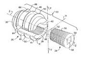
- FIG. 1is an exploded isometric view of a vertebral column stabilizing device forming a portion of a system constructed in accordance with one preferred embodiment of the invention
- FIG. 2is a reduced side elevational view of one tool of the system of this invention and which is arranged to insert an expandable insert forming a portion of the device shown in FIG. 1 ;
- FIG. 3is a reduced top elevational view of the tool shown in FIG. 2 ;
- FIG. 4is a reduced side elevational view of another tool of the system of this invention and which is arranged to insert an expansion insert, also forming a portion of the device of FIG. 1 , into the expandable insert of FIG. 1 ;
- FIG. 5is a greatly enlarged view taken along line 5 — 5 of FIG. 3 ;
- FIG. 6Ais a side elevational view of the expandable insert of FIG. 1 :
- FIG. 6Bis an end view taken along line 6 B— 6 B of FIG. 6A ;
- FIG. 6Cis an end view taken along line 6 C— 6 C of FIG. 6A ;
- FIG. 6Dis a top elevational view of the expandable insert of FIG. 6 A:
- FIG. 6Eis an end view taken along line 6 E— 6 E of FIG. 6D ;
- FIG. 6Fis an end view taken along line 6 F— 6 F of FIG. 6D ;
- FIG. 7Ais an enlarged side elevational view of the expansion insert of FIG. 1 :
- FIG. 7Bis an end view taken along line 7 B— 7 B of FIG. 7A ;
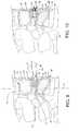
- FIG. 8is an illustration showing the expandable insert of FIG. 1 being inserted into the intervertebral space between a superior vertebra and an inferior vertebra using the deployment tool shown in FIGS. 2 and 4 ;
- FIG. 9is an illustration showing the expansion insert of FIG. 1 being inserted into the expandable insert once the expandable insert has been positioned in the intervertebral space between a superior vertebra and an inferior vertebra using the deployment tools shown in FIGS. 2 , 3 and 4 ;
- FIG. 10is an illustration showing the stabilizing device in place after it has been deployed in the intervertebral space between a superior vertebra and an inferior vertebra to stabilize those vertebrae;
- FIG. 11is an enlarged view taken along line 11 — 11 of FIG. 4 ;
- FIG. 12Ais a view similar to FIG. 6C but showing an alternative expandable insert constructed in accordance with this invention to facilitate visualization of the deployment of the insert;
- FIG. 12Bis a view similar to FIG. 6B but showing the alternative expandable insert constructed of FIG. 12 A.
- the system 20basically comprises a stabilization device 22 and a deployment system 24 for the device.
- the stabilization device 22is itself composed of two components, namely, a self-tapping expandable insert 26 and an expansion insert or screw 28 (see FIG. 1 ). The details of the insert 26 and expansion screw 28 will be described later. Suffice for now to say that the insert 26 is arranged to be screwed into the intervertebral space 12 between a superior vertebrae 14 A and an inferior vertebrae 14 B at the location to be stabilized as selected by the surgeon. Insert 26 is screwed into place by a first one of two tools making up the deployment system 24 .
- the first tool of the system 24i.e., the tool for screwing the insert into the intervertebral space 12 , is designated by the reference number 30 and includes a handle 32 and an elongated hollow shaft 32 .
- the distal free end of the tool 30is arranged for engaging the expandable insert 26 and driving (i.e., screwing) it into the intervertebral space 12 to the desired depth and so that the insert is at an appropriate orientation (as will be described later).
- the second tool of the systemi.e., the tool for screwing the expansion screw 28 into the insert 26
- This toolis arranged to be inserted into a passageway (to be described later) in the tool 30 and to be guided thereby to carry the threaded screw 28 into the expandable insert and to screw the threaded screw to a desired depth therein.
- the structural details of both tools 30 and 34will be described later.
- the expandable insert 26basically comprises a cylindrical member or body having a distal end 36 and a proximal end 38 .
- a threaded, cylindrical bore 40extends into the member from the proximal end 38 to a point close to the distal end 36 .
- the boreis centered about the central longitudinal axis of the insert.
- a pair of slots 42 and 44are cut into the sidewall of the insert at diametrically opposed locations at the proximal end of the insert and communicate with the threaded bore 40 .
- the slotsextend from the proximal end 38 to a point close to the distal end 36 and are coplanar and centered about the central longitudinal axis of the insert.
- a self-tapping helical thread 46extends about the periphery of the cylindrical outer surface 48 of the expandable member. The helical thread is interrupted at each slot. The helical thread tapers from its root, i.e., the cylindrical outer surface 48 to its apex 50 , to form a sharp, bone-cutting, self-tapping edge.
- the height (i.e., distance from the root 48 to the apex 50 ) of the self-tapping thread 46is selected so that it will readily cut into the hard, cortical bone 16 of the opposed vertebrae, but not into the softer, interior cancellous bone 18 .
- the expandable insert 26may be of any size consistent with the anatomy of the patient. Three particularly useful sizes are 8 mm, 9 mm and 10 mm, but such sizes are merely exemplary of any size insert which can be used. In any case, the outside diameter of the cylindrical portion 48 of the insert 26 is selected so that it will fit closely within the space between opposed vertebrae.
- the expansion screw 28basically comprises a somewhat truncated, conically shaped body having a distal end 52 and a proximal end 54 .
- the screwtapers linearly from its larger outside diameter proximal end to its smaller outside diameter distal end.
- a fine helical thread 56extends about the tapering outer surface of the screw. The threads are of the same size and pitch as those making up the threaded bore 40 in the expandable insert 26 .
- the outside diameter of the distal end 36 of the expansion screwis just slightly less than the inside diameter of the threaded bore 40 of the expandable insert to enable the distal end of the expansion screw to be introduced into the entrance to the bore and then screwed into the bore to whatever depth is desired to cause the expansion insert to spread apart, as will be described later.
- the proximal end 54 of the screwincludes a square slot 58 centered on the central longitudinal axis.
- the slot 58extends partially into the screw and is provided to receive a comparably shaped working end of the tool 34 to screw the screw 28 into the insert 26 .
- the device 22is arranged to be screwed into the intervertebral space from either the anterior or posterior (or even lateral ) side of the spinal column, depending upon the anatomic structures to be corrected and the wishes of the surgeon.
- the deviceis shown for insertion from the anterior aspect of the spinal column.
- the tool 30includes a hollow handle 60 from which the heretofore identified elongated hollow shaft 32 extends.
- the distal end 62 of the shaft 32terminates in a pair of opposed fingers or prongs 64 .
- the fingersare linear members extending parallel to the longitudinal axis of the tool and are sized so that each fits into a respective one of the slots 42 and 44 in the proximal end of the expandable insert 26 . This temporarily mounts the expandable insert 26 on the distal end of the tool 30 .
- the toolcan now be held by its handle 60 by the surgeon so that the distal end 36 of the insert 26 mounted thereon can be directed to face the intervertebral space 12 between the superior and inferior vertebrae, 14 A and 14 B, respectively.
- the handle 60 of the tool 30can then be twisted in the clockwise direction while pushing inward along the longitudinal axis of the tool to cause the self-tapping threads 46 on the insert 26 to begin to cut into the hard cortical bone 16 of those vertebrae.
- a pair of sharp starter notches 66are cut into the threads and contiguous distal end of the insert as shown in FIGS. 6A , 6 C, 6 D and 6 F.
- starter notchesenable the threads 46 to readily begin to cut into the cortical bone 16 when the distal end of the expandable insert 26 is screwed into the intervertebral space 12 by the rotary force imparted by the tool 30 .
- this screwserves to spread apart portions of the insert 26 .
- the portions of the insert body contiguous with the slots 42 and 44spread apart to spread the contiguous vertebrae.
- the threaded bore 40 in the expandable insert 26is cylindrical and the threaded screw 28 is tapered, e.g., tapers at a 4° angle from its proximal end 54 to its distal end 56 .
- the bore 40may be tapered and the screw 28 cylindrical.
- the amount of taper between the bore and the screwcan be selected to provide whatever amount of vertebral spreading is desired for any given amount of insertion of the screw within the bore.
- the screwing of the screw 28 into the threaded bore 40 of the insert 26is best accomplished by first loading the screw 28 into the tool 30 .
- the tool 30includes the hollow shaft 32 and contiguous hollow handle 60 .
- a central passageway 68extends down the shaft and through the handle.
- the inner diameter of the passageway 68is just slightly greater than the outside diameter of the widest portion of the screw 26 , i.e., its proximal end 54 .
- the screw 28can be inserted in the passageway 68 so that its longitudinal central axis is coaxial with the central axis of the tool 30 and with the longitudinal central axis of the expandable insert 26 .
- the screw 28may be introduced into the central passageway 68 of the tool 30 through either a side port or window 70 cut into the wall of the shaft adjacent the distal end 62 from which the pair of fingers 64 project.
- the screw 28can be preloaded in the passageway 68 .
- the screwis oriented so that its smaller diameter distal end is directed toward the free end 60 of the tool 30 .
- the proximal end 54 of the screw 28includes a square slot 58 therein to receive the working end of the tool 34 .
- the slot in this embodimentis shown as being square, it may be of any shape to accommodate the working end of the tool 34 .
- the slot 58tapers slightly, e.g., approximately 1° from the proximal end of the slot to its bottom.
- Other types of slotssuch as a Phillips head slot, a straight slot, a Torx head slot, etc., can be provided in the proximal end of the screw 28 to be engaged by a like shaped working end of the tool 34 .
- the tool 34like the tool 30 , includes an elongated handle 72 and an elongated shaft 74 projecting from the handle. The distal end of the shaft 24 tapers downward at 76 to a square tip working end 78 .
- the outside diameter of the shaft 74 of the tool 34is slightly less than the inside diameter of the passageway 68 in the tool 30 since the shaft is arranged to be extended through that passageway while the tool 30 holds the expandable insert 26 at the desired orientation (i.e., the slots 42 and 44 being in a plane generally perpendicular to the portion of the midline or longitudinal axis “Y” of the spinal column between the superior and inferior vertebrae).
- the tool 34can then be slid further inward through the passageway 68 until its square head 78 is received within the square slot 58 in the proximal end of the screw 28 located within the passageway 68 at the distal end thereof.
- Pushing inward on the screwdriver tool 34 while rotating it in the clockwise directionthus causes the screw 28 to enter into the threaded bore 40 in the insert 26 .
- Continued rotation and inward pushingwill drive the screw to the desired depth within the insert 26 .
- the handle of the tool 30is held stationary to ensure that the threaded insert 26 remains stationary (i.e., is not rotated) in its desired orientation. This feature is of considerable importance to maintain the slots 42 and 44 in the plane perpendicular to the midline axis Y of the patient's spine.
- the insert 26is oriented so that not only are the plane of its slots disposed perpendicularly to the midline axis Y, but also its longitudinal axis is coincident with the “Z” axis (an axis which as shown in FIGS.
- the insert 36can be oriented so that its longitudinal central axis extends at some angle other than perpendicular to the transverse or “X” axis of the spinal column shown in FIG. 1 , so long as the slots 42 and 44 are in a plane perpendicular to the midline (Y) axis of the spine. This feature gives the surgeon considerable leeway for the angle of the insertion approach to be taken, based on the patient's particular vertebral anatomy.
- the deployment of the stabilization device 22 of this inventiondoes not require the excision or resection of either the anterior or posterior ligaments.
- all the surgeon has to do to deploy the device 22 from the anterior aspect, such as shown in the drawings,is to merely temporarily displace the anterior ligament to the side.
- a small, longitudinally extending incisionmay be made in the ligament as an access way to the disk. This small incision should not compromise the strength of the ligament so long as it is made parallel to the longitudinal axis of the ligament.
- a small incisionis then made into the annulus of the disk. The nucleus or a portion of the nucleus is then removed to relieve pressure on the nerve root. The annulus is left essentially intact.
- the device 22can be deployed into the intervertebral space 12 , such as described above. Once the device is properly deployed, the tools of the deployment system 24 can be removed, allowing the anterior ligament to assume its normal position. The tensioning of the anterior ligament, which results from the spreading of the adjacent vertebrae 14 A and 14 B, has the effect of stabilizing the spine.
- the expandable insert 26 and the screw 28are each formed of wrought Titanium 6A 1-4V ELI alloy.
- this materialis merely exemplary of various other kinds of strong, biocompatible materials which may be utilized in the subject invention.
- the expandable insertcan be made in various sizes.
- the screwcan have an outer diameter, i.e., the diameter of the exterior self-tapping threads, of 8, 9 or 10 mm.
- the length of the insertcan also be of any desired size, e.g., 10 mm.
- the thickness or width of the slotsis approximately 1.9 mm and the length of the slots is approximately 8.5 mm for those exemplary inserts.
- the root 48 of the external threads 46i.e., the outside diameter of the cylindrical body, is approximately 6 mm for the 8 mm size insert, 7 mm for the 9 mm size insert, and 8 mm for the 10 mm size insert. All of the inserts have the same self-tapping thread 46 pitch, namely, 2.75 mm.
- the threaded cylindrical boreis of the insert 26 of M-4 size.
- the expansion screw 28is approximately 4.5 mm long.
- the square slot 58 in the proximal end of the screw 28is approximately 1.4 mm and extends approximately 3.4 mm deep into the screw.
- the tool 30has an elongated shaft of approximately 4.291 inches and an outside diameter of approximately 0.32 inch.
- the handleis approximately 3.5 inches long and 0.75 inches in diameter.
- the fingers 64 at the distal end of the insert driver 30are approximately 0.3 inches long, approximately 0.09 inches wide and taper downward approximately 1° toward their free end.
- the width of the arch over the window 70 at the distal end of the expandable insert driveris approximately 0.1 inches wide.
- the tool 34has an elongated shaft of approximately 7.625 inches with an outside diameter of 0.24 inches.
- the handleis approximately 3.5 inches long and approximately 0.75 inches in diameter.
- the shafttapers downward to a square cross-sectional area of 1.4 mm to fit within the square slot 58 in the proximal end of the screw 28 .
- the free distal end 78 of the screwdriver 34is approximately 0.2 inches long and tapers at an angle of 1° to its terminus.
- the expandable insert 26 of this inventionmay be provided with a small opening or access port in the distal end of the expandable insert 26 .
- This alternative embodiment of the expandable insertis shown in FIG. 12 and is identical in construction to the embodiment of the expandable insert described heretofore, except for the inclusion of a small access opening or port 82 .
- the port 82is centered on the longitudinal axis Z and in communication with the bore 40 of the insert.
- This opening or portcan also be used to facilitate endoscopic placement of the insert 26 after removal of the nucleus of the disk.
- the access opening or portshould be of a sufficient size to permit the passage of an endoscope therethrough without compromising the strength or integrity of the device.
- an expandable insertwith such an access opening or port is a follows.
- an endoscope(not shown), either rigid or flexible, with a diameter smaller than the inside diameter of the passageway 68 in the tool and smaller than the diameter of the access port, can inserted through the passageway and through the access port in the expandable insert. This action will permit visualization of the placement of the expandable insert into the intervertebral space so that it is at the desired depth and orientation. Rotation of the tool 30 can be readily accomplished to achieve that end while the endoscope enables the surgeon to visually monitor the deployment of the expandable insert to ensure that placement of that insert avoids contact with any sensitive structures, e.g., the nerve root.
- a working channel in the endoscopecould be used to effectuate irrigation and aspiration, as well as providing an access portal for the introduction of small instruments, e.g., instruments used to remove any vestiges of the nucleus which may still impinge on the nerve root.
- an access port 82 in the expandable insert 26enables future entry and nerve decompression, without removal of the insert. To achieve that end all that is required is to gain access to the proximal end of the in-place expansion screw 28 , either surgically or endoscopically. Once that has been achieved the expansion screw may be screwed out of the bore in the insert 26 by any suitable tool, e.g., the tool 34 . After the expansion screw 28 has been removed the intervertebral space may be inspected and revised (if necessary), by use of an endoscope inserted through the bore 40 and communicating access port 82 in the insert 26 .
- the stabilizing device of the subject systemmakes use of a simple expandable cylindrical member including a self-tapping thread on its outside surface and a simple expansion screw.
- the devicecan be placed into the intervertebral space without requiring any bone boring.
- the height of the self-tapping thread on the expandable memberis selected so that it cuts into the cortical bone, but not substantially into the cancellous bone. This feature makes it particularly suitable for use on children, since it should not impede bone growth.
- the expansion screwcan be screwed as deeply as desired into the threaded bore enables the user to easily control and adjust the degree of expansion of the expandable member, and hence vertebral spacing.
- the co-acting tools making up the deployment systemare particularly suited for deploying the expandable insert to the desired depth and orientation.
- one of the toolsalso includes a passageway for the other tool to extend therethrough to screw the threaded screw into the threaded bore to the desired depth while the first tool holds the expandable insert in the desired orientation. Once the screw is at the desired position, thereby effecting the desired amount of spreading of the expandable insert, both tools may be removed, leaving the device 22 in position stabilizing the spine.
- the devicebeing adjustable, enables varying amounts of equalization of the height of the vertebral bodies to be tailored to the specific needs of each patient. All of this is accomplished at any portion of the vertebral column without occupying space outside the spinal column, which action could result in pain or traumatic injury to adjacent anatomic structures.
- the deviceOnce in place the device is very stable and resistant to displacement notwithstanding movement or traction forces exerted physiologically by the patient.
- the small diameter of the device 22 and the tools for deploying itrender the system of this invention particularly suitable for use in minimally invasive surgical techniques.
- the system of the subject inventioncan be deployed through a relatively small, e.g., 14 French, introducer tube like that typically used for various types of minimally invasive surgical procedures.
- the device and its deployment systemcan be used in conventional cut-down surgical procedures.
- the subject systemenables the stabilization of the spine, the re-establishment of physiological distance between vertebral bodies and the re-establishment of normal lordotic curve of the spinal column, without requiring fusion of the two vertebrae to each other either by means of an implant into which bone material is either applied or grows, or a device which mechanically fixes the two vertebrae to each other via plates, bars, rods, etc.
Landscapes
- Health & Medical Sciences (AREA)
- Orthopedic Medicine & Surgery (AREA)
- Engineering & Computer Science (AREA)
- Biomedical Technology (AREA)
- Neurology (AREA)
- Life Sciences & Earth Sciences (AREA)
- Transplantation (AREA)
- General Health & Medical Sciences (AREA)
- Veterinary Medicine (AREA)
- Heart & Thoracic Surgery (AREA)
- Public Health (AREA)
- Animal Behavior & Ethology (AREA)
- Vascular Medicine (AREA)
- Cardiology (AREA)
- Oral & Maxillofacial Surgery (AREA)
- Physical Education & Sports Medicine (AREA)
- Surgery (AREA)
- Molecular Biology (AREA)
- Medical Informatics (AREA)
- Nuclear Medicine, Radiotherapy & Molecular Imaging (AREA)
- Prostheses (AREA)
- Surgical Instruments (AREA)
Abstract
Description
This is a Divisional application of application Ser. No. 09/348,612, filed on Jul. 6, 1999, now U.S. Pat. No. 6,436,142 entitled System for Stabilizing the Vertebral Column Including Deployment Instruments and Variable Expansion Inserts Therefor.
This invention relates generally to medical devices and more specifically to intervertebral disk stabilization systems and methods of stabilizing the spine of living beings.
This application claims priority on Brazilian Patent Application, Serial Number 9805340-0, filed on Dec. 14, 1998, entitled VARIABLE EXPANSION INSERT FOR STABILIZING THE VERTEBRAL COLUMN, whose disclosure is incorporated by reference herein.
Numerous types of devices or systems are available for the fixation of the vertebral column of living beings. For example, some devices are prostheses, e.g., plates or other structures, formed of rigid materials of fixed sizes and volumes capable of being fastened, e.g., bolted, to the bony structure of vertebral column anteriorly and/or posteriorly through bores excavated in those vertebrae involved. The fasteners used in such devices or systems are commonly referred to as cortical bolts or medullary bolts, depending upon the type of thread of the bolt. In some systems or devices parts of human bone from the patient himself/herself, or from bone banks or dehydrated human bone is used to aid in securing the prosthesis to the bony structure(s) of the vertebrae. One of the greatest drawbacks of such prior art devices or systems are that they are difficult to use. In this regard, the deployment and mounting of a bolt-based fixation device is delayed by the necessity to bore the bony structures of the vertebrae for receipt of the securement bolts. Moreover, the location of the bore holes for those bolts must be precisely located and oriented to match up with the pre-established holes in the plates or other support structures forming the remainder of the device or system. Another drawback of such spine fixation devices is the fact that they typically take up such substantial space in the body when secured in place, that they may result in the formation of traumatic lesions to adjacent anatomic structures. Lastly, traction exerted by movement of the patient, may cause partial or total detachment of one or more of the bone fixation bolts, which action may also result in the formation of traumatic lesions to adjacent anatomic structures and/or instability of part or all of the fixation system.
Various patents and printed patent literature have also disclosed devices and systems for fixation or stabilization of the spine or vertebral column of a living being. See for example, U.S. Pat. No.: 4,863,476 (Shepperd), U.S. Pat. No. 5,591,235 (EKuslich), U.S. Pat. No. 5,653,761 (Pisharodi), U.S. Pat. No. 5,653,762 (Pisharodi), U.S. Pat. No. 5,653,763 (Errico et al.), U.S. Pat. No. 5,693,100 (Pisharodi), U.S. Pat. No. 5,713,904 (Errico et al.), U.S. Pat. No. 5,782,832 (Larsen et al.), U.S. Pat. No. 5,865,847 (Kohrs et al.) and U.S. Pat. No. 5,865,848 (Baker), PCT Application Publication Nos.: WO 90/00037, WO 95/31158, WO 97/06753, and WO 98/10722, European Patent Application Nos.: 0 599 766 A1, and 0 635 246 A1, Spanish Patent No. ES 2 099 008, and Russian Patent No.: 2063730.
While the spine stabilization or fixation devices of the patent literature may be generally suitable for their intended purposes, they still leave much to be desired from the standpoints of ease of use and effectiveness. For example, some prior art spine fixation devices require excision of the anterior and/or posterior ligaments, thereby destabilizing the spine. Thus, these systems require some mechanical means to fuse or fix the adjacent vertebrae to each other, e.g., removal or drilling of the bone to secure the device in position with respect to each vertebra with some type of mechanical bridge therebetween. Other types of fixation devices make use of hollow or apertured implants designed to be packed with bone chips or particles and placed into excavations through the exterior, hard cortical bone, into the soft interior cancellous bone of opposed vertebrae to facilitate the ingrowth of bone into the implant and thus fuse the two vertebrae together. This type of fixation device may be prone to damage the immediately adjacent vertebrae due to compressive forces thereon.
While some prior art devices don't require excision of the ligaments to effect spine stabilization, they, nevertheless, typically require the partial or complete extraction and removal of the disk in order to place them into the intervertebral space, where such devices seek to replace the function of the disk (albeit less than optimally).
Notwithstanding all of the prior art now in existence, a need still exists for a spine stabilization system which is easy to use, effective, and safe.
It is a general object of this invention to provide a vertebral-column stabilizing device and deployment system which overcomes the disadvantages of the prior art and addresses those needs.
It is another object of this invention to provide a device and system for deploying it in the intervertebral space between a superior and inferior vertebra of a living being to stabilize the spine.
It is another object of this invention to provide a device for deployment in the intervertebral space between a superior and inferior vertebra of a living being to stabilize the spine, yet which does not require the excision of either the anterior or posterior ligament.
It is another object of this invention to provide a device and system for deploying it to stabilize the spine of a living being without requiring removal of bone.
It is another object of this invention to provide a device and system for deploying it to stabilize the spine of a living being without interruption or removal of bone growth surfaces.
It is another object of this invention to provide a device for deployment in the intervertebral space between a superior and inferior vertebra of a living being to stabilize the spine, yet which does not require the complete removal of the interposed disk, e.g., all it requires is the creation of a small opening in the disk through which the nucleus is excised.
It is another object of this invention to provide a device and system for deploying it in the intervertebral space between a superior and inferior vertebra of a living being, so that when the device is deployed it effectively stabilizes the spine.
It is another object of this invention to provide an adjustable and controllable spine stabilization device and system for deploying it in the intervertebral space between adjacent vertebra to establish a desired lordotic curvature of the spine.
It is another object of this invention to provide a spine stabilization device and system for deploying it in the intervertebral space between a superior and inferior vertebra which is easy to use.
It is another object of this invention to provide an expandable vertebral-column stabilizing device which is simple in construction.
It is another object of this invention to provide a deployment system which is simple in construction and easy to use to deploy an expandable vertebral-column stabilizing device.
A system for stabilizing the vertebral column of a living being. The system includes a variable expansion device an a deployment system for deploying the device. When deployed the device stabilizes a superior vertebra and immediately adjacent inferior vertebra of the vertebral column, without requiring the excision of bone from the superior or inferior vertebrae or the resection of the adjacent longitudinal proximal or distal ligaments.
The stabilizing device basically comprises an expandable insert and an expansion insert. The expandable insert comprises a hollow cylindrical body having a longitudinal axis, an proximal end portion and a distal end portion. The proximal end portion has a pair of slots extending therethrough generally parallel to the longitudinal axis of the expandable insert. The slots extend partially into the distal end portion of the expandable insert. The distal end portion and at least a portion of the proximal end portion of the expandable insert have an outer surface about which an external, helical, self-tapping thread extends. The distal end portion and the at least a portion of the proximal end portion of the expandable insert are of a sufficient size to be screwed into the intervertebral space between the superior and inferior vertebrae, to an operative position and orientation. In the operative position and orientation the expandable insert is located at a desired depth within the intervertebral space and its slots are oriented in a plane generally perpendicular to the portion of the longitudinal axis of the being's vertebral column between the superior and inferior vertebrae.
The self-tapping thread of the expandable insert is a sufficient height to cut into the cortical bone of the superior and inferior vertebrae contiguous to the intervertebral space, but not substantially into the cancellous bone.
The proximal end portion of the expandable insert has an internally threaded, e.g., fine threaded, bore extending through it and into and through at least a portion of the distal end portion of the expandable insert. The internally threaded bore communicates with the slots in the expandable insert.
The expansion insert has an externally threaded outer surface and is arranged to be screwed into the internally threaded bore in the proximal end portion of the expandable insert when the expandable insert is in the desired position and orientation. In a preferred embodiment the outer surface of the expansion insert is tapered from the proximal end to the distal end. Thus, when the expansion insert is screwed into the threaded bore in the expandable insert, it causes the slots to open and thereby spread the superior and inferior vertebrae apart, thereby stabilizing the being's vertebral column.
The deployment system in the preferred embodiment comprises two tools which are arranged to cooperate with each other. A first one of the tools has portion, e.g., an elongated hollow shaft having a pair of extending fingers, adapted to fit into at least one of the slots in the expansion insert to enable the tool to screw the expandable insert to the desired depth and orientation in the intervertebral space between the superior and inferior vertebrae and to hold it in the desired orientation at that depth. The second tool, e.g., an elongated rod-like shaft arranged to extend through the hollow interior of the first tool, has a working end, e.g., a square head, adapted to engage a portion, e.g., a square slot, of the expansion insert to screw the expansion into the threaded bore in the proximal end portion of the expandable insert to cause the slots to spread apart, whereupon the device stabilizes the being's vertebral column.
Referring now to the various figures of the drawing wherein like reference characters refer to like parts, there is shown generally at20 inFIG. 9 a system for stabilizing thespinal column 10 of a living being. The system20 basically comprises astabilization device 22 and adeployment system 24 for the device. Thestabilization device 22 is itself composed of two components, namely, a self-tappingexpandable insert 26 and an expansion insert or screw28 (see FIG.1). The details of theinsert 26 andexpansion screw 28 will be described later. Suffice for now to say that theinsert 26 is arranged to be screwed into theintervertebral space 12 between asuperior vertebrae 14A and aninferior vertebrae 14B at the location to be stabilized as selected by the surgeon.Insert 26 is screwed into place by a first one of two tools making up thedeployment system 24.
Once theinsert 26 is in place, theexpansion screw 28 is screwed into theinsert 26 by the second tool of thedeployment system 24. This action causes portions of theinsert 26 to spread apart, whereupon the confronting portions of the inferior and superior vertebrae are concomitantly spread apart to stabilize the spinal column. The first tool of thesystem 24, i.e., the tool for screwing the insert into theintervertebral space 12, is designated by thereference number 30 and includes ahandle 32 and an elongatedhollow shaft 32. The distal free end of thetool 30 is arranged for engaging theexpandable insert 26 and driving (i.e., screwing) it into theintervertebral space 12 to the desired depth and so that the insert is at an appropriate orientation (as will be described later). The second tool of the system, i.e., the tool for screwing theexpansion screw 28 into theinsert 26, is designated by thereference number 34. This tool is arranged to be inserted into a passageway (to be described later) in thetool 30 and to be guided thereby to carry the threadedscrew 28 into the expandable insert and to screw the threaded screw to a desired depth therein. The structural details of bothtools
Referring now toFIG. 1 , the details of the construction of the stabilizingdevice 22 will now be discussed. Thus, as can be seen, theexpandable insert 26 basically comprises a cylindrical member or body having adistal end 36 and aproximal end 38. A threaded,cylindrical bore 40 extends into the member from theproximal end 38 to a point close to thedistal end 36. The bore is centered about the central longitudinal axis of the insert. A pair ofslots proximal end 38 to a point close to thedistal end 36 and are coplanar and centered about the central longitudinal axis of the insert. A self-tappinghelical thread 46 extends about the periphery of the cylindricalouter surface 48 of the expandable member. The helical thread is interrupted at each slot. The helical thread tapers from its root, i.e., the cylindricalouter surface 48 to itsapex 50, to form a sharp, bone-cutting, self-tapping edge. As will be discussed later, the height (i.e., distance from theroot 48 to the apex50) of the self-tappingthread 46 is selected so that it will readily cut into the hard,cortical bone 16 of the opposed vertebrae, but not into the softer, interiorcancellous bone 18.
Theexpandable insert 26 may be of any size consistent with the anatomy of the patient. Three particularly useful sizes are 8 mm, 9 mm and 10 mm, but such sizes are merely exemplary of any size insert which can be used. In any case, the outside diameter of thecylindrical portion 48 of theinsert 26 is selected so that it will fit closely within the space between opposed vertebrae.
Theexpansion screw 28 basically comprises a somewhat truncated, conically shaped body having adistal end 52 and aproximal end 54. The screw tapers linearly from its larger outside diameter proximal end to its smaller outside diameter distal end. A finehelical thread 56 extends about the tapering outer surface of the screw. The threads are of the same size and pitch as those making up the threaded bore40 in theexpandable insert 26. The outside diameter of thedistal end 36 of the expansion screw is just slightly less than the inside diameter of the threaded bore40 of the expandable insert to enable the distal end of the expansion screw to be introduced into the entrance to the bore and then screwed into the bore to whatever depth is desired to cause the expansion insert to spread apart, as will be described later. Theproximal end 54 of the screw includes asquare slot 58 centered on the central longitudinal axis. Theslot 58 extends partially into the screw and is provided to receive a comparably shaped working end of thetool 34 to screw thescrew 28 into theinsert 26.
It should be pointed out at this juncture that thedevice 22 is arranged to be screwed into the intervertebral space from either the anterior or posterior (or even lateral ) side of the spinal column, depending upon the anatomic structures to be corrected and the wishes of the surgeon. For example, for use of the system of this invention with the cervical spine it is expected that an anterior approach to that portion of the spine will be preferred, while use of the system in the lumbar spine will likely be from the posterior, although either approach (or even a lateral approach) may be accomplished in either portion of the spine. In the exemplary embodiment shown herein, the device is shown for insertion from the anterior aspect of the spinal column.
Referring now toFIGS. 2 ,4 and8, the details of thedeployment tool 30 will now be described. Thus, it can be seen that thetool 30 includes ahollow handle 60 from which the heretofore identified elongatedhollow shaft 32 extends. Thedistal end 62 of theshaft 32 terminates in a pair of opposed fingers or prongs64. The fingers are linear members extending parallel to the longitudinal axis of the tool and are sized so that each fits into a respective one of theslots expandable insert 26. This temporarily mounts theexpandable insert 26 on the distal end of thetool 30. The tool can now be held by itshandle 60 by the surgeon so that thedistal end 36 of theinsert 26 mounted thereon can be directed to face theintervertebral space 12 between the superior and inferior vertebrae,14A and14B, respectively. Thehandle 60 of thetool 30 can then be twisted in the clockwise direction while pushing inward along the longitudinal axis of the tool to cause the self-tappingthreads 46 on theinsert 26 to begin to cut into the hardcortical bone 16 of those vertebrae. In order to expedite the cutting action into the hard, cortical bone, a pair ofsharp starter notches 66 are cut into the threads and contiguous distal end of the insert as shown inFIGS. 6A ,6C,6D and6F. These starter notches enable thethreads 46 to readily begin to cut into thecortical bone 16 when the distal end of theexpandable insert 26 is screwed into theintervertebral space 12 by the rotary force imparted by thetool 30. Continued rotation of thetool 30 about its longitudinal axis while applying inward pressure drives, i.e., screws, theinsert 26 deeper into theintervertebral space 12.
When the insert is at the desired position, such as shown inFIG. 8 , itsslots FIGS. 1 and 8 ) of the spine extending through theadjacent vertebrae lines 80 are provided on the end of the handle of thetool 30 for viewing by the surgeon.
With the threadedinsert 26 in the desired position and orientation, such as shown inFIG. 8 , it is now ready to receive the threadedscrew 28. As mentioned earlier, this screw serves to spread apart portions of theinsert 26. In particular, when thescrew 28 is screwed into the threaded bore40 of theinsert 26, the portions of the insert body contiguous with theslots
In accordance with the preferred embodiment of the invention shown herein, the threaded bore40 in theexpandable insert 26 is cylindrical and the threadedscrew 28 is tapered, e.g., tapers at a 4° angle from itsproximal end 54 to itsdistal end 56. As should be appreciated by those skilled in the art, alternatively, thebore 40 may be tapered and thescrew 28 cylindrical. Moreover, the amount of taper between the bore and the screw can be selected to provide whatever amount of vertebral spreading is desired for any given amount of insertion of the screw within the bore. Thus, when the screw is screwed into the bore the mating flaring (tapering) and cylindrical surface threads engage each other to spread apart the portions of the expandable insert contiguous with theslots
The screwing of thescrew 28 into the threaded bore40 of theinsert 26 is best accomplished by first loading thescrew 28 into thetool 30. To that end, as noted earlier, thetool 30 includes thehollow shaft 32 and contiguoushollow handle 60. Acentral passageway 68 extends down the shaft and through the handle. The inner diameter of thepassageway 68 is just slightly greater than the outside diameter of the widest portion of thescrew 26, i.e., itsproximal end 54. Thus, thescrew 28 can be inserted in thepassageway 68 so that its longitudinal central axis is coaxial with the central axis of thetool 30 and with the longitudinal central axis of theexpandable insert 26. Thescrew 28 may be introduced into thecentral passageway 68 of thetool 30 through either a side port orwindow 70 cut into the wall of the shaft adjacent thedistal end 62 from which the pair offingers 64 project. Alternatively, thescrew 28 can be preloaded in thepassageway 68. In either case, the screw is oriented so that its smaller diameter distal end is directed toward thefree end 60 of thetool 30.
As mentioned earlier, and as shown best inFIGS. 7A and 7B , theproximal end 54 of thescrew 28 includes asquare slot 58 therein to receive the working end of thetool 34. While the slot in this embodiment is shown as being square, it may be of any shape to accommodate the working end of thetool 34. In a preferred embodiment of the invention, theslot 58 tapers slightly, e.g., approximately 1° from the proximal end of the slot to its bottom. Other types of slots, such as a Phillips head slot, a straight slot, a Torx head slot, etc., can be provided in the proximal end of thescrew 28 to be engaged by a like shaped working end of thetool 34. Thetool 34, like thetool 30, includes anelongated handle 72 and anelongated shaft 74 projecting from the handle. The distal end of theshaft 24 tapers downward at76 to a squaretip working end 78.
The outside diameter of theshaft 74 of thetool 34 is slightly less than the inside diameter of thepassageway 68 in thetool 30 since the shaft is arranged to be extended through that passageway while thetool 30 holds theexpandable insert 26 at the desired orientation (i.e., theslots tool 34 can then be slid further inward through thepassageway 68 until itssquare head 78 is received within thesquare slot 58 in the proximal end of thescrew 28 located within thepassageway 68 at the distal end thereof.
Pushing inward on thescrewdriver tool 34 while rotating it in the clockwise direction thus causes thescrew 28 to enter into the threaded bore40 in theinsert 26. Continued rotation and inward pushing will drive the screw to the desired depth within theinsert 26. All the while that thetool 34 is used to rotate thescrew 28, the handle of thetool 30 is held stationary to ensure that the threadedinsert 26 remains stationary (i.e., is not rotated) in its desired orientation. This feature is of considerable importance to maintain theslots insert 26 were able to rotate so that itsslots device 22 would effect a skewing of the adjacent vertebrae. Instead, by holding the slots so that they are in a plane perpendicular to the longitudinal axis of the spine, the system is able to provide desired vertebral spreading without skewing. In the embodiment shown, theinsert 26 is oriented so that not only are the plane of its slots disposed perpendicularly to the midline axis Y, but also its longitudinal axis is coincident with the “Z” axis (an axis which as shown inFIGS. 1 and 8 extends anteriorly-posteriorly and perpendicular to the Y axis). However, this is not the only orientation that the stabilizingdevice 22 of this invention may be used. In particular, theinsert 36 can be oriented so that its longitudinal central axis extends at some angle other than perpendicular to the transverse or “X” axis of the spinal column shown inFIG. 1 , so long as theslots
As noted earlier, the deployment of thestabilization device 22 of this invention does not require the excision or resection of either the anterior or posterior ligaments. For example, all the surgeon has to do to deploy thedevice 22 from the anterior aspect, such as shown in the drawings, is to merely temporarily displace the anterior ligament to the side. If necessary a small, longitudinally extending incision may be made in the ligament as an access way to the disk. This small incision should not compromise the strength of the ligament so long as it is made parallel to the longitudinal axis of the ligament. In any even, a small incision is then made into the annulus of the disk. The nucleus or a portion of the nucleus is then removed to relieve pressure on the nerve root. The annulus is left essentially intact. This provides additional support and cushioning for the vertebrae. Once the nucleus has has been removed, thedevice 22 can be deployed into theintervertebral space 12, such as described above. Once the device is properly deployed, the tools of thedeployment system 24 can be removed, allowing the anterior ligament to assume its normal position. The tensioning of the anterior ligament, which results from the spreading of theadjacent vertebrae
In accordance with the proposed commercial embodiments of this invention, theexpandable insert 26 and thescrew 28 are each formed of wrought Titanium 6A 1-4V ELI alloy. However, this material is merely exemplary of various other kinds of strong, biocompatible materials which may be utilized in the subject invention. As mentioned earlier, the expandable insert can be made in various sizes. For example, the screw can have an outer diameter, i.e., the diameter of the exterior self-tapping threads, of 8, 9 or 10 mm. The length of the insert can also be of any desired size, e.g., 10 mm. The thickness or width of the slots is approximately 1.9 mm and the length of the slots is approximately 8.5 mm for those exemplary inserts. Theroot 48 of theexternal threads 46, i.e., the outside diameter of the cylindrical body, is approximately 6 mm for the 8 mm size insert, 7 mm for the 9 mm size insert, and 8 mm for the 10 mm size insert. All of the inserts have the same self-tappingthread 46 pitch, namely, 2.75 mm. The threaded cylindrical bore is of theinsert 26 of M-4 size. Theexpansion screw 28 is approximately 4.5 mm long. Thesquare slot 58 in the proximal end of thescrew 28 is approximately 1.4 mm and extends approximately 3.4 mm deep into the screw.
Thetool 30 has an elongated shaft of approximately 4.291 inches and an outside diameter of approximately 0.32 inch. The handle is approximately 3.5 inches long and 0.75 inches in diameter. Thefingers 64 at the distal end of theinsert driver 30 are approximately 0.3 inches long, approximately 0.09 inches wide and taper downward approximately 1° toward their free end. The width of the arch over thewindow 70 at the distal end of the expandable insert driver is approximately 0.1 inches wide.
Thetool 34 has an elongated shaft of approximately 7.625 inches with an outside diameter of 0.24 inches. The handle is approximately 3.5 inches long and approximately 0.75 inches in diameter. The shaft tapers downward to a square cross-sectional area of 1.4 mm to fit within thesquare slot 58 in the proximal end of thescrew 28. The freedistal end 78 of thescrewdriver 34 is approximately 0.2 inches long and tapers at an angle of 1° to its terminus.
In order to facilitate visualization and access to the intervertebral space theexpandable insert 26 of this invention may be provided with a small opening or access port in the distal end of theexpandable insert 26. This alternative embodiment of the expandable insert is shown in FIG.12 and is identical in construction to the embodiment of the expandable insert described heretofore, except for the inclusion of a small access opening orport 82. As can be seen theport 82 is centered on the longitudinal axis Z and in communication with thebore 40 of the insert. This opening or port can also be used to facilitate endoscopic placement of theinsert 26 after removal of the nucleus of the disk. The access opening or port should be of a sufficient size to permit the passage of an endoscope therethrough without compromising the strength or integrity of the device. Use of an expandable insert with such an access opening or port is a follows. Once theexpandable insert 26 is mounted on thetool 30, an endoscope (not shown), either rigid or flexible, with a diameter smaller than the inside diameter of thepassageway 68 in the tool and smaller than the diameter of the access port, can inserted through the passageway and through the access port in the expandable insert. This action will permit visualization of the placement of the expandable insert into the intervertebral space so that it is at the desired depth and orientation. Rotation of thetool 30 can be readily accomplished to achieve that end while the endoscope enables the surgeon to visually monitor the deployment of the expandable insert to ensure that placement of that insert avoids contact with any sensitive structures, e.g., the nerve root. A working channel in the endoscope could be used to effectuate irrigation and aspiration, as well as providing an access portal for the introduction of small instruments, e.g., instruments used to remove any vestiges of the nucleus which may still impinge on the nerve root.
The use of anaccess port 82 in theexpandable insert 26 enables future entry and nerve decompression, without removal of the insert. To achieve that end all that is required is to gain access to the proximal end of the in-place expansion screw 28, either surgically or endoscopically. Once that has been achieved the expansion screw may be screwed out of the bore in theinsert 26 by any suitable tool, e.g., thetool 34. After theexpansion screw 28 has been removed the intervertebral space may be inspected and revised (if necessary), by use of an endoscope inserted through thebore 40 and communicatingaccess port 82 in theinsert 26.
As should be appreciated from the foregoing, the stabilizing device of the subject system makes use of a simple expandable cylindrical member including a self-tapping thread on its outside surface and a simple expansion screw. The device can be placed into the intervertebral space without requiring any bone boring. Moreover, the height of the self-tapping thread on the expandable member is selected so that it cuts into the cortical bone, but not substantially into the cancellous bone. This feature makes it particularly suitable for use on children, since it should not impede bone growth. Moreover, by virtue of the fact that the expansion screw can be screwed as deeply as desired into the threaded bore enables the user to easily control and adjust the degree of expansion of the expandable member, and hence vertebral spacing.
The co-acting tools making up the deployment system are particularly suited for deploying the expandable insert to the desired depth and orientation. To that end, one of the tools also includes a passageway for the other tool to extend therethrough to screw the threaded screw into the threaded bore to the desired depth while the first tool holds the expandable insert in the desired orientation. Once the screw is at the desired position, thereby effecting the desired amount of spreading of the expandable insert, both tools may be removed, leaving thedevice 22 in position stabilizing the spine.
Among the salient features and advantages of the subject invention are a reduction of the time for spinal surgery due to the ease of use and the absence of the need for prior bone boring. Moreover, the device, being adjustable, enables varying amounts of equalization of the height of the vertebral bodies to be tailored to the specific needs of each patient. All of this is accomplished at any portion of the vertebral column without occupying space outside the spinal column, which action could result in pain or traumatic injury to adjacent anatomic structures. Once in place the device is very stable and resistant to displacement notwithstanding movement or traction forces exerted physiologically by the patient. The small diameter of thedevice 22 and the tools for deploying it render the system of this invention particularly suitable for use in minimally invasive surgical techniques. Thus, the system of the subject invention can be deployed through a relatively small, e.g., 14 French, introducer tube like that typically used for various types of minimally invasive surgical procedures. Alternatively, the device and its deployment system can be used in conventional cut-down surgical procedures. In any case, the subject system enables the stabilization of the spine, the re-establishment of physiological distance between vertebral bodies and the re-establishment of normal lordotic curve of the spinal column, without requiring fusion of the two vertebrae to each other either by means of an implant into which bone material is either applied or grows, or a device which mechanically fixes the two vertebrae to each other via plates, bars, rods, etc.
Without further elaboration the foregoing will so fully illustrate my invention that others may, by applying current or future knowledge, adopt the same for use under various conditions of service.
Claims (8)
1. A system for stabilizing a superior vertebra and immediately adjacent inferior vertebra of the vertebral column of a living being without requiring the excision of bone from the superior or inferior vertebrae or the resection of the adjacent longitudinal proximal or distal ligaments, said system comprising a variable expansion device and a deployment system, said variable expansion device comprising a hollow one-piece expandable insert and an expansion insert, said expandable insert comprising a one-piece cylindrical body having a longitudinal axis and a proximal end portion and a distal end portion, said proximal end portion having a pair of slots extending therethrough generally parallel to the longitudinal axis of the expandable insert, said slots forming two cantilevered body portions of said cylindrical body, said slots extending partially into said distal end portion, said distal end portion and at least a portion of said proximal end portion of said expandable insert having an outer surface about which an external helical self-tapping thread extends, said distal end portion and said at least a portion of said proximal end portion of said expandable insert being of a sufficient size to be screwed into the intervertebral space between the superior and inferior vertebrae by said deployment instrument, whereupon said expandable insert is located at a desired depth within the intervertebral space with said slots oriented in a plane generally perpendicular to the portion of the longitudinal axis of the being's vertebral column between the superior and inferior vertebrae, said self-tapping thread being of a sufficient height to cut into the cortical bone of the superior and inferior vertebrae contiguous to the intervertebral space but not substantially into the cancellous bone thereof such that said outer surface of said expandable insert about which said external thread extends does not substantially displace any cortical bone, said proximal end portion of said expandable insert having an internally threaded bore extending therethrough and into at least a portion of said distal end portion, said internally threaded bore communicating with said slots said expansion insert having an externally threaded outer surface and being arranged to be screwed into said bore in said proximal end portion of said expandable insert by said deployment system, said expansion insert having an outer diameter adapted to cause said cantilevered body portions to deflect outwardly when said expandable insert is in said desired depth, whereupon said slots open to spread the superior and inferior vertebrae apart, thereby stabilizing the being's vertebral column, said deployment system comprising a tool which includes a pair of projecting fingers arranged to be located within respective ones of said slots to enable said expandable insert to be screwed into the intervertebral space to said desired depth.
2. The system ofclaim 1 wherein said tool includes indicia thereon for indicating when said expandable insert is in said desired depth within the intervertebral space.
3. The system ofclaim 1 wherein said fingers are arranged to be located in said slots when said expandable insert is in said desired depth to immobilize said expandable insert while said expansion insert is screwed into said bore in said expandable insert.
4. The system ofclaim 1 wherein said tool includes an elongated hollow distal end portion from which said arms project.
5. The system ofclaim 1 wherein said deployment system comprises a driver tool and wherein said expansion insert includes a proximal end having a first portion arranged to be engaged by said driver tool for screwing said expansion insert into said bore of said expandable insert.
6. The system ofclaim 5 wherein said first portion comprises a slot.
7. A system for stabilizing a superior vertebra and immediately adjacent inferior vertebra of the vertebral column of a living being without requiring the excision of bone from the superior or inferior vertebrae or the resection of the adjacent longitudinal proximal or distal ligaments, said system comprising a variable expansion device and a deployment system, said variable expansion device comprising a one-piece hollow expandable insert and an expansion insert, said expandable insert comprising a one-piece cylindrical body having a longitudinal axis and a proximal end portion and a distal end portion, said proximal end portion having a pair of slots extending therethrough generally parallel to the longitudinal axis of the expandable insert, said slots forming two cantilevered body portions of said cylindrical body, said slots extending partially into said distal end portion, said distal end portion and at least a portion of said proximal end portion of said expandable insert having an outer surface about which an external helical self-tapping thread extends, said distal end portion and said at least a portion of said proximal end portion of said expandable insert being of a sufficient size to be screwed into the intervertebral space between the superior and inferior vertebrae by said deployment instrument, whereupon said expandable insert is located at a desired depth within the intervertebral space with said slots oriented in a plane generally perpendicular to the portion of the longitudinal axis of the being's vertebral column between the superior and inferior vertebrae, said self-tapping thread being of a sufficient height to cut into the cortical bone of the superior and inferior vertebrae contiguous to the intervertebral space but not substantially into the cancellous bone thereof such that said outer surface of said expandable insert about which said external helical thread extends does not substantially displace any cortical bone, said proximal end portion of said expandable insert having an internally threaded bore extending therethrough and into at least a portion of said distal end portion, said internally threaded bore communicating with said slots, said expansion insert having an externally threaded outer surface and being arranged to be screwed into said bore in said proximal end portion of said expandable insert by said deployment system, said expansion insert having an outer diameter adapted to cause said cantilevered body portions to deflect outwardly when said expandable insert is in said desired depth, whereupon said slots open to spread the superior and inferior vertebrae apart, thereby stabilizing the being's vertebral column, wherein said deployment system is arranged to immobilize said expandable insert at said desired depth when said expansion insert is screwed into said bore and wherein said deployment system comprises a driver tool and wherein said expansion insert includes a proximal end having a first portion arranged to be engaged by said driver tool.
8. The system ofclaim 7 wherein said deployment system comprises a first tool having an elongated hollow distal end portion from which a pair of fingers project, said projecting fingers being arranged to be located within respective ones of said slots to enable said expandable insert to be screwed into the intervertebral space to said desired depth and for holding said expandable insert immobilized at said desired depth, said driver tool being arranged for location within said hollow distal end portion of said first tool for screwing said expansion insert into said bore of said expandable insert when said expandable insert is immobilized at said desired depth.
Priority Applications (1)
| Application Number | Priority Date | Filing Date | Title |
|---|---|---|---|
| US10/174,362US6905512B2 (en) | 1998-12-14 | 2002-06-17 | System for stabilizing the vertebral column including deployment instruments and variable expansion inserts therefore |
Applications Claiming Priority (4)
| Application Number | Priority Date | Filing Date | Title |
|---|---|---|---|
| BRPI9805340-0ABR9805340B1 (en) | 1998-12-14 | 1998-12-14 | variable expansion insert for spinal stabilization. |
| BR9805340 | 1998-12-14 | ||
| US09/348,612US6436142B1 (en) | 1998-12-14 | 1999-07-06 | System for stabilizing the vertebral column including deployment instruments and variable expansion inserts therefor |
| US10/174,362US6905512B2 (en) | 1998-12-14 | 2002-06-17 | System for stabilizing the vertebral column including deployment instruments and variable expansion inserts therefore |
Related Parent Applications (1)
| Application Number | Title | Priority Date | Filing Date |
|---|---|---|---|
| US09/348,612DivisionUS6436142B1 (en) | 1998-12-14 | 1999-07-06 | System for stabilizing the vertebral column including deployment instruments and variable expansion inserts therefor |
Publications (2)
| Publication Number | Publication Date |
|---|---|
| US20020151977A1 US20020151977A1 (en) | 2002-10-17 |
| US6905512B2true US6905512B2 (en) | 2005-06-14 |
Family
ID=4071102
Family Applications (2)
| Application Number | Title | Priority Date | Filing Date |
|---|---|---|---|
| US09/348,612Expired - Fee RelatedUS6436142B1 (en) | 1998-12-14 | 1999-07-06 | System for stabilizing the vertebral column including deployment instruments and variable expansion inserts therefor |
| US10/174,362Expired - Fee RelatedUS6905512B2 (en) | 1998-12-14 | 2002-06-17 | System for stabilizing the vertebral column including deployment instruments and variable expansion inserts therefore |
Family Applications Before (1)
| Application Number | Title | Priority Date | Filing Date |
|---|---|---|---|
| US09/348,612Expired - Fee RelatedUS6436142B1 (en) | 1998-12-14 | 1999-07-06 | System for stabilizing the vertebral column including deployment instruments and variable expansion inserts therefor |
Country Status (6)
| Country | Link |
|---|---|
| US (2) | US6436142B1 (en) |
| EP (1) | EP1139931A1 (en) |
| AR (1) | AR021620A1 (en) |
| AU (1) | AU4865299A (en) |
| BR (1) | BR9805340B1 (en) |
| WO (1) | WO2000035388A1 (en) |
Cited By (153)
| Publication number | Priority date | Publication date | Assignee | Title |
|---|---|---|---|---|
| US20040153071A1 (en)* | 1998-10-27 | 2004-08-05 | St. Francis Medical Technologies, Inc. | Interspinous process distraction system and method with positionable wing and method |
| US20040186577A1 (en)* | 2003-01-29 | 2004-09-23 | Ferree Bret A. | In situ artificaial disc replacements and other prosthetic components |
| US20050015149A1 (en)* | 2001-02-04 | 2005-01-20 | Michelson Gary K. | Instrumentation with inwardly moveable extensions for inserting an expandable interbody spinal fusion implant |
| US20050060037A1 (en)* | 2000-07-07 | 2005-03-17 | Michelson Gary Karlin | Expandable implant with interlocking walls and method for use thereof |
| US20050065608A1 (en)* | 2000-02-04 | 2005-03-24 | Michelson Gary K. | Expandable threaded arcuate interbody spinal fusion implant with lordotic configuration during insertion |
| US20050125061A1 (en)* | 2003-12-08 | 2005-06-09 | Zucherman James F. | System and method for replacing degenerated spinal disks |
| US20050222681A1 (en)* | 2002-06-17 | 2005-10-06 | Richard Richley | Devices and methods for minimally invasive treatment of degenerated spinal discs |
| US20050261768A1 (en)* | 2004-05-21 | 2005-11-24 | Trieu Hai H | Interspinous spacer |
| US20060069442A1 (en)* | 2000-02-04 | 2006-03-30 | Michelson Gary K | Expandable push-in orthopedic implant |
| US20060079962A1 (en)* | 2000-04-19 | 2006-04-13 | Michelson Gary K | Expandable implant with expander |
| US20060184248A1 (en)* | 2005-02-17 | 2006-08-17 | Edidin Avram A | Percutaneous spinal implants and methods |
| US20060184247A1 (en)* | 2005-02-17 | 2006-08-17 | Edidin Avram A | Percutaneous spinal implants and methods |
| US20060241614A1 (en)* | 2005-04-12 | 2006-10-26 | Sdgi Holdings, Inc. | Implants and methods for posterior dynamic stabilization of a spinal motion segment |
| US20060264938A1 (en)* | 2005-03-21 | 2006-11-23 | St. Francis Medical Technologies, Inc. | Interspinous process implant having deployable wing and method of implantation |
| US20070055237A1 (en)* | 2005-02-17 | 2007-03-08 | Edidin Avram A | Percutaneous spinal implants and methods |
| US20070100340A1 (en)* | 2005-10-27 | 2007-05-03 | Sdgi Holdings, Inc. | Intervertebral prosthetic device for spinal stabilization and method of implanting same |
| US20070191838A1 (en)* | 2006-01-27 | 2007-08-16 | Sdgi Holdings, Inc. | Interspinous devices and methods of use |
| US20070203495A1 (en)* | 1997-01-02 | 2007-08-30 | Zucherman James F | Spine distraction implant and method |
| US20070225706A1 (en)* | 2005-02-17 | 2007-09-27 | Clark Janna G | Percutaneous spinal implants and methods |
| US20070270834A1 (en)* | 2006-05-04 | 2007-11-22 | Sdgi Holdings, Inc. | Expandable device for insertion between anatomical structures and a procedure utilizing same |
| US20070276496A1 (en)* | 2006-05-23 | 2007-11-29 | Sdgi Holdings, Inc. | Surgical spacer with shape control |
| US20070276368A1 (en)* | 2006-05-23 | 2007-11-29 | Sdgi Holdings, Inc. | Systems and methods for adjusting properties of a spinal implant |
| US20070276372A1 (en)* | 2005-02-17 | 2007-11-29 | Malandain Hugues F | Percutaneous Spinal Implants and Methods |
| US20070292197A1 (en)* | 2006-06-20 | 2007-12-20 | Craig Peterson | Internal feed manual paint brush |
| US20080021468A1 (en)* | 2002-10-29 | 2008-01-24 | Zucherman James F | Interspinous process implants and methods of use |
| US20080039944A1 (en)* | 2005-02-17 | 2008-02-14 | Malandain Hugues F | Percutaneous Spinal Implants and Methods |
| US20080039859A1 (en)* | 1997-01-02 | 2008-02-14 | Zucherman James F | Spine distraction implant and method |
| US20080045958A1 (en)* | 2005-04-18 | 2008-02-21 | Zucherman James F | Interspinous process implant having deployable wings and method of implantation |
| US20080046086A1 (en)* | 2005-03-21 | 2008-02-21 | Zucherman James F | Interspinous process implant having a thread-shaped wing and method of implantation |
| US20080051905A1 (en)* | 1997-01-02 | 2008-02-28 | Zucherman James F | Supplemental spine fixation device and method |
| US20080058934A1 (en)* | 2005-02-17 | 2008-03-06 | Malandain Hugues F | Percutaneous spinal implants and methods |
| US20080058936A1 (en)* | 2005-02-17 | 2008-03-06 | Malandain Hugues F | Percutaneous spinal implants and methods |
| USD565181S1 (en)* | 2005-12-27 | 2008-03-25 | Bti, I+D, S.L. | Dental implant |
| US20080188941A1 (en)* | 2005-08-12 | 2008-08-07 | Innvotec Surgical, Inc. | Linearly expanding spine cage for enhanced spinal fusion |
| US20080288078A1 (en)* | 2005-02-17 | 2008-11-20 | Kohm Andrew C | Percutaneous spinal implants and methods |
| US20090030523A1 (en)* | 2001-08-08 | 2009-01-29 | Jean Taylor | Veretebra Stabilizing Assembly |
| USD588699S1 (en) | 2005-12-27 | 2009-03-17 | Bti, I+D, S.L. | Dental implant |
| US20090099661A1 (en)* | 2007-08-14 | 2009-04-16 | Jinia Bhattacharya | Multiple component osteoimplant |
| US20090198241A1 (en)* | 2008-02-04 | 2009-08-06 | Phan Christopher U | Spine distraction tools and methods of use |
| US20090227990A1 (en)* | 2006-09-07 | 2009-09-10 | Stoklund Ole | Intercostal spacer device and method for use in correcting a spinal deformity |
| US20090275982A1 (en)* | 2006-04-13 | 2009-11-05 | Jean Taylor | Device for treating vertebrae, including an interspinous implant |
| US20100004744A1 (en)* | 1997-01-02 | 2010-01-07 | Kyphon Sarl | Interspinous process distraction system and method with positionable wing and method |
| US20100030549A1 (en)* | 2008-07-31 | 2010-02-04 | Lee Michael M | Mobile device having human language translation capability with positional feedback |
| US20100042150A1 (en)* | 2005-03-31 | 2010-02-18 | Warsaw Orthopedic, Inc. | Intervertebral prosthetic device for spinal stabilization and method of manufacturing same |
| US7666226B2 (en) | 2005-08-16 | 2010-02-23 | Benvenue Medical, Inc. | Spinal tissue distraction devices |
| US7682376B2 (en) | 2006-01-27 | 2010-03-23 | Warsaw Orthopedic, Inc. | Interspinous devices and methods of use |
| US7691130B2 (en) | 2006-01-27 | 2010-04-06 | Warsaw Orthopedic, Inc. | Spinal implants including a sensor and methods of use |
| US7695513B2 (en) | 2003-05-22 | 2010-04-13 | Kyphon Sarl | Distractible interspinous process implant and method of implantation |
| US7776069B2 (en) | 2002-09-10 | 2010-08-17 | Kyphon SÀRL | Posterior vertebral support assembly |
| US7799081B2 (en) | 2004-09-14 | 2010-09-21 | Aeolin, Llc | System and method for spinal fusion |
| US7803190B2 (en) | 2002-10-29 | 2010-09-28 | Kyphon SÀRL | Interspinous process apparatus and method with a selectably expandable spacer |
| US20100286779A1 (en)* | 2009-05-06 | 2010-11-11 | Thibodeau Lee L | Expandable spinal implant apparatus and method of use |
| US7846186B2 (en) | 2005-06-28 | 2010-12-07 | Kyphon SÀRL | Equipment for surgical treatment of two vertebrae |
| USD629107S1 (en)* | 2009-12-08 | 2010-12-14 | Horton Kenneth L | Spinous process implant |
| USD629105S1 (en)* | 2009-08-10 | 2010-12-14 | Horton Kenneth L | Spinous process implant |
| USD629520S1 (en)* | 2010-03-18 | 2010-12-21 | Horton Kenneth L | Spinous process implant |
| US7879098B1 (en) | 2005-10-19 | 2011-02-01 | Simmons Jr James W | Expandable lordosis stabilizing cage |
| US7879104B2 (en) | 2006-11-15 | 2011-02-01 | Warsaw Orthopedic, Inc. | Spinal implant system |
| US7909870B2 (en) | 2003-12-11 | 2011-03-22 | Tpl - Kilian Kraus | Height-adjustable spinal implant and operating instrument for the implant |
| US7955392B2 (en) | 2006-12-14 | 2011-06-07 | Warsaw Orthopedic, Inc. | Interspinous process devices and methods |
| US7998174B2 (en) | 2005-02-17 | 2011-08-16 | Kyphon Sarl | Percutaneous spinal implants and methods |
| US8029550B2 (en) | 2006-01-18 | 2011-10-04 | Warsaw Orthopedic, Inc. | Intervertebral prosthetic device for spinal stabilization and method of implanting same |
| US8029567B2 (en) | 2005-02-17 | 2011-10-04 | Kyphon Sarl | Percutaneous spinal implants and methods |
| US8034080B2 (en) | 2005-02-17 | 2011-10-11 | Kyphon Sarl | Percutaneous spinal implants and methods |
| US8048117B2 (en) | 2003-05-22 | 2011-11-01 | Kyphon Sarl | Interspinous process implant and method of implantation |
| US8048118B2 (en) | 2006-04-28 | 2011-11-01 | Warsaw Orthopedic, Inc. | Adjustable interspinous process brace |
| US8048119B2 (en) | 2006-07-20 | 2011-11-01 | Warsaw Orthopedic, Inc. | Apparatus for insertion between anatomical structures and a procedure utilizing same |
| US8057513B2 (en) | 2005-02-17 | 2011-11-15 | Kyphon Sarl | Percutaneous spinal implants and methods |
| US8070778B2 (en) | 2003-05-22 | 2011-12-06 | Kyphon Sarl | Interspinous process implant with slide-in distraction piece and method of implantation |
| US8083795B2 (en) | 2006-01-18 | 2011-12-27 | Warsaw Orthopedic, Inc. | Intervertebral prosthetic device for spinal stabilization and method of manufacturing same |
| US8097018B2 (en) | 2005-02-17 | 2012-01-17 | Kyphon Sarl | Percutaneous spinal implants and methods |
| US8096994B2 (en) | 2005-02-17 | 2012-01-17 | Kyphon Sarl | Percutaneous spinal implants and methods |
| US8100943B2 (en) | 2005-02-17 | 2012-01-24 | Kyphon Sarl | Percutaneous spinal implants and methods |
| US8105358B2 (en) | 2008-02-04 | 2012-01-31 | Kyphon Sarl | Medical implants and methods |
| US8114136B2 (en) | 2008-03-18 | 2012-02-14 | Warsaw Orthopedic, Inc. | Implants and methods for inter-spinous process dynamic stabilization of a spinal motion segment |
| US8114132B2 (en) | 2010-01-13 | 2012-02-14 | Kyphon Sarl | Dynamic interspinous process device |
| US8114131B2 (en) | 2008-11-05 | 2012-02-14 | Kyphon Sarl | Extension limiting devices and methods of use for the spine |
| US8118844B2 (en) | 2006-04-24 | 2012-02-21 | Warsaw Orthopedic, Inc. | Expandable device for insertion between anatomical structures and a procedure utilizing same |
| US8118839B2 (en) | 2006-11-08 | 2012-02-21 | Kyphon Sarl | Interspinous implant |
| US8147526B2 (en) | 2010-02-26 | 2012-04-03 | Kyphon Sarl | Interspinous process spacer diagnostic parallel balloon catheter and methods of use |
| US8157841B2 (en) | 2005-02-17 | 2012-04-17 | Kyphon Sarl | Percutaneous spinal implants and methods |
| US8157842B2 (en) | 2009-06-12 | 2012-04-17 | Kyphon Sarl | Interspinous implant and methods of use |
| US8211178B2 (en) | 2009-06-18 | 2012-07-03 | Warsaw Orthopedic | Intervertebral implant with a pivoting end cap |
| US8226653B2 (en) | 2005-04-29 | 2012-07-24 | Warsaw Orthopedic, Inc. | Spinous process stabilization devices and methods |
| US8262698B2 (en) | 2006-03-16 | 2012-09-11 | Warsaw Orthopedic, Inc. | Expandable device for insertion between anatomical structures and a procedure utilizing same |
| US8317831B2 (en) | 2010-01-13 | 2012-11-27 | Kyphon Sarl | Interspinous process spacer diagnostic balloon catheter and methods of use |
| US8349013B2 (en) | 1997-01-02 | 2013-01-08 | Kyphon Sarl | Spine distraction implant |
| US8366773B2 (en) | 2005-08-16 | 2013-02-05 | Benvenue Medical, Inc. | Apparatus and method for treating bone |
| US8372117B2 (en) | 2009-06-05 | 2013-02-12 | Kyphon Sarl | Multi-level interspinous implants and methods of use |
| US8454617B2 (en) | 2005-08-16 | 2013-06-04 | Benvenue Medical, Inc. | Devices for treating the spine |
| US8535327B2 (en) | 2009-03-17 | 2013-09-17 | Benvenue Medical, Inc. | Delivery apparatus for use with implantable medical devices |
| US8568482B2 (en) | 2003-05-14 | 2013-10-29 | Kilian Kraus | Height-adjustable implant to be inserted between vertebral bodies and corresponding handling tool |
| US8591549B2 (en) | 2011-04-08 | 2013-11-26 | Warsaw Orthopedic, Inc. | Variable durometer lumbar-sacral implant |
| US8591583B2 (en) | 2005-08-16 | 2013-11-26 | Benvenue Medical, Inc. | Devices for treating the spine |
| US8591548B2 (en) | 2011-03-31 | 2013-11-26 | Warsaw Orthopedic, Inc. | Spinous process fusion plate assembly |
| US8623088B1 (en) | 2005-07-15 | 2014-01-07 | Nuvasive, Inc. | Spinal fusion implant and related methods |
| US8641762B2 (en) | 2006-10-24 | 2014-02-04 | Warsaw Orthopedic, Inc. | Systems and methods for in situ assembly of an interspinous process distraction implant |
| US8740980B2 (en) | 2011-01-27 | 2014-06-03 | Warsaw Orthopedic, Inc. | Expandable medical implant |
| US8771317B2 (en) | 2009-10-28 | 2014-07-08 | Warsaw Orthopedic, Inc. | Interspinous process implant and method of implantation |
| US8814873B2 (en) | 2011-06-24 | 2014-08-26 | Benvenue Medical, Inc. | Devices and methods for treating bone tissue |
| US8814908B2 (en) | 2010-07-26 | 2014-08-26 | Warsaw Orthopedic, Inc. | Injectable flexible interspinous process device system |
| US20150066145A1 (en)* | 2013-08-29 | 2015-03-05 | Andrew Rogers | Expandable and adjustable lordosis interbody fusion system |
| US8992617B2 (en) | 2007-03-13 | 2015-03-31 | DePuy Synthes Products, LLC | Adjustable intervertebral implant |
| USD731063S1 (en) | 2009-10-13 | 2015-06-02 | Nuvasive, Inc. | Spinal fusion implant |
| US9113972B2 (en) | 2011-08-24 | 2015-08-25 | Pioneer Surgical Technology, Inc. | Apparatus and methods for immobilization and fusion of a synovial joint |
| USD741488S1 (en) | 2006-07-17 | 2015-10-20 | Nuvasive, Inc. | Spinal fusion implant |
| US9788971B1 (en) | 2013-05-22 | 2017-10-17 | Nuvasive, Inc. | Expandable fusion implant and related methods |
| US9788963B2 (en) | 2003-02-14 | 2017-10-17 | DePuy Synthes Products, Inc. | In-situ formed intervertebral fusion device and method |
| US9801734B1 (en) | 2013-08-09 | 2017-10-31 | Nuvasive, Inc. | Lordotic expandable interbody implant |
| US9907671B2 (en) | 2012-11-16 | 2018-03-06 | In Queue Innovations, Llc | Oblique expanding fusion cage device and method |
| US10039650B2 (en) | 2013-03-15 | 2018-08-07 | In Queue Innovations, Llc | Expandable fusion cage system |
| US10085783B2 (en) | 2013-03-14 | 2018-10-02 | Izi Medical Products, Llc | Devices and methods for treating bone tissue |
| US10195053B2 (en) | 2009-09-18 | 2019-02-05 | Spinal Surgical Strategies, Llc | Bone graft delivery system and method for using same |
| US10245159B1 (en) | 2009-09-18 | 2019-04-02 | Spinal Surgical Strategies, Llc | Bone graft delivery system and method for using same |
| USD907771S1 (en) | 2017-10-09 | 2021-01-12 | Pioneer Surgical Technology, Inc. | Intervertebral implant |
| US10888433B2 (en) | 2016-12-14 | 2021-01-12 | DePuy Synthes Products, Inc. | Intervertebral implant inserter and related methods |
| US10940016B2 (en) | 2017-07-05 | 2021-03-09 | Medos International Sarl | Expandable intervertebral fusion cage |
| US10966840B2 (en) | 2010-06-24 | 2021-04-06 | DePuy Synthes Products, Inc. | Enhanced cage insertion assembly |
| US10973656B2 (en) | 2009-09-18 | 2021-04-13 | Spinal Surgical Strategies, Inc. | Bone graft delivery system and method for using same |
| US10973652B2 (en) | 2007-06-26 | 2021-04-13 | DePuy Synthes Products, Inc. | Highly lordosed fusion cage |
| US10973649B2 (en) | 2010-09-03 | 2021-04-13 | Globus Medical, Inc. | Expandable fusion device and method of installation thereof |
| US11147682B2 (en) | 2017-09-08 | 2021-10-19 | Pioneer Surgical Technology, Inc. | Intervertebral implants, instruments, and methods |
| US11191648B2 (en) | 2014-02-07 | 2021-12-07 | Globus Medical Inc. | Variable lordosis spacer and related methods of use |
| US11273050B2 (en) | 2006-12-07 | 2022-03-15 | DePuy Synthes Products, Inc. | Intervertebral implant |
| US11344424B2 (en) | 2017-06-14 | 2022-05-31 | Medos International Sarl | Expandable intervertebral implant and related methods |
| US11376136B2 (en) | 2005-04-12 | 2022-07-05 | Moskowitz Family Llc | Expandable spinal implant and tool system |
| US11426286B2 (en) | 2020-03-06 | 2022-08-30 | Eit Emerging Implant Technologies Gmbh | Expandable intervertebral implant |
| US11426290B2 (en) | 2015-03-06 | 2022-08-30 | DePuy Synthes Products, Inc. | Expandable intervertebral implant, system, kit and method |
| US11446156B2 (en) | 2018-10-25 | 2022-09-20 | Medos International Sarl | Expandable intervertebral implant, inserter instrument, and related methods |
| US11446155B2 (en) | 2017-05-08 | 2022-09-20 | Medos International Sarl | Expandable cage |
| US11446161B2 (en) | 2019-08-15 | 2022-09-20 | Adcura, Inc. | Translating dual axis adjustable interbody fusion spinal system |
| US11452607B2 (en) | 2010-10-11 | 2022-09-27 | DePuy Synthes Products, Inc. | Expandable interspinous process spacer implant |
| US11452614B2 (en) | 2013-08-29 | 2022-09-27 | Adcura, Inc. | Expandable and adjustable lordosis interbody fusion system |
| US11497619B2 (en) | 2013-03-07 | 2022-11-15 | DePuy Synthes Products, Inc. | Intervertebral implant |
| US11510788B2 (en) | 2016-06-28 | 2022-11-29 | Eit Emerging Implant Technologies Gmbh | Expandable, angularly adjustable intervertebral cages |
| EP3958796A4 (en)* | 2019-04-25 | 2022-12-28 | Encore Medical, L.P. (D/B/A DJO Surgical) | Glenoid implant |
| US11571315B2 (en) | 2009-10-15 | 2023-02-07 | Globus Medical Inc. | Expandable fusion device and method of installation thereof |
| US11596522B2 (en) | 2016-06-28 | 2023-03-07 | Eit Emerging Implant Technologies Gmbh | Expandable and angularly adjustable intervertebral cages with articulating joint |
| US11602438B2 (en) | 2008-04-05 | 2023-03-14 | DePuy Synthes Products, Inc. | Expandable intervertebral implant |
| US11607321B2 (en) | 2009-12-10 | 2023-03-21 | DePuy Synthes Products, Inc. | Bellows-like expandable interbody fusion cage |
| US11612491B2 (en) | 2009-03-30 | 2023-03-28 | DePuy Synthes Products, Inc. | Zero profile spinal fusion cage |
| US11648132B2 (en) | 2019-09-24 | 2023-05-16 | Adcura, Inc | Surgical instrument for operating spinal implant system with dual axis adjustability and method of operating same |
| US11654033B2 (en) | 2010-06-29 | 2023-05-23 | DePuy Synthes Products, Inc. | Distractible intervertebral implant |
| US11660205B2 (en) | 2019-08-15 | 2023-05-30 | Adcura, Inc. | Dual-axis adjustable spinal systems and interbody fusion devices with fixation |
| US11737881B2 (en) | 2008-01-17 | 2023-08-29 | DePuy Synthes Products, Inc. | Expandable intervertebral implant and associated method of manufacturing the same |
| US11752009B2 (en) | 2021-04-06 | 2023-09-12 | Medos International Sarl | Expandable intervertebral fusion cage |
| US11850160B2 (en) | 2021-03-26 | 2023-12-26 | Medos International Sarl | Expandable lordotic intervertebral fusion cage |
| US11903849B2 (en) | 2005-04-12 | 2024-02-20 | Moskowitz Family Llc | Intervertebral implant and tool assembly |
| US11911287B2 (en) | 2010-06-24 | 2024-02-27 | DePuy Synthes Products, Inc. | Lateral spondylolisthesis reduction cage |
| USRE49973E1 (en) | 2013-02-28 | 2024-05-21 | DePuy Synthes Products, Inc. | Expandable intervertebral implant, system, kit and method |
| US12090064B2 (en) | 2022-03-01 | 2024-09-17 | Medos International Sarl | Stabilization members for expandable intervertebral implants, and related systems and methods |
| US12318307B2 (en) | 2021-07-16 | 2025-06-03 | Blue Ocean Spine Gmbh | Adjustable spinal implants, associated instruments and methods |
| US12440346B2 (en) | 2023-03-31 | 2025-10-14 | DePuy Synthes Products, Inc. | Expandable intervertebral implant |
Families Citing this family (209)
| Publication number | Priority date | Publication date | Assignee | Title |
|---|---|---|---|---|
| FR2753368B1 (en)* | 1996-09-13 | 1999-01-08 | Chauvin Jean Luc | EXPANSIONAL OSTEOSYNTHESIS CAGE |
| US6117174A (en)* | 1998-09-16 | 2000-09-12 | Nolan; Wesley A. | Spinal implant device |
| US8343186B2 (en) | 2004-04-06 | 2013-01-01 | Arthrex, Inc. | Fully threaded suture anchor with transverse anchor pin |
| US9521999B2 (en) | 2005-09-13 | 2016-12-20 | Arthrex, Inc. | Fully-threaded bioabsorbable suture anchor |
| AUPQ366099A0 (en)* | 1999-10-26 | 1999-11-18 | Queensland University Of Technology | Ortho paedic screw |
| US6716247B2 (en) | 2000-02-04 | 2004-04-06 | Gary K. Michelson | Expandable push-in interbody spinal fusion implant |
| US6709458B2 (en) | 2000-02-04 | 2004-03-23 | Gary Karlin Michelson | Expandable push-in arcuate interbody spinal fusion implant with tapered configuration during insertion |
| US7993369B2 (en) | 2000-06-22 | 2011-08-09 | Arthrex, Inc. | Graft fixation using a plug against suture |
| CA2428546A1 (en)* | 2000-11-13 | 2002-05-16 | Frank H. Boehm, Jr. | Device and method for lumbar interbody fusion |
| AU2002227293B2 (en)* | 2000-11-13 | 2005-07-21 | Frank H. Boehm Jr. | Device and method for lumbar interbody fusion |
| US6666891B2 (en) | 2000-11-13 | 2003-12-23 | Frank H. Boehm, Jr. | Device and method for lumbar interbody fusion |
| EP1504735B1 (en)* | 2001-02-04 | 2008-01-23 | Warsaw Orthopedic, Inc. | Instrumentation for inserting and deploying an expandable interbody spinal fusion implant |
| US6595998B2 (en)* | 2001-03-08 | 2003-07-22 | Spinewave, Inc. | Tissue distraction device |
| US6849093B2 (en)* | 2001-03-09 | 2005-02-01 | Gary K. Michelson | Expansion constraining member adapted for use with an expandable interbody spinal fusion implant and method for use thereof |
| US7128760B2 (en) | 2001-03-27 | 2006-10-31 | Warsaw Orthopedic, Inc. | Radially expanding interbody spinal fusion implants, instrumentation, and methods of insertion |
| BR8100696U (en)* | 2001-04-10 | 2002-03-19 | Aziz Rassi Neto | Constructive arrangement introduced in surgical screw |
| FR2829689B1 (en)* | 2001-09-14 | 2004-06-25 | Frederic Fortin | NUCLEUS PROSTHESIS AND ITS INSERTION DEVICE AND ITS POSITIONING METHOD |
| US7485134B2 (en)* | 2001-12-07 | 2009-02-03 | Simonson Rush E | Vertebral implants adapted for posterior insertion |
| EP2359775B1 (en) | 2002-02-20 | 2012-12-26 | Zimmer, Inc. | Knee arthroplasty prosthesis |
| US7001433B2 (en) | 2002-05-23 | 2006-02-21 | Pioneer Laboratories, Inc. | Artificial intervertebral disc device |
| US8388684B2 (en) | 2002-05-23 | 2013-03-05 | Pioneer Signal Technology, Inc. | Artificial disc device |
| US20040230194A1 (en)* | 2002-06-12 | 2004-11-18 | Urbanski Mark G. | Device and method for attaching soft tissue to bone |
| US20140246023A1 (en) | 2006-02-28 | 2014-09-04 | Paz Maryanka | Nasal cavity dilator device |
| JP4582518B2 (en)* | 2002-09-18 | 2010-11-17 | エイエスエイピー ブリーズ アシスト プロプライエタリ リミテッド | Nasal dilator |
| US7273496B2 (en) | 2002-10-29 | 2007-09-25 | St. Francis Medical Technologies, Inc. | Artificial vertebral disk replacement implant with crossbar spacer and method |
| US7083649B2 (en) | 2002-10-29 | 2006-08-01 | St. Francis Medical Technologies, Inc. | Artificial vertebral disk replacement implant with translating pivot point |
| US7497859B2 (en) | 2002-10-29 | 2009-03-03 | Kyphon Sarl | Tools for implanting an artificial vertebral disk |
| US6966929B2 (en) | 2002-10-29 | 2005-11-22 | St. Francis Medical Technologies, Inc. | Artificial vertebral disk replacement implant with a spacer |
| US6773360B2 (en) | 2002-11-08 | 2004-08-10 | Taylor Made Golf Company, Inc. | Golf club head having a removable weight |
| US7744484B1 (en) | 2002-11-08 | 2010-06-29 | Taylor Made Golf Company, Inc. | Movable weights for a golf club head |
| US7419441B2 (en) | 2002-11-08 | 2008-09-02 | Taylor Made Golf Company, Inc. | Golf club head weight reinforcement |
| US7731603B2 (en) | 2007-09-27 | 2010-06-08 | Taylor Made Golf Company, Inc. | Golf club head |
| US8900069B2 (en) | 2010-12-28 | 2014-12-02 | Taylor Made Golf Company, Inc. | Fairway wood center of gravity projection |
| US7407447B2 (en)* | 2002-11-08 | 2008-08-05 | Taylor Made Golf Company, Inc. | Movable weights for a golf club head |
| US7186190B1 (en) | 2002-11-08 | 2007-03-06 | Taylor Made Golf Company, Inc. | Golf club head having movable weights |
| US8353786B2 (en) | 2007-09-27 | 2013-01-15 | Taylor Made Golf Company, Inc. | Golf club head |
| US8235844B2 (en) | 2010-06-01 | 2012-08-07 | Adams Golf Ip, Lp | Hollow golf club head |
| US7828849B2 (en)* | 2003-02-03 | 2010-11-09 | Warsaw Orthopedic, Inc. | Expanding interbody implant and articulating inserter and method |
| US7094257B2 (en)* | 2003-02-14 | 2006-08-22 | Zimmer Spine, Inc. | Expandable intervertebral implant cage |
| US8012212B2 (en)* | 2003-04-07 | 2011-09-06 | Nuvasive, Inc. | Cervical intervertebral disk prosthesis |
| US8348982B2 (en)* | 2003-04-21 | 2013-01-08 | Atlas Spine, Inc. | Bone fixation plate |
| US7481829B2 (en)* | 2003-04-21 | 2009-01-27 | Atlas Spine, Inc. | Bone fixation plate |
| WO2004103152A2 (en)* | 2003-05-16 | 2004-12-02 | Spine Wave, Inc. | Tissue distraction device |
| US6966930B2 (en)* | 2003-10-20 | 2005-11-22 | Impliant Ltd. | Facet prosthesis |
| US7520899B2 (en) | 2003-11-05 | 2009-04-21 | Kyphon Sarl | Laterally insertable artificial vertebral disk replacement implant with crossbar spacer |
| US7670377B2 (en) | 2003-11-21 | 2010-03-02 | Kyphon Sarl | Laterally insertable artifical vertebral disk replacement implant with curved spacer |
| US7481839B2 (en) | 2003-12-02 | 2009-01-27 | Kyphon Sarl | Bioresorbable interspinous process implant for use with intervertebral disk remediation or replacement implants and procedures |
| US20050154462A1 (en) | 2003-12-02 | 2005-07-14 | St. Francis Medical Technologies, Inc. | Laterally insertable artificial vertebral disk replacement implant with translating pivot point |
| US7468069B2 (en)* | 2004-02-10 | 2008-12-23 | Atlas Spine, Inc. | Static anterior cervical plate |
| US8801541B2 (en) | 2007-09-27 | 2014-08-12 | Taylor Made Golf Company, Inc. | Golf club |
| US7771291B1 (en) | 2007-10-12 | 2010-08-10 | Taylor Made Golf Company, Inc. | Golf club head with vertical center of gravity adjustment |
| US20050203632A1 (en)* | 2004-03-09 | 2005-09-15 | Daniels Michael E. | Tibial implant with a through post |
| US7297162B2 (en)* | 2004-06-09 | 2007-11-20 | Zimmer Spine, Inc. | Expandable helical cage |
| US7678148B2 (en)* | 2004-07-23 | 2010-03-16 | Warsaw Orthopedic, Inc. | Expandable spinal implant having interlocking geometry for structural support |
| US7288095B2 (en)* | 2004-08-12 | 2007-10-30 | Atlas Spine, Inc. | Bone plate with screw lock |
| US7931688B2 (en) | 2004-08-25 | 2011-04-26 | Spine Wave, Inc. | Expandable interbody fusion device |
| US7575600B2 (en) | 2004-09-29 | 2009-08-18 | Kyphon Sarl | Artificial vertebral disk replacement implant with translating articulation contact surface and method |
| US7481840B2 (en) | 2004-09-29 | 2009-01-27 | Kyphon Sarl | Multi-piece artificial spinal disk replacement device with selectably positioning articulating element |
| WO2006039818A1 (en)* | 2004-10-15 | 2006-04-20 | The University Of British Columbia | Orthopaedic helical coil fastener and apparatus and method for implantation thereof |
| US8317864B2 (en) | 2004-10-20 | 2012-11-27 | The Board Of Trustees Of The Leland Stanford Junior University | Systems and methods for posterior dynamic stabilization of the spine |
| US9119680B2 (en) | 2004-10-20 | 2015-09-01 | Vertiflex, Inc. | Interspinous spacer |
| US8152837B2 (en) | 2004-10-20 | 2012-04-10 | The Board Of Trustees Of The Leland Stanford Junior University | Systems and methods for posterior dynamic stabilization of the spine |
| US8273108B2 (en) | 2004-10-20 | 2012-09-25 | Vertiflex, Inc. | Interspinous spacer |
| US8167944B2 (en) | 2004-10-20 | 2012-05-01 | The Board Of Trustees Of The Leland Stanford Junior University | Systems and methods for posterior dynamic stabilization of the spine |
| US8128662B2 (en) | 2004-10-20 | 2012-03-06 | Vertiflex, Inc. | Minimally invasive tooling for delivery of interspinous spacer |
| US9161783B2 (en) | 2004-10-20 | 2015-10-20 | Vertiflex, Inc. | Interspinous spacer |
| US9943734B2 (en) | 2004-11-08 | 2018-04-17 | Taylor Made Golf Company, Inc. | Golf club |
| EP2219538B1 (en) | 2004-12-06 | 2022-07-06 | Vertiflex, Inc. | Spacer insertion instrument |
| US20060136062A1 (en)* | 2004-12-17 | 2006-06-22 | Dinello Alexandre | Height-and angle-adjustable motion disc implant |
| US7438715B2 (en)* | 2005-01-06 | 2008-10-21 | Spinal Llc | Spinal implant kit |
| US7322984B2 (en)* | 2005-01-06 | 2008-01-29 | Spinal, Llc | Spinal plate with internal screw locks |
| US7655046B2 (en)* | 2005-01-20 | 2010-02-02 | Warsaw Orthopedic, Inc. | Expandable spinal fusion cage and associated instrumentation |
| US20070055250A1 (en)* | 2005-07-11 | 2007-03-08 | Kamran Aflatoon | Cervical plates with spacer mechanism |
| EP1762186B1 (en) | 2005-09-12 | 2011-02-16 | Arthrex, Inc. | Suture anchor with eyelet |
| DE102006010116A1 (en)* | 2006-02-27 | 2007-08-30 | Karl Storz Gmbh & Co.Kg | Anchor element for knot-free fixation of tissue to a bone |
| US8202295B2 (en) | 2006-07-20 | 2012-06-19 | Kaplan Lee D | Surgical instruments |
| CA2657619A1 (en)* | 2006-07-20 | 2008-01-24 | Lee D. Kaplan | Surgical instruments |
| WO2008033457A2 (en)* | 2006-09-14 | 2008-03-20 | The University Of Toledo | Variable height vertebral body replacement implant |
| US8715350B2 (en) | 2006-09-15 | 2014-05-06 | Pioneer Surgical Technology, Inc. | Systems and methods for securing an implant in intervertebral space |
| WO2008034135A2 (en) | 2006-09-15 | 2008-03-20 | Pioneer Surgical Technology, Inc. | Joint arthroplasty devices having articulating members |
| US8845726B2 (en) | 2006-10-18 | 2014-09-30 | Vertiflex, Inc. | Dilator |
| US20080161929A1 (en) | 2006-12-29 | 2008-07-03 | Mccormack Bruce | Cervical distraction device |
| JP5631597B2 (en)* | 2007-03-12 | 2014-11-26 | スタウト メディカル グループ,エル.ピー. | Expandable mounting device and method |
| AU2008241447B2 (en) | 2007-04-16 | 2014-03-27 | Vertiflex, Inc. | Interspinous spacer |
| US7967867B2 (en) | 2007-05-31 | 2011-06-28 | Spine Wave, Inc. | Expandable interbody fusion device |
| US20090005816A1 (en)* | 2007-06-26 | 2009-01-01 | Denardo Andrew J | Spinal rod, insertion device, and method of using |
| US8052728B2 (en)* | 2007-07-31 | 2011-11-08 | Zimmer Spine, Inc. | Method for stabilizing a facet joint |
| US8343194B2 (en)* | 2007-08-20 | 2013-01-01 | Kamran Aflatoon | Anterior cervical staple |
| US8328818B1 (en)* | 2007-08-31 | 2012-12-11 | Globus Medical, Inc. | Devices and methods for treating bone |
| US8894651B2 (en)* | 2007-09-11 | 2014-11-25 | Kamran Aflatoon | Method of lateral facet approach, decompression and fusion using screws and staples as well as arthroplasty |
| AU2008316604B2 (en)* | 2007-10-25 | 2014-11-06 | Smith & Nephew, Inc. | Anchor assembly |
| US7753806B2 (en) | 2007-12-31 | 2010-07-13 | Taylor Made Golf Company, Inc. | Golf club |
| WO2009089367A2 (en) | 2008-01-09 | 2009-07-16 | Providence Medical Technology, Inc. | Methods and apparatus for accessing and treating the facet joint |
| US8206244B2 (en) | 2008-01-10 | 2012-06-26 | Adams Golf Ip, Lp | Fairway wood type golf club |
| AU2009206098B2 (en) | 2008-01-15 | 2014-10-30 | Vertiflex, Inc. | Interspinous spacer |
| US8540589B2 (en)* | 2008-05-30 | 2013-09-24 | Acushnet Company | Golf club head and removable weight |
| US8192302B2 (en)* | 2008-05-30 | 2012-06-05 | Acushnet Company | Golf club head and removable weight |
| US9333086B2 (en) | 2008-06-06 | 2016-05-10 | Providence Medical Technology, Inc. | Spinal facet cage implant |
| US8361152B2 (en) | 2008-06-06 | 2013-01-29 | Providence Medical Technology, Inc. | Facet joint implants and delivery tools |
| US9381049B2 (en) | 2008-06-06 | 2016-07-05 | Providence Medical Technology, Inc. | Composite spinal facet implant with textured surfaces |
| US8267966B2 (en) | 2008-06-06 | 2012-09-18 | Providence Medical Technology, Inc. | Facet joint implants and delivery tools |
| EP2361046B1 (en) | 2008-06-06 | 2019-04-24 | Providence Medical Technology, Inc. | Cervical distraction/implant delivery device |
| US11224521B2 (en) | 2008-06-06 | 2022-01-18 | Providence Medical Technology, Inc. | Cervical distraction/implant delivery device |
| CA2725811A1 (en)* | 2008-06-06 | 2009-12-10 | Providence Medical Technology, Inc. | Facet joint implants and delivery tools |
| WO2010005749A1 (en) | 2008-06-16 | 2010-01-14 | Cayenne Medical, Inc. | Anchors and methods for securing suture to bone |
| US8974494B2 (en)* | 2008-07-17 | 2015-03-10 | Smith & Nephew, Inc. | Surgical devices |
| BRPI0822953A2 (en) | 2008-09-04 | 2015-06-23 | Synthes Gmbh | Adjustable intervertebral implant |
| WO2010123835A1 (en)* | 2009-04-19 | 2010-10-28 | Slobodan Tepic | Suture attachment method and apparatus |
| US10517650B2 (en)* | 2009-05-01 | 2019-12-31 | Spinal Kinetics, Inc. | Spinal stabilization devices, systems, and methods |
| JP2013510659A (en) | 2009-11-10 | 2013-03-28 | スミス アンド ネフュー インコーポレーテッド | Tissue repair device |
| US8821312B2 (en) | 2010-06-01 | 2014-09-02 | Taylor Made Golf Company, Inc. | Golf club head having a stress reducing feature with aperture |
| US9089749B2 (en) | 2010-06-01 | 2015-07-28 | Taylor Made Golf Company, Inc. | Golf club head having a shielded stress reducing feature |
| US8827831B2 (en) | 2010-06-01 | 2014-09-09 | Taylor Made Golf Company, Inc. | Golf club head having a stress reducing feature |
| US9220953B2 (en) | 2010-12-28 | 2015-12-29 | Taylor Made Golf Company, Inc. | Fairway wood center of gravity projection |
| US9707457B2 (en) | 2010-12-28 | 2017-07-18 | Taylor Made Golf Company, Inc. | Golf club |
| US8888607B2 (en) | 2010-12-28 | 2014-11-18 | Taylor Made Golf Company, Inc. | Fairway wood center of gravity projection |
| US10639524B2 (en) | 2010-12-28 | 2020-05-05 | Taylor Made Golf Company, Inc. | Golf club head |
| US9211153B2 (en) | 2011-01-04 | 2015-12-15 | DePuy Synthes Products, Inc. | Expansion screw bone tamp |
| EP2699179B1 (en) | 2011-04-16 | 2023-06-07 | Kyon AG | Prosthetic system for orthopedic repair |
| US9198769B2 (en) | 2011-12-23 | 2015-12-01 | Pioneer Surgical Technology, Inc. | Bone anchor assembly, bone plate system, and method |
| US9095753B2 (en) | 2011-12-27 | 2015-08-04 | Acushnet Company | Golf club having removable weight |
| US11213730B2 (en) | 2018-12-13 | 2022-01-04 | Acushnet Company | Golf club head with improved inertia performance |
| US9205312B2 (en) | 2011-12-27 | 2015-12-08 | Acushnet Company | Golf club having removable weight |
| US9700770B2 (en) | 2011-12-27 | 2017-07-11 | Acushnet Company | Golf club having removeable weight |
| USD745156S1 (en) | 2012-10-23 | 2015-12-08 | Providence Medical Technology, Inc. | Spinal implant |
| USD732667S1 (en) | 2012-10-23 | 2015-06-23 | Providence Medical Technology, Inc. | Cage spinal implant |
| US8715351B1 (en) | 2012-11-29 | 2014-05-06 | Spine Wave, Inc. | Expandable interbody fusion device with graft chambers |
| US8900312B2 (en) | 2013-03-12 | 2014-12-02 | Spine Wave, Inc. | Expandable interbody fusion device with graft chambers |
| US8828019B1 (en) | 2013-03-13 | 2014-09-09 | Spine Wave, Inc. | Inserter for expanding an expandable interbody fusion device |
| US9480574B2 (en) | 2013-03-14 | 2016-11-01 | Benvenue Medical, Inc. | Spinal fusion implants and devices and methods for deploying such implants |
| WO2014145858A2 (en) | 2013-03-15 | 2014-09-18 | Bitol Designs, Llc | Occlusion resistant catheter and method of use |
| US9302160B2 (en) | 2013-09-26 | 2016-04-05 | Acushnet Company | Adjustable weight for golf club head |
| EP3060167B1 (en) | 2013-10-25 | 2022-05-04 | Kyon AG | Holding and adjustment mechanism for surgical tether |
| US9861864B2 (en) | 2013-11-27 | 2018-01-09 | Taylor Made Golf Company, Inc. | Golf club |
| US9265623B2 (en) | 2014-03-06 | 2016-02-23 | Spine Wave, Inc. | Method of expanding a spinal interbody fusion device |
| US9107766B1 (en) | 2014-03-06 | 2015-08-18 | Spine Wave, Inc. | Expandable spinal interbody fusion device and inserter |
| US9439783B2 (en) | 2014-03-06 | 2016-09-13 | Spine Wave, Inc. | Inserter for expanding body tissue |
| US9445921B2 (en) | 2014-03-06 | 2016-09-20 | Spine Wave, Inc. | Device for expanding and supporting body tissue |
| US11065132B2 (en) | 2014-03-06 | 2021-07-20 | Spine Wave, Inc. | Method of expanding a space between opposing tissue surfaces |
| AU2015267055B2 (en) | 2014-05-27 | 2020-04-02 | Christopher U. Phan | Lateral mass fixation implant |
| JP2017520357A (en) | 2014-05-28 | 2017-07-27 | プロビデンス メディカル テクノロジー インコーポレイテッド | Outer mass fixing system |
| AU2015269383B2 (en) | 2014-06-04 | 2017-12-07 | Wenzel Spine, Inc. | Bilaterally expanding intervertebral body fusion device |
| AU2014398172B2 (en) | 2014-06-20 | 2019-11-21 | Asap Breatheassist Pty Ltd | Nasal dilator devices |
| US10314605B2 (en) | 2014-07-08 | 2019-06-11 | Benvenue Medical, Inc. | Apparatus and methods for disrupting intervertebral disc tissue |
| US9907593B2 (en) | 2014-08-05 | 2018-03-06 | Woven Orthopedic Technologies, Llc | Woven retention devices, systems and methods |
| US10076374B2 (en) | 2014-10-23 | 2018-09-18 | Medos International Sárl | Biceps tenodesis delivery tools |
| US10856966B2 (en) | 2014-10-23 | 2020-12-08 | Medos International Sarl | Biceps tenodesis implants and delivery tools |
| US10751161B2 (en) | 2014-10-23 | 2020-08-25 | Medos International Sárl | Biceps tenodesis anchor implants |
| US10729419B2 (en)* | 2014-10-23 | 2020-08-04 | Medos International Sarl | Biceps tenodesis implants and delivery tools |
| US10034742B2 (en)* | 2014-10-23 | 2018-07-31 | Medos International Sarl | Biceps tenodesis implants and delivery tools |
| WO2016077610A1 (en) | 2014-11-12 | 2016-05-19 | Grotz Robert Thomas | Universally expanding cage |
| US10363142B2 (en) | 2014-12-11 | 2019-07-30 | K2M, Inc. | Expandable spinal implants |
| US10022243B2 (en) | 2015-02-06 | 2018-07-17 | Benvenue Medical, Inc. | Graft material injector system and method |
| US9693856B2 (en) | 2015-04-22 | 2017-07-04 | DePuy Synthes Products, LLC | Biceps repair device |
| KR20180016419A (en) | 2015-06-05 | 2018-02-14 | 에이에스에이피 브리드어시씨스트 피티와이 엘티디 | Nose extension |
| NZ738947A (en) | 2015-07-31 | 2023-06-30 | Asap Breatheassist Pty Ltd | Nasal devices |
| US10555758B2 (en) | 2015-08-05 | 2020-02-11 | Woven Orthopedic Technologies, Llc | Tapping devices, systems and methods for use in bone tissue |
| US11291555B2 (en)* | 2015-10-01 | 2022-04-05 | Asfora Ip, Llc | Vertebral cage |
| CN108289689A (en) | 2015-10-13 | 2018-07-17 | 普罗维登斯医疗技术公司 | Joint of vertebral column implantation material conveying device and system |
| USD841165S1 (en) | 2015-10-13 | 2019-02-19 | Providence Medical Technology, Inc. | Cervical cage |
| US9924935B2 (en) | 2015-10-23 | 2018-03-27 | Smith & Nephew, Inc. | Suture anchor assembly with slip fit tip |
| US9914028B1 (en) | 2016-09-06 | 2018-03-13 | Acushnet Company | Golf club with movable weight |
| US9744415B2 (en) | 2015-12-22 | 2017-08-29 | Acushnet Company | Golf club having removable weight |
| US9975019B2 (en) | 2015-12-22 | 2018-05-22 | Acushnet Company | Golf club with movable weight |
| US10035051B2 (en) | 2015-12-22 | 2018-07-31 | Acushnet Company | Golf club with movable weight |
| US10231823B2 (en) | 2016-04-08 | 2019-03-19 | Medos International Sarl | Tenodesis implants and tools |
| US10231824B2 (en) | 2016-04-08 | 2019-03-19 | Medos International Sárl | Tenodesis anchoring systems and tools |
| CN105997310B (en)* | 2016-05-06 | 2018-03-23 | 北京市春立正达医疗器械股份有限公司 | Bone trabecula fusion device |
| US10390936B2 (en)* | 2016-05-25 | 2019-08-27 | Medos International Sarl | Overdrive prevention for expandable anchor |
| TW201806562A (en) | 2016-06-28 | 2018-03-01 | 普羅維登斯醫療科技公司 | Spinal implant and methods of using the same |
| USD887552S1 (en) | 2016-07-01 | 2020-06-16 | Providence Medical Technology, Inc. | Cervical cage |
| US10195497B1 (en) | 2016-09-13 | 2019-02-05 | Taylor Made Golf Company, Inc | Oversized golf club head and golf club |
| WO2018107114A1 (en) | 2016-12-09 | 2018-06-14 | Woven Orthopedic Technologies, LLC. | Retention devices, lattices and related systems and methods |
| US10111755B2 (en) | 2017-02-24 | 2018-10-30 | Warsaw, Orthopedic, Inc. | Expanding interbody implant and articulating inserter and methods of use |
| US10758286B2 (en) | 2017-03-22 | 2020-09-01 | Benvenue Medical, Inc. | Minimal impact access system to disc space |
| AU2018243875B2 (en) | 2017-03-30 | 2022-05-26 | K2M, Inc. | Bone anchor apparatus and method of use thereof |
| US10470894B2 (en) | 2017-04-06 | 2019-11-12 | Warsaw Orthopedic, Inc. | Expanding interbody implant and articulating inserter and methods of use |
| US20180303520A1 (en)* | 2017-04-21 | 2018-10-25 | Sharad Rajpal | Methods, implants, and tools for fusion of sacroiliac joints |
| US11871968B2 (en) | 2017-05-19 | 2024-01-16 | Providence Medical Technology, Inc. | Spinal fixation access and delivery system |
| US10441430B2 (en) | 2017-07-24 | 2019-10-15 | K2M, Inc. | Expandable spinal implants |
| US11648128B2 (en) | 2018-01-04 | 2023-05-16 | Providence Medical Technology, Inc. | Facet screw and delivery device |
| WO2019148083A1 (en) | 2018-01-29 | 2019-08-01 | Benvenue Medical, Inc. | Minimally invasive interbody fusion |
| WO2019178575A1 (en) | 2018-03-16 | 2019-09-19 | Benvenue Medical, Inc. | Articulated instrumentation and methods of using the same |
| CN108420475A (en)* | 2018-03-20 | 2018-08-21 | 河北医科大学第三医院 | Gradual dilator after a kind of gonitis Tibial osteotomy |
| US11432812B2 (en)* | 2018-05-11 | 2022-09-06 | Dunamis Medical Technologies, Llc | Knotless anchor assembly and methods thereof |
| US10653926B2 (en) | 2018-07-23 | 2020-05-19 | Taylor Made Golf Company, Inc. | Golf club heads |
| CN108784814A (en)* | 2018-08-08 | 2018-11-13 | 河北医科大学第三医院 | The padded device of combined type after a kind of gonitis Tibial osteotomy |
| US10369437B1 (en) | 2018-08-20 | 2019-08-06 | Acushnet Company | Wood-type golf club including center of gravity adjustment |
| CN109009136B (en)* | 2018-08-30 | 2024-03-22 | 中国人民解放军第二军医大学第二附属医院 | Novel intervertebral measuring device |
| WO2020061464A1 (en) | 2018-09-21 | 2020-03-26 | Providence Medical Technology, Inc. | Vertebral joint access and decortication devices and methods of using |
| CN111134911B (en)* | 2018-11-06 | 2022-03-01 | 贵州澳特拉斯科技有限公司 | Bionic artificial spinal joint |
| US11253372B2 (en) | 2019-03-09 | 2022-02-22 | Iorthopedics, Inc. | Universally expanding cages |
| US11219531B2 (en)* | 2019-04-10 | 2022-01-11 | Wenzel Spine, Inc. | Rotatable intervertebral spacing implant |
| USD933230S1 (en) | 2019-04-15 | 2021-10-12 | Providence Medical Technology, Inc. | Cervical cage |
| TWD206924S (en) | 2019-06-13 | 2020-09-01 | 澳大利亞商Asap呼吸援助有限公司 | Nasal dilator device |
| USD911525S1 (en) | 2019-06-21 | 2021-02-23 | Providence Medical Technology, Inc. | Spinal cage |
| CN110693631B (en)* | 2019-10-17 | 2023-06-27 | 徐州市中心医院 | A reverse intervertebral intervertebral fusion device under endoscopy |
| CN111150526B (en)* | 2020-01-02 | 2022-02-22 | 左威 | Neck 1-2 side block internode resetting and fusing device |
| USD945621S1 (en) | 2020-02-27 | 2022-03-08 | Providence Medical Technology, Inc. | Spinal cage |
| WO2022077446A1 (en)* | 2020-10-16 | 2022-04-21 | 暨南大学 | Biologically self-locking artificial disc system kit, and method for implanting same |
| CN112426251A (en)* | 2020-10-16 | 2021-03-02 | 暨南大学 | Kit of biological self-locking artificial intervertebral disc system and implantation method thereof |
| US11759685B2 (en) | 2020-12-28 | 2023-09-19 | Taylor Made Golf Company, Inc. | Golf club heads |
| US11406881B2 (en) | 2020-12-28 | 2022-08-09 | Taylor Made Golf Company, Inc. | Golf club heads |
| EP4312890A1 (en) | 2021-04-02 | 2024-02-07 | Nuvasive, Inc. | Expansion driver |
| JP2024514536A (en) | 2021-04-04 | 2024-04-02 | ニューヴェイジヴ,インコーポレイテッド | expandable implant |
| US11389303B1 (en)* | 2021-10-07 | 2022-07-19 | Zavation Medical Products, Llc | Externally threaded expandable orthopedic implant |
| WO2023158581A1 (en) | 2022-02-15 | 2023-08-24 | Boston Scientific Neuromodulation Corporation | Interspinous spacer and systems utilizing the interspinous spacer |
| US12433646B2 (en) | 2023-02-21 | 2025-10-07 | Boston Scientific Neuromodulation Corporation | Interspinous spacer with actuator locking arrangements and methods and systems |
| US12390340B2 (en) | 2023-03-15 | 2025-08-19 | Boston Scientific Neuromodulation Corporation | Interspinous spacer with a range of deployment positions and methods and systems |
Citations (26)
| Publication number | Priority date | Publication date | Assignee | Title |
|---|---|---|---|---|
| US4863476A (en) | 1986-08-29 | 1989-09-05 | Shepperd John A N | Spinal implant |
| WO1990000037A1 (en) | 1988-06-28 | 1990-01-11 | Michelson Gary K | Artificial spinal fusion implants |
| US5055104A (en) | 1989-11-06 | 1991-10-08 | Surgical Dynamics, Inc. | Surgically implanting threaded fusion cages between adjacent low-back vertebrae by an anterior approach |
| EP0599766A1 (en) | 1992-09-07 | 1994-06-01 | José Vicente Barbera Alacreu | Cervical vertebral fusion system |
| EP0635246A1 (en) | 1993-07-19 | 1995-01-25 | ESKA Implants GmbH & Co. | Dowel for fusing vertebral bodies |
| DE4416605C1 (en) | 1994-05-11 | 1995-06-08 | Aesculap Ag | Inter-vertebral implant |
| WO1995031158A1 (en) | 1994-05-11 | 1995-11-23 | Jean Taylor | Vertebral implant |
| RU2063730C1 (en) | 1992-11-02 | 1996-07-20 | Научно-практический центр имплантатов с памятью формы "Доктор" | Device for spondylodesis |
| WO1996027348A1 (en) | 1995-03-08 | 1996-09-12 | Synthes Ag, Chur | Intervertebral implant |
| US5591235A (en) | 1995-03-15 | 1997-01-07 | Kuslich; Stephen D. | Spinal fixation device |
| WO1997006753A2 (en) | 1995-08-11 | 1997-02-27 | Bernhard Zientek | Intervertebral implant, process for widening and instruments for implanting an intervertebral implant |
| ES2099008A1 (en) | 1993-10-07 | 1997-05-01 | Alacreu Jose Vicente Barbera | Improvements to cervical-vertebral fusion systems and device for implementing them |
| US5653762A (en) | 1994-03-18 | 1997-08-05 | Pisharodi; Madhavan | Method of stabilizing adjacent vertebrae with rotating, lockable, middle-expanded intervertebral disk stabilizer |
| US5653761A (en) | 1994-03-18 | 1997-08-05 | Pisharodi; Madhavan | Method of lumbar intervertebral disk stabilization |
| US5653763A (en) | 1996-03-29 | 1997-08-05 | Fastenetix, L.L.C. | Intervertebral space shape conforming cage device |
| US5693100A (en) | 1991-02-22 | 1997-12-02 | Pisharodi; Madhavan | Middle expandable intervertebral disk implant |
| US5713904A (en) | 1997-02-12 | 1998-02-03 | Third Millennium Engineering, Llc | Selectively expandable sacral fixation screw-sleeve device |
| US5716415A (en) | 1993-10-01 | 1998-02-10 | Acromed Corporation | Spinal implant |
| WO1998010722A1 (en) | 1996-09-13 | 1998-03-19 | Cage Concepts Llc | Expansive osteosynthesis sheath |
| DE19634698C1 (en) | 1996-08-28 | 1998-04-23 | Aesculap Ag & Co Kg | Surgical closure for closing trepanned hole in skull capsule |
| US5782832A (en) | 1996-10-01 | 1998-07-21 | Surgical Dynamics, Inc. | Spinal fusion implant and method of insertion thereof |
| WO1998048738A1 (en) | 1997-04-25 | 1998-11-05 | Stryker France S.A. | Two-part intersomatic implant |
| US5865848A (en) | 1997-09-12 | 1999-02-02 | Artifex, Ltd. | Dynamic intervertebral spacer and method of use |
| US5865847A (en) | 1997-03-06 | 1999-02-02 | Sulzer Spine-Tech Inc. | Lordotic spinal implant |
| US6117174A (en) | 1998-09-16 | 2000-09-12 | Nolan; Wesley A. | Spinal implant device |
| US6174311B1 (en)* | 1998-10-28 | 2001-01-16 | Sdgi Holdings, Inc. | Interbody fusion grafts and instrumentation |
Family Cites Families (1)
| Publication number | Priority date | Publication date | Assignee | Title |
|---|---|---|---|---|
| CN85100563B (en)* | 1985-04-01 | 1987-03-04 | 南京工学院 | High-power He-Ne laser |
- 1998
- 1998-12-14BRBRPI9805340-0Apatent/BR9805340B1/ennot_activeIP Right Cessation
- 1999
- 1999-07-06USUS09/348,612patent/US6436142B1/ennot_activeExpired - Fee Related
- 1999-07-07WOPCT/US1999/015340patent/WO2000035388A1/ennot_activeApplication Discontinuation
- 1999-07-07EPEP99932321Apatent/EP1139931A1/ennot_activeWithdrawn
- 1999-07-07AUAU48652/99Apatent/AU4865299A/ennot_activeAbandoned
- 1999-12-09ARARP990106300Apatent/AR021620A1/enunknown
- 2002
- 2002-06-17USUS10/174,362patent/US6905512B2/ennot_activeExpired - Fee Related
Patent Citations (26)
| Publication number | Priority date | Publication date | Assignee | Title |
|---|---|---|---|---|
| US4863476A (en) | 1986-08-29 | 1989-09-05 | Shepperd John A N | Spinal implant |
| WO1990000037A1 (en) | 1988-06-28 | 1990-01-11 | Michelson Gary K | Artificial spinal fusion implants |
| US5055104A (en) | 1989-11-06 | 1991-10-08 | Surgical Dynamics, Inc. | Surgically implanting threaded fusion cages between adjacent low-back vertebrae by an anterior approach |
| US5693100A (en) | 1991-02-22 | 1997-12-02 | Pisharodi; Madhavan | Middle expandable intervertebral disk implant |
| EP0599766A1 (en) | 1992-09-07 | 1994-06-01 | José Vicente Barbera Alacreu | Cervical vertebral fusion system |
| RU2063730C1 (en) | 1992-11-02 | 1996-07-20 | Научно-практический центр имплантатов с памятью формы "Доктор" | Device for spondylodesis |
| EP0635246A1 (en) | 1993-07-19 | 1995-01-25 | ESKA Implants GmbH & Co. | Dowel for fusing vertebral bodies |
| US5716415A (en) | 1993-10-01 | 1998-02-10 | Acromed Corporation | Spinal implant |
| ES2099008A1 (en) | 1993-10-07 | 1997-05-01 | Alacreu Jose Vicente Barbera | Improvements to cervical-vertebral fusion systems and device for implementing them |
| US5653761A (en) | 1994-03-18 | 1997-08-05 | Pisharodi; Madhavan | Method of lumbar intervertebral disk stabilization |
| US5653762A (en) | 1994-03-18 | 1997-08-05 | Pisharodi; Madhavan | Method of stabilizing adjacent vertebrae with rotating, lockable, middle-expanded intervertebral disk stabilizer |
| WO1995031158A1 (en) | 1994-05-11 | 1995-11-23 | Jean Taylor | Vertebral implant |
| DE4416605C1 (en) | 1994-05-11 | 1995-06-08 | Aesculap Ag | Inter-vertebral implant |
| WO1996027348A1 (en) | 1995-03-08 | 1996-09-12 | Synthes Ag, Chur | Intervertebral implant |
| US5591235A (en) | 1995-03-15 | 1997-01-07 | Kuslich; Stephen D. | Spinal fixation device |
| WO1997006753A2 (en) | 1995-08-11 | 1997-02-27 | Bernhard Zientek | Intervertebral implant, process for widening and instruments for implanting an intervertebral implant |
| US5653763A (en) | 1996-03-29 | 1997-08-05 | Fastenetix, L.L.C. | Intervertebral space shape conforming cage device |
| DE19634698C1 (en) | 1996-08-28 | 1998-04-23 | Aesculap Ag & Co Kg | Surgical closure for closing trepanned hole in skull capsule |
| WO1998010722A1 (en) | 1996-09-13 | 1998-03-19 | Cage Concepts Llc | Expansive osteosynthesis sheath |
| US5782832A (en) | 1996-10-01 | 1998-07-21 | Surgical Dynamics, Inc. | Spinal fusion implant and method of insertion thereof |
| US5713904A (en) | 1997-02-12 | 1998-02-03 | Third Millennium Engineering, Llc | Selectively expandable sacral fixation screw-sleeve device |
| US5865847A (en) | 1997-03-06 | 1999-02-02 | Sulzer Spine-Tech Inc. | Lordotic spinal implant |
| WO1998048738A1 (en) | 1997-04-25 | 1998-11-05 | Stryker France S.A. | Two-part intersomatic implant |
| US5865848A (en) | 1997-09-12 | 1999-02-02 | Artifex, Ltd. | Dynamic intervertebral spacer and method of use |
| US6117174A (en) | 1998-09-16 | 2000-09-12 | Nolan; Wesley A. | Spinal implant device |
| US6174311B1 (en)* | 1998-10-28 | 2001-01-16 | Sdgi Holdings, Inc. | Interbody fusion grafts and instrumentation |
Non-Patent Citations (1)
| Title |
|---|
| Surgical Dynamics, Inc., "Ray Threaded Fusion Cage", 1997 Brochure. |
Cited By (323)
| Publication number | Priority date | Publication date | Assignee | Title |
|---|---|---|---|---|
| US8740943B2 (en) | 1997-01-02 | 2014-06-03 | Warsaw Orthopedic, Inc. | Spine distraction implant and method |
| US8128663B2 (en) | 1997-01-02 | 2012-03-06 | Kyphon Sarl | Spine distraction implant |
| US7955356B2 (en) | 1997-01-02 | 2011-06-07 | Kyphon Sarl | Laterally insertable interspinous process implant |
| US20080065086A1 (en)* | 1997-01-02 | 2008-03-13 | Zucherman James F | Spine distraction implant and method |
| US20080183210A1 (en)* | 1997-01-02 | 2008-07-31 | Zucherman James F | Supplemental spine fixation device and method |
| US20080051905A1 (en)* | 1997-01-02 | 2008-02-28 | Zucherman James F | Supplemental spine fixation device and method |
| US7918877B2 (en) | 1997-01-02 | 2011-04-05 | Kyphon Sarl | Lateral insertion method for spinous process spacer with deployable member |
| US7901432B2 (en) | 1997-01-02 | 2011-03-08 | Kyphon Sarl | Method for lateral implantation of spinous process spacer |
| US20080288075A1 (en)* | 1997-01-02 | 2008-11-20 | Zucherman James F | Spine distraction implant and method |
| US20080046088A1 (en)* | 1997-01-02 | 2008-02-21 | Zucherman James F | Spine distraction implant and method |
| US8821548B2 (en) | 1997-01-02 | 2014-09-02 | Warsaw Orthopedic, Inc. | Spine distraction implant and method |
| US8029542B2 (en) | 1997-01-02 | 2011-10-04 | Kyphon Sarl | Supplemental spine fixation device and method |
| US20080039859A1 (en)* | 1997-01-02 | 2008-02-14 | Zucherman James F | Spine distraction implant and method |
| US8672975B2 (en) | 1997-01-02 | 2014-03-18 | Warsaw Orthopedic, Inc | Spine distraction implant and method |
| US8540751B2 (en) | 1997-01-02 | 2013-09-24 | Warsaw Orthopedic, Inc. | Spine distraction implant and method |
| US7828822B2 (en) | 1997-01-02 | 2010-11-09 | Kyphon SÀRL | Spinous process implant |
| US8128661B2 (en) | 1997-01-02 | 2012-03-06 | Kyphon Sarl | Interspinous process distraction system and method with positionable wing and method |
| US8349013B2 (en) | 1997-01-02 | 2013-01-08 | Kyphon Sarl | Spine distraction implant |
| US7993374B2 (en) | 1997-01-02 | 2011-08-09 | Kyphon Sarl | Supplemental spine fixation device and method |
| US20080058941A1 (en)* | 1997-01-02 | 2008-03-06 | Zucherman James F | Supplemental spine fixation device and method |
| US8617211B2 (en) | 1997-01-02 | 2013-12-31 | Warsaw Orthopedic, Inc. | Spine distraction implant and method |
| US20080015700A1 (en)* | 1997-01-02 | 2008-01-17 | Zucherman James F | Spine distraction implant and method |
| US8568454B2 (en) | 1997-01-02 | 2013-10-29 | Warsaw Orthopedic, Inc. | Spine distraction implant and method |
| US7666209B2 (en) | 1997-01-02 | 2010-02-23 | Kyphon Sarl | Spine distraction implant and method |
| US8568455B2 (en) | 1997-01-02 | 2013-10-29 | Warsaw Orthopedic, Inc. | Spine distraction implant and method |
| US20070203495A1 (en)* | 1997-01-02 | 2007-08-30 | Zucherman James F | Spine distraction implant and method |
| US20100004744A1 (en)* | 1997-01-02 | 2010-01-07 | Kyphon Sarl | Interspinous process distraction system and method with positionable wing and method |
| US20040153071A1 (en)* | 1998-10-27 | 2004-08-05 | St. Francis Medical Technologies, Inc. | Interspinous process distraction system and method with positionable wing and method |
| US7892286B2 (en) | 2000-02-04 | 2011-02-22 | Warsaw Orthopedic, Inc. | Expandable push-in orthopedic implant |
| US20070032871A1 (en)* | 2000-02-04 | 2007-02-08 | Michelson Gary K | Expandable push-in arcuate orthopedic implant |
| US8771358B2 (en) | 2000-02-04 | 2014-07-08 | Warsaw Orthopedic, Inc. | Expandable push-in arcuate orthopedic implant |
| US8097034B2 (en) | 2000-02-04 | 2012-01-17 | Warsaw Orthopedic, Inc. | Expandable arcuate interbody spinal fusion implant with two expanders |
| US20110137420A1 (en)* | 2000-02-04 | 2011-06-09 | Gary Karlin Michelson | Expandable push-in orthopedic implant |
| US20060069442A1 (en)* | 2000-02-04 | 2006-03-30 | Michelson Gary K | Expandable push-in orthopedic implant |
| US9345584B2 (en) | 2000-02-04 | 2016-05-24 | Warsaw Orthopedic, Inc. | Expandable push-in orthopedic implant |
| US20050065608A1 (en)* | 2000-02-04 | 2005-03-24 | Michelson Gary K. | Expandable threaded arcuate interbody spinal fusion implant with lordotic configuration during insertion |
| US20060079962A1 (en)* | 2000-04-19 | 2006-04-13 | Michelson Gary K | Expandable implant with expander |
| US8007534B2 (en) | 2000-04-19 | 2011-08-30 | Warsaw Orthopedic, Inc. | Expandable implant with expander |
| US7608107B2 (en) | 2000-07-07 | 2009-10-27 | Warsaw Orthopedic, Inc. | Expandable implant with interlocking walls and method for use thereof |
| US20050060037A1 (en)* | 2000-07-07 | 2005-03-17 | Michelson Gary Karlin | Expandable implant with interlocking walls and method for use thereof |
| US8444692B2 (en) | 2001-02-04 | 2013-05-21 | Warsaw Orthopedic, Inc. | Instrumentation with inwardly moveable extensions for inserting an expandable interbody spinal fusion implant |
| US20050015149A1 (en)* | 2001-02-04 | 2005-01-20 | Michelson Gary K. | Instrumentation with inwardly moveable extensions for inserting an expandable interbody spinal fusion implant |
| US8771321B2 (en) | 2001-02-04 | 2014-07-08 | Warsaw Orthopedic, Inc. | Method for loading a spinal implant |
| US20090030523A1 (en)* | 2001-08-08 | 2009-01-29 | Jean Taylor | Veretebra Stabilizing Assembly |
| US20050222681A1 (en)* | 2002-06-17 | 2005-10-06 | Richard Richley | Devices and methods for minimally invasive treatment of degenerated spinal discs |
| US7776069B2 (en) | 2002-09-10 | 2010-08-17 | Kyphon SÀRL | Posterior vertebral support assembly |
| US8894686B2 (en) | 2002-10-29 | 2014-11-25 | Warsaw Orthopedic, Inc. | Interspinous process implants and methods of use |
| US20080051899A1 (en)* | 2002-10-29 | 2008-02-28 | Zucherman James F | Interspinous process implants and methods of use |
| US7662187B2 (en) | 2002-10-29 | 2010-02-16 | Kyphon Sarl | Interspinous process implants and methods of use |
| US8092535B2 (en) | 2002-10-29 | 2012-01-10 | Kyphon Sarl | Interspinous process implants and methods of use |
| US7803190B2 (en) | 2002-10-29 | 2010-09-28 | Kyphon SÀRL | Interspinous process apparatus and method with a selectably expandable spacer |
| US20080039947A1 (en)* | 2002-10-29 | 2008-02-14 | Zucherman James F | Interspinous process implants and methods of use |
| US20080065212A1 (en)* | 2002-10-29 | 2008-03-13 | Zucherman James F | Interspinous process implants and methods of use |
| US8007537B2 (en) | 2002-10-29 | 2011-08-30 | Kyphon Sarl | Interspinous process implants and methods of use |
| US8454659B2 (en) | 2002-10-29 | 2013-06-04 | Kyphon Sarl | Interspinous process implants and methods of use |
| US20080033560A1 (en)* | 2002-10-29 | 2008-02-07 | Zucherman James F | Interspinous process implants and methods of use |
| US20080021468A1 (en)* | 2002-10-29 | 2008-01-24 | Zucherman James F | Interspinous process implants and methods of use |
| US20080065213A1 (en)* | 2002-10-29 | 2008-03-13 | Zucherman James F | Interspinous process implants and methods of use |
| US20040186577A1 (en)* | 2003-01-29 | 2004-09-23 | Ferree Bret A. | In situ artificaial disc replacements and other prosthetic components |
| US10555817B2 (en) | 2003-02-14 | 2020-02-11 | DePuy Synthes Products, Inc. | In-situ formed intervertebral fusion device and method |
| US9788963B2 (en) | 2003-02-14 | 2017-10-17 | DePuy Synthes Products, Inc. | In-situ formed intervertebral fusion device and method |
| US10420651B2 (en) | 2003-02-14 | 2019-09-24 | DePuy Synthes Products, Inc. | In-situ formed intervertebral fusion device and method |
| US9808351B2 (en) | 2003-02-14 | 2017-11-07 | DePuy Synthes Products, Inc. | In-situ formed intervertebral fusion device and method |
| US10433971B2 (en) | 2003-02-14 | 2019-10-08 | DePuy Synthes Products, Inc. | In-situ formed intervertebral fusion device and method |
| US10492918B2 (en) | 2003-02-14 | 2019-12-03 | DePuy Synthes Products, Inc. | In-situ formed intervertebral fusion device and method |
| US10376372B2 (en) | 2003-02-14 | 2019-08-13 | DePuy Synthes Products, Inc. | In-situ formed intervertebral fusion device and method |
| US10575959B2 (en) | 2003-02-14 | 2020-03-03 | DePuy Synthes Products, Inc. | In-situ formed intervertebral fusion device and method |
| US10085843B2 (en) | 2003-02-14 | 2018-10-02 | DePuy Synthes Products, Inc. | In-situ formed intervertebral fusion device and method |
| US9801729B2 (en) | 2003-02-14 | 2017-10-31 | DePuy Synthes Products, Inc. | In-situ formed intervertebral fusion device and method |
| US9814590B2 (en) | 2003-02-14 | 2017-11-14 | DePuy Synthes Products, Inc. | In-situ formed intervertebral fusion device and method |
| US11432938B2 (en) | 2003-02-14 | 2022-09-06 | DePuy Synthes Products, Inc. | In-situ intervertebral fusion device and method |
| US10405986B2 (en) | 2003-02-14 | 2019-09-10 | DePuy Synthes Products, Inc. | In-situ formed intervertebral fusion device and method |
| US11207187B2 (en) | 2003-02-14 | 2021-12-28 | DePuy Synthes Products, Inc. | In-situ formed intervertebral fusion device and method |
| US9814589B2 (en) | 2003-02-14 | 2017-11-14 | DePuy Synthes Products, Inc. | In-situ formed intervertebral fusion device and method |
| US9925060B2 (en) | 2003-02-14 | 2018-03-27 | DePuy Synthes Products, Inc. | In-situ formed intervertebral fusion device and method |
| US10583013B2 (en) | 2003-02-14 | 2020-03-10 | DePuy Synthes Products, Inc. | In-situ formed intervertebral fusion device and method |
| US10639164B2 (en) | 2003-02-14 | 2020-05-05 | DePuy Synthes Products, Inc. | In-situ formed intervertebral fusion device and method |
| US10786361B2 (en) | 2003-02-14 | 2020-09-29 | DePuy Synthes Products, Inc. | In-situ formed intervertebral fusion device and method |
| US11096794B2 (en) | 2003-02-14 | 2021-08-24 | DePuy Synthes Products, Inc. | In-situ formed intervertebral fusion device and method |
| US8568482B2 (en) | 2003-05-14 | 2013-10-29 | Kilian Kraus | Height-adjustable implant to be inserted between vertebral bodies and corresponding handling tool |
| US7695513B2 (en) | 2003-05-22 | 2010-04-13 | Kyphon Sarl | Distractible interspinous process implant and method of implantation |
| US8070778B2 (en) | 2003-05-22 | 2011-12-06 | Kyphon Sarl | Interspinous process implant with slide-in distraction piece and method of implantation |
| US8048117B2 (en) | 2003-05-22 | 2011-11-01 | Kyphon Sarl | Interspinous process implant and method of implantation |
| US7217291B2 (en)* | 2003-12-08 | 2007-05-15 | St. Francis Medical Technologies, Inc. | System and method for replacing degenerated spinal disks |
| US7837734B2 (en) | 2003-12-08 | 2010-11-23 | Warsaw Orthopedic, Inc. | System and method for replacing degenerated spinal disks |
| US20050125061A1 (en)* | 2003-12-08 | 2005-06-09 | Zucherman James F. | System and method for replacing degenerated spinal disks |
| US20070191955A1 (en)* | 2003-12-08 | 2007-08-16 | St. Francis Medical Technologies, Inc. | System and Method for Replacing Degenerated Spinal Disks |
| US8267998B2 (en) | 2003-12-11 | 2012-09-18 | Kilian Kraus | Operating instrument for a height-adjustable spinal implant |
| US7909870B2 (en) | 2003-12-11 | 2011-03-22 | Tpl - Kilian Kraus | Height-adjustable spinal implant and operating instrument for the implant |
| US7585316B2 (en) | 2004-05-21 | 2009-09-08 | Warsaw Orthopedic, Inc. | Interspinous spacer |
| US20050261768A1 (en)* | 2004-05-21 | 2005-11-24 | Trieu Hai H | Interspinous spacer |
| US8216276B2 (en) | 2004-05-21 | 2012-07-10 | Warsaw Orthopedic, Inc. | Interspinous spacer |
| US8562683B2 (en) | 2004-09-14 | 2013-10-22 | Aeolin Llc | System and method for spinal fusion |
| US7799081B2 (en) | 2004-09-14 | 2010-09-21 | Aeolin, Llc | System and method for spinal fusion |
| US8057513B2 (en) | 2005-02-17 | 2011-11-15 | Kyphon Sarl | Percutaneous spinal implants and methods |
| US8679161B2 (en) | 2005-02-17 | 2014-03-25 | Warsaw Orthopedic, Inc. | Percutaneous spinal implants and methods |
| US20070276372A1 (en)* | 2005-02-17 | 2007-11-29 | Malandain Hugues F | Percutaneous Spinal Implants and Methods |
| US8147516B2 (en) | 2005-02-17 | 2012-04-03 | Kyphon Sarl | Percutaneous spinal implants and methods |
| US7988709B2 (en) | 2005-02-17 | 2011-08-02 | Kyphon Sarl | Percutaneous spinal implants and methods |
| US20070225706A1 (en)* | 2005-02-17 | 2007-09-27 | Clark Janna G | Percutaneous spinal implants and methods |
| US7998174B2 (en) | 2005-02-17 | 2011-08-16 | Kyphon Sarl | Percutaneous spinal implants and methods |
| US8007521B2 (en) | 2005-02-17 | 2011-08-30 | Kyphon Sarl | Percutaneous spinal implants and methods |
| US20080058934A1 (en)* | 2005-02-17 | 2008-03-06 | Malandain Hugues F | Percutaneous spinal implants and methods |
| US20060184247A1 (en)* | 2005-02-17 | 2006-08-17 | Edidin Avram A | Percutaneous spinal implants and methods |
| US20080039944A1 (en)* | 2005-02-17 | 2008-02-14 | Malandain Hugues F | Percutaneous Spinal Implants and Methods |
| US8454693B2 (en) | 2005-02-17 | 2013-06-04 | Kyphon Sarl | Percutaneous spinal implants and methods |
| US8029567B2 (en) | 2005-02-17 | 2011-10-04 | Kyphon Sarl | Percutaneous spinal implants and methods |
| US8034080B2 (en) | 2005-02-17 | 2011-10-11 | Kyphon Sarl | Percutaneous spinal implants and methods |
| US20080058936A1 (en)* | 2005-02-17 | 2008-03-06 | Malandain Hugues F | Percutaneous spinal implants and methods |
| US8038698B2 (en) | 2005-02-17 | 2011-10-18 | Kphon Sarl | Percutaneous spinal implants and methods |
| US20060184248A1 (en)* | 2005-02-17 | 2006-08-17 | Edidin Avram A | Percutaneous spinal implants and methods |
| US20080288078A1 (en)* | 2005-02-17 | 2008-11-20 | Kohm Andrew C | Percutaneous spinal implants and methods |
| US8100943B2 (en) | 2005-02-17 | 2012-01-24 | Kyphon Sarl | Percutaneous spinal implants and methods |
| US20070055237A1 (en)* | 2005-02-17 | 2007-03-08 | Edidin Avram A | Percutaneous spinal implants and methods |
| US8096994B2 (en) | 2005-02-17 | 2012-01-17 | Kyphon Sarl | Percutaneous spinal implants and methods |
| US8097018B2 (en) | 2005-02-17 | 2012-01-17 | Kyphon Sarl | Percutaneous spinal implants and methods |
| US8157841B2 (en) | 2005-02-17 | 2012-04-17 | Kyphon Sarl | Percutaneous spinal implants and methods |
| US8221458B2 (en) | 2005-02-17 | 2012-07-17 | Kyphon Sarl | Percutaneous spinal implants and methods |
| US8591546B2 (en) | 2005-03-21 | 2013-11-26 | Warsaw Orthopedic, Inc. | Interspinous process implant having a thread-shaped wing and method of implantation |
| US20060264938A1 (en)* | 2005-03-21 | 2006-11-23 | St. Francis Medical Technologies, Inc. | Interspinous process implant having deployable wing and method of implantation |
| US8273107B2 (en) | 2005-03-21 | 2012-09-25 | Kyphon Sarl | Interspinous process implant having a thread-shaped wing and method of implantation |
| US20080046086A1 (en)* | 2005-03-21 | 2008-02-21 | Zucherman James F | Interspinous process implant having a thread-shaped wing and method of implantation |
| US7931674B2 (en) | 2005-03-21 | 2011-04-26 | Kyphon Sarl | Interspinous process implant having deployable wing and method of implantation |
| US8147548B2 (en) | 2005-03-21 | 2012-04-03 | Kyphon Sarl | Interspinous process implant having a thread-shaped wing and method of implantation |
| US20100042150A1 (en)* | 2005-03-31 | 2010-02-18 | Warsaw Orthopedic, Inc. | Intervertebral prosthetic device for spinal stabilization and method of manufacturing same |
| US8034079B2 (en) | 2005-04-12 | 2011-10-11 | Warsaw Orthopedic, Inc. | Implants and methods for posterior dynamic stabilization of a spinal motion segment |
| US11903849B2 (en) | 2005-04-12 | 2024-02-20 | Moskowitz Family Llc | Intervertebral implant and tool assembly |
| US11376136B2 (en) | 2005-04-12 | 2022-07-05 | Moskowitz Family Llc | Expandable spinal implant and tool system |
| US20060241614A1 (en)* | 2005-04-12 | 2006-10-26 | Sdgi Holdings, Inc. | Implants and methods for posterior dynamic stabilization of a spinal motion segment |
| US8128702B2 (en) | 2005-04-18 | 2012-03-06 | Kyphon Sarl | Interspinous process implant having deployable wings and method of implantation |
| US20080045958A1 (en)* | 2005-04-18 | 2008-02-21 | Zucherman James F | Interspinous process implant having deployable wings and method of implantation |
| US8109972B2 (en) | 2005-04-18 | 2012-02-07 | Kyphon Sarl | Interspinous process implant having deployable wings and method of implantation |
| US7959652B2 (en) | 2005-04-18 | 2011-06-14 | Kyphon Sarl | Interspinous process implant having deployable wings and method of implantation |
| US8226653B2 (en) | 2005-04-29 | 2012-07-24 | Warsaw Orthopedic, Inc. | Spinous process stabilization devices and methods |
| US7846186B2 (en) | 2005-06-28 | 2010-12-07 | Kyphon SÀRL | Equipment for surgical treatment of two vertebrae |
| US8623088B1 (en) | 2005-07-15 | 2014-01-07 | Nuvasive, Inc. | Spinal fusion implant and related methods |
| US7819921B2 (en)* | 2005-08-12 | 2010-10-26 | Coalign Innovations, Inc. | Linearly expanding spine cage for enhanced spinal fusion |
| US20080188941A1 (en)* | 2005-08-12 | 2008-08-07 | Innvotec Surgical, Inc. | Linearly expanding spine cage for enhanced spinal fusion |
| US9044338B2 (en) | 2005-08-16 | 2015-06-02 | Benvenue Medical, Inc. | Spinal tissue distraction devices |
| US8801787B2 (en) | 2005-08-16 | 2014-08-12 | Benvenue Medical, Inc. | Methods of distracting tissue layers of the human spine |
| US8882836B2 (en) | 2005-08-16 | 2014-11-11 | Benvenue Medical, Inc. | Apparatus and method for treating bone |
| US8961609B2 (en) | 2005-08-16 | 2015-02-24 | Benvenue Medical, Inc. | Devices for distracting tissue layers of the human spine |
| US7963993B2 (en) | 2005-08-16 | 2011-06-21 | Benvenue Medical, Inc. | Methods of distracting tissue layers of the human spine |
| US9259326B2 (en) | 2005-08-16 | 2016-02-16 | Benvenue Medical, Inc. | Spinal tissue distraction devices |
| US8808376B2 (en) | 2005-08-16 | 2014-08-19 | Benvenue Medical, Inc. | Intravertebral implants |
| US7785368B2 (en) | 2005-08-16 | 2010-08-31 | Benvenue Medical, Inc. | Spinal tissue distraction devices |
| US8979929B2 (en) | 2005-08-16 | 2015-03-17 | Benvenue Medical, Inc. | Spinal tissue distraction devices |
| US8057544B2 (en) | 2005-08-16 | 2011-11-15 | Benvenue Medical, Inc. | Methods of distracting tissue layers of the human spine |
| US9788974B2 (en) | 2005-08-16 | 2017-10-17 | Benvenue Medical, Inc. | Spinal tissue distraction devices |
| US7955391B2 (en) | 2005-08-16 | 2011-06-07 | Benvenue Medical, Inc. | Methods for limiting the movement of material introduced between layers of spinal tissue |
| US7967865B2 (en) | 2005-08-16 | 2011-06-28 | Benvenue Medical, Inc. | Devices for limiting the movement of material introduced between layers of spinal tissue |
| US8366773B2 (en) | 2005-08-16 | 2013-02-05 | Benvenue Medical, Inc. | Apparatus and method for treating bone |
| US7967864B2 (en) | 2005-08-16 | 2011-06-28 | Benvenue Medical, Inc. | Spinal tissue distraction devices |
| US8591583B2 (en) | 2005-08-16 | 2013-11-26 | Benvenue Medical, Inc. | Devices for treating the spine |
| US10028840B2 (en) | 2005-08-16 | 2018-07-24 | Izi Medical Products, Llc | Spinal tissue distraction devices |
| US9326866B2 (en) | 2005-08-16 | 2016-05-03 | Benvenue Medical, Inc. | Devices for treating the spine |
| US8454617B2 (en) | 2005-08-16 | 2013-06-04 | Benvenue Medical, Inc. | Devices for treating the spine |
| US9066808B2 (en) | 2005-08-16 | 2015-06-30 | Benvenue Medical, Inc. | Method of interdigitating flowable material with bone tissue |
| US7670375B2 (en) | 2005-08-16 | 2010-03-02 | Benvenue Medical, Inc. | Methods for limiting the movement of material introduced between layers of spinal tissue |
| US8556978B2 (en) | 2005-08-16 | 2013-10-15 | Benvenue Medical, Inc. | Devices and methods for treating the vertebral body |
| US7670374B2 (en) | 2005-08-16 | 2010-03-02 | Benvenue Medical, Inc. | Methods of distracting tissue layers of the human spine |
| US7666227B2 (en) | 2005-08-16 | 2010-02-23 | Benvenue Medical, Inc. | Devices for limiting the movement of material introduced between layers of spinal tissue |
| US7666226B2 (en) | 2005-08-16 | 2010-02-23 | Benvenue Medical, Inc. | Spinal tissue distraction devices |
| US7879098B1 (en) | 2005-10-19 | 2011-02-01 | Simmons Jr James W | Expandable lordosis stabilizing cage |
| US20070100340A1 (en)* | 2005-10-27 | 2007-05-03 | Sdgi Holdings, Inc. | Intervertebral prosthetic device for spinal stabilization and method of implanting same |
| US8357181B2 (en) | 2005-10-27 | 2013-01-22 | Warsaw Orthopedic, Inc. | Intervertebral prosthetic device for spinal stabilization and method of implanting same |
| USD577122S1 (en) | 2005-12-27 | 2008-09-16 | Biotechnology Institute, I Mas D, S.L. | Dental implant |
| USD588699S1 (en) | 2005-12-27 | 2009-03-17 | Bti, I+D, S.L. | Dental implant |
| USD565181S1 (en)* | 2005-12-27 | 2008-03-25 | Bti, I+D, S.L. | Dental implant |
| US8083795B2 (en) | 2006-01-18 | 2011-12-27 | Warsaw Orthopedic, Inc. | Intervertebral prosthetic device for spinal stabilization and method of manufacturing same |
| US8029550B2 (en) | 2006-01-18 | 2011-10-04 | Warsaw Orthopedic, Inc. | Intervertebral prosthetic device for spinal stabilization and method of implanting same |
| US20070191838A1 (en)* | 2006-01-27 | 2007-08-16 | Sdgi Holdings, Inc. | Interspinous devices and methods of use |
| US7691130B2 (en) | 2006-01-27 | 2010-04-06 | Warsaw Orthopedic, Inc. | Spinal implants including a sensor and methods of use |
| US7682376B2 (en) | 2006-01-27 | 2010-03-23 | Warsaw Orthopedic, Inc. | Interspinous devices and methods of use |
| US8262698B2 (en) | 2006-03-16 | 2012-09-11 | Warsaw Orthopedic, Inc. | Expandable device for insertion between anatomical structures and a procedure utilizing same |
| US20090275982A1 (en)* | 2006-04-13 | 2009-11-05 | Jean Taylor | Device for treating vertebrae, including an interspinous implant |
| US8118844B2 (en) | 2006-04-24 | 2012-02-21 | Warsaw Orthopedic, Inc. | Expandable device for insertion between anatomical structures and a procedure utilizing same |
| US8048118B2 (en) | 2006-04-28 | 2011-11-01 | Warsaw Orthopedic, Inc. | Adjustable interspinous process brace |
| US20070270834A1 (en)* | 2006-05-04 | 2007-11-22 | Sdgi Holdings, Inc. | Expandable device for insertion between anatomical structures and a procedure utilizing same |
| US8062337B2 (en) | 2006-05-04 | 2011-11-22 | Warsaw Orthopedic, Inc. | Expandable device for insertion between anatomical structures and a procedure utilizing same |
| US8690919B2 (en) | 2006-05-23 | 2014-04-08 | Warsaw Orthopedic, Inc. | Surgical spacer with shape control |
| US20100114320A1 (en)* | 2006-05-23 | 2010-05-06 | Warsaw Orthopedic, Inc., An Indiana Corporation | Surgical spacer with shape control |
| US20070276496A1 (en)* | 2006-05-23 | 2007-11-29 | Sdgi Holdings, Inc. | Surgical spacer with shape control |
| US8147517B2 (en) | 2006-05-23 | 2012-04-03 | Warsaw Orthopedic, Inc. | Systems and methods for adjusting properties of a spinal implant |
| US20070276368A1 (en)* | 2006-05-23 | 2007-11-29 | Sdgi Holdings, Inc. | Systems and methods for adjusting properties of a spinal implant |
| US20070292197A1 (en)* | 2006-06-20 | 2007-12-20 | Craig Peterson | Internal feed manual paint brush |
| USD741488S1 (en) | 2006-07-17 | 2015-10-20 | Nuvasive, Inc. | Spinal fusion implant |
| US8048119B2 (en) | 2006-07-20 | 2011-11-01 | Warsaw Orthopedic, Inc. | Apparatus for insertion between anatomical structures and a procedure utilizing same |
| US20090227990A1 (en)* | 2006-09-07 | 2009-09-10 | Stoklund Ole | Intercostal spacer device and method for use in correcting a spinal deformity |
| US8043378B2 (en) | 2006-09-07 | 2011-10-25 | Warsaw Orthopedic, Inc. | Intercostal spacer device and method for use in correcting a spinal deformity |
| US8641762B2 (en) | 2006-10-24 | 2014-02-04 | Warsaw Orthopedic, Inc. | Systems and methods for in situ assembly of an interspinous process distraction implant |
| US8118839B2 (en) | 2006-11-08 | 2012-02-21 | Kyphon Sarl | Interspinous implant |
| US7879104B2 (en) | 2006-11-15 | 2011-02-01 | Warsaw Orthopedic, Inc. | Spinal implant system |
| US11273050B2 (en) | 2006-12-07 | 2022-03-15 | DePuy Synthes Products, Inc. | Intervertebral implant |
| US11712345B2 (en) | 2006-12-07 | 2023-08-01 | DePuy Synthes Products, Inc. | Intervertebral implant |
| US11660206B2 (en) | 2006-12-07 | 2023-05-30 | DePuy Synthes Products, Inc. | Intervertebral implant |
| US11642229B2 (en) | 2006-12-07 | 2023-05-09 | DePuy Synthes Products, Inc. | Intervertebral implant |
| US11497618B2 (en) | 2006-12-07 | 2022-11-15 | DePuy Synthes Products, Inc. | Intervertebral implant |
| US11432942B2 (en) | 2006-12-07 | 2022-09-06 | DePuy Synthes Products, Inc. | Intervertebral implant |
| US7955392B2 (en) | 2006-12-14 | 2011-06-07 | Warsaw Orthopedic, Inc. | Interspinous process devices and methods |
| US9642712B2 (en) | 2007-02-21 | 2017-05-09 | Benvenue Medical, Inc. | Methods for treating the spine |
| US10285821B2 (en) | 2007-02-21 | 2019-05-14 | Benvenue Medical, Inc. | Devices for treating the spine |
| US10426629B2 (en) | 2007-02-21 | 2019-10-01 | Benvenue Medical, Inc. | Devices for treating the spine |
| US10575963B2 (en) | 2007-02-21 | 2020-03-03 | Benvenue Medical, Inc. | Devices for treating the spine |
| US8968408B2 (en) | 2007-02-21 | 2015-03-03 | Benvenue Medical, Inc. | Devices for treating the spine |
| US8992617B2 (en) | 2007-03-13 | 2015-03-31 | DePuy Synthes Products, LLC | Adjustable intervertebral implant |
| US10973652B2 (en) | 2007-06-26 | 2021-04-13 | DePuy Synthes Products, Inc. | Highly lordosed fusion cage |
| US11622868B2 (en) | 2007-06-26 | 2023-04-11 | DePuy Synthes Products, Inc. | Highly lordosed fusion cage |
| US8685099B2 (en) | 2007-08-14 | 2014-04-01 | Warsaw Orthopedic, Inc. | Multiple component osteoimplant |
| US20090099661A1 (en)* | 2007-08-14 | 2009-04-16 | Jinia Bhattacharya | Multiple component osteoimplant |
| US11737881B2 (en) | 2008-01-17 | 2023-08-29 | DePuy Synthes Products, Inc. | Expandable intervertebral implant and associated method of manufacturing the same |
| US20090198241A1 (en)* | 2008-02-04 | 2009-08-06 | Phan Christopher U | Spine distraction tools and methods of use |
| US8105358B2 (en) | 2008-02-04 | 2012-01-31 | Kyphon Sarl | Medical implants and methods |
| US8114136B2 (en) | 2008-03-18 | 2012-02-14 | Warsaw Orthopedic, Inc. | Implants and methods for inter-spinous process dynamic stabilization of a spinal motion segment |
| US8317832B2 (en) | 2008-03-18 | 2012-11-27 | Warsaw Orthopedic, Inc. | Implants and methods for inter-spinous process dynamic stabilization of spinal motion segment |
| US11712341B2 (en) | 2008-04-05 | 2023-08-01 | DePuy Synthes Products, Inc. | Expandable intervertebral implant |
| US11602438B2 (en) | 2008-04-05 | 2023-03-14 | DePuy Synthes Products, Inc. | Expandable intervertebral implant |
| US11617655B2 (en) | 2008-04-05 | 2023-04-04 | DePuy Synthes Products, Inc. | Expandable intervertebral implant |
| US11701234B2 (en) | 2008-04-05 | 2023-07-18 | DePuy Synthes Products, Inc. | Expandable intervertebral implant |
| US11707359B2 (en) | 2008-04-05 | 2023-07-25 | DePuy Synthes Products, Inc. | Expandable intervertebral implant |
| US12011361B2 (en) | 2008-04-05 | 2024-06-18 | DePuy Synthes Products, Inc. | Expandable intervertebral implant |
| US12023255B2 (en) | 2008-04-05 | 2024-07-02 | DePuy Synthes Products, Inc. | Expandable inter vertebral implant |
| US11712342B2 (en) | 2008-04-05 | 2023-08-01 | DePuy Synthes Products, Inc. | Expandable intervertebral implant |
| US20100030549A1 (en)* | 2008-07-31 | 2010-02-04 | Lee Michael M | Mobile device having human language translation capability with positional feedback |
| US8114131B2 (en) | 2008-11-05 | 2012-02-14 | Kyphon Sarl | Extension limiting devices and methods of use for the spine |
| US8535327B2 (en) | 2009-03-17 | 2013-09-17 | Benvenue Medical, Inc. | Delivery apparatus for use with implantable medical devices |
| US11612491B2 (en) | 2009-03-30 | 2023-03-28 | DePuy Synthes Products, Inc. | Zero profile spinal fusion cage |
| US12097124B2 (en) | 2009-03-30 | 2024-09-24 | DePuy Synthes Products, Inc. | Zero profile spinal fusion cage |
| US10413419B2 (en) | 2009-05-06 | 2019-09-17 | Stryker European Holdings I, Llc | Expandable spinal implant apparatus and method of use |
| US11464646B2 (en) | 2009-05-06 | 2022-10-11 | Stryker European Operations Holdings Llc | Expandable spinal implant apparatus and method of use |
| US20100286779A1 (en)* | 2009-05-06 | 2010-11-11 | Thibodeau Lee L | Expandable spinal implant apparatus and method of use |
| US9603715B2 (en) | 2009-05-06 | 2017-03-28 | Stryker European Holdings I, Llc | Expandable spinal implant apparatus and method of use |
| US9050194B2 (en)* | 2009-05-06 | 2015-06-09 | Stryker Spine | Expandable spinal implant apparatus and method of use |
| US8372117B2 (en) | 2009-06-05 | 2013-02-12 | Kyphon Sarl | Multi-level interspinous implants and methods of use |
| US8157842B2 (en) | 2009-06-12 | 2012-04-17 | Kyphon Sarl | Interspinous implant and methods of use |
| US8211178B2 (en) | 2009-06-18 | 2012-07-03 | Warsaw Orthopedic | Intervertebral implant with a pivoting end cap |
| USD629105S1 (en)* | 2009-08-10 | 2010-12-14 | Horton Kenneth L | Spinous process implant |
| US12053393B2 (en) | 2009-09-18 | 2024-08-06 | Spinal Surgical Strategies, Inc. | Bone graft delivery system and method for use |
| US10195053B2 (en) | 2009-09-18 | 2019-02-05 | Spinal Surgical Strategies, Llc | Bone graft delivery system and method for using same |
| US11660208B2 (en) | 2009-09-18 | 2023-05-30 | Spinal Surgical Strategies, Inc. | Bone graft delivery system and method for using same |
| US10245159B1 (en) | 2009-09-18 | 2019-04-02 | Spinal Surgical Strategies, Llc | Bone graft delivery system and method for using same |
| US10973656B2 (en) | 2009-09-18 | 2021-04-13 | Spinal Surgical Strategies, Inc. | Bone graft delivery system and method for using same |
| USD731063S1 (en) | 2009-10-13 | 2015-06-02 | Nuvasive, Inc. | Spinal fusion implant |
| US11571315B2 (en) | 2009-10-15 | 2023-02-07 | Globus Medical Inc. | Expandable fusion device and method of installation thereof |
| US8771317B2 (en) | 2009-10-28 | 2014-07-08 | Warsaw Orthopedic, Inc. | Interspinous process implant and method of implantation |
| USD629107S1 (en)* | 2009-12-08 | 2010-12-14 | Horton Kenneth L | Spinous process implant |
| US11607321B2 (en) | 2009-12-10 | 2023-03-21 | DePuy Synthes Products, Inc. | Bellows-like expandable interbody fusion cage |
| US8114132B2 (en) | 2010-01-13 | 2012-02-14 | Kyphon Sarl | Dynamic interspinous process device |
| US8317831B2 (en) | 2010-01-13 | 2012-11-27 | Kyphon Sarl | Interspinous process spacer diagnostic balloon catheter and methods of use |
| US8147526B2 (en) | 2010-02-26 | 2012-04-03 | Kyphon Sarl | Interspinous process spacer diagnostic parallel balloon catheter and methods of use |
| US8840617B2 (en) | 2010-02-26 | 2014-09-23 | Warsaw Orthopedic, Inc. | Interspinous process spacer diagnostic parallel balloon catheter and methods of use |
| USD629520S1 (en)* | 2010-03-18 | 2010-12-21 | Horton Kenneth L | Spinous process implant |
| US12318304B2 (en) | 2010-06-24 | 2025-06-03 | DePuy Synthes Products, Inc. | Lateral spondylolisthesis reduction cage |
| US11872139B2 (en) | 2010-06-24 | 2024-01-16 | DePuy Synthes Products, Inc. | Enhanced cage insertion assembly |
| US10966840B2 (en) | 2010-06-24 | 2021-04-06 | DePuy Synthes Products, Inc. | Enhanced cage insertion assembly |
| US11911287B2 (en) | 2010-06-24 | 2024-02-27 | DePuy Synthes Products, Inc. | Lateral spondylolisthesis reduction cage |
| US11654033B2 (en) | 2010-06-29 | 2023-05-23 | DePuy Synthes Products, Inc. | Distractible intervertebral implant |
| US8814908B2 (en) | 2010-07-26 | 2014-08-26 | Warsaw Orthopedic, Inc. | Injectable flexible interspinous process device system |
| US10973649B2 (en) | 2010-09-03 | 2021-04-13 | Globus Medical, Inc. | Expandable fusion device and method of installation thereof |
| US11452607B2 (en) | 2010-10-11 | 2022-09-27 | DePuy Synthes Products, Inc. | Expandable interspinous process spacer implant |
| US8740980B2 (en) | 2011-01-27 | 2014-06-03 | Warsaw Orthopedic, Inc. | Expandable medical implant |
| US8801788B2 (en) | 2011-01-27 | 2014-08-12 | Warsaw Orthopedic, Inc. | Expandable medical implant |
| US8591548B2 (en) | 2011-03-31 | 2013-11-26 | Warsaw Orthopedic, Inc. | Spinous process fusion plate assembly |
| US8591549B2 (en) | 2011-04-08 | 2013-11-26 | Warsaw Orthopedic, Inc. | Variable durometer lumbar-sacral implant |
| US9314252B2 (en) | 2011-06-24 | 2016-04-19 | Benvenue Medical, Inc. | Devices and methods for treating bone tissue |
| US8814873B2 (en) | 2011-06-24 | 2014-08-26 | Benvenue Medical, Inc. | Devices and methods for treating bone tissue |
| US10314630B2 (en) | 2011-08-24 | 2019-06-11 | Pioneer Surgical Technology, Inc. | Apparatus and methods for immobilization and fusion of a synovial joint |
| US11653962B2 (en) | 2011-08-24 | 2023-05-23 | Pioneer Surgical Technology, Inc. | Apparatus for immobilization and fusion of a synovial joint |
| US9113972B2 (en) | 2011-08-24 | 2015-08-25 | Pioneer Surgical Technology, Inc. | Apparatus and methods for immobilization and fusion of a synovial joint |
| US9907671B2 (en) | 2012-11-16 | 2018-03-06 | In Queue Innovations, Llc | Oblique expanding fusion cage device and method |
| US11207193B2 (en) | 2012-11-16 | 2021-12-28 | In Queue Innovations, Llc | Oblique expanding fusion cage device and method |
| US10369012B2 (en) | 2012-11-16 | 2019-08-06 | In Queue Innovations, Llc | Oblique expanding fusion cage device and method |
| USRE49973E1 (en) | 2013-02-28 | 2024-05-21 | DePuy Synthes Products, Inc. | Expandable intervertebral implant, system, kit and method |
| US11850164B2 (en) | 2013-03-07 | 2023-12-26 | DePuy Synthes Products, Inc. | Intervertebral implant |
| US11497619B2 (en) | 2013-03-07 | 2022-11-15 | DePuy Synthes Products, Inc. | Intervertebral implant |
| US10085783B2 (en) | 2013-03-14 | 2018-10-02 | Izi Medical Products, Llc | Devices and methods for treating bone tissue |
| US10039650B2 (en) | 2013-03-15 | 2018-08-07 | In Queue Innovations, Llc | Expandable fusion cage system |
| US10667927B2 (en) | 2013-03-15 | 2020-06-02 | In Queue Innovations, Llc | Expandable fusion cage system |
| US10219915B1 (en) | 2013-05-22 | 2019-03-05 | Nuvasive, Inc. | Expandable fusion implant and related methods |
| US9788971B1 (en) | 2013-05-22 | 2017-10-17 | Nuvasive, Inc. | Expandable fusion implant and related methods |
| US10492924B2 (en) | 2013-08-09 | 2019-12-03 | Nuvasive, Inc. | Lordotic expandable interbody implant |
| US9801734B1 (en) | 2013-08-09 | 2017-10-31 | Nuvasive, Inc. | Lordotic expandable interbody implant |
| US12213893B2 (en) | 2013-08-09 | 2025-02-04 | Nuvasive, Inc. | Lordotic expandable interbody implant and method of using same |
| US11696836B2 (en) | 2013-08-09 | 2023-07-11 | Nuvasive, Inc. | Lordotic expandable interbody implant |
| US12213891B2 (en) | 2013-08-29 | 2025-02-04 | Adcura Inc. | Expandable and adjustable lordosis interbody fusion system |
| US9889019B2 (en)* | 2013-08-29 | 2018-02-13 | Spineex, Inc. | Expandable and adjustable lordosis interbody fusion system |
| US11452614B2 (en) | 2013-08-29 | 2022-09-27 | Adcura, Inc. | Expandable and adjustable lordosis interbody fusion system |
| JP2016529030A (en)* | 2013-08-29 | 2016-09-23 | アンドリュー・ロジャース | Expandable and adjustable lordosis interbody fusion system |
| US20180116818A1 (en)* | 2013-08-29 | 2018-05-03 | Spineex, Inc. | Expandable and adjustable lordosis interbody fusion system |
| US20150066145A1 (en)* | 2013-08-29 | 2015-03-05 | Andrew Rogers | Expandable and adjustable lordosis interbody fusion system |
| US11925565B2 (en) | 2014-02-07 | 2024-03-12 | Globus Medical Inc. | Variable lordosis spacer and related methods of use |
| US11191648B2 (en) | 2014-02-07 | 2021-12-07 | Globus Medical Inc. | Variable lordosis spacer and related methods of use |
| US12350171B2 (en) | 2014-02-07 | 2025-07-08 | Globus Medical, Inc. | Variable lordosis spacer and related methods of use |
| US11426290B2 (en) | 2015-03-06 | 2022-08-30 | DePuy Synthes Products, Inc. | Expandable intervertebral implant, system, kit and method |
| US11596522B2 (en) | 2016-06-28 | 2023-03-07 | Eit Emerging Implant Technologies Gmbh | Expandable and angularly adjustable intervertebral cages with articulating joint |
| US11596523B2 (en) | 2016-06-28 | 2023-03-07 | Eit Emerging Implant Technologies Gmbh | Expandable and angularly adjustable articulating intervertebral cages |
| US12433757B2 (en) | 2016-06-28 | 2025-10-07 | Eit Emerging Implant Technologies Gmbh | Expandable, angularly adjustable and articulating intervertebral cages |
| US12390343B2 (en) | 2016-06-28 | 2025-08-19 | Eit Emerging Implant Technologies Gmbh | Expandable, angularly adjustable intervertebral cages |
| US11510788B2 (en) | 2016-06-28 | 2022-11-29 | Eit Emerging Implant Technologies Gmbh | Expandable, angularly adjustable intervertebral cages |
| US10888433B2 (en) | 2016-12-14 | 2021-01-12 | DePuy Synthes Products, Inc. | Intervertebral implant inserter and related methods |
| US12427031B2 (en) | 2017-05-08 | 2025-09-30 | Medos International Sarl | Expandable cage |
| US11446155B2 (en) | 2017-05-08 | 2022-09-20 | Medos International Sarl | Expandable cage |
| US11344424B2 (en) | 2017-06-14 | 2022-05-31 | Medos International Sarl | Expandable intervertebral implant and related methods |
| US10940016B2 (en) | 2017-07-05 | 2021-03-09 | Medos International Sarl | Expandable intervertebral fusion cage |
| US12279965B2 (en) | 2017-09-08 | 2025-04-22 | Xtant Medical Holdings, Inc. | Intervertebral implants, instruments, and methods |
| US11147682B2 (en) | 2017-09-08 | 2021-10-19 | Pioneer Surgical Technology, Inc. | Intervertebral implants, instruments, and methods |
| USD907771S1 (en) | 2017-10-09 | 2021-01-12 | Pioneer Surgical Technology, Inc. | Intervertebral implant |
| USD968613S1 (en) | 2017-10-09 | 2022-11-01 | Pioneer Surgical Technology, Inc. | Intervertebral implant |
| US11446156B2 (en) | 2018-10-25 | 2022-09-20 | Medos International Sarl | Expandable intervertebral implant, inserter instrument, and related methods |
| EP4335414A3 (en)* | 2019-04-25 | 2024-06-05 | Encore Medical, L.P. (D/B/A DJO Surgical) | Glenoid implant |
| EP3958796A4 (en)* | 2019-04-25 | 2022-12-28 | Encore Medical, L.P. (D/B/A DJO Surgical) | Glenoid implant |
| US11446161B2 (en) | 2019-08-15 | 2022-09-20 | Adcura, Inc. | Translating dual axis adjustable interbody fusion spinal system |
| US12070395B2 (en) | 2019-08-15 | 2024-08-27 | Adcura, Inc. | Invention translating dual axis adjustable interbody fusion spinal system |
| US11660205B2 (en) | 2019-08-15 | 2023-05-30 | Adcura, Inc. | Dual-axis adjustable spinal systems and interbody fusion devices with fixation |
| US11648132B2 (en) | 2019-09-24 | 2023-05-16 | Adcura, Inc | Surgical instrument for operating spinal implant system with dual axis adjustability and method of operating same |
| US11806245B2 (en) | 2020-03-06 | 2023-11-07 | Eit Emerging Implant Technologies Gmbh | Expandable intervertebral implant |
| US11426286B2 (en) | 2020-03-06 | 2022-08-30 | Eit Emerging Implant Technologies Gmbh | Expandable intervertebral implant |
| US11850160B2 (en) | 2021-03-26 | 2023-12-26 | Medos International Sarl | Expandable lordotic intervertebral fusion cage |
| US12023258B2 (en) | 2021-04-06 | 2024-07-02 | Medos International Sarl | Expandable intervertebral fusion cage |
| US11752009B2 (en) | 2021-04-06 | 2023-09-12 | Medos International Sarl | Expandable intervertebral fusion cage |
| US12318307B2 (en) | 2021-07-16 | 2025-06-03 | Blue Ocean Spine Gmbh | Adjustable spinal implants, associated instruments and methods |
| US12090064B2 (en) | 2022-03-01 | 2024-09-17 | Medos International Sarl | Stabilization members for expandable intervertebral implants, and related systems and methods |
| US12440346B2 (en) | 2023-03-31 | 2025-10-14 | DePuy Synthes Products, Inc. | Expandable intervertebral implant |
Also Published As
| Publication number | Publication date |
|---|---|
| BR9805340B1 (en) | 2009-01-13 |
| US6436142B1 (en) | 2002-08-20 |
| US20020151977A1 (en) | 2002-10-17 |
| BR9805340A (en) | 2000-04-18 |
| WO2000035388A1 (en) | 2000-06-22 |
| EP1139931A1 (en) | 2001-10-10 |
| AU4865299A (en) | 2000-07-03 |
| AR021620A1 (en) | 2002-07-31 |
Similar Documents
| Publication | Publication Date | Title |
|---|---|---|
| US6905512B2 (en) | System for stabilizing the vertebral column including deployment instruments and variable expansion inserts therefore | |
| ES2289640T3 (en) | APPLIANCE THAT INCLUDES A GUARD MEMBER THAT HAS A STEP WITH A NON-CIRCULAR SECTION TO PROVIDE PROTECTED ACCESS TO THE VERTEBRAL COLUMN. | |
| US6290724B1 (en) | Methods for separating and stabilizing adjacent vertebrae | |
| CA2199462C (en) | Method and instrumentation for implant insertion | |
| US7288093B2 (en) | Spinal fusion implant having a curved end | |
| US8753395B2 (en) | Monorail system | |
| US5741253A (en) | Method for inserting spinal implants | |
| US8043376B2 (en) | Percutaneous posterior lateral in-situ cage | |
| ES2535438T3 (en) | Interlaminar-interspinous vertebral stabilization system | |
| US6929647B2 (en) | Instrumentation and method for implant insertion | |
| US20170246008A1 (en) | System of spinal arthodesis implants | |
| US20090171394A1 (en) | Devices And Methods For The Treatment Of Facet Joint Disease | |
| US20060276790A1 (en) | Minimally invasive facet joint repair | |
| US20050010292A1 (en) | Method for correcting a deformity in the spinal column and its corresponding implant | |
| JP2002540882A (en) | Spinal implant insertion method and instrument | |
| JP2001522261A (en) | Telescopic, unthreaded spinal fixation device | |
| JPH078514A (en) | Equipment and method for inserting vertebral implant | |
| US20200093610A1 (en) | Spinal Implant | |
| US20230355408A1 (en) | Systems and methods for treating a sacroiliac joint | |
| AU3893001A (en) | Method and instrumentation for implant insertion |
Legal Events
| Date | Code | Title | Description |
|---|---|---|---|
| AS | Assignment | Owner name:PHOENIX BIOMEDICAL CORPORATION, PENNSYLVANIA Free format text:ASSIGNMENT OF ASSIGNORS INTEREST;ASSIGNORS:PAES, NEWTON;PAES, VERA;REEL/FRAME:013023/0139 Effective date:19990629 | |
| FPAY | Fee payment | Year of fee payment:4 | |
| SULP | Surcharge for late payment | ||
| REMI | Maintenance fee reminder mailed | ||
| LAPS | Lapse for failure to pay maintenance fees | ||
| STCH | Information on status: patent discontinuation | Free format text:PATENT EXPIRED DUE TO NONPAYMENT OF MAINTENANCE FEES UNDER 37 CFR 1.362 | |
| FP | Lapsed due to failure to pay maintenance fee | Effective date:20130614 |