US6905500B2 - Bone fixation apparatus - Google Patents
Bone fixation apparatusDownload PDFInfo
- Publication number
- US6905500B2 US6905500B2US10/296,609US29660902AUS6905500B2US 6905500 B2US6905500 B2US 6905500B2US 29660902 AUS29660902 AUS 29660902AUS 6905500 B2US6905500 B2US 6905500B2
- Authority
- US
- United States
- Prior art keywords
- head
- cap member
- fixation apparatus
- bone fixation
- internal threads
- Prior art date
- Legal status (The legal status is an assumption and is not a legal conclusion. Google has not performed a legal analysis and makes no representation as to the accuracy of the status listed.)
- Expired - Lifetime, expires
Links
- 210000000988bone and boneAnatomy0.000titleclaimsabstractdescription100
- 230000006835compressionEffects0.000claimsabstractdescription33
- 238000007906compressionMethods0.000claimsabstractdescription33
- 230000002265preventionEffects0.000claimsdescription2
- 238000012360testing methodMethods0.000description5
- 230000003247decreasing effectEffects0.000description4
- 230000007547defectEffects0.000description2
- 238000000034methodMethods0.000description2
- 230000005540biological transmissionEffects0.000description1
- 230000010485copingEffects0.000description1
- 238000006073displacement reactionMethods0.000description1
- 238000004080punchingMethods0.000description1
- 230000003252repetitive effectEffects0.000description1
- 230000000717retained effectEffects0.000description1
- 231100000241scarToxicity0.000description1
- 230000000087stabilizing effectEffects0.000description1
- 230000003068static effectEffects0.000description1
Images


Classifications
- A—HUMAN NECESSITIES
- A61—MEDICAL OR VETERINARY SCIENCE; HYGIENE
- A61B—DIAGNOSIS; SURGERY; IDENTIFICATION
- A61B17/00—Surgical instruments, devices or methods
- A61B17/56—Surgical instruments or methods for treatment of bones or joints; Devices specially adapted therefor
- A61B17/58—Surgical instruments or methods for treatment of bones or joints; Devices specially adapted therefor for osteosynthesis, e.g. bone plates, screws or setting implements
- A61B17/68—Internal fixation devices, including fasteners and spinal fixators, even if a part thereof projects from the skin
- A61B17/70—Spinal positioners or stabilisers, e.g. stabilisers comprising fluid filler in an implant
- A61B17/7001—Screws or hooks combined with longitudinal elements which do not contact vertebrae
- A61B17/7035—Screws or hooks, wherein a rod-clamping part and a bone-anchoring part can pivot relative to each other
- A61B17/7037—Screws or hooks, wherein a rod-clamping part and a bone-anchoring part can pivot relative to each other wherein pivoting is blocked when the rod is clamped
- A—HUMAN NECESSITIES
- A61—MEDICAL OR VETERINARY SCIENCE; HYGIENE
- A61B—DIAGNOSIS; SURGERY; IDENTIFICATION
- A61B17/00—Surgical instruments, devices or methods
- A61B17/56—Surgical instruments or methods for treatment of bones or joints; Devices specially adapted therefor
- A61B17/58—Surgical instruments or methods for treatment of bones or joints; Devices specially adapted therefor for osteosynthesis, e.g. bone plates, screws or setting implements
- A61B17/68—Internal fixation devices, including fasteners and spinal fixators, even if a part thereof projects from the skin
- A61B17/70—Spinal positioners or stabilisers, e.g. stabilisers comprising fluid filler in an implant
- A61B17/7001—Screws or hooks combined with longitudinal elements which do not contact vertebrae
- A61B17/7032—Screws or hooks with U-shaped head or back through which longitudinal rods pass
Definitions
- the present inventionrelates to a bone fixation apparatus which is used for fixing and stabilizing a bone such as the spine, and so forth, after the bone is corrected into its normal state.
- the bone fixation apparatus described in Korean Patent Laid-open Publication No. 2000-48562includes a bone screw 10 , a shrinkage collet 14 , a receiver member 18 , and a set screw 20 .
- the bone screw 10has a spherical head 12 .
- the shrinkage collet 14functions to support the head 12 of the bone screw 10 .
- the receiver member 18has a center bore for delimiting a tapered recess 16 in which the shrinkage collet 14 is accommodated and a U-shaped channel that communicates with the recess 16 and through which a support bar R extends.
- the setscrew 20is threadedly coupled to the receiver member 18 to downwardly bias the support bar R.
- the head 12 of the bone screw 10is defined with a tool-engaging groove 22 in which a tool can be engaged.
- the tool engaging groove 22is defined on a flat upper end surface 24 of the head 12 , in which the upper end surface 24 is formed by truncating the head 12 .
- a portion of the receiver member 18 which defines the U-shaped channelis formed with internal threads 26 so that the setscrew 20 can be threadedly coupled to the internal threads 26 .
- a lower surface of the shrinkage collet 14is formed to have a contoured depression 28 in which the head 12 is partially accommodated. In the contoured depression 28 , a lower part of the shrinkage collet 14 is formed with a plurality of slots, so that a desired pressing force is applied to the head 12 of the bone screw 10 .
- the support bar Rcompresses the shrinkage collet 14 , and the shrinkage collet 14 is squeezed within the tapered recess 16 of the receiver member 18 in such a way as to fixedly hold the bone screw 10 at a vertical or inclined position.
- a series of ridges 34are formed on a head 32 of a bone screw 30 , a retainer ring 38 is fitted adjacent to a lower end of a receiver member 36 so that the head 32 can be retained by the retainer ring 38 .
- a cap member 40is placed on an upper part of the head 32 .
- a support bar Ris inserted through a U-shaped channel defined in the receiver member 36 and then biased downward by a compression member 42 .
- a lower part in which the cap member 40 is insertedis formed to have an inner diameter greater than that of the upper part into which the compression member 42 is threadedly coupled. Due to this fact, even in the case that the compression member 42 is unscrewed and the support bar R is removed, the cap member 40 is prevented from being released in an upward direction.
- the internal threads of the receiver member 36may be formed in a manner such that the cap member 40 is also threadedly coupled to the internal threads to be prevented from being released from the receiver member 36 .
- the head 12 supported in the tapered recess 16is likely to be moved by an external factor because the supporting force is insufficient. Consequently, the head 12 cannot be reliably maintained in an initially supported state.
- the present inventionprovides a bone fixation apparatus with an improved supporting force of a bone screw, thereby preventing movement of a bone, and at the same time, is assembled in an easy manner.
- a bone fixation apparatuscomprising: a bone screw having a head; a cap member placed on an upper part of the head of the bone screw; a receiver member having a bore in which the cap member and the head of the bone screw are respectively accommodated and held and a U-shaped channel through which a support bar extends; and a compression member threadedly coupled into the receiver member to downwardly bias the support bar; wherein a multitude of stepped portions are formed at a lower end of and on an inner surface of the receiver member to be brought into linear contact with an outer surface of a lower part of the head so that the supporting force for the head of the bone screw is increased.
- a recess with a certain depthis defined on a lower surface of the cap member, and at a lower end of the recess, the cap member is brought into linear contact with an outer surface of the upper part of the head.
- the boreis formed therein with a multitude of stepped portions, an accommodating chamber defined above the stepped portions to accommodate the cap member, and internal threads on which the cap member is threadedly moved and to which the compression member is threadedly coupled, the accommodating chamber having an inner diameter greater than that of the internal threads.
- an upper portion of the internal threadshas a thread height greater than that of the lower portion of the internal threads, so that the cap member can be threadedly moved on both of the upper and lower portions of the internal threads and the compression member can be threadedly moved only on the upper portion and cannot be threadedly moved on the lower portion of the internal threads.
- the internal threadscomprise trapezoidal threads, so that deformation of the receiver member can be prevented and the internal threads can provide optimized results in terms of force transfer, locking efficiency, and prevention of unscrewing.
- the trapezoidal threadhas an upper surface which is formed to have a slope greater than that of the lower surface, so that the cap member and the compression member can be easily assembled while preventing the cap member from being unintentionally unscrewed.
- the upper and lower surfaces of the trapezoidal threadhave slopes of 10° and 1°, respectively.
- FIG. 1is a cross-sectional view illustrating a conventional bone fixation apparatus
- FIG. 2is a cross-sectional view illustrating another conventional bone fixation apparatus
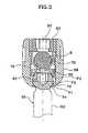
- FIG. 3is a cross-sectional view illustrating a bone fixation apparatus in accordance with an embodiment of the present invention
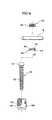
- FIG. 4is an exploded perspective view illustrating the bone fixation apparatus according to the present invention.
- FIG. 5is a cross-sectional view illustrating the receiver member of FIG. 3 ;
- FIG. 6is a cross-sectional view illustrating the cap member of FIG. 3 ;
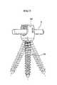
- FIG. 7is a perspective view illustrating the in-use status of the bone fixation apparatus according to the present invention.
- FIG. 8is a graph reflecting the results of tests conducted with respect to the present bone fixation apparatus and the conventional bone fixation apparatuses.
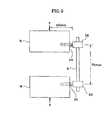
- FIG. 9is a schematic view for explaining a condition under which each bone fixation apparatus is tested.
- a bone fixation apparatusin accordance with an embodiment of the present invention includes a bone screw 50 which has external threads 52 and a head 54 .
- An upper part of the head 54 of the bone screw 52is supported by a cap member 56 .
- the bone fixation apparatusfurther includes a receiver member 58 in which the head 54 , the cap member 56 and a support bar R are accommodated and fixedly held.
- a compression member 60 for fixing the support bar Ris threadedly coupled into an upper part of the receiver member 58 .
- the external threads 52 of the bone screw 50are screwed into a bone.
- the lower end of the external threads 52is pointed to be easily screwed into the bone.
- the root diameter of the external threads 52is gradually decreased toward the lower end, the same crest diameter of the external threads 52 is maintained. If external threads of a bone screw have the same outer diameter and the same thread height throughout the entire length of the bone screw, a problem is caused in that, the bone screw is apt to shake because the fixing force is gradually decreased due to repetitive application of external force, etc.
- the head 54 of the bone screw 50has a truncated sphere-shaped configuration.
- a hexagonal groove 62 of a certain depthis defined on a flat upper end surface of the head 54 so that a tool such as a wrench and the like can be inserted into the hexagonal groove 62 to screw the bone screw 50 into the bone.
- the headmay have a groove of various sectional shapes.
- the cap member 56has a disk-shaped configuration with threads 64 formed on a circumferential outer surface thereof.
- a hole 66is defined through a center portion of the cap member 56 to communicate with the hexagonal groove 62 .
- a recess 68 of a certain depthis defined on a lower surface of the cap member 56 .
- the recess 68possesses a rounded surface which has a radius of a curvature less than that of the head 54 .
- the recess 68may have a truncated cone-shaped contour.
- the threads 64comprise trapezoidal threads in the same manner as the internal threads formed on the inner surface of the receiver member 58 which defines a bore.
- the receiver member 58has the bore 70 which extends in an axial direction and in which the cap member 56 and the head 54 of the bone screw 50 are respectively accommodated and fixedly held.
- the receiver member 58further has a U-shaped channel 72 through which the support bar R extends.
- Two stepped portions 74are formed at a lower end and inner surface of the receiver member 58 to increase the supporting force for the head 54 . Edges P 1 and P 2 of the stepped portions 74 are brought into linear contact with an outer surface of a lower part of the head 54 . It is to be readily understood that three or four stepped portions 74 may be formed in place of the two stepped portions 74 .
- the upper edge P 2 of an upper stepped portion 74has an inner diameter greater than that of the lower edge P 1 of the lower stepped portion 74 , in which the edges P 1 and P 2 of the stepped portions 74 can be brought into linear contact with the outer surface of the lower part of the spherical head 54 .
- the bore 70is formed therein with stepped portions 74 , an accommodating chamber 76 defined above the stepped portions 74 to accommodate the cap member 56 , and internal threads 78 on which the cap member 56 is threadedly moved and to which the compression member 60 is threadedly coupled.
- the accommodating chamber 76has an inner diameter greater than that of the internal threads 78 . Accordingly, the cap member 56 which is inserted into the accommodating chamber 76 after moving on the internal threads 78 is prevented from being unintentionally and upwardly released from the receiver member 58 .
- the upper portion of the internal threads 78has a thread height H 1 greater than that of the thread height H 2 of the lower portion of the internal threads 78 , so that the cap member 56 can be threadedly moved on both of the upper and lower portions of the internal threads 78 but the compression member 60 can be threadedly moved only on the upper portion and cannot be threadedly moved on the lower portion of the internal threads 78 .
- the upper and lower portions of the internal threads 78have the same thread pitch. Therefore, the compression member 60 is screwed only up to such a depth to downwardly bias the support bar R. In this regard, due to the fact that the compression member 60 can be positioned in a proper place even when the support bar R is not inserted through the U-shaped channel 72 , assembly of the bone fixation apparatus can easily be performed within a short period of time.
- the internal threads 78comprise trapezoidal threads, so that deformation of the receiver member 58 can be prevented and the internal threads 78 can provide optimized results in terms of force transfer, locking efficiency, and likelihood of unscrewing.
- a triangular threadas the compression member 60 is screwed, while excellent locking force can be obtained, an axial force transfer rate becomes low.
- a disadvantageis caused in that a separate cap member must be coupled to the receiver member 58 .
- a square threadsuffers from defects in that, while an excellent axial force transfer rate is obtained, the likelihood of unscrewing is increased.
- trapezoidal threadsdue to the fact that trapezoidal threads are adopted, optimized results are provided in terms of force transfer and locking efficiency, and it is not necessary to couple a separate cap member to the receiver member.
- the trapezoidal threadhas an upper surface which is formed to have a slope F 1 greater than the slope F 2 of a lower surface.
- the cap member 56 and the compression member 60can be easily assembled while preventing the cap member 56 from being unintentionally unscrewed.
- the upper and lower surfaces of the trapezoidal threadhave slopes F 1 and F 2 of 10° and 1°, respectively. Since the upper slope is greater than the lower slope, the cap member 56 and the compression member 60 can be easily screwed downward. Also, deformation is minimized even when a force is upwardly applied. Moreover, as engagement between the internal threads 78 and the compression member 60 is maximized, precision is improved and unintentional unscrewing of the compression member 60 is avoided.
- the compression member 60has a cylinder-shaped configuration with threads 80 formed on a circumferential outer surface thereof.
- the threads 80are threadedly coupled to the internal threads 78 of the receiver member 58 .
- a hexagonal groove 82 and a hole 84 which communicate with each otherare defined at a center portion of the compression member 60 .
- the bone screw 50is inserted downward into the bore 70 of the receiver member 58 , in a manner such that the head 54 is seated on the multiple stepped portions 74 .
- the cap member 56is moved downward through the internal threads 78 to be positioned in the accommodating chamber 76 .
- a punching processmay be implemented in such a way as to leave a scar on the upper surface of the cap member 56 .
- the bone screw 50is driven into the bone.
- the support bar Ris inserted through the U-shaped channel 72 to be placed over the cap member 56 , and the compression member 60 is screwed into the receiver member 58 so as to fix the bone screw 50 .
- the locking force of the compression member 60is transferred through the support bar R and the cap member 56 to the head 54 .
- the cap member 56is brought into linear contact with the outer surface of the upper part of the head 54 .
- the bone screw 50is securely fixed to prevent movement.
- the bone screw 50can be fixed in a state wherein it is inclined within 26° when measured from a center axis.
- FIG. 8is a graph obtained by testing the present bone fixation apparatus and the conventional bone fixation apparatuses in terms of the supporting force of the bone screws. In each test, a compression member is screwed into a receiver member with a locking torque of 14 Nm, and a displacement is measured when a head yielded under static load application.
- a universal compression tester having Model No. MTS 793was used as a test equipment, and each test was implemented in accordance with ASTM F1717.
- FIG. 9is a schematic view for explaining a condition under which each bone fixation apparatus is tested.
- bone screws 50are driven into upper and lower objects M to have a spacing of 76 mm.
- the support bar Ris inserted through the receiver members 58 of the bone screws 50 , and compression members (not shown) are screwed into the receiver members 58 .
- compression members(not shown) are screwed into the receiver members 58 .
- by applying a load F to each bone screw at a location separated by 40 mm from a head of each bone screwdeformation of the corresponding object was observed to produce the graph as depicted in FIG. 8 .
- curve Arepresents the bone fixation apparatus manufactured according to the present invention
- curve Brepresents the conventional bone fixation apparatus manufactured according to U.S. Pat. No. 6,280,442
- curve Crepresents the conventional bone fixation apparatus manufactured according to Korean Patent Laid-open Publication No. 2000-48562.
- the bone fixation apparatus according to the present inventionhas a yielding point of 550 N
- the conventional bone fixation apparatusesrespectively have yielding points of 450 N and 300 N. Therefore, it is to be readily understood that the bone fixation apparatus according to the present invention provides increased supporting force.
- the bone fixation apparatusprovides advantages in that the supporting force of a bone screw is increased to prevent movement of a bone and assemblability of the bone fixation apparatus is improved. Further, in the bone fixation apparatus according to the present invention, the force transmission rate is increased, and unintentional unscrewing of a compression member is avoided.
Landscapes
- Health & Medical Sciences (AREA)
- Orthopedic Medicine & Surgery (AREA)
- Life Sciences & Earth Sciences (AREA)
- Neurology (AREA)
- Surgery (AREA)
- Heart & Thoracic Surgery (AREA)
- Engineering & Computer Science (AREA)
- Biomedical Technology (AREA)
- Nuclear Medicine, Radiotherapy & Molecular Imaging (AREA)
- Medical Informatics (AREA)
- Molecular Biology (AREA)
- Animal Behavior & Ethology (AREA)
- General Health & Medical Sciences (AREA)
- Public Health (AREA)
- Veterinary Medicine (AREA)
- Surgical Instruments (AREA)
- Prostheses (AREA)
- Orthopedics, Nursing, And Contraception (AREA)
Abstract
Description
Claims (7)
Applications Claiming Priority (2)
| Application Number | Priority Date | Filing Date | Title |
|---|---|---|---|
| KR1020010067394AKR100379194B1 (en) | 2001-10-31 | 2001-10-31 | Apparatus for fixing bone |
| PCT/KR2002/000159WO2003037199A1 (en) | 2001-10-31 | 2002-02-04 | Bone fixation apparatus |
Publications (2)
| Publication Number | Publication Date |
|---|---|
| US20030158552A1 US20030158552A1 (en) | 2003-08-21 |
| US6905500B2true US6905500B2 (en) | 2005-06-14 |
Family
ID=19715558
Family Applications (1)
| Application Number | Title | Priority Date | Filing Date |
|---|---|---|---|
| US10/296,609Expired - LifetimeUS6905500B2 (en) | 2001-10-31 | 2002-02-04 | Bone fixation apparatus |
Country Status (9)
| Country | Link |
|---|---|
| US (1) | US6905500B2 (en) |
| EP (1) | EP1439788B1 (en) |
| JP (1) | JP2005507282A (en) |
| KR (1) | KR100379194B1 (en) |
| CN (1) | CN100400006C (en) |
| AT (1) | ATE398971T1 (en) |
| DE (1) | DE60227273D1 (en) |
| ES (1) | ES2314038T3 (en) |
| WO (1) | WO2003037199A1 (en) |
Cited By (92)
| Publication number | Priority date | Publication date | Assignee | Title |
|---|---|---|---|---|
| US20040102781A1 (en)* | 2002-11-25 | 2004-05-27 | U & I Corporation | Bone fixation apparatus, method and tool for assembling the same |
| US20040186474A1 (en)* | 2002-12-02 | 2004-09-23 | Biedermann Motech Gmbh | Implant having a shaft and a holding element connected therewith for connecting with a rod |
| US20040186473A1 (en)* | 2003-03-21 | 2004-09-23 | Cournoyer John R. | Spinal fixation devices of improved strength and rigidity |
| US20050216000A1 (en)* | 2004-03-22 | 2005-09-29 | Innovative Spinal Technologies | Closure member for a medical implant device |
| US20050277919A1 (en)* | 2004-05-28 | 2005-12-15 | Depuy Spine, Inc. | Anchoring systems and methods for correcting spinal deformities |
| US20060058788A1 (en)* | 2004-08-27 | 2006-03-16 | Hammer Michael A | Multi-axial connection system |
| US20060084981A1 (en)* | 2004-10-20 | 2006-04-20 | Endius Incorporated | Apparatus for connecting a longitudinal member to a bone portion |
| US20060276791A1 (en)* | 2002-02-13 | 2006-12-07 | Shluzas Alan E | Methods for connecting a longitudinal member to a bone portion |
| US20060293665A1 (en)* | 2002-02-13 | 2006-12-28 | Shluzas Alan E | Apparatus for connecting a longitudinal member to a bone portion |
| US20070055235A1 (en)* | 2003-02-05 | 2007-03-08 | Pioneer Laboratories, Inc. | Low profile spinal fixation system |
| US20070233063A1 (en)* | 2006-02-15 | 2007-10-04 | Sdgi Holdings, Inc. | Multiple lead bone fixation apparatus |
| US20070270845A1 (en)* | 2003-09-08 | 2007-11-22 | Kohsuke Watanabe | Orthopaedic plate and screw assembly |
| US20070299447A1 (en)* | 2003-09-08 | 2007-12-27 | Kohsuke Watanabe | Orthopaedic plate and screw assembly |
| US20080004623A1 (en)* | 2003-09-08 | 2008-01-03 | Joseph Ferrante | Orthopaedic Implant and Screw Assembly |
| US20080015579A1 (en)* | 2006-04-28 | 2008-01-17 | Whipple Dale E | Large diameter bone anchor assembly |
| US20080015576A1 (en)* | 2006-04-28 | 2008-01-17 | Whipple Dale E | Large diameter bone anchor assembly |
| US20080045953A1 (en)* | 2006-07-14 | 2008-02-21 | Laszlo Garamszegi | Pedicle screw assembly with inclined surface seat |
| US20080045955A1 (en)* | 2006-08-16 | 2008-02-21 | Berrevoets Gregory A | Spinal Rod Anchor Device and Method |
| US20080140135A1 (en)* | 2003-06-27 | 2008-06-12 | Depuy Spine, Inc. | Polyaxial bone screw |
| US20080161853A1 (en)* | 2006-12-28 | 2008-07-03 | Depuy Spine, Inc. | Spine stabilization system with dynamic screw |
| US20080262551A1 (en)* | 2007-04-19 | 2008-10-23 | Zimmer Spine, Inc. | Method and associated instrumentation for installation of spinal dynamic stabilization system |
| US20080281326A1 (en)* | 2007-03-20 | 2008-11-13 | Kohsuke Watanabe | Orthopaedic plate and screw assembly |
| KR100890034B1 (en) | 2008-10-09 | 2009-03-25 | (주)코리아 본 뱅크 | Spinal Screw |
| US20090125071A1 (en)* | 2007-10-23 | 2009-05-14 | Skinlo David M | Shape-changing anatomical anchor |
| US20100023061A1 (en)* | 2008-07-24 | 2010-01-28 | Randol David S | Locking mechanism with two-piece washer |
| US20100094349A1 (en)* | 2004-08-27 | 2010-04-15 | Michael Hammer | Multi-Axial Connection System |
| US20100152778A1 (en)* | 2001-03-15 | 2010-06-17 | Stryker Spine | Anchoring member with safety ring |
| US20100152787A1 (en)* | 2007-07-26 | 2010-06-17 | Biotechni America Spine Group, Inc. | Spinal fixation assembly |
| US20100160978A1 (en)* | 2008-12-23 | 2010-06-24 | John Carbone | Bone screw assembly with non-uniform material |
| US20100241175A1 (en)* | 2009-03-20 | 2010-09-23 | Spinal USA LLC | Pedicle screws and methods of using the same |
| US7854751B2 (en) | 2003-12-16 | 2010-12-21 | Dupuy Spine, Inc. | Percutaneous access devices and bone anchor assemblies |
| US20110015678A1 (en)* | 2004-11-23 | 2011-01-20 | Jackson Roger P | Spinal fixation tool set and method |
| US7905907B2 (en) | 2003-10-21 | 2011-03-15 | Theken Spine, Llc | Internal structure stabilization system for spanning three or more structures |
| US7918857B2 (en) | 2006-09-26 | 2011-04-05 | Depuy Spine, Inc. | Minimally invasive bone anchor extensions |
| US20110093021A1 (en)* | 2009-10-16 | 2011-04-21 | Jonathan Fanger | Bone Anchor Assemblies and Methods of Manufacturing and Use Thereof |
| US7942909B2 (en) | 2009-08-13 | 2011-05-17 | Ortho Innovations, Llc | Thread-thru polyaxial pedicle screw system |
| US7942911B2 (en) | 2007-05-16 | 2011-05-17 | Ortho Innovations, Llc | Polyaxial bone screw |
| US7942910B2 (en) | 2007-05-16 | 2011-05-17 | Ortho Innovations, Llc | Polyaxial bone screw |
| US7947065B2 (en) | 2008-11-14 | 2011-05-24 | Ortho Innovations, Llc | Locking polyaxial ball and socket fastener |
| US7951173B2 (en) | 2007-05-16 | 2011-05-31 | Ortho Innovations, Llc | Pedicle screw implant system |
| US7955363B2 (en) | 2002-04-18 | 2011-06-07 | Aesculap Implant Systems, Llc | Screw and rod fixation assembly and device |
| US7967826B2 (en) | 2003-10-21 | 2011-06-28 | Theken Spine, Llc | Connector transfer tool for internal structure stabilization systems |
| US8075603B2 (en) | 2008-11-14 | 2011-12-13 | Ortho Innovations, Llc | Locking polyaxial ball and socket fastener |
| US8197517B1 (en) | 2007-05-08 | 2012-06-12 | Theken Spine, Llc | Frictional polyaxial screw assembly |
| US8197518B2 (en) | 2007-05-16 | 2012-06-12 | Ortho Innovations, Llc | Thread-thru polyaxial pedicle screw system |
| US8361129B2 (en) | 2006-04-28 | 2013-01-29 | Depuy Spine, Inc. | Large diameter bone anchor assembly |
| US8414588B2 (en) | 2007-10-04 | 2013-04-09 | Depuy Spine, Inc. | Methods and devices for minimally invasive spinal connection element delivery |
| US8449544B2 (en) | 2009-06-30 | 2013-05-28 | Smith & Nephew, Inc. | Orthopaedic implant and fastener assembly |
| US8641734B2 (en) | 2009-02-13 | 2014-02-04 | DePuy Synthes Products, LLC | Dual spring posterior dynamic stabilization device with elongation limiting elastomers |
| US20140046374A1 (en)* | 2012-08-09 | 2014-02-13 | Wagdy W. Asaad | Staged Locking of Surgical Screw Assembly |
| US8834469B2 (en) | 2009-06-30 | 2014-09-16 | Smith & Nephew, Inc. | Orthopaedic implant and fastener assembly |
| US9084634B1 (en) | 2010-07-09 | 2015-07-21 | Theken Spine, Llc | Uniplanar screw |
| US9198695B2 (en) | 2010-08-30 | 2015-12-01 | Zimmer Spine, Inc. | Polyaxial pedicle screw |
| US9232968B2 (en) | 2007-12-19 | 2016-01-12 | DePuy Synthes Products, Inc. | Polymeric pedicle rods and methods of manufacturing |
| US9277940B2 (en) | 2008-02-05 | 2016-03-08 | Zimmer Spine, Inc. | System and method for insertion of flexible spinal stabilization element |
| US9320543B2 (en) | 2009-06-25 | 2016-04-26 | DePuy Synthes Products, Inc. | Posterior dynamic stabilization device having a mobile anchor |
| US9445844B2 (en) | 2010-03-24 | 2016-09-20 | DePuy Synthes Products, Inc. | Composite material posterior dynamic stabilization spring rod |
| US9453526B2 (en) | 2013-04-30 | 2016-09-27 | Degen Medical, Inc. | Bottom-loading anchor assembly |
| US9700354B2 (en) | 2004-11-23 | 2017-07-11 | Roger P. Jackson | Polyaxial bone screw with multi-part shank retainer and pressure insert |
| US9999452B2 (en) | 2004-11-23 | 2018-06-19 | Roger P. Jackson | Bone anchor receiver with upper tool engaging grooves and planar faces |
| US10039578B2 (en) | 2003-12-16 | 2018-08-07 | DePuy Synthes Products, Inc. | Methods and devices for minimally invasive spinal fixation element placement |
| US10507043B1 (en) | 2017-10-11 | 2019-12-17 | Seaspine Orthopedics Corporation | Collet for a polyaxial screw assembly |
| US10603083B1 (en) | 2010-07-09 | 2020-03-31 | Theken Spine, Llc | Apparatus and method for limiting a range of angular positions of a screw |
| US10610265B1 (en) | 2017-07-31 | 2020-04-07 | K2M, Inc. | Polyaxial bone screw with increased angulation |
| US10702309B2 (en) | 2004-11-23 | 2020-07-07 | Roger P. Jackson | Pivotal bone anchor assembly with multi-part shank retainer and rod-engaging insert |
| US11419642B2 (en) | 2003-12-16 | 2022-08-23 | Medos International Sarl | Percutaneous access devices and bone anchor assemblies |
| US11717328B2 (en) | 2007-01-22 | 2023-08-08 | Roger P. Jackson | Pivotal bone anchor assembly with twist-in-place insert |
| US11911075B2 (en) | 2012-01-10 | 2024-02-27 | Roger P. Jackson | Pivotal bone anchor assembly with increased shank angulation |
| US11925392B2 (en) | 2007-05-23 | 2024-03-12 | Roger P. Jackson | Pivotal bone anchor assembly with bottom loaded spherical shank head having a planar upper surface |
| US11957386B2 (en) | 2005-09-30 | 2024-04-16 | Roger P. Jackson | Pivotal bone anchor assembly having a downwardly-displaceable snap-in-place insert and method of assembly |
| US11998247B2 (en) | 2009-06-15 | 2024-06-04 | Roger P. Jackson | Method of assembling a pivotal bone anchor assembly using insert tool deployment |
| US12042185B2 (en) | 2010-05-14 | 2024-07-23 | Roger P. Jackson | Pivotal bone anchor assembly with resiliently biased friction fit insert |
| US12053217B2 (en) | 2019-12-17 | 2024-08-06 | Roger P. Jackson | Receiver assembly with rotation blocking side pockets for twist-in-place insert and method of assembly |
| US12070249B2 (en) | 2014-06-04 | 2024-08-27 | Jackson Roger P | Pivotal bone anchor assembly with bottom loaded shank head engaging retainer and closure engaging insert |
| US12082850B2 (en) | 2007-09-17 | 2024-09-10 | Roger P. Jackson | Pivotal bone anchor assembly having twist-in-place insert and receiver with pre-formed axial rotation insert stops |
| US12082852B2 (en) | 2013-03-14 | 2024-09-10 | Medos International Sàrl | Locking compression members for use with bone anchor assemblies and methods |
| US12082854B2 (en) | 2009-06-15 | 2024-09-10 | Roger P. Jackson | Method of assembling a pivotable bone anchor assembly with a slidable retaining structure |
| US12082853B2 (en) | 2014-10-21 | 2024-09-10 | Roger P. Jackson | Pivotal bone anchor assembly with positioner-retainer containment and insert tool deployment |
| US12096964B2 (en) | 2021-07-09 | 2024-09-24 | Roger P. Jackson | Modular bone anchor system with bottom loaded shank heads having a single shank head shape |
| US12102357B2 (en) | 2005-02-22 | 2024-10-01 | Roger P. Jackson | Pivotal bone anchor assembly with cannulated shank having a planar top surface and method of assembly |
| US12127766B2 (en) | 2021-03-05 | 2024-10-29 | Medos International Sàrl | Selectively locking polyaxial screw |
| US12137945B2 (en) | 2018-09-13 | 2024-11-12 | Roger P. Jackson | Pivotal bone anchor system with modular receiver sub-assemblies and universal bone anchors |
| US12185984B2 (en) | 2005-05-27 | 2025-01-07 | Roger P. Jackson | Method of assembling a pivotal bone anchor screw with insert tool deployment |
| US12185983B2 (en) | 2009-06-15 | 2025-01-07 | Roger P. Jackson | Receiver assembly having a vertical tool-engaging slot for independent lock via tooling |
| US12251138B2 (en) | 2014-10-21 | 2025-03-18 | Roger P. Jackson | Pivotal bone anchor assembly with biasing members for pre-lock friction fit |
| US12310631B2 (en) | 2021-03-05 | 2025-05-27 | Medos International Sárl | Multi-feature polyaxial screw |
| US12357348B2 (en) | 2005-09-30 | 2025-07-15 | Roger P. Jackson | Method of assembling a pivotal bone anchor assembly with press-in-place insert |
| US12376886B2 (en) | 2008-08-01 | 2025-08-05 | Roger P. Jackson | Pivotal bone anchor assembly with retainer pre-positioned in expansion chamber and tool-deployable insert |
| US12376894B2 (en) | 2005-07-14 | 2025-08-05 | Roger P. Jackson | Pivotal bone anchor assembly with ring retainer and twist-in-place pressure insert |
| US12402917B2 (en) | 2009-06-15 | 2025-09-02 | Roger P. Jackson | Pivotal bone anchor assembly with independent provisional locking |
| US12414801B2 (en) | 2022-11-03 | 2025-09-16 | Roger P. Jackson | Spinal fixation system with modular receiver sub-assemblies for connecting with bi-spherical universal shank heads |
| US12440245B2 (en) | 2023-09-06 | 2025-10-14 | Pivotable bone anchor assembly with independent provisional locking by insert compressing member |
Families Citing this family (43)
| Publication number | Priority date | Publication date | Assignee | Title |
|---|---|---|---|---|
| US7833250B2 (en)* | 2004-11-10 | 2010-11-16 | Jackson Roger P | Polyaxial bone screw with helically wound capture connection |
| US8377100B2 (en) | 2000-12-08 | 2013-02-19 | Roger P. Jackson | Closure for open-headed medical implant |
| CA2471843C (en)* | 2001-12-24 | 2011-04-12 | Synthes (U.S.A.) | Device for osteosynthesis |
| US11224464B2 (en) | 2002-05-09 | 2022-01-18 | Roger P. Jackson | Threaded closure with inwardly-facing tool engaging concave radiused structures and axial through-aperture |
| US8876868B2 (en) | 2002-09-06 | 2014-11-04 | Roger P. Jackson | Helical guide and advancement flange with radially loaded lip |
| US20060200128A1 (en)* | 2003-04-04 | 2006-09-07 | Richard Mueller | Bone anchor |
| US7377923B2 (en) | 2003-05-22 | 2008-05-27 | Alphatec Spine, Inc. | Variable angle spinal screw assembly |
| US7967850B2 (en) | 2003-06-18 | 2011-06-28 | Jackson Roger P | Polyaxial bone anchor with helical capture connection, insert and dual locking assembly |
| US8926670B2 (en) | 2003-06-18 | 2015-01-06 | Roger P. Jackson | Polyaxial bone screw assembly |
| WO2005065397A2 (en)* | 2003-12-30 | 2005-07-21 | Depuy Spine Sarl | Bone anchor assemblies |
| JP2007516811A (en)* | 2003-12-30 | 2007-06-28 | デピュイ・スパイン・エスエイアールエル | Bone anchor assembly and method for manufacturing bone anchor assembly |
| EP1570794A1 (en)* | 2004-03-04 | 2005-09-07 | U & I Corporation | Bone fixation apparatus, method and tool for assembling the same |
| US7857834B2 (en)* | 2004-06-14 | 2010-12-28 | Zimmer Spine, Inc. | Spinal implant fixation assembly |
| US8926672B2 (en) | 2004-11-10 | 2015-01-06 | Roger P. Jackson | Splay control closure for open bone anchor |
| US9168069B2 (en) | 2009-06-15 | 2015-10-27 | Roger P. Jackson | Polyaxial bone anchor with pop-on shank and winged insert with lower skirt for engaging a friction fit retainer |
| US8444681B2 (en) | 2009-06-15 | 2013-05-21 | Roger P. Jackson | Polyaxial bone anchor with pop-on shank, friction fit retainer and winged insert |
| US7901437B2 (en) | 2007-01-26 | 2011-03-08 | Jackson Roger P | Dynamic stabilization member with molded connection |
| US20070035795A1 (en)* | 2005-08-04 | 2007-02-15 | Hubbard Jason R | Artificial facet joint and a method of making same |
| US7625394B2 (en)* | 2005-08-05 | 2009-12-01 | Warsaw Orthopedic, Inc. | Coupling assemblies for spinal implants |
| US7927359B2 (en) | 2005-10-06 | 2011-04-19 | Paradigm Spine, Llc | Polyaxial screw |
| KR100895243B1 (en)* | 2008-02-27 | 2009-04-30 | 최길운 | Buffered pedicle screws |
| US8998959B2 (en) | 2009-06-15 | 2015-04-07 | Roger P Jackson | Polyaxial bone anchors with pop-on shank, fully constrained friction fit retainer and lock and release insert |
| US9668771B2 (en) | 2009-06-15 | 2017-06-06 | Roger P Jackson | Soft stabilization assemblies with off-set connector |
| US8430917B2 (en)* | 2009-10-30 | 2013-04-30 | Warsaw Orthopedic, Inc. | Bone engaging implant with adjustment saddle |
| ES2525046T3 (en) | 2009-12-21 | 2014-12-16 | Biedermann Technologies Gmbh & Co. Kg | Bone anchoring device |
| CN101816587A (en)* | 2010-04-19 | 2010-09-01 | 天津正天医疗器械有限公司 | Universal pedicle screw for internal fixation of spine |
| GB201006798D0 (en) | 2010-04-23 | 2010-06-09 | Orthofitz Implants Ltd | Spinal implants and spinal fixings |
| CN102309362A (en)* | 2010-07-09 | 2012-01-11 | 顾俊 | Medical universal locking device and using method thereof |
| US20130096618A1 (en)* | 2011-10-14 | 2013-04-18 | Thibault Chandanson | Bone anchor assemblies |
| US8911478B2 (en) | 2012-11-21 | 2014-12-16 | Roger P. Jackson | Splay control closure for open bone anchor |
| CN103040515A (en)* | 2012-12-27 | 2013-04-17 | 苏州欣荣博尔特医疗器械有限公司 | Multi-axial spinal screw |
| US10058354B2 (en) | 2013-01-28 | 2018-08-28 | Roger P. Jackson | Pivotal bone anchor assembly with frictional shank head seating surfaces |
| US8852239B2 (en) | 2013-02-15 | 2014-10-07 | Roger P Jackson | Sagittal angle screw with integral shank and receiver |
| US9566092B2 (en) | 2013-10-29 | 2017-02-14 | Roger P. Jackson | Cervical bone anchor with collet retainer and outer locking sleeve |
| US9717533B2 (en) | 2013-12-12 | 2017-08-01 | Roger P. Jackson | Bone anchor closure pivot-splay control flange form guide and advancement structure |
| US9451993B2 (en) | 2014-01-09 | 2016-09-27 | Roger P. Jackson | Bi-radial pop-on cervical bone anchor |
| US9597119B2 (en) | 2014-06-04 | 2017-03-21 | Roger P. Jackson | Polyaxial bone anchor with polymer sleeve |
| EP2985001B1 (en) | 2014-08-11 | 2017-04-19 | Biedermann Technologies GmbH & Co. KG | Polyaxial bone anchoring device |
| CN108697445B (en) | 2016-02-26 | 2022-04-19 | 美多斯国际有限公司 | Polyaxial bone fixation element |
| US11026730B2 (en) | 2017-05-10 | 2021-06-08 | Medos International Sarl | Bone anchors with drag features and related methods |
| US10736666B2 (en)* | 2017-10-06 | 2020-08-11 | Warsaw Orthopedic, Inc | Spinal implant system and methods of use |
| CN113303897A (en)* | 2021-05-20 | 2021-08-27 | 首都医科大学附属北京朝阳医院 | Assembled cortical bone screw |
| EP4111992B1 (en) | 2021-07-01 | 2024-01-31 | Biedermann Technologies GmbH & Co. KG | Bone anchoring device |
Citations (21)
| Publication number | Priority date | Publication date | Assignee | Title |
|---|---|---|---|---|
| US1328600A (en)* | 1919-06-30 | 1920-01-20 | Walter S Smith | Ball-crank connection |
| US1428715A (en)* | 1921-08-13 | 1922-09-12 | Ira D Shaw | Ball-and-socket joint |
| US3352342A (en)* | 1965-11-26 | 1967-11-14 | Jacobson Harvey | Lock nut |
| US3483888A (en)* | 1967-12-15 | 1969-12-16 | Waldes Kohinoor Inc | Self-locking retaining rings and assemblies employing same |
| US3896867A (en)* | 1972-06-08 | 1975-07-29 | Gkn Screws Fasteners Ltd | Fastener for panels |
| US4319756A (en)* | 1978-08-11 | 1982-03-16 | West & Sons Engineers Limited | Spherical seal element |
| US4628920A (en)* | 1983-12-12 | 1986-12-16 | Synthes Ltd. | Intramedullary nail |
| US4840526A (en)* | 1986-04-17 | 1989-06-20 | Framatome | Gripping device for tensioning screwing elements |
| US5127175A (en)* | 1991-07-10 | 1992-07-07 | Mitch Atkinson | Snow plow support device |
| US5207678A (en) | 1989-07-20 | 1993-05-04 | Prufer | Pedicle screw and receiver member therefore |
| US5443467A (en)* | 1993-03-10 | 1995-08-22 | Biedermann Motech Gmbh | Bone screw |
| US5476464A (en) | 1993-02-25 | 1995-12-19 | Howmedica Gmbh | Device for setting a spine |
| US5554157A (en) | 1995-07-13 | 1996-09-10 | Fastenetix, L.L.C. | Rod securing polyaxial locking screw and coupling element assembly |
| US5865581A (en)* | 1997-04-16 | 1999-02-02 | Huck International, Inc. | Free running prevailing torque nut |
| US6063090A (en)* | 1996-12-12 | 2000-05-16 | Synthes (U.S.A.) | Device for connecting a longitudinal support to a pedicle screw |
| US6280442B1 (en) | 1999-09-01 | 2001-08-28 | Sdgi Holdings, Inc. | Multi-axial bone screw assembly |
| US20010026746A1 (en)* | 2000-03-02 | 2001-10-04 | Frank Calandra | Flange nut |
| US6565567B1 (en)* | 1996-12-20 | 2003-05-20 | Thomas T. Haider | Pedicle screw for osteosynthesis |
| US20030103832A1 (en)* | 2000-05-12 | 2003-06-05 | Karl Cords | Hydraulic device |
| US6648888B1 (en)* | 2002-09-06 | 2003-11-18 | Endius Incorporated | Surgical instrument for moving a vertebra |
| US6733502B2 (en)* | 2002-05-15 | 2004-05-11 | Cross Medical Products, Inc. | Variable locking spinal screw having a knurled collar |
Family Cites Families (2)
| Publication number | Priority date | Publication date | Assignee | Title |
|---|---|---|---|---|
| US5885286A (en)* | 1996-09-24 | 1999-03-23 | Sdgi Holdings, Inc. | Multi-axial bone screw assembly |
| CN1132556C (en)* | 1999-08-24 | 2003-12-31 | 潘显明 | Anti-rotation internal fixator for setting of bone fracture |
- 2001
- 2001-10-31KRKR1020010067394Apatent/KR100379194B1/ennot_activeExpired - Fee Related
- 2002
- 2002-02-04CNCNB028214366Apatent/CN100400006C/ennot_activeExpired - Fee Related
- 2002-02-04EPEP02712487Apatent/EP1439788B1/ennot_activeExpired - Lifetime
- 2002-02-04ATAT02712487Tpatent/ATE398971T1/ennot_activeIP Right Cessation
- 2002-02-04ESES02712487Tpatent/ES2314038T3/ennot_activeExpired - Lifetime
- 2002-02-04DEDE60227273Tpatent/DE60227273D1/ennot_activeExpired - Lifetime
- 2002-02-04WOPCT/KR2002/000159patent/WO2003037199A1/enactiveApplication Filing
- 2002-02-04USUS10/296,609patent/US6905500B2/ennot_activeExpired - Lifetime
- 2002-02-04JPJP2003539547Apatent/JP2005507282A/enactivePending
Patent Citations (21)
| Publication number | Priority date | Publication date | Assignee | Title |
|---|---|---|---|---|
| US1328600A (en)* | 1919-06-30 | 1920-01-20 | Walter S Smith | Ball-crank connection |
| US1428715A (en)* | 1921-08-13 | 1922-09-12 | Ira D Shaw | Ball-and-socket joint |
| US3352342A (en)* | 1965-11-26 | 1967-11-14 | Jacobson Harvey | Lock nut |
| US3483888A (en)* | 1967-12-15 | 1969-12-16 | Waldes Kohinoor Inc | Self-locking retaining rings and assemblies employing same |
| US3896867A (en)* | 1972-06-08 | 1975-07-29 | Gkn Screws Fasteners Ltd | Fastener for panels |
| US4319756A (en)* | 1978-08-11 | 1982-03-16 | West & Sons Engineers Limited | Spherical seal element |
| US4628920A (en)* | 1983-12-12 | 1986-12-16 | Synthes Ltd. | Intramedullary nail |
| US4840526A (en)* | 1986-04-17 | 1989-06-20 | Framatome | Gripping device for tensioning screwing elements |
| US5207678A (en) | 1989-07-20 | 1993-05-04 | Prufer | Pedicle screw and receiver member therefore |
| US5127175A (en)* | 1991-07-10 | 1992-07-07 | Mitch Atkinson | Snow plow support device |
| US5476464A (en) | 1993-02-25 | 1995-12-19 | Howmedica Gmbh | Device for setting a spine |
| US5443467A (en)* | 1993-03-10 | 1995-08-22 | Biedermann Motech Gmbh | Bone screw |
| US5554157A (en) | 1995-07-13 | 1996-09-10 | Fastenetix, L.L.C. | Rod securing polyaxial locking screw and coupling element assembly |
| US6063090A (en)* | 1996-12-12 | 2000-05-16 | Synthes (U.S.A.) | Device for connecting a longitudinal support to a pedicle screw |
| US6565567B1 (en)* | 1996-12-20 | 2003-05-20 | Thomas T. Haider | Pedicle screw for osteosynthesis |
| US5865581A (en)* | 1997-04-16 | 1999-02-02 | Huck International, Inc. | Free running prevailing torque nut |
| US6280442B1 (en) | 1999-09-01 | 2001-08-28 | Sdgi Holdings, Inc. | Multi-axial bone screw assembly |
| US20010026746A1 (en)* | 2000-03-02 | 2001-10-04 | Frank Calandra | Flange nut |
| US20030103832A1 (en)* | 2000-05-12 | 2003-06-05 | Karl Cords | Hydraulic device |
| US6733502B2 (en)* | 2002-05-15 | 2004-05-11 | Cross Medical Products, Inc. | Variable locking spinal screw having a knurled collar |
| US6648888B1 (en)* | 2002-09-06 | 2003-11-18 | Endius Incorporated | Surgical instrument for moving a vertebra |
Non-Patent Citations (1)
| Title |
|---|
| Abstract of Korean Patent 2000-048562. "Multi-Axial Bone Screw Assembly". Mar. 9, 1999. |
Cited By (198)
| Publication number | Priority date | Publication date | Assignee | Title |
|---|---|---|---|---|
| US20120179206A1 (en)* | 2001-03-15 | 2012-07-12 | Stryker Spine | Anchoring member with safety ring |
| US9532807B2 (en) | 2001-03-15 | 2017-01-03 | Stryker European Holdings I, Llc | Anchoring member with safety ring |
| US8845695B2 (en)* | 2001-03-15 | 2014-09-30 | Stryker Spine | Anchoring member with safety ring |
| US20100152778A1 (en)* | 2001-03-15 | 2010-06-17 | Stryker Spine | Anchoring member with safety ring |
| US8167916B2 (en)* | 2001-03-15 | 2012-05-01 | Stryker Spine | Anchoring member with safety ring |
| US8936624B2 (en) | 2002-02-13 | 2015-01-20 | Zimmer Spine, Inc. | Methods for connecting a longitudinal member to a bone portion |
| US9848913B2 (en) | 2002-02-13 | 2017-12-26 | Zimmer Spine, Inc. | Methods for connecting a longitudinal member to a bone portion |
| US20060276791A1 (en)* | 2002-02-13 | 2006-12-07 | Shluzas Alan E | Methods for connecting a longitudinal member to a bone portion |
| US20060293665A1 (en)* | 2002-02-13 | 2006-12-28 | Shluzas Alan E | Apparatus for connecting a longitudinal member to a bone portion |
| US7604656B2 (en)* | 2002-02-13 | 2009-10-20 | Zimmer Spine, Inc. | Apparatus for connecting a longitudinal member to a bone portion |
| US7879075B2 (en) | 2002-02-13 | 2011-02-01 | Zimmer Spine, Inc. | Methods for connecting a longitudinal member to a bone portion |
| US10219835B2 (en) | 2002-02-13 | 2019-03-05 | Zimmer Spine, Inc. | Systems and devices for connecting a longitudinal member to a bone portion |
| US8409255B2 (en) | 2002-04-18 | 2013-04-02 | Aesculap Implant Systems, Llc | Screw and rod fixation assembly and device |
| US7955363B2 (en) | 2002-04-18 | 2011-06-07 | Aesculap Implant Systems, Llc | Screw and rod fixation assembly and device |
| US20040102781A1 (en)* | 2002-11-25 | 2004-05-27 | U & I Corporation | Bone fixation apparatus, method and tool for assembling the same |
| US7335202B2 (en)* | 2002-12-02 | 2008-02-26 | Biedermann Motech Gmbh | Implant having a shaft and a hold element connected therewith for connecting with a rod |
| US20080167689A1 (en)* | 2002-12-02 | 2008-07-10 | Biedermann Motech Gmbh | Implant having a shaft and a holding element connected therewith for connecting with a rod |
| US20040186474A1 (en)* | 2002-12-02 | 2004-09-23 | Biedermann Motech Gmbh | Implant having a shaft and a holding element connected therewith for connecting with a rod |
| US8075590B2 (en) | 2003-02-05 | 2011-12-13 | Pioneer Surgical Technology, Inc. | Low profile spinal fixation system |
| US20070055235A1 (en)* | 2003-02-05 | 2007-03-08 | Pioneer Laboratories, Inc. | Low profile spinal fixation system |
| US20040186473A1 (en)* | 2003-03-21 | 2004-09-23 | Cournoyer John R. | Spinal fixation devices of improved strength and rigidity |
| US10980574B2 (en) | 2003-06-27 | 2021-04-20 | Medos International Sarl | Polyaxial bone screw |
| US7682377B2 (en) | 2003-06-27 | 2010-03-23 | Depuy Spine, Inc. | Polyaxial bone screw |
| US9463049B2 (en) | 2003-06-27 | 2016-10-11 | DePuy Synthes Products, Inc. | Polyaxial bone screw |
| US8313516B2 (en) | 2003-06-27 | 2012-11-20 | Depuy Spine, Inc. | Polyaxial bone screw |
| US9655657B2 (en) | 2003-06-27 | 2017-05-23 | DePuy Synthes Products, Inc. | Polyaxial bone screw |
| US10136924B2 (en) | 2003-06-27 | 2018-11-27 | DePuy Synthes Products, Inc. | Polyaxial bone screw |
| US20080140135A1 (en)* | 2003-06-27 | 2008-06-12 | Depuy Spine, Inc. | Polyaxial bone screw |
| US8663288B2 (en) | 2003-06-27 | 2014-03-04 | Depuy Synthes Products Llc | Polyaxial bone screw |
| US9155579B2 (en) | 2003-06-27 | 2015-10-13 | DePuy Synthes Products, Inc. | Polyaxial bone screw |
| US20100131018A1 (en)* | 2003-06-27 | 2010-05-27 | Depuy Spine, Inc. | Polyaxial bone screw |
| US7799030B2 (en) | 2003-09-08 | 2010-09-21 | Smith & Nephew, Inc. | Orthopaedic plate and screw assembly |
| US20110087228A1 (en)* | 2003-09-08 | 2011-04-14 | Smith & Nephew, Inc. | Orthopaedic Plate and Fastener Assembly |
| US20080004623A1 (en)* | 2003-09-08 | 2008-01-03 | Joseph Ferrante | Orthopaedic Implant and Screw Assembly |
| US20090209961A1 (en)* | 2003-09-08 | 2009-08-20 | Smith & Nephew, Inc., A Delaware Corporation | Orthopaedic implant and fastener assembly |
| US20070299447A1 (en)* | 2003-09-08 | 2007-12-27 | Kohsuke Watanabe | Orthopaedic plate and screw assembly |
| US7883509B2 (en) | 2003-09-08 | 2011-02-08 | Smith & Nephew, Inc. | Orthopaedic implant and screw assembly |
| US20070270845A1 (en)* | 2003-09-08 | 2007-11-22 | Kohsuke Watanabe | Orthopaedic plate and screw assembly |
| US8105326B2 (en) | 2003-09-08 | 2012-01-31 | Smith & Nephew, Inc. | Orthopaedic implant and fastener assembly |
| US7931652B2 (en) | 2003-09-08 | 2011-04-26 | Smith & Nephew, Inc. | Orthopaedic plate and screw assembly |
| US20080033430A1 (en)* | 2003-09-08 | 2008-02-07 | Joseph Ferrante | Orthopaedic Plate and Screw Assembly |
| US7780667B2 (en) | 2003-09-08 | 2010-08-24 | Smith & Nephew, Inc. | Orthopaedic plate and screw assembly |
| US8187275B2 (en) | 2003-09-08 | 2012-05-29 | Smith & Nephew, Inc. | Orthopaedic implant and fastening assembly |
| US8617161B2 (en) | 2003-09-08 | 2013-12-31 | Smith & Nephew, Inc. | Orthopaedic plate and fastener assembly |
| US20110060337A1 (en)* | 2003-09-08 | 2011-03-10 | Smith & Nephew, Inc. | Orthopaedic Implant and Fastener Assembly |
| US8298234B2 (en) | 2003-09-08 | 2012-10-30 | Smith & Nephew, Inc. | Orthopaedic implant and fastener assembly |
| US20080188853A1 (en)* | 2003-09-08 | 2008-08-07 | Joseph Ferrante | Orthopaedic implant and fastening assembly |
| US7905907B2 (en) | 2003-10-21 | 2011-03-15 | Theken Spine, Llc | Internal structure stabilization system for spanning three or more structures |
| US7967826B2 (en) | 2003-10-21 | 2011-06-28 | Theken Spine, Llc | Connector transfer tool for internal structure stabilization systems |
| US8617210B2 (en) | 2003-12-16 | 2013-12-31 | Depuy Spine, Sarl | Percutaneous access devices and bone anchor assemblies |
| US10299839B2 (en) | 2003-12-16 | 2019-05-28 | Medos International Sárl | Percutaneous access devices and bone anchor assemblies |
| US11426216B2 (en) | 2003-12-16 | 2022-08-30 | DePuy Synthes Products, Inc. | Methods and devices for minimally invasive spinal fixation element placement |
| US10039578B2 (en) | 2003-12-16 | 2018-08-07 | DePuy Synthes Products, Inc. | Methods and devices for minimally invasive spinal fixation element placement |
| US8518082B2 (en) | 2003-12-16 | 2013-08-27 | Depuy Spine, Sarl | Percutaneous access devices and bone anchor assemblies |
| US9439699B2 (en) | 2003-12-16 | 2016-09-13 | Medos International Sarl | Percutaneous access devices and bone anchor assemblies |
| US7854751B2 (en) | 2003-12-16 | 2010-12-21 | Dupuy Spine, Inc. | Percutaneous access devices and bone anchor assemblies |
| US11419642B2 (en) | 2003-12-16 | 2022-08-23 | Medos International Sarl | Percutaneous access devices and bone anchor assemblies |
| US7214227B2 (en) | 2004-03-22 | 2007-05-08 | Innovative Spinal Technologies | Closure member for a medical implant device |
| US20050216000A1 (en)* | 2004-03-22 | 2005-09-29 | Innovative Spinal Technologies | Closure member for a medical implant device |
| US8540754B2 (en) | 2004-05-28 | 2013-09-24 | DePuy Synthes Products, LLC | Anchoring systems and methods for correcting spinal deformities |
| US7901435B2 (en) | 2004-05-28 | 2011-03-08 | Depuy Spine, Inc. | Anchoring systems and methods for correcting spinal deformities |
| US20110077688A1 (en)* | 2004-05-28 | 2011-03-31 | Depuy Spine, Inc. | Anchoring systems and methods for correcting spinal deformities |
| US20050277919A1 (en)* | 2004-05-28 | 2005-12-15 | Depuy Spine, Inc. | Anchoring systems and methods for correcting spinal deformities |
| US8992578B2 (en) | 2004-05-28 | 2015-03-31 | Depuy Synthes Products Llc | Anchoring systems and methods for correcting spinal deformities |
| US8951290B2 (en) | 2004-08-27 | 2015-02-10 | Blackstone Medical, Inc. | Multi-axial connection system |
| US8709051B2 (en) | 2004-08-27 | 2014-04-29 | Blackstone Medical, Inc. | Multi-axial connection system |
| US20100094349A1 (en)* | 2004-08-27 | 2010-04-15 | Michael Hammer | Multi-Axial Connection System |
| US20100256681A1 (en)* | 2004-08-27 | 2010-10-07 | Hammer Michael A | Multi-axial connection system |
| US20060058788A1 (en)* | 2004-08-27 | 2006-03-16 | Hammer Michael A | Multi-axial connection system |
| US9375236B2 (en) | 2004-08-27 | 2016-06-28 | Blackstone Medical, Inc. | Multi-axial connection system |
| US20060084981A1 (en)* | 2004-10-20 | 2006-04-20 | Endius Incorporated | Apparatus for connecting a longitudinal member to a bone portion |
| US8366747B2 (en) | 2004-10-20 | 2013-02-05 | Zimmer Spine, Inc. | Apparatus for connecting a longitudinal member to a bone portion |
| US12262920B2 (en) | 2004-11-23 | 2025-04-01 | Roger P. Jackson | Method of assembling a bottom-loaded pivotal bone anchor assembly with compression insert and two-part shank retainer |
| US10617452B2 (en) | 2004-11-23 | 2020-04-14 | Nuvasive, Inc. | Spinal fixation tool set and method |
| US10039577B2 (en) | 2004-11-23 | 2018-08-07 | Roger P Jackson | Bone anchor receiver with horizontal radiused tool attachment structures and parallel planar outer surfaces |
| US10702309B2 (en) | 2004-11-23 | 2020-07-07 | Roger P. Jackson | Pivotal bone anchor assembly with multi-part shank retainer and rod-engaging insert |
| US10398474B2 (en) | 2004-11-23 | 2019-09-03 | Roger P. Jackson | Pivotal bone anchor assembly with pre-loaded multi-part shank retainer and pressure insert |
| US20110015678A1 (en)* | 2004-11-23 | 2011-01-20 | Jackson Roger P | Spinal fixation tool set and method |
| US9999452B2 (en) | 2004-11-23 | 2018-06-19 | Roger P. Jackson | Bone anchor receiver with upper tool engaging grooves and planar faces |
| US9987054B2 (en)* | 2004-11-23 | 2018-06-05 | Roger P. Jackson | Spinal fixation tool set and method |
| US9700354B2 (en) | 2004-11-23 | 2017-07-11 | Roger P. Jackson | Polyaxial bone screw with multi-part shank retainer and pressure insert |
| US10085774B2 (en) | 2004-11-23 | 2018-10-02 | Roger P. Jackson | Polyaxial bone screw with multi-part shank retainer and pressure insert |
| US20160302835A1 (en)* | 2004-11-23 | 2016-10-20 | Roger P. Jackson | Spinal fixation tool set and method |
| US11076889B2 (en) | 2004-11-23 | 2021-08-03 | Roger P. Jackson | Pivotable bone anchor assembly with pre-loaded multi-part retainer and pressure insert |
| US11389214B2 (en) | 2004-11-23 | 2022-07-19 | Roger P. Jackson | Spinal fixation tool set and method |
| US10751095B2 (en) | 2004-11-23 | 2020-08-25 | Roger P. Jackson | Closures with splay resisting threads for bone anchor receivers having horizontal radiused tool attachment grooves |
| US10736673B2 (en) | 2004-11-23 | 2020-08-11 | Roger P. Jackson | Bone anchor receiver with anti-splay tool attachment structure |
| US9211150B2 (en)* | 2004-11-23 | 2015-12-15 | Roger P. Jackson | Spinal fixation tool set and method |
| US11523847B2 (en) | 2004-11-23 | 2022-12-13 | Roger P. Jackson | Fasteners with interlocking gripping threads for bone anchor receivers |
| US11737789B2 (en) | 2004-11-23 | 2023-08-29 | Roger P. Jackson | Pivotal bone anchor assembly with pre-loaded retainer and bottom loaded cannulated screw having a planar top surface |
| US12102357B2 (en) | 2005-02-22 | 2024-10-01 | Roger P. Jackson | Pivotal bone anchor assembly with cannulated shank having a planar top surface and method of assembly |
| US12185984B2 (en) | 2005-05-27 | 2025-01-07 | Roger P. Jackson | Method of assembling a pivotal bone anchor screw with insert tool deployment |
| US12376894B2 (en) | 2005-07-14 | 2025-08-05 | Roger P. Jackson | Pivotal bone anchor assembly with ring retainer and twist-in-place pressure insert |
| US20070021750A1 (en)* | 2005-07-20 | 2007-01-25 | Shluzas Alan E | Apparatus for connecting a longitudinal member to a bone portion |
| US8167911B2 (en) | 2005-07-20 | 2012-05-01 | Zimmer Spine, Inc. | Apparatus for connecting a longitudinal member to a bone portion |
| US11957386B2 (en) | 2005-09-30 | 2024-04-16 | Roger P. Jackson | Pivotal bone anchor assembly having a downwardly-displaceable snap-in-place insert and method of assembly |
| US12357348B2 (en) | 2005-09-30 | 2025-07-15 | Roger P. Jackson | Method of assembling a pivotal bone anchor assembly with press-in-place insert |
| US20070233063A1 (en)* | 2006-02-15 | 2007-10-04 | Sdgi Holdings, Inc. | Multiple lead bone fixation apparatus |
| US8740947B2 (en)* | 2006-02-15 | 2014-06-03 | Warsaw, Orthopedic, Inc. | Multiple lead bone fixation apparatus |
| US8361129B2 (en) | 2006-04-28 | 2013-01-29 | Depuy Spine, Inc. | Large diameter bone anchor assembly |
| US8133262B2 (en) | 2006-04-28 | 2012-03-13 | Depuy Spine, Inc. | Large diameter bone anchor assembly |
| US20080015576A1 (en)* | 2006-04-28 | 2008-01-17 | Whipple Dale E | Large diameter bone anchor assembly |
| US20080015579A1 (en)* | 2006-04-28 | 2008-01-17 | Whipple Dale E | Large diameter bone anchor assembly |
| US20080045953A1 (en)* | 2006-07-14 | 2008-02-21 | Laszlo Garamszegi | Pedicle screw assembly with inclined surface seat |
| US8137387B2 (en) | 2006-07-14 | 2012-03-20 | Phygen, LLC. | Pedicle screw assembly with inclined surface seat |
| US20080045955A1 (en)* | 2006-08-16 | 2008-02-21 | Berrevoets Gregory A | Spinal Rod Anchor Device and Method |
| US8062340B2 (en) | 2006-08-16 | 2011-11-22 | Pioneer Surgical Technology, Inc. | Spinal rod anchor device and method |
| US8828007B2 (en) | 2006-09-26 | 2014-09-09 | DePuy Synthes Products, LLC | Minimally invasive bone anchor extensions |
| US7918858B2 (en) | 2006-09-26 | 2011-04-05 | Depuy Spine, Inc. | Minimally invasive bone anchor extensions |
| US7918857B2 (en) | 2006-09-26 | 2011-04-05 | Depuy Spine, Inc. | Minimally invasive bone anchor extensions |
| US20080161863A1 (en)* | 2006-12-28 | 2008-07-03 | Depuy Spine, Inc. | Spinal anchoring screw |
| US8409256B2 (en) | 2006-12-28 | 2013-04-02 | Depuy Spine, Inc. | Spinal anchoring screw |
| US9629662B2 (en) | 2006-12-28 | 2017-04-25 | DePuy Synthes Products, Inc. | Spinal anchoring screw |
| US20080161853A1 (en)* | 2006-12-28 | 2008-07-03 | Depuy Spine, Inc. | Spine stabilization system with dynamic screw |
| US11717328B2 (en) | 2007-01-22 | 2023-08-08 | Roger P. Jackson | Pivotal bone anchor assembly with twist-in-place insert |
| US7918853B2 (en) | 2007-03-20 | 2011-04-05 | Smith & Nephew, Inc. | Orthopaedic plate and screw assembly |
| US8939978B2 (en) | 2007-03-20 | 2015-01-27 | Smith & Nephew, Inc. | Orthopaedic plate and screw assembly |
| US20080281326A1 (en)* | 2007-03-20 | 2008-11-13 | Kohsuke Watanabe | Orthopaedic plate and screw assembly |
| USRE47377E1 (en) | 2007-04-19 | 2019-05-07 | Zimmer Spine, Inc. | Method and associated instrumentation for installation of spinal dynamic stabilization system |
| US20080262551A1 (en)* | 2007-04-19 | 2008-10-23 | Zimmer Spine, Inc. | Method and associated instrumentation for installation of spinal dynamic stabilization system |
| US7922725B2 (en) | 2007-04-19 | 2011-04-12 | Zimmer Spine, Inc. | Method and associated instrumentation for installation of spinal dynamic stabilization system |
| US8632572B2 (en) | 2007-04-19 | 2014-01-21 | Zimmer Spine, Inc. | Method and associated instrumentation for installation of spinal dynamic stabilization system |
| US20110166604A1 (en)* | 2007-04-19 | 2011-07-07 | Zimmer Spine, Inc. | Method and associated instrumentation for installation of spinal dynamic stabilization system |
| USRE47646E1 (en) | 2007-04-19 | 2019-10-15 | Zimmer Spine, Inc. | Method and associated instrumentation for installation of spinal dynamic stabilization system |
| US8197517B1 (en) | 2007-05-08 | 2012-06-12 | Theken Spine, Llc | Frictional polyaxial screw assembly |
| US7951173B2 (en) | 2007-05-16 | 2011-05-31 | Ortho Innovations, Llc | Pedicle screw implant system |
| US8197518B2 (en) | 2007-05-16 | 2012-06-12 | Ortho Innovations, Llc | Thread-thru polyaxial pedicle screw system |
| US7942911B2 (en) | 2007-05-16 | 2011-05-17 | Ortho Innovations, Llc | Polyaxial bone screw |
| US7942910B2 (en) | 2007-05-16 | 2011-05-17 | Ortho Innovations, Llc | Polyaxial bone screw |
| US12251139B2 (en) | 2007-05-23 | 2025-03-18 | Roger P. Jackson | Pivotal bone anchor screw with nested two-piece closure and independent locking twist-in-place insert |
| US11925392B2 (en) | 2007-05-23 | 2024-03-12 | Roger P. Jackson | Pivotal bone anchor assembly with bottom loaded spherical shank head having a planar upper surface |
| US20100160980A1 (en)* | 2007-07-26 | 2010-06-24 | Biotechni America Spine Group, Inc. | Spinal fixation assembly |
| US20100152787A1 (en)* | 2007-07-26 | 2010-06-17 | Biotechni America Spine Group, Inc. | Spinal fixation assembly |
| US12082850B2 (en) | 2007-09-17 | 2024-09-10 | Roger P. Jackson | Pivotal bone anchor assembly having twist-in-place insert and receiver with pre-formed axial rotation insert stops |
| US8414588B2 (en) | 2007-10-04 | 2013-04-09 | Depuy Spine, Inc. | Methods and devices for minimally invasive spinal connection element delivery |
| US20090125071A1 (en)* | 2007-10-23 | 2009-05-14 | Skinlo David M | Shape-changing anatomical anchor |
| US9232968B2 (en) | 2007-12-19 | 2016-01-12 | DePuy Synthes Products, Inc. | Polymeric pedicle rods and methods of manufacturing |
| US9277940B2 (en) | 2008-02-05 | 2016-03-08 | Zimmer Spine, Inc. | System and method for insertion of flexible spinal stabilization element |
| US8157846B2 (en) | 2008-07-24 | 2012-04-17 | Ingenium S.A. | Locking mechanism with two-piece washer |
| US20100023061A1 (en)* | 2008-07-24 | 2010-01-28 | Randol David S | Locking mechanism with two-piece washer |
| US12376886B2 (en) | 2008-08-01 | 2025-08-05 | Roger P. Jackson | Pivotal bone anchor assembly with retainer pre-positioned in expansion chamber and tool-deployable insert |
| KR100890034B1 (en) | 2008-10-09 | 2009-03-25 | (주)코리아 본 뱅크 | Spinal Screw |
| US8075603B2 (en) | 2008-11-14 | 2011-12-13 | Ortho Innovations, Llc | Locking polyaxial ball and socket fastener |
| US8465530B2 (en) | 2008-11-14 | 2013-06-18 | Ortho Innovations, Llc | Locking polyaxial ball and socket fastener |
| US7947065B2 (en) | 2008-11-14 | 2011-05-24 | Ortho Innovations, Llc | Locking polyaxial ball and socket fastener |
| US20100160978A1 (en)* | 2008-12-23 | 2010-06-24 | John Carbone | Bone screw assembly with non-uniform material |
| US8641734B2 (en) | 2009-02-13 | 2014-02-04 | DePuy Synthes Products, LLC | Dual spring posterior dynamic stabilization device with elongation limiting elastomers |
| US9254151B2 (en) | 2009-03-20 | 2016-02-09 | Spinal Usa, Inc. | Pedicle screws and methods of using the same |
| US20100241175A1 (en)* | 2009-03-20 | 2010-09-23 | Spinal USA LLC | Pedicle screws and methods of using the same |
| US8241341B2 (en) | 2009-03-20 | 2012-08-14 | Spinal Usa, Inc. | Pedicle screws and methods of using the same |
| US8882809B2 (en) | 2009-03-20 | 2014-11-11 | Spinal Usa, Inc. | Pedicle screws and methods of using the same |
| US12402917B2 (en) | 2009-06-15 | 2025-09-02 | Roger P. Jackson | Pivotal bone anchor assembly with independent provisional locking |
| US12207847B2 (en) | 2009-06-15 | 2025-01-28 | Roger P. Jackson | Modular pivotal bone anchor assembly having pre-loaded insert engageable with restrained pre-loaded expandable retainer |
| US12185983B2 (en) | 2009-06-15 | 2025-01-07 | Roger P. Jackson | Receiver assembly having a vertical tool-engaging slot for independent lock via tooling |
| US12082854B2 (en) | 2009-06-15 | 2024-09-10 | Roger P. Jackson | Method of assembling a pivotable bone anchor assembly with a slidable retaining structure |
| US11998247B2 (en) | 2009-06-15 | 2024-06-04 | Roger P. Jackson | Method of assembling a pivotal bone anchor assembly using insert tool deployment |
| US9320543B2 (en) | 2009-06-25 | 2016-04-26 | DePuy Synthes Products, Inc. | Posterior dynamic stabilization device having a mobile anchor |
| US8449544B2 (en) | 2009-06-30 | 2013-05-28 | Smith & Nephew, Inc. | Orthopaedic implant and fastener assembly |
| US8834469B2 (en) | 2009-06-30 | 2014-09-16 | Smith & Nephew, Inc. | Orthopaedic implant and fastener assembly |
| US7942909B2 (en) | 2009-08-13 | 2011-05-17 | Ortho Innovations, Llc | Thread-thru polyaxial pedicle screw system |
| US8361123B2 (en) | 2009-10-16 | 2013-01-29 | Depuy Spine, Inc. | Bone anchor assemblies and methods of manufacturing and use thereof |
| US9161782B2 (en) | 2009-10-16 | 2015-10-20 | DePuy Synthes Products, Inc. | Bone anchor assemblies and methods of manufacturing and use thereof |
| US20110093021A1 (en)* | 2009-10-16 | 2011-04-21 | Jonathan Fanger | Bone Anchor Assemblies and Methods of Manufacturing and Use Thereof |
| US9445844B2 (en) | 2010-03-24 | 2016-09-20 | DePuy Synthes Products, Inc. | Composite material posterior dynamic stabilization spring rod |
| US12042185B2 (en) | 2010-05-14 | 2024-07-23 | Roger P. Jackson | Pivotal bone anchor assembly with resiliently biased friction fit insert |
| US12329422B2 (en) | 2010-05-14 | 2025-06-17 | Roger P. Jackson | Pivotal bone anchor assembly with resiliently axially compressible shank head and rod engaging insert |
| US12383311B2 (en) | 2010-05-14 | 2025-08-12 | Roger P. Jackson | Pivotal bone anchor assembly and method for use thereof |
| US9084634B1 (en) | 2010-07-09 | 2015-07-21 | Theken Spine, Llc | Uniplanar screw |
| US11213324B2 (en) | 2010-07-09 | 2022-01-04 | Theken Spine, Llc | Apparatus and method for limiting a range of angular positions of a screw |
| US11147594B1 (en) | 2010-07-09 | 2021-10-19 | Theken Spine, Llc | Apparatus and method for limiting a range of angular positions of a screw |
| US12042186B1 (en) | 2010-07-09 | 2024-07-23 | Seaspine Orthopedics Corporation | Apparatus and method for limiting a range of angular positions of a screw |
| US10206717B1 (en) | 2010-07-09 | 2019-02-19 | Theken Spine, Llc | Apparatus and method for limiting a range of angular positions of a screw |
| US9707014B1 (en) | 2010-07-09 | 2017-07-18 | Theken Spine, Llc | Apparatus and method for limiting a range of angular positions of a screw |
| US10603083B1 (en) | 2010-07-09 | 2020-03-31 | Theken Spine, Llc | Apparatus and method for limiting a range of angular positions of a screw |
| US9198695B2 (en) | 2010-08-30 | 2015-12-01 | Zimmer Spine, Inc. | Polyaxial pedicle screw |
| US11911075B2 (en) | 2012-01-10 | 2024-02-27 | Roger P. Jackson | Pivotal bone anchor assembly with increased shank angulation |
| US20140046374A1 (en)* | 2012-08-09 | 2014-02-13 | Wagdy W. Asaad | Staged Locking of Surgical Screw Assembly |
| US10085773B2 (en) | 2012-08-09 | 2018-10-02 | Spinecraft, LLC | Staged locking of surgical screw assembly |
| US9155581B2 (en)* | 2012-08-09 | 2015-10-13 | Spine Craft, LLC | Staged locking of surgical screw assembly |
| US12082852B2 (en) | 2013-03-14 | 2024-09-10 | Medos International Sàrl | Locking compression members for use with bone anchor assemblies and methods |
| US9453526B2 (en) | 2013-04-30 | 2016-09-27 | Degen Medical, Inc. | Bottom-loading anchor assembly |
| US12070249B2 (en) | 2014-06-04 | 2024-08-27 | Jackson Roger P | Pivotal bone anchor assembly with bottom loaded shank head engaging retainer and closure engaging insert |
| US12082853B2 (en) | 2014-10-21 | 2024-09-10 | Roger P. Jackson | Pivotal bone anchor assembly with positioner-retainer containment and insert tool deployment |
| US12167872B2 (en) | 2014-10-21 | 2024-12-17 | Roger P. Jackson | Bottom loaded pivotal bone anchor assembly with locking and blocking rings and insert tool deployment |
| US12251138B2 (en) | 2014-10-21 | 2025-03-18 | Roger P. Jackson | Pivotal bone anchor assembly with biasing members for pre-lock friction fit |
| US10610265B1 (en) | 2017-07-31 | 2020-04-07 | K2M, Inc. | Polyaxial bone screw with increased angulation |
| US11229459B2 (en) | 2017-07-31 | 2022-01-25 | K2M, Inc. | Polyaxial bone screw with increased angulation |
| US12262923B2 (en) | 2017-07-31 | 2025-04-01 | K2M, Inc. | Polyaxial bone screw with increased angulation |
| US10507043B1 (en) | 2017-10-11 | 2019-12-17 | Seaspine Orthopedics Corporation | Collet for a polyaxial screw assembly |
| US11890034B1 (en) | 2017-10-11 | 2024-02-06 | Seaspine Orthopedics Corporation | Collet for a polyaxial screw assembly |
| US12137945B2 (en) | 2018-09-13 | 2024-11-12 | Roger P. Jackson | Pivotal bone anchor system with modular receiver sub-assemblies and universal bone anchors |
| US12053217B2 (en) | 2019-12-17 | 2024-08-06 | Roger P. Jackson | Receiver assembly with rotation blocking side pockets for twist-in-place insert and method of assembly |
| US12364515B2 (en) | 2021-03-05 | 2025-07-22 | Medos International Sàrl | Multi-feature polyaxial screw |
| US12127766B2 (en) | 2021-03-05 | 2024-10-29 | Medos International Sàrl | Selectively locking polyaxial screw |
| US12310631B2 (en) | 2021-03-05 | 2025-05-27 | Medos International Sárl | Multi-feature polyaxial screw |
| US12096964B2 (en) | 2021-07-09 | 2024-09-24 | Roger P. Jackson | Modular bone anchor system with bottom loaded shank heads having a single shank head shape |
| US12414801B2 (en) | 2022-11-03 | 2025-09-16 | Roger P. Jackson | Spinal fixation system with modular receiver sub-assemblies for connecting with bi-spherical universal shank heads |
| US12440245B2 (en) | 2023-09-06 | 2025-10-14 | Pivotable bone anchor assembly with independent provisional locking by insert compressing member |
Also Published As
| Publication number | Publication date |
|---|---|
| ES2314038T3 (en) | 2009-03-16 |
| EP1439788A4 (en) | 2007-06-13 |
| US20030158552A1 (en) | 2003-08-21 |
| CN100400006C (en) | 2008-07-09 |
| JP2005507282A (en) | 2005-03-17 |
| KR100379194B1 (en) | 2003-04-08 |
| ATE398971T1 (en) | 2008-07-15 |
| DE60227273D1 (en) | 2008-08-07 |
| CN1578645A (en) | 2005-02-09 |
| EP1439788B1 (en) | 2008-06-25 |
| WO2003037199A1 (en) | 2003-05-08 |
| EP1439788A1 (en) | 2004-07-28 |
Similar Documents
| Publication | Publication Date | Title |
|---|---|---|
| US6905500B2 (en) | Bone fixation apparatus | |
| US20040102781A1 (en) | Bone fixation apparatus, method and tool for assembling the same | |
| US9788865B2 (en) | Bone anchoring device | |
| US9895173B2 (en) | Element with a shank and a holding element connected to it for connecting to a rod | |
| KR101260512B1 (en) | Bone Anchoring Device | |
| EP1570794A1 (en) | Bone fixation apparatus, method and tool for assembling the same | |
| KR100359666B1 (en) | Fusing member and adjusting tool for it | |
| KR100399660B1 (en) | Fixed member | |
| US9532807B2 (en) | Anchoring member with safety ring | |
| US8998967B2 (en) | Receiving part for receiving a rod for coupling the rod to a bone anchoring element and a bone anchoring device with such a receiving part | |
| KR100589728B1 (en) | Bone fixation | |
| US20130065698A1 (en) | Instrument for assembling a bone anchoring device | |
| US20050240180A1 (en) | Spinal osteosynthesis system comprising a support pad | |
| US11141199B1 (en) | Large shank polyaxial pedicle screw system | |
| KR20040054786A (en) | Device For Joining A Longitudinal Support With A Bone Fixation Means | |
| JP2005245520A (en) | Bone fixation device, assembly method and operating tool | |
| SU1733740A1 (en) | Self-stopping threaded part | |
| HK1036921A1 (en) | Device for joining a longitudinal support and bone fixation means | |
| MXPA00010702A (en) | Backbone osteosynthesis system with collar and lock | |
| HK1036921B (en) | Device for joining a longitudinal support and bone fixation means |
Legal Events
| Date | Code | Title | Description |
|---|---|---|---|
| AS | Assignment | Owner name:U & I CO., LTD., KOREA, REPUBLIC OF Free format text:ASSIGNMENT OF ASSIGNORS INTEREST;ASSIGNORS:JEON, CHANG-HUN;AN, HOWARD S.;KOO, JA-KYO;REEL/FRAME:013923/0586;SIGNING DATES FROM 20021115 TO 20021118 | |
| AS | Assignment | Owner name:U & I CORPORATION, KOREA, REPUBLIC OF Free format text:ASSIGNMENT OF ASSIGNORS INTEREST;ASSIGNORS:JEON, CHANG-HUN;AN, HOWARD S.;KOO, JA-KYO;REEL/FRAME:015303/0012;SIGNING DATES FROM 20021105 TO 20021118 | |
| FEPP | Fee payment procedure | Free format text:PAYOR NUMBER ASSIGNED (ORIGINAL EVENT CODE: ASPN); ENTITY STATUS OF PATENT OWNER: SMALL ENTITY | |
| STCF | Information on status: patent grant | Free format text:PATENTED CASE | |
| FPAY | Fee payment | Year of fee payment:4 | |
| FPAY | Fee payment | Year of fee payment:8 | |
| FEPP | Fee payment procedure | Free format text:PAYOR NUMBER ASSIGNED (ORIGINAL EVENT CODE: ASPN); ENTITY STATUS OF PATENT OWNER: SMALL ENTITY Free format text:PAYER NUMBER DE-ASSIGNED (ORIGINAL EVENT CODE: RMPN); ENTITY STATUS OF PATENT OWNER: SMALL ENTITY | |
| FPAY | Fee payment | Year of fee payment:12 |