US6904920B2 - Method and apparatus for cleaning containers - Google Patents
Method and apparatus for cleaning containersDownload PDFInfo
- Publication number
- US6904920B2 US6904920B2US10/043,716US4371602AUS6904920B2US 6904920 B2US6904920 B2US 6904920B2US 4371602 AUS4371602 AUS 4371602AUS 6904920 B2US6904920 B2US 6904920B2
- Authority
- US
- United States
- Prior art keywords
- water
- cleaning solution
- source
- control valve
- rotor
- Prior art date
- Legal status (The legal status is an assumption and is not a legal conclusion. Google has not performed a legal analysis and makes no representation as to the accuracy of the status listed.)
- Expired - Lifetime, expires
Links
Images


Classifications
- H—ELECTRICITY
- H01—ELECTRIC ELEMENTS
- H01L—SEMICONDUCTOR DEVICES NOT COVERED BY CLASS H10
- H01L21/00—Processes or apparatus adapted for the manufacture or treatment of semiconductor or solid state devices or of parts thereof
- H01L21/67—Apparatus specially adapted for handling semiconductor or electric solid state devices during manufacture or treatment thereof; Apparatus specially adapted for handling wafers during manufacture or treatment of semiconductor or electric solid state devices or components ; Apparatus not specifically provided for elsewhere
- H01L21/67005—Apparatus not specifically provided for elsewhere
- H01L21/67011—Apparatus for manufacture or treatment
- H01L21/67017—Apparatus for fluid treatment
- H01L21/67028—Apparatus for fluid treatment for cleaning followed by drying, rinsing, stripping, blasting or the like
- H01L21/6704—Apparatus for fluid treatment for cleaning followed by drying, rinsing, stripping, blasting or the like for wet cleaning or washing
- B—PERFORMING OPERATIONS; TRANSPORTING
- B08—CLEANING
- B08B—CLEANING IN GENERAL; PREVENTION OF FOULING IN GENERAL
- B08B3/00—Cleaning by methods involving the use or presence of liquid or steam
- B08B3/02—Cleaning by the force of jets or sprays
- B—PERFORMING OPERATIONS; TRANSPORTING
- B08—CLEANING
- B08B—CLEANING IN GENERAL; PREVENTION OF FOULING IN GENERAL
- B08B9/00—Cleaning hollow articles by methods or apparatus specially adapted thereto
- B08B9/08—Cleaning containers, e.g. tanks
- B08B9/0861—Cleaning crates, boxes or the like
- B—PERFORMING OPERATIONS; TRANSPORTING
- B08—CLEANING
- B08B—CLEANING IN GENERAL; PREVENTION OF FOULING IN GENERAL
- B08B9/00—Cleaning hollow articles by methods or apparatus specially adapted thereto
- B08B9/08—Cleaning containers, e.g. tanks
- B08B9/093—Cleaning containers, e.g. tanks by the force of jets or sprays
- H—ELECTRICITY
- H01—ELECTRIC ELEMENTS
- H01L—SEMICONDUCTOR DEVICES NOT COVERED BY CLASS H10
- H01L21/00—Processes or apparatus adapted for the manufacture or treatment of semiconductor or solid state devices or of parts thereof
- H01L21/67—Apparatus specially adapted for handling semiconductor or electric solid state devices during manufacture or treatment thereof; Apparatus specially adapted for handling wafers during manufacture or treatment of semiconductor or electric solid state devices or components ; Apparatus not specifically provided for elsewhere
- H01L21/67005—Apparatus not specifically provided for elsewhere
- H01L21/67011—Apparatus for manufacture or treatment
- H01L21/67017—Apparatus for fluid treatment
- H01L21/67028—Apparatus for fluid treatment for cleaning followed by drying, rinsing, stripping, blasting or the like
- H01L21/6704—Apparatus for fluid treatment for cleaning followed by drying, rinsing, stripping, blasting or the like for wet cleaning or washing
- H01L21/67051—Apparatus for fluid treatment for cleaning followed by drying, rinsing, stripping, blasting or the like for wet cleaning or washing using mainly spraying means, e.g. nozzles
Definitions
- the field of the present inventionrelates to cleaning apparatus for rinsing and drying containers and carriers used to hold and process semiconductor wafers, substrates, flat panel displays and other flat media.
- Flat mediasuch as silicon or other semiconductor wafers, substrates, photomasks, flat panel displays, data disks, and similar articles require extremely low contamination levels. Even minute contaminants can cause defects. Accordingly, it is necessary to maintain a high level of cleanliness during all or nearly all stages of production of these types of flat media.
- the flat media describedmay be referred to below as “wafers”, although it will be understood that “wafers” means any form of flat media.
- Wafersare typically processed in batches. For example, in manufacturing semiconductor chips, for use in computers, telephones, televisions, and other electronic products, silicon wafers will undergo many batch processing steps, such as oxidation, photolithography, diffusion, chemical vapor deposition, metallization and etching. Batch handling may occur throughout the entire production process, or for one or more processing steps or related handling operations. Batch processing of this type almost always utilizes some type of carrier or container to hold the wafers being processed.
- a wafer carrier or containerholds a group of wafers.
- the wafer carrierscan be of various designs, and may be more specifically referred to as a wafer boat. In many applications, they are made of a suitable polymeric material, e.g., polypropylene or TEFLON® fluoropolymer.
- the sides and sometimes the bottom of the wafer boathave receiving slots formed to receive and hold the wafers in a spaced array with the faces of the wafers adjacent to one another. Typically, the central axes of the wafers are aligned.
- the wafersare slid into the carrier or container, such as from the side or above, and are removed by sliding them outwardly.
- the receiving slotsare shallow so that the wafer is engaged only at the peripheral edges and along a thin marginal band extending inwardly from the periphery.
- Wafer carrierscan also be provided in the form of a protective case or box in which the wafers are held and are sealed against contamination during travel within the processing facility. Wafer carriers of this type are frequently designed to hold a wafer boat having a complementary design. The complementary relationship of the protective wafer carrier box and the wafer carrier boat allow the boat and supported wafers to be fully enclosed and securely held in place during transport.
- carrierreferred to below means a carrier, a container, with or without a lid, or a wafer boat.
- the wafer carriersmust be cleaned. Cleaning them is difficult because they typically have features which include slots, grooves or apertures, and inside corners which can trap contaminants. The difficulty in cleaning is enhanced by the extremely low contamination levels which are required for processing the wafers.
- Various machineshave been made and used for cleaning wafer carriers.
- the carriersare mounted on a rotor and spin within a chamber, while cleaning solutions are sprayed onto the carriers.
- the spinning movementminimizes process time and also helps in drying the carriers.
- a surfactantis introduced and mixed with de-ionized water, at a concentration of approximately 1:10,000. Used in this way, the surfactant acts as a wetting agent which helps to remove loosely adhered particles. Typically the surfactant is used only once and then discarded as waste.
- the surfactantis typically held in a vessel from which it must be transferred into the wafer carriers during the cleaning process. Since the surfactant stream is applied in such a small flow volume so as to produce the desired small concentration level, it is difficult to control volume flow of the surfactant into the carriers.
- surfactantis pumped from the bulk storage vessel into a holding tank where it is diluted to a desired level. The diluted surfactant solution is then drawn out of the holding tank by a venturi into the water stream where it is mixed or aspirated with the water. The water and surfactant mixture is then directed to the rinsing manifold ready for injection into the wafer carrier.
- the present inventionis directed to an apparatus for cleaning flat media carriers.
- a rotoris rotatably mounted within a chamber.
- Nozzles within the chamberare arranged to spray a washing mixture of water and a detergent or surfactant onto carriers supported on the rotor.
- the washing mixtureis prepared by drawing out surfactant directly from a surfactant bulk storage vessel by means of a metering pump.
- the flow rate of the wateris measured by a flow meter and in combination with the metering pump, an proper amount of surfactant is injected into the water line to produce a mixture with a desired surfactant concentration for removing contaminants.
- the surfactant solutionis injected into the water line at or upstream of an inline mixing control valve to ensure that the water and surfactant are thoroughly mixed before being injected into the wafer carrier.
- a flow meteris provided in the water inlet line for each manifold and a separate metering pump is provided for injecting surfactant into each water line to ensure that a proper amount of surfactant is injected into each water line to produce a mixture with a desired surfactant concentration.
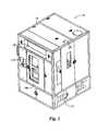
- FIG. 1is a front, top and right side perspective view of the present cleaning apparatus.
- FIG. 2is a back, top and left side perspective view thereof.
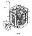
- FIG. 3is a front, top and right side perspective view of the apparatus shown in FIGS. 1 and 2 , with the covers removed.
- FIG. 4is a back, top and left side view thereof.
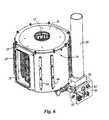
- FIG. 5is a back, top and left side perspective view with various components removed for purposes of illustration.
- FIG. 6is a front, top and right side perspective view of certain major components of the apparatus shown in FIGS. 1-5 .
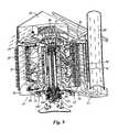
- FIG. 7is a perspective view of the rotor removed from the chamber.
- FIG. 8is a plan view thereof.
- FIG. 9is a section perspective view illustrating air movement through the apparatus.
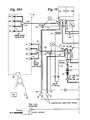
- FIG. 10is a schematic diagram showing fluid flow and interconnections in the present machine.
- FIG. 11is a left front side perspective view of a preferred configuration for the pumping and control valve system of FIG. 10 .
- FIG. 12is a rear right side perspective view of the configuration of FIG. 11 .
- FIG. 13is a schematically illustrated top view showing orientations of spray manifolds and nozzles.
- FIGS. 1 and 2illustrate a carrier cleaning machine 10 having a frame 12 and housing panels 14 forming an enclosure.
- a back door 16 and front door 16 Aare provided on the front and back surfaces of the machine 10 .
- the machine 10is generally installed in a clean room, of the type used in manufacturing semiconductors.
- An air filter enclosure 18is located above the front door 16 A, and contains a filter which filters clean room air.
- An exhaust duct 26extends out of the top of the machine 10 , at the back right corner, and is ordinarily connected to a facility or building exhaust duct.
- a cylindrical chamber 24is supported within the frame 12 .
- the chamber 24has cylindrical side walls 25 and is closed off on the top and bottom by a top plate 36 and a bottom plate 38 .
- the top plate 36has a central opening 37 so that air passing through the filter box 18 can flow into and downwardly through the chamber 24 .
- An exhaust plenum 50 at the lower back and right side of the chamber 24connects to the exhaust duct 26 , for moving air out of the chamber 24 .
- a drain opening 39 at a low point of the chamber 24 , in the exhaust plenum 50drains fluids out of the chamber.
- outer rinse manifolds 28(R 1 -R 4 ), each having e.g., 12 spray nozzles, are positioned around the outside circumference of the chamber 24 , on the chamber cylindrical side walls 25 .
- the outer rinse manifolds 28may be located on the outside of the cylindrical side walls 25 , as shown in FIGS. 4-6 and 10 , or may be on the inside surface of the cylindrical side walls 25 , so long as the rinse spray nozzles 30 on the outer rinse manifolds 28 are appropriately positioned to spray the work pieces, i.e., the wafer carriers.
- Inner rinse manifolds 29are positioned near the center of the chamber 24 , with each inner rinse manifold (R 5 -R 8 ) having a plurality of rinse spray nozzles 30 oriented to spray outwardly onto the work pieces (i.e., wafer carriers, containers or lids).
- work piecesi.e., wafer carriers, containers or lids.
- outer dry manifolds 64(D 5 -D 8 ), each having a plurality of dry spray nozzles 66 , are spaced apart around the circumference of the chamber 24 , on the chamber cylindrical side walls 25 .
- Inner dry manifolds 65(D 1 -D 4 ), each also having a plurality of dry spray nozzles 66 are positioned near the center of the chamber 24 .
- a preferred orientation of the dry manifolds (D 1 -D 8 ) and the rinse manifolds (R 1 -R 8 )is shown in FIG. 13 .
- the outer dry manifolds 64are connected via a distribution manifold 61 and then by fluid lines 63 to a supply 120 of pressurized gas such as air or nitrogen via control valve 63 a .
- the inner dry manifolds 65are connected via a distribution manifold 68 and then by fluid lines 67 to a pressurized gas supply 130 via control valve 67 a .
- the outer rinse manifolds 28are connected via a distribution manifold 141 then by fluid lines 140 to a control valve 170 and a source 110 of de-ionized (DI) water.
- DIde-ionized
- the inner rinse manifolds 29are connected via a distribution manifold 151 and then by fluid lines 150 to a control valve 180 and the DI-water source 110 .
- Pressurized gas linesare also connected to the spray manifolds, for purging, via the control valves 170 , 180 .
- a boost pump 46increases the water pressure of the DI-water from the external source 110 to the rinse manifolds 28 and 29 .
- control valves 170 , 180are preferably mixing control valves which ensure that the surfactant is thoroughly mixed with the DI-water.
- a surfactant tank or bottle 35is connected to surfactant metering pumps 48 and 49 via a fluid line 190 .
- the surfactant metering pump 48is connected to the mixing control valve 170 via fluid lines 192 .
- Pump 48pumps surfactant from the tank or bottle 35 into the control valve 170 where it is mixed with the DI water for injection into the outer rinse manifolds 28 via fluid lines 140 .
- the surfactant metering pump 49is connected to the control valve 180 via fluid lines 194 .
- Pump 49pumps surfactant from the tank or bottle 35 into the control mixing valve 180 where it is mixed with the DI water for injection into the inner rinse manifolds 29 via fluid lines 150 .
- the drain opening 39 at the bottom of the chamber 24leads to a diverter 90 which connects the drain opening 39 to either a reclaim tank 42 or to a facility waste drain 92 .
- a return line 142 from fluid line 192 proximate the mixing control valve 170provides for priming of surfactant (under the control of control valve 145 ) back to vessel 35 ; and a return line 152 from fluid line 194 proximate the mixing control valve 180 provides for priming of surfactant (under the control of control valve 155 ) back to vessel 35 .
- a recirculation line 147 from fluid line 115 proximate the mixing control valve 170provides for recirculation of DI-water; and a recirculation line 157 from fluid line 117 proximate the mixing control valve 180 provides for recirculation of DI-water.
- the recirculation lines 147 and 157provide a flow of water through the tool even when the tool is idle to prevent bacteria formation in lines and valves.
- air heaters 58are provided within an air inlet plenum 56 behind the air filter box 18 and over the center or inlet opening 37 leading into the top of the chamber 24 . Blanket heaters 55 are also provided around the top of the chamber 24 .
- a computer/controller 112is linked to and controls the various pumps, valves, heaters, and flow sensors.
- a rotor 70is rotatably supported within the chamber 24 on a base 104 .
- the rotorhas a top ring 72 and a bottom ring 74 connected by a frame work 75 .
- Ladders 76are pivotally supported on upper and lower ladder supports 82 extending radially outwardly from the top ring 72 and the bottom ring 74 .
- Each ladder 76has a plurality of compartments 78 for holding containers or carriers 85 , or container lids 87 , as shown in FIG. 9 .
- the configuration of the ladders 76 and the design of the compartments 78 on the ladders 76are adapted for the specific sizes and types of carriers, containers, and lids to be cleaned.
- the entire rotor 70is rotatably supported on a center column 100 and a rotor axle 106 within the center column 100 .
- a rotor drive motor 102spins the rotor 70 .
- the detailed design features of the rotor 70 , center column 100 and rotor axle 106are well known, and are described in U.S. Pat. No. 5,224,503, incorporated herein by reference. Alternately, the tool may be constructed with non-rotating ladders.
- the machine 10is typically installed in a silicon wafer or other flat media manufacturing facility. As the wafers are moved through various processing steps, the carriers 85 become contaminated, and must be cleaned before wafers are replaced into the carriers.
- the door 16 or 16 A of the machine 10is opened.
- the rotor 70is turned or indexed until a ladder 76 is aligned with the door.
- the ladder 76is then turned 180° so that the empty compartments 78 can be accessed through the door 16 .
- the carriers 85are loaded into the compartments 78 and the ladder is turned back to its original position, so that the compartments 78 are facing to the inside of the chamber 24 .
- the ladders 76are preferably provided with a latch or detent to lock the ladders into the closed or operating position, with the compartments 78 facing the inside of the chamber 24 .
- the next ladder 76is then brought into alignment with the door, for loading, by turning the rotor 70 (by hand or via control of the rotor drive motor 102 ). Loading continues until all of the ladders 76 are filled.
- a facilities panel 40 on the machine 10has connections to input de-ionized water and gas, e.g., nitrogen or air into the machine 10 , and a connection for the waste drain 92 , as well as gauges and valves for measuring and controlling fluid/gas flow.
- de-ionized water and gase.g., nitrogen or air
- the surfactant tank 35is supplied with a detergent or surfactant, for example, Valtron DP 94001 (a high pH alkaline detergent) a preferred surfactant for removing photoresist.
- a detergent or surfactantfor example, Valtron DP 94001 (a high pH alkaline detergent) a preferred surfactant for removing photoresist.
- surfactantas used in this application means a surfactant or a detergent.
- the controller 112via appropriate control of valves and pumps, delivers DI-water and surfactant into the mixing control valves 170 , 180 to make a desired DI-water/surfactant mixture for injection into each of the rinse manifolds 28 , 29 .
- the DI-water boost pump 46boosts the water pressure in the supply line 114 to deliver DI-water to both mixing control valve 170 and mixing control valve 180 .
- a flow meter 116is disposed in the fluid line upstream of the outer rinse mixing control valve 170 to measure the flow of DI-water being supplied thereto.
- a flow meter 118is disposed in the fluid line upstream of the inner rinse mixing control valve 180 to measure the flow of DI-water being supplied thereto.
- the systemis initially calibrated by using information from the flow meter 116 in combination with controls on the metering pump 48 to set a reasonably precise surfactant concentration for the DI-water/surfactant mixture for injection into the outer rinse manifolds 28 .
- the systemis calibrated by using information from the flow meter 118 in combination controls on the metering pump 49 to set a reasonably precise surfactant concentration for the DI-water/surfactant mixture for injection into the inner rinse manifolds 29 .
- the solutionis 1:10000 surfactant, with the balance being DI-water, for each of the manifolds, but having separate flow control/metering, the surfactant concentration levels may be individually set.
- the metering pumps 48 , 49are preferably a type of positive displacement pump, such as a diaphragm pump.
- the flow rate of such a diaphragm pumpmay be adjusted my adjusting the pump stroke (which sets the pumping volume per stroke) and/or the pump speed (strokes per minute).
- the pumpsare preferably set at a relatively high speed so that surfactant is delivered into the system at a less pulsed/intermittent manner.
- the system operatormay adjust the surfactant/DI-water concentration by adjusting the pump stroke (which sets the pumping volume per stroke) and/or the pump speed (strokes per minute).
- an electronic control systemmay be implemented, using inputs from flow meters 116 , 118 and electronic control of the pumping rates of the metering pumps.
- a low-level sensor 35 amay be provided on the surfactant vessel 35 for alerting that the fluid level in the vessel is low and needs replacement.
- the sensor 35 amay either be a liquid sensor inside the vessel, or capacitive sensor located outside the vessel, or some other suitable device.
- the sensormay just determine when the level has reached a particular (low) level, indicating time for surfactant replacement, or certain types of sensors may provide a signal corresponding to surfactant level.
- the tray 35 b(see FIG. 11 ) in which the vessel 35 is inserted may comprise a load cell supporting the surfactant vessel 35 to provide the weight of the vessel 35 with the change in weight of the vessel as determined by the load cell providing an indication of fluid level.
- the controller 112controls the rotor drive motor 102 , causing the rotor 70 to spin in a first direction, at a low speed, e.g., 1-50 rpm. Via control of the pumps 46 , 48 , 49 and valves 170 , 180 , the DI-water/surfactant solution is sprayed onto the carriers 85 on the spinning rotor.
- the rotor 70reverses direction while the surfactant solution spraying continues, for improved spray coverage.
- the inner rinse manifolds 29located inside of the rotor 70 , spray radially outwardly from the center of the chamber 24 .
- the outer rinse manifolds 28located around the chamber cylindrical side walls 25 spray radially inwardly toward the chamber center. This dual spray action, combined with bi-directional rotation of the rotor 70 , provides virtually complete coverage of all surfaces of the containers 85 .
- the manifoldsare purged by gas or nitrogen flowing through check valves 143 , 153 and the control valves 170 , 180 as shown in FIG. 10 .
- the diverter valve 90is positioned to direct fluid to the facility waste drain 92 .
- the diverter 90remains in position to connect the drain opening 39 to the facility waste drain 92 .
- DI-wateris sprayed onto the carriers 85 from all of the rinse manifolds (R 1 -R 8 ), with the rotor 70 spinning in a first direction, and then reversing and spinning in the opposite direction, e.g., at from 1-50 rpm, preferably about 6 rpm.
- the heaters 58are then turned on, and the rotor accelerated up to e.g., 300 rpm, so that water droplets on the containers 85 are centrifugally flung off of the containers, and the containers are dried.
- the blanket heaters 55are located on the outside of the top of the chamber 24 and are on continuously, for warming the top of the chamber. The DI rinse water goes out the waste drain 92 .
- the diverter valve 90may be switched to a position
- the specific cleaning parameterssuch as duration of surfactant, rinse water, and air/gas spray, rotation speeds and sequences, heater operation, surfactant concentration, etc., may be varied somewhat to achieve optimum results, with different containers and contaminants, as would be apparent to one skilled in the art from the descriptions herein.
- the machineenables use of highly concentrated cleaning solutions, such as surfactants, detergents, and ozonated DI-water, for cleaning containers.
- Solventsalthough not ordinarily preferred, could also be used.
- Surfactantsare generally not flammable or explosive, and do not have the same environmental disadvantages associated with solvents. On the other hand, surfactants can be very expensive, e.g., $40/gallon.
- Using the metering pumps to produce a precise and consistent concentration of surfactant for the DI-water/surfactant mixturethe system conserves surfactant.
- the systemmay also use the surfactant reclamation techniques of U.S. Pat. No. 6,432,214, hereby incorporated by reference.
Landscapes
- Engineering & Computer Science (AREA)
- Physics & Mathematics (AREA)
- Condensed Matter Physics & Semiconductors (AREA)
- General Physics & Mathematics (AREA)
- Manufacturing & Machinery (AREA)
- Computer Hardware Design (AREA)
- Microelectronics & Electronic Packaging (AREA)
- Power Engineering (AREA)
- Mechanical Engineering (AREA)
- Cleaning By Liquid Or Steam (AREA)
Abstract
Description
Claims (19)
Priority Applications (2)
| Application Number | Priority Date | Filing Date | Title |
|---|---|---|---|
| US10/043,716US6904920B2 (en) | 1998-07-10 | 2002-01-09 | Method and apparatus for cleaning containers |
| US11/128,755US20050268944A1 (en) | 1998-07-10 | 2005-05-13 | Method and apparatus for cleaning containers |
Applications Claiming Priority (4)
| Application Number | Priority Date | Filing Date | Title |
|---|---|---|---|
| US09/113,440US6432214B2 (en) | 1998-07-10 | 1998-07-10 | Cleaning apparatus |
| US09/658,395US6797076B1 (en) | 1998-07-10 | 2000-09-08 | Spray nozzle system for a semiconductor wafer container cleaning aparatus |
| US90503001A | 2001-07-12 | 2001-07-12 | |
| US10/043,716US6904920B2 (en) | 1998-07-10 | 2002-01-09 | Method and apparatus for cleaning containers |
Related Parent Applications (1)
| Application Number | Title | Priority Date | Filing Date |
|---|---|---|---|
| US90503001AContinuation | 1998-07-10 | 2001-07-12 |
Related Child Applications (1)
| Application Number | Title | Priority Date | Filing Date |
|---|---|---|---|
| US11/128,755DivisionUS20050268944A1 (en) | 1998-07-10 | 2005-05-13 | Method and apparatus for cleaning containers |
Publications (2)
| Publication Number | Publication Date |
|---|---|
| US20020100495A1 US20020100495A1 (en) | 2002-08-01 |
| US6904920B2true US6904920B2 (en) | 2005-06-14 |
Family
ID=34637054
Family Applications (2)
| Application Number | Title | Priority Date | Filing Date |
|---|---|---|---|
| US10/043,716Expired - LifetimeUS6904920B2 (en) | 1998-07-10 | 2002-01-09 | Method and apparatus for cleaning containers |
| US11/128,755AbandonedUS20050268944A1 (en) | 1998-07-10 | 2005-05-13 | Method and apparatus for cleaning containers |
Family Applications After (1)
| Application Number | Title | Priority Date | Filing Date |
|---|---|---|---|
| US11/128,755AbandonedUS20050268944A1 (en) | 1998-07-10 | 2005-05-13 | Method and apparatus for cleaning containers |
Country Status (1)
| Country | Link |
|---|---|
| US (2) | US6904920B2 (en) |
Cited By (6)
| Publication number | Priority date | Publication date | Assignee | Title |
|---|---|---|---|---|
| US7520286B2 (en) | 2005-12-05 | 2009-04-21 | Semitool, Inc. | Apparatus and method for cleaning and drying a container for semiconductor workpieces |
| US7644512B1 (en)* | 2006-01-18 | 2010-01-12 | Akrion, Inc. | Systems and methods for drying a rotating substrate |
| US20110061690A1 (en)* | 2009-09-11 | 2011-03-17 | Martin Seger | Magazine device for blow moulds, comprising a cleaning device |
| US20120260950A1 (en)* | 2011-04-15 | 2012-10-18 | Stmicroelectronics S.R.L. | Apparatus for processing semiconductor wafers, in particular for carrying out a polymers removal process step |
| US9919939B2 (en) | 2011-12-06 | 2018-03-20 | Delta Faucet Company | Ozone distribution in a faucet |
| US11458214B2 (en) | 2015-12-21 | 2022-10-04 | Delta Faucet Company | Fluid delivery system including a disinfectant device |
Families Citing this family (13)
| Publication number | Priority date | Publication date | Assignee | Title |
|---|---|---|---|---|
| US6923188B2 (en)* | 2003-04-29 | 2005-08-02 | Powerchip Semiconductor Corp. | Method of sampling contaminants of semiconductor wafer carrier |
| WO2006080868A1 (en)* | 2005-01-25 | 2006-08-03 | Gas Turbine Efficiency Ab | Probe cleaning method and apparatus |
| SE531745C2 (en)* | 2007-06-01 | 2009-07-28 | Delaval Holding Ab | Procedure and arrangement for cleaning of milking systems with multiple milking stations |
| WO2009155073A2 (en)* | 2008-05-28 | 2009-12-23 | Poly-Flow Engineering, Llc | Fixture drying apparatus and method |
| JP5341427B2 (en)* | 2008-08-20 | 2013-11-13 | 東京エレクトロン株式会社 | Substrate processing apparatus, substrate processing method, substrate processing program, and computer-readable recording medium recording the substrate processing program |
| IT1395067B1 (en)* | 2009-08-06 | 2012-09-05 | S I A Società Idee Avioniche S R L | DESALINATING WASHING UNIT AND RECOVERY PERFORMANCE FOR TURBOPROPULSORS OF HELICOPTERS AND AIRPLANES |
| CN103170469B (en)* | 2011-12-22 | 2016-02-03 | 中芯国际集成电路制造(上海)有限公司 | For cleaning the device and method with dry wafer cassette |
| US20160303622A1 (en)* | 2013-10-23 | 2016-10-20 | Brooks Ccs Gmbh | Cleaning Systems and Methods for Semiconductor Substrate Storage Articles |
| US10340159B2 (en)* | 2014-06-09 | 2019-07-02 | Ebara Corporation | Cleaning chemical supplying device, cleaning chemical supplying method, and cleaning unit |
| KR102538284B1 (en)* | 2018-07-06 | 2023-05-30 | 쉘백 세미컨덕터 테크놀러지, 엘엘씨 | Systems and methods for spray metering devices |
| HUE062701T2 (en)* | 2019-12-16 | 2023-11-28 | Lvp Eng & Constructions Bvba | Device and method for cleaning containers |
| US11813649B2 (en)* | 2020-05-29 | 2023-11-14 | Taiwan Semiconductor Manufacturing Company Limited | Semiconductor arrangement and method for making |
| CN114632751B (en)* | 2022-03-17 | 2023-12-22 | 北京北方华创微电子装备有限公司 | Cleaning system |
Citations (42)
| Publication number | Priority date | Publication date | Assignee | Title |
|---|---|---|---|---|
| US1264792A (en)* | 1917-06-01 | 1918-04-30 | Chauncey B Hayward | Dish-washing machine. |
| US1915162A (en)* | 1931-03-07 | 1933-06-20 | Frank W Hastings Jr | Dishwashing machine |
| US2197382A (en)* | 1938-02-15 | 1940-04-16 | Eugene V Myers | Dishwashing machine |
| US2562076A (en)* | 1946-02-05 | 1951-07-24 | Weisselberg Arnold | Dishwashing machine with impeller coaxial with jet actuated rotary basket |
| US2669999A (en)* | 1948-12-11 | 1954-02-23 | Frank J Ablah | Dishwashing machine |
| US2830605A (en)* | 1955-07-19 | 1958-04-15 | Winningham Arthur | Container-cleaning device |
| US3095997A (en)* | 1961-05-26 | 1963-07-02 | Superpack Vendin | Device for vending cylindrical objects |
| US3240216A (en)* | 1963-04-30 | 1966-03-15 | Ind Washing Machine Corp | Industrial washing machine |
| US3448744A (en)* | 1967-09-15 | 1969-06-10 | Harry Szczepanski | Indexing vertical rotary mask-washing machine |
| US3534749A (en)* | 1968-11-21 | 1970-10-20 | Arthur Till | Cleaning machines for containers |
| US3620234A (en) | 1969-07-07 | 1971-11-16 | Herbert L Everrood | Air-filter-cleaning apparatus |
| US3724636A (en)* | 1969-02-24 | 1973-04-03 | Exceltronic Ind Ltd | Dishwashing machine |
| US3942545A (en)* | 1973-07-09 | 1976-03-09 | Flynn Edward W | Glass washer and conditioner |
| US4299245A (en) | 1980-04-21 | 1981-11-10 | Clapper Millard F | Filter cleaning system |
| US4437479A (en)* | 1981-12-30 | 1984-03-20 | Atcor | Decontamination apparatus for semiconductor wafer handling equipment |
| JPS61164225A (en) | 1985-01-17 | 1986-07-24 | Toshiba Ceramics Co Ltd | Washing device for semiconductor wafer |
| JPS61166134A (en) | 1985-01-18 | 1986-07-26 | Hitachi Tokyo Electronics Co Ltd | processing equipment |
| US4736759A (en) | 1986-02-21 | 1988-04-12 | Robert A. Coberly | Apparatus for cleaning rinsing and drying substrates |
| JPH01111338A (en) | 1987-10-24 | 1989-04-28 | Sony Corp | Cleaning and cleaning apparatus |
| US4832064A (en)* | 1987-12-21 | 1989-05-23 | Perlick Corporation | Glass washer with rotary carrier |
| JPH01199431A (en) | 1988-02-04 | 1989-08-10 | Sony Corp | Wafer carrier cleaning device |
| US4941489A (en) | 1987-05-06 | 1990-07-17 | Dan Science Co., Ltd. | Carrier cleaning and drying apparatus |
| US5022419A (en) | 1987-04-27 | 1991-06-11 | Semitool, Inc. | Rinser dryer system |
| US5172450A (en)* | 1990-10-01 | 1992-12-22 | Conoco Inc. | Shaft cleaning and decontamination apparatus |
| US5183513A (en)* | 1991-05-10 | 1993-02-02 | Applied Hydro Dynamics, Inc. | Method of cleaning internal surfaces utilizing cavitating fluid |
| US5218988A (en)* | 1991-09-25 | 1993-06-15 | Beta Technology, Inc. | Liquid feed system |
| US5224503A (en) | 1992-06-15 | 1993-07-06 | Semitool, Inc. | Centrifugal wafer carrier cleaning apparatus |
| US5238503A (en)* | 1991-04-09 | 1993-08-24 | International Business Machines Corporation | Device for decontaminating a semiconductor wafer container |
| US5271774A (en) | 1990-03-01 | 1993-12-21 | U.S. Philips Corporation | Method for removing in a centrifuge a liquid from a surface of a substrate |
| US5301700A (en)* | 1992-03-05 | 1994-04-12 | Tokyo Electron Limited | Washing system |
| US5363867A (en)* | 1992-01-21 | 1994-11-15 | Shinko Electric Co., Ltd. | Article storage house in a clean room |
| US5637103A (en)* | 1993-03-17 | 1997-06-10 | Kerwin; Michael J. | Fluid collection and disposal system |
| US5698038A (en) | 1994-07-01 | 1997-12-16 | Texas Instruments Incorporated | Method for wafer carrier cleaning |
| US5715851A (en)* | 1994-07-26 | 1998-02-10 | Samsung Electronics Co., Ltd. | Wafer cassette and cleaning system adopting the same |
| US5782252A (en)* | 1994-06-30 | 1998-07-21 | The Mart Corporation | Parts washer |
| US6096100A (en)* | 1997-12-12 | 2000-08-01 | Texas Instruments Incorporated | Method for processing wafers and cleaning wafer-handling implements |
| US6248177B1 (en)* | 1998-01-09 | 2001-06-19 | Fluoroware, Inc. | Method of cleaning a wafer carrier |
| US6267123B1 (en)* | 1998-03-23 | 2001-07-31 | Kabushiki Kaisha Toshiba | Pod and method of cleaning it |
| US6322633B1 (en) | 1999-07-28 | 2001-11-27 | Semitool, Inc. | Wafer container cleaning system |
| US6358328B1 (en)* | 2000-01-20 | 2002-03-19 | Taiwan Semiconductor Manufacturing Company, Ltd. | Method for dry cleaning a wafer container |
| US6412502B1 (en) | 1999-07-28 | 2002-07-02 | Semitool, Inc. | Wafer container cleaning system |
| US6446647B1 (en) | 2000-06-14 | 2002-09-10 | United Microelectronics Corp. | Cassette holder for cleaning equipment |
Family Cites Families (14)
| Publication number | Priority date | Publication date | Assignee | Title |
|---|---|---|---|---|
| US2994329A (en)* | 1958-11-10 | 1961-08-01 | Beryl G Catlin | Brush and comb cleaner |
| US3680784A (en)* | 1971-01-27 | 1972-08-01 | Auto Chlor System | Detergent and wetting agent dispenser for dishwashing machines |
| US3990462A (en)* | 1975-05-19 | 1976-11-09 | Fluoroware Systems Corporation | Substrate stripping and cleaning apparatus |
| US4211517A (en)* | 1978-11-27 | 1980-07-08 | Bender Machine Works, Inc. | Detergent supply control for automatic dishwasher |
| US4828660A (en)* | 1986-10-06 | 1989-05-09 | Athens Corporation | Method and apparatus for the continuous on-site chemical reprocessing of ultrapure liquids |
| US5368053A (en)* | 1991-07-29 | 1994-11-29 | Ransohoff Company | Parts cleaning machine and method of cleaning parts |
| JP2656417B2 (en)* | 1991-12-18 | 1997-09-24 | 富士写真フイルム株式会社 | Polymerizable phenol derivative |
| US5248177A (en)* | 1992-01-30 | 1993-09-28 | Wrangler | Fabric pickup device |
| US6017397A (en)* | 1993-03-05 | 2000-01-25 | Hyundai Eletronics America | Automated washing method |
| JP3347814B2 (en)* | 1993-05-17 | 2002-11-20 | 大日本スクリーン製造株式会社 | Substrate cleaning / drying processing method and processing apparatus |
| US5409310A (en)* | 1993-09-30 | 1995-04-25 | Semitool, Inc. | Semiconductor processor liquid spray system with additive blending |
| JP2000265945A (en)* | 1998-11-10 | 2000-09-26 | Uct Kk | Chemical supplying pump, chemical supplying device, chemical supplying system, substrate cleaning device, chemical supplying method, and substrate cleaning method |
| US6532975B1 (en)* | 1999-08-13 | 2003-03-18 | Tokyo Electron Limited | Substrate processing apparatus and substrate processing method |
| US6767877B2 (en)* | 2001-04-06 | 2004-07-27 | Akrion, Llc | Method and system for chemical injection in silicon wafer processing |
- 2002
- 2002-01-09USUS10/043,716patent/US6904920B2/ennot_activeExpired - Lifetime
- 2005
- 2005-05-13USUS11/128,755patent/US20050268944A1/ennot_activeAbandoned
Patent Citations (45)
| Publication number | Priority date | Publication date | Assignee | Title |
|---|---|---|---|---|
| US1264792A (en)* | 1917-06-01 | 1918-04-30 | Chauncey B Hayward | Dish-washing machine. |
| US1915162A (en)* | 1931-03-07 | 1933-06-20 | Frank W Hastings Jr | Dishwashing machine |
| US2197382A (en)* | 1938-02-15 | 1940-04-16 | Eugene V Myers | Dishwashing machine |
| US2562076A (en)* | 1946-02-05 | 1951-07-24 | Weisselberg Arnold | Dishwashing machine with impeller coaxial with jet actuated rotary basket |
| US2669999A (en)* | 1948-12-11 | 1954-02-23 | Frank J Ablah | Dishwashing machine |
| US2830605A (en)* | 1955-07-19 | 1958-04-15 | Winningham Arthur | Container-cleaning device |
| US3095997A (en)* | 1961-05-26 | 1963-07-02 | Superpack Vendin | Device for vending cylindrical objects |
| US3240216A (en)* | 1963-04-30 | 1966-03-15 | Ind Washing Machine Corp | Industrial washing machine |
| US3448744A (en)* | 1967-09-15 | 1969-06-10 | Harry Szczepanski | Indexing vertical rotary mask-washing machine |
| US3534749A (en)* | 1968-11-21 | 1970-10-20 | Arthur Till | Cleaning machines for containers |
| US3724636A (en)* | 1969-02-24 | 1973-04-03 | Exceltronic Ind Ltd | Dishwashing machine |
| US3620234A (en) | 1969-07-07 | 1971-11-16 | Herbert L Everrood | Air-filter-cleaning apparatus |
| US3942545A (en)* | 1973-07-09 | 1976-03-09 | Flynn Edward W | Glass washer and conditioner |
| US4299245A (en) | 1980-04-21 | 1981-11-10 | Clapper Millard F | Filter cleaning system |
| US4437479A (en)* | 1981-12-30 | 1984-03-20 | Atcor | Decontamination apparatus for semiconductor wafer handling equipment |
| JPS61164225A (en) | 1985-01-17 | 1986-07-24 | Toshiba Ceramics Co Ltd | Washing device for semiconductor wafer |
| JPS61166134A (en) | 1985-01-18 | 1986-07-26 | Hitachi Tokyo Electronics Co Ltd | processing equipment |
| US4736759A (en) | 1986-02-21 | 1988-04-12 | Robert A. Coberly | Apparatus for cleaning rinsing and drying substrates |
| US5022419A (en) | 1987-04-27 | 1991-06-11 | Semitool, Inc. | Rinser dryer system |
| US4941489A (en) | 1987-05-06 | 1990-07-17 | Dan Science Co., Ltd. | Carrier cleaning and drying apparatus |
| JPH01111338A (en) | 1987-10-24 | 1989-04-28 | Sony Corp | Cleaning and cleaning apparatus |
| US4832064A (en)* | 1987-12-21 | 1989-05-23 | Perlick Corporation | Glass washer with rotary carrier |
| JPH01199431A (en) | 1988-02-04 | 1989-08-10 | Sony Corp | Wafer carrier cleaning device |
| US5271774A (en) | 1990-03-01 | 1993-12-21 | U.S. Philips Corporation | Method for removing in a centrifuge a liquid from a surface of a substrate |
| US5172450A (en)* | 1990-10-01 | 1992-12-22 | Conoco Inc. | Shaft cleaning and decontamination apparatus |
| US5238503A (en)* | 1991-04-09 | 1993-08-24 | International Business Machines Corporation | Device for decontaminating a semiconductor wafer container |
| US5183513A (en)* | 1991-05-10 | 1993-02-02 | Applied Hydro Dynamics, Inc. | Method of cleaning internal surfaces utilizing cavitating fluid |
| US5218988A (en)* | 1991-09-25 | 1993-06-15 | Beta Technology, Inc. | Liquid feed system |
| US5363867A (en)* | 1992-01-21 | 1994-11-15 | Shinko Electric Co., Ltd. | Article storage house in a clean room |
| US5301700A (en)* | 1992-03-05 | 1994-04-12 | Tokyo Electron Limited | Washing system |
| US5562113A (en) | 1992-06-15 | 1996-10-08 | Semitool, Inc. | Centrifugal wafer carrier cleaning apparatus |
| US5972127A (en) | 1992-06-15 | 1999-10-26 | Thompson; Raymon F. | Methods for centrifugally cleaning wafer carriers |
| US5224503A (en) | 1992-06-15 | 1993-07-06 | Semitool, Inc. | Centrifugal wafer carrier cleaning apparatus |
| US5738128A (en) | 1992-06-15 | 1998-04-14 | Semitool, Inc. | Centrifugal wafer carrier cleaning apparatus |
| US5637103A (en)* | 1993-03-17 | 1997-06-10 | Kerwin; Michael J. | Fluid collection and disposal system |
| US5782252A (en)* | 1994-06-30 | 1998-07-21 | The Mart Corporation | Parts washer |
| US5698038A (en) | 1994-07-01 | 1997-12-16 | Texas Instruments Incorporated | Method for wafer carrier cleaning |
| US5715851A (en)* | 1994-07-26 | 1998-02-10 | Samsung Electronics Co., Ltd. | Wafer cassette and cleaning system adopting the same |
| US6096100A (en)* | 1997-12-12 | 2000-08-01 | Texas Instruments Incorporated | Method for processing wafers and cleaning wafer-handling implements |
| US6248177B1 (en)* | 1998-01-09 | 2001-06-19 | Fluoroware, Inc. | Method of cleaning a wafer carrier |
| US6267123B1 (en)* | 1998-03-23 | 2001-07-31 | Kabushiki Kaisha Toshiba | Pod and method of cleaning it |
| US6322633B1 (en) | 1999-07-28 | 2001-11-27 | Semitool, Inc. | Wafer container cleaning system |
| US6412502B1 (en) | 1999-07-28 | 2002-07-02 | Semitool, Inc. | Wafer container cleaning system |
| US6358328B1 (en)* | 2000-01-20 | 2002-03-19 | Taiwan Semiconductor Manufacturing Company, Ltd. | Method for dry cleaning a wafer container |
| US6446647B1 (en) | 2000-06-14 | 2002-09-10 | United Microelectronics Corp. | Cassette holder for cleaning equipment |
Non-Patent Citations (1)
| Title |
|---|
| Drawing-STORM with Surfactant Aspiration-Jul. 10, 2000. |
Cited By (11)
| Publication number | Priority date | Publication date | Assignee | Title |
|---|---|---|---|---|
| US7520286B2 (en) | 2005-12-05 | 2009-04-21 | Semitool, Inc. | Apparatus and method for cleaning and drying a container for semiconductor workpieces |
| US7644512B1 (en)* | 2006-01-18 | 2010-01-12 | Akrion, Inc. | Systems and methods for drying a rotating substrate |
| US20110061690A1 (en)* | 2009-09-11 | 2011-03-17 | Martin Seger | Magazine device for blow moulds, comprising a cleaning device |
| US9333679B2 (en)* | 2009-09-11 | 2016-05-10 | Krones Ag | Magazine device for blow moulds, comprising a cleaning device |
| US20120260950A1 (en)* | 2011-04-15 | 2012-10-18 | Stmicroelectronics S.R.L. | Apparatus for processing semiconductor wafers, in particular for carrying out a polymers removal process step |
| US9385011B2 (en)* | 2011-04-15 | 2016-07-05 | Stmicroelectronics S.R.L. | Apparatus for processing semiconductor wafers, in particular for carrying out a polymers removal process step |
| US9786525B2 (en) | 2011-04-15 | 2017-10-10 | Stmicroelectronics S.R.L. | Apparatus for processing semiconductor wafers, in particular for carrying out a polymers removal process step |
| US9919939B2 (en) | 2011-12-06 | 2018-03-20 | Delta Faucet Company | Ozone distribution in a faucet |
| US10947138B2 (en) | 2011-12-06 | 2021-03-16 | Delta Faucet Company | Ozone distribution in a faucet |
| US12162785B2 (en) | 2011-12-06 | 2024-12-10 | Delta Faucet Company | Ozone distribution in a faucet |
| US11458214B2 (en) | 2015-12-21 | 2022-10-04 | Delta Faucet Company | Fluid delivery system including a disinfectant device |
Also Published As
| Publication number | Publication date |
|---|---|
| US20050268944A1 (en) | 2005-12-08 |
| US20020100495A1 (en) | 2002-08-01 |
Similar Documents
| Publication | Publication Date | Title |
|---|---|---|
| US6904920B2 (en) | Method and apparatus for cleaning containers | |
| US6432214B2 (en) | Cleaning apparatus | |
| US7472713B2 (en) | Substrate processing apparatus | |
| US6589359B2 (en) | Cleaning method and cleaning apparatus for substrate | |
| JP3177736B2 (en) | Processing equipment | |
| EP1263024A2 (en) | Single wafer type cleaning method and apparatus | |
| US6899111B2 (en) | Configurable single substrate wet-dry integrated cluster cleaner | |
| CN100366332C (en) | High pressure processing apparatus and high pressure processing method | |
| US20030127117A1 (en) | Processing apparatus and processing method | |
| JP2020533789A (en) | Semiconductor wafer cleaning method and cleaning equipment | |
| KR100421349B1 (en) | Processing apparatus for target processing substrate | |
| WO2003006183A2 (en) | Method and apparatus for cleaning semiconductor wafers and other flat media | |
| US6492284B2 (en) | Reactor for processing a workpiece using sonic energy | |
| JP3171822B2 (en) | Cleaning device and cleaning method | |
| JP2004507102A (en) | Semiconductor wafer container cleaning equipment | |
| KR20110057679A (en) | IP Feeder | |
| JPH088222A (en) | Spin processor | |
| JPH11145099A (en) | Substrate treatment equipment | |
| KR20200077654A (en) | Nozzle assembly and substrate treating apparatus using the same | |
| US20080029123A1 (en) | Sonic and chemical wafer processor | |
| JP2965876B2 (en) | Substrate processing apparatus and processing tank used therein | |
| JP7437814B2 (en) | Method and apparatus for wet processing integrated circuit boards using chemical vapors and mixtures of chemical gases | |
| JPH0831788A (en) | Method and apparatus for cleaning process of substrate | |
| US20030051743A1 (en) | Apparatus and methods for removing metallic contamination from wafer containers | |
| JP2920855B2 (en) | Cleaning equipment |
Legal Events
| Date | Code | Title | Description |
|---|---|---|---|
| AS | Assignment | Owner name:SEMITOOL, INC., MONTANA Free format text:ASSIGNMENT OF ASSIGNORS INTEREST;ASSIGNORS:BEXTEN, DANIEL P.;NORBY, JERRY;REEL/FRAME:012764/0507;SIGNING DATES FROM 20020313 TO 20020316 | |
| STCF | Information on status: patent grant | Free format text:PATENTED CASE | |
| FPAY | Fee payment | Year of fee payment:4 | |
| AS | Assignment | Owner name:APPLIED MATERIALS INC., CALIFORNIA Free format text:ASSIGNMENT OF ASSIGNORS INTEREST;ASSIGNOR:SEMITOOL INC;REEL/FRAME:027155/0035 Effective date:20111021 | |
| FPAY | Fee payment | Year of fee payment:8 | |
| AS | Assignment | Owner name:OEM GROUP, INC., ARIZONA Free format text:ASSIGNMENT OF ASSIGNORS INTEREST;ASSIGNOR:APPLIED MATERIALS, INC.;REEL/FRAME:031373/0540 Effective date:20130925 | |
| AS | Assignment | Owner name:OEM GROUP, LLC, ARIZONA Free format text:CHANGE OF NAME;ASSIGNOR:OEM GROUP, INC.;REEL/FRAME:038083/0231 Effective date:20160309 | |
| AS | Assignment | Owner name:THL CORPORATE FINANCE, INC., AS COLLATERAL AGENT, Free format text:SECURITY INTEREST;ASSIGNOR:OEM GROUP, LLC;REEL/FRAME:038355/0078 Effective date:20160316 | |
| FPAY | Fee payment | Year of fee payment:12 |