US6904488B2 - Portable electronic device comprising common serial bus connector - Google Patents
Portable electronic device comprising common serial bus connectorDownload PDFInfo
- Publication number
- US6904488B2 US6904488B2US09/741,018US74101800AUS6904488B2US 6904488 B2US6904488 B2US 6904488B2US 74101800 AUS74101800 AUS 74101800AUS 6904488 B2US6904488 B2US 6904488B2
- Authority
- US
- United States
- Prior art keywords
- serial bus
- common serial
- electronic device
- power source
- connector
- Prior art date
- Legal status (The legal status is an assumption and is not a legal conclusion. Google has not performed a legal analysis and makes no representation as to the accuracy of the status listed.)
- Expired - Lifetime, expires
Links
Images


Classifications
- G—PHYSICS
- G06—COMPUTING OR CALCULATING; COUNTING
- G06F—ELECTRIC DIGITAL DATA PROCESSING
- G06F13/00—Interconnection of, or transfer of information or other signals between, memories, input/output devices or central processing units
- G06F13/14—Handling requests for interconnection or transfer
- G—PHYSICS
- G06—COMPUTING OR CALCULATING; COUNTING
- G06F—ELECTRIC DIGITAL DATA PROCESSING
- G06F13/00—Interconnection of, or transfer of information or other signals between, memories, input/output devices or central processing units
- G06F13/38—Information transfer, e.g. on bus
- G06F13/40—Bus structure
- G06F13/4063—Device-to-bus coupling
- G06F13/4068—Electrical coupling
Definitions
- the present inventionrelates to portable electronic devices such as audio players or digital cameras of the portable type, and more particularly to portable electronic devices comprising a common serial bus connector compliant with a common serial bus standard, such as a USB connector conforming to the USB (Universal Serial Bus) standard, for connecting a plurality of peripheral devices in common to a host information processing device.
- a common serial bus standardsuch as a USB connector conforming to the USB (Universal Serial Bus) standard
- USBhas attracted attention as a universal interface for connecting a plurality of peripheral devices in common to a host personal computer, and studies are underway for providing USB connectors, which are compliant with the USB standard, on various portable electronic devices.
- the USB connectorhas a pair of data terminals D+ and D ⁇ , power source terminal and ground terminal, and can be used for supplying power to peripheral devices by way of the power source terminal.
- USB connectoron a portable electronic device for use with an a.c. adaptor (external power source) connectable to the power source terminal of the USB connector, and to connect the a.c. adaptor to the power source terminal of the USB connector for the supply of power to the device, the USB connector thus serving also as a connector for the connection of the external power source, whereby an increase in the size of the electronic device is avoidable.
- a.c. adaptorexternal power source
- the portable electronic device(compliant with the USB standard) having the USB connector to provide a main CPU for executing predetermined device operation processing for various operations of the device including reproduction of data, and a USB controller separate from the main CPU and adapted to execute predetermined data processing for carrying out data communication with the personal computer through the USB connector so as to ensure simplified processing.
- the USB controllerWhen the personal computer is connected to the USB connector on the portable electronic device in this case, it is necessary for the USB controller to conduct data communication with the personal computer with a definite period as required by the USB standard, so that the leadership in data processing is taken over by the USB controller from the main CPU. This entails the problem that even if the user gives the portable electronic device a command for data reproduction (play operation), the main CPU is unable to rapidly execute device operation processing for data reproduction.
- USB controlleris connected to the personal computer for data communication, some kind of data is handled also between the main CPU and the USB controller. This gives rise to the problem that the main CPU must execute very complicated processing since there is a need for the main CPU to execute device processing for data reproduction in this state.
- an object of the present inventionis to provide a portable electronic device which has a USB connector or like common serial bus connector and which is adapted to execute simplified processing at a higher speed even when the connector serves also as a connector for the connection of an external power source.
- the present inventionprovides a portable electronic device comprising a common serial bus connector, a common serial bus controller for executing predetermined data communication processing attendant on data communication with an information processing device connected to the common serial bus connector, and a control circuit connected to the common serial bus controller for executing device operation processing for the usual operation of the electronic device, the electronic device being capable of receiving a power supply from the information processing device or an external power source as connected to the common serial bus connector or from an internal power source.
- the control circuitdiscriminates among the sources of supply of power and causes the common serial bus controller to execute the predetermined data communication processing while power is supplied from the information processing device, or executes the usual device operation processing while power is supplied from the external power source or the internal power source.
- the control circuitcauses the common serial bus controller to execute the predetermined data communication processing when the information processing device is the power source, or executes the usual device operation processing, such as data reproduction control, when the external power source or the internal power source is the source of supply of power.
- the control circuit and the common serial bus controllerperform processing as distinctly dividedly assigned thereto according to the source of supply of power. This ensures simplified processing at a higher speed.
- control circuitcomprises discriminating means for judging which of the information processing device and the external power source is connected to the common serial bus connector, and control means for causing the common serial bus controller to execute the predetermined data communication processing when the connection of the information processing device to the common serial bus connector is recognized, or executes the usual device operation processing when the connection of the external power source to the common serial bus connector is recognized.
- the discriminating meansidentifies the source of supply of power based on the voltage value of the power supply terminal of the common serial bus connector, or identifies the source of supply of power depending on whether the common serial bus controller has started data communication via the common serial bus connector.
- the supply voltage of the external power sourceis made lower or higher than the voltage of the power supply terminal of the common serial bus connector.
- the difference in the voltage value of the power supply terminalmakes it possible to discriminate among the sources of supply of power.
- the common serial bus controllerstarted data communication via the common serial bus connector within a predetermined period of time
- the information processing deviceis found to be the source of supply of power
- the external power sourceis found to be the supply source.
- the source of power supplycan be identified by either of these methods, the former method based on the voltage value permits more rapid discrimination or identification.
- control circuitcomprises means for detecting the connection of the information processing device or the external power source to the common serial bus connector based on the binary state (high or low) of voltage level of the power supply terminal thereof, and the discriminating means identifies the source of supply of power according to the result of detection.
- the binary state of voltage level of the power supply terminalis changed by the connection of the information processing device or the external power source to the common serial bus connector, so that the control circuit can be initiated into operation from sleep state according to the change to identify the source of supply of power.
- the portable electronic device of the invention having a common serial bus connectoris adapted to execute simplified processing at a higher speed even when the connector serves also for the connection of the external power source.
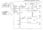
- FIG. 1is a block diagram showing the construction of a portable electronic device embodying the invention.
- FIG. 2is a flow chart showing the control procedure to be performed by a main CPU.
- FIG. 1shows a portable electronic device 1 of the invention, which has a USB connector 4 .
- a USB connector 5 of a personal computer 2 serving as a hostcan be connected to the USB connector 4 by a USB cable 11 , or an external power source 3 such as an a.c. adaptor can be connected to the USB connector 4 by a power source cable 12 .
- the USB connector 4has a pair of data terminals D+ and D ⁇ , a power source terminal V DD and a ground terminal GND.
- the portable electronic device 1comprises a USB controller 6 for executing predetermined data processing for conducting data communication with the personal computer 2 through the USB connector 4 , a main CPU 7 for executing predetermined device operation processing for various operations of the device including reproduction of data, and a memory 9 for storing the data downloaded from the personal computer 2 .
- the pair of data terminals D+ and D ⁇ of the USB connector 4are connected to a pair of data terminals D+ and D ⁇ provided on the USB controller 6 .
- the power source voltage obtained from the power source terminal V DD of the USB connector 4is adjusted to 3.3 V by a voltage regulator 8 and then supplied to the USB controller 6 and the main CPU 7 .
- the power source voltage to be supplied from the USB connector 5 of the personal computer 2is prescribed at 4.75 V to 5.25 V. Further when a hub is connected to the USB connector 4 in the case where the personal computer 2 , etc. provide a LAN, the power source voltage to be supplied from the hub is prescribed at 4.4 V to 5.25 V.
- the voltage to be supplied from the external power source 3is set at 4.0 V to 4.3 V. This makes it possible to discriminate between the sources of supply of power as will be described later and to avoid damage to other USB device even if the external power source 3 is connected to the device.
- a branch line 13Extending from the power source terminal V DD of the USB connector 4 is a branch line 13 which is connected to inverting means 10 and then to a USB connection detecting terminal USBin provided on the main CPU 7 .
- the branch line 13has connected thereto a pair of voltage dividing resistors R 1 and R 2 , and an intermediate point between the resistors is connected to a voltage detecting terminal Vdet provided on the main CPU 7 .
- FIG. 2shows the control procedure to be executed by the main CPU 7 .
- the personal computer 2 or the external power source 3is connected to the USB connector 4 of the portable electronic device 1 in step S 1 , this changes the voltage at the USB connection detecting terminal USBin from high to low, with the result that the main CPU 7 rises from sleep mode.
- step S 2the voltage value Vdet is retrieved from the voltage detecting terminal Vdet, and based on this voltage value Vdet, an inquiry is made in step S 3 as to whether the power source voltage is at least 4.4 V.
- the power source voltageis within the range of 4.4 V to 5.25 V, so that the inquiry is answered in the affirmative, followed by step S 4 . If the external power source 3 is connected to the USB connector 4 , on the other hand, the answer is negative since the power source voltage is in the range of 4.0 V to 4.3 V, followed by step S5.
- step S 4the main CPU 7 notifies the USB controller 6 of the connection of the personal computer 2 to the USB connector 4 , sets the controller 6 in communication mode and causes the controller 6 to start data communication processing with the personal computer 2 .
- step S 5the CPU 7 controls charging of the built-in secondary cell (not shown) as required, and executes device operation processing, such as data reproduction control, in response to the user's manipulation.
- the USB controller 6when the personal computer 2 is connected to the portable electronic device of the present invention by means of the USB connector 4 , the USB controller 6 is caused to execute only data communication processing assigned thereto, while when the external power source 3 is connected to the device, the main CPU 7 executes only device operation processing assigned thereto. In this way, the processing to be executed is distinctly divided in two. This assures the main CPU 7 of simplified processing at a higher speed.
- the main CPU 7entrusts the USB controller 6 with the processing, with the result that the USB controller 6 performs data communication with the computer 2 and stores the data downloaded therefrom via the USB connector 4 in the memory 9 .
- the main CPU 7commands the controller 6 to read the data from the memory 9 and receives the read data to execute device operation processing required for data reproduction. At this time, rapid processing is realized since the main CPU 7 takes the leadership of data processing.
- the common serial bus connectoris not limited to a USB connector in conformity with the USB standard but can be a connector compliant with other standard.
Landscapes
- Engineering & Computer Science (AREA)
- Theoretical Computer Science (AREA)
- General Engineering & Computer Science (AREA)
- Physics & Mathematics (AREA)
- General Physics & Mathematics (AREA)
- Computer Hardware Design (AREA)
- Power Sources (AREA)
- Information Transfer Systems (AREA)
- Studio Devices (AREA)
Abstract
Description
Claims (5)
Applications Claiming Priority (2)
| Application Number | Priority Date | Filing Date | Title |
|---|---|---|---|
| JPHEI.11-370327 | 1999-12-27 | ||
| JP37032799AJP3819658B2 (en) | 1999-12-27 | 1999-12-27 | Portable electronic devices with a common serial bus connector |
Publications (2)
| Publication Number | Publication Date |
|---|---|
| US20010005641A1 US20010005641A1 (en) | 2001-06-28 |
| US6904488B2true US6904488B2 (en) | 2005-06-07 |
Family
ID=18496629
Family Applications (1)
| Application Number | Title | Priority Date | Filing Date |
|---|---|---|---|
| US09/741,018Expired - LifetimeUS6904488B2 (en) | 1999-12-27 | 2000-12-21 | Portable electronic device comprising common serial bus connector |
Country Status (6)
| Country | Link |
|---|---|
| US (1) | US6904488B2 (en) |
| EP (1) | EP1139225B1 (en) |
| JP (1) | JP3819658B2 (en) |
| KR (1) | KR100666518B1 (en) |
| CN (1) | CN1175337C (en) |
| DE (1) | DE60002154T2 (en) |
Cited By (17)
| Publication number | Priority date | Publication date | Assignee | Title |
|---|---|---|---|---|
| US20020062456A1 (en)* | 2000-11-17 | 2002-05-23 | Stmicroelectronics S.A. | Device for automatically controlling a voltage applied to a data conductor in a serial link |
| US20020156949A1 (en)* | 2001-04-19 | 2002-10-24 | Kenji Kubo | Method of and device for detecting cable connection |
| US20040158131A1 (en)* | 2003-02-04 | 2004-08-12 | Wem Technology Inc. | Medical recording device carried on one's person |
| US20040235517A1 (en)* | 2003-05-21 | 2004-11-25 | Ying-Chien Lin | Wireless transmission apparatus |
| US20050020144A1 (en)* | 2003-07-23 | 2005-01-27 | Lunecki Daniel Kenneth | USB integrated module |
| US20060017840A1 (en)* | 2001-07-02 | 2006-01-26 | Fuji Photo Film Co., Ltd. | Digital camera and system thereof |
| US20070220499A1 (en)* | 2003-07-23 | 2007-09-20 | Silicon Laboratories Inc. | USB tool stick with multiple processors |
| US20070223161A1 (en)* | 2006-03-23 | 2007-09-27 | Sanyo Electric Co., Ltd. | Integrated Circuit and Signal Processing Apparatus Using the Same |
| US20080143185A1 (en)* | 2006-12-14 | 2008-06-19 | Ingles Roger H | System for Supplying Power for Peripheral Devices |
| US20090174991A1 (en)* | 2008-01-05 | 2009-07-09 | Mohhamad Mahdavi | Generation Power Cable for Computers |
| US20090228614A1 (en)* | 2008-03-10 | 2009-09-10 | Samsung Electronics Co., Ltd. | Method and apparatus for determining external connection device in mobile terminal |
| US20090307390A1 (en)* | 2008-06-04 | 2009-12-10 | Broadcom Corporation | Access of built-in peripheral components by internal and external bus pathways |
| US20100115147A1 (en)* | 2008-10-30 | 2010-05-06 | Samsung Electronics Co. Ltd. | Apparatus and method for controlling usb switching circuit in portable terminal |
| US20100287387A1 (en)* | 2009-05-08 | 2010-11-11 | Chen Johnny Hsiang-Yu | Docking station |
| US20120274155A1 (en)* | 2001-10-22 | 2012-11-01 | Apple Inc. | Power adapters for powering and/or charging peripheral devices |
| US20150049407A1 (en)* | 2013-08-14 | 2015-02-19 | Fujitsu Limited | Electronic device and voltage monitoring method |
| US20150137598A1 (en)* | 2013-11-21 | 2015-05-21 | Qualcomm Incorporated | Dynamic voltage adjust circuits and methods |
Families Citing this family (61)
| Publication number | Priority date | Publication date | Assignee | Title |
|---|---|---|---|---|
| JP3263675B2 (en)* | 1999-02-02 | 2002-03-04 | 三洋電機株式会社 | Electronic devices with common connectors |
| KR20030014912A (en)* | 2001-08-13 | 2003-02-20 | 엘지전자 주식회사 | Apparatus and Method for downloading a program in a multitude of mobile phone |
| WO2003036777A1 (en)* | 2001-10-22 | 2003-05-01 | Apple Computer, Inc. | Methods and apparatus for charging a battery in a peripheral device |
| JP3760839B2 (en)* | 2001-11-09 | 2006-03-29 | 株式会社日立製作所 | Communication terminal device |
| JP2003158561A (en) | 2001-11-21 | 2003-05-30 | Nec Corp | Mobile phone |
| US7987007B2 (en)* | 2002-03-18 | 2011-07-26 | Creative Technology Ltd | Memory module with audio playback mode |
| KR100474862B1 (en)* | 2002-04-25 | 2005-03-10 | 이스타랩(주) | the information equipment having a interface for communication cable and power feeding cable and the power feeding cable |
| KR100597734B1 (en) | 2002-06-25 | 2006-07-07 | 삼성전자주식회사 | Memory drive and control method |
| KR100476070B1 (en)* | 2002-08-12 | 2005-03-10 | 주식회사 인텔릭스 | Apparatus for interfacing between game terminal and computer |
| KR100920664B1 (en)* | 2002-11-19 | 2009-10-09 | 엘지전자 주식회사 | System driving apparatus and method in personal information terminal |
| JP3756882B2 (en) | 2003-02-20 | 2006-03-15 | 株式会社東芝 | Information processing apparatus and information processing method |
| JP4258264B2 (en)* | 2003-04-24 | 2009-04-30 | セイコーエプソン株式会社 | Information terminal device and POS terminal equipped with the same |
| JP2005070832A (en)* | 2003-08-22 | 2005-03-17 | Sharp Corp | Electronic device and interface device |
| KR101028245B1 (en)* | 2003-12-05 | 2011-04-11 | 엘지전자 주식회사 | Mobile communication terminal |
| US7529871B1 (en) | 2004-04-27 | 2009-05-05 | Apple Inc. | Communication between an accessory and a media player with multiple protocol versions |
| US7526588B1 (en) | 2004-04-27 | 2009-04-28 | Apple Inc. | Communication between an accessory and a media player using a protocol with multiple lingoes |
| US7529872B1 (en) | 2004-04-27 | 2009-05-05 | Apple Inc. | Communication between an accessory and a media player using a protocol with multiple lingoes |
| US7441058B1 (en) | 2006-09-11 | 2008-10-21 | Apple Inc. | Method and system for controlling an accessory having a tuner |
| US7634605B2 (en) | 2004-04-27 | 2009-12-15 | Apple Inc. | Method and system for transferring stored data between a media player and an accessory |
| US7826318B2 (en) | 2004-04-27 | 2010-11-02 | Apple Inc. | Method and system for allowing a media player to transfer digital audio to an accessory |
| US8117651B2 (en) | 2004-04-27 | 2012-02-14 | Apple Inc. | Method and system for authenticating an accessory |
| US7529870B1 (en) | 2004-04-27 | 2009-05-05 | Apple Inc. | Communication between an accessory and a media player with multiple lingoes |
| US7797471B2 (en) | 2004-04-27 | 2010-09-14 | Apple Inc. | Method and system for transferring album artwork between a media player and an accessory |
| US7673083B2 (en)* | 2004-04-27 | 2010-03-02 | Apple Inc. | Method and system for controlling video selection and playback in a portable media player |
| US7895378B2 (en) | 2004-04-27 | 2011-02-22 | Apple Inc. | Method and system for allowing a media player to transfer digital audio to an accessory |
| US7441062B2 (en) | 2004-04-27 | 2008-10-21 | Apple Inc. | Connector interface system for enabling data communication with a multi-communication device |
| US7581119B2 (en)* | 2004-07-18 | 2009-08-25 | Apple Inc. | Method and system for discovering a power source on a peripheral bus |
| US7541776B2 (en) | 2004-12-10 | 2009-06-02 | Apple Inc. | Method and system for operating a portable electronic device in a power-limited manner |
| US8588483B2 (en)* | 2004-12-21 | 2013-11-19 | Signaturelink, Inc. | System and method for providing a real-time, online biometric signature |
| US7525216B2 (en)* | 2005-01-07 | 2009-04-28 | Apple Inc. | Portable power source to provide power to an electronic device via an interface |
| US7823214B2 (en)* | 2005-01-07 | 2010-10-26 | Apple Inc. | Accessory authentication for electronic devices |
| EP1758029B1 (en)* | 2005-08-19 | 2009-09-30 | Stmicroelectronics SA | Secure USB peripheral |
| KR100753974B1 (en)* | 2006-01-05 | 2007-08-31 | 주식회사 텔레칩스 | Audio system |
| US7770036B2 (en)* | 2006-02-27 | 2010-08-03 | Apple Inc. | Power management in a portable media delivery system |
| US8086332B2 (en)* | 2006-02-27 | 2011-12-27 | Apple Inc. | Media delivery system with improved interaction |
| US7848527B2 (en) | 2006-02-27 | 2010-12-07 | Apple Inc. | Dynamic power management in a portable media delivery system |
| JP4669803B2 (en) | 2006-03-23 | 2011-04-13 | 三洋電機株式会社 | Integrated circuit and signal processing apparatus using the same |
| US8006019B2 (en) | 2006-05-22 | 2011-08-23 | Apple, Inc. | Method and system for transferring stored data between a media player and an accessory |
| US8073984B2 (en) | 2006-05-22 | 2011-12-06 | Apple Inc. | Communication protocol for use with portable electronic devices |
| CN100389602C (en)* | 2006-05-29 | 2008-05-21 | 中国移动通信集团公司 | Camera system and camera control method |
| US7415563B1 (en) | 2006-06-27 | 2008-08-19 | Apple Inc. | Method and system for allowing a media player to determine if it supports the capabilities of an accessory |
| US7558894B1 (en) | 2006-09-11 | 2009-07-07 | Apple Inc. | Method and system for controlling power provided to an accessory |
| US8001400B2 (en)* | 2006-12-01 | 2011-08-16 | Apple Inc. | Power consumption management for functional preservation in a battery-powered electronic device |
| EP2185992B1 (en)* | 2007-09-04 | 2013-07-17 | Apple Inc. | Smart dock for chaining accessories |
| US8047966B2 (en)* | 2008-02-29 | 2011-11-01 | Apple Inc. | Interfacing portable media devices and sports equipment |
| JP5058083B2 (en)* | 2008-06-25 | 2012-10-24 | シャープ株式会社 | Interface device |
| US8238811B2 (en) | 2008-09-08 | 2012-08-07 | Apple Inc. | Cross-transport authentication |
| US8208853B2 (en) | 2008-09-08 | 2012-06-26 | Apple Inc. | Accessory device authentication |
| US8452903B2 (en) | 2009-03-16 | 2013-05-28 | Apple Inc. | Mobile computing device capabilities for accessories |
| US8909803B2 (en) | 2009-03-16 | 2014-12-09 | Apple Inc. | Accessory identification for mobile computing devices |
| US8891803B2 (en)* | 2009-06-23 | 2014-11-18 | Flextronics Ap, Llc | Notebook power supply with integrated subwoofer |
| JP5321343B2 (en)* | 2009-08-13 | 2013-10-23 | 富士通セミコンダクター株式会社 | Connector detection circuit |
| US8626932B2 (en)* | 2009-09-01 | 2014-01-07 | Apple Inc. | Device-dependent selection between modes for asymmetric serial protocols |
| JP4944213B2 (en)* | 2010-01-04 | 2012-05-30 | 株式会社バッファロー | Main device, external device, and communication system |
| US20120076371A1 (en)* | 2010-09-23 | 2012-03-29 | Siemens Aktiengesellschaft | Phantom Identification |
| JP5367030B2 (en)* | 2011-08-10 | 2013-12-11 | シャープ株式会社 | Electronic equipment and electronic equipment system |
| JP2013122698A (en)* | 2011-12-12 | 2013-06-20 | Hosiden Corp | Audio equipment |
| US9306879B2 (en) | 2012-06-08 | 2016-04-05 | Apple Inc. | Message-based identification of an electronic device |
| CN103577358B (en)* | 2012-08-07 | 2016-12-21 | 瑞萨电子(中国)有限公司 | A kind of serial bus data analyser, analysis system and the method for analysis |
| CN105988966B (en)* | 2014-12-22 | 2019-10-11 | 株式会社东芝 | Electronic devices and their working methods |
| CN110175142B (en)* | 2019-04-18 | 2021-03-23 | 深圳市普威技术有限公司 | Interface expansion circuit and device |
Citations (6)
| Publication number | Priority date | Publication date | Assignee | Title |
|---|---|---|---|---|
| WO1996013802A1 (en) | 1994-10-31 | 1996-05-09 | Motorola, Inc. | A peripheral card having independent functionality and method used therewith |
| US5928336A (en) | 1996-07-15 | 1999-07-27 | International Business Machines Corporation | PC card and peripheral device |
| US6058441A (en)* | 1998-02-19 | 2000-05-02 | Shu; Han | USB multi-function connecting device |
| US6178514B1 (en)* | 1998-07-31 | 2001-01-23 | Bradley C. Wood | Method and apparatus for connecting a device to a bus carrying power and a signal |
| US6516418B1 (en)* | 1998-07-23 | 2003-02-04 | Samsung Electronics Co., Ltd. | Portable computer having universal serial bus ports controlled power supply and a method of the same |
| US6697892B1 (en)* | 1999-07-08 | 2004-02-24 | Intel Corporation | Port expansion system |
- 1999
- 1999-12-27JPJP37032799Apatent/JP3819658B2/ennot_activeExpired - Fee Related
- 2000
- 2000-12-19EPEP00127838Apatent/EP1139225B1/ennot_activeExpired - Lifetime
- 2000-12-19DEDE60002154Tpatent/DE60002154T2/ennot_activeExpired - Lifetime
- 2000-12-21USUS09/741,018patent/US6904488B2/ennot_activeExpired - Lifetime
- 2000-12-27CNCNB001380451Apatent/CN1175337C/ennot_activeExpired - Lifetime
- 2000-12-27KRKR1020000082562Apatent/KR100666518B1/ennot_activeExpired - Lifetime
Patent Citations (6)
| Publication number | Priority date | Publication date | Assignee | Title |
|---|---|---|---|---|
| WO1996013802A1 (en) | 1994-10-31 | 1996-05-09 | Motorola, Inc. | A peripheral card having independent functionality and method used therewith |
| US5928336A (en) | 1996-07-15 | 1999-07-27 | International Business Machines Corporation | PC card and peripheral device |
| US6058441A (en)* | 1998-02-19 | 2000-05-02 | Shu; Han | USB multi-function connecting device |
| US6516418B1 (en)* | 1998-07-23 | 2003-02-04 | Samsung Electronics Co., Ltd. | Portable computer having universal serial bus ports controlled power supply and a method of the same |
| US6178514B1 (en)* | 1998-07-31 | 2001-01-23 | Bradley C. Wood | Method and apparatus for connecting a device to a bus carrying power and a signal |
| US6697892B1 (en)* | 1999-07-08 | 2004-02-24 | Intel Corporation | Port expansion system |
Non-Patent Citations (3)
| Title |
|---|
| "Universal Serial Bus Specification" Revision 1.0, pp. 111-136, Jan. 15, 1996.* |
| Lynn, K. "Universal serial bus (USB) power management" Nov. 4-6, 1998, Wescon/97 Conference Proceedings, pp. 434-441.* |
| Lynn, K. "Universal serial bus (USB) power management" Sep. 15-17, 1998, Wescon/98 Conference Proceedings, pp. 194-201.* |
Cited By (34)
| Publication number | Priority date | Publication date | Assignee | Title |
|---|---|---|---|---|
| US7000123B2 (en)* | 2000-11-17 | 2006-02-14 | Stmicroelectronics Sa | Device for automatically controlling a voltage applied to a data conductor in a serial link |
| US20020062456A1 (en)* | 2000-11-17 | 2002-05-23 | Stmicroelectronics S.A. | Device for automatically controlling a voltage applied to a data conductor in a serial link |
| US20110055615A1 (en)* | 2001-04-19 | 2011-03-03 | Renesas Technology Corp. | Method of and device for detecting cable connection |
| US7797557B2 (en) | 2001-04-19 | 2010-09-14 | Mitsubishi Electric System Lsi Design Corporation | Method of and device for detecting a cable connection with a root hub |
| US7082545B2 (en)* | 2001-04-19 | 2006-07-25 | Renesas Technology Corp. | Method of and device for detecting cable connection |
| US20060248365A1 (en)* | 2001-04-19 | 2006-11-02 | Renesas Technology Corp. | Method of and device for detecting cable connection |
| US20020156949A1 (en)* | 2001-04-19 | 2002-10-24 | Kenji Kubo | Method of and device for detecting cable connection |
| US20070260902A1 (en)* | 2001-04-19 | 2007-11-08 | Renesas Technology Corp. | Method of and device for detecting cable connection |
| US7334151B2 (en) | 2001-04-19 | 2008-02-19 | Renesas Technology Corp. | Method of and device for detecting cable connection using an oscillation circuit and a counter |
| US20060017840A1 (en)* | 2001-07-02 | 2006-01-26 | Fuji Photo Film Co., Ltd. | Digital camera and system thereof |
| US10312704B2 (en) | 2001-10-22 | 2019-06-04 | Apple Inc. | Power adapters for powering and/or charging peripheral devices |
| US20120274155A1 (en)* | 2001-10-22 | 2012-11-01 | Apple Inc. | Power adapters for powering and/or charging peripheral devices |
| US20040158131A1 (en)* | 2003-02-04 | 2004-08-12 | Wem Technology Inc. | Medical recording device carried on one's person |
| US20040235517A1 (en)* | 2003-05-21 | 2004-11-25 | Ying-Chien Lin | Wireless transmission apparatus |
| US7050840B2 (en)* | 2003-05-21 | 2006-05-23 | Admtek Incorporated | Wireless transmission apparatus |
| US7502883B2 (en)* | 2003-07-23 | 2009-03-10 | Silicon Labs Cp, Inc. | USB integrated module |
| US20070220499A1 (en)* | 2003-07-23 | 2007-09-20 | Silicon Laboratories Inc. | USB tool stick with multiple processors |
| US20050020144A1 (en)* | 2003-07-23 | 2005-01-27 | Lunecki Daniel Kenneth | USB integrated module |
| US7757104B2 (en)* | 2006-03-23 | 2010-07-13 | Sanyo Electric Co., Ltd. | Integrated circuit and signal processing apparatus using the same |
| US20070223161A1 (en)* | 2006-03-23 | 2007-09-27 | Sanyo Electric Co., Ltd. | Integrated Circuit and Signal Processing Apparatus Using the Same |
| US7644203B2 (en) | 2006-12-14 | 2010-01-05 | Samsung Electronics Co., Ltd. | System for supplying power for peripheral devices |
| US20080143185A1 (en)* | 2006-12-14 | 2008-06-19 | Ingles Roger H | System for Supplying Power for Peripheral Devices |
| US20090174991A1 (en)* | 2008-01-05 | 2009-07-09 | Mohhamad Mahdavi | Generation Power Cable for Computers |
| US8402175B2 (en)* | 2008-03-10 | 2013-03-19 | Samsung Electronics Co., Ltd. | Method and apparatus for determining external connection device in mobile terminal |
| US20090228614A1 (en)* | 2008-03-10 | 2009-09-10 | Samsung Electronics Co., Ltd. | Method and apparatus for determining external connection device in mobile terminal |
| US20090307390A1 (en)* | 2008-06-04 | 2009-12-10 | Broadcom Corporation | Access of built-in peripheral components by internal and external bus pathways |
| US8412861B2 (en)* | 2008-10-30 | 2013-04-02 | Samsung Electronics Co., Ltd. | Apparatus and method for controlling USB switching circuit in portable terminal |
| US20100115147A1 (en)* | 2008-10-30 | 2010-05-06 | Samsung Electronics Co. Ltd. | Apparatus and method for controlling usb switching circuit in portable terminal |
| US8719461B2 (en) | 2008-10-30 | 2014-05-06 | Samsung Electronics Co., Ltd. | Apparatus and method for controlling USB switching circuit in portable terminal |
| US20100287387A1 (en)* | 2009-05-08 | 2010-11-11 | Chen Johnny Hsiang-Yu | Docking station |
| US20150049407A1 (en)* | 2013-08-14 | 2015-02-19 | Fujitsu Limited | Electronic device and voltage monitoring method |
| US9490625B2 (en)* | 2013-08-14 | 2016-11-08 | Fujitsu Limited | Electronic device and voltage monitoring method |
| US20150137598A1 (en)* | 2013-11-21 | 2015-05-21 | Qualcomm Incorporated | Dynamic voltage adjust circuits and methods |
| US9673651B2 (en)* | 2013-11-21 | 2017-06-06 | Qualcomm Incorporated | Dynamic voltage adjust circuits and methods |
Also Published As
| Publication number | Publication date |
|---|---|
| DE60002154T2 (en) | 2004-03-25 |
| EP1139225A1 (en) | 2001-10-04 |
| CN1175337C (en) | 2004-11-10 |
| JP3819658B2 (en) | 2006-09-13 |
| KR100666518B1 (en) | 2007-01-11 |
| EP1139225B1 (en) | 2003-04-16 |
| CN1308262A (en) | 2001-08-15 |
| US20010005641A1 (en) | 2001-06-28 |
| KR20010062726A (en) | 2001-07-07 |
| JP2001184146A (en) | 2001-07-06 |
| DE60002154D1 (en) | 2003-05-22 |
Similar Documents
| Publication | Publication Date | Title |
|---|---|---|
| US6904488B2 (en) | Portable electronic device comprising common serial bus connector | |
| KR101494900B1 (en) | A portable terminal having a charging function through charging device identification and a method | |
| EP1113355B1 (en) | Portable electronic device | |
| US8694809B2 (en) | Dedicated power supply apparatus, terminal, power supply system, and power supply method | |
| JP4806076B2 (en) | Charging cable with USB-like connector | |
| US8438407B2 (en) | Electronic device that operates in two modes based on connection to power supply and command information | |
| US20200004309A1 (en) | Electronic device | |
| EP3771987A1 (en) | Electronic device for preventing damage of usb device and operating method thereof | |
| US11181958B2 (en) | Electronic device with power source control ciruitry for determining a current | |
| US20070035276A1 (en) | Charging system for charging accumulator means in an electronic device, and a charging apparatus and an electronic device for the system | |
| KR20040074491A (en) | Hot plug signal generation apparatus and method | |
| JP2019121110A (en) | Electronic apparatus, control method and program | |
| TW202139558A (en) | USB charging circuit and method, chip and charger | |
| EP1700463B1 (en) | Accessory functions | |
| CN116131372A (en) | Charging circuit and system, wearable device, charging method for wearable device | |
| KR100700532B1 (en) | How to recognize the connector on the universal serial bus port and the universal serial bus adapter | |
| KR20050040549A (en) | Mobile station for cognizing the external apparatus using the universal serial bus port | |
| US7069364B2 (en) | Automatic status assignment logic circuit apparatus for bay devices | |
| CN113382113A (en) | Intelligent mobile communication terminal storage equipment activating device | |
| KR20060100054A (en) | Wireless communication terminal with charging function through charging cable detection and its method |
Legal Events
| Date | Code | Title | Description |
|---|---|---|---|
| AS | Assignment | Owner name:SANYO ELECTRIC CO., LTD., JAPAN Free format text:ASSIGNMENT OF ASSIGNORS INTEREST;ASSIGNORS:MATSUMOTO, KATSUYUKI;YOSHIDA, MASANAO;REEL/FRAME:011402/0699 Effective date:20001117 Owner name:SANYO TECHNOSOUND CO., LTD., JAPAN Free format text:ASSIGNMENT OF ASSIGNORS INTEREST;ASSIGNORS:MATSUMOTO, KATSUYUKI;YOSHIDA, MASANAO;REEL/FRAME:011402/0699 Effective date:20001117 | |
| STCF | Information on status: patent grant | Free format text:PATENTED CASE | |
| FEPP | Fee payment procedure | Free format text:PAYOR NUMBER ASSIGNED (ORIGINAL EVENT CODE: ASPN); ENTITY STATUS OF PATENT OWNER: LARGE ENTITY | |
| FPAY | Fee payment | Year of fee payment:4 | |
| FPAY | Fee payment | Year of fee payment:8 | |
| AS | Assignment | Owner name:XACTI CORPORATION, JAPAN Free format text:ASSIGNMENT OF ASSIGNORS INTEREST;ASSIGNOR:SANYO ELECTRIC CO., LTD.;REEL/FRAME:032467/0095 Effective date:20140305 Owner name:SANYO ELECTRIC CO., LTD., JAPAN Free format text:MERGER;ASSIGNOR:SANYO TECHNOSOUND CO., LTD.;REEL/FRAME:032462/0155 Effective date:20060105 | |
| AS | Assignment | Owner name:XACTI CORPORATION, JAPAN Free format text:CORRECTIVE ASSIGNMENT TO CORRECT THE TO CORRECT THE INCORRECT PATENT NUMBER 13/446,454, AND REPLACE WITH 13/466,454 PREVIOUSLY RECORDED ON REEL 032467 FRAME 0095. ASSIGNOR(S) HEREBY CONFIRMS THE ASSIGNMENT OF ASSIGNORS INTEREST;ASSIGNOR:SANYO ELECTRIC CO., LTD.;REEL/FRAME:032601/0646 Effective date:20140305 | |
| FPAY | Fee payment | Year of fee payment:12 |