US6904363B2 - System for local monitoring - Google Patents
System for local monitoringDownload PDFInfo
- Publication number
- US6904363B2 US6904363B2US10/223,603US22360302AUS6904363B2US 6904363 B2US6904363 B2US 6904363B2US 22360302 AUS22360302 AUS 22360302AUS 6904363 B2US6904363 B2US 6904363B2
- Authority
- US
- United States
- Prior art keywords
- client
- flag
- response
- notification point
- encompassing
- Prior art date
- Legal status (The legal status is an assumption and is not a legal conclusion. Google has not performed a legal analysis and makes no representation as to the accuracy of the status listed.)
- Expired - Lifetime, expires
Links
Images


Classifications
- G—PHYSICS
- G08—SIGNALLING
- G08G—TRAFFIC CONTROL SYSTEMS
- G08G1/00—Traffic control systems for road vehicles
- G08G1/20—Monitoring the location of vehicles belonging to a group, e.g. fleet of vehicles, countable or determined number of vehicles
Definitions
- the present inventionrelates generally to monitoring, in particular the invention relates to monitoring of position.
- a wide variety of tasksare performed using vehicles. These tasks often include pickup and delivery of persons and/or goods. It is sometimes desirable to have a record of the time and place of the performance of these tasks.
- An example of a conventional methodis a simple handwritten log kept by drivers of the vehicle, such as those commonly used by truck drivers.
- the ability to track a vehiclemay help assist a coordinator to send assistance to a disabled vehicle.
- various positioning systemswhich have been used for determining the location of a vehicle. These include LORAN systems and Global Positioning Systems (GPS). These systems rely on externally transmitted radio frequency signals to calculate the location of a receiving antenna mounted on the vehicle. In LORAN systems, this calculation is based on the time difference in signals received from multiple transmitters. Because the latitude and longitude of the transmitters are known, the distance from two or more transmitters can be calculated from the time lag between the reception of the plurality of signals. The resulting calculation can determine the latitude and longitude of the receiving antenna to within approximately plus or minus 20 feet.
- the transmittersare positioned on orbiting satellites. Time and location information of the satellites plus the Doppler shift of the radio frequency signal received from the satellite is used to calculate the location of the receiver. GPS systems can determine location with even greater accuracy than LORAN systems.
- the existing positioning systemsare not particularly useful for tracking the location of a vehicle during predetermined events. This is because they are generally designed for the purpose of informing an operator of the vehicle of his current location.
- One embodiment of the inventionrelates to a method of monitoring.
- the methodincludes receiving position information related to a notification point and determining a position of a mobile client by the mobile client.
- the methodalso includes comparing the position with an area encompassing the notification point and transmitting a message in response to the position being within the area encompassing the notification point.
- Another embodiment of the present inventionpertains to a method of locally monitoring position.
- the methodincludes receiving a plurality of waypoints and determining a position of a client by the client.
- the methodalso includes comparing the position of the client to a selected waypoint of the plurality of waypoints and transmitting a message in response to the position of the client being within a first circle encompassing the selected waypoint.
- Yet another embodiment of the inventionrelates to a method of locally monitoring a client.
- the methodincludes receiving a plurality of waypoints and determining a position of the client.
- the methodalso includes comparing the position of the client to a selected waypoint of the plurality of waypoints, and transmitting a message in response to the position of the client being within a first circle encompassing the selected waypoint.
- the systemincludes a client, a proximity module configured to execute on the client, a global positioning system (GPS) module configured to interface with the proximity module, and a host system.
- the host systemis configured to transmit a selected location or a plurality of locations to the proximity module.
- the proximity moduleis configured to receive the selected location or plurality of locations and to determine a position of the client from the GPS module.
- the proximity moduleis also configured to compare the position of the client with the selected location or a selected location within the plurality of locations and to transmit a message to the host system in response to the position of the client being within an area encompassing the selected location.
- the apparatusincludes means for receiving position information related to a notification point and means for determining a position of a mobile client by the mobile client.
- the apparatusalso includes means for comparing the position with an area encompassing the notification point and means for transmitting a message in response to the position being within the area encompassing the notification point.
- FIG. 1illustrates an embodiment of the present invention
- FIG. 2illustrates an embodiment of a system in accordance with an embodiment of the present invention
- FIG. 3illustrates a block diagram of an architecture of a host system shown in FIG. 2 in accordance with an embodiment of the present invention
- FIG. 4illustrates a format of a configuration message transmitted from the host proximity module to the proximity module of the client in accordance with an embodiment of the invention
- FIG. 5illustrates a block diagram of an architecture of a client system shown in FIG. 2 in accordance with an embodiment of the present invention.
- FIG. 6illustrates a flow diagram for a method for the proximity module shown in FIG. 1 in accordance with an embodiment of the present invention.
- a proximity moduleis configured to determine the position of a mobile client in relation to a predefined location. More particularly, the proximity module may receive a configuration message when activated by a host communication system.
- the configuration messagecomprises positional information (e.g., latitude/longitude coordinates, destination radius, tolerance radius, etc.) relating to at least one predefined locations (e.g., notifications points, waypoints, destinations, etc.).
- the proximity modulemay also be configured to obtain position information of the mobile client from a GPS module. The proximity module may then calculate the position of the mobile client in relation to the predefined locations. For example, the proximity module may use the received position information, i.e., latitude-longitude, and determine whether the mobile client is within a destination circles formed around the predefined locations.
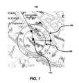
- FIG. 1An embodiment of the present invention is illustrated in FIG. 1 .
- the map 100includes a pre-defined location 110 .
- pre-defined location 110Although only one predefined location 110 is shown in FIG. 1 , multiple predefined locations are also contemplated in other embodiment of the present invention and are within the scope of the present invention.
- the predefined location 110is transmitted to a vehicle in a latitude/longitude format.
- a destination circle 120may be formed around the predefined location 110 with the predefined location 110 as the center of the destination circle.
- the radius of the destination circle 120may be user-specified or set by a default setting.
- a tolerance circle 130may also be formed around and centered on the predefined location 110 . In one embodiment of the present invention, the radius of the tolerance circle 130 is larger than the radius of the destination circle 120 .
- the radius of the tolerance circlemay also be user-specified or set by a default setting.
- the predefined location 110 , the radii of the destination circle 120 and the tolerance circle 130may be forwarded to the mobile client in the configuration message.
- the mobile clientwhen a mobile client enters the destination circle 120 , the mobile client sends a message to a host. While the mobile client is within the destination circle 120 , the mobile client transmits a second message notifying the host communication system that the mobile client is still within the destination circle 120 . When mobile client leaves a tolerance circle 130 , the mobile client transmits a third message notifying the host communication system that the mobile client has left the predefined location 110 .
- a user of the host communication systemmay become aware of when a mobile client enters the proximity of a selected location.
- the usermay also be informed of the length of time the mobile client spends in the selected location.
- the user of the host systemmay be informed when the mobile client leaves the selected location.
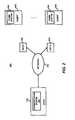
- FIG. 2illustrates an exemplary system 200 where an embodiment of the invention may be practiced.
- FIG. 2illustrates an exemplary embodiment of the system 200
- FIG. 2represents a generalized schematic illustration of the system 200 and that other components may be added or existing components may be removed or modified without departing from the spirit or scope of the present invention.
- the system 200includes a host 210 , a network 220 , and clients 230 .
- the host 210may be configured to monitor, track, and collect information about the clients 230 over the network 220 .
- the host 210may also be configured to provide a communication system 240 to provide a mechanism for the monitoring, tracking and collection of information as well as provide a two-way communication channel between the host 210 and the clients 230 .
- the host 210may be implemented by electronic devices such as personal computers, workstations, servers, and other similar devices.
- An example of the communication system 240may be the AETHER SYSTEMS MobileMAX2TM. It should be readily apparent to those skilled in the art that other communication software that provide for similar functionality of the communication system 240 may be implemented by the host 210 .
- the host 210may be further configured to interface with the network 220 .
- the network 220may be configured to provide a communication channel between the host 210 and the clients 230 .
- the network 220may be implemented as a private network, a public network (e.g., the Internet, public switched telephone network, etc.) or a combination thereof.
- the host 210may interface with the network 220 over wired (e.g., modem, digital subscriber lines, Internet, etc.) or wireless (e.g., WAP, IEEE 802.11, etc.,) interfaces.
- the network 220may also be configured to interface with transceivers 250 (e.g., antennas, satellites, etc.)
- the transceivers 250(labeled RX/TX in FIG. 2 ) are configured to broadcast signals to and receive signals from the clients 130 .
- the transceivers 250are also configured to provide coverage over a wide geographic area.
- the clients 230may be mobile units that are to be monitored by the host 210 .
- the clients 230may comprise a complementary transceiver (not shown) to interface with transceivers 250 in order to provide a communication link to the host 210 .
- the clients 230may be configured to execute a client version of the communication system 240 in order to provide the functionality of monitoring, tracking, data collection, and communication services. Examples of clients 230 may be wireless telephones, personal digital assistants, laptops, automobiles, trucks, airplanes, boats, etc.
- the communication system 240may include a proximity module (not shown).
- the proximity moduleonce activated, may be configured to provide an indication of when client 230 nears a selected notification point (e.g., a location point, waypoint, destination, etc.).
- the proximity modulemay also be configured to provide a frequent indication of how long the client 230 is near the notification point and an indication of when the client 230 leaves the proximity of the notification point.
- FIG. 3illustrates a block diagram of an architecture 300 of communication system 240 shown in FIG. 2 executing on host 210 in accordance with an embodiment of the present invention.
- the architecture 300may include the communication system interface 310 , a monitor module 320 , a host proximity module 330 , and a summary 340 .
- FIG. 3illustrates one embodiment of the architecture 300 , it should be readily apparent to those of ordinary skill in the art that FIG. 3 represents a generalized schematic illustration of the architecture 300 and that other components may be added or existing components may be removed or modified without departing from the spirit or scope of the present invention.
- the components of architecture 300may be implemented in hardware, software or combinations thereof.
- the communication system interface 310may be configured to provide a communication channel to the communication system 240 (shown in FIG. 2 ).
- the communication system interface 310may provide a mechanism where data and/or commands are passed between the communication system 240 and the monitor module 320 .
- the communication system 240may be implemented as a hardware interface (e.g. bus interface), software interface (e.g., an application program interface) or a combination thereof.
- the monitor module 320may be configured to provide an interface for the user to activate the monitoring, tracking and/or data collection functions when invoked by action from a user of the communication system 240 .
- the monitor module 320may collect information such as mileage, state crossings, idle time, location, etc.
- the collected informationmay be stored in the summary 340 .
- the usermay then process the collected information to extract relevant information such as mapping of the location of clients 130 , driver performance summaries, fleet summaries, etc.
- the monitor module 320may also be configured to display menus, dialog boxes, screen interfaces or combinations thereof, i.e., the graphical user interface, to enable a user to select the types of information to collect from the client 230 . From the monitor module 320 , the user may invoke the host proximity module 330 .
- the host proximity module 330may be configured to provide a mechanism to select a plurality of notification points for a particular client. More particularly, the host proximity module 330 may provide a graphical user interface for a user to invoke the host proximity module 330 .
- the graphical user interfacemay be a mechanism for the user to create (or enter) notification points (e.g., location points, waypoints, destination points, etc.) for a selected client. Each notification point may be specified by latitude/longitude, by referencing to database of location or map, or other similar methods of information transfer.
- a radius for a destination circlee.g., destination circle 120 in FIG. 1
- a tolerance circlee.g., tolerance circle 130 in FIG. 1
- the destination circlemay encompass and be centered on the respective notification point.
- the proximity module on the clientmay be configured to transmit a message (e.g., message type 1 ) notifying the host that the client is near to the notification point and to set an entrance flag.
- the proximity modulemay be configured to transmit a message (e.g., a message type 2 ) at a specified frequency to the host system.
- a messagee.g., a message type 2
- the frequencymay be set by a user at the host system and is transmitted along with the information relating to the notification points.
- the tolerance circlemay also encompass and be centered on the respective notification point.
- the host system 210may receive a message (e.g., message type 3 ) indicating that the client has left the vicinity of the notification point from the proximity module of the client.
- FIG. 4illustrates a format of a message 400 transmitted from the host proximity module to the proximity module of the client in accordance with an embodiment of the invention.
- the message 400includes a point identification field 405 , a latitude field 410 , a longitude field 415 , a destination radius field 420 , a tolerance radius field 425 , and a frequency field 430 .
- FIG. 4represents a generalized schematic illustration of the message 400 that other fields may be added or existing fields may be removed or modified without departing from the spirit or scope of the present invention.
- the point identification field 405may be configured to provide a label for a selected notification point.
- the values in the point identification field 405may range from 1 to 65535. However, the values may range to larger or smaller values depending on the needs of a particular user.
- a value in the latitude field 410may be configured to indicate the latitude coordinate of a selected notification point.
- a value in the longitude field 415may be configured to indicate the longitude coordinate of a selected notification point.
- a value in the destination radius field 420indicates the length (e.g., in miles, kilometers, etc.) of the circular area encompassing and centered on the selected notification point.
- a value in the tolerance radius field 425may indicate the length (e.g., miles, kilometers, etc.) of the circular area encompassing and centered on the selected notification point. It should be noted that the value of the tolerance radius field 425 is larger than the value of the destination radius field 420 .
- a value in the frequency 430may indicate that the frequency of transmission of the message that indicates the client 230 is within the destination circle.
- the summary module 340may be configured to provide a storage area for information received by the host system 210 .
- the summary module 340may be implemented as a relational database, a file, or other similar data structure.
- FIG. 5illustrates a block diagram of an architecture 500 of communication system 240 shown in FIG. 2 executing on client 230 in accordance with an embodiment of the present invention.
- the architecture 500may include the communication system interface 510 , a monitor module 520 , a client interface 530 , a proximity module 540 , and a global position system (GPS) module 550 .
- GPSglobal position system
- FIG. 5illustrates an embodiment of the architecture 500 , it should be readily apparent to those of ordinary skill in the art that FIG. 5 represents a generalized schematic illustration of the architecture 500 and that other components may be added or existing components may be removed or modified without departing from the spirit or scope of the present invention.
- the components of architecture 500may be implemented in hardware, software or combinations thereof.
- the communication system interface 510may be configured to provide an interface for passing commands and/or data between the monitor module 520 and the communication system 240 (shown in FIG. 2 ).
- the communication system interface 510may be implemented as an application program interface, a pipe, a function call, etc.
- the monitor module 520may be configured to collect information to transmit to the host system 210 through the communication system interface 510 .
- the monitor module 520may be further configured to have a client interface 530 .
- the client interface 530may provide a communication conduit in order to query (or request) the requested information.
- the client 230is a truck
- the requested informationmay be mileage, gasoline consumed, idling time, etc.
- the client interface 530may be implemented with a J1587 (also known as J1708) bus.
- the monitor module 520may be further configured to interface with the proximity module 540 .
- the proximity module 520may be configured to activate in response to a command transmitted from the host system 210 (shown in FIG. 2 ).
- the proximity module 520may also be configured to interface with the GPS module 550 , either indirectly through the monitor module 520 or directly.
- the GPS module 550may be configured to provide latitude/longitude position of the client 230 through the GPS satellites.
- the proximity module 520may be configured to determine to alert the host system 210 when the client 230 nears the notification points by processing the received latitude-longitude of the current position of the client 230 .
- the proximity module 520may also be configured to indicate the length of time the client spends near the notification points as well when the client leaves the tolerance circle.
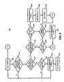
- FIG. 6illustrates a flow diagram for a method 600 for the proximity module 540 shown in FIG. 5 in accordance with an embodiment of the present invention. It should be readily apparent to those of ordinary skill in the art that the method 600 depicted in FIG. 6 represents a generalized illustration and that other steps may be added or existing steps may be removed or modified without departing from the spirit or scope of the present invention.
- the proximity module 540may be configured to be an idle state, in step 605 .
- the proximity modulemay be configured to receive positional information (e.g., latitude/longitude) of the current position of the client 230 , in step 610 .
- the proximity module 540may be configured to compare the received positional information with the area of the tolerance circle of a selected notification point, in step 615 . If the comparison determines that the current position of the client is not within the area of the tolerance circle, the proximity module 540 may be configured to determine the state of a flag, in step 620 . Otherwise, if the comparison determines that the current position of the client 230 is within the area of the tolerance circle, the proximity module 540 moves to the processing of step 635 , which is discussed below.
- the proximity module 540returns to the idle state of step 605 .
- the entrance flagis an indicator of whether the client 230 has previously entered into the destination circle of the selected notification point. Otherwise, if the state of the entrance flag is set, the proximity module 540 may be configured to send a message to the host system 210 , in step 625 . The message may indicate to the host system 210 that the client 230 has left the vicinity of the selected notification point. Then, the proximity module 540 may be configured to reset the state of the entrance flag, in step 630 . Subsequently, the proximity module 540 may be configured to return to the idle state of step 605 .
- the proximity module 540may be configured to determine whether the current position of the client is within the destination circle. If the client is not within the destination circle, the proximity module 540 may be configured to determine the state of the entrance flag, in step 640 . If the state of the entrance flag is set, the proximity module 540 may be configured to move to the processing of step 650 , which is described below. Otherwise, if the state of the entrance flag is unset, the proximity module 540 may be configured to return to the idle state of step 605 .
- the proximity module 540may be configured to transmit yet another message to the host system, in step 660 .
- This third messageindicates to the host system 210 that the client 230 has entered the vicinity of the selected notification point, where the vicinity may be the area encompassing and centered on the selected notification point by the destination circle radius.
- the proximity module 540may be configured to set the state of the entrance flag.
- the proximity module 540may also be configured to set the timer to the time indicated by the frequency field 430 of message 400 (shown in FIG. 4 ), in step 670 . Subsequently, the proximity module 540 may be configured to return to the idle state of 605 .
- a computer programmay implement the modes of operations of the proximity module as described herein above.
- the computer programcan exist in a variety of forms both active and inactive.
- the computer program and objectscan exist as software comprised of program instructions or statements in source code, object code, executable code or other formats; firmware program(s); or hardware description language (HDL) files.
- Any of the abovecan be embodied on a computer readable medium, which include storage devices and signals, in compressed or uncompressed form.
- Exemplary computer readable storage devicesinclude conventional computer system RAM (random access memory), ROM (read only memory), EPROM (erasable, programmable ROM), EEPROM (electrically erasable, programmable ROM), and magnetic or optical disks or tapes.
- Exemplary computer readable signalsare signals that a computer system hosting or running the computer program can be configured to access, including signals downloaded through the Internet or other networks. Concrete examples of the foregoing include distribution of executable software program(s) of the computer program on a CD ROM or via Internet download. In a sense, the Internet itself, as an abstract entity, is a computer readable medium.
Landscapes
- Physics & Mathematics (AREA)
- General Physics & Mathematics (AREA)
- Mobile Radio Communication Systems (AREA)
Abstract
Description
Claims (27)
Priority Applications (2)
| Application Number | Priority Date | Filing Date | Title |
|---|---|---|---|
| US10/223,603US6904363B2 (en) | 2002-08-20 | 2002-08-20 | System for local monitoring |
| US11/141,866US7043365B2 (en) | 2002-08-20 | 2005-05-31 | System for local monitoring |
Applications Claiming Priority (1)
| Application Number | Priority Date | Filing Date | Title |
|---|---|---|---|
| US10/223,603US6904363B2 (en) | 2002-08-20 | 2002-08-20 | System for local monitoring |
Related Child Applications (1)
| Application Number | Title | Priority Date | Filing Date |
|---|---|---|---|
| US11/141,866ContinuationUS7043365B2 (en) | 2002-08-20 | 2005-05-31 | System for local monitoring |
Publications (2)
| Publication Number | Publication Date |
|---|---|
| US20040039526A1 US20040039526A1 (en) | 2004-02-26 |
| US6904363B2true US6904363B2 (en) | 2005-06-07 |
Family
ID=31886671
Family Applications (2)
| Application Number | Title | Priority Date | Filing Date |
|---|---|---|---|
| US10/223,603Expired - LifetimeUS6904363B2 (en) | 2002-08-20 | 2002-08-20 | System for local monitoring |
| US11/141,866Expired - LifetimeUS7043365B2 (en) | 2002-08-20 | 2005-05-31 | System for local monitoring |
Family Applications After (1)
| Application Number | Title | Priority Date | Filing Date |
|---|---|---|---|
| US11/141,866Expired - LifetimeUS7043365B2 (en) | 2002-08-20 | 2005-05-31 | System for local monitoring |
Country Status (1)
| Country | Link |
|---|---|
| US (2) | US6904363B2 (en) |
Cited By (14)
| Publication number | Priority date | Publication date | Assignee | Title |
|---|---|---|---|---|
| US20060015513A1 (en)* | 2004-07-13 | 2006-01-19 | Nokia Corporation | System, network entities and computer programs for configuration management of a dynamic host configuration protocol framework |
| US20060099969A1 (en)* | 2004-11-05 | 2006-05-11 | Houston Staton | Method and system to monitor persons utilizing wireless media |
| US20080021637A1 (en)* | 2004-11-05 | 2008-01-24 | Wirelesswerx International, Inc. | Method and system to configure and utilize geographical zones |
| US20080129184A1 (en)* | 2006-12-05 | 2008-06-05 | Semiconductor Energy Laboratory Co., Ltd. | Plasma display panel and field emission display |
| US20080220720A1 (en)* | 2004-11-05 | 2008-09-11 | Wirelesswerx International, Inc. | Method and system for providing area specific messaging |
| US20090132163A1 (en)* | 2007-08-30 | 2009-05-21 | Wirelesswerx International, Inc. | Configuring and using multi-dimensional zones |
| US20090138336A1 (en)* | 2007-08-30 | 2009-05-28 | Wirelesswerx International, Inc. | Messaging in a multi-dimensional space |
| US20090137255A1 (en)* | 2007-08-30 | 2009-05-28 | Wirelesswerx International, Inc. | Mapping in a multi-dimensional space |
| US8200186B2 (en) | 2007-08-30 | 2012-06-12 | Wirelesswerx International, Inc. | Emergency control in a multi-dimensional space |
| US8290515B2 (en) | 2004-11-05 | 2012-10-16 | Wirelesswerx International, Inc. | Method and system to monitor and control devices utilizing wireless media |
| US8612278B1 (en) | 2013-03-06 | 2013-12-17 | Wirelesswerx International, Inc. | Controlling queuing in a defined location |
| US8626568B2 (en) | 2011-06-30 | 2014-01-07 | Xrs Corporation | Fleet vehicle management systems and methods |
| US20140213281A1 (en)* | 2013-01-29 | 2014-07-31 | International Business Machines Corporation | Direction coupling discrimination of networked exchanges |
| US9014943B2 (en) | 2012-08-10 | 2015-04-21 | Xrs Corporation | Transportation management techniques |
Families Citing this family (23)
| Publication number | Priority date | Publication date | Assignee | Title |
|---|---|---|---|---|
| WO2005104054A1 (en)* | 2004-04-26 | 2005-11-03 | Armstrong's Intelligent Monitoring Ltd. | Container monitoring system |
| US7930737B2 (en)* | 2004-08-18 | 2011-04-19 | Broadcom Corporation | Method and system for improved communication network setup utilizing extended terminals |
| US7343411B2 (en)* | 2004-08-18 | 2008-03-11 | Broadcom Corporation | Method and system for secure management and communication utilizing configuration network setup in a WLAN |
| US8060535B2 (en)* | 2007-08-08 | 2011-11-15 | Siemens Enterprise Communications, Inc. | Method and apparatus for information and document management |
| WO2009103918A1 (en)* | 2008-02-20 | 2009-08-27 | France Telecom | Locating an object |
| DE102009006417B4 (en)* | 2009-01-28 | 2016-10-06 | Siemens Healthcare Gmbh | Monitoring a medical device |
| CA2765254C (en)* | 2009-06-12 | 2016-11-22 | Safemine Ag | Movable object proximity warning system |
| US20110119068A1 (en)* | 2009-11-16 | 2011-05-19 | International Business Machines Corporation | Zone aware task management utilizing user generated presence history |
| US11197330B2 (en) | 2016-06-19 | 2021-12-07 | Platform Science, Inc. | Remote profile manage for a vehicle |
| US12069749B2 (en) | 2016-06-19 | 2024-08-20 | Platform Science, Inc. | Method and system for generating standardized format data from disparate, non-standardized vehicle data |
| US12120754B2 (en) | 2016-06-19 | 2024-10-15 | Platform Science, Inc. | Method and system to identify and mitigate problematic devices |
| US11330644B2 (en) | 2016-06-19 | 2022-05-10 | Platform Science, Inc. | Secure wireless networks for vehicle assigning authority |
| US10475258B1 (en) | 2016-06-19 | 2019-11-12 | Platform Science, Inc. | Method and system for utilizing vehicle odometer values and dynamic compliance |
| US11197329B2 (en) | 2016-06-19 | 2021-12-07 | Platform Science, Inc. | Method and system for generating fueling instructions for a vehicle |
| US10339536B2 (en) | 2015-11-17 | 2019-07-02 | Schneider Enterprise Resources, LLC | Geolocation compliance for a mobile workforce |
| US11438938B1 (en) | 2016-06-19 | 2022-09-06 | Platform Science, Inc. | System and method to generate position and state-based electronic signaling from a vehicle |
| US11503655B2 (en) | 2016-06-19 | 2022-11-15 | Platform Science, Inc. | Micro-navigation for a vehicle |
| US11528759B1 (en) | 2016-06-19 | 2022-12-13 | Platform Science, Inc. | Method and system for vehicle inspection |
| US12267886B2 (en) | 2016-06-19 | 2025-04-01 | Platform Science, Inc. | Assigning authority for electric vehicle charging |
| US12016061B2 (en) | 2016-06-19 | 2024-06-18 | Platform Science, Inc. | Remote mobile device management |
| US10917921B2 (en) | 2016-06-19 | 2021-02-09 | Platform Science, Inc. | Secure wireless networks for vehicles |
| US12200783B2 (en) | 2016-06-19 | 2025-01-14 | Platform Science, Inc. | Dynamic connection management |
| US11934644B2 (en) | 2020-11-23 | 2024-03-19 | Geotab Inc. | Intelligent zoning |
Citations (9)
| Publication number | Priority date | Publication date | Assignee | Title |
|---|---|---|---|---|
| US5731757A (en)* | 1996-08-19 | 1998-03-24 | Pro Tech Monitoring, Inc. | Portable tracking apparatus for continuous position determination of criminal offenders and victims |
| US5919239A (en)* | 1996-06-28 | 1999-07-06 | Fraker; William F. | Position and time-at-position logging system |
| US6014080A (en)* | 1998-10-28 | 2000-01-11 | Pro Tech Monitoring, Inc. | Body worn active and passive tracking device |
| US6154727A (en)* | 1998-04-15 | 2000-11-28 | Cyberhealth, Inc. | Visit verification |
| US6243039B1 (en)* | 1998-04-21 | 2001-06-05 | Mci Communications Corporation | Anytime/anywhere child locator system |
| US6421001B1 (en)* | 1999-06-18 | 2002-07-16 | Jennifer Durst | Object locator |
| US6441778B1 (en)* | 1999-06-18 | 2002-08-27 | Jennifer Durst | Pet locator |
| US6518919B1 (en)* | 1999-06-18 | 2003-02-11 | Jennifer Durst | Mobile object locator |
| US6591242B1 (en)* | 1998-04-15 | 2003-07-08 | Cyberhealth, Inc. | Visit verification method and system |
- 2002
- 2002-08-20USUS10/223,603patent/US6904363B2/ennot_activeExpired - Lifetime
- 2005
- 2005-05-31USUS11/141,866patent/US7043365B2/ennot_activeExpired - Lifetime
Patent Citations (9)
| Publication number | Priority date | Publication date | Assignee | Title |
|---|---|---|---|---|
| US5919239A (en)* | 1996-06-28 | 1999-07-06 | Fraker; William F. | Position and time-at-position logging system |
| US5731757A (en)* | 1996-08-19 | 1998-03-24 | Pro Tech Monitoring, Inc. | Portable tracking apparatus for continuous position determination of criminal offenders and victims |
| US6154727A (en)* | 1998-04-15 | 2000-11-28 | Cyberhealth, Inc. | Visit verification |
| US6591242B1 (en)* | 1998-04-15 | 2003-07-08 | Cyberhealth, Inc. | Visit verification method and system |
| US6243039B1 (en)* | 1998-04-21 | 2001-06-05 | Mci Communications Corporation | Anytime/anywhere child locator system |
| US6014080A (en)* | 1998-10-28 | 2000-01-11 | Pro Tech Monitoring, Inc. | Body worn active and passive tracking device |
| US6421001B1 (en)* | 1999-06-18 | 2002-07-16 | Jennifer Durst | Object locator |
| US6441778B1 (en)* | 1999-06-18 | 2002-08-27 | Jennifer Durst | Pet locator |
| US6518919B1 (en)* | 1999-06-18 | 2003-02-11 | Jennifer Durst | Mobile object locator |
Cited By (37)
| Publication number | Priority date | Publication date | Assignee | Title |
|---|---|---|---|---|
| US20060015513A1 (en)* | 2004-07-13 | 2006-01-19 | Nokia Corporation | System, network entities and computer programs for configuration management of a dynamic host configuration protocol framework |
| US8290515B2 (en) | 2004-11-05 | 2012-10-16 | Wirelesswerx International, Inc. | Method and system to monitor and control devices utilizing wireless media |
| US20060099969A1 (en)* | 2004-11-05 | 2006-05-11 | Houston Staton | Method and system to monitor persons utilizing wireless media |
| US7317927B2 (en)* | 2004-11-05 | 2008-01-08 | Wirelesswerx International, Inc. | Method and system to monitor persons utilizing wireless media |
| US20080021637A1 (en)* | 2004-11-05 | 2008-01-24 | Wirelesswerx International, Inc. | Method and system to configure and utilize geographical zones |
| US20080176539A1 (en)* | 2004-11-05 | 2008-07-24 | Wirelesswerx International, Inc. | Method and system to control movable entities |
| US20080220720A1 (en)* | 2004-11-05 | 2008-09-11 | Wirelesswerx International, Inc. | Method and system for providing area specific messaging |
| US8368531B2 (en) | 2004-11-05 | 2013-02-05 | Wirelesswerx International, Inc. | Method and system to control movable entities |
| US8369866B2 (en) | 2004-11-05 | 2013-02-05 | Wirelesswerx International, Inc. | Method and system for providing area specific messaging |
| US8009037B2 (en) | 2004-11-05 | 2011-08-30 | Wirelesswerx International, Inc. | Method and system to control movable entities |
| US20080129184A1 (en)* | 2006-12-05 | 2008-06-05 | Semiconductor Energy Laboratory Co., Ltd. | Plasma display panel and field emission display |
| US20090138336A1 (en)* | 2007-08-30 | 2009-05-28 | Wirelesswerx International, Inc. | Messaging in a multi-dimensional space |
| US20090132163A1 (en)* | 2007-08-30 | 2009-05-21 | Wirelesswerx International, Inc. | Configuring and using multi-dimensional zones |
| US8200186B2 (en) | 2007-08-30 | 2012-06-12 | Wirelesswerx International, Inc. | Emergency control in a multi-dimensional space |
| US8315203B2 (en) | 2007-08-30 | 2012-11-20 | Wirelesswerx International, Inc. | Mapping in a multi-dimensional space |
| US20090137255A1 (en)* | 2007-08-30 | 2009-05-28 | Wirelesswerx International, Inc. | Mapping in a multi-dimensional space |
| US8285245B2 (en) | 2007-08-30 | 2012-10-09 | Wirelesswerx International, Inc. | Messaging in a multi-dimensional space |
| US8428867B2 (en) | 2007-08-30 | 2013-04-23 | Wirelesswerx International, Inc. | Configuring and using multi-dimensional zones |
| US10255575B2 (en) | 2011-06-30 | 2019-04-09 | Xrs Corporation | Fleet vehicle management systems and methods |
| US8626568B2 (en) | 2011-06-30 | 2014-01-07 | Xrs Corporation | Fleet vehicle management systems and methods |
| US20140122187A1 (en)* | 2011-06-30 | 2014-05-01 | Xrs Corporation | Fleet Vehicle Management Systems and Methods |
| US11367033B2 (en) | 2011-06-30 | 2022-06-21 | Xrs Corporation | Fleet vehicle management systems and methods |
| US10134000B2 (en)* | 2011-06-30 | 2018-11-20 | Xrs Corporation | Fleet vehicle management systems and methods |
| US10922988B2 (en) | 2012-08-10 | 2021-02-16 | Xrs Corporation | Remote transportation management |
| US9020733B2 (en) | 2012-08-10 | 2015-04-28 | Xrs Corporation | Vehicle data acquisition for transportation management |
| US9064422B2 (en) | 2012-08-10 | 2015-06-23 | Xrs Corporation | Data transmission for transportation management |
| US10380905B2 (en) | 2012-08-10 | 2019-08-13 | Xrs Corporation | Network communications for transportation management |
| US9014906B2 (en) | 2012-08-10 | 2015-04-21 | Xrs Corporation | Remote distribution of software updates in a transportation management network |
| US9262934B2 (en) | 2012-08-10 | 2016-02-16 | Xrs Corporation | Commercial transportation information presentation techniques |
| US9390628B2 (en) | 2012-08-10 | 2016-07-12 | Xrs Corporation | Vehicle data and driver association for transportation management |
| US9633568B2 (en) | 2012-08-10 | 2017-04-25 | Xrs Corporation | Vehicle driver evaluation techniques |
| US9754499B2 (en) | 2012-08-10 | 2017-09-05 | Xrs Corporation | Communication techniques for transportation route modifications |
| US9014943B2 (en) | 2012-08-10 | 2015-04-21 | Xrs Corporation | Transportation management techniques |
| US9179246B2 (en)* | 2013-01-29 | 2015-11-03 | International Business Machines Corporation | Direction coupling discrimination of networked exchanges |
| US9167380B2 (en) | 2013-01-29 | 2015-10-20 | International Business Machines Corporation | Activating a mobile device based on location of mobile device in a sector of a cell |
| US20140213281A1 (en)* | 2013-01-29 | 2014-07-31 | International Business Machines Corporation | Direction coupling discrimination of networked exchanges |
| US8612278B1 (en) | 2013-03-06 | 2013-12-17 | Wirelesswerx International, Inc. | Controlling queuing in a defined location |
Also Published As
| Publication number | Publication date |
|---|---|
| US20050209778A1 (en) | 2005-09-22 |
| US20040039526A1 (en) | 2004-02-26 |
| US7043365B2 (en) | 2006-05-09 |
Similar Documents
| Publication | Publication Date | Title |
|---|---|---|
| US6904363B2 (en) | System for local monitoring | |
| US11736917B2 (en) | Method and system for integratedly managing vehicle operation state | |
| US8199001B2 (en) | Dynamic reporting scheme for location based services | |
| US5938721A (en) | Position based personal digital assistant | |
| US6871139B2 (en) | Dual map system for navigation and wireless communication | |
| US7606579B2 (en) | Auto mapping through location based triggers | |
| US6411899B2 (en) | Position based personal digital assistant | |
| US8970430B2 (en) | Auxiliary positioning method and auxiliary positioning device using the method | |
| US20030052797A1 (en) | Speed trap detection and warning system | |
| EP1708150A2 (en) | System and method for providing information of states of movement of moving objects, a location data collection system, and a car navigation system | |
| WO2007090203A2 (en) | Navigation data quality feedback | |
| WO2010124183A1 (en) | Systems and methods for determining a speed limit violation | |
| TW201031132A (en) | GPS gate system | |
| US20060173618A1 (en) | Intelligent travel assistant | |
| US12267756B2 (en) | Method and system for integratedly managing vehicle operation state | |
| Alzahri et al. | Vehicle tracking device | |
| US20050014486A1 (en) | Information providing system | |
| KR100666547B1 (en) | Vehicle positioning system | |
| KR20010045472A (en) | Method for developing mobile vehicle position information using position and geography information | |
| WO2007032576A1 (en) | Apparatus and method for collecting traffic information via broadcasting network | |
| JP2001343446A (en) | Location information monitor system and providing method | |
| US20200364951A1 (en) | Enhanced vehicle tracking system | |
| US20250324228A1 (en) | Method and system for integratedly managing vehicle operation state | |
| KR100466715B1 (en) | Vehicles information offering service by client subscription information | |
| KR100798500B1 (en) | Method and system for providing location based information using moving distance |
Legal Events
| Date | Code | Title | Description |
|---|---|---|---|
| AS | Assignment | Owner name:AETHER SYSTEMS, INC., MARYLAND Free format text:ASSIGNMENT OF ASSIGNORS INTEREST;ASSIGNORS:INBAR, IRIS;BROWN, WILLIAM T.;MORTON, JAMES W.;REEL/FRAME:013208/0977;SIGNING DATES FROM 20020803 TO 20020805 | |
| AS | Assignment | Owner name:SLINGSHOT ACQUISITION CORPORATION, CALIFORNIA Free format text:ASSIGNMENT OF ASSIGNORS INTEREST;ASSIGNOR:AETHER SYSTEMS, INC.;REEL/FRAME:016014/0884 Effective date:20040917 | |
| STCF | Information on status: patent grant | Free format text:PATENTED CASE | |
| AS | Assignment | Owner name:GEOLOGIC SOLUTIONS, INC., CALIFORNIA Free format text:CHANGE OF NAME;ASSIGNOR:SLINGSHOT ACQUISITION CORPORATION;REEL/FRAME:016614/0447 Effective date:20040927 | |
| AS | Assignment | Owner name:WELLS FARGO FOOTHILL, INC., AS AGENT, CALIFORNIA Free format text:SECURITY AGREEMENT;ASSIGNOR:GEOLOGIC SOLUTIONS, INC. FORMERLY NAMED SLINGSHOT ACQUISITION CORPORATION;REEL/FRAME:016580/0041 Effective date:20050914 | |
| AS | Assignment | Owner name:PARTNERS FOR GROWTH II, L.P., CALIFORNIA Free format text:SECURITY AGREEMENT;ASSIGNOR:GEOLOGIC SOLUTIONS, INC.;REEL/FRAME:020451/0141 Effective date:20080131 | |
| AS | Assignment | Owner name:GEOLOGIC SOLUTIONS, INC., VIRGINIA Free format text:RELEASE OF SECURITY INTEREST;ASSIGNOR:WELLS FARGO FOOTHILL, INC.;REEL/FRAME:020468/0442 Effective date:20080131 | |
| AS | Assignment | Owner name:SILICON VALLEY BANK, CALIFORNIA Free format text:SECURITY AGREEMENT;ASSIGNOR:GEOLOGIC SOLUTIONS, INC.;REEL/FRAME:020497/0074 Effective date:20080131 | |
| REMI | Maintenance fee reminder mailed | ||
| FPAY | Fee payment | Year of fee payment:4 | |
| SULP | Surcharge for late payment | ||
| AS | Assignment | Owner name:XATA CORPORATION, MINNESOTA Free format text:ASSIGNMENT OF ASSIGNORS INTEREST;ASSIGNOR:GEOLOGIC SOLUTIONS, INC.;REEL/FRAME:023220/0104 Effective date:20090903 | |
| AS | Assignment | Owner name:SILICON VALLEY BANK, ILLINOIS Free format text:SECURITY AGREEMENT;ASSIGNOR:XATA CORPORATION;REEL/FRAME:027775/0968 Effective date:20120224 | |
| AS | Assignment | Owner name:XRS CORPORATION, MINNESOTA Free format text:CHANGE OF NAME;ASSIGNOR:XATA CORPORATION;REEL/FRAME:029045/0328 Effective date:20120813 | |
| AS | Assignment | Owner name:XRS CORPORATION, MINNESOTA Free format text:CHANGE OF NAME;ASSIGNOR:XATA CORPORATION;REEL/FRAME:029142/0430 Effective date:20121009 | |
| FPAY | Fee payment | Year of fee payment:8 | |
| CC | Certificate of correction | ||
| AS | Assignment | Owner name:GEOLOGIC SOLUTIONS, INC., CALIFORNIA Free format text:RELEASE BY SECURED PARTY;ASSIGNOR:PARTNERS FOR GROWTH II, L.P.;REEL/FRAME:034065/0662 Effective date:20141029 | |
| AS | Assignment | Owner name:XRS CORPORATION, TEXAS Free format text:RELEASE BY SECURED PARTY;ASSIGNOR:SILICON VALLEY BANK;REEL/FRAME:034084/0366 Effective date:20141031 | |
| AS | Assignment | Owner name:GEOLOGIC SOLUTIONS, INC., MINNESOTA Free format text:RELEASE BY SECURED PARTY;ASSIGNOR:SILICON VALLEY BANK;REEL/FRAME:034087/0926 Effective date:20141031 Owner name:ROYAL BANK OF CANADA, AS COLLATERAL AGENT, CANADA Free format text:SECURITY INTEREST;ASSIGNOR:XRS CORPORATION;REEL/FRAME:034088/0728 Effective date:20141031 Owner name:ROYAL BANK OF CANADA, AS COLLATERAL AGENT, CANADA Free format text:SECURITY INTEREST;ASSIGNOR:XRS CORPORATION;REEL/FRAME:034088/0904 Effective date:20141031 | |
| FPAY | Fee payment | Year of fee payment:12 | |
| AS | Assignment | Owner name:BARCLAYS BANK PLC, NEW YORK Free format text:SECURITY INTEREST;ASSIGNOR:XRS CORPORATION;REEL/FRAME:045352/0749 Effective date:20180323 Owner name:XRS CORPORATION, TEXAS Free format text:RELEASE OF SECOND LIEN SECURITY AGREEMENT OF REEL/FRAME 034088/0728;ASSIGNOR:ROYAL BANK OF CANADA;REEL/FRAME:045727/0447 Effective date:20180323 Owner name:XRS CORPORATION, TEXAS Free format text:RELEASE OF FIRST LIEN SECURITY AGREEMENT OF REEL/FRAME 034088/0728;ASSIGNOR:ROYAL BANK OF CANADA;REEL/FRAME:045727/0432 Effective date:20180323 | |
| AS | Assignment | Owner name:CREDIT SUISSE AG, CAYMAN ISLANDS BRANCH, NEW YORK Free format text:SECOND LIEN PATENT SECURITY AGREEMENT;ASSIGNOR:XRS CORPORATION;REEL/FRAME:053983/0562 Effective date:20201001 | |
| AS | Assignment | Owner name:XRS CORPORATION, TEXAS Free format text:SECURITY INTEREST RELEASE (REEL/FRAME: 045352/0749);ASSIGNOR:BARCLAYS BANK PLC, AS GRANTEE;REEL/FRAME:056516/0206 Effective date:20210604 Owner name:XRS CORPORATION, TEXAS Free format text:SECURITY INTEREST RELEASE (REEL/FRAME: 053983 0562);ASSIGNOR:CREDIT SUISSE AG, CAYMAN ISLANDS BRANCH, AS GRANTEE;REEL/FRAME:056518/0415 Effective date:20210604 | |
| AS | Assignment | Owner name:ALTER DOMUS (US) LLC, AS COLLATERAL AGENT, ILLINOIS Free format text:SECOND LIEN PATENT SECURITY AGREEMENT;ASSIGNORS:OMNITRACS, LLC;ROADNET TECHNOLOGIES, INC.;SMARTDRIVE SYSTEMS, INC.;AND OTHERS;REEL/FRAME:056598/0059 Effective date:20210604 Owner name:GOLDMAN SACHS LENDING PARTNERS LLC, AS COLLATERAL AGENT, NEW YORK Free format text:FIRST LIEN PATENT SECURITY AGREEMENT;ASSIGNORS:OMNITRACS, LLC;ROADNET TECHNOLOGIES, INC.;SMARTDRIVE SYSTEMS, INC.;AND OTHERS;REEL/FRAME:056601/0630 Effective date:20210604 | |
| AS | Assignment | Owner name:ALTER DOMUS (US) LLC, AS COLLATERAL AGENT, ILLINOIS Free format text:CORRECTIVE ASSIGNMENT TO CORRECT THE INCORRECT PATENT NUMBER D856640 PREVIOUSLY RECORDED ON REEL 056598 FRAME 0059. ASSIGNOR(S) HEREBY CONFIRMS THE SECOND LIEN PATENT SECURITY AGREEMENT;ASSIGNORS:OMNITRACS, LLC;ROADNET TECHNOLOGIES, INC.;SMARTDRIVE SYSTEMS, INC.;AND OTHERS;REEL/FRAME:058175/0775 Effective date:20210604 Owner name:GOLDMAN SACHS LENDING PARTNERS LLC, AS COLLATERAL AGENT, NEW YORK Free format text:CORRECTIVE ASSIGNMENT TO CORRECT THE INCORRECT PATENT NUMBER D856640 PREVIOUSLY RECORDED ON REEL 056601 FRAME 0630. ASSIGNOR(S) HEREBY CONFIRMS THE FIRST LIEN PATENT SECURITY AGREEMENT;ASSIGNORS:OMNITRACS, LLC;ROADNET TECHNOLOGIES, INC.;SMARTDRIVE SYSTEMS, INC.;AND OTHERS;REEL/FRAME:058174/0907 Effective date:20210604 |