US6904146B2 - Full duplex echo cancelling circuit - Google Patents
Full duplex echo cancelling circuitDownload PDFInfo
- Publication number
- US6904146B2 US6904146B2US10/138,615US13861502AUS6904146B2US 6904146 B2US6904146 B2US 6904146B2US 13861502 AUS13861502 AUS 13861502AUS 6904146 B2US6904146 B2US 6904146B2
- Authority
- US
- United States
- Prior art keywords
- channel
- sub
- telephone
- filter bank
- band filter
- Prior art date
- Legal status (The legal status is an assumption and is not a legal conclusion. Google has not performed a legal analysis and makes no representation as to the accuracy of the status listed.)
- Expired - Lifetime, expires
Links
- 230000003044adaptive effectEffects0.000claimsabstractdescription52
- 230000001629suppressionEffects0.000claimsabstractdescription46
- 230000000694effectsEffects0.000claimsabstractdescription42
- 238000012545processingMethods0.000claimsabstractdescription13
- 238000000034methodMethods0.000claimsdescription23
- 230000002238attenuated effectEffects0.000claimsdescription14
- 238000003780insertionMethods0.000claimsdescription2
- 230000037431insertionEffects0.000claimsdescription2
- 239000011159matrix materialSubstances0.000claims5
- 238000001914filtrationMethods0.000abstractdescription11
- 230000009467reductionEffects0.000abstractdescription3
- 230000004044responseEffects0.000description17
- 230000000295complement effectEffects0.000description12
- 238000010586diagramMethods0.000description10
- 238000002592echocardiographyMethods0.000description9
- 230000003595spectral effectEffects0.000description8
- 230000001934delayEffects0.000description5
- 238000001228spectrumMethods0.000description4
- 238000004891communicationMethods0.000description3
- 238000001514detection methodMethods0.000description3
- 208000019300CLIPPERSDiseases0.000description2
- 238000004458analytical methodMethods0.000description2
- 230000001413cellular effectEffects0.000description2
- 208000021930chronic lymphocytic inflammation with pontine perivascular enhancement responsive to steroidsDiseases0.000description2
- 230000002411adverseEffects0.000description1
- 230000003321amplificationEffects0.000description1
- 238000013459approachMethods0.000description1
- 230000008901benefitEffects0.000description1
- 230000005540biological transmissionEffects0.000description1
- 230000008859changeEffects0.000description1
- 238000010276constructionMethods0.000description1
- 230000001747exhibiting effectEffects0.000description1
- 238000012986modificationMethods0.000description1
- 230000004048modificationEffects0.000description1
- 238000012544monitoring processMethods0.000description1
- 238000003199nucleic acid amplification methodMethods0.000description1
- 230000002028prematureEffects0.000description1
- 230000008569processEffects0.000description1
- 230000002459sustained effectEffects0.000description1
- 238000012546transferMethods0.000description1
- 239000002699waste materialSubstances0.000description1
Images


Classifications
- H—ELECTRICITY
- H04—ELECTRIC COMMUNICATION TECHNIQUE
- H04M—TELEPHONIC COMMUNICATION
- H04M9/00—Arrangements for interconnection not involving centralised switching
- H04M9/08—Two-way loud-speaking telephone systems with means for conditioning the signal, e.g. for suppressing echoes for one or both directions of traffic
- H04M9/082—Two-way loud-speaking telephone systems with means for conditioning the signal, e.g. for suppressing echoes for one or both directions of traffic using echo cancellers
Definitions
- This inventionrelates to echo cancellation in telephones and, in particular, to operating a telephone in full duplex operation in the presence of an open acoustic path.
- telephoneincludes cellular telephones.
- echoes in telephonesThere are two kinds of echoes in telephones, an acoustic echo from the path between an earphone or a speaker and a microphone and a line echo generated in the switched network for routing a call between stations.
- Acoustic echois typically not much of a problem in a wired telephone with a handset.
- acoustic feedbackis much more of a problem.
- a speaker phonea room and its contents becomes part of the audio system and provide an acoustic path from speaker to microphone.
- the caseprovides an acoustic path from speaker to microphone.
- Hybrid deviceslocated at terminal exchanges or in remote subscriber stages of a fixed network are the principal sources of line echo.
- Echois an instability in a system depending upon gain and delay. An echo is perceived if a delay is greater than approximately twenty milliseconds at normal listening levels. At higher gains, shorter delays can be perceived as a ringing tone. The distance that a signal travels causes a minimum delay. Digital calling apparatus further delays a signal in the digitizing process and in the batch (packet) mode that signals are often handled. Using a satellite relay can add considerably to the delay; a minimum of 250 milliseconds each way. Digital packet transmission through a satellite can produce a delay in excess of 600 milliseconds. Modern network equipment is incapable of handling a delay longer than about 100 milliseconds. Acoustic delays, such as reverberations in a room, can be much longer, up to 1,500 milliseconds.
- both electronic delays and acoustic delayscan change during a call.
- the settings for an echo cancelling circuitare not changed during a call, largely due to a long convergence time in the circuitry for finding and cancelling an echo. Changing settings during a call would cause noticeable distortion in the sound, somewhat like listening to a recording on magnetic tape when the tape is deformed.
- Apparatus for removing or minimizing echoesinclude echo suppressers, echo cancellers, and adaptive filters; see Digital Signal Processing in Telecommunications by Kishan Shenoi, Prentice-Hall, 1995, Chapter 6 (pages 334-385). “Suppression” is attenuation. Echo cancelling involves subtracting a local replica of the echo from the signal to eliminate an echo. The local replica is created by filtering the signal with an adaptive filter. The adaptive filter models either the near-end (speaker to microphone) or the far end (line out to line in) transfer function, which is assumed to be linear and time invariant; Shenoi, pg. 348. Unfortunately, the assumption is somewhat optimistic.
- U.S. Pat. No. 6,282,176(Hemkumar) and U.S. Pat. No. 6,212,273 (Hemkumar et al.) also discuss the problem of a non-linear echo path. It is proposed to avoid clipping by using automatic gain control. Poor speaker quality is noted as a problem but is not quantified.
- the data sheet for Speakerphone Chip CS6420supplied by patentee, Cirrus Logic, Inc., quantifies quality as a speaker having less than two percent total harmonic distortion. Unfortunately, such speakers are expensive and not likely to be found in a speaker phone or any other communication device. When non-linearities are encountered, the system must go half duplex to avoid divergence and distortion. The noticeable drop in signal amplitude to one party is disconcerting.
- Filtering a voice signal to eliminate either or both kinds of echois a particular form of attenuation known in the art.
- Devices known as complementary comb filterseliminate echoes by having the signal to a speaker filtered through the pass bands of a first comb filter, thereby falling within the stop bands of a second, complementary comb filter coupled to a microphone.
- Matching, rather than complementary, comb filterscan be used in the line out and line in channels of a telephone if one also uses a frequency shift; see U.S. Pat. No. 5,386,465 (Addeo et al.). Frequency shifting is undesirable because of the adverse effect on the quality of the voice signal.
- a comb filternecessarily reduces the power and spectral content of speech. For example, an amplitude peak may happen to fall within the stop band of a comb filter, substantially changing the sound characteristic of a person's voice. When fricatives fall within a stop band, intelligibility can be significantly reduced. Amplification is not a cure if the filters do not match the spectral response of an person's voice.
- the tools primarily used in the prior art for removing echoesare an adaptive echo canceller and residual echo suppression (e.g. attenuation and center clipping).
- the Siemens/Infineon PSB2170 Acoustic Echo Cancelling chipgoes a step further to include a Wiener filter in the transmit channel to achieve additional attenuation ( ⁇ 30 dB vs. ⁇ 20 dB without the filter).
- a problem with this approachis that adding a filter in series also adds delay to a channel.
- the data sheet for the PSB2170indicates a delay of 38-43 ms, as opposed to a delay of less than 1 ms. without the filter.
- the data sheetalso discloses that the Wiener filter is by-passed when speech is detected, as it must be because any delay longer than about 20 ms. is perceptible.
- An adaptive echo cancellercan use a variety of filters because the canceller is in parallel with the delay path, not in series with it. Up to a point, delay is helpful in an adaptive echo canceller.
- the data sheet for the PSB2170 chipdiscloses (page 32) using sub-band filtering in the adaptive echo canceller portion of the circuit.
- Another object of the inventionis to provide an echo cancelling circuit that is less sensitive to non-linearities in the echo path than circuits of the prior art.
- a further object of the inventionis to provide an echo cancelling circuit that separately and selectively applies suppression, sub-band filtering, and adaptive echo cancelling to a signal to provide as much as 60 dB suppression of an echo.
- Another object of this inventionis to provide a minimum of 40 dB of echo suppression in a telephone.
- sub-band filtering, adaptive echo cancellation, and residual echo suppressionare selectively and separately applied under the control of a circuit that monitors four separate signals to determine n machine states.
- the number of machine statesis further divided among m levels of noise in determining which, and how much of, sub-band filtering, adaptive echo cancellation, and residual echo suppression to use at any given time.
- a voice activity detectors (VAD)is used to monitor each signal and, in a preferred embodiment of the invention, provides statistical information in addition to whether or not a voice signal is detected.
- the sub-band filteringcan emulate a comb filter but is vastly more flexible.
- the sub-band filteringuses variable gain, multiplexed filters that can be combined in any desired pattern.
- Echo suppressioncan be used to reduce acoustic echo and line echo.
- the echo reducing techniquesare used in hierarchical order; sub-band filter first, echo cancelling second, and non-linear processing third. The three techniques are not permitted to provide maximum reduction simultaneously. Even so, the invention provides at least 15 dB more echo suppression than systems without a sub-band filter bank and a non-linear processor coupled in series in each channel.
- FIG. 1is a block diagram of an acoustic echo reducing circuit constructed in accordance with the prior art
- FIG. 2is a block diagram of an acoustic echo reducing circuit constructed in accordance with a preferred embodiment of the invention
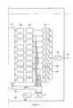
- FIG. 3is a block diagram of the microphone to line output channel in a telephone constructed in accordance with the invention.
- FIG. 4is a block diagram of the line input to speaker channel in a telephone constructed in accordance with the invention.
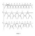
- FIG. 5is a chart illustrating the operation of a sub-band filter
- FIG. 6is a block diagram of a preferred embodiment of one of the voice activity detectors in control circuit 61 (FIG. 2 );
- FIG. 7is a table defining four states according to the outputs of the voice activity detectors
- FIG. 8is a chart showing the response of a system constructed in accordance with the invention to three different noise levels in each of four states;
- FIG. 9is a chart of the settings for the three echo reducing circuits during half duplex operation.
- FIG. 10is a chart illustrating the operation of the invention during double talk or quiet time
- FIG. 11is a chart illustrating the operation of the invention during single talk listen acoustic echo rejection
- FIG. 12is a chart illustrating the operation of the invention during single talk network echo rejection.
- FIG. 13is a block diagram of a two channel acoustic echo reducing circuit constructed in accordance with a preferred embodiment of the invention.
- telephone 10includes a first channel or transmit channel between microphone input 11 and line output 12 and a second channel or receive channel between line input 13 and speaker output 14 . Only apparatus relevant to acoustic echo cancellation is shown in telephone 10 ; i.e. there is a great deal of additional circuitry in each channel in an actual telephone.
- Adaptive echo canceller 15has an input coupled to receive channel 16 and an output coupled to summation network 17 .
- Adaptive echo canceller 15includes a finite impulse response (FIR) filter, the coefficients of which are adjusted to model the acoustic echo path between speaker output 14 and microphone input 11 .
- the output of summation network 17is coupled through non-linear processor (NLP) 18 to Wiener filter 19 .
- the output of filter 19is coupled to line output 12 .
- NLP 18includes attenuation and gain control circuitry for reducing the portions of an echo that are not cancelled in summation network 17 .
- Wiener filter 19provides further attenuation of selected components.
- Adaptive echo canceller 15is controlled by a first control circuit including controller 27 , which has inputs coupled to the microphone input and the speaker output of telephone 10 .
- NLP 18is controlled by a second control circuit including attenuation controller 25 , which has inputs coupled to speech detector 21 , speech detector 22 , speech comparator 23 , and speech comparator 24 .
- the control circuitsare described in the data sheet for the PSB 2170 acoustic echo canceller.
- the echo cancellerhas three operating states. The first is transmit only, the second is receive only, and the third is with both channels on but equally attenuated. As noted above, detecting speech in the transmit channel causes the Wiener filter to be by-passed.
- telephone 30is constructed in accordance with a preferred embodiment of the invention, a first channel (from microphone input 31 to line output 32 ) differs from a second channel (from line input 33 to speaker output 34 ) by the presence of comfort noise generator 37 in the second channel and the absence of an adaptive echo canceller in the second channel.
- the symmetry of the apparatusdoes not mean that each channel operates identically, e.g. that the gain settings of corresponding components is the same. On the contrary, the signal on microphone input 31 is almost always different from the signal on line input 33 in spectral content and amplitude.
- the asymmetry in operation, particularly with respect to sub-band filters 41 and 42is one of several features of the invention.
- Amplifier 44is coupled to microphone input 31 and provides variable gain. Either programmable or automatic gain control can be used to optimize signal strength and range for analog to digital (A/D) converter 47 .
- the output of converter 47is coupled through summation circuit 48 to sub-band filter 41 , described in more detail in FIGS. 3 and 4 .
- the output from sub-band filter 41is coupled through multiplex circuit 51 to non-linear processing (NLP) circuit 53 , which includes a noise reduction circuit, a residual echo cancelling circuit, and a center clipper connected in any order between multiplex circuit 51 and digital to analog (D/A) converter 54 .
- NLPnon-linear processing
- Multiplex circuit 51allows the sub-band filters to be by-passed under certain conditions.
- Amplifier 55couples the output of D/A converter 54 to line output 32 and provides suitable impedance matching and signal levels for line output 32 .
- Non-linear processingrefers to the additional processing techniques that are applied to reduce residual echo signals after the application of adaptive cancellation.
- NLP techniquesare employed only during single talk situations by increasing attenuation or suppression of residual echo and are inactive during double talk. More sophisticated controls have been applied that even allow for adaptive additional suppression even during double talk.
- the most advanced techniquesmonitor the level of residual echo to determine if echo return loss estimates (ERLE) targets have been met. If excessive residual echo remains prohibiting meeting the ERLE goal, the NLP calculates and applies the correct level of additional suppression (on either the near end or far end or both sides of the call) to meet the specified ERLE.
- ERLEecho return loss estimates
- Control circuit 61includes four voice activity detectors having inputs coupled as shown to different points in the receive channel and the transmit channel. For example, a VAD could be coupled to the output of summation circuit 48 rather than to the input and a VAD could be coupled to the output of NLP circuit 53 rather than to the input.
- Adaptive echo canceller 62has an input coupled to the output of NLP circuit 63 and an output coupled to summation network 48 .
- Adaptive echo canceller 62includes a finite impulse response (FIR) filter, the coefficients of which are adjusted to model the acoustic echo path between speaker output 34 and microphone input 31 .
- FIRfinite impulse response
- Comfort noise generator 37is activated to inject a low level of noise into the signal on speaker output 34 .
- Control circuit 61which preferably includes programmable logic or a microprocessor, controls the operation of at least sub-band filters 41 and 42 , NLP circuits 53 and 63 , and adaptive echo canceller 62 in accordance with data from the four voice activity detectors or from data stored in registers within control circuit 61 .
- Amplifiers, such as amplifiers 44 and 65can be operated by control circuit 61 or be in local feedback loops for automatic gain control.
- FIGS. 3 and 4together illustrate the operation of sub-band filters 41 and 42 .
- FIG. 3is a block diagram of a transmit channel and FIG. 4 is a block diagram of a receive channel.
- a handset(not shown) may be included in the telephone and coupled to the lines by appropriate switching circuitry.
- Filters in each bankcan be allocated between two channels in any desired grouping. One can attenuate alternate filters to produce complementary comb filters. In complementary comb filters of the prior art, alternate sub-bands are omitted, not attenuated. In the sub-band filters illustrated in FIGS. 3 and 4 , all sub-bands are available to each channel. Thus, one can group the filters according to the spectral content of each channel, which can not be done with complementary comb filters of the prior art.
- the sub-band filtersare preferably one-third octave filters and are preferably implemented as low order (one to four poles) infinite impulse response (IIR) filters for minimal (1.5-3 ms.) delay.
- IIRinfinite impulse response
- a sub-set of these filtersis chosen in each channel to provide full duplex operation.
- a low order IIR filterdoes not have steep skirts in its response curve and appears unsuitable, it has been found that such filters work quite well in the context of the invention.
- the phase distortion usually associated with IIR filters, making them undesirable,is less with low order filters and occurs near the center of the pass band.
- the overlap in frequency response between adjacent bandsis minimized by initially selecting alternate bands and/or by reversing the phases of the signals in adjacent bands. Any low order filter exhibiting an insertion delay of less than five milliseconds can be used for a sub-band filter.
- Weighting filter 73reduces the amplitude of low frequency signals to provide a more even energy distribution among the bands. Filter 73 can also be used to correct for non-linearities in the frequency response of microphone 71 .
- the output from filter 73is coupled to a first plurality of band pass filters, e.g. one-third octave filters, having progressively higher center frequencies. Much of the apparatus in FIG. 3 is duplicative and only one band is described.
- Band pass filter 74is coupled to filter 73 and to amplitude detector 75 , which, for example, includes a rectifier and a low pass filter. More complex amplitude detectors can be used instead.
- the output from amplitude detector 75is coupled to sample and hold circuit 79 , which provides a stable signal for controller 81 .
- Weighting filter 83receives signals from line input 73 and is coupled to a second plurality of band pass filters.
- Band pass filter 84is coupled to filter 83 and to amplitude detector 85 .
- the output from amplitude detector 85is coupled to sample and hold circuit 86 .
- Controller 81receives the signals from all the sample and hold circuits and contains the logic for comparing the amplitudes of the signals in each band in each channel. Controller 81 is part of control circuit 61 (FIG. 2 ).
- controller 81is coupled to the control inputs of multiplex circuit 91 .
- Each band pass filtersuch as filter 74 , has an output coupled to a signal input of multiplex circuit 91 , which has a plurality of signal output lines coupled to summation circuit 92 .
- the output of summation circuit 92is coupled to de-weighting filter 93 , which has the inverse frequency response of filter 73 .
- the output of de-weighting filter 93is coupled to line output 72 .
- controller 81is coupled to the control inputs to multiplex circuit 96 .
- Each band pass filtersuch as filter 84 , has an output coupled to a signal input of multiplex circuit 96 , which has a plurality of signal output lines coupled to summation circuit 97 .
- the output of summation circuit 97is coupled to de-weighting filter 98 , which as the inverse frequency response of filter 83 .
- the output of de-weighting filter 83is coupled to speaker output 99 .
- Multiplex circuit 91 and multiplex circuit 96are each preferably implemented as a plurality of amplifiers having variable gains individually set by controller 81 . In this way, the spectral content of each channel can be finely tuned for each telephone call.
- the output from each filtercan be adjusted from fully attenuated or minimum gain to maximum amplitude or full gain.
- the filterscan be allocated several different ways. For example, filter 101 ( FIG. 3 ) and filter 102 ( FIG. 4 ) have substantially the same center frequency. If filter 101 produces the loudest signal of all, then the output from filter 101 is coupled to summation circuit 92 by multiplex circuit 91 . The output signal from filter 102 is attenuated by multiplex circuit 96 , while the output signal from filter 103 is less attenuated. Alternate filters in each bank are enabled, allocating the ten bands between the two channels. In this mode, amplifiers in multiplex circuits 91 and 96 are at either minimum gain or maximum gain. While useful as an initial adjustment, the gains are further modified to provide the maximum spectral content possible under a given set of conditions.
- FIG. 5illustrates the operation of one bank of filters.
- Waveform “A”shows all filters at maximum gain.
- the filtersare low order filters and the frequency response curves for the filters do not have steep skirts.
- the gain of alternate filtersis reduced, producing a complementary comb filter response, as illustrated in waveform “B.”
- waveform “C”shows the response curves shown in waveform “C.” The result is no longer complementary comb filters but a pair of filter banks that provide the maximum possible spectral content under the particular circumstances found by the voice activity detectors.
- the telephoneoperates in full duplex all the time.
- the sub-band filtersare immune to non-linearities in the echo path and can be used whether or not there are non-linearities in the echo path. That is, non-linearities do not require half duplex operation as in the prior art.
- FIG. 6is a block diagram of a preferred embodiment of one of the voice activity detectors in control circuit 61 (FIG. 2 ).
- Other VADsknown in the art, could be used instead, although four identical VADs are preferably used.
- the VADsare identical in terms of circuitry, not in terms of the parameters controlling the VADs.
- a digital signal on input 111is coupled to one input of comparator 112 where it is compared with a first threshold.
- the digital signal on input 111is also coupled to one input of comparator 113 where it is compared with a second threshold, which is lower than the first threshold.
- the thresholdsare adjustable and can be set by control circuit 61 (FIG. 2 ).
- the outputs of comparators 112 and 113are coupled to decoder 114 , which decodes the signals to produce a binary output of 00 (zero), 01 (one), or 10 (two).
- Accumulator 115adds the output from decoder 114 to the previous sum on each clock signal for one hundred twenty-eight cycles. Accumulator 115 sums for 2.9 milliseconds and then resets to zero.
- Accumulator 116counts the number of ones from comparator 112 .
- Decoder 114can produce any three numbers in response to the signals on its inputs. In this way data can be skewed or weighted to exaggerate the occurrence of a signal in a particular area, e.g. between the thresholds. A sum is easily and rapidly obtained with very simple hardware and avoids complex calculations for measuring power while obtaining data that represent the rms power of an input signal. A sum is one form of what is referred to herein as statistical data. Another form of statistical data is a count of events, e.g. the number of times a threshold is exceeded. A count can also be weighted. The result is an extremely flexible system that rapidly analyzes an input signal using relatively simple hardware.
- VAD 110is fast because one is creating a sum, not doing a series of complex calculations. Voice detection is easy, quick, and reliable. Less apparent is the fact that the circuit enables one to simulate a root mean square (RMS) calculation without actually having to make the calculation.
- the sum in accumulator 114is indicative of RMS power, although not an exact measure. The circuit thus avoids a significant problem with complex calculations in the, prior art by linear interpolation of a higher order function.
- VAD 110Another subtle but important advantage of VAD 110 is the fact that, while only two bits are being produced, the resolution of the circuit is determined by the resolution of the analog to digital (A/D) converters used to digitize the input signal. If a sixteen-bit A/D converter is used, than the resolution of the circuit is approximately V MAX /64,000, not just V MAX /4 as might be inferred from output data of only two bits. In a preferred embodiment of the invention, the digital comparators work only on the six most significant bits (MSB) of data, which greatly simplifies implementing the invention and increases the speed of the circuit.
- MSBmost significant bits
- VAD 110includes second comparator 119 having an input coupled to the output of accumulator 116 , which counts peaks, i.e. the number of times that the upper threshold (into comparator 112 ) is exceeded.
- the total from accumulator 116is compared with another threshold by comparator 119 and the output of comparator 119 is coupled to one input of OR gate 122 .
- Another input to OR gate 122is coupled to logic (not shown) that provides a logic “1” (true) if the upper threshold is at its minimum. Constructed as shown in FIG.
- the output from AND gate 121is a logic “1” if signal accumulator 114 is above the threshold into comparator 118 AND (the number of peaks is above a threshold OR the peak threshold is at its minimum).
- a logic “1” from AND gate 121indicates that voice is detected.
- telephone 30includes voice activity detector A coupled to microphone input 31 , voice activity detector B coupled to line output 32 , voice activity detector C coupled to line input 33 , and voice activity detector D coupled to speaker output 34 .
- voice activity detector Bis coupled the output of band pass filter bank 41 and voice activity detector D is coupled to the output of band pass filter bank 42 .
- the outputs of the four voice activity detectorsare part of control circuit 61 , which controls filter bank 41 , filter bank 42 , and echo cancelling circuit 62 .
- the dashed linesrepresent control lines rather than signal or data lines.
- control circuit 61The sixteen possible data inputs are re-mapped onto four machine states by control circuit 61 as shown in FIG. 7 .
- DTis a double talk state
- Rxis a receive state
- Txis a transmit state
- Qis a quiet state.
- the control circuitwas an array of logic gates producing the outputs indicated; i.e. fixed or hard coded logic was used. While fixed logic is sufficient for many applications, programmable logic, e.g. using a look-up table, can be used instead.
- voice activity detectorscan be separately adjusted for a particular application.
- voice activity detectors A and Chave the same default threshold and weighting values and voice activity detectors B and D have the same default threshold and weighting values.
- voice activity detectors B and Dexaggerate the difference between low amplitude signals and high amplitude signals more than voice activity detectors A and C.
- High amplitude signalsare given a weight of four rather than two. In part, this is because filter banks 91 and 92 attenuate the signals passing through and some compensation is needed.
- the thresholdsmay vary, depending upon operation conditions.
- a new voice signal entering microphone input 31may or may not be accompanied by a signal from speaker output 34 .
- Amplifier 44maintains the input signal within a suitable range for A/D converter 47 .
- the signals from input 31are digitized in 16-bit A/D converter 47 and coupled to summation network 48 .
- filter bank 41which can be by-passed by using multiplexer 51 . All filters are initially set to minimum attenuation.
- Voice activity detector Blooking at the six most significant bits, senses a large output that could possibly contain an echo and causes filter bank 41 to go to open alternate sub-bands.
- Filter bank 42is made to open the complementary set of sub-bands.
- the filter banksare now configured as complementary comb filters.
- the signal from microphone input 31has its spectrum reduced to the pass bands of half the filters in filter bank 41 .
- the signal from line input 33has its spectrum reduced to the pass bands of half the filters in filter 42 .
- a full spectrum signal passing through either filter aloneis attenuated approximately ⁇ 3 dB.
- a signal passing through filter bank 42 and then through filter bank 41 , configured as complementary comb filters,is attenuated approximately ⁇ 15 dB.
- the filtersare configured as complementary comb filters, two things can happen.
- the signal through filter bank 41might now be attenuated approximately ⁇ 3 dB, indicating new voice, or the signal could be attenuated by more than ⁇ 3 dB, indicating significant content from the receive side.
- the situationis now ambiguous because the content from the receive side could be double talk or echo.
- Voice activity detectors C and Dremove this ambiguity.
- voice activity detector Cindicates voice but voice activity detector D no longer indicates voice, then there was an echo and it is safe to turn on echo canceller 62 . If voice activity detector C indicates voice and voice activity detector D still indicates voice, then there was doubletalk and echo canceller 62 remains off.
- D/A converter 54converts the resulting signal back to analog and amplifier 55 provides impedance matching and proper level for line output 32 .
- voice activity detector and filter bankWhile particular embodiments of voice activity detector and filter bank have been identified and are preferred, the invention will work with other forms of voice activity detector and filter bank.
- the data from the voice activity detectorscan be used to control other devices within telephone 30 , such as comfort noise generator 37 . If neither voice activity detector A nor voice activity detector B detects voice, comfort noise is preferably added to or substituted for the signal from amplifier 39 .
- the state map in FIG. 6does not distinguish between half duplex and full duplex operation.
- the state maprepresents the first level of analysis that is performed on the incoming signals to control the operations of the three echo reducing circuits, the echo canceller, the sub-filters, and the non-linear processor.
- the second level of analysisis noise data collected by the VADs.
- three noise levelsare defined; viz. low noise, high noise, and horrid noise.
- the names and numbers of the noise levelsare arbitrary. Fewer than three levels does not appear desirable. More than five levels may make the circuit “hunt” too much to find a solution. Horrid noise and a “quiet” state may seem inconsistent. Recall that the states are based upon the detection of voice, not just any signal and not noise. Thus, one can have no voice detected, i.e. quiet, and horrid noise.
- This inventionrelates to echo suppression, not noise suppression, although noise can be attenuated with any other signal passing through the system.
- FIG. 8is a chart showing the response of a system constructed in accordance with the invention to three different noise levels in each of four states.
- the right hand column, “LEC,”relates to a line echo canceller, not shown in FIG. 2 but shown in FIG. 13 .
- the sub-band filtersare only partially attenuated in the quiet state.
- a “reset”can be implemented in several ways for an echo canceller. In a digital system, data registers in the echo canceller are set to default values and the output is set to zero. Alternatively, only the output is set to zero. As a further alternative, the echo canceller can be bypassed in the same manner as the sub-band filters. In summary, “reset” means that the echo canceller is turned off or of no effect.
- FIG. 9is a chart of the settings for the three echo reducing circuits during half duplex operation.
- Half duplex operationis limited by timers to no more than one second, often less, before the telephone tries to switch to full duplex operation. This can be done because of the effectiveness of the three-pronged attack on echo.
- a telephone constructed in accordance with the inventionwill only switch to half duplex operation if a howl is detected or if echo cancellation does not exceed 6 dB. Howl is a sustained signal that grows in power, as anyone knows who has heard feedback in a public address system, and is detected by the VADs. Switching to half duplex operation stops the howl immediately because the feedback loop is opened. A user hears a brief chirp and then silence. After 250 ms., the system switches back to full duplex. It is possible but very unlikely that howl may re-start. If so, the system switches to half duplex for another 250 ms.
- echo cancellationWith echo cancellation, the situation is more ambiguous: there are too many possibilities. If echo cancellation does not exceed 6 dB, the system switches to half duplex, resets all registers to default values, then switches to full duplex and starts over. The user may hear a slight echo but hears no clicks, pops, or other sounds.
- Curve 134represents total echo rejection and is the sum of the three techniques. Non-linear processing is essentially attenuation of the signal and contributes 0-24 dB of suppression.
- the adaptive echo cancellerprovides 0-30 dB of cancellation.
- the sub-band filters, operated as described,provide 0-40 dB of suppression.
- the three suppression techniquescan be used in any combination (none, some, or all) as set by control circuit 61 and, in accordance with the invention, are used in a hierarchical order. Specifically, sub-band filters are used first, echo cancelling is used second, and non-linear processing is used third. In accordance with the invention, all three techniques are never applied simultaneously as an initial condition. The sub-band filters are applied first. The adaptive echo canceller is not turned on until an echo has been detected. This helps assure duplex operation if at all possible.
- FIG. 10is a chart showing the suppression of an acoustic echo during double talk.
- the dashed curverepresents a typical room response envelope.
- FIG. 11is a chart showing suppression of an acoustic echo during single talk receive.
- FIG. 12is a chart showing the suppression of network echo during single talk listen. The dashed curve in FIG. 12 represents a typical network response envelope. Note that in all the charts, non-linear processing did not exceed 6 dB of attenuation.
- FIG. 13is a block diagram of a telephone including both acoustic echo cancelling and line echo cancelling.
- the circuit of FIG. 13differs from the circuit of FIG. 2 by the addition of adaptive echo canceller 148 and summation circuit 149 .
- Each of non-linear processors 53 and 63are shown in greater detail as including a noise suppression circuit, a residual echo canceller, and a center clipper.
- the circuitoperates as shown in the charts illustrated in FIGS. 7 , 8 , and 9 .
- the inventionthus provides apparatus for suppressing acoustic echoes and electrical echoes in telephones while providing full duplex operation.
- the echo suppressing circuitis less sensitive to non-linearities in the echo path than circuits of the prior art and provides greater than 60 dB of suppression by selectively applying, in hierarchical order, sub-band filtering, adaptive echo cancelling, and non-linear processing to a signal.
Landscapes
- Engineering & Computer Science (AREA)
- Signal Processing (AREA)
- Cable Transmission Systems, Equalization Of Radio And Reduction Of Echo (AREA)
- Telephone Function (AREA)
Abstract
Description
Claims (28)
Priority Applications (4)
| Application Number | Priority Date | Filing Date | Title |
|---|---|---|---|
| US10/138,615US6904146B2 (en) | 2002-05-03 | 2002-05-03 | Full duplex echo cancelling circuit |
| EP03731071AEP1502418A1 (en) | 2002-05-03 | 2003-05-01 | Full duplex echo cancelling circuit |
| AU2003241339AAU2003241339A1 (en) | 2002-05-03 | 2003-05-01 | Full duplex echo cancelling circuit |
| PCT/US2003/013607WO2003094486A1 (en) | 2002-05-03 | 2003-05-01 | Full duplex echo cancelling circuit |
Applications Claiming Priority (1)
| Application Number | Priority Date | Filing Date | Title |
|---|---|---|---|
| US10/138,615US6904146B2 (en) | 2002-05-03 | 2002-05-03 | Full duplex echo cancelling circuit |
Publications (2)
| Publication Number | Publication Date |
|---|---|
| US20030206624A1 US20030206624A1 (en) | 2003-11-06 |
| US6904146B2true US6904146B2 (en) | 2005-06-07 |
Family
ID=29269384
Family Applications (1)
| Application Number | Title | Priority Date | Filing Date |
|---|---|---|---|
| US10/138,615Expired - LifetimeUS6904146B2 (en) | 2002-05-03 | 2002-05-03 | Full duplex echo cancelling circuit |
Country Status (4)
| Country | Link |
|---|---|
| US (1) | US6904146B2 (en) |
| EP (1) | EP1502418A1 (en) |
| AU (1) | AU2003241339A1 (en) |
| WO (1) | WO2003094486A1 (en) |
Cited By (16)
| Publication number | Priority date | Publication date | Assignee | Title |
|---|---|---|---|---|
| US20030133563A1 (en)* | 2001-12-20 | 2003-07-17 | Thomas Plarre | Communications and control arrangement and operating method for said arrangement |
| US20060280234A1 (en)* | 2005-06-09 | 2006-12-14 | Teranetics, Inc | Single amplifier presample processing circuitry |
| US20070165880A1 (en)* | 2005-12-29 | 2007-07-19 | Microsoft Corporation | Suppression of Acoustic Feedback in Voice Communications |
| US20080043997A1 (en)* | 2006-08-01 | 2008-02-21 | Acoustic Technologies, Inc. | Noise threshold matrix for controlling audio processing |
| US20090052683A1 (en)* | 2007-08-22 | 2009-02-26 | Infineon Technologies Ag | Echo cancellation |
| US20090089054A1 (en)* | 2007-09-28 | 2009-04-02 | Qualcomm Incorporated | Apparatus and method of noise and echo reduction in multiple microphone audio systems |
| US20090089053A1 (en)* | 2007-09-28 | 2009-04-02 | Qualcomm Incorporated | Multiple microphone voice activity detector |
| US20090190774A1 (en)* | 2008-01-29 | 2009-07-30 | Qualcomm Incorporated | Enhanced blind source separation algorithm for highly correlated mixtures |
| US20090214048A1 (en)* | 2008-02-26 | 2009-08-27 | Microsoft Corporation | Harmonic distortion residual echo suppression |
| US20100034373A1 (en)* | 2008-08-08 | 2010-02-11 | Dyba Roman A | Echo canceller with heavy double-talk estimation |
| US20100278067A1 (en)* | 2002-12-23 | 2010-11-04 | Leblanc Wilfrid | Selectively adaptable far-end echo cancellation in a packet voice system |
| US20130217349A1 (en)* | 2012-02-22 | 2013-08-22 | Dialog Semiconductor B.V. | Post Filter for Spectral Domain Echo Cancellers to Handle Non-Linear Echo Components |
| US9940930B1 (en) | 2016-12-07 | 2018-04-10 | Google Llc | Securing audio data |
| US10134396B2 (en) | 2016-12-07 | 2018-11-20 | Google Llc | Preventing of audio attacks |
| US10242673B2 (en) | 2016-12-07 | 2019-03-26 | Google Llc | Preventing of audio attacks using an input and an output hotword detection model |
| US11135426B2 (en) | 2003-12-03 | 2021-10-05 | Google Llc | Personalized network searching |
Families Citing this family (31)
| Publication number | Priority date | Publication date | Assignee | Title |
|---|---|---|---|---|
| US8605911B2 (en) | 2001-07-10 | 2013-12-10 | Dolby International Ab | Efficient and scalable parametric stereo coding for low bitrate audio coding applications |
| ATE288617T1 (en) | 2001-11-29 | 2005-02-15 | Coding Tech Ab | RESTORATION OF HIGH FREQUENCY COMPONENTS |
| SE0202770D0 (en)* | 2002-09-18 | 2002-09-18 | Coding Technologies Sweden Ab | Method of reduction of aliasing is introduced by spectral envelope adjustment in real-valued filterbanks |
| US7009945B1 (en)* | 2003-06-18 | 2006-03-07 | Centillium Communications, Inc. | Dual-mode analog/digital adaptive echo cancellation in communication systems with asymmetric spectrum |
| WO2005046076A1 (en)* | 2003-11-11 | 2005-05-19 | Mitsubishi Denki Kabushiki Kaisha | Echo suppression device |
| US7599432B2 (en)* | 2003-12-08 | 2009-10-06 | Freescale Semiconductor, Inc. | Method and apparatus for dynamically inserting gain in an adaptive filter system |
| KR101215944B1 (en)* | 2004-09-07 | 2012-12-27 | 센시어 피티와이 엘티디 | Hearing protector and Method for sound enhancement |
| KR100800873B1 (en)* | 2005-10-28 | 2008-02-04 | 삼성전자주식회사 | Voice signal detection system and method |
| US8295475B2 (en)* | 2006-01-13 | 2012-10-23 | Microsoft Corporation | Selective glitch detection, clock drift compensation, and anti-clipping in audio echo cancellation |
| US7831035B2 (en)* | 2006-04-28 | 2010-11-09 | Microsoft Corporation | Integration of a microphone array with acoustic echo cancellation and center clipping |
| US7773743B2 (en)* | 2006-04-28 | 2010-08-10 | Microsoft Corporation | Integration of a microphone array with acoustic echo cancellation and residual echo suppression |
| WO2008019080A1 (en)* | 2006-08-04 | 2008-02-14 | Jps Communications, Inc. | Voice modulation recognition in a radio-to-sip adapter |
| US8077857B1 (en) | 2007-03-14 | 2011-12-13 | Clearone Communications, Inc. | Portable speakerphone device with selective mixing |
| US8019076B1 (en) | 2007-03-14 | 2011-09-13 | Clearone Communications, Inc. | Portable speakerphone device and subsystem utilizing false doubletalk detection |
| US8406415B1 (en) | 2007-03-14 | 2013-03-26 | Clearone Communications, Inc. | Privacy modes in an open-air multi-port conferencing device |
| US8654955B1 (en) | 2007-03-14 | 2014-02-18 | Clearone Communications, Inc. | Portable conferencing device with videoconferencing option |
| US7912211B1 (en) | 2007-03-14 | 2011-03-22 | Clearone Communications, Inc. | Portable speakerphone device and subsystem |
| US20080247535A1 (en)* | 2007-04-09 | 2008-10-09 | Microsoft Corporation | Method and apparatus for mitigating impact of nonlinear effects on the quality of audio echo cancellation |
| US20090003586A1 (en)* | 2007-06-28 | 2009-01-01 | Fortemedia, Inc. | Signal processor and method for canceling echo in a communication device |
| US8290142B1 (en) | 2007-11-12 | 2012-10-16 | Clearone Communications, Inc. | Echo cancellation in a portable conferencing device with externally-produced audio |
| US8380253B2 (en) | 2008-02-15 | 2013-02-19 | Microsoft Corporation | Voice switching for voice communication on computers |
| US8275139B2 (en)* | 2008-03-26 | 2012-09-25 | Ittiam Systems (P) Ltd. | Linear full duplex system and method for acoustic echo cancellation |
| US8369251B2 (en)* | 2008-06-20 | 2013-02-05 | Microsoft Corporation | Timestamp quality assessment for assuring acoustic echo canceller operability |
| SE533956C2 (en) | 2009-07-20 | 2011-03-15 | Limes Audio Ab | Device and method for controlling residual cushioning |
| US20130077802A1 (en)* | 2010-05-25 | 2013-03-28 | Nec Corporation | Signal processing method, information processing device and signal processing program |
| CN102291496B (en)* | 2011-09-06 | 2013-08-07 | 华为终端有限公司 | Talking method of terminal and terminal using talking method |
| US9344050B2 (en)* | 2012-10-31 | 2016-05-17 | Maxim Integrated Products, Inc. | Dynamic speaker management with echo cancellation |
| EP2822263B1 (en)* | 2013-07-05 | 2019-03-27 | Sennheiser Communications A/S | Communication device with echo suppression |
| GB2521881B (en) | 2014-04-02 | 2016-02-10 | Imagination Tech Ltd | Auto-tuning of non-linear processor threshold |
| GB2525051B (en) | 2014-09-30 | 2016-04-13 | Imagination Tech Ltd | Detection of acoustic echo cancellation |
| CN118538231B (en)* | 2024-07-04 | 2025-08-01 | 深圳市云天智能通讯有限公司 | Intelligent voice noise reduction method based on satellite communication and related equipment |
Citations (7)
| Publication number | Priority date | Publication date | Assignee | Title |
|---|---|---|---|---|
| US5646990A (en)* | 1995-09-21 | 1997-07-08 | Rockwell International Corporation | Efficient speakerphone anti-howling system |
| US5721730A (en)* | 1995-07-06 | 1998-02-24 | Coherent Communications Systems Corp. | Spectral noise compensation for telecommunication signal processing |
| US5982755A (en)* | 1997-03-06 | 1999-11-09 | Nortel Networks Corporation | System and method for providing high terminal coupling loss in a handsfree terminal |
| US6272106B1 (en)* | 1994-05-06 | 2001-08-07 | Nit Mobile Communications Network, Inc. | Method and device for detecting double-talk, and echo canceler |
| US6385176B1 (en)* | 1998-06-04 | 2002-05-07 | Lucent Technologies Inc. | Communication system based on echo canceler tap profile |
| US6434110B1 (en)* | 1998-03-20 | 2002-08-13 | Cirrus Logic, Inc. | Full-duplex speakerphone circuit including a double-talk detector |
| US6574336B1 (en)* | 1996-06-19 | 2003-06-03 | Nokia Telecommunications Oy | Echo suppressor and non-linear processor of echo canceller |
Family Cites Families (3)
| Publication number | Priority date | Publication date | Assignee | Title |
|---|---|---|---|---|
| US5305307A (en)* | 1991-01-04 | 1994-04-19 | Picturetel Corporation | Adaptive acoustic echo canceller having means for reducing or eliminating echo in a plurality of signal bandwidths |
| US5617472A (en)* | 1993-12-28 | 1997-04-01 | Nec Corporation | Noise suppression of acoustic signal in telephone set |
| US5937060A (en)* | 1996-02-09 | 1999-08-10 | Texas Instruments Incorporated | Residual echo suppression |
- 2002
- 2002-05-03USUS10/138,615patent/US6904146B2/ennot_activeExpired - Lifetime
- 2003
- 2003-05-01AUAU2003241339Apatent/AU2003241339A1/ennot_activeAbandoned
- 2003-05-01WOPCT/US2003/013607patent/WO2003094486A1/ennot_activeApplication Discontinuation
- 2003-05-01EPEP03731071Apatent/EP1502418A1/ennot_activeWithdrawn
Patent Citations (7)
| Publication number | Priority date | Publication date | Assignee | Title |
|---|---|---|---|---|
| US6272106B1 (en)* | 1994-05-06 | 2001-08-07 | Nit Mobile Communications Network, Inc. | Method and device for detecting double-talk, and echo canceler |
| US5721730A (en)* | 1995-07-06 | 1998-02-24 | Coherent Communications Systems Corp. | Spectral noise compensation for telecommunication signal processing |
| US5646990A (en)* | 1995-09-21 | 1997-07-08 | Rockwell International Corporation | Efficient speakerphone anti-howling system |
| US6574336B1 (en)* | 1996-06-19 | 2003-06-03 | Nokia Telecommunications Oy | Echo suppressor and non-linear processor of echo canceller |
| US5982755A (en)* | 1997-03-06 | 1999-11-09 | Nortel Networks Corporation | System and method for providing high terminal coupling loss in a handsfree terminal |
| US6434110B1 (en)* | 1998-03-20 | 2002-08-13 | Cirrus Logic, Inc. | Full-duplex speakerphone circuit including a double-talk detector |
| US6385176B1 (en)* | 1998-06-04 | 2002-05-07 | Lucent Technologies Inc. | Communication system based on echo canceler tap profile |
Non-Patent Citations (6)
| Title |
|---|
| A Frequency Domain Adaptive Echo Canceller with Post-Processing Residual Echo Suppression by Decorrelation, Eneroth & Gänsler, Signal Processing Report SPR-40, Nov. 1997; available at url: www.es.lth.se/sig/publ/ spr/SPR/SPR-40.pdf. |
| Analysis of Subband Impulse Responses in Subband Echo Cancelers, Eneroth & Gänsler, Signal Processing Report SPR-46, Jul. 1999; available at url: www.es.lth.se/ sig/publ/spr/SPR/SPR-46.pdf. |
| Data sheet CS6420 Full-Duplex Speaker Phone Chip, Jun. 1997, Cirrus Logic, Inc. |
| Digital Signal Processing in Telecommunications by Kishan Shenoi, Prentice-Hall, 1995, Chapter 6 (pp. 334-385). |
| ICs for Communications, Acoustic Echo Canceller, PSB2170, Version 1.1, Data Sheet Jan. 1998 Siemens AG. |
| ICs for Communications, Acoustic Echo Canceller, PSB2170, Version 2.1, Preliminary Data Sheet Oct. 1999 infineon technologies. |
Cited By (31)
| Publication number | Priority date | Publication date | Assignee | Title |
|---|---|---|---|---|
| US20030133563A1 (en)* | 2001-12-20 | 2003-07-17 | Thomas Plarre | Communications and control arrangement and operating method for said arrangement |
| US20100278067A1 (en)* | 2002-12-23 | 2010-11-04 | Leblanc Wilfrid | Selectively adaptable far-end echo cancellation in a packet voice system |
| US8526340B2 (en)* | 2002-12-23 | 2013-09-03 | Broadcom Corporation | Selectively adaptable far-end echo cancellation in a packet voice system |
| US8995314B2 (en) | 2002-12-23 | 2015-03-31 | Broadcom Corporation | Selectively adaptable far-end echo cancellation in a packet voice system |
| US11369792B2 (en) | 2003-12-03 | 2022-06-28 | Google Llc | Personalized network searching |
| US11547853B2 (en) | 2003-12-03 | 2023-01-10 | Google Llc | Personalized network searching |
| US11420059B1 (en) | 2003-12-03 | 2022-08-23 | Google Llc | Personalized network searching |
| US11147970B2 (en) | 2003-12-03 | 2021-10-19 | Google Llc | Personalized network searching |
| US11135426B2 (en) | 2003-12-03 | 2021-10-05 | Google Llc | Personalized network searching |
| US7466746B2 (en) | 2005-06-09 | 2008-12-16 | Teranetics, Inc. | Single amplifier presale processing circuitry |
| US20060280234A1 (en)* | 2005-06-09 | 2006-12-14 | Teranetics, Inc | Single amplifier presample processing circuitry |
| US7764634B2 (en) | 2005-12-29 | 2010-07-27 | Microsoft Corporation | Suppression of acoustic feedback in voice communications |
| US20070165880A1 (en)* | 2005-12-29 | 2007-07-19 | Microsoft Corporation | Suppression of Acoustic Feedback in Voice Communications |
| US20080043997A1 (en)* | 2006-08-01 | 2008-02-21 | Acoustic Technologies, Inc. | Noise threshold matrix for controlling audio processing |
| US20090052683A1 (en)* | 2007-08-22 | 2009-02-26 | Infineon Technologies Ag | Echo cancellation |
| US8411871B2 (en)* | 2007-08-22 | 2013-04-02 | Lantiq Deutschland Gmbh | Echo cancellation |
| US8954324B2 (en) | 2007-09-28 | 2015-02-10 | Qualcomm Incorporated | Multiple microphone voice activity detector |
| US20090089054A1 (en)* | 2007-09-28 | 2009-04-02 | Qualcomm Incorporated | Apparatus and method of noise and echo reduction in multiple microphone audio systems |
| US8175871B2 (en)* | 2007-09-28 | 2012-05-08 | Qualcomm Incorporated | Apparatus and method of noise and echo reduction in multiple microphone audio systems |
| US20090089053A1 (en)* | 2007-09-28 | 2009-04-02 | Qualcomm Incorporated | Multiple microphone voice activity detector |
| US8223988B2 (en) | 2008-01-29 | 2012-07-17 | Qualcomm Incorporated | Enhanced blind source separation algorithm for highly correlated mixtures |
| US20090190774A1 (en)* | 2008-01-29 | 2009-07-30 | Qualcomm Incorporated | Enhanced blind source separation algorithm for highly correlated mixtures |
| US8213598B2 (en) | 2008-02-26 | 2012-07-03 | Microsoft Corporation | Harmonic distortion residual echo suppression |
| US20090214048A1 (en)* | 2008-02-26 | 2009-08-27 | Microsoft Corporation | Harmonic distortion residual echo suppression |
| US20100034373A1 (en)* | 2008-08-08 | 2010-02-11 | Dyba Roman A | Echo canceller with heavy double-talk estimation |
| US8295474B2 (en) | 2008-08-08 | 2012-10-23 | Freescale Semiconductor, Inc. | Echo canceller with heavy double-talk estimation |
| US8620232B2 (en)* | 2012-02-22 | 2013-12-31 | Dialog Semiconductor B.V. | Post filter for spectral domain echo cancellers to handle non-linear echo components |
| US20130217349A1 (en)* | 2012-02-22 | 2013-08-22 | Dialog Semiconductor B.V. | Post Filter for Spectral Domain Echo Cancellers to Handle Non-Linear Echo Components |
| US10242673B2 (en) | 2016-12-07 | 2019-03-26 | Google Llc | Preventing of audio attacks using an input and an output hotword detection model |
| US10134396B2 (en) | 2016-12-07 | 2018-11-20 | Google Llc | Preventing of audio attacks |
| US9940930B1 (en) | 2016-12-07 | 2018-04-10 | Google Llc | Securing audio data |
Also Published As
| Publication number | Publication date |
|---|---|
| AU2003241339A1 (en) | 2003-11-17 |
| WO2003094486A1 (en) | 2003-11-13 |
| US20030206624A1 (en) | 2003-11-06 |
| EP1502418A1 (en) | 2005-02-02 |
Similar Documents
| Publication | Publication Date | Title |
|---|---|---|
| US6904146B2 (en) | Full duplex echo cancelling circuit | |
| JP4090505B2 (en) | Non-linear processor of echo suppressor and echo canceler | |
| EP0648397B1 (en) | Method for fail-safe operation in a speaker phone system | |
| EP0366584B1 (en) | Full-duplex digital speakerphone | |
| US5657384A (en) | Full duplex speakerphone | |
| EP1324583B1 (en) | Gain control method for acoustic echo cancellation | |
| FI88570B (en) | TELEFONKRETS SOM LAEMNAR HAENDERNA FRIA | |
| US5099472A (en) | Hands free telecommunication apparatus and method | |
| US5390244A (en) | Method and apparatus for periodic signal detection | |
| US6381224B1 (en) | Method and apparatus for controlling a full-duplex communication system | |
| EP1685697B1 (en) | Method and apparatus for adaptive echo and noise control | |
| EP1256227A1 (en) | Method and apparatus for removing audio artifacts | |
| US6385176B1 (en) | Communication system based on echo canceler tap profile | |
| US5933494A (en) | Echo canceling method and apparatus in a communication device | |
| US6798881B2 (en) | Noise reduction circuit for telephones | |
| US20090067615A1 (en) | Echo cancellation using gain control | |
| CA2263540C (en) | Dynamic optimization of handsfree microphone gain | |
| EP2405587B1 (en) | Echo canceller | |
| US5586180A (en) | Method of automatic speech direction reversal and circuit configuration for implementing the method | |
| Leese | Echo cancellation | |
| US6963642B1 (en) | Band-by-band full duplex communication | |
| CN116647789A (en) | Method for reducing echo in a hearing device | |
| JPS6218836A (en) | Method and circuit for suppression of howling | |
| WO1994000944A1 (en) | Method and apparatus for ringer detection | |
| JPH0611158B2 (en) | Acoustic sneak signal suppression circuit for conference call equipment |
Legal Events
| Date | Code | Title | Description |
|---|---|---|---|
| AS | Assignment | Owner name:ACOUSTIC TECHNOLOGIES, INC., ARIZONA Free format text:ASSIGNMENT OF ASSIGNORS INTEREST;ASSIGNORS:DOMER, STEVEN M.;THOMASSON, SAMUEL L.;REEL/FRAME:012873/0176 Effective date:20020503 | |
| STCF | Information on status: patent grant | Free format text:PATENTED CASE | |
| FPAY | Fee payment | Year of fee payment:4 | |
| AS | Assignment | Owner name:DS&S CHASE, LLC, VIRGINIA Free format text:SECURITY AGREEMENT;ASSIGNOR:ZOUNDS, INC.;REEL/FRAME:022214/0011 Effective date:20081222 Owner name:THE DERWOOD S. CHASE, JR. GRAND TRUST, VIRGINIA Free format text:SECURITY AGREEMENT;ASSIGNOR:ZOUNDS, INC.;REEL/FRAME:022214/0011 Effective date:20081222 Owner name:THE D. SUMNER CHASE, III 2001 IRREVOCABLE TRUST, V Free format text:SECURITY AGREEMENT;ASSIGNOR:ZOUNDS, INC.;REEL/FRAME:022214/0011 Effective date:20081222 Owner name:THE STUART F. CHASE 2001 IRREVOCABLE TRUST, VIRGIN Free format text:SECURITY AGREEMENT;ASSIGNOR:ZOUNDS, INC.;REEL/FRAME:022214/0011 Effective date:20081222 Owner name:STEWART, J. MICHAEL, TEXAS Free format text:SECURITY AGREEMENT;ASSIGNOR:ZOUNDS, INC.;REEL/FRAME:022214/0011 Effective date:20081222 Owner name:DS&S CHASE, LLC,VIRGINIA Free format text:SECURITY AGREEMENT;ASSIGNOR:ZOUNDS, INC.;REEL/FRAME:022214/0011 Effective date:20081222 Owner name:THE DERWOOD S. CHASE, JR. GRAND TRUST,VIRGINIA Free format text:SECURITY AGREEMENT;ASSIGNOR:ZOUNDS, INC.;REEL/FRAME:022214/0011 Effective date:20081222 Owner name:THE D. SUMNER CHASE, III 2001 IRREVOCABLE TRUST,VI Free format text:SECURITY AGREEMENT;ASSIGNOR:ZOUNDS, INC.;REEL/FRAME:022214/0011 Effective date:20081222 Owner name:THE STUART F. CHASE 2001 IRREVOCABLE TRUST,VIRGINI Free format text:SECURITY AGREEMENT;ASSIGNOR:ZOUNDS, INC.;REEL/FRAME:022214/0011 Effective date:20081222 Owner name:STEWART, J. MICHAEL,TEXAS Free format text:SECURITY AGREEMENT;ASSIGNOR:ZOUNDS, INC.;REEL/FRAME:022214/0011 Effective date:20081222 | |
| AS | Assignment | Owner name:DS&S CHASE, LLC, VIRGINIA Free format text:SECURITY AGREEMENT;ASSIGNOR:ZOUNDS, INC.;REEL/FRAME:022440/0370 Effective date:20081222 Owner name:DERWOOD S. CHASE JR., GRAND TRUST, THE, VIRGINIA Free format text:SECURITY AGREEMENT;ASSIGNOR:ZOUNDS, INC.;REEL/FRAME:022440/0370 Effective date:20081222 Owner name:D. SUMNER CHASE, III, 2001 IRREVOCABLE TRUST, THE, Free format text:SECURITY AGREEMENT;ASSIGNOR:ZOUNDS, INC.;REEL/FRAME:022440/0370 Effective date:20081222 Owner name:STUART F. CHASE 2001 IRREVOCABLE TRUST, THE, VIRGI Free format text:SECURITY AGREEMENT;ASSIGNOR:ZOUNDS, INC.;REEL/FRAME:022440/0370 Effective date:20081222 Owner name:STEWART, J. MICHAEL, TEXAS Free format text:SECURITY AGREEMENT;ASSIGNOR:ZOUNDS, INC.;REEL/FRAME:022440/0370 Effective date:20081222 Owner name:MICHAELIS, LAWRENCE L., ARIZONA Free format text:SECURITY AGREEMENT;ASSIGNOR:ZOUNDS, INC.;REEL/FRAME:022440/0370 Effective date:20081222 Owner name:HUDSON FAMILY TRUST, CALIFORNIA Free format text:SECURITY AGREEMENT;ASSIGNOR:ZOUNDS, INC.;REEL/FRAME:022440/0370 Effective date:20081222 Owner name:COSTELLO, JOHN H., GEORGIA Free format text:SECURITY AGREEMENT;ASSIGNOR:ZOUNDS, INC.;REEL/FRAME:022440/0370 Effective date:20081222 Owner name:POCONO LAKE PROPERTIES, LP, PENNSYLVANIA Free format text:SECURITY AGREEMENT;ASSIGNOR:ZOUNDS, INC.;REEL/FRAME:022440/0370 Effective date:20081222 Owner name:LINSKY, BARRY R., NEW YORK Free format text:SECURITY AGREEMENT;ASSIGNOR:ZOUNDS, INC.;REEL/FRAME:022440/0370 Effective date:20081222 Owner name:WHEALE MANAGEMENT LLC, NEW JERSEY Free format text:SECURITY AGREEMENT;ASSIGNOR:ZOUNDS, INC.;REEL/FRAME:022440/0370 Effective date:20081222 Owner name:KYLE D. BARNES AND MAUREEN A. MCGAREY, MAINE Free format text:SECURITY AGREEMENT;ASSIGNOR:ZOUNDS, INC.;REEL/FRAME:022440/0370 Effective date:20081222 Owner name:CONKLIN, TERRENCE J., NEW HAMPSHIRE Free format text:SECURITY AGREEMENT;ASSIGNOR:ZOUNDS, INC.;REEL/FRAME:022440/0370 Effective date:20081222 Owner name:ALLEN, RICHARD D., DELAWARE Free format text:SECURITY AGREEMENT;ASSIGNOR:ZOUNDS, INC.;REEL/FRAME:022440/0370 Effective date:20081222 Owner name:NIEMASKI JR., WALTER, CALIFORNIA Free format text:SECURITY AGREEMENT;ASSIGNOR:ZOUNDS, INC.;REEL/FRAME:022440/0370 Effective date:20081222 Owner name:TROPEA, FRANK, FLORIDA Free format text:SECURITY AGREEMENT;ASSIGNOR:ZOUNDS, INC.;REEL/FRAME:022440/0370 Effective date:20081222 Owner name:STOUT, HENRY A., MASSACHUSETTS Free format text:SECURITY AGREEMENT;ASSIGNOR:ZOUNDS, INC.;REEL/FRAME:022440/0370 Effective date:20081222 Owner name:POMPIZZI FAMILY LIMITED PARTNERSHIP, ILLINOIS Free format text:SECURITY AGREEMENT;ASSIGNOR:ZOUNDS, INC.;REEL/FRAME:022440/0370 Effective date:20081222 Owner name:GEIER JR., PHILIP H., NEW YORK Free format text:SECURITY AGREEMENT;ASSIGNOR:ZOUNDS, INC.;REEL/FRAME:022440/0370 Effective date:20081222 Owner name:HICKSON, B.E., CANADA Free format text:SECURITY AGREEMENT;ASSIGNOR:ZOUNDS, INC.;REEL/FRAME:022440/0370 Effective date:20081222 Owner name:JAMES R. LANCASTER, TTEE JAMES R. LANCASTER REVOCA Free format text:SECURITY AGREEMENT;ASSIGNOR:ZOUNDS, INC.;REEL/FRAME:022440/0370 Effective date:20081222 Owner name:COLEMAN, CRAIG G., MAINE Free format text:SECURITY AGREEMENT;ASSIGNOR:ZOUNDS, INC.;REEL/FRAME:022440/0370 Effective date:20081222 Owner name:BETTY & ROBERT SHOBERT, FLORIDA Free format text:SECURITY AGREEMENT;ASSIGNOR:ZOUNDS, INC.;REEL/FRAME:022440/0370 Effective date:20081222 Owner name:REGEN, THOMAS W., NEW YORK Free format text:SECURITY AGREEMENT;ASSIGNOR:ZOUNDS, INC.;REEL/FRAME:022440/0370 Effective date:20081222 Owner name:MASSAD & MASSAD INVESTMENTS, LTD., TEXAS Free format text:SECURITY AGREEMENT;ASSIGNOR:ZOUNDS, INC.;REEL/FRAME:022440/0370 Effective date:20081222 Owner name:SCOTT, DAVID B., VIRGINIA Free format text:SECURITY AGREEMENT;ASSIGNOR:ZOUNDS, INC.;REEL/FRAME:022440/0370 Effective date:20081222 Owner name:C. BRADFORD JEFFRIES LIVING TRUST (1994), CALIFORN Free format text:SECURITY AGREEMENT;ASSIGNOR:ZOUNDS, INC.;REEL/FRAME:022440/0370 Effective date:20081222 Owner name:ROBERT S. JULIAN, TRUSTEE, INSURANCE TRUST OF 12/2 Free format text:SECURITY AGREEMENT;ASSIGNOR:ZOUNDS, INC.;REEL/FRAME:022440/0370 Effective date:20081222 Owner name:HINTLIAN, VARNEY J., MAINE Free format text:SECURITY AGREEMENT;ASSIGNOR:ZOUNDS, INC.;REEL/FRAME:022440/0370 Effective date:20081222 Owner name:BOLWELL, FARLEY, COLORADO Free format text:SECURITY AGREEMENT;ASSIGNOR:ZOUNDS, INC.;REEL/FRAME:022440/0370 Effective date:20081222 Owner name:SOLLOTT, MICHAEL H., NEW YORK Free format text:SECURITY AGREEMENT;ASSIGNOR:ZOUNDS, INC.;REEL/FRAME:022440/0370 Effective date:20081222 Owner name:FOLLAND FAMILY INVESTMENT COMPANY, ILLINOIS Free format text:SECURITY AGREEMENT;ASSIGNOR:ZOUNDS, INC.;REEL/FRAME:022440/0370 Effective date:20081222 Owner name:BEALL FAMILY TRUST, CALIFORNIA Free format text:SECURITY AGREEMENT;ASSIGNOR:ZOUNDS, INC.;REEL/FRAME:022440/0370 Effective date:20081222 Owner name:STOCK, STEVEN W., WISCONSIN Free format text:SECURITY AGREEMENT;ASSIGNOR:ZOUNDS, INC.;REEL/FRAME:022440/0370 Effective date:20081222 Owner name:PATTERSON, ELIZABETH T., VIRGINIA Free format text:SECURITY AGREEMENT;ASSIGNOR:ZOUNDS, INC.;REEL/FRAME:022440/0370 Effective date:20081222 Owner name:BORTS, RICHARD, MAINE Free format text:SECURITY AGREEMENT;ASSIGNOR:ZOUNDS, INC.;REEL/FRAME:022440/0370 Effective date:20081222 Owner name:STONE, JEFFREY M., TEXAS Free format text:SECURITY AGREEMENT;ASSIGNOR:ZOUNDS, INC.;REEL/FRAME:022440/0370 Effective date:20081222 Owner name:LANDIN, ROBERT, TEXAS Free format text:SECURITY AGREEMENT;ASSIGNOR:ZOUNDS, INC.;REEL/FRAME:022440/0370 Effective date:20081222 Owner name:GOLDBERG, JEFFREY L., NEW JERSEY Free format text:SECURITY AGREEMENT;ASSIGNOR:ZOUNDS, INC.;REEL/FRAME:022440/0370 Effective date:20081222 Owner name:LAMBERTI, STEVE, TEXAS Free format text:SECURITY AGREEMENT;ASSIGNOR:ZOUNDS, INC.;REEL/FRAME:022440/0370 Effective date:20081222 Owner name:ROBERT P. HAUPTFUHRER FAMILY PARTNERSHIP, PENNSYLV Free format text:SECURITY AGREEMENT;ASSIGNOR:ZOUNDS, INC.;REEL/FRAME:022440/0370 Effective date:20081222 Owner name:SCHELLENBACH, PETER, ILLINOIS Free format text:SECURITY AGREEMENT;ASSIGNOR:ZOUNDS, INC.;REEL/FRAME:022440/0370 Effective date:20081222 Owner name:R. PATRICK AND VICTORIA E. MIELE, FLORIDA Free format text:SECURITY AGREEMENT;ASSIGNOR:ZOUNDS, INC.;REEL/FRAME:022440/0370 Effective date:20081222 Owner name:O'CONNOR, RALPH S., TEXAS Free format text:SECURITY AGREEMENT;ASSIGNOR:ZOUNDS, INC.;REEL/FRAME:022440/0370 Effective date:20081222 Owner name:O'CONNOR, RALPH S.,TEXAS Free format text:SECURITY AGREEMENT;ASSIGNOR:ZOUNDS, INC.;REEL/FRAME:022440/0370 Effective date:20081222 Owner name:DS&S CHASE, LLC,VIRGINIA Free format text:SECURITY AGREEMENT;ASSIGNOR:ZOUNDS, INC.;REEL/FRAME:022440/0370 Effective date:20081222 Owner name:DERWOOD S. CHASE JR., GRAND TRUST, THE,VIRGINIA Free format text:SECURITY AGREEMENT;ASSIGNOR:ZOUNDS, INC.;REEL/FRAME:022440/0370 Effective date:20081222 Owner name:STUART F. CHASE 2001 IRREVOCABLE TRUST, THE,VIRGIN Free format text:SECURITY AGREEMENT;ASSIGNOR:ZOUNDS, INC.;REEL/FRAME:022440/0370 Effective date:20081222 Owner name:STEWART, J. MICHAEL,TEXAS Free format text:SECURITY AGREEMENT;ASSIGNOR:ZOUNDS, INC.;REEL/FRAME:022440/0370 Effective date:20081222 Owner name:MICHAELIS, LAWRENCE L.,ARIZONA Free format text:SECURITY AGREEMENT;ASSIGNOR:ZOUNDS, INC.;REEL/FRAME:022440/0370 Effective date:20081222 Owner name:HUDSON FAMILY TRUST,CALIFORNIA Free format text:SECURITY AGREEMENT;ASSIGNOR:ZOUNDS, INC.;REEL/FRAME:022440/0370 Effective date:20081222 Owner name:COSTELLO, JOHN H.,GEORGIA Free format text:SECURITY AGREEMENT;ASSIGNOR:ZOUNDS, INC.;REEL/FRAME:022440/0370 Effective date:20081222 Owner name:POCONO LAKE PROPERTIES, LP,PENNSYLVANIA Free format text:SECURITY AGREEMENT;ASSIGNOR:ZOUNDS, INC.;REEL/FRAME:022440/0370 Effective date:20081222 Owner name:LINSKY, BARRY R.,NEW YORK Free format text:SECURITY AGREEMENT;ASSIGNOR:ZOUNDS, INC.;REEL/FRAME:022440/0370 Effective date:20081222 Owner name:WHEALE MANAGEMENT LLC,NEW JERSEY Free format text:SECURITY AGREEMENT;ASSIGNOR:ZOUNDS, INC.;REEL/FRAME:022440/0370 Effective date:20081222 Owner name:KYLE D. BARNES AND MAUREEN A. MCGAREY,MAINE Free format text:SECURITY AGREEMENT;ASSIGNOR:ZOUNDS, INC.;REEL/FRAME:022440/0370 Effective date:20081222 Owner name:CONKLIN, TERRENCE J.,NEW HAMPSHIRE Free format text:SECURITY AGREEMENT;ASSIGNOR:ZOUNDS, INC.;REEL/FRAME:022440/0370 Effective date:20081222 Owner name:ALLEN, RICHARD D.,DELAWARE Free format text:SECURITY AGREEMENT;ASSIGNOR:ZOUNDS, INC.;REEL/FRAME:022440/0370 Effective date:20081222 Owner name:NIEMASKI JR., WALTER,CALIFORNIA Free format text:SECURITY AGREEMENT;ASSIGNOR:ZOUNDS, INC.;REEL/FRAME:022440/0370 Effective date:20081222 Owner name:TROPEA, FRANK,FLORIDA Free format text:SECURITY AGREEMENT;ASSIGNOR:ZOUNDS, INC.;REEL/FRAME:022440/0370 Effective date:20081222 Owner name:STOUT, HENRY A.,MASSACHUSETTS Free format text:SECURITY AGREEMENT;ASSIGNOR:ZOUNDS, INC.;REEL/FRAME:022440/0370 Effective date:20081222 Owner name:POMPIZZI FAMILY LIMITED PARTNERSHIP,ILLINOIS Free format text:SECURITY AGREEMENT;ASSIGNOR:ZOUNDS, INC.;REEL/FRAME:022440/0370 Effective date:20081222 Owner name:GEIER JR., PHILIP H.,NEW YORK Free format text:SECURITY AGREEMENT;ASSIGNOR:ZOUNDS, INC.;REEL/FRAME:022440/0370 Effective date:20081222 Owner name:HICKSON, B.E.,CANADA Free format text:SECURITY AGREEMENT;ASSIGNOR:ZOUNDS, INC.;REEL/FRAME:022440/0370 Effective date:20081222 Owner name:COLEMAN, CRAIG G.,MAINE Free format text:SECURITY AGREEMENT;ASSIGNOR:ZOUNDS, INC.;REEL/FRAME:022440/0370 Effective date:20081222 Owner name:BETTY & ROBERT SHOBERT,FLORIDA Free format text:SECURITY AGREEMENT;ASSIGNOR:ZOUNDS, INC.;REEL/FRAME:022440/0370 Effective date:20081222 Owner name:REGEN, THOMAS W.,NEW YORK Free format text:SECURITY AGREEMENT;ASSIGNOR:ZOUNDS, INC.;REEL/FRAME:022440/0370 Effective date:20081222 Owner name:MASSAD & MASSAD INVESTMENTS, LTD.,TEXAS Free format text:SECURITY AGREEMENT;ASSIGNOR:ZOUNDS, INC.;REEL/FRAME:022440/0370 Effective date:20081222 Owner name:SCOTT, DAVID B.,VIRGINIA Free format text:SECURITY AGREEMENT;ASSIGNOR:ZOUNDS, INC.;REEL/FRAME:022440/0370 Effective date:20081222 Owner name:C. BRADFORD JEFFRIES LIVING TRUST (1994),CALIFORNI Free format text:SECURITY AGREEMENT;ASSIGNOR:ZOUNDS, INC.;REEL/FRAME:022440/0370 Effective date:20081222 Owner name:HINTLIAN, VARNEY J.,MAINE Free format text:SECURITY AGREEMENT;ASSIGNOR:ZOUNDS, INC.;REEL/FRAME:022440/0370 Effective date:20081222 Owner name:BOLWELL, FARLEY,COLORADO Free format text:SECURITY AGREEMENT;ASSIGNOR:ZOUNDS, INC.;REEL/FRAME:022440/0370 Effective date:20081222 Owner name:SOLLOTT, MICHAEL H.,NEW YORK Free format text:SECURITY AGREEMENT;ASSIGNOR:ZOUNDS, INC.;REEL/FRAME:022440/0370 Effective date:20081222 Owner name:FOLLAND FAMILY INVESTMENT COMPANY,ILLINOIS Free format text:SECURITY AGREEMENT;ASSIGNOR:ZOUNDS, INC.;REEL/FRAME:022440/0370 Effective date:20081222 Owner name:BEALL FAMILY TRUST,CALIFORNIA Free format text:SECURITY AGREEMENT;ASSIGNOR:ZOUNDS, INC.;REEL/FRAME:022440/0370 Effective date:20081222 Owner name:STOCK, STEVEN W.,WISCONSIN Free format text:SECURITY AGREEMENT;ASSIGNOR:ZOUNDS, INC.;REEL/FRAME:022440/0370 Effective date:20081222 Owner name:PATTERSON, ELIZABETH T.,VIRGINIA Free format text:SECURITY AGREEMENT;ASSIGNOR:ZOUNDS, INC.;REEL/FRAME:022440/0370 Effective date:20081222 Owner name:BORTS, RICHARD,MAINE Free format text:SECURITY AGREEMENT;ASSIGNOR:ZOUNDS, INC.;REEL/FRAME:022440/0370 Effective date:20081222 Owner name:STONE, JEFFREY M.,TEXAS Free format text:SECURITY AGREEMENT;ASSIGNOR:ZOUNDS, INC.;REEL/FRAME:022440/0370 Effective date:20081222 Owner name:LANDIN, ROBERT,TEXAS Free format text:SECURITY AGREEMENT;ASSIGNOR:ZOUNDS, INC.;REEL/FRAME:022440/0370 Effective date:20081222 Owner name:GOLDBERG, JEFFREY L.,NEW JERSEY Free format text:SECURITY AGREEMENT;ASSIGNOR:ZOUNDS, INC.;REEL/FRAME:022440/0370 Effective date:20081222 Owner name:LAMBERTI, STEVE,TEXAS Free format text:SECURITY AGREEMENT;ASSIGNOR:ZOUNDS, INC.;REEL/FRAME:022440/0370 Effective date:20081222 Owner name:ROBERT P. HAUPTFUHRER FAMILY PARTNERSHIP,PENNSYLVA Free format text:SECURITY AGREEMENT;ASSIGNOR:ZOUNDS, INC.;REEL/FRAME:022440/0370 Effective date:20081222 Owner name:SCHELLENBACH, PETER,ILLINOIS Free format text:SECURITY AGREEMENT;ASSIGNOR:ZOUNDS, INC.;REEL/FRAME:022440/0370 Effective date:20081222 Owner name:R. PATRICK AND VICTORIA E. MIELE,FLORIDA Free format text:SECURITY AGREEMENT;ASSIGNOR:ZOUNDS, INC.;REEL/FRAME:022440/0370 Effective date:20081222 Owner name:DERWOOD S. CHASE, JR. GRAND TRUST, THE,VIRGINIA Free format text:SECURITY AGREEMENT;ASSIGNOR:ZOUNDS, INC.;REEL/FRAME:022440/0370 Effective date:20081222 Owner name:D. SUMNER CHASE, III 2001 IRREVOCABLE TRUST, THE,V Free format text:SECURITY AGREEMENT;ASSIGNOR:ZOUNDS, INC.;REEL/FRAME:022440/0370 Effective date:20081222 Owner name:BARNES, KYLE D.,MAINE Free format text:SECURITY AGREEMENT;ASSIGNOR:ZOUNDS, INC.;REEL/FRAME:022440/0370 Effective date:20081222 Owner name:MCGAREY, MAUREEN A.,MAINE Free format text:SECURITY AGREEMENT;ASSIGNOR:ZOUNDS, INC.;REEL/FRAME:022440/0370 Effective date:20081222 Owner name:NIEMASKI, WALTER, JR.,CALIFORNIA Free format text:SECURITY AGREEMENT;ASSIGNOR:ZOUNDS, INC.;REEL/FRAME:022440/0370 Effective date:20081222 Owner name:GEIER, PHILIP H., JR.,NEW YORK Free format text:SECURITY AGREEMENT;ASSIGNOR:ZOUNDS, INC.;REEL/FRAME:022440/0370 Effective date:20081222 Owner name:LANCASTER, JAMES R., TTEE JAMES R. LANCASTER REVOC Free format text:SECURITY AGREEMENT;ASSIGNOR:ZOUNDS, INC.;REEL/FRAME:022440/0370 Effective date:20081222 Owner name:SHOBERT, BETTY,FLORIDA Free format text:SECURITY AGREEMENT;ASSIGNOR:ZOUNDS, INC.;REEL/FRAME:022440/0370 Effective date:20081222 Owner name:SHOBERT, ROBERT,FLORIDA Free format text:SECURITY AGREEMENT;ASSIGNOR:ZOUNDS, INC.;REEL/FRAME:022440/0370 Effective date:20081222 Owner name:JULIAN, ROBERT S., TRUSTEE, INSURANCE TRUST OF 12/ Free format text:SECURITY AGREEMENT;ASSIGNOR:ZOUNDS, INC.;REEL/FRAME:022440/0370 Effective date:20081222 Owner name:MIELE, R. PATRICK,FLORIDA Free format text:SECURITY AGREEMENT;ASSIGNOR:ZOUNDS, INC.;REEL/FRAME:022440/0370 Effective date:20081222 Owner name:MIELE, VICTORIA E.,FLORIDA Free format text:SECURITY AGREEMENT;ASSIGNOR:ZOUNDS, INC.;REEL/FRAME:022440/0370 Effective date:20081222 Owner name:DERWOOD S. CHASE, JR. GRAND TRUST, THE, VIRGINIA Free format text:SECURITY AGREEMENT;ASSIGNOR:ZOUNDS, INC.;REEL/FRAME:022440/0370 Effective date:20081222 Owner name:D. SUMNER CHASE, III 2001 IRREVOCABLE TRUST, THE, Free format text:SECURITY AGREEMENT;ASSIGNOR:ZOUNDS, INC.;REEL/FRAME:022440/0370 Effective date:20081222 Owner name:BARNES, KYLE D., MAINE Free format text:SECURITY AGREEMENT;ASSIGNOR:ZOUNDS, INC.;REEL/FRAME:022440/0370 Effective date:20081222 Owner name:MCGAREY, MAUREEN A., MAINE Free format text:SECURITY AGREEMENT;ASSIGNOR:ZOUNDS, INC.;REEL/FRAME:022440/0370 Effective date:20081222 Owner name:NIEMASKI, WALTER, JR., CALIFORNIA Free format text:SECURITY AGREEMENT;ASSIGNOR:ZOUNDS, INC.;REEL/FRAME:022440/0370 Effective date:20081222 Owner name:GEIER, PHILIP H., JR., NEW YORK Free format text:SECURITY AGREEMENT;ASSIGNOR:ZOUNDS, INC.;REEL/FRAME:022440/0370 Effective date:20081222 Owner name:SHOBERT, BETTY, FLORIDA Free format text:SECURITY AGREEMENT;ASSIGNOR:ZOUNDS, INC.;REEL/FRAME:022440/0370 Effective date:20081222 Owner name:SHOBERT, ROBERT, FLORIDA Free format text:SECURITY AGREEMENT;ASSIGNOR:ZOUNDS, INC.;REEL/FRAME:022440/0370 Effective date:20081222 Owner name:MIELE, R. PATRICK, FLORIDA Free format text:SECURITY AGREEMENT;ASSIGNOR:ZOUNDS, INC.;REEL/FRAME:022440/0370 Effective date:20081222 Owner name:MIELE, VICTORIA E., FLORIDA Free format text:SECURITY AGREEMENT;ASSIGNOR:ZOUNDS, INC.;REEL/FRAME:022440/0370 Effective date:20081222 | |
| FPAY | Fee payment | Year of fee payment:8 | |
| FEPP | Fee payment procedure | Free format text:PAT HOLDER NO LONGER CLAIMS SMALL ENTITY STATUS, ENTITY STATUS SET TO UNDISCOUNTED (ORIGINAL EVENT CODE: STOL); ENTITY STATUS OF PATENT OWNER: LARGE ENTITY | |
| AS | Assignment | Owner name:CIRRUS LOGIC INC., TEXAS Free format text:MERGER;ASSIGNOR:ACOUSTIC TECHNOLOGIES, INC.;REEL/FRAME:035837/0052 Effective date:20150604 | |
| FPAY | Fee payment | Year of fee payment:12 |