US6903442B2 - Semiconductor component having backside pin contacts - Google Patents
Semiconductor component having backside pin contactsDownload PDFInfo
- Publication number
- US6903442B2 US6903442B2US10/232,549US23254902AUS6903442B2US 6903442 B2US6903442 B2US 6903442B2US 23254902 AUS23254902 AUS 23254902AUS 6903442 B2US6903442 B2US 6903442B2
- Authority
- US
- United States
- Prior art keywords
- contacts
- die
- component
- substrate
- conductive members
- Prior art date
- Legal status (The legal status is an assumption and is not a legal conclusion. Google has not performed a legal analysis and makes no representation as to the accuracy of the status listed.)
- Expired - Lifetime, expires
Links
Images


Classifications
- H—ELECTRICITY
- H01—ELECTRIC ELEMENTS
- H01L—SEMICONDUCTOR DEVICES NOT COVERED BY CLASS H10
- H01L23/00—Details of semiconductor or other solid state devices
- H01L23/28—Encapsulations, e.g. encapsulating layers, coatings, e.g. for protection
- H01L23/31—Encapsulations, e.g. encapsulating layers, coatings, e.g. for protection characterised by the arrangement or shape
- H01L23/3107—Encapsulations, e.g. encapsulating layers, coatings, e.g. for protection characterised by the arrangement or shape the device being completely enclosed
- H01L23/3114—Encapsulations, e.g. encapsulating layers, coatings, e.g. for protection characterised by the arrangement or shape the device being completely enclosed the device being a chip scale package, e.g. CSP
- H—ELECTRICITY
- H01—ELECTRIC ELEMENTS
- H01L—SEMICONDUCTOR DEVICES NOT COVERED BY CLASS H10
- H01L21/00—Processes or apparatus adapted for the manufacture or treatment of semiconductor or solid state devices or of parts thereof
- H01L21/70—Manufacture or treatment of devices consisting of a plurality of solid state components formed in or on a common substrate or of parts thereof; Manufacture of integrated circuit devices or of parts thereof
- H01L21/71—Manufacture of specific parts of devices defined in group H01L21/70
- H01L21/768—Applying interconnections to be used for carrying current between separate components within a device comprising conductors and dielectrics
- H01L21/76801—Applying interconnections to be used for carrying current between separate components within a device comprising conductors and dielectrics characterised by the formation and the after-treatment of the dielectrics, e.g. smoothing
- H01L21/76829—Applying interconnections to be used for carrying current between separate components within a device comprising conductors and dielectrics characterised by the formation and the after-treatment of the dielectrics, e.g. smoothing characterised by the formation of thin functional dielectric layers, e.g. dielectric etch-stop, barrier, capping or liner layers
- H01L21/76831—Applying interconnections to be used for carrying current between separate components within a device comprising conductors and dielectrics characterised by the formation and the after-treatment of the dielectrics, e.g. smoothing characterised by the formation of thin functional dielectric layers, e.g. dielectric etch-stop, barrier, capping or liner layers in via holes or trenches, e.g. non-conductive sidewall liners
- H—ELECTRICITY
- H01—ELECTRIC ELEMENTS
- H01L—SEMICONDUCTOR DEVICES NOT COVERED BY CLASS H10
- H01L21/00—Processes or apparatus adapted for the manufacture or treatment of semiconductor or solid state devices or of parts thereof
- H01L21/70—Manufacture or treatment of devices consisting of a plurality of solid state components formed in or on a common substrate or of parts thereof; Manufacture of integrated circuit devices or of parts thereof
- H01L21/71—Manufacture of specific parts of devices defined in group H01L21/70
- H01L21/768—Applying interconnections to be used for carrying current between separate components within a device comprising conductors and dielectrics
- H01L21/76898—Applying interconnections to be used for carrying current between separate components within a device comprising conductors and dielectrics formed through a semiconductor substrate
- H—ELECTRICITY
- H01—ELECTRIC ELEMENTS
- H01L—SEMICONDUCTOR DEVICES NOT COVERED BY CLASS H10
- H01L23/00—Details of semiconductor or other solid state devices
- H01L23/48—Arrangements for conducting electric current to or from the solid state body in operation, e.g. leads, terminal arrangements ; Selection of materials therefor
- H01L23/481—Internal lead connections, e.g. via connections, feedthrough structures
- H—ELECTRICITY
- H01—ELECTRIC ELEMENTS
- H01L—SEMICONDUCTOR DEVICES NOT COVERED BY CLASS H10
- H01L24/00—Arrangements for connecting or disconnecting semiconductor or solid-state bodies; Methods or apparatus related thereto
- H01L24/01—Means for bonding being attached to, or being formed on, the surface to be connected, e.g. chip-to-package, die-attach, "first-level" interconnects; Manufacturing methods related thereto
- H01L24/10—Bump connectors ; Manufacturing methods related thereto
- H01L24/11—Manufacturing methods
- H—ELECTRICITY
- H01—ELECTRIC ELEMENTS
- H01L—SEMICONDUCTOR DEVICES NOT COVERED BY CLASS H10
- H01L24/00—Arrangements for connecting or disconnecting semiconductor or solid-state bodies; Methods or apparatus related thereto
- H01L24/01—Means for bonding being attached to, or being formed on, the surface to be connected, e.g. chip-to-package, die-attach, "first-level" interconnects; Manufacturing methods related thereto
- H01L24/10—Bump connectors ; Manufacturing methods related thereto
- H01L24/12—Structure, shape, material or disposition of the bump connectors prior to the connecting process
- H01L24/13—Structure, shape, material or disposition of the bump connectors prior to the connecting process of an individual bump connector
- H—ELECTRICITY
- H01—ELECTRIC ELEMENTS
- H01L—SEMICONDUCTOR DEVICES NOT COVERED BY CLASS H10
- H01L25/00—Assemblies consisting of a plurality of semiconductor or other solid state devices
- H01L25/03—Assemblies consisting of a plurality of semiconductor or other solid state devices all the devices being of a type provided for in a single subclass of subclasses H10B, H10D, H10F, H10H, H10K or H10N, e.g. assemblies of rectifier diodes
- H01L25/04—Assemblies consisting of a plurality of semiconductor or other solid state devices all the devices being of a type provided for in a single subclass of subclasses H10B, H10D, H10F, H10H, H10K or H10N, e.g. assemblies of rectifier diodes the devices not having separate containers
- H01L25/065—Assemblies consisting of a plurality of semiconductor or other solid state devices all the devices being of a type provided for in a single subclass of subclasses H10B, H10D, H10F, H10H, H10K or H10N, e.g. assemblies of rectifier diodes the devices not having separate containers the devices being of a type provided for in group H10D89/00
- H01L25/0657—Stacked arrangements of devices
- H—ELECTRICITY
- H01—ELECTRIC ELEMENTS
- H01L—SEMICONDUCTOR DEVICES NOT COVERED BY CLASS H10
- H01L25/00—Assemblies consisting of a plurality of semiconductor or other solid state devices
- H01L25/50—Multistep manufacturing processes of assemblies consisting of devices, the devices being individual devices of subclass H10D or integrated devices of class H10
- H—ELECTRICITY
- H01—ELECTRIC ELEMENTS
- H01L—SEMICONDUCTOR DEVICES NOT COVERED BY CLASS H10
- H01L2224/00—Indexing scheme for arrangements for connecting or disconnecting semiconductor or solid-state bodies and methods related thereto as covered by H01L24/00
- H01L2224/01—Means for bonding being attached to, or being formed on, the surface to be connected, e.g. chip-to-package, die-attach, "first-level" interconnects; Manufacturing methods related thereto
- H01L2224/02—Bonding areas; Manufacturing methods related thereto
- H01L2224/04—Structure, shape, material or disposition of the bonding areas prior to the connecting process
- H01L2224/05—Structure, shape, material or disposition of the bonding areas prior to the connecting process of an individual bonding area
- H01L2224/05001—Internal layers
- H01L2224/05005—Structure
- H01L2224/05009—Bonding area integrally formed with a via connection of the semiconductor or solid-state body
- H—ELECTRICITY
- H01—ELECTRIC ELEMENTS
- H01L—SEMICONDUCTOR DEVICES NOT COVERED BY CLASS H10
- H01L2224/00—Indexing scheme for arrangements for connecting or disconnecting semiconductor or solid-state bodies and methods related thereto as covered by H01L24/00
- H01L2224/01—Means for bonding being attached to, or being formed on, the surface to be connected, e.g. chip-to-package, die-attach, "first-level" interconnects; Manufacturing methods related thereto
- H01L2224/02—Bonding areas; Manufacturing methods related thereto
- H01L2224/04—Structure, shape, material or disposition of the bonding areas prior to the connecting process
- H01L2224/05—Structure, shape, material or disposition of the bonding areas prior to the connecting process of an individual bonding area
- H01L2224/05001—Internal layers
- H01L2224/05099—Material
- H01L2224/051—Material with a principal constituent of the material being a metal or a metalloid, e.g. boron [B], silicon [Si], germanium [Ge], arsenic [As], antimony [Sb], tellurium [Te] and polonium [Po], and alloys thereof
- H01L2224/05163—Material with a principal constituent of the material being a metal or a metalloid, e.g. boron [B], silicon [Si], germanium [Ge], arsenic [As], antimony [Sb], tellurium [Te] and polonium [Po], and alloys thereof the principal constituent melting at a temperature of greater than 1550°C
- H01L2224/05172—Vanadium [V] as principal constituent
- H—ELECTRICITY
- H01—ELECTRIC ELEMENTS
- H01L—SEMICONDUCTOR DEVICES NOT COVERED BY CLASS H10
- H01L2224/00—Indexing scheme for arrangements for connecting or disconnecting semiconductor or solid-state bodies and methods related thereto as covered by H01L24/00
- H01L2224/01—Means for bonding being attached to, or being formed on, the surface to be connected, e.g. chip-to-package, die-attach, "first-level" interconnects; Manufacturing methods related thereto
- H01L2224/02—Bonding areas; Manufacturing methods related thereto
- H01L2224/04—Structure, shape, material or disposition of the bonding areas prior to the connecting process
- H01L2224/05—Structure, shape, material or disposition of the bonding areas prior to the connecting process of an individual bonding area
- H01L2224/0554—External layer
- H01L2224/0556—Disposition
- H01L2224/0557—Disposition the external layer being disposed on a via connection of the semiconductor or solid-state body
- H—ELECTRICITY
- H01—ELECTRIC ELEMENTS
- H01L—SEMICONDUCTOR DEVICES NOT COVERED BY CLASS H10
- H01L2224/00—Indexing scheme for arrangements for connecting or disconnecting semiconductor or solid-state bodies and methods related thereto as covered by H01L24/00
- H01L2224/01—Means for bonding being attached to, or being formed on, the surface to be connected, e.g. chip-to-package, die-attach, "first-level" interconnects; Manufacturing methods related thereto
- H01L2224/02—Bonding areas; Manufacturing methods related thereto
- H01L2224/04—Structure, shape, material or disposition of the bonding areas prior to the connecting process
- H01L2224/05—Structure, shape, material or disposition of the bonding areas prior to the connecting process of an individual bonding area
- H01L2224/0554—External layer
- H01L2224/0556—Disposition
- H01L2224/05571—Disposition the external layer being disposed in a recess of the surface
- H01L2224/05572—Disposition the external layer being disposed in a recess of the surface the external layer extending out of an opening
- H—ELECTRICITY
- H01—ELECTRIC ELEMENTS
- H01L—SEMICONDUCTOR DEVICES NOT COVERED BY CLASS H10
- H01L2224/00—Indexing scheme for arrangements for connecting or disconnecting semiconductor or solid-state bodies and methods related thereto as covered by H01L24/00
- H01L2224/01—Means for bonding being attached to, or being formed on, the surface to be connected, e.g. chip-to-package, die-attach, "first-level" interconnects; Manufacturing methods related thereto
- H01L2224/10—Bump connectors; Manufacturing methods related thereto
- H01L2224/11—Manufacturing methods
- H01L2224/113—Manufacturing methods by local deposition of the material of the bump connector
- H01L2224/1133—Manufacturing methods by local deposition of the material of the bump connector in solid form
- H01L2224/1134—Stud bumping, i.e. using a wire-bonding apparatus
- H—ELECTRICITY
- H01—ELECTRIC ELEMENTS
- H01L—SEMICONDUCTOR DEVICES NOT COVERED BY CLASS H10
- H01L2224/00—Indexing scheme for arrangements for connecting or disconnecting semiconductor or solid-state bodies and methods related thereto as covered by H01L24/00
- H01L2224/01—Means for bonding being attached to, or being formed on, the surface to be connected, e.g. chip-to-package, die-attach, "first-level" interconnects; Manufacturing methods related thereto
- H01L2224/10—Bump connectors; Manufacturing methods related thereto
- H01L2224/12—Structure, shape, material or disposition of the bump connectors prior to the connecting process
- H01L2224/13—Structure, shape, material or disposition of the bump connectors prior to the connecting process of an individual bump connector
- H01L2224/13001—Core members of the bump connector
- H01L2224/13099—Material
- H01L2224/131—Material with a principal constituent of the material being a metal or a metalloid, e.g. boron [B], silicon [Si], germanium [Ge], arsenic [As], antimony [Sb], tellurium [Te] and polonium [Po], and alloys thereof
- H—ELECTRICITY
- H01—ELECTRIC ELEMENTS
- H01L—SEMICONDUCTOR DEVICES NOT COVERED BY CLASS H10
- H01L2224/00—Indexing scheme for arrangements for connecting or disconnecting semiconductor or solid-state bodies and methods related thereto as covered by H01L24/00
- H01L2224/01—Means for bonding being attached to, or being formed on, the surface to be connected, e.g. chip-to-package, die-attach, "first-level" interconnects; Manufacturing methods related thereto
- H01L2224/10—Bump connectors; Manufacturing methods related thereto
- H01L2224/15—Structure, shape, material or disposition of the bump connectors after the connecting process
- H01L2224/16—Structure, shape, material or disposition of the bump connectors after the connecting process of an individual bump connector
- H—ELECTRICITY
- H01—ELECTRIC ELEMENTS
- H01L—SEMICONDUCTOR DEVICES NOT COVERED BY CLASS H10
- H01L2225/00—Details relating to assemblies covered by the group H01L25/00 but not provided for in its subgroups
- H01L2225/03—All the devices being of a type provided for in the same main group of the same subclass of class H10, e.g. assemblies of rectifier diodes
- H01L2225/04—All the devices being of a type provided for in the same main group of the same subclass of class H10, e.g. assemblies of rectifier diodes the devices not having separate containers
- H01L2225/065—All the devices being of a type provided for in the same main group of the same subclass of class H10
- H01L2225/06503—Stacked arrangements of devices
- H01L2225/06541—Conductive via connections through the device, e.g. vertical interconnects, through silicon via [TSV]
- H—ELECTRICITY
- H01—ELECTRIC ELEMENTS
- H01L—SEMICONDUCTOR DEVICES NOT COVERED BY CLASS H10
- H01L2225/00—Details relating to assemblies covered by the group H01L25/00 but not provided for in its subgroups
- H01L2225/03—All the devices being of a type provided for in the same main group of the same subclass of class H10, e.g. assemblies of rectifier diodes
- H01L2225/04—All the devices being of a type provided for in the same main group of the same subclass of class H10, e.g. assemblies of rectifier diodes the devices not having separate containers
- H01L2225/065—All the devices being of a type provided for in the same main group of the same subclass of class H10
- H01L2225/06503—Stacked arrangements of devices
- H01L2225/06582—Housing for the assembly, e.g. chip scale package [CSP]
- H01L2225/06586—Housing with external bump or bump-like connectors
- H—ELECTRICITY
- H01—ELECTRIC ELEMENTS
- H01L—SEMICONDUCTOR DEVICES NOT COVERED BY CLASS H10
- H01L24/00—Arrangements for connecting or disconnecting semiconductor or solid-state bodies; Methods or apparatus related thereto
- H01L24/01—Means for bonding being attached to, or being formed on, the surface to be connected, e.g. chip-to-package, die-attach, "first-level" interconnects; Manufacturing methods related thereto
- H01L24/02—Bonding areas ; Manufacturing methods related thereto
- H01L24/03—Manufacturing methods
- H—ELECTRICITY
- H01—ELECTRIC ELEMENTS
- H01L—SEMICONDUCTOR DEVICES NOT COVERED BY CLASS H10
- H01L24/00—Arrangements for connecting or disconnecting semiconductor or solid-state bodies; Methods or apparatus related thereto
- H01L24/01—Means for bonding being attached to, or being formed on, the surface to be connected, e.g. chip-to-package, die-attach, "first-level" interconnects; Manufacturing methods related thereto
- H01L24/02—Bonding areas ; Manufacturing methods related thereto
- H01L24/04—Structure, shape, material or disposition of the bonding areas prior to the connecting process
- H01L24/05—Structure, shape, material or disposition of the bonding areas prior to the connecting process of an individual bonding area
- H—ELECTRICITY
- H01—ELECTRIC ELEMENTS
- H01L—SEMICONDUCTOR DEVICES NOT COVERED BY CLASS H10
- H01L2924/00—Indexing scheme for arrangements or methods for connecting or disconnecting semiconductor or solid-state bodies as covered by H01L24/00
- H01L2924/0001—Technical content checked by a classifier
- H—ELECTRICITY
- H01—ELECTRIC ELEMENTS
- H01L—SEMICONDUCTOR DEVICES NOT COVERED BY CLASS H10
- H01L2924/00—Indexing scheme for arrangements or methods for connecting or disconnecting semiconductor or solid-state bodies as covered by H01L24/00
- H01L2924/01—Chemical elements
- H01L2924/01005—Boron [B]
- H—ELECTRICITY
- H01—ELECTRIC ELEMENTS
- H01L—SEMICONDUCTOR DEVICES NOT COVERED BY CLASS H10
- H01L2924/00—Indexing scheme for arrangements or methods for connecting or disconnecting semiconductor or solid-state bodies as covered by H01L24/00
- H01L2924/01—Chemical elements
- H01L2924/01006—Carbon [C]
- H—ELECTRICITY
- H01—ELECTRIC ELEMENTS
- H01L—SEMICONDUCTOR DEVICES NOT COVERED BY CLASS H10
- H01L2924/00—Indexing scheme for arrangements or methods for connecting or disconnecting semiconductor or solid-state bodies as covered by H01L24/00
- H01L2924/01—Chemical elements
- H01L2924/01013—Aluminum [Al]
- H—ELECTRICITY
- H01—ELECTRIC ELEMENTS
- H01L—SEMICONDUCTOR DEVICES NOT COVERED BY CLASS H10
- H01L2924/00—Indexing scheme for arrangements or methods for connecting or disconnecting semiconductor or solid-state bodies as covered by H01L24/00
- H01L2924/01—Chemical elements
- H01L2924/01019—Potassium [K]
- H—ELECTRICITY
- H01—ELECTRIC ELEMENTS
- H01L—SEMICONDUCTOR DEVICES NOT COVERED BY CLASS H10
- H01L2924/00—Indexing scheme for arrangements or methods for connecting or disconnecting semiconductor or solid-state bodies as covered by H01L24/00
- H01L2924/01—Chemical elements
- H01L2924/01022—Titanium [Ti]
- H—ELECTRICITY
- H01—ELECTRIC ELEMENTS
- H01L—SEMICONDUCTOR DEVICES NOT COVERED BY CLASS H10
- H01L2924/00—Indexing scheme for arrangements or methods for connecting or disconnecting semiconductor or solid-state bodies as covered by H01L24/00
- H01L2924/01—Chemical elements
- H01L2924/01024—Chromium [Cr]
- H—ELECTRICITY
- H01—ELECTRIC ELEMENTS
- H01L—SEMICONDUCTOR DEVICES NOT COVERED BY CLASS H10
- H01L2924/00—Indexing scheme for arrangements or methods for connecting or disconnecting semiconductor or solid-state bodies as covered by H01L24/00
- H01L2924/01—Chemical elements
- H01L2924/01029—Copper [Cu]
- H—ELECTRICITY
- H01—ELECTRIC ELEMENTS
- H01L—SEMICONDUCTOR DEVICES NOT COVERED BY CLASS H10
- H01L2924/00—Indexing scheme for arrangements or methods for connecting or disconnecting semiconductor or solid-state bodies as covered by H01L24/00
- H01L2924/01—Chemical elements
- H01L2924/0103—Zinc [Zn]
- H—ELECTRICITY
- H01—ELECTRIC ELEMENTS
- H01L—SEMICONDUCTOR DEVICES NOT COVERED BY CLASS H10
- H01L2924/00—Indexing scheme for arrangements or methods for connecting or disconnecting semiconductor or solid-state bodies as covered by H01L24/00
- H01L2924/01—Chemical elements
- H01L2924/01033—Arsenic [As]
- H—ELECTRICITY
- H01—ELECTRIC ELEMENTS
- H01L—SEMICONDUCTOR DEVICES NOT COVERED BY CLASS H10
- H01L2924/00—Indexing scheme for arrangements or methods for connecting or disconnecting semiconductor or solid-state bodies as covered by H01L24/00
- H01L2924/01—Chemical elements
- H01L2924/01042—Molybdenum [Mo]
- H—ELECTRICITY
- H01—ELECTRIC ELEMENTS
- H01L—SEMICONDUCTOR DEVICES NOT COVERED BY CLASS H10
- H01L2924/00—Indexing scheme for arrangements or methods for connecting or disconnecting semiconductor or solid-state bodies as covered by H01L24/00
- H01L2924/01—Chemical elements
- H01L2924/01046—Palladium [Pd]
- H—ELECTRICITY
- H01—ELECTRIC ELEMENTS
- H01L—SEMICONDUCTOR DEVICES NOT COVERED BY CLASS H10
- H01L2924/00—Indexing scheme for arrangements or methods for connecting or disconnecting semiconductor or solid-state bodies as covered by H01L24/00
- H01L2924/01—Chemical elements
- H01L2924/01047—Silver [Ag]
- H—ELECTRICITY
- H01—ELECTRIC ELEMENTS
- H01L—SEMICONDUCTOR DEVICES NOT COVERED BY CLASS H10
- H01L2924/00—Indexing scheme for arrangements or methods for connecting or disconnecting semiconductor or solid-state bodies as covered by H01L24/00
- H01L2924/01—Chemical elements
- H01L2924/01072—Hafnium [Hf]
- H—ELECTRICITY
- H01—ELECTRIC ELEMENTS
- H01L—SEMICONDUCTOR DEVICES NOT COVERED BY CLASS H10
- H01L2924/00—Indexing scheme for arrangements or methods for connecting or disconnecting semiconductor or solid-state bodies as covered by H01L24/00
- H01L2924/01—Chemical elements
- H01L2924/01073—Tantalum [Ta]
- H—ELECTRICITY
- H01—ELECTRIC ELEMENTS
- H01L—SEMICONDUCTOR DEVICES NOT COVERED BY CLASS H10
- H01L2924/00—Indexing scheme for arrangements or methods for connecting or disconnecting semiconductor or solid-state bodies as covered by H01L24/00
- H01L2924/01—Chemical elements
- H01L2924/01074—Tungsten [W]
- H—ELECTRICITY
- H01—ELECTRIC ELEMENTS
- H01L—SEMICONDUCTOR DEVICES NOT COVERED BY CLASS H10
- H01L2924/00—Indexing scheme for arrangements or methods for connecting or disconnecting semiconductor or solid-state bodies as covered by H01L24/00
- H01L2924/01—Chemical elements
- H01L2924/01075—Rhenium [Re]
- H—ELECTRICITY
- H01—ELECTRIC ELEMENTS
- H01L—SEMICONDUCTOR DEVICES NOT COVERED BY CLASS H10
- H01L2924/00—Indexing scheme for arrangements or methods for connecting or disconnecting semiconductor or solid-state bodies as covered by H01L24/00
- H01L2924/01—Chemical elements
- H01L2924/01077—Iridium [Ir]
- H—ELECTRICITY
- H01—ELECTRIC ELEMENTS
- H01L—SEMICONDUCTOR DEVICES NOT COVERED BY CLASS H10
- H01L2924/00—Indexing scheme for arrangements or methods for connecting or disconnecting semiconductor or solid-state bodies as covered by H01L24/00
- H01L2924/01—Chemical elements
- H01L2924/01078—Platinum [Pt]
- H—ELECTRICITY
- H01—ELECTRIC ELEMENTS
- H01L—SEMICONDUCTOR DEVICES NOT COVERED BY CLASS H10
- H01L2924/00—Indexing scheme for arrangements or methods for connecting or disconnecting semiconductor or solid-state bodies as covered by H01L24/00
- H01L2924/01—Chemical elements
- H01L2924/01079—Gold [Au]
- H—ELECTRICITY
- H01—ELECTRIC ELEMENTS
- H01L—SEMICONDUCTOR DEVICES NOT COVERED BY CLASS H10
- H01L2924/00—Indexing scheme for arrangements or methods for connecting or disconnecting semiconductor or solid-state bodies as covered by H01L24/00
- H01L2924/013—Alloys
- H01L2924/014—Solder alloys
- H—ELECTRICITY
- H01—ELECTRIC ELEMENTS
- H01L—SEMICONDUCTOR DEVICES NOT COVERED BY CLASS H10
- H01L2924/00—Indexing scheme for arrangements or methods for connecting or disconnecting semiconductor or solid-state bodies as covered by H01L24/00
- H01L2924/10—Details of semiconductor or other solid state devices to be connected
- H01L2924/11—Device type
- H01L2924/12—Passive devices, e.g. 2 terminal devices
- H01L2924/1204—Optical Diode
- H01L2924/12042—LASER
- H—ELECTRICITY
- H01—ELECTRIC ELEMENTS
- H01L—SEMICONDUCTOR DEVICES NOT COVERED BY CLASS H10
- H01L2924/00—Indexing scheme for arrangements or methods for connecting or disconnecting semiconductor or solid-state bodies as covered by H01L24/00
- H01L2924/10—Details of semiconductor or other solid state devices to be connected
- H01L2924/11—Device type
- H01L2924/14—Integrated circuits
- H01L2924/143—Digital devices
- H01L2924/1433—Application-specific integrated circuit [ASIC]
- Y—GENERAL TAGGING OF NEW TECHNOLOGICAL DEVELOPMENTS; GENERAL TAGGING OF CROSS-SECTIONAL TECHNOLOGIES SPANNING OVER SEVERAL SECTIONS OF THE IPC; TECHNICAL SUBJECTS COVERED BY FORMER USPC CROSS-REFERENCE ART COLLECTIONS [XRACs] AND DIGESTS
- Y10—TECHNICAL SUBJECTS COVERED BY FORMER USPC
- Y10S—TECHNICAL SUBJECTS COVERED BY FORMER USPC CROSS-REFERENCE ART COLLECTIONS [XRACs] AND DIGESTS
- Y10S438/00—Semiconductor device manufacturing: process
- Y10S438/977—Thinning or removal of substrate
Definitions
- This inventionrelates generally to semiconductor manufacture and packaging. More particularly, this invention relates to a semiconductor component with backside contacts, to a method for fabricating the component, and to systems incorporating the component.
- Semiconductor componentssuch as chip scale packages and bumped dice, are being manufactured with a smaller outline and with a higher pin count than conventional plastic or ceramic packages.
- This type of semiconductor componenttypically includes a dense area array of terminal contacts, such as solder bumps in a ball grid array (BGA) or metal pins in a pin grid array (PGA).
- BGAball grid array
- PGApin grid array
- the terminal contactspermit the component to be surface mounted to a supporting substrate, such as a package substrate, a module substrate or a circuit board.
- the quality, reliability and cost of these types of componentsis often dependent on the fabrication method.
- the formation of the terminal contacts and the electrical paths between the terminal contacts and the diceare a particular concern.
- reliable electrical interconnectionsmust be made between the terminal contacts for the component, and contacts on the dice contained within the component.
- the die contactscomprise thin film aluminum bond pads in electrical communication with integrated circuits on the dice.
- Some prior art componentsrequire relatively complicated interconnections, such as metal beams or wires, formed of gold, gold plated materials, aluminum, copper or solder using a bonding process, such as thermosonic bonding or wire bonding.
- the interconnections, and their bonds with the die contacts and the terminal contactsare subjected to stresses during manufacture, and during subsequent use of the component. These stresses can cause the interconnections to weaken or pull apart, adversely affecting the reliability of the components.
- the present inventionis directed to an improved semiconductor component having novel backside contacts and conductive member interconnections.
- the present inventionis directed to a novel wafer level fabrication method for manufacturing the component in volume using conventional equipment.
- an improved semiconductor componentIn accordance with the present invention, an improved semiconductor component, a method for fabricating the component, and electronic assemblies incorporating the component are provided.
- the componentincludes a semiconductor die having a thinned semiconductor substrate with a circuit side (front side) and a back side.
- the dieincludes integrated circuits and a pattern of die contacts on the circuit side in electrical communication with the integrated circuits.
- the componentincludes an array of pin contacts on the backside, and conductive members in the substrate in electrical communication with the die contacts and the pin contacts.
- Each conductive memberis formed by an opening in a die contact and substrate and a conductive material in the opening.
- each conductive memberis exposed on the back side of the substrate to form a pin contact.
- the componentcan also include redistribution conductors and contacts on the circuit side in electrical communication with the conductive members.
- the conductive memberscomprise openings having insulated sidewalls plated with a conductive material.
- the conductive membersare configured for mating physical and electrical engagement with a pin contact on an adjacent component of a stacked assembly.
- the method for fabricating the componentincludes the step of providing multiple semiconductor dice on substrate, such as a semiconductor wafer, having a circuit side and a back side.
- the methodalso includes the steps of forming openings in the die contacts and part way through the substrate, forming an electrically insulating passivation layer on the circuit side and in the openings, and depositing a conductive material in the openings to form the conductive members.
- the methodcan include the steps of thinning and etching the substrate from the back side to expose terminal portions of the conductive members forming the pin contacts, and then singulating the dice from the wafer.
- the methodcan also include the steps of forming redistribution conductors on the circuit side in electrical communication with the conductive members and circuit side contacts on the redistribution conductors.
- the pin contactsare formed on the back side of the component using steps performed predominantly on the circuit side of the component.
- the pin contactsprovide electrical connection points for performing various wafer level test procedures.
- the componentcan be integrated to form electronic assemblies such as modules, circuit boards and stacked arrays.
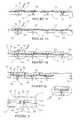
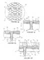
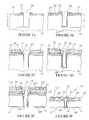
- FIGS. 1A-1Iare schematic cross sectional views illustrating steps in a method for fabricating a male semiconductor component in accordance with the invention
- FIG. 2Ais a plan view taken along line 2 A— 2 A of FIG. 1A illustrating semiconductor dice on a wafer used in the fabrication method;
- FIG. 2Bis an enlarged plan view taken along line 2 B— 2 B of FIG. 1B illustrating an opening in a die contact;
- FIG. 2Cis an enlarged view taken along line 2 C of FIG. 1C illustrating a passivation layers in the opening and on the circuit side;
- FIG. 2Dis an enlarged view taken along line 2 D of FIG. 1D illustrating an insulating layer on the circuit side;
- FIG. 2Eis an enlarged view taken along line 2 E of FIG. 1E illustrating a conductive member and a redistribution conductor;
- FIG. 2Fis an enlarged view taken along line 2 F of FIG. 1F illustrating the conductive member following thinning of the wafer;
- FIG. 2Gis an enlarged view taken along line 2 G of FIG. 1G illustrating the conductive member and a terminal contact thereon following etching of the wafer;
- FIG. 2His an enlarged view taken along line 2 H of FIG. 1H illustrating circuit side contacts on the component;
- FIG. 2Iis an enlarged view taken along line 2 I of FIG. 1I illustrating the completed male component
- FIG. 2Jis an enlarged cross sectional view taken along section line 2 J— 2 J of FIG. 2A illustrating a die contact and integrated circuits on the male component;
- FIG. 2Kis a cross sectional view taken along line 2 K— 2 K of FIG. 1E illustrating redistribution conductors on the male component;
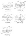
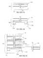
- FIGS. 3A-3Eare schematic cross sectional views of alternate embodiments of the male component of FIG. 2I ;
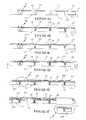
- FIGS. 4A-4Fare schematic cross sectional views illustrating steps in a fabrication method for an alternate embodiment female component having female conductive members
- FIG. 5Ais an enlarged view taken along line 5 A of FIG. 4A illustrating an opening in a die contact
- FIG. 5Bis an enlarged view taken along line 5 B of FIG. 4B illustrating passivation layers
- FIG. 5Cis an enlarged view taken along line 5 C of FIG. 4C illustrating an insulating layer
- FIG. 5Dis an enlarged view taken along line 5 D of FIG. 4D illustrating redistribution conductors
- FIG. 5Eis an enlarged view taken along line 5 E of FIG. 4E illustrating an outer insulating layer
- FIG. 5Fis an enlarged schematic cross sectional view illustrating the completed alternate embodiment female component.
- FIGS. 6A-6Care schematic cross sectional views illustrating electronic assemblies fabricated using components constructed in accordance with the invention.
- semiconductor componentrefers to an electronic element that includes a semiconductor die.
- Exemplary semiconductor componentsinclude semiconductor packages, chip scale packages, semiconductor dice, BGA devices, and semiconductor wafers.
- FIGS. 1A-1I and 2 A- 2 Ksteps in the method for fabricating a semiconductor component 16 ( FIG. 2I ) in accordance with the invention are illustrated.
- a plurality of semiconductor dice 10are provided, for fabricating a plurality of semiconductor components 16 (FIG. 2 I).
- the dice 10can comprise conventional semiconductor dice having a desired configuration.
- each die 10can comprise a dynamic random access memory (DRAM), a static random access memory (SRAM), a flash memory, a microprocessor, a digital signal processor (DSP) or an application specific integrated circuit (ASIC).
- DRAMdynamic random access memory
- SRAMstatic random access memory
- flash memorya flash memory
- microprocessordigital signal processor
- DSPdigital signal processor
- ASICapplication specific integrated circuit
- the dice 10 and the components 16can have any polygonal shape. In the illustrative embodiment, the dice 10 and the components 16 are rectangular in shape, but other polygonal shapes, such as square or hexagonal can also be utilized.
- the dice 10are contained on a semiconductor wafer 12 .
- the methodis performed on an entire semiconductor wafer 12 , it is to be understood that the method can be performed on a portion of a wafer, on a panel, or on any other substrate that contains multiple semiconductor dice.
- the wafer 12 and each die 10includes a semiconductor substrate 14 having a circuit side 20 (front side or first side) wherein integrated circuits 24 ( FIG. 2J ) are located, and a back side 22 (second side).
- the circuit side 20 and the back side 22are the major planar surfaces of each die 10 .
- each die 10includes a pattern of die contacts 18 formed on the circuit side 20 , in a selected pattern, such as a dense area array, in electrical communication with the integrated circuits 24 ( FIG. 2J ) on the die 10 .
- the die contacts 18are the device bond pads for the die 10 .
- the die contacts 18are generally square, planar pads having a desired size (e.g., 220-100 ⁇ m) and spacing. However, other polygonal shapes for the die contacts 18 , such as rectangular, or circular shaped can also be employed. For simplicity the die contacts 18 are illustrated in a single row along the center of the die 10 . However, the die contacts 18 can be arranged in any desired pattern including such as edge connect, end connect, and dense area arrays such as grid arrays and micro grid arrays.
- the die contacts 18can comprise a conventional metal such as aluminum, copper and alloys thereof.
- an insulating layer 26 on the circuit side 20such as a layer of silicon dioxide, electrically insulates the integrated circuits 18 from the bulk of the substrate 14 .
- openings 28are formed through the die contacts 18 and part way through the substrate 14 .
- the openings 28can be formed using an etching process, a laser machining process, an ion milling process, or combinations of these processes.
- One method for forming the openings 28combines etching and laser machining processes.
- an etch mask(not shown) and an etching process can be used to form the openings 28 through the die contacts 18 .
- a wet etchantcan be used to etch the die contacts 18 .
- one suitable wet etchantis H 3 PO 4 .
- the die contacts 18can also be made with the openings 28 therein.
- the openings 28can be formed during deposition of the die contacts 18 . In this case the etching and laser machining steps described above can be eliminated.
- the openings 28 in the die contacts 18are generally circular, and have an outside diameter OD that is smaller than the width W of the die contacts 18 .
- the die contacts 18following formation of the openings 28 , the die contacts 18 resemble square donuts having metal around their peripheries, but no metal in the center.
- the diameter OD of the openings 28is about one half the width W of the die contacts 18 .
- the openings 28 following the etching step, but prior to the laser machining stepsurround a portion of the substrate 14 , such that the die contacts 18 and the openings 28 form targets, or a pattern recognition system, for a laser beam to counter bore the openings 28 part way through the substrate 14 .
- the openings 28can have a depth (D) of about 6 ⁇ m to 300 ⁇ m or greater, and a diameter (OD) of about 10 ⁇ m to 2 mils or greater.
- One suitable laser system for performing the laser machining stepis manufactured by XSIL LTD of Dublin, Ireland, and is designated a model no. XISE 200.
- Another suitable laser system for performing the laser machining stepis manufactured by Electro Scientific, Inc., of Portland, Oreg. and is designated a Model No. 2700.
- a representative laser fluence for forming the openings 28 through a silicon substrate having a thickness of about 28 mils (711 ⁇ m),is from 2 to 10 watts/per opening at a pulse duration of 20-25 ns, and at a repetition rate of up to several thousand per second.
- the wavelength of the laser beamcan be a standard UV wavelength (e.g., 355 nm).
- a cleaning stepcan be performed in which the openings 28 are cleaned using a suitable wet or dry etchant.
- a suitable wet etchant for cleaning the openings 28 with the substrate 14 comprising siliconis tetramethylammoniumhydroxide (TMAH).
- an electrically insulating passivation layer 30is formed on the circuit side 20 of the wafer 12 , and an electrically insulating passivation layer 32 is formed in the openings 28 .
- the passivation layer 30electrically insulates the circuit side 20
- the passivation layer 32electrically insulates the openings 28 .
- the passivation layers 30 , 32can comprise an electrically insulating material such as a glass, a polymer or an oxide formed as a layer of a required thickness.
- the passivation layers 30 , 32are a single layer of the same material deposited to a same thickness. However, the passivation layers 30 , 32 can be different materials deposited in different stages and with different thicknesses.
- the passivation layers 30 , 32have a thickness T 1 ( FIG. 2C ) that is less than the diameter OD of the openings 28 , such that the sidewalls of the openings 28 are coated, but the openings 28 are not completely closed.
- a thickness range for the passivation layers 30 , 32can be from 0.10 ⁇ m to 100 ⁇ m or greater.
- One suitable material for both passivation layers 30 , 32is borophosphosilicate glass (BPSG) which can be deposited to a required thickness using a spin-on or other suitable process.
- BPSGborophosphosilicate glass
- a photoimageable polymer such as polyimidecan also be deposited to a required thickness using a spin-on, electrophoretic or other suitable process.
- parylene polymerscan be deposited from the vapor phase by a process similar to vacuum metallization at pressures of about 0.1 torr.
- Suitable polymersinclude parylene C, parylene N, and parylene D. Parylene is available from Advanced Coating of Tempe, Ariz.
- One suitable deposition apparatus for forming the passivation layers 30 , 32 of paryleneis a portable parylene deposition system, designated a model PDS 2010 LABCOATER 2, manufactured by Specialty Coating Systems, of Indianapolis, Ind.
- the passivation layer 30can also comprise a first electrically insulating material formed on the circuit side 20 , and the passivation layer 32 can comprise a second electrically insulating material formed in the openings 28 .
- the passivation layer 30 on the circuit side 20can comprise a glass or a polymer layer formed as previously described, and the passivation layers 32 in the openings 28 can comprise silicon dioxide formed using a growth or deposition process.
- silicon dioxidecan be grown by exposure of the silicon substrate 12 within the openings 28 to oxygen at an elevated temperature (e.g., 950° C.).
- the passivation layers 30 , 32can be patterned by etching, or other suitable process, to expose portions 34 of the die contacts 18 .
- a mask(not shown) having openings aligned with the die contacts 18 can be used with a wet etchant to etch the passivation layers 30 , 32 .
- one suitable etchantcomprises HF.
- the passivation layers 30 , 32comprising parylene an oxygen plasma process or a laser ablation process rather than an etchant can be employed.
- an electrically insulating polymer layer 36is formed on the circuit side 20 and patterned such that the exposed portions 34 of the die contacts 18 remain exposed.
- the polymer layer 36preferably comprises a low dielectric constant (low k) polymer such as polyimide, polybenzoxazole (PBO), or benzocyclobutene (BCB).
- low krefers to a material with a dielectric constant of less than about 3.9.
- the polymer layer 36can be deposited to a desired thickness T 2 using a suitable deposition process such as spin-on, positive displacement through a nozzle, screen printing or stenciling.
- a suitable deposition processsuch as spin-on, positive displacement through a nozzle, screen printing or stenciling.
- Materialsare commercially available for performing each of these processes in the context of semiconductor packaging.
- material dispensing systemsare manufactured by Asymtek of Carlsbad, Calif., and by Camalot of Cookson, UK.
- a representative range for the thickness T 2 of the polymer layer 36can be from 10 ⁇ m to several mils.
- the polymer layer 36can be cured and then patterned by etching or other suitable process to expose the exposed portions 34 of the die contacts 18 .
- the polymer layer 36can comprise a photoimageable material, such as a low k resist. In this case, exposure and development of the polymer layer 36 forms openings aligned with the die contacts 18 .
- a conductive materialcan be deposited in the openings 28 to form conductive members 38 .
- the conductive materialcan comprise a highly conductive metal, such as nickel, gold, aluminum, titanium, iridium, copper, tungsten, silver, platinum, palladium, tantalum, molybdenum, tin, zinc and alloys of these metals.
- a deposition processsuch as electrolytic deposition, electroless deposition, or CVD.
- a solder metalcan be screen printed in the openings 28 and drawn into the openings 28 with capillary action or a vacuum.
- redistribution conductors 40can be formed on the circuit side 20 in electrical communication with the die contacts 18 and the conductive members 38 . As shown in FIG. 2K , the conductors 40 redistribute or “fan out” the pattern of the die contacts 18 .
- the conductors 40include bonding pads 42 , which in the illustrative embodiment are enlarged, generally planar segments with hemispherical edges located at the terminal ends of the conductors 40 .
- the conductors 40can be laid out such that the bonding pads 42 are configured in a desired pattern, such as a dense area array (e.g., grid array). As such, the bonding pads 42 have a pattern that is different that the pattern of the die contacts 18 .
- the bonding pads 42can be configured to select a “chip select” function in which selected die contacts 18 can be addressed.
- the conductors 40 and the bonding pads 42preferably comprise a highly conductive metal layer such as copper.
- the conductors 40 and the bonding pads 42can be formed using the same process and materials, or alternately can be formed separately.
- coppercan be electrolessly plated on the polymer layer 36 in a required pattern and a required thickness T 3 using techniques that are known in the art.
- the polymer layer 36can be initially cleaned, and the wafer 12 dipped in an aqueous bath containing a catalyst configured to form a copper seed layer.
- Catalyst systemsare commercially available from Lea Ronal of Freeport, N.Y. under the trademark “UMT CATALYST SYSTEM”.
- a resist layercan be formed on the copper seed layer, and patterned to define the conductors 40 and the bonding pads 42 in the required pattern.
- Suitable resistssuch as electro deposited resists, are available from Shipley Corporation of Newton, Mass.
- the wafer 12can be dipped in an electroless (or an electrolytic) copper plating solution, such that copper is applied to areas of the seed layer not covered by the resist.
- One suitable plating solutioncan include “RONADEP” manufactured by Lea Ronal and DI water.
- the coppercan be electrolessly plated to form the conductors 40 and the bonding pads 42 with a thickness T 3 of from about 1 ⁇ m to 4 ⁇ m.
- the resistcan be stripped by plasma etching or other suitable process.
- the exposed copper seed layercan be removed by etching, such that just the conductors 40 and the bonding pads 42 remain in the required pattern.
- the outlined process for forming the conductors 40 and the bonding pads 42 by electroless platingis merely exemplary, and other processes known in the art can be employed to form the conductors 40 and the bonding pads 42 of copper or other metals, such as Al, Cr, Ti, Ni, W, Au, Ag, Ta, Mb.
- Other suitable deposition processesinclude CVD, PECVD, PVD, sputtering and evaporation.
- the conductive members 38 , the conductors 40 and the bonding pads 42can all be formed using the same deposition process.
- the thinning stepcan be performed using a mechanical planarization apparatus (e.g., a grinder).
- a mechanical planarization apparatuse.g., a grinder
- One suitable mechanical planarization apparatusis manufactured by Okamoto, and is designated a model no. VG502.
- the thinning stepcan also be performed using a chemical mechanical planarization (CMP) apparatus.
- CMPchemical mechanical planarization
- a suitable CMP apparatusis commercially available from a manufacturer such as Westech, SEZ, Plasma Polishing Systems, or TRUSI.
- the thinning stepcan also be performed using an etch back process, such as a wet etch process, a dry etch process or a plasma etching process.
- a representative thickness T 4 of the substrate 14 following the thinning stepcan be from 50 ⁇ m to 300 ⁇ m. As is apparent the thickness T 4 is dependent on the depth D ( FIG. 1B ) of the openings 28 .
- the wafer 12is etched back from the back side 22 to expose terminal portions of the conductive members 38 and form pin contacts 44 .
- the etch back stepcan be performed using a wet etching process, a dry etching process or a plasma etching process such as reactive ion etching (RIE).
- RIEreactive ion etching
- the etch back stepalso removes corresponding portions of the passivation layers 32 .
- non-oxidizing layers 46can be formed on the tips of the pin contacts 44 .
- the non-oxidizing layers 46can comprise a non-oxidizing metal or metal alloy such as gold, a gold/nickel alloy or platinum.
- the non-oxidizing layers 46can comprise bulbs that just coat the tips of the pin contacts 44 , or alternately can cover all exposed surfaces thereof.
- the non-oxidizing layers 46can be formed using a deposition or plating process, such as electroless deposition, electrolytic deposition or CVD.
- the completed pin contacts 44can be used as the terminal contacts for the component 16 and to surface mount the component 16 .
- the pin contacts 44can be used to physically and electrically connect multiple components 16 in a stacked assembly (e.g., assembly 68 C—FIG. 6 C). Further, prior to singulation of the wafer 12 , the pin contacts 44 can be used to perform various wafer level test procedures such as functionality testing, parametric testing, adherence to required specifications testing and burn-in testing.
- a back side polymer layer 48can be formed on the thinned substrate 14 .
- the back side polymer layer 48can comprise any of the polymer materials previously described for the polymer layer 36 .
- the back side polymer layer 48can comprise a layer of vapor deposited parylene substantially as previously described for passivation layers 30 , 32 .
- the pin contacts 44can be protected using tape.
- the pin contacts 44can be coated with parylene which is can be subsequently stripped using a suitable stripper.
- front side contacts 50can be formed on the conductors 40 proximate to the conductive members 38 , and redistribution contacts 52 can be formed on the bonding pads 42 .
- the contacts 50 , 52can comprise metal bumps deposited on the conductors 40 and bonding pads 42 using a suitable deposition process, such as stenciling and reflow of a solder alloy.
- the contacts 50 , 52can comprise solder, another metal, or a conductive polymer material.
- the contacts 50 , 52can also be formed by electrolytic deposition, by electroless deposition, or by bonding pre-fabricated balls to the conductors 40 and the bonding pads 42 .
- a ball bumpercan be employed to bond pre-fabricated balls.
- a suitable ball bumperis manufactured by Pac Tech Packaging Technologies of Falkensee, Germany.
- the contacts 50 , 52can also be formed using a conventional wire bonder apparatus adapted to form a ball bond or a stud bump, and then to sever the attached wire.
- an outer polymer layer 54can be formed on the conductors 40 and contacts 50 , 52 .
- the outer polymer layer 54can comprise a low k polymer layer formed substantially as previously described for polymer layer 36 .
- the outer polymer layer 54 and the contacts 50 , 52can be planarized to a same planar surface using a grinding or a chemical mechanical planarization process substantially as previously described for thinning the substrate 14 .
- the planar surfacefacilitates subsequent processes such as singulation, surface mounting and stacking of the component 16 .
- the outer polymer layer 54also functions to rigidify and strengthen the attachment of the contacts 50 , 52 to the conductors 40 and the bonding pads 42 .
- a singulating stepis performed to singulate the components 16 from the wafer 12 and from one another.
- the singulating stepcan be performed by attaching the wafer 12 to a dicing tape 56 and sawing grooves 58 through the wafer 12 using a conventional dicing saw. Alternately the singulating step can be performed by etching, water jetting or other suitable process.
- a singulated component 16includes the thinned die 10 having the die contacts 18 in electrical communication with the integrated circuits 24 ( FIG. 2J ) thereon.
- the component 16also includes the planarized contacts 50 , 52 on the circuit side 20 in electrical communication with the die contacts 18 .
- the contacts 50 , 52can be used to selectively access the integrated circuits 24 for testing or other functions.
- the contacts 50 , 52can be used as the terminal contacts for the component 16 .
- the component 16also includes the conductive members 38 in electrical communication with the die contacts 18 , and the pin contacts 44 on the back side 22 of the die 10 in electrical communication with the conductive members 38 .
- the pin contacts 44can be arranged in a desired dense area array such as a pin grid array (PGA) or a micro pin grid array (MPGA).
- the pin contacts 44can be used as the terminal contacts for the component 16 , for surface mounting the component 16 , or for stacking the component 16 in stacked electronic assemblies.
- the component 16also includes the outer polymer layer 54 , and the back side polymer layer 48 .
- a component 16 Aincludes a thinned die 10 A, conductive members 38 A, and back side pin contacts 44 A formed using a circuit side process substantially as previously described.
- the component 16 Aincludes an outer polymer layer 54 A but no circuit side contacts.
- the pin contacts 44 Aare the terminal contacts for the component 16 A, and permit the component 16 A to be surface mounted to a mating electronic element such as a module substrate, a package substrate, a socket or a circuit board.
- a component 16 Bincludes a thinned die 10 B, conductive members 38 B and pin contacts 44 B formed using a circuit side process substantially as previously described.
- the component 16 Bincludes front side redistribution contacts 52 B which comprise metal balls, such as solder balls or bumps, embedded in an outer polymer layer 54 B.
- the contacts 52 Bcan be formed by forming or bonding metal bumps or balls to bonding pads 42 B substantially as previously described.
- the contacts 52 Bcan be used as terminal contacts and to flip chip mount the component 16 B to a mating electronic element such as a module substrate, a package substrate or a circuit board.
- the contacts 52 Bcan also be used for testing applications or to selectively address the integrated circuits 24 (FIG. 2 J).
- a component 16 Cincludes a thinned die 10 C, conductive members 38 C and pin contacts 44 C formed using a circuit side process substantially as previously described.
- the component 16 Cincludes front side contacts 50 C which comprise metal balls, such as solder balls or bumps, embedded in an outer passivation layer 54 C.
- the contacts 50 Ccan be used as terminal contacts, and to flip chip mount the component 16 C to a mating electronic element such as a module substrate, a package substrate or a circuit board.
- the contacts 50 Ccan also be used for testing applications, or to selectively address the integrated circuits 24 (FIG. 2 J).
- a component 16 Dincludes a thinned die 10 D, conductive members 38 D and front side contacts 50 D, which comprise metal balls, such as solder balls or bumps, embedded in an outer passivation layer 54 D.
- the component 16 Dincludes back side contacts 60 D in the form of metal bumps or balls formed on pads 64 D in electrical communication with the conductive members 38 D.
- the die 10 Dcan be thinned by grinding or CMP, but not etched to expose the conductive members 38 D as previously described.
- the pads 64 Dcan be formed using a suitable process such as patterning of a metal layer, and the conductive members 38 D formed, or bonded, to the pads 64 D using a suitable bonding or deposition process.
- a component 16 Eincludes a thinned die 10 E and back side contact pins 38 E in electrical communication with conductive members 38 E substantially as previously described.
- the component 16 Ealso includes front side pin contacts 62 E formed on the conductive members 38 E.
- the front side pin contacts 62 Ecan comprise pins or stud bumps bonded to the conductive members 38 E using a wire bonder, a stud bumper or other suitable apparatus.
- the pin contacts 62 Ecan be used as terminal contacts, test contacts or in stacked assemblies.
- FIGS. 4A-4F and 5 A- 5 Fsteps in a fabrication method for an alternate embodiment female component 16 F ( FIG. 5F ) are illustrated. Initially as shown in FIGS. 4A and 5A , the wafer 12 containing the semiconductor dice 10 having the die contacts 18 is provided. In addition, openings 28 are formed through the die contacts 18 , and part way through the substrate 14 , substantially as previously described.
- the electrically insulating passivation layer 30is formed on the circuit side 20 , and the electrically insulating passivation layer 32 are formed on sidewalls of the openings 28 , substantially as previously described.
- the passivation layers 30 , 32are patterned to expose the exposed portions 34 of the die contacts 18 substantially as previously described.
- female conductive members 38 Fare formed in the openings 28 , and redistribution conductors 40 F are formed on the circuit side 20 in electrical communication with the conductive members 38 F.
- the conductive members 38 Fdo not completely fill the openings 28 . Rather, the openings 28 and the conductive members 38 F form through openings sized to electrically engage the pin contacts 44 , 44 B ( FIG. 2I ) on adjacent components 16 , 16 B in a stacked assembly 68 C (FIG. 6 C).
- the conductive members 38 Fcan be formed in electrical communication with the die contacts 18 by depositing a conductive layer on only the sidewalls of the electrically insulated openings 28 .
- the same conductive layercan also form the redistribution conductors 40 F, and can be deposited using an electroless process, an electrolytic process or a CVD process substantially as previously described. Alternately, the conductive members 38 F and the conductors 40 F can be formed using separate processes. As another alternative, a conductive layer can be deposited to completely fill the openings 28 , and then etched to re-open or partially fill the openings 28 and form the conductors 40 F.
- the substrate 14is thinned, substantially as previously, described to expose the openings 28 and the conductive members 38 F.
- a back side polymer layer 48 Fcan be formed on the thinned backside 22 substantially as previously described for back side polymer layer 48 .
- redistribution contacts 52 Fare formed on, or in electrical communication with, the conductors 40 F.
- the redistribution contacts 52 Fcomprise planar pads formed using a subtractive process (etching through a mask) or an additive process (deposition through a mask).
- the redistribution contacts 52 Fcan comprise planarized bumps or balls, as previously described for redistribution contacts 52 (FIG. 2 I).
- an outer insulating layer 54 Fcan be formed on the conductors 40 F substantially as previously described for outer insulating layer 54 .
- a singulating stepis performed to singulate the components 16 F from the wafer 12 and from one another.
- the singulating stepcan be performed by attaching the wafer 12 to a dicing tape 56 and sawing grooves 58 through the wafer 12 substantially as previous described.
- a singulated component 16 Fincludes the thinned die 10 having the die contacts 18 in electrical communication with the integrated circuits 24 ( FIG. 2J ) thereon.
- the component 16 Falso includes the redistribution contacts 52 F on the circuit side 20 in electrical communication with the die contacts 18 .
- the contacts 52 Fcan be used to selectively access the integrated circuits 24 for testing or other functions. In addition, for some applications the contacts 52 F can be used as the terminal contacts for the component 16 F.
- the component 16 Falso includes the conductive members 38 F which comprise the plated openings 28 in electrical communication with the die contacts 18 .
- the conductive members 38 Fare configured to electrical engage the pin contacts 44 , 44 B ( FIG. 2I ) on adjacent components 16 , 16 B in a stacked assembly 68 C (FIG. 6 C).
- the component 16 Falso includes the outer polymer layer 54 F, and the back side polymer layer 48 F.
- a pin mount electronic assembly 68 Aincludes a support substrate 70 A and one or more components 16 A surface mounted to the supporting substrate 70 A.
- the supporting substrate 70 Acan comprise a module substrate, a package substrate or a circuit board.
- the pin contacts 44 A on the component 16 Aare soldered or otherwise connected to mating contacts (not shown) on the supporting substrate 70 A.
- a flip chip electronic assembly 68 Bincludes a support substrate 70 B, and one or more components 16 B flip chip mounted to the substrate 70 B.
- the support substrate 70 Bincludes electrodes 72 B and the contacts 52 B on the component 16 B are bonded to the electrodes 72 B.
- a stacked electronic assembly 68 Cincludes a support substrate 70 C having electrodes 72 C.
- the component 16 Bforms the lower tier of the stacked electronic assembly 68 C, and includes contacts 52 B bonded to the electrodes 72 C on the support substrate 70 C.
- the female component 16 Fforms the middle tier of the stacked electronic assembly 68 C.
- the female conductive members 38 F on the female component 16 Fphysically and electrically engage the pin contacts 44 B on the component 16 B.
- the pin contacts 44 Bcan be bonded to the female conductive members 38 F by soldering or other bonding process (e.g., conductive polymer adhesives).
- spacers(not shown) can be used to space the female component 16 F from the component 16 B.
- the component 16forms the upper tier of the stacked electronic assembly 68 C with the female conductive members 38 F on the female component 16 F physically and electrically engaging the pin contacts 44 on the component 16 .
- the double pin component 16 E of FIG. 3Ecan be substituted for the component 16 B to form the lower tier of the stacked electronic assembly 68 C.
- the double pin component 16 E of FIG. 3Ecan be substituted for the component 16 B to form the lower tier of the stacked electronic assembly 68 C.
- other arrangements of the components 16 A- 16 Fcan be employed to form other stacked assemblies.
Landscapes
- Engineering & Computer Science (AREA)
- Microelectronics & Electronic Packaging (AREA)
- Power Engineering (AREA)
- Computer Hardware Design (AREA)
- Physics & Mathematics (AREA)
- Condensed Matter Physics & Semiconductors (AREA)
- General Physics & Mathematics (AREA)
- Manufacturing & Machinery (AREA)
- Internal Circuitry In Semiconductor Integrated Circuit Devices (AREA)
- Testing Or Measuring Of Semiconductors Or The Like (AREA)
Abstract
Description
Claims (19)
Priority Applications (6)
| Application Number | Priority Date | Filing Date | Title |
|---|---|---|---|
| US10/232,549US6903442B2 (en) | 2002-08-29 | 2002-08-29 | Semiconductor component having backside pin contacts |
| US10/457,774US6828175B2 (en) | 2002-08-29 | 2003-06-10 | Semiconductor component with backside contacts and method of fabrication |
| US10/841,648US7081665B2 (en) | 2002-08-29 | 2004-05-10 | Semiconductor component having thinned substrate, backside pin contacts and circuit side contacts |
| US10/933,144US7078266B2 (en) | 2002-08-29 | 2004-09-02 | Method for fabricating semiconductor components with thinned substrate, back side contacts and circuit side contacts |
| US11/208,304US7132731B2 (en) | 2002-08-29 | 2005-08-19 | Semiconductor component and assembly having female conductive members |
| US11/371,766US7473582B2 (en) | 2002-08-29 | 2006-03-09 | Method for fabricating semiconductor component with thinned substrate having pin contacts |
Applications Claiming Priority (1)
| Application Number | Priority Date | Filing Date | Title |
|---|---|---|---|
| US10/232,549US6903442B2 (en) | 2002-08-29 | 2002-08-29 | Semiconductor component having backside pin contacts |
Related Child Applications (2)
| Application Number | Title | Priority Date | Filing Date |
|---|---|---|---|
| US10/457,774DivisionUS6828175B2 (en) | 2002-08-29 | 2003-06-10 | Semiconductor component with backside contacts and method of fabrication |
| US10/841,648DivisionUS7081665B2 (en) | 2002-08-29 | 2004-05-10 | Semiconductor component having thinned substrate, backside pin contacts and circuit side contacts |
Publications (2)
| Publication Number | Publication Date |
|---|---|
| US20040041260A1 US20040041260A1 (en) | 2004-03-04 |
| US6903442B2true US6903442B2 (en) | 2005-06-07 |
Family
ID=31977033
Family Applications (6)
| Application Number | Title | Priority Date | Filing Date |
|---|---|---|---|
| US10/232,549Expired - LifetimeUS6903442B2 (en) | 2002-08-29 | 2002-08-29 | Semiconductor component having backside pin contacts |
| US10/457,774Expired - LifetimeUS6828175B2 (en) | 2002-08-29 | 2003-06-10 | Semiconductor component with backside contacts and method of fabrication |
| US10/841,648Expired - Fee RelatedUS7081665B2 (en) | 2002-08-29 | 2004-05-10 | Semiconductor component having thinned substrate, backside pin contacts and circuit side contacts |
| US10/933,144Expired - Fee RelatedUS7078266B2 (en) | 2002-08-29 | 2004-09-02 | Method for fabricating semiconductor components with thinned substrate, back side contacts and circuit side contacts |
| US11/208,304Expired - Fee RelatedUS7132731B2 (en) | 2002-08-29 | 2005-08-19 | Semiconductor component and assembly having female conductive members |
| US11/371,766Expired - LifetimeUS7473582B2 (en) | 2002-08-29 | 2006-03-09 | Method for fabricating semiconductor component with thinned substrate having pin contacts |
Family Applications After (5)
| Application Number | Title | Priority Date | Filing Date |
|---|---|---|---|
| US10/457,774Expired - LifetimeUS6828175B2 (en) | 2002-08-29 | 2003-06-10 | Semiconductor component with backside contacts and method of fabrication |
| US10/841,648Expired - Fee RelatedUS7081665B2 (en) | 2002-08-29 | 2004-05-10 | Semiconductor component having thinned substrate, backside pin contacts and circuit side contacts |
| US10/933,144Expired - Fee RelatedUS7078266B2 (en) | 2002-08-29 | 2004-09-02 | Method for fabricating semiconductor components with thinned substrate, back side contacts and circuit side contacts |
| US11/208,304Expired - Fee RelatedUS7132731B2 (en) | 2002-08-29 | 2005-08-19 | Semiconductor component and assembly having female conductive members |
| US11/371,766Expired - LifetimeUS7473582B2 (en) | 2002-08-29 | 2006-03-09 | Method for fabricating semiconductor component with thinned substrate having pin contacts |
Country Status (1)
| Country | Link |
|---|---|
| US (6) | US6903442B2 (en) |
Cited By (50)
| Publication number | Priority date | Publication date | Assignee | Title |
|---|---|---|---|---|
| US20040172813A1 (en)* | 2002-12-24 | 2004-09-09 | Kuniyasu Matsui | Method for manufacturing semiconductor device, semiconductor device, circuit board, and electronic apparatus |
| US20040188819A1 (en)* | 2003-03-31 | 2004-09-30 | Farnworth Warren M. | Wafer level methods for fabricating multi-dice chip scale semiconductor components |
| US20040207081A1 (en)* | 2002-08-29 | 2004-10-21 | Wood Alan G. | Semiconductor component having thinned substrate, backside pin contacts and circuit side contacts |
| US20050048698A1 (en)* | 2003-07-31 | 2005-03-03 | Seiko Epson Corporation | Semiconductor device, method for manufacturing the same, circuit board, and electronic apparatus |
| US20050090043A1 (en)* | 2003-10-24 | 2005-04-28 | Advanced Semiconductor Engineering, Inc. | Manufacturing method of ball grid array package |
| US20050287783A1 (en)* | 2004-06-29 | 2005-12-29 | Kirby Kyle K | Microelectronic devices and methods for forming interconnects in microelectronic devices |
| US20060118953A1 (en)* | 2002-03-06 | 2006-06-08 | Farnworth Warren M | Semiconductor component having thinned die with conductive vias |
| DE102005042074A1 (en)* | 2005-08-31 | 2007-03-08 | Forschungsverbund Berlin E.V. | Method for producing plated-through holes in semiconductor wafers |
| DE102005053494A1 (en)* | 2005-11-09 | 2007-05-16 | Fraunhofer Ges Forschung | Process for producing electrically conductive feedthroughs through non-conductive or semiconductive substrates |
| US20070138562A1 (en)* | 2005-06-14 | 2007-06-21 | Cubic Wafer, Inc. | Coaxial through chip connection |
| US20070172983A1 (en)* | 2006-01-25 | 2007-07-26 | Min-Lung Huang | Three-dimensional package and method of making the same |
| US20070172986A1 (en)* | 2006-01-25 | 2007-07-26 | Min-Lung Huang | Three-dimensional package and method of making the same |
| US20080138975A1 (en)* | 2006-12-08 | 2008-06-12 | Micron Technology, Inc. | Method and system for fabricating semiconductor components with through interconnects and back side redistribution conductors |
| US20080157361A1 (en)* | 2006-12-28 | 2008-07-03 | Micron Technology, Inc. | Semiconductor components having through interconnects and methods of fabrication |
| US7413979B2 (en) | 2003-11-13 | 2008-08-19 | Micron Technology, Inc. | Methods for forming vias in microelectronic devices, and methods for packaging microelectronic devices |
| US20080203539A1 (en)* | 2005-05-19 | 2008-08-28 | Wood Alan G | Semiconductor Components With Conductive Interconnects |
| US7425499B2 (en) | 2004-08-24 | 2008-09-16 | Micron Technology, Inc. | Methods for forming interconnects in vias and microelectronic workpieces including such interconnects |
| US7435913B2 (en) | 2004-08-27 | 2008-10-14 | Micron Technology, Inc. | Slanted vias for electrical circuits on circuit boards and other substrates |
| US20080318361A1 (en)* | 2007-06-20 | 2008-12-25 | Kwon Whan Han | Method for manufacturing semiconductor package |
| US20090014859A1 (en)* | 2007-07-12 | 2009-01-15 | Micron Technology, Inc. | Interconnects for packaged semiconductor devices and methods for manufacturing such devices |
| US20090108468A1 (en)* | 2007-10-30 | 2009-04-30 | Kwon Whan Han | Stacked semiconductor package and method for manufacturing the same |
| US20090166846A1 (en)* | 2007-12-28 | 2009-07-02 | Micron Technology, Inc. | Pass-through 3d interconnect for microelectronic dies and associated systems and methods |
| US7589008B2 (en) | 2004-12-30 | 2009-09-15 | Micron Technology, Inc. | Methods for forming interconnects in microelectronic workpieces and microelectronic workpieces formed using such methods |
| US20090283872A1 (en)* | 2008-05-13 | 2009-11-19 | Lin Chun-Te | Package structure of three-dimensional stacking dice and method for manufacturing the same |
| US20090283898A1 (en)* | 2008-05-15 | 2009-11-19 | Janzen Jeffery W | Disabling electrical connections using pass-through 3d interconnects and associated systems and methods |
| US7622377B2 (en) | 2005-09-01 | 2009-11-24 | Micron Technology, Inc. | Microfeature workpiece substrates having through-substrate vias, and associated methods of formation |
| CN100565830C (en)* | 2006-08-25 | 2009-12-02 | 日月光半导体制造股份有限公司 | Three-dimensional packaging structure and manufacturing method thereof |
| US7629249B2 (en) | 2006-08-28 | 2009-12-08 | Micron Technology, Inc. | Microfeature workpieces having conductive interconnect structures formed by chemically reactive processes, and associated systems and methods |
| US20100006984A1 (en)* | 2007-03-30 | 2010-01-14 | Fujitsu Microelectronics Limited | Semiconductor device |
| US7683458B2 (en) | 2004-09-02 | 2010-03-23 | Micron Technology, Inc. | Through-wafer interconnects for photoimager and memory wafers |
| US7749899B2 (en) | 2006-06-01 | 2010-07-06 | Micron Technology, Inc. | Microelectronic workpieces and methods and systems for forming interconnects in microelectronic workpieces |
| US20100178732A1 (en)* | 2009-01-14 | 2010-07-15 | Ting-Hau Wu | Laser Bonding for Stacking Semiconductor Substrates |
| US20100219503A1 (en)* | 2005-06-14 | 2010-09-02 | John Trezza | Chip capacitive coupling |
| US7795134B2 (en) | 2005-06-28 | 2010-09-14 | Micron Technology, Inc. | Conductive interconnect structures and formation methods using supercritical fluids |
| US20100230794A1 (en)* | 2009-03-12 | 2010-09-16 | Micron Technology, Inc | Method For Fabricating Semiconductor Components Using Maskless Back Side Alignment To Conductive Vias |
| US20100264521A1 (en)* | 2005-12-07 | 2010-10-21 | Wood Alan G | Semiconductor Component Having Through Wire Interconnect (TWI) With Compressed Wire |
| US7830018B2 (en) | 2007-08-31 | 2010-11-09 | Micron Technology, Inc. | Partitioned through-layer via and associated systems and methods |
| US7863187B2 (en) | 2005-09-01 | 2011-01-04 | Micron Technology, Inc. | Microfeature workpieces and methods for forming interconnects in microfeature workpieces |
| US20110024745A1 (en)* | 2006-04-24 | 2011-02-03 | Hembree David R | System With Semiconductor Components Having Encapsulated Through Wire Interconnects (TWI) |
| US7884015B2 (en) | 2007-12-06 | 2011-02-08 | Micron Technology, Inc. | Methods for forming interconnects in microelectronic workpieces and microelectronic workpieces formed using such methods |
| US7902643B2 (en) | 2006-08-31 | 2011-03-08 | Micron Technology, Inc. | Microfeature workpieces having interconnects and conductive backplanes, and associated systems and methods |
| US7915736B2 (en) | 2005-09-01 | 2011-03-29 | Micron Technology, Inc. | Microfeature workpieces and methods for forming interconnects in microfeature workpieces |
| US20110108959A1 (en)* | 2005-04-08 | 2011-05-12 | Hembree David R | Semiconductor Component Having Through Wire Interconnect With Compressed Bump |
| US8021922B2 (en) | 2005-06-14 | 2011-09-20 | Cufer Asset Ltd. L.L.C. | Remote chip attachment |
| US8084866B2 (en) | 2003-12-10 | 2011-12-27 | Micron Technology, Inc. | Microelectronic devices and methods for filling vias in microelectronic devices |
| US8084851B2 (en) | 2005-06-14 | 2011-12-27 | Cufer Asset Ltd. L.L.C. | Side stacking apparatus and method |
| US8093729B2 (en) | 2005-06-14 | 2012-01-10 | Cufer Asset Ltd. L.L.C. | Electrically conductive interconnect system and method |
| US8536485B2 (en) | 2004-05-05 | 2013-09-17 | Micron Technology, Inc. | Systems and methods for forming apertures in microfeature workpieces |
| US9881851B2 (en)* | 2015-05-29 | 2018-01-30 | Toshiba Memory Corporation | Semiconductor device and method for producing semiconductor device |
| US11205608B2 (en) | 2005-06-08 | 2021-12-21 | Advanced Interconnect Systems Limited | Semiconductor device, manufacturing method for semiconductor device, electronic component, circuit substrate, and electronic apparatus |
Families Citing this family (96)
| Publication number | Priority date | Publication date | Assignee | Title |
|---|---|---|---|---|
| WO2001078139A1 (en)* | 2000-04-12 | 2001-10-18 | Citizen Watch Co., Ltd. | Common electrode wire for plating |
| TWI232560B (en)* | 2002-04-23 | 2005-05-11 | Sanyo Electric Co | Semiconductor device and its manufacture |
| TWI229435B (en) | 2002-06-18 | 2005-03-11 | Sanyo Electric Co | Manufacture of semiconductor device |
| TWI227550B (en)* | 2002-10-30 | 2005-02-01 | Sanyo Electric Co | Semiconductor device manufacturing method |
| JP2004152982A (en)* | 2002-10-30 | 2004-05-27 | Matsushita Electric Ind Co Ltd | Manufacturing method of electronic component mounted component, manufacturing method of electronic component mounted finished product provided with electronic component mounted component, and electronic component mounted finished product |
| TW569416B (en)* | 2002-12-19 | 2004-01-01 | Via Tech Inc | High density multi-chip module structure and manufacturing method thereof |
| US7388294B2 (en)* | 2003-01-27 | 2008-06-17 | Micron Technology, Inc. | Semiconductor components having stacked dice |
| US20090014897A1 (en)* | 2003-05-15 | 2009-01-15 | Kumamoto Technology & Industry Foundation | Semiconductor chip package and method of manufacturing the same |
| JP2004363573A (en)* | 2003-05-15 | 2004-12-24 | Kumamoto Technology & Industry Foundation | Semiconductor chip mounted body and its manufacturing method |
| US20040235272A1 (en)* | 2003-05-23 | 2004-11-25 | Howard Gregory E. | Scribe street width reduction by deep trench and shallow saw cut |
| JP4401181B2 (en) | 2003-08-06 | 2010-01-20 | 三洋電機株式会社 | Semiconductor device and manufacturing method thereof |
| WO2005093827A1 (en)* | 2004-03-26 | 2005-10-06 | Fujikura Ltd. | Through wiring board and method for producing the same |
| JP4800585B2 (en)* | 2004-03-30 | 2011-10-26 | ルネサスエレクトロニクス株式会社 | Manufacturing method of through electrode, manufacturing method of silicon spacer |
| US7229933B2 (en)* | 2004-03-31 | 2007-06-12 | Intel Corporation | Embossing processes for substrate imprinting, structures made thereby, and polymers used therefor |
| US7109587B1 (en)* | 2004-05-25 | 2006-09-19 | National Semiconductor Corporation | Apparatus and method for enhanced thermal conductivity packages for high powered semiconductor devices |
| JP4353861B2 (en) | 2004-06-30 | 2009-10-28 | Necエレクトロニクス株式会社 | Semiconductor device |
| US7326629B2 (en)* | 2004-09-10 | 2008-02-05 | Agency For Science, Technology And Research | Method of stacking thin substrates by transfer bonding |
| JP4783906B2 (en)* | 2004-11-30 | 2011-09-28 | 国立大学法人九州工業大学 | Packaged stacked semiconductor device and manufacturing method thereof |
| JP4349278B2 (en)* | 2004-12-24 | 2009-10-21 | セイコーエプソン株式会社 | Manufacturing method of semiconductor device |
| EP1862042B1 (en)* | 2005-02-08 | 2013-04-10 | FUJIFILM Corporation | Metallic pattern forming method, metallic pattern obtained thereby, printed wiring board using the same, and tft wiring board using the same |
| US7502606B2 (en)* | 2005-04-11 | 2009-03-10 | Microsoft Corporation | Computer-readable medium, method, and device for associating information with a contact |
| US20060258051A1 (en)* | 2005-05-10 | 2006-11-16 | Texas Instruments Incorporated | Method and system for solder die attach |
| US8022489B2 (en)* | 2005-05-20 | 2011-09-20 | Macronix International Co., Ltd. | Air tunnel floating gate memory cell |
| US7781886B2 (en)* | 2005-06-14 | 2010-08-24 | John Trezza | Electronic chip contact structure |
| US8456015B2 (en)* | 2005-06-14 | 2013-06-04 | Cufer Asset Ltd. L.L.C. | Triaxial through-chip connection |
| US20060278996A1 (en)* | 2005-06-14 | 2006-12-14 | John Trezza | Active packaging |
| US7560813B2 (en)* | 2005-06-14 | 2009-07-14 | John Trezza | Chip-based thermo-stack |
| US7851348B2 (en)* | 2005-06-14 | 2010-12-14 | Abhay Misra | Routingless chip architecture |
| US20060281303A1 (en)* | 2005-06-14 | 2006-12-14 | John Trezza | Tack & fuse chip bonding |
| US7589406B2 (en)* | 2005-06-27 | 2009-09-15 | Micron Technology, Inc. | Stacked semiconductor component |
| JP4914589B2 (en)* | 2005-08-26 | 2012-04-11 | 三菱電機株式会社 | Semiconductor manufacturing apparatus, semiconductor manufacturing method, and semiconductor device |
| US7772115B2 (en)* | 2005-09-01 | 2010-08-10 | Micron Technology, Inc. | Methods for forming through-wafer interconnects, intermediate structures so formed, and devices and systems having at least one solder dam structure |
| DE102005050127B3 (en)* | 2005-10-18 | 2007-05-16 | Infineon Technologies Ag | Method for applying a structure of joining material to the backs of semiconductor chips |
| JP4751714B2 (en)* | 2005-12-22 | 2011-08-17 | オリンパス株式会社 | Stacked mounting structure |
| TWI324800B (en)* | 2005-12-28 | 2010-05-11 | Sanyo Electric Co | Method for manufacturing semiconductor device |
| US7892972B2 (en)* | 2006-02-03 | 2011-02-22 | Micron Technology, Inc. | Methods for fabricating and filling conductive vias and conductive vias so formed |
| TW200737506A (en)* | 2006-03-07 | 2007-10-01 | Sanyo Electric Co | Semiconductor device and manufacturing method of the same |
| US20070281460A1 (en)* | 2006-06-06 | 2007-12-06 | Cubic Wafer, Inc. | Front-end processed wafer having through-chip connections |
| JP5258567B2 (en)* | 2006-08-11 | 2013-08-07 | セミコンダクター・コンポーネンツ・インダストリーズ・リミテッド・ライアビリティ・カンパニー | Semiconductor device and manufacturing method thereof |
| US8021981B2 (en)* | 2006-08-30 | 2011-09-20 | Micron Technology, Inc. | Redistribution layers for microfeature workpieces, and associated systems and methods |
| JP4927484B2 (en)* | 2006-09-13 | 2012-05-09 | 株式会社ディスコ | Method for manufacturing device for lamination |
| US8513789B2 (en) | 2006-10-10 | 2013-08-20 | Tessera, Inc. | Edge connect wafer level stacking with leads extending along edges |
| US7901989B2 (en) | 2006-10-10 | 2011-03-08 | Tessera, Inc. | Reconstituted wafer level stacking |
| US7829438B2 (en) | 2006-10-10 | 2010-11-09 | Tessera, Inc. | Edge connect wafer level stacking |
| JP5010247B2 (en)* | 2006-11-20 | 2012-08-29 | オンセミコンダクター・トレーディング・リミテッド | Semiconductor device and manufacturing method thereof |
| US8569876B2 (en) | 2006-11-22 | 2013-10-29 | Tessera, Inc. | Packaged semiconductor chips with array |
| US7791199B2 (en)* | 2006-11-22 | 2010-09-07 | Tessera, Inc. | Packaged semiconductor chips |
| JP2008155274A (en)* | 2006-12-26 | 2008-07-10 | Disco Abrasive Syst Ltd | Wafer processing method |
| JP2008160017A (en)* | 2006-12-26 | 2008-07-10 | Toshiba Corp | Semiconductor package and manufacturing method thereof |
| US7952195B2 (en)* | 2006-12-28 | 2011-05-31 | Tessera, Inc. | Stacked packages with bridging traces |
| US7618857B2 (en)* | 2007-01-17 | 2009-11-17 | International Business Machines Corporation | Method of reducing detrimental STI-induced stress in MOSFET channels |
| US7670874B2 (en)* | 2007-02-16 | 2010-03-02 | John Trezza | Plated pillar package formation |
| TW200836322A (en)* | 2007-02-16 | 2008-09-01 | Touch Micro System Tech | Method of fabricating micro connectors |
| US8405196B2 (en)* | 2007-03-05 | 2013-03-26 | DigitalOptics Corporation Europe Limited | Chips having rear contacts connected by through vias to front contacts |
| SG146460A1 (en)* | 2007-03-12 | 2008-10-30 | Micron Technology Inc | Apparatus for packaging semiconductor devices, packaged semiconductor components, methods of manufacturing apparatus for packaging semiconductor devices, and methods of manufacturing semiconductor components |
| US20080251916A1 (en)* | 2007-04-12 | 2008-10-16 | Taiwan Semiconductor Manufacturing Company, Ltd. | UBM structure for strengthening solder bumps |
| TWI364793B (en)* | 2007-05-08 | 2012-05-21 | Mutual Pak Technology Co Ltd | Package structure for integrated circuit device and method of the same |
| US8586465B2 (en)* | 2007-06-07 | 2013-11-19 | United Test And Assembly Center Ltd | Through silicon via dies and packages |
| US7838424B2 (en)* | 2007-07-03 | 2010-11-23 | Taiwan Semiconductor Manufacturing Company, Ltd. | Enhanced reliability of wafer-level chip-scale packaging (WLCSP) die separation using dry etching |
| JP5572089B2 (en) | 2007-07-27 | 2014-08-13 | テッセラ,インコーポレイテッド | Reconfigured wafer stack packaging with pad extension after application |
| WO2009017835A2 (en)* | 2007-07-31 | 2009-02-05 | Tessera, Inc. | Semiconductor packaging process using through silicon vias |
| US8193092B2 (en) | 2007-07-31 | 2012-06-05 | Micron Technology, Inc. | Semiconductor devices including a through-substrate conductive member with an exposed end and methods of manufacturing such semiconductor devices |
| US8551815B2 (en) | 2007-08-03 | 2013-10-08 | Tessera, Inc. | Stack packages using reconstituted wafers |
| US8043895B2 (en)* | 2007-08-09 | 2011-10-25 | Tessera, Inc. | Method of fabricating stacked assembly including plurality of stacked microelectronic elements |
| US8034702B2 (en)* | 2007-08-16 | 2011-10-11 | Micron Technology, Inc. | Methods of forming through substrate interconnects |
| JP5346510B2 (en)* | 2007-08-24 | 2013-11-20 | 本田技研工業株式会社 | Through wiring structure |
| KR100870864B1 (en)* | 2007-10-02 | 2008-11-28 | 삼성전기주식회사 | Wafer Level Package Manufacturing Method |
| JP5089336B2 (en)* | 2007-10-29 | 2012-12-05 | 新光電気工業株式会社 | Silicon substrate for package |
| US20090127667A1 (en)* | 2007-11-21 | 2009-05-21 | Powertech Technology Inc. | Semiconductor chip device having through-silicon-via (TSV) and its fabrication method |
| US20090212381A1 (en)* | 2008-02-26 | 2009-08-27 | Tessera, Inc. | Wafer level packages for rear-face illuminated solid state image sensors |
| US20100053407A1 (en)* | 2008-02-26 | 2010-03-04 | Tessera, Inc. | Wafer level compliant packages for rear-face illuminated solid state image sensors |
| JP5639052B2 (en) | 2008-06-16 | 2014-12-10 | テッセラ,インコーポレイテッド | Edge stacking at wafer level |
| US8030780B2 (en) | 2008-10-16 | 2011-10-04 | Micron Technology, Inc. | Semiconductor substrates with unitary vias and via terminals, and associated systems and methods |
| US7786008B2 (en)* | 2008-12-12 | 2010-08-31 | Stats Chippac Ltd. | Integrated circuit packaging system having through silicon vias with partial depth metal fill regions and method of manufacture thereof |
| WO2010104610A2 (en) | 2009-03-13 | 2010-09-16 | Tessera Technologies Hungary Kft. | Stacked microelectronic assemblies having vias extending through bond pads |
| US8329578B2 (en)* | 2009-03-27 | 2012-12-11 | Taiwan Semiconductor Manufacturing Company, Ltd. | Via structure and via etching process of forming the same |
| US8187983B2 (en)* | 2009-04-16 | 2012-05-29 | Micron Technology, Inc. | Methods for fabricating semiconductor components using thinning and back side laser processing |
| US8796135B2 (en) | 2010-07-23 | 2014-08-05 | Tessera, Inc. | Microelectronic elements with rear contacts connected with via first or via middle structures |
| US8791575B2 (en) | 2010-07-23 | 2014-07-29 | Tessera, Inc. | Microelectronic elements having metallic pads overlying vias |
| US9640437B2 (en) | 2010-07-23 | 2017-05-02 | Tessera, Inc. | Methods of forming semiconductor elements using micro-abrasive particle stream |
| US8847380B2 (en) | 2010-09-17 | 2014-09-30 | Tessera, Inc. | Staged via formation from both sides of chip |
| US8610259B2 (en) | 2010-09-17 | 2013-12-17 | Tessera, Inc. | Multi-function and shielded 3D interconnects |
| KR101059490B1 (en) | 2010-11-15 | 2011-08-25 | 테세라 리써치 엘엘씨 | Conductive pads constructed by embedded traces |
| US8637968B2 (en) | 2010-12-02 | 2014-01-28 | Tessera, Inc. | Stacked microelectronic assembly having interposer connecting active chips |
| US8736066B2 (en) | 2010-12-02 | 2014-05-27 | Tessera, Inc. | Stacked microelectronic assemby with TSVS formed in stages and carrier above chip |
| US8587126B2 (en) | 2010-12-02 | 2013-11-19 | Tessera, Inc. | Stacked microelectronic assembly with TSVs formed in stages with plural active chips |
| US8610264B2 (en) | 2010-12-08 | 2013-12-17 | Tessera, Inc. | Compliant interconnects in wafers |
| US8383460B1 (en)* | 2011-09-23 | 2013-02-26 | GlobalFoundries, Inc. | Method for fabricating through substrate vias in semiconductor substrate |
| KR20130090143A (en)* | 2012-02-03 | 2013-08-13 | 삼성전자주식회사 | Package on package type semicoductor packages and method for fabricating the same |
| US9147628B2 (en) | 2012-06-27 | 2015-09-29 | Infineon Technoloiges Austria AG | Package-in-packages and methods of formation thereof |
| US8916979B2 (en) | 2012-12-28 | 2014-12-23 | Taiwan Semiconductor Manufacturing Company, Ltd. | Through-vias and methods of forming the same |
| US8916474B2 (en)* | 2013-02-18 | 2014-12-23 | Infineon Technologies Ag | Semiconductor modules and methods of formation thereof |
| US20140264917A1 (en)* | 2013-03-15 | 2014-09-18 | IPEnval Consultant Inc. | A Semiconductor Device with a Through-Silicon Via and a Method for Making the Same |
| US10529592B2 (en)* | 2017-12-04 | 2020-01-07 | Micron Technology, Inc. | Semiconductor device assembly with pillar array |
| US11257679B2 (en)* | 2018-11-26 | 2022-02-22 | Stmicroelectronics Pte Ltd | Method for removing a sacrificial layer on semiconductor wafers |
| CN117355937A (en)* | 2022-03-31 | 2024-01-05 | 京东方科技集团股份有限公司 | Substrate, manufacturing method thereof, integrated passive device and electronic device |
Citations (41)
| Publication number | Priority date | Publication date | Assignee | Title |
|---|---|---|---|---|
| US5071792A (en) | 1990-11-05 | 1991-12-10 | Harris Corporation | Process for forming extremely thin integrated circuit dice |
| US5138434A (en) | 1991-01-22 | 1992-08-11 | Micron Technology, Inc. | Packaging for semiconductor logic devices |
| US5229647A (en) | 1991-03-27 | 1993-07-20 | Micron Technology, Inc. | High density data storage using stacked wafers |
| US5266912A (en)* | 1992-08-19 | 1993-11-30 | Micron Technology, Inc. | Inherently impedance matched multiple integrated circuit module |
| US5485039A (en)* | 1991-12-27 | 1996-01-16 | Hitachi, Ltd. | Semiconductor substrate having wiring conductors at a first main surface electrically connected to plural pins at a second main surface |
| US5686317A (en) | 1991-06-04 | 1997-11-11 | Micron Technology, Inc. | Method for forming an interconnect having a penetration limited contact structure for establishing a temporary electrical connection with a semiconductor die |
| JPH1079262A (en) | 1996-09-04 | 1998-03-24 | Matsushita Electric Ind Co Ltd | Non-aqueous electrolyte secondary battery |
| US5851911A (en) | 1996-03-07 | 1998-12-22 | Micron Technology, Inc. | Mask repattern process |
| US5888883A (en) | 1997-07-23 | 1999-03-30 | Kabushiki Kaisha Toshiba | Method of dividing a wafer and method of manufacturing a semiconductor device |
| US5893725A (en)* | 1996-06-24 | 1999-04-13 | Intel Corporation | C4 substrate contact pad which has a layer of NI-B plating |
| US5897337A (en) | 1994-09-30 | 1999-04-27 | Nec Corporation | Process for adhesively bonding a semiconductor chip to a carrier film |
| US5904546A (en) | 1996-02-12 | 1999-05-18 | Micron Technology, Inc. | Method and apparatus for dicing semiconductor wafers |
| US6013948A (en) | 1995-11-27 | 2000-01-11 | Micron Technology, Inc. | Stackable chip scale semiconductor package with mating contacts on opposed surfaces |
| JP2000031185A (en) | 1998-07-10 | 2000-01-28 | Citizen Watch Co Ltd | Manufacture of semiconductor device |
| US6080602A (en) | 1997-12-25 | 2000-06-27 | Sanyo Electric Co., Ltd. | Method of producing a semiconductor device using a reduced mounting area |
| US6087845A (en) | 1990-08-29 | 2000-07-11 | Micron Technology, Inc. | Universal wafer carrier for wafer level die burn-in |
| US6107109A (en) | 1997-12-18 | 2000-08-22 | Micron Technology, Inc. | Method for fabricating a semiconductor interconnect with laser machined electrical paths through substrate |
| US6107164A (en) | 1998-08-18 | 2000-08-22 | Oki Electric Industry Co., Ltd. | Using grooves as alignment marks when dicing an encapsulated semiconductor wafer |
| US6114240A (en) | 1997-12-18 | 2000-09-05 | Micron Technology, Inc. | Method for fabricating semiconductor components using focused laser beam |
| US6130111A (en) | 1996-07-18 | 2000-10-10 | Nec Corporation | Packaged semiconductor device and method of manufacturing the same |
| US6136137A (en) | 1998-07-06 | 2000-10-24 | Micron Technology, Inc. | System and method for dicing semiconductor components |
| US6150717A (en) | 1997-08-04 | 2000-11-21 | Micron Technology, Inc. | Direct die contact (DDC) semiconductor package |
| US6153448A (en) | 1997-05-14 | 2000-11-28 | Kabushiki Kaisha Toshiba | Semiconductor device manufacturing method |
| US6169329B1 (en) | 1996-04-02 | 2001-01-02 | Micron Technology, Inc. | Semiconductor devices having interconnections using standardized bonding locations and methods of designing |
| US6177295B1 (en) | 1998-03-16 | 2001-01-23 | U.S. Philips Corporation | Method of manufacturing semiconductor devices with “chip size package” |
| US6180504B1 (en) | 1999-08-27 | 2001-01-30 | Micron Technology, Inc. | Method for fabricating a semiconductor component with external polymer support layer |
| US6221751B1 (en) | 1997-01-24 | 2001-04-24 | Chipscale, Inc. | Wafer fabrication of die-bottom contacts for electronic devices |
| US6233185B1 (en) | 1997-08-21 | 2001-05-15 | Micron Technology, Inc. | Wafer level burn-in of memory integrated circuits |
| US6281131B1 (en) | 1998-02-27 | 2001-08-28 | Micron Technology, Inc. | Methods of forming electrical contacts |
| US6313531B1 (en) | 1997-08-22 | 2001-11-06 | Micron Technology, Inc. | Coaxial integrated circuitry interconnect lines, and integrated circuitry |
| US6326698B1 (en) | 2000-06-08 | 2001-12-04 | Micron Technology, Inc. | Semiconductor devices having protective layers thereon through which contact pads are exposed and stereolithographic methods of fabricating such semiconductor devices |
| US6338980B1 (en) | 1999-08-13 | 2002-01-15 | Citizen Watch Co., Ltd. | Method for manufacturing chip-scale package and manufacturing IC chip |
| US6350664B1 (en) | 1999-09-02 | 2002-02-26 | Matsushita Electric Industrial Co., Ltd. | Semiconductor device and method of manufacturing the same |
| US6353267B1 (en) | 1999-09-22 | 2002-03-05 | Oki Electric Industry Co., Ltd. | Semiconductor device having first and second sealing resins |
| US6379999B1 (en) | 1999-09-10 | 2002-04-30 | Oki Electric Industry Co., Ltd. | Semiconductor device and method of manufacturing the same |
| US6524890B2 (en) | 1999-11-17 | 2003-02-25 | Denso Corporation | Method for manufacturing semiconductor device having element isolation structure |
| US6534387B1 (en) | 1999-12-21 | 2003-03-18 | Sanyo Electric Co., Ltd. | Semiconductor device and method of manufacturing the same |
| US6579748B1 (en) | 1999-05-18 | 2003-06-17 | Sanyu Rec Co., Ltd. | Fabrication method of an electronic component |
| US6589855B2 (en)* | 1995-12-04 | 2003-07-08 | Hitachi, Ltd. | Methods of processing semiconductor wafer and producing IC card, and carrier |
| US6607970B1 (en) | 1999-11-11 | 2003-08-19 | Casio Computer Co., Ltd. | Semiconductor device and method of manufacturing the same |
| US6649445B1 (en) | 2002-09-11 | 2003-11-18 | Motorola, Inc. | Wafer coating and singulation method |
Family Cites Families (14)
| Publication number | Priority date | Publication date | Assignee | Title |
|---|---|---|---|---|
| FR2643812B1 (en)* | 1989-03-02 | 1994-06-03 | Bernadat Georges | METHOD FOR REINFORCING A DEVITALIZED TOOTH AND MEANS FOR IMPLEMENTING IT |
| JP3137322B2 (en) | 1996-07-12 | 2001-02-19 | 富士通株式会社 | Semiconductor device manufacturing method, semiconductor device manufacturing mold, and semiconductor device |
| US6882030B2 (en)* | 1996-10-29 | 2005-04-19 | Tru-Si Technologies, Inc. | Integrated circuit structures with a conductor formed in a through hole in a semiconductor substrate and protruding from a surface of the substrate |
| US6809421B1 (en) | 1996-12-02 | 2004-10-26 | Kabushiki Kaisha Toshiba | Multichip semiconductor device, chip therefor and method of formation thereof |
| US6740960B1 (en) | 1997-10-31 | 2004-05-25 | Micron Technology, Inc. | Semiconductor package including flex circuit, interconnects and dense array external contacts |
| US6620731B1 (en) | 1997-12-18 | 2003-09-16 | Micron Technology, Inc. | Method for fabricating semiconductor components and interconnects with contacts on opposing sides |
| US6833613B1 (en) | 1997-12-18 | 2004-12-21 | Micron Technology, Inc. | Stacked semiconductor package having laser machined contacts |
| US6544902B1 (en) | 1999-02-26 | 2003-04-08 | Micron Technology, Inc. | Energy beam patterning of protective layers for semiconductor devices |
| JP3951091B2 (en)* | 2000-08-04 | 2007-08-01 | セイコーエプソン株式会社 | Manufacturing method of semiconductor device |
| US6432752B1 (en) | 2000-08-17 | 2002-08-13 | Micron Technology, Inc. | Stereolithographic methods for fabricating hermetic semiconductor device packages and semiconductor devices including stereolithographically fabricated hermetic packages |
| JP2003031185A (en) | 2001-07-11 | 2003-01-31 | Harison Toshiba Lighting Corp | Bead stem structure, method of manufacturing bead stem structure, and bulb |
| US6908784B1 (en) | 2002-03-06 | 2005-06-21 | Micron Technology, Inc. | Method for fabricating encapsulated semiconductor components |
| US6803303B1 (en) | 2002-07-11 | 2004-10-12 | Micron Technology, Inc. | Method of fabricating semiconductor component having encapsulated, bonded, interconnect contacts |
| US6903442B2 (en) | 2002-08-29 | 2005-06-07 | Micron Technology, Inc. | Semiconductor component having backside pin contacts |
- 2002
- 2002-08-29USUS10/232,549patent/US6903442B2/ennot_activeExpired - Lifetime
- 2003
- 2003-06-10USUS10/457,774patent/US6828175B2/ennot_activeExpired - Lifetime
- 2004
- 2004-05-10USUS10/841,648patent/US7081665B2/ennot_activeExpired - Fee Related
- 2004-09-02USUS10/933,144patent/US7078266B2/ennot_activeExpired - Fee Related
- 2005
- 2005-08-19USUS11/208,304patent/US7132731B2/ennot_activeExpired - Fee Related
- 2006
- 2006-03-09USUS11/371,766patent/US7473582B2/ennot_activeExpired - Lifetime
Patent Citations (43)
| Publication number | Priority date | Publication date | Assignee | Title |
|---|---|---|---|---|
| US6087845A (en) | 1990-08-29 | 2000-07-11 | Micron Technology, Inc. | Universal wafer carrier for wafer level die burn-in |
| US5071792A (en) | 1990-11-05 | 1991-12-10 | Harris Corporation | Process for forming extremely thin integrated circuit dice |
| US5138434A (en) | 1991-01-22 | 1992-08-11 | Micron Technology, Inc. | Packaging for semiconductor logic devices |
| US5229647A (en) | 1991-03-27 | 1993-07-20 | Micron Technology, Inc. | High density data storage using stacked wafers |
| US5686317A (en) | 1991-06-04 | 1997-11-11 | Micron Technology, Inc. | Method for forming an interconnect having a penetration limited contact structure for establishing a temporary electrical connection with a semiconductor die |
| US5485039A (en)* | 1991-12-27 | 1996-01-16 | Hitachi, Ltd. | Semiconductor substrate having wiring conductors at a first main surface electrically connected to plural pins at a second main surface |
| US5266912A (en)* | 1992-08-19 | 1993-11-30 | Micron Technology, Inc. | Inherently impedance matched multiple integrated circuit module |
| US5897337A (en) | 1994-09-30 | 1999-04-27 | Nec Corporation | Process for adhesively bonding a semiconductor chip to a carrier film |
| US6013948A (en) | 1995-11-27 | 2000-01-11 | Micron Technology, Inc. | Stackable chip scale semiconductor package with mating contacts on opposed surfaces |
| US6589855B2 (en)* | 1995-12-04 | 2003-07-08 | Hitachi, Ltd. | Methods of processing semiconductor wafer and producing IC card, and carrier |
| US5904546A (en) | 1996-02-12 | 1999-05-18 | Micron Technology, Inc. | Method and apparatus for dicing semiconductor wafers |
| US5851911A (en) | 1996-03-07 | 1998-12-22 | Micron Technology, Inc. | Mask repattern process |
| US6169329B1 (en) | 1996-04-02 | 2001-01-02 | Micron Technology, Inc. | Semiconductor devices having interconnections using standardized bonding locations and methods of designing |
| US5893725A (en)* | 1996-06-24 | 1999-04-13 | Intel Corporation | C4 substrate contact pad which has a layer of NI-B plating |
| US6130111A (en) | 1996-07-18 | 2000-10-10 | Nec Corporation | Packaged semiconductor device and method of manufacturing the same |
| JPH1079262A (en) | 1996-09-04 | 1998-03-24 | Matsushita Electric Ind Co Ltd | Non-aqueous electrolyte secondary battery |
| US6221751B1 (en) | 1997-01-24 | 2001-04-24 | Chipscale, Inc. | Wafer fabrication of die-bottom contacts for electronic devices |
| US6153448A (en) | 1997-05-14 | 2000-11-28 | Kabushiki Kaisha Toshiba | Semiconductor device manufacturing method |
| US5888883A (en) | 1997-07-23 | 1999-03-30 | Kabushiki Kaisha Toshiba | Method of dividing a wafer and method of manufacturing a semiconductor device |
| US6150717A (en) | 1997-08-04 | 2000-11-21 | Micron Technology, Inc. | Direct die contact (DDC) semiconductor package |
| US6233185B1 (en) | 1997-08-21 | 2001-05-15 | Micron Technology, Inc. | Wafer level burn-in of memory integrated circuits |
| US6313531B1 (en) | 1997-08-22 | 2001-11-06 | Micron Technology, Inc. | Coaxial integrated circuitry interconnect lines, and integrated circuitry |
| US6107109A (en) | 1997-12-18 | 2000-08-22 | Micron Technology, Inc. | Method for fabricating a semiconductor interconnect with laser machined electrical paths through substrate |
| US6114240A (en) | 1997-12-18 | 2000-09-05 | Micron Technology, Inc. | Method for fabricating semiconductor components using focused laser beam |
| US6294837B1 (en) | 1997-12-18 | 2001-09-25 | Micron Technology, Inc. | Semiconductor interconnect having laser machined contacts |
| US6080602A (en) | 1997-12-25 | 2000-06-27 | Sanyo Electric Co., Ltd. | Method of producing a semiconductor device using a reduced mounting area |
| US6281131B1 (en) | 1998-02-27 | 2001-08-28 | Micron Technology, Inc. | Methods of forming electrical contacts |
| US6177295B1 (en) | 1998-03-16 | 2001-01-23 | U.S. Philips Corporation | Method of manufacturing semiconductor devices with “chip size package” |
| US6136137A (en) | 1998-07-06 | 2000-10-24 | Micron Technology, Inc. | System and method for dicing semiconductor components |
| US6060373A (en) | 1998-07-10 | 2000-05-09 | Citizen Watch Co., Ltd. | Method for manufacturing a flip chip semiconductor device |
| JP2000031185A (en) | 1998-07-10 | 2000-01-28 | Citizen Watch Co Ltd | Manufacture of semiconductor device |
| US6107164A (en) | 1998-08-18 | 2000-08-22 | Oki Electric Industry Co., Ltd. | Using grooves as alignment marks when dicing an encapsulated semiconductor wafer |
| US6579748B1 (en) | 1999-05-18 | 2003-06-17 | Sanyu Rec Co., Ltd. | Fabrication method of an electronic component |
| US6338980B1 (en) | 1999-08-13 | 2002-01-15 | Citizen Watch Co., Ltd. | Method for manufacturing chip-scale package and manufacturing IC chip |
| US6180504B1 (en) | 1999-08-27 | 2001-01-30 | Micron Technology, Inc. | Method for fabricating a semiconductor component with external polymer support layer |
| US6350664B1 (en) | 1999-09-02 | 2002-02-26 | Matsushita Electric Industrial Co., Ltd. | Semiconductor device and method of manufacturing the same |
| US6379999B1 (en) | 1999-09-10 | 2002-04-30 | Oki Electric Industry Co., Ltd. | Semiconductor device and method of manufacturing the same |
| US6353267B1 (en) | 1999-09-22 | 2002-03-05 | Oki Electric Industry Co., Ltd. | Semiconductor device having first and second sealing resins |
| US6607970B1 (en) | 1999-11-11 | 2003-08-19 | Casio Computer Co., Ltd. | Semiconductor device and method of manufacturing the same |
| US6524890B2 (en) | 1999-11-17 | 2003-02-25 | Denso Corporation | Method for manufacturing semiconductor device having element isolation structure |
| US6534387B1 (en) | 1999-12-21 | 2003-03-18 | Sanyo Electric Co., Ltd. | Semiconductor device and method of manufacturing the same |
| US6326698B1 (en) | 2000-06-08 | 2001-12-04 | Micron Technology, Inc. | Semiconductor devices having protective layers thereon through which contact pads are exposed and stereolithographic methods of fabricating such semiconductor devices |
| US6649445B1 (en) | 2002-09-11 | 2003-11-18 | Motorola, Inc. | Wafer coating and singulation method |
Non-Patent Citations (10)
| Title |
|---|
| "Wafer Size CSP Packaging by VPES", Japan Rec Co., advertising material, pp. 1-4, 1998. |
| Advanced Coating Parylene Conformal Coating Specialists, advertising material, pp. 1-7, 1998, month unknown. |
| David Francis & Linda Jardine, "Thin, Wafer-Level Package Is Made Without Damaging Die", Chip Scale Review, May/Jun. 2002, p. 70. |
| Dexter Electronic Materials, Hysol FP4450 Material Properties, spec sheet, pp. 1-2, Aug. 20, 1999. |
| Dexter Electronic Materials, Hysol FP4451 Material Properties, spec sheet, pp. 1-2, Aug. 20, 1999. |
| Jeffrey C. Demmin, "More Wafer Thinning at ICAPS", media new analysis, Mar. 13, 2002. |
| Parylene Coating, advertising for Specialty Coating Systems, pp. 1-2, date unknown. |
| U.S. Appl. No. 09/640,801, Farnworth et al. |
| U.S. Appl. No. 09/652,340, Farnworth. |
| U.S. Appl. No. 10/094,161, Farnworth et al. |
Cited By (168)
| Publication number | Priority date | Publication date | Assignee | Title |
|---|---|---|---|---|
| US20060118953A1 (en)* | 2002-03-06 | 2006-06-08 | Farnworth Warren M | Semiconductor component having thinned die with conductive vias |
| US7417325B2 (en) | 2002-03-06 | 2008-08-26 | Micron Technology, Inc. | Semiconductor component having thinned die with conductive vias configured as conductive pin terminal contacts |
| US20040207081A1 (en)* | 2002-08-29 | 2004-10-21 | Wood Alan G. | Semiconductor component having thinned substrate, backside pin contacts and circuit side contacts |
| US20050029650A1 (en)* | 2002-08-29 | 2005-02-10 | Wood Alan G. | Method for fabricating semiconductor components with thinned substrate, back side contacts and circuit side contacts |
| US7132731B2 (en) | 2002-08-29 | 2006-11-07 | Micron Technology, Inc. | Semiconductor component and assembly having female conductive members |
| US7473582B2 (en) | 2002-08-29 | 2009-01-06 | Micron Technology, Inc. | Method for fabricating semiconductor component with thinned substrate having pin contacts |
| US7081665B2 (en) | 2002-08-29 | 2006-07-25 | Micron Technology, Inc. | Semiconductor component having thinned substrate, backside pin contacts and circuit side contacts |
| US7078266B2 (en) | 2002-08-29 | 2006-07-18 | Micron Technology, Inc. | Method for fabricating semiconductor components with thinned substrate, back side contacts and circuit side contacts |
| US20060006520A1 (en)* | 2002-08-29 | 2006-01-12 | Wood Alan G | Semiconductor component and system having back side and circuit side contacts |
| US20060154446A1 (en)* | 2002-08-29 | 2006-07-13 | Wood Alan G | Method for fabricating semiconductor component with thnned substrate having pin contacts |
| US20040172813A1 (en)* | 2002-12-24 | 2004-09-09 | Kuniyasu Matsui | Method for manufacturing semiconductor device, semiconductor device, circuit board, and electronic apparatus |
| US7045443B2 (en)* | 2002-12-24 | 2006-05-16 | Seiko Epson Corporation | Method for manufacturing semiconductor device, semiconductor device, circuit board, and electronic apparatus |
| US7060526B2 (en) | 2003-03-31 | 2006-06-13 | Micron Technology, Inc. | Wafer level methods for fabricating multi-dice chip scale semiconductor components |
| US20070132104A1 (en)* | 2003-03-31 | 2007-06-14 | Farnworth Warren M | Semiconductor component having plate, stacked dice and conductive vias |
| US20060113682A1 (en)* | 2003-03-31 | 2006-06-01 | Farnworth Warren M | Semiconductor component having plate and stacked dice |
| US6998717B2 (en) | 2003-03-31 | 2006-02-14 | Micron Technology, Inc. | Multi-dice chip scale semiconductor components |
| US7459393B2 (en) | 2003-03-31 | 2008-12-02 | Micron Technology, Inc. | Method for fabricating semiconductor components with thinned substrate, circuit side contacts, conductive vias and backside contacts |
| US7224051B2 (en) | 2003-03-31 | 2007-05-29 | Micron Technology, Inc. | Semiconductor component having plate and stacked dice |
| US20050046038A1 (en)* | 2003-03-31 | 2005-03-03 | Farnworth Warren M. | Multi-dice chip scale semiconductor components |
| US20040188819A1 (en)* | 2003-03-31 | 2004-09-30 | Farnworth Warren M. | Wafer level methods for fabricating multi-dice chip scale semiconductor components |
| US20060270108A1 (en)* | 2003-03-31 | 2006-11-30 | Farnworth Warren M | Method for fabricating semiconductor components with thinned substrate, circuit side contacts, conductive vias and backside contacts |
| US7498675B2 (en) | 2003-03-31 | 2009-03-03 | Micron Technology, Inc. | Semiconductor component having plate, stacked dice and conductive vias |
| US20050048698A1 (en)* | 2003-07-31 | 2005-03-03 | Seiko Epson Corporation | Semiconductor device, method for manufacturing the same, circuit board, and electronic apparatus |
| US7223634B2 (en)* | 2003-07-31 | 2007-05-29 | Seiko Epson Corporation | Semiconductor device, method for manufacturing the same, circuit board, and electronic apparatus |
| US20050090043A1 (en)* | 2003-10-24 | 2005-04-28 | Advanced Semiconductor Engineering, Inc. | Manufacturing method of ball grid array package |
| US7015065B2 (en)* | 2003-10-24 | 2006-03-21 | Advanced Semiconductor Engineering, Inc. | Manufacturing method of ball grid array package |
| US7413979B2 (en) | 2003-11-13 | 2008-08-19 | Micron Technology, Inc. | Methods for forming vias in microelectronic devices, and methods for packaging microelectronic devices |
| US7759800B2 (en) | 2003-11-13 | 2010-07-20 | Micron Technology, Inc. | Microelectronics devices, having vias, and packaged microelectronic devices having vias |
| US9653420B2 (en) | 2003-11-13 | 2017-05-16 | Micron Technology, Inc. | Microelectronic devices and methods for filling vias in microelectronic devices |
| US11177175B2 (en) | 2003-12-10 | 2021-11-16 | Micron Technology, Inc. | Microelectronic devices and methods for filling vias in microelectronic devices |
| US8748311B2 (en) | 2003-12-10 | 2014-06-10 | Micron Technology, Inc. | Microelectronic devices and methods for filing vias in microelectronic devices |
| US8084866B2 (en) | 2003-12-10 | 2011-12-27 | Micron Technology, Inc. | Microelectronic devices and methods for filling vias in microelectronic devices |
| US8686313B2 (en) | 2004-05-05 | 2014-04-01 | Micron Technology, Inc. | System and methods for forming apertures in microfeature workpieces |
| US9452492B2 (en) | 2004-05-05 | 2016-09-27 | Micron Technology, Inc. | Systems and methods for forming apertures in microfeature workpieces |
| US8664562B2 (en) | 2004-05-05 | 2014-03-04 | Micron Technology, Inc. | Systems and methods for forming apertures in microfeature workpieces |
| US8536485B2 (en) | 2004-05-05 | 2013-09-17 | Micron Technology, Inc. | Systems and methods for forming apertures in microfeature workpieces |
| US10010977B2 (en) | 2004-05-05 | 2018-07-03 | Micron Technology, Inc. | Systems and methods for forming apertures in microfeature workpieces |
| US7232754B2 (en)* | 2004-06-29 | 2007-06-19 | Micron Technology, Inc. | Microelectronic devices and methods for forming interconnects in microelectronic devices |
| US7531453B2 (en) | 2004-06-29 | 2009-05-12 | Micron Technology, Inc. | Microelectronic devices and methods for forming interconnects in microelectronic devices |
| US20080138973A1 (en)* | 2004-06-29 | 2008-06-12 | Micron Technology, Inc. | Microelectronic devices and methods for forming interconnects in microelectronic devices |
| US7829976B2 (en) | 2004-06-29 | 2010-11-09 | Micron Technology, Inc. | Microelectronic devices and methods for forming interconnects in microelectronic devices |
| US7329943B2 (en) | 2004-06-29 | 2008-02-12 | Micron Technology, Inc. | Microelectronic devices and methods for forming interconnects in microelectronic devices |
| US20060199363A1 (en)* | 2004-06-29 | 2006-09-07 | Micron Technology, Inc. | Microelectronic devices and methods for forming interconnects in microelectronic devices |
| US20050287783A1 (en)* | 2004-06-29 | 2005-12-29 | Kirby Kyle K | Microelectronic devices and methods for forming interconnects in microelectronic devices |
| US7425499B2 (en) | 2004-08-24 | 2008-09-16 | Micron Technology, Inc. | Methods for forming interconnects in vias and microelectronic workpieces including such interconnects |
| US7435913B2 (en) | 2004-08-27 | 2008-10-14 | Micron Technology, Inc. | Slanted vias for electrical circuits on circuit boards and other substrates |
| US20090008144A1 (en)* | 2004-08-27 | 2009-01-08 | Micron Technology, Inc. | Slanted vias for electrical circuits on circuit boards and other substrates |
| US8322031B2 (en) | 2004-08-27 | 2012-12-04 | Micron Technology, Inc. | Method of manufacturing an interposer |
| US8502353B2 (en) | 2004-09-02 | 2013-08-06 | Micron Technology, Inc. | Through-wafer interconnects for photoimager and memory wafers |
| US8669179B2 (en) | 2004-09-02 | 2014-03-11 | Micron Technology, Inc. | Through-wafer interconnects for photoimager and memory wafers |
| US7683458B2 (en) | 2004-09-02 | 2010-03-23 | Micron Technology, Inc. | Through-wafer interconnects for photoimager and memory wafers |
| US7956443B2 (en) | 2004-09-02 | 2011-06-07 | Micron Technology, Inc. | Through-wafer interconnects for photoimager and memory wafers |
| US9214391B2 (en) | 2004-12-30 | 2015-12-15 | Micron Technology, Inc. | Methods for forming interconnects in microelectronic workpieces and microelectronic workpieces formed using such methods |
| US7589008B2 (en) | 2004-12-30 | 2009-09-15 | Micron Technology, Inc. | Methods for forming interconnects in microelectronic workpieces and microelectronic workpieces formed using such methods |
| US8053909B2 (en) | 2005-04-08 | 2011-11-08 | Micron Technology, Inc. | Semiconductor component having through wire interconnect with compressed bump |
| US20110108959A1 (en)* | 2005-04-08 | 2011-05-12 | Hembree David R | Semiconductor Component Having Through Wire Interconnect With Compressed Bump |
| US20080203539A1 (en)* | 2005-05-19 | 2008-08-28 | Wood Alan G | Semiconductor Components With Conductive Interconnects |
| US8546931B2 (en) | 2005-05-19 | 2013-10-01 | Micron Technology, Inc. | Stacked semiconductor components having conductive interconnects |
| US20110175223A1 (en)* | 2005-05-19 | 2011-07-21 | Wood Alan G | Stacked Semiconductor Components Having Conductive Interconnects |
| US7935991B2 (en)* | 2005-05-19 | 2011-05-03 | Micron Technology, Inc. | Semiconductor components with conductive interconnects |
| US11205608B2 (en) | 2005-06-08 | 2021-12-21 | Advanced Interconnect Systems Limited | Semiconductor device, manufacturing method for semiconductor device, electronic component, circuit substrate, and electronic apparatus |
| US8197626B2 (en) | 2005-06-14 | 2012-06-12 | Cufer Asset Ltd. L.L.C. | Rigid-backed, membrane-based chip tooling |
| US8021922B2 (en) | 2005-06-14 | 2011-09-20 | Cufer Asset Ltd. L.L.C. | Remote chip attachment |
| US8093729B2 (en) | 2005-06-14 | 2012-01-10 | Cufer Asset Ltd. L.L.C. | Electrically conductive interconnect system and method |
| US8197627B2 (en) | 2005-06-14 | 2012-06-12 | Cufer Asset Ltd. L.L.C. | Pin-type chip tooling |
| US8084851B2 (en) | 2005-06-14 | 2011-12-27 | Cufer Asset Ltd. L.L.C. | Side stacking apparatus and method |
| US10340239B2 (en) | 2005-06-14 | 2019-07-02 | Cufer Asset Ltd. L.L.C | Tooling for coupling multiple electronic chips |
| US8053903B2 (en) | 2005-06-14 | 2011-11-08 | Cufer Asset Ltd. L.L.C. | Chip capacitive coupling |
| US20070138562A1 (en)* | 2005-06-14 | 2007-06-21 | Cubic Wafer, Inc. | Coaxial through chip connection |
| US8232194B2 (en) | 2005-06-14 | 2012-07-31 | Cufer Asset Ltd. L.L.C. | Process for chip capacitive coupling |
| US8846445B2 (en) | 2005-06-14 | 2014-09-30 | Cufer Asset Ltd. L.L.C. | Inverse chip connector |
| US20100219503A1 (en)* | 2005-06-14 | 2010-09-02 | John Trezza | Chip capacitive coupling |
| US9147635B2 (en) | 2005-06-14 | 2015-09-29 | Cufer Asset Ltd. L.L.C. | Contact-based encapsulation |
| US7919870B2 (en)* | 2005-06-14 | 2011-04-05 | Cufer Asset Ltd. L.L.C. | Coaxial through chip connection |
| US9754907B2 (en) | 2005-06-14 | 2017-09-05 | Cufer Asset Ltd. L.L.C. | Tooling for coupling multiple electronic chips |
| US8643186B2 (en) | 2005-06-14 | 2014-02-04 | Cufer Asset Ltd. L.L.C. | Processed wafer via |
| US7946331B2 (en) | 2005-06-14 | 2011-05-24 | Cufer Asset Ltd. L.L.C. | Pin-type chip tooling |
| US9293367B2 (en) | 2005-06-28 | 2016-03-22 | Micron Technology, Inc. | Conductive interconnect structures and formation methods using supercritical fluids |
| US7795134B2 (en) | 2005-06-28 | 2010-09-14 | Micron Technology, Inc. | Conductive interconnect structures and formation methods using supercritical fluids |
| US8008192B2 (en) | 2005-06-28 | 2011-08-30 | Micron Technology, Inc. | Conductive interconnect structures and formation methods using supercritical fluids |
| US8455355B2 (en) | 2005-08-31 | 2013-06-04 | Forschungsverbund Berlin E.V. | Method for producing through-contacts in semi-conductor wafers via production of through-plated holes |
| DE102005042074A1 (en)* | 2005-08-31 | 2007-03-08 | Forschungsverbund Berlin E.V. | Method for producing plated-through holes in semiconductor wafers |
| US20080286963A1 (en)* | 2005-08-31 | 2008-11-20 | Olaf Krueger | Method for Producing Through-Contacts in Semi-Conductor Wafers |
| US7915736B2 (en) | 2005-09-01 | 2011-03-29 | Micron Technology, Inc. | Microfeature workpieces and methods for forming interconnects in microfeature workpieces |
| US12014958B2 (en) | 2005-09-01 | 2024-06-18 | Micron Technology, Inc. | Microfeature workpieces and methods for forming interconnects in microfeature workpieces |
| US11476160B2 (en) | 2005-09-01 | 2022-10-18 | Micron Technology, Inc. | Microfeature workpieces and methods for forming interconnects in microfeature workpieces |
| US7863187B2 (en) | 2005-09-01 | 2011-01-04 | Micron Technology, Inc. | Microfeature workpieces and methods for forming interconnects in microfeature workpieces |
| US7622377B2 (en) | 2005-09-01 | 2009-11-24 | Micron Technology, Inc. | Microfeature workpiece substrates having through-substrate vias, and associated methods of formation |
| DE102005053494A1 (en)* | 2005-11-09 | 2007-05-16 | Fraunhofer Ges Forschung | Process for producing electrically conductive feedthroughs through non-conductive or semiconductive substrates |
| US7781331B2 (en) | 2005-11-09 | 2010-08-24 | Fraunhofer-Gesellschaft Zur Foerderung Der Angewandten Forschung E.V. | Method for producing electrically conductive bushings through non-conductive or semiconductive substrates |
| US20080233740A1 (en)* | 2005-11-09 | 2008-09-25 | Fraunhofer-Gesellschaft Zur Foerderung Der Angewandten Forschung E.V. | Method for Producing Electrically Conductive Bushings Through Non-Conductive or Semiconductive Substrates |
| US8193646B2 (en) | 2005-12-07 | 2012-06-05 | Micron Technology, Inc. | Semiconductor component having through wire interconnect (TWI) with compressed wire |
| US8513797B2 (en) | 2005-12-07 | 2013-08-20 | Micron Technology, Inc. | Stacked semiconductor component having through wire interconnect (TWI) with compressed wire |
| US20100264521A1 (en)* | 2005-12-07 | 2010-10-21 | Wood Alan G | Semiconductor Component Having Through Wire Interconnect (TWI) With Compressed Wire |
| US9013044B2 (en) | 2005-12-07 | 2015-04-21 | Micron Technology, Inc. | Through wire interconnect (TWI) for semiconductor components having wire in via and bonded connection with substrate contact |
| US7446404B2 (en)* | 2006-01-25 | 2008-11-04 | Advanced Semiconductor Engineering, Inc. | Three-dimensional package and method of making the same |
| US7528053B2 (en) | 2006-01-25 | 2009-05-05 | Advanced Semiconductor Engineering, Inc. | Three-dimensional package and method of making the same |
| US20070172983A1 (en)* | 2006-01-25 | 2007-07-26 | Min-Lung Huang | Three-dimensional package and method of making the same |
| US7741152B2 (en) | 2006-01-25 | 2010-06-22 | Advanced Semiconductor Engineering, Inc. | Three-dimensional package and method of making the same |
| US20070172986A1 (en)* | 2006-01-25 | 2007-07-26 | Min-Lung Huang | Three-dimensional package and method of making the same |
| US20070172985A1 (en)* | 2006-01-25 | 2007-07-26 | Min-Lung Huang | Three-dimensional package and method of making the same |
| US20070172984A1 (en)* | 2006-01-25 | 2007-07-26 | Min-Lung Huang | Three-dimensional package and method of making the same |
| US8120167B2 (en) | 2006-04-24 | 2012-02-21 | Micron Technology, Inc. | System with semiconductor components having encapsulated through wire interconnects (TWI) |
| US20110024745A1 (en)* | 2006-04-24 | 2011-02-03 | Hembree David R | System With Semiconductor Components Having Encapsulated Through Wire Interconnects (TWI) |
| US8741667B2 (en) | 2006-04-24 | 2014-06-03 | Micron Technology, Inc. | Method for fabricating a through wire interconnect (TWI) on a semiconductor substrate having a bonded connection and an encapsulating polymer layer |
| US9018751B2 (en) | 2006-04-24 | 2015-04-28 | Micron Technology, Inc. | Semiconductor module system having encapsulated through wire interconnect (TWI) |
| US8404523B2 (en) | 2006-04-24 | 2013-03-26 | Micron Technoloy, Inc. | Method for fabricating stacked semiconductor system with encapsulated through wire interconnects (TWI) |
| US8581387B1 (en) | 2006-04-24 | 2013-11-12 | Micron Technology, Inc. | Through wire interconnect (TWI) having bonded connection and encapsulating polymer layer |
| US7749899B2 (en) | 2006-06-01 | 2010-07-06 | Micron Technology, Inc. | Microelectronic workpieces and methods and systems for forming interconnects in microelectronic workpieces |
| CN100565830C (en)* | 2006-08-25 | 2009-12-02 | 日月光半导体制造股份有限公司 | Three-dimensional packaging structure and manufacturing method thereof |
| US8610279B2 (en) | 2006-08-28 | 2013-12-17 | Micron Technologies, Inc. | Microfeature workpieces having conductive interconnect structures formed by chemically reactive processes, and associated systems and methods |
| US7973411B2 (en) | 2006-08-28 | 2011-07-05 | Micron Technology, Inc. | Microfeature workpieces having conductive interconnect structures formed by chemically reactive processes, and associated systems and methods |
| US7629249B2 (en) | 2006-08-28 | 2009-12-08 | Micron Technology, Inc. | Microfeature workpieces having conductive interconnect structures formed by chemically reactive processes, and associated systems and methods |
| US9570350B2 (en) | 2006-08-31 | 2017-02-14 | Micron Technology, Inc. | Microfeature workpieces having interconnects and conductive backplanes, and associated systems and methods |
| US7902643B2 (en) | 2006-08-31 | 2011-03-08 | Micron Technology, Inc. | Microfeature workpieces having interconnects and conductive backplanes, and associated systems and methods |
| US9099539B2 (en) | 2006-08-31 | 2015-08-04 | Micron Technology, Inc. | Microfeature workpieces having interconnects and conductive backplanes, and associated systems and methods |
| US7781868B2 (en) | 2006-12-08 | 2010-08-24 | Micron Technology, Inc. | Semiconductor components having through interconnects and backside redistribution conductors |
| US7531443B2 (en) | 2006-12-08 | 2009-05-12 | Micron Technology, Inc. | Method and system for fabricating semiconductor components with through interconnects and back side redistribution conductors |
| US20100284139A1 (en)* | 2006-12-08 | 2010-11-11 | Pratt David S | System Including Semiconductor Components Having Through Interconnects And Back Side Redistribution Conductors |
| US20080138975A1 (en)* | 2006-12-08 | 2008-06-12 | Micron Technology, Inc. | Method and system for fabricating semiconductor components with through interconnects and back side redistribution conductors |
| US7952170B2 (en) | 2006-12-08 | 2011-05-31 | Micron Technology, Inc. | System including semiconductor components having through interconnects and back side redistribution conductors |
| US20090152703A1 (en)* | 2006-12-08 | 2009-06-18 | Pratt David S | Semiconductor Components Having Through Interconnects And Backside Redistribution Conductors |
| US7833832B2 (en) | 2006-12-28 | 2010-11-16 | Micron Technology, Inc. | Method of fabricating semiconductor components with through interconnects |
| US20080157361A1 (en)* | 2006-12-28 | 2008-07-03 | Micron Technology, Inc. | Semiconductor components having through interconnects and methods of fabrication |
| US7538413B2 (en) | 2006-12-28 | 2009-05-26 | Micron Technology, Inc. | Semiconductor components having through interconnects |
| US8937007B2 (en) | 2007-03-30 | 2015-01-20 | Fujitsu Semiconductor Limited | Semiconductor device |
| US7939913B2 (en) | 2007-03-30 | 2011-05-10 | Fujitsu Semiconductor Limited | Semiconductor device |
| US20100006984A1 (en)* | 2007-03-30 | 2010-01-14 | Fujitsu Microelectronics Limited | Semiconductor device |
| US8143153B2 (en) | 2007-03-30 | 2012-03-27 | Fujitsu Semiconductor Limited | Method for manufacturing semiconductor device |
| CN101330025B (en)* | 2007-06-20 | 2010-12-08 | 海力士半导体有限公司 | Method for fabricating semiconductor encapsulation and semiconductor chip for encapsulation |
| US7795139B2 (en) | 2007-06-20 | 2010-09-14 | Hynix Semiconductor Inc. | Method for manufacturing semiconductor package |
| US20080318361A1 (en)* | 2007-06-20 | 2008-12-25 | Kwon Whan Han | Method for manufacturing semiconductor package |
| US7791203B2 (en) | 2007-07-12 | 2010-09-07 | Micron Technology, Inc. | Interconnects for packaged semiconductor devices and methods for manufacturing such devices |
| US8168476B2 (en) | 2007-07-12 | 2012-05-01 | Micron Technology, Inc. | Interconnects for packaged semiconductor devices and methods for manufacturing such devices |
| US20090014859A1 (en)* | 2007-07-12 | 2009-01-15 | Micron Technology, Inc. | Interconnects for packaged semiconductor devices and methods for manufacturing such devices |
| US8445330B2 (en) | 2007-07-12 | 2013-05-21 | Micron Technology, Inc. | Interconnects for packaged semiconductor devices and methods for manufacturing such devices |
| US20100330749A1 (en)* | 2007-07-12 | 2010-12-30 | Micron Technology, Inc. | Interconnects for packaged semiconductor devices and methods for manufacturing such devices |
| US8536046B2 (en) | 2007-08-31 | 2013-09-17 | Micron Technology | Partitioned through-layer via and associated systems and methods |
| US7830018B2 (en) | 2007-08-31 | 2010-11-09 | Micron Technology, Inc. | Partitioned through-layer via and associated systems and methods |
| US8367538B2 (en) | 2007-08-31 | 2013-02-05 | Micron Technology, Inc. | Partitioned through-layer via and associated systems and methods |
| US20110092024A1 (en)* | 2007-10-30 | 2011-04-21 | Hynix Semiconductor Inc. | Stacked semiconductor package and method for manufacturing the same |
| CN101425512B (en)* | 2007-10-30 | 2010-12-08 | 海力士半导体有限公司 | Stacked semiconductor package and method for manufacturing the same |
| US20090108468A1 (en)* | 2007-10-30 | 2009-04-30 | Kwon Whan Han | Stacked semiconductor package and method for manufacturing the same |
| US7880311B2 (en) | 2007-10-30 | 2011-02-01 | Hynix Semiconductor Inc. | Stacked semiconductor package and method for manufacturing the same |
| US8399355B2 (en) | 2007-10-30 | 2013-03-19 | Hynix Semiconductor Inc. | Stacked semiconductor package and method for manufacturing the same |
| US9281241B2 (en) | 2007-12-06 | 2016-03-08 | Micron Technology, Inc. | Methods for forming interconnects in microelectronic workpieces and microelectronic workpieces formed using such methods |
| US7884015B2 (en) | 2007-12-06 | 2011-02-08 | Micron Technology, Inc. | Methods for forming interconnects in microelectronic workpieces and microelectronic workpieces formed using such methods |
| US8247907B2 (en) | 2007-12-06 | 2012-08-21 | Micron Technology, Inc. | Methods for forming interconnects in microelectronic workpieces and microelectronic workpieces formed using such methods |
| US20090166846A1 (en)* | 2007-12-28 | 2009-07-02 | Micron Technology, Inc. | Pass-through 3d interconnect for microelectronic dies and associated systems and methods |
| US9209158B2 (en) | 2007-12-28 | 2015-12-08 | Micron Technology, Inc. | Pass-through 3D interconnect for microelectronic dies and associated systems and methods |
| US10020287B2 (en) | 2007-12-28 | 2018-07-10 | Micron Technology, Inc. | Pass-through interconnect structure for microelectronic dies and associated systems and methods |
| US8084854B2 (en) | 2007-12-28 | 2011-12-27 | Micron Technology, Inc. | Pass-through 3D interconnect for microelectronic dies and associated systems and methods |
| US8531009B2 (en) | 2008-05-13 | 2013-09-10 | Industrial Technology Research Institute | Package structure of three-dimensional stacking dice and method for manufacturing the same |
| US20090283872A1 (en)* | 2008-05-13 | 2009-11-19 | Lin Chun-Te | Package structure of three-dimensional stacking dice and method for manufacturing the same |
| US9343368B2 (en) | 2008-05-15 | 2016-05-17 | Micron Technology, Inc. | Disabling electrical connections using pass-through 3D interconnects and associated systems and methods |
| US8253230B2 (en) | 2008-05-15 | 2012-08-28 | Micron Technology, Inc. | Disabling electrical connections using pass-through 3D interconnects and associated systems and methods |
| US8404521B2 (en) | 2008-05-15 | 2013-03-26 | Micron Technology, Inc. | Disabling electrical connections using pass-through 3D interconnects and associated systems and methods |
| US20090283898A1 (en)* | 2008-05-15 | 2009-11-19 | Janzen Jeffery W | Disabling electrical connections using pass-through 3d interconnects and associated systems and methods |
| US8772086B2 (en) | 2008-05-15 | 2014-07-08 | Micron Technology, Inc. | Disabling electrical connections using pass-through 3D interconnects and associated systems and methods |
| US9607930B2 (en) | 2008-05-15 | 2017-03-28 | Micron Technologies, Inc. | Disabling electrical connections using pass-through 3D interconnects and associated systems and methods |
| US8367516B2 (en)* | 2009-01-14 | 2013-02-05 | Taiwan Semiconductor Manufacturing Company, Ltd. | Laser bonding for stacking semiconductor substrates |
| US8563400B2 (en) | 2009-01-14 | 2013-10-22 | Taiwan Semiconductor Manufacturing Company, Ltd. | Laser bonding for stacking semiconductor substrates |
| US20100178732A1 (en)* | 2009-01-14 | 2010-07-15 | Ting-Hau Wu | Laser Bonding for Stacking Semiconductor Substrates |
| US7998860B2 (en) | 2009-03-12 | 2011-08-16 | Micron Technology, Inc. | Method for fabricating semiconductor components using maskless back side alignment to conductive vias |
| US20100230794A1 (en)* | 2009-03-12 | 2010-09-16 | Micron Technology, Inc | Method For Fabricating Semiconductor Components Using Maskless Back Side Alignment To Conductive Vias |
| US11869809B2 (en) | 2009-03-12 | 2024-01-09 | Micron Technology, Inc. | Semiconductor components having conductive vias with aligned back side conductors |
| US12347731B2 (en) | 2009-03-12 | 2025-07-01 | Micron Technology, Inc. | Semiconductor components having conductive vias with aligned back side conductors |
| US9881851B2 (en)* | 2015-05-29 | 2018-01-30 | Toshiba Memory Corporation | Semiconductor device and method for producing semiconductor device |
Also Published As
| Publication number | Publication date |
|---|---|
| US6828175B2 (en) | 2004-12-07 |
| US20040207081A1 (en) | 2004-10-21 |
| US7473582B2 (en) | 2009-01-06 |
| US20060006520A1 (en) | 2006-01-12 |
| US20050029650A1 (en) | 2005-02-10 |
| US7078266B2 (en) | 2006-07-18 |
| US20040043603A1 (en) | 2004-03-04 |
| US7132731B2 (en) | 2006-11-07 |
| US7081665B2 (en) | 2006-07-25 |
| US20040041260A1 (en) | 2004-03-04 |
| US20060154446A1 (en) | 2006-07-13 |
Similar Documents
| Publication | Publication Date | Title |
|---|---|---|
| US6903442B2 (en) | Semiconductor component having backside pin contacts | |
| US7132750B2 (en) | Semiconductor component having conductors with wire bondable metalization layers | |
| US6803303B1 (en) | Method of fabricating semiconductor component having encapsulated, bonded, interconnect contacts | |
| US6611052B2 (en) | Wafer level stackable semiconductor package | |
| US6235554B1 (en) | Method for fabricating stackable chip scale semiconductor package | |
| US7459393B2 (en) | Method for fabricating semiconductor components with thinned substrate, circuit side contacts, conductive vias and backside contacts | |
| US7265440B2 (en) | Methods and apparatus for packaging integrated circuit devices | |
| US8736028B2 (en) | Semiconductor device structures and printed circuit boards comprising semiconductor devices | |
| US7701039B2 (en) | Semiconductor devices and in-process semiconductor devices having conductor filled vias | |
| JP4850392B2 (en) | Manufacturing method of semiconductor device | |
| TWI479601B (en) | Method for forming a conductive viathrough a semiconductor device structure,method for fabricating a semiconductor device structure,semiconductor device structure,and electronic device |
Legal Events
| Date | Code | Title | Description |
|---|---|---|---|
| AS | Assignment | Owner name:MICRON TECHNOLOGY, INC., IDAHO Free format text:ASSIGNMENT OF ASSIGNORS INTEREST;ASSIGNORS:WOOD, ALAN G.;DOAN, TRUNG TRI;REEL/FRAME:013260/0069;SIGNING DATES FROM 20020828 TO 20020829 | |
| FEPP | Fee payment procedure | Free format text:PAYOR NUMBER ASSIGNED (ORIGINAL EVENT CODE: ASPN); ENTITY STATUS OF PATENT OWNER: LARGE ENTITY | |
| STCF | Information on status: patent grant | Free format text:PATENTED CASE | |
| FPAY | Fee payment | Year of fee payment:4 | |
| FPAY | Fee payment | Year of fee payment:8 | |
| AS | Assignment | Owner name:U.S. BANK NATIONAL ASSOCIATION, AS COLLATERAL AGENT, CALIFORNIA Free format text:SECURITY INTEREST;ASSIGNOR:MICRON TECHNOLOGY, INC.;REEL/FRAME:038669/0001 Effective date:20160426 Owner name:U.S. BANK NATIONAL ASSOCIATION, AS COLLATERAL AGEN Free format text:SECURITY INTEREST;ASSIGNOR:MICRON TECHNOLOGY, INC.;REEL/FRAME:038669/0001 Effective date:20160426 | |
| AS | Assignment | Owner name:MORGAN STANLEY SENIOR FUNDING, INC., AS COLLATERAL AGENT, MARYLAND Free format text:PATENT SECURITY AGREEMENT;ASSIGNOR:MICRON TECHNOLOGY, INC.;REEL/FRAME:038954/0001 Effective date:20160426 Owner name:MORGAN STANLEY SENIOR FUNDING, INC., AS COLLATERAL Free format text:PATENT SECURITY AGREEMENT;ASSIGNOR:MICRON TECHNOLOGY, INC.;REEL/FRAME:038954/0001 Effective date:20160426 | |
| FPAY | Fee payment | Year of fee payment:12 | |
| AS | Assignment | Owner name:U.S. BANK NATIONAL ASSOCIATION, AS COLLATERAL AGENT, CALIFORNIA Free format text:CORRECTIVE ASSIGNMENT TO CORRECT THE REPLACE ERRONEOUSLY FILED PATENT #7358718 WITH THE CORRECT PATENT #7358178 PREVIOUSLY RECORDED ON REEL 038669 FRAME 0001. ASSIGNOR(S) HEREBY CONFIRMS THE SECURITY INTEREST;ASSIGNOR:MICRON TECHNOLOGY, INC.;REEL/FRAME:043079/0001 Effective date:20160426 Owner name:U.S. BANK NATIONAL ASSOCIATION, AS COLLATERAL AGEN Free format text:CORRECTIVE ASSIGNMENT TO CORRECT THE REPLACE ERRONEOUSLY FILED PATENT #7358718 WITH THE CORRECT PATENT #7358178 PREVIOUSLY RECORDED ON REEL 038669 FRAME 0001. ASSIGNOR(S) HEREBY CONFIRMS THE SECURITY INTEREST;ASSIGNOR:MICRON TECHNOLOGY, INC.;REEL/FRAME:043079/0001 Effective date:20160426 | |
| AS | Assignment | Owner name:JPMORGAN CHASE BANK, N.A., AS COLLATERAL AGENT, ILLINOIS Free format text:SECURITY INTEREST;ASSIGNORS:MICRON TECHNOLOGY, INC.;MICRON SEMICONDUCTOR PRODUCTS, INC.;REEL/FRAME:047540/0001 Effective date:20180703 Owner name:JPMORGAN CHASE BANK, N.A., AS COLLATERAL AGENT, IL Free format text:SECURITY INTEREST;ASSIGNORS:MICRON TECHNOLOGY, INC.;MICRON SEMICONDUCTOR PRODUCTS, INC.;REEL/FRAME:047540/0001 Effective date:20180703 | |
| AS | Assignment | Owner name:MICRON TECHNOLOGY, INC., IDAHO Free format text:RELEASE BY SECURED PARTY;ASSIGNOR:U.S. BANK NATIONAL ASSOCIATION, AS COLLATERAL AGENT;REEL/FRAME:047243/0001 Effective date:20180629 | |
| AS | Assignment | Owner name:MICRON TECHNOLOGY, INC., IDAHO Free format text:RELEASE BY SECURED PARTY;ASSIGNOR:MORGAN STANLEY SENIOR FUNDING, INC., AS COLLATERAL AGENT;REEL/FRAME:050937/0001 Effective date:20190731 | |
| AS | Assignment | Owner name:MICRON SEMICONDUCTOR PRODUCTS, INC., IDAHO Free format text:RELEASE BY SECURED PARTY;ASSIGNOR:JPMORGAN CHASE BANK, N.A., AS COLLATERAL AGENT;REEL/FRAME:051028/0001 Effective date:20190731 Owner name:MICRON TECHNOLOGY, INC., IDAHO Free format text:RELEASE BY SECURED PARTY;ASSIGNOR:JPMORGAN CHASE BANK, N.A., AS COLLATERAL AGENT;REEL/FRAME:051028/0001 Effective date:20190731 |