US6902579B2 - Lengthwise adjustable space-maintainer for inserting between two vertebral bodies - Google Patents
Lengthwise adjustable space-maintainer for inserting between two vertebral bodiesDownload PDFInfo
- Publication number
- US6902579B2 US6902579B2US10/034,545US3454501AUS6902579B2US 6902579 B2US6902579 B2US 6902579B2US 3454501 AUS3454501 AUS 3454501AUS 6902579 B2US6902579 B2US 6902579B2
- Authority
- US
- United States
- Prior art keywords
- maintainer
- space
- sleeve
- shaped
- axial direction
- Prior art date
- Legal status (The legal status is an assumption and is not a legal conclusion. Google has not performed a legal analysis and makes no representation as to the accuracy of the status listed.)
- Expired - Lifetime
Links
- 238000007373indentationMethods0.000claimsdescription14
- 238000000034methodMethods0.000abstractdescription2
- 238000006073displacement reactionMethods0.000description2
- 230000001154acute effectEffects0.000description1
- 230000004323axial lengthEffects0.000description1
- 238000010276constructionMethods0.000description1
- 238000011161developmentMethods0.000description1
- 230000018109developmental processEffects0.000description1
- 238000003780insertionMethods0.000description1
- 230000037431insertionEffects0.000description1
Images
Classifications
- A—HUMAN NECESSITIES
- A61—MEDICAL OR VETERINARY SCIENCE; HYGIENE
- A61F—FILTERS IMPLANTABLE INTO BLOOD VESSELS; PROSTHESES; DEVICES PROVIDING PATENCY TO, OR PREVENTING COLLAPSING OF, TUBULAR STRUCTURES OF THE BODY, e.g. STENTS; ORTHOPAEDIC, NURSING OR CONTRACEPTIVE DEVICES; FOMENTATION; TREATMENT OR PROTECTION OF EYES OR EARS; BANDAGES, DRESSINGS OR ABSORBENT PADS; FIRST-AID KITS
- A61F2/00—Filters implantable into blood vessels; Prostheses, i.e. artificial substitutes or replacements for parts of the body; Appliances for connecting them with the body; Devices providing patency to, or preventing collapsing of, tubular structures of the body, e.g. stents
- A61F2/02—Prostheses implantable into the body
- A61F2/30—Joints
- A61F2/44—Joints for the spine, e.g. vertebrae, spinal discs
- A—HUMAN NECESSITIES
- A61—MEDICAL OR VETERINARY SCIENCE; HYGIENE
- A61F—FILTERS IMPLANTABLE INTO BLOOD VESSELS; PROSTHESES; DEVICES PROVIDING PATENCY TO, OR PREVENTING COLLAPSING OF, TUBULAR STRUCTURES OF THE BODY, e.g. STENTS; ORTHOPAEDIC, NURSING OR CONTRACEPTIVE DEVICES; FOMENTATION; TREATMENT OR PROTECTION OF EYES OR EARS; BANDAGES, DRESSINGS OR ABSORBENT PADS; FIRST-AID KITS
- A61F2/00—Filters implantable into blood vessels; Prostheses, i.e. artificial substitutes or replacements for parts of the body; Appliances for connecting them with the body; Devices providing patency to, or preventing collapsing of, tubular structures of the body, e.g. stents
- A61F2/02—Prostheses implantable into the body
- A61F2/30—Joints
- A61F2/46—Special tools for implanting artificial joints
- A61F2/4603—Special tools for implanting artificial joints for insertion or extraction of endoprosthetic joints or of accessories thereof
- A61F2/4611—Special tools for implanting artificial joints for insertion or extraction of endoprosthetic joints or of accessories thereof of spinal prostheses
- A—HUMAN NECESSITIES
- A61—MEDICAL OR VETERINARY SCIENCE; HYGIENE
- A61F—FILTERS IMPLANTABLE INTO BLOOD VESSELS; PROSTHESES; DEVICES PROVIDING PATENCY TO, OR PREVENTING COLLAPSING OF, TUBULAR STRUCTURES OF THE BODY, e.g. STENTS; ORTHOPAEDIC, NURSING OR CONTRACEPTIVE DEVICES; FOMENTATION; TREATMENT OR PROTECTION OF EYES OR EARS; BANDAGES, DRESSINGS OR ABSORBENT PADS; FIRST-AID KITS
- A61F2/00—Filters implantable into blood vessels; Prostheses, i.e. artificial substitutes or replacements for parts of the body; Appliances for connecting them with the body; Devices providing patency to, or preventing collapsing of, tubular structures of the body, e.g. stents
- A61F2/02—Prostheses implantable into the body
- A61F2/30—Joints
- A61F2002/30001—Additional features of subject-matter classified in A61F2/28, A61F2/30 and subgroups thereof
- A61F2002/30108—Shapes
- A61F2002/3011—Cross-sections or two-dimensional shapes
- A61F2002/30138—Convex polygonal shapes
- A61F2002/30151—Convex polygonal shapes rhomboidal or parallelogram-shaped
- A—HUMAN NECESSITIES
- A61—MEDICAL OR VETERINARY SCIENCE; HYGIENE
- A61F—FILTERS IMPLANTABLE INTO BLOOD VESSELS; PROSTHESES; DEVICES PROVIDING PATENCY TO, OR PREVENTING COLLAPSING OF, TUBULAR STRUCTURES OF THE BODY, e.g. STENTS; ORTHOPAEDIC, NURSING OR CONTRACEPTIVE DEVICES; FOMENTATION; TREATMENT OR PROTECTION OF EYES OR EARS; BANDAGES, DRESSINGS OR ABSORBENT PADS; FIRST-AID KITS
- A61F2/00—Filters implantable into blood vessels; Prostheses, i.e. artificial substitutes or replacements for parts of the body; Appliances for connecting them with the body; Devices providing patency to, or preventing collapsing of, tubular structures of the body, e.g. stents
- A61F2/02—Prostheses implantable into the body
- A61F2/30—Joints
- A61F2002/30001—Additional features of subject-matter classified in A61F2/28, A61F2/30 and subgroups thereof
- A61F2002/30316—The prosthesis having different structural features at different locations within the same prosthesis; Connections between prosthetic parts; Special structural features of bone or joint prostheses not otherwise provided for
- A61F2002/30329—Connections or couplings between prosthetic parts, e.g. between modular parts; Connecting elements
- A61F2002/30476—Connections or couplings between prosthetic parts, e.g. between modular parts; Connecting elements locked by an additional locking mechanism
- A61F2002/30507—Connections or couplings between prosthetic parts, e.g. between modular parts; Connecting elements locked by an additional locking mechanism using a threaded locking member, e.g. a locking screw or a set screw
- A—HUMAN NECESSITIES
- A61—MEDICAL OR VETERINARY SCIENCE; HYGIENE
- A61F—FILTERS IMPLANTABLE INTO BLOOD VESSELS; PROSTHESES; DEVICES PROVIDING PATENCY TO, OR PREVENTING COLLAPSING OF, TUBULAR STRUCTURES OF THE BODY, e.g. STENTS; ORTHOPAEDIC, NURSING OR CONTRACEPTIVE DEVICES; FOMENTATION; TREATMENT OR PROTECTION OF EYES OR EARS; BANDAGES, DRESSINGS OR ABSORBENT PADS; FIRST-AID KITS
- A61F2/00—Filters implantable into blood vessels; Prostheses, i.e. artificial substitutes or replacements for parts of the body; Appliances for connecting them with the body; Devices providing patency to, or preventing collapsing of, tubular structures of the body, e.g. stents
- A61F2/02—Prostheses implantable into the body
- A61F2/30—Joints
- A61F2002/30001—Additional features of subject-matter classified in A61F2/28, A61F2/30 and subgroups thereof
- A61F2002/30316—The prosthesis having different structural features at different locations within the same prosthesis; Connections between prosthetic parts; Special structural features of bone or joint prostheses not otherwise provided for
- A61F2002/30329—Connections or couplings between prosthetic parts, e.g. between modular parts; Connecting elements
- A61F2002/30518—Connections or couplings between prosthetic parts, e.g. between modular parts; Connecting elements with possibility of relative movement between the prosthetic parts
- A61F2002/3052—Connections or couplings between prosthetic parts, e.g. between modular parts; Connecting elements with possibility of relative movement between the prosthetic parts unrestrained in only one direction, e.g. moving unidirectionally
- A61F2002/30522—Connections or couplings between prosthetic parts, e.g. between modular parts; Connecting elements with possibility of relative movement between the prosthetic parts unrestrained in only one direction, e.g. moving unidirectionally releasable, e.g. using a releasable ratchet
- A—HUMAN NECESSITIES
- A61—MEDICAL OR VETERINARY SCIENCE; HYGIENE
- A61F—FILTERS IMPLANTABLE INTO BLOOD VESSELS; PROSTHESES; DEVICES PROVIDING PATENCY TO, OR PREVENTING COLLAPSING OF, TUBULAR STRUCTURES OF THE BODY, e.g. STENTS; ORTHOPAEDIC, NURSING OR CONTRACEPTIVE DEVICES; FOMENTATION; TREATMENT OR PROTECTION OF EYES OR EARS; BANDAGES, DRESSINGS OR ABSORBENT PADS; FIRST-AID KITS
- A61F2/00—Filters implantable into blood vessels; Prostheses, i.e. artificial substitutes or replacements for parts of the body; Appliances for connecting them with the body; Devices providing patency to, or preventing collapsing of, tubular structures of the body, e.g. stents
- A61F2/02—Prostheses implantable into the body
- A61F2/30—Joints
- A61F2002/30001—Additional features of subject-matter classified in A61F2/28, A61F2/30 and subgroups thereof
- A61F2002/30316—The prosthesis having different structural features at different locations within the same prosthesis; Connections between prosthetic parts; Special structural features of bone or joint prostheses not otherwise provided for
- A61F2002/30329—Connections or couplings between prosthetic parts, e.g. between modular parts; Connecting elements
- A61F2002/30518—Connections or couplings between prosthetic parts, e.g. between modular parts; Connecting elements with possibility of relative movement between the prosthetic parts
- A61F2002/30523—Connections or couplings between prosthetic parts, e.g. between modular parts; Connecting elements with possibility of relative movement between the prosthetic parts by means of meshing gear teeth
- A—HUMAN NECESSITIES
- A61—MEDICAL OR VETERINARY SCIENCE; HYGIENE
- A61F—FILTERS IMPLANTABLE INTO BLOOD VESSELS; PROSTHESES; DEVICES PROVIDING PATENCY TO, OR PREVENTING COLLAPSING OF, TUBULAR STRUCTURES OF THE BODY, e.g. STENTS; ORTHOPAEDIC, NURSING OR CONTRACEPTIVE DEVICES; FOMENTATION; TREATMENT OR PROTECTION OF EYES OR EARS; BANDAGES, DRESSINGS OR ABSORBENT PADS; FIRST-AID KITS
- A61F2/00—Filters implantable into blood vessels; Prostheses, i.e. artificial substitutes or replacements for parts of the body; Appliances for connecting them with the body; Devices providing patency to, or preventing collapsing of, tubular structures of the body, e.g. stents
- A61F2/02—Prostheses implantable into the body
- A61F2/30—Joints
- A61F2002/30001—Additional features of subject-matter classified in A61F2/28, A61F2/30 and subgroups thereof
- A61F2002/30316—The prosthesis having different structural features at different locations within the same prosthesis; Connections between prosthetic parts; Special structural features of bone or joint prostheses not otherwise provided for
- A61F2002/30535—Special structural features of bone or joint prostheses not otherwise provided for
- A61F2002/30537—Special structural features of bone or joint prostheses not otherwise provided for adjustable
- A61F2002/3055—Special structural features of bone or joint prostheses not otherwise provided for adjustable for adjusting length
- A—HUMAN NECESSITIES
- A61—MEDICAL OR VETERINARY SCIENCE; HYGIENE
- A61F—FILTERS IMPLANTABLE INTO BLOOD VESSELS; PROSTHESES; DEVICES PROVIDING PATENCY TO, OR PREVENTING COLLAPSING OF, TUBULAR STRUCTURES OF THE BODY, e.g. STENTS; ORTHOPAEDIC, NURSING OR CONTRACEPTIVE DEVICES; FOMENTATION; TREATMENT OR PROTECTION OF EYES OR EARS; BANDAGES, DRESSINGS OR ABSORBENT PADS; FIRST-AID KITS
- A61F2/00—Filters implantable into blood vessels; Prostheses, i.e. artificial substitutes or replacements for parts of the body; Appliances for connecting them with the body; Devices providing patency to, or preventing collapsing of, tubular structures of the body, e.g. stents
- A61F2/02—Prostheses implantable into the body
- A61F2/30—Joints
- A61F2002/30001—Additional features of subject-matter classified in A61F2/28, A61F2/30 and subgroups thereof
- A61F2002/30316—The prosthesis having different structural features at different locations within the same prosthesis; Connections between prosthetic parts; Special structural features of bone or joint prostheses not otherwise provided for
- A61F2002/30535—Special structural features of bone or joint prostheses not otherwise provided for
- A61F2002/30593—Special structural features of bone or joint prostheses not otherwise provided for hollow
- A—HUMAN NECESSITIES
- A61—MEDICAL OR VETERINARY SCIENCE; HYGIENE
- A61F—FILTERS IMPLANTABLE INTO BLOOD VESSELS; PROSTHESES; DEVICES PROVIDING PATENCY TO, OR PREVENTING COLLAPSING OF, TUBULAR STRUCTURES OF THE BODY, e.g. STENTS; ORTHOPAEDIC, NURSING OR CONTRACEPTIVE DEVICES; FOMENTATION; TREATMENT OR PROTECTION OF EYES OR EARS; BANDAGES, DRESSINGS OR ABSORBENT PADS; FIRST-AID KITS
- A61F2/00—Filters implantable into blood vessels; Prostheses, i.e. artificial substitutes or replacements for parts of the body; Appliances for connecting them with the body; Devices providing patency to, or preventing collapsing of, tubular structures of the body, e.g. stents
- A61F2/02—Prostheses implantable into the body
- A61F2/30—Joints
- A61F2002/30001—Additional features of subject-matter classified in A61F2/28, A61F2/30 and subgroups thereof
- A61F2002/30316—The prosthesis having different structural features at different locations within the same prosthesis; Connections between prosthetic parts; Special structural features of bone or joint prostheses not otherwise provided for
- A61F2002/30535—Special structural features of bone or joint prostheses not otherwise provided for
- A61F2002/30601—Special structural features of bone or joint prostheses not otherwise provided for telescopic
- A—HUMAN NECESSITIES
- A61—MEDICAL OR VETERINARY SCIENCE; HYGIENE
- A61F—FILTERS IMPLANTABLE INTO BLOOD VESSELS; PROSTHESES; DEVICES PROVIDING PATENCY TO, OR PREVENTING COLLAPSING OF, TUBULAR STRUCTURES OF THE BODY, e.g. STENTS; ORTHOPAEDIC, NURSING OR CONTRACEPTIVE DEVICES; FOMENTATION; TREATMENT OR PROTECTION OF EYES OR EARS; BANDAGES, DRESSINGS OR ABSORBENT PADS; FIRST-AID KITS
- A61F2/00—Filters implantable into blood vessels; Prostheses, i.e. artificial substitutes or replacements for parts of the body; Appliances for connecting them with the body; Devices providing patency to, or preventing collapsing of, tubular structures of the body, e.g. stents
- A61F2/02—Prostheses implantable into the body
- A61F2/30—Joints
- A61F2/30767—Special external or bone-contacting surface, e.g. coating for improving bone ingrowth
- A61F2/30771—Special external or bone-contacting surface, e.g. coating for improving bone ingrowth applied in original prostheses, e.g. holes or grooves
- A61F2002/30772—Apertures or holes, e.g. of circular cross section
- A61F2002/30784—Plurality of holes
- A61F2002/30787—Plurality of holes inclined obliquely with respect to each other
- A—HUMAN NECESSITIES
- A61—MEDICAL OR VETERINARY SCIENCE; HYGIENE
- A61F—FILTERS IMPLANTABLE INTO BLOOD VESSELS; PROSTHESES; DEVICES PROVIDING PATENCY TO, OR PREVENTING COLLAPSING OF, TUBULAR STRUCTURES OF THE BODY, e.g. STENTS; ORTHOPAEDIC, NURSING OR CONTRACEPTIVE DEVICES; FOMENTATION; TREATMENT OR PROTECTION OF EYES OR EARS; BANDAGES, DRESSINGS OR ABSORBENT PADS; FIRST-AID KITS
- A61F2/00—Filters implantable into blood vessels; Prostheses, i.e. artificial substitutes or replacements for parts of the body; Appliances for connecting them with the body; Devices providing patency to, or preventing collapsing of, tubular structures of the body, e.g. stents
- A61F2/02—Prostheses implantable into the body
- A61F2/30—Joints
- A61F2/30767—Special external or bone-contacting surface, e.g. coating for improving bone ingrowth
- A61F2/30771—Special external or bone-contacting surface, e.g. coating for improving bone ingrowth applied in original prostheses, e.g. holes or grooves
- A61F2002/30841—Sharp anchoring protrusions for impaction into the bone, e.g. sharp pins, spikes
- A—HUMAN NECESSITIES
- A61—MEDICAL OR VETERINARY SCIENCE; HYGIENE
- A61F—FILTERS IMPLANTABLE INTO BLOOD VESSELS; PROSTHESES; DEVICES PROVIDING PATENCY TO, OR PREVENTING COLLAPSING OF, TUBULAR STRUCTURES OF THE BODY, e.g. STENTS; ORTHOPAEDIC, NURSING OR CONTRACEPTIVE DEVICES; FOMENTATION; TREATMENT OR PROTECTION OF EYES OR EARS; BANDAGES, DRESSINGS OR ABSORBENT PADS; FIRST-AID KITS
- A61F2220/00—Fixations or connections for prostheses classified in groups A61F2/00 - A61F2/26 or A61F2/82 or A61F9/00 or A61F11/00 or subgroups thereof
- A61F2220/0025—Connections or couplings between prosthetic parts, e.g. between modular parts; Connecting elements
- A—HUMAN NECESSITIES
- A61—MEDICAL OR VETERINARY SCIENCE; HYGIENE
- A61F—FILTERS IMPLANTABLE INTO BLOOD VESSELS; PROSTHESES; DEVICES PROVIDING PATENCY TO, OR PREVENTING COLLAPSING OF, TUBULAR STRUCTURES OF THE BODY, e.g. STENTS; ORTHOPAEDIC, NURSING OR CONTRACEPTIVE DEVICES; FOMENTATION; TREATMENT OR PROTECTION OF EYES OR EARS; BANDAGES, DRESSINGS OR ABSORBENT PADS; FIRST-AID KITS
- A61F2230/00—Geometry of prostheses classified in groups A61F2/00 - A61F2/26 or A61F2/82 or A61F9/00 or A61F11/00 or subgroups thereof
- A61F2230/0002—Two-dimensional shapes, e.g. cross-sections
- A61F2230/0017—Angular shapes
Definitions
- the inventionrelates to a space-maintainer for inserting between to vertebral bodies.
- a space-maintainer of this kindis known from EP 0 997 528-A.
- This known space-maintainerenables adjustment to the desired length by relative displacement of the two parts with respect to one another.
- a space-maintaineris known with a sleeve-shaped first part and a second part guided therein and displaceable in the axial direction relative to the first part, said second part including a screw thread.
- a ringis provided which can be screwed on the screw thread, hence which is directly connected to the second part and forms a stop for the first part.
- a space-maintainerincluding a first and a second sleeve.
- a third elementis formed as a threaded cylinder on which the two sleeves can be screwed with an internal screw thread.
- the screw threads of the sleevesare formed to be opposed to each other.
- the object of the inventionis to create a space-maintainer of the kind initially described which is easier to adjust in length during the process of the operation.
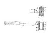
- a space-maintainer for inserting between two vertebral bodiescomprises a sleeve-shaped first part ( 1 ) and a second part ( 2 ) guided therein and displaceable in the axial direction relative to the first part, which are both ( 1 , 2 ) connected to one another by a device which transforms a rotary movement acting from outside into a movement displacing the carts ( 1 , 2 ) in their relative longitudinal position, wherein one of the parts has a toothed profile ( 22 ) extending parallel to the longitudinal axis of the parts and the other part has a toothed wheel ( 24 ) located in engagement with the toothed profile ( 22 ) for adjusting a total length.
- FIG. 1shows a side view of the space-maintainer.
- FIG. 2shows a section along the line A—A.
- FIG. 3shows a detail from FIG. 2 .
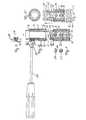
- FIG. 4shows the side view as in FIG. 1 in an expanded state.
- FIG. 5shows a horizontal projection on to the device shown in FIG. 4 .
- the outer sleeve 1has a first casing section 3 , extending from the first open end 4 over more than half the sleeve toward its other end.
- This casing sectionhas a first inner diameter.
- the casingis fashioned as thinner on the inside and has a second inner diameter which is larger than the first inner diameter.
- the first casing sectionhas a plurality of recesses 8 , distributed over the entire casing section, in the form of bores extending through the casing.
- the second casing section 5in the way seen in FIG. 1 , has rhomboidal recesses 10 , 11 , extending with their longitudinal diagonal parallel to the casing axis 9 .
- a first group of these rhomboidal recesses 10extends in the circumferential direction and, adjoining them, directed towards the first open end 4 a second group 11 , wherein the second group is offset from the first group in the axial direction by half the height of a rhombus.
- a network of flat strips 12 , 13intersecting one another at an acute angle, is formed, inclined at angles of identical size in each case against the longitudinal diagonal of the rhombi.
- the size of the rhombi and the flat strips bordering on theseis chosen in such a way that the number of rhombi is always a whole number in the circumferential direction.
- the thus formed edgetherefore has prongs formed by the flat strips and indentations 22 in between.
- the sleeve-shaped second part 2has a casing section 15 , adjoining its first open end 14 , with a first outer diameter.
- This casing sectionextends in the embodiment example shown over slightly more than two thirds of the axial length.
- the outer diameteris chosen in such a way that the inner sleeve 2 is contained so as to slide in the first casing portion 3 of the outer sleeve 1 .
- the inner sleeveOn the first open end 14 the inner sleeve has an edge 17 , the diameter of which is larger than the diameter of the first casing section and larger than the first inner diameter of the outer sleeve and smaller than the inner diameter of the second casing section 5 of the outer sleeve.
- the first casing section 15has in a direction parallel to the casing axis 9 a plurality of indentations 18 shaped like ball segments, directly bordering on one another, the depth of which is smaller than their radius.
- the distance in each case between two adjacent indentationsis smaller than the diameter of the edge of the indentations shaped like ball segments bordering the indentation. It is therein achieved that the border 19 between two adjacent indentations is lower than the actual edge of the indentations themselves.
- the area of the indentations 18extends over almost the entire length of the first casing section 15 .
- first casing sectionby analogy to the recesses 8 , are arranged recesses 21 , also extending over the entire surface of the casing section and formed as bores going through the casing.
- the second casing section 16is constructed analogously to the second casing section 5 of the first sleeve and has rhomboidal recesses 10 , 11 arranged in the same way, with the bands 12 , 13 in between.
- the bandsare constructed as running crosswise to one another on the open end of the sleeve and in each case enclose indentations 22 with relatively sharp edges projecting in between.
- the wall of the inner second part 2has a toothed profile 22 , extending parallel to the longitudinal axis 9 , which is formed in the wall in such a way that a row of teeth emerges as with a toothed rack.
- the outer sleeve 1has in the first casing section 3 a bore 23 , which acts as pivot bearing.
- a toothed wheel 24which has a shaft 25 on one of its sides. The shaft 25 is dimensioned in such a way that it is carried in the bore 23 so as to slide.
- the bore 23is arranged in the circumferential direction in such a way that the toothed wheel 24 carried therein is in engagement with the toothed profile 22 in the way seen best in FIGS. 1 and 4 .
- the radius of the toothed wheel 24is chosen in such a way that the centre of the toothed wheel carried in the bore 23 on engagement with the toothed profile 22 is located precisely on the centre line of the indentations 18 .
- the bore 23is attached close to the first open end 4 of the outer sleeve 1 , wherein, however, the distance from the open end is at least equal to the diameter of the toothed wheel.
- the outer sleeve 1has a thread bore 26 .
- a fixing screw 27shown in FIG. 1 at the bottom in horizontal projection and at the top in side view.
- the fixing screwhas an outer thread, corresponding to the inner thread of the bore 26 .
- a ball segment 28is provided on the front end of the fixing screw . The dimensions of the ball segment correspond to the greater depth of the indentations 18 .
- the shaft 25 of the toothed wheel 24has an orifice 29 at its open end, which is shaped in such a way that a correspondingly matched rotary instrument or screwing instrument can be inserted. Further provided is a kind of screwdriver 30 , which has a projection 31 on its front face corresponding to the shape of the orifice 29 .
- the space-maintaineris first inserted in the telescoped way shown in FIG. 2 between two adjacent vertebral bodies. Then, by insertion of the screwdriver 30 with its projection into the orifice 29 and rotating, expansion of the space-maintainer to a desired length takes place. After the length has been reached, the fixing screw 27 , which has possibly already been loosely inserted beforehand into the thread bore 26 , is tightened, so a stable connection is produced between the two sleeve parts 1 and 2 .
Landscapes
- Health & Medical Sciences (AREA)
- Orthopedic Medicine & Surgery (AREA)
- Engineering & Computer Science (AREA)
- Biomedical Technology (AREA)
- Heart & Thoracic Surgery (AREA)
- Cardiology (AREA)
- Oral & Maxillofacial Surgery (AREA)
- Transplantation (AREA)
- Neurology (AREA)
- Vascular Medicine (AREA)
- Life Sciences & Earth Sciences (AREA)
- Animal Behavior & Ethology (AREA)
- General Health & Medical Sciences (AREA)
- Public Health (AREA)
- Veterinary Medicine (AREA)
- Prostheses (AREA)
- Surgical Instruments (AREA)
Abstract
Description
Claims (7)
Applications Claiming Priority (2)
| Application Number | Priority Date | Filing Date | Title |
|---|---|---|---|
| DE10065398.7 | 2000-12-27 | ||
| DE10065398ADE10065398C2 (en) | 2000-12-27 | 2000-12-27 | Length-adjustable placeholder for insertion between two vertebrae |
Publications (2)
| Publication Number | Publication Date |
|---|---|
| US20020082696A1 US20020082696A1 (en) | 2002-06-27 |
| US6902579B2true US6902579B2 (en) | 2005-06-07 |
Family
ID=7669246
Family Applications (1)
| Application Number | Title | Priority Date | Filing Date |
|---|---|---|---|
| US10/034,545Expired - LifetimeUS6902579B2 (en) | 2000-12-27 | 2001-12-21 | Lengthwise adjustable space-maintainer for inserting between two vertebral bodies |
Country Status (3)
| Country | Link |
|---|---|
| US (1) | US6902579B2 (en) |
| CH (1) | CH695440A5 (en) |
| DE (1) | DE10065398C2 (en) |
Cited By (53)
| Publication number | Priority date | Publication date | Assignee | Title |
|---|---|---|---|---|
| US20040059271A1 (en)* | 2002-09-23 | 2004-03-25 | Sdgi Holdings, Inc. | Expansion tool for adjustable spinal implant |
| US20070073398A1 (en)* | 2005-09-27 | 2007-03-29 | Fabian Henry F | Spine surgery method and implant |
| US20070255415A1 (en)* | 2006-05-01 | 2007-11-01 | Sdgi Holdings, Inc. | Expandable intervertebral spacers and methods of use |
| US20070255413A1 (en)* | 2006-04-27 | 2007-11-01 | Sdgi Holdings, Inc. | Expandable intervertebral spacers and methods of use |
| US20080009946A1 (en)* | 2006-06-20 | 2008-01-10 | Stephane Douget | Distractible intervertebral implant |
| US20080178632A1 (en)* | 2007-01-29 | 2008-07-31 | Rudolph Hugo Petrmichl | Method of making heat treated coated article using diamond-like carbon (DLC) coating and protective film |
| US20090005816A1 (en)* | 2007-06-26 | 2009-01-01 | Denardo Andrew J | Spinal rod, insertion device, and method of using |
| US20090088833A1 (en)* | 2007-09-28 | 2009-04-02 | Maximiliano Soetermans | Double wall stent with retrieval member |
| US20090112324A1 (en)* | 2007-10-30 | 2009-04-30 | Biospine, Llc | Vertebral body replacement device and method for use to maintain a space between two vertebral bodies within a spine |
| US20090112325A1 (en)* | 2007-10-30 | 2009-04-30 | Biospine, Llc | Footplate member and a method for use in a vertebral body replacement device |
| US20090118765A1 (en)* | 2003-03-24 | 2009-05-07 | Richard Mueller | Expandable Corpectomy Device |
| US20090138083A1 (en)* | 2006-09-14 | 2009-05-28 | Ashok Biyani | Variable height vertebral body replacement implant |
| US7544208B1 (en) | 2004-05-03 | 2009-06-09 | Theken Spine, Llc | Adjustable corpectomy apparatus |
| US20090164018A1 (en)* | 2007-12-19 | 2009-06-25 | Robert Sommerich | Instruments For Expandable Corpectomy Spinal Fusion Cage |
| US20090164017A1 (en)* | 2007-12-19 | 2009-06-25 | Robert Sommerich | Expandable Corpectomy Spinal Fusion Cage |
| US20090270873A1 (en)* | 2008-04-24 | 2009-10-29 | Fabian Henry F | Spine surgery method and inserter |
| US20100010544A1 (en)* | 2005-02-22 | 2010-01-14 | Stryker Spine | Apparatus and method for dynamic vertebral stabilization |
| US20100100100A1 (en)* | 2008-10-16 | 2010-04-22 | Daniel Refai | Surgical instrument and method of use for inserting an implant between two bones |
| US20100179657A1 (en)* | 2009-01-14 | 2010-07-15 | Stout Medical Group, L.P. | Expandable support device and method of use |
| US20100211119A1 (en)* | 2009-02-19 | 2010-08-19 | Daniel Refai | Multi-functional surgical instrument and method of use for inserting an implant between two bones |
| US20100280616A1 (en)* | 2009-04-29 | 2010-11-04 | William Frasier | Minimally invasive corpectomy cage and instrument |
| US20100305707A1 (en)* | 2006-07-14 | 2010-12-02 | Biedermann Motech Gmbh | Spacer for insertion between two vertebrae |
| US20110015747A1 (en)* | 2008-03-07 | 2011-01-20 | Mcmanus Joshua | Expandable interbody spacer device |
| US8211178B2 (en) | 2009-06-18 | 2012-07-03 | Warsaw Orthopedic | Intervertebral implant with a pivoting end cap |
| US8377140B2 (en) | 2011-01-12 | 2013-02-19 | Ebi, Llc | Expandable spinal implant device |
| US20130053965A1 (en)* | 2010-04-26 | 2013-02-28 | Peter Metz-Stavenhagen | Spinal implants and related apparatus and methods |
| US8591587B2 (en) | 2007-10-30 | 2013-11-26 | Aesculap Implant Systems, Llc | Vertebral body replacement device and method for use to maintain a space between two vertebral bodies within a spine |
| US8721723B2 (en) | 2009-01-12 | 2014-05-13 | Globus Medical, Inc. | Expandable vertebral prosthesis |
| US8740980B2 (en) | 2011-01-27 | 2014-06-03 | Warsaw Orthopedic, Inc. | Expandable medical implant |
| US8992617B2 (en) | 2007-03-13 | 2015-03-31 | DePuy Synthes Products, LLC | Adjustable intervertebral implant |
| US20150245919A1 (en)* | 2012-10-24 | 2015-09-03 | Waldemar Link Gmbh & Co. Kg | Holder for a medical implant |
| US9138217B2 (en) | 2009-11-11 | 2015-09-22 | Nu Vasive, Inc. | Surgical access system and related methods |
| US9211193B2 (en) | 2013-08-30 | 2015-12-15 | Aesculap Implant Systems, Llc | Prosthesis, system and method |
| US9271843B2 (en) | 2005-09-27 | 2016-03-01 | Henry F. Fabian | Spine surgery method and implant |
| US9387090B2 (en) | 2009-03-12 | 2016-07-12 | Nuvasive, Inc. | Vertebral body replacement |
| US9474621B2 (en) | 2010-04-12 | 2016-10-25 | Globus Medical, Inc. | Expandable vertebral implant |
| US9566167B2 (en) | 2013-08-22 | 2017-02-14 | K2M, Inc. | Expandable spinal implant |
| US9687357B2 (en) | 2009-03-12 | 2017-06-27 | Nuvasive, Inc. | Vertebral body replacement |
| US9707091B2 (en) | 2010-04-12 | 2017-07-18 | Globus Medical, Inc. | Expandable vertebral implant |
| US9788960B2 (en) | 2011-04-26 | 2017-10-17 | Peter Metz-Stavenhagen | Spinal implants and related apparatus and methods |
| US10363142B2 (en) | 2014-12-11 | 2019-07-30 | K2M, Inc. | Expandable spinal implants |
| US10441430B2 (en) | 2017-07-24 | 2019-10-15 | K2M, Inc. | Expandable spinal implants |
| US10611679B2 (en) | 2017-10-26 | 2020-04-07 | Guardian Glass, LLC | Coated article including noble metal and polymeric hydrogenated diamond like carbon composite material having antibacterial and photocatalytic properties, and/or methods of making the same |
| US10881518B2 (en) | 2017-04-01 | 2021-01-05 | HD LifeSciences LLC | Anisotropic biocompatible lattice structure |
| US11253368B2 (en) | 2017-02-14 | 2022-02-22 | Nanohive Medical Llc | Methods of designing high x-ray lucency lattice structures |
| US11278424B2 (en) | 2016-11-28 | 2022-03-22 | Musc Foundaton For Research Development | Expandable vertebral body replacement device and method |
| US11291558B2 (en) | 2018-07-26 | 2022-04-05 | Nanohive Medical Llc | Dynamic implant fixation plate |
| US11426287B2 (en) | 2010-04-12 | 2022-08-30 | Globus Medical Inc. | Expandable vertebral implant |
| US11497617B2 (en) | 2019-01-16 | 2022-11-15 | Nanohive Medical Llc | Variable depth implants |
| US11602436B2 (en) | 2015-03-23 | 2023-03-14 | Musc Foundation For Research Development | Expandable vertebral body replacement device and method |
| US11883303B2 (en) | 2019-12-30 | 2024-01-30 | Vertebration, Inc. | Spine surgery method and instrumentation |
| US11931266B2 (en) | 2016-06-07 | 2024-03-19 | Nanohive Medical Llc | Implant with independent endplates |
| US12295858B2 (en) | 2020-02-24 | 2025-05-13 | Musc Foundation For Research Development | Expandable vertebral body replacement device and method |
Families Citing this family (10)
| Publication number | Priority date | Publication date | Assignee | Title |
|---|---|---|---|---|
| DE10065232C2 (en) | 2000-12-27 | 2002-11-14 | Ulrich Gmbh & Co Kg | Implant for insertion between the vertebral body and surgical instrument for handling the implant |
| WO2004052245A1 (en)* | 2002-12-06 | 2004-06-24 | Synthes Ag Chur | Intervertebral implant |
| FR2850563B1 (en)* | 2003-02-05 | 2005-11-04 | Scient X | VERTEBRAL REPLACEMENT IMPLANT AND DISTRACTION APPARATUS FOR IMPLANT PLACEMENT |
| DE102004021861A1 (en)* | 2004-05-04 | 2005-11-24 | Biedermann Motech Gmbh | Implant for temporary or permanent replacement of vertebra or intervertebral disk, comprising solid central element and outer elements with openings |
| DE102005061932A1 (en) | 2005-12-23 | 2007-07-05 | Biedermann Motech Gmbh | Placeholder for implantation to the human vertebrae has three tubular bodies having different lengths and diameters that are inserted and connected to each other by pins so that they project over the edges of the next larger tubular body |
| US8267939B2 (en) | 2008-02-28 | 2012-09-18 | Stryker Spine | Tool for implanting expandable intervertebral implant |
| EP2729092B1 (en) | 2011-08-16 | 2016-09-21 | Stryker European Holdings I, LLC | Expandable implant |
| US9572678B2 (en)* | 2012-02-07 | 2017-02-21 | Medivest, Llc | Tissue spacer implants, insertion and adjustment tools, and method of use |
| US10342675B2 (en) | 2013-03-11 | 2019-07-09 | Stryker European Holdings I, Llc | Expandable implant |
| WO2016077606A1 (en) | 2014-11-12 | 2016-05-19 | Medivest, Llc | Spinal spacing implant, spinal spacer assembly, expander and insertion instrument, kit and methods of assembly and use |
Citations (10)
| Publication number | Priority date | Publication date | Assignee | Title |
|---|---|---|---|---|
| DE9101603U1 (en) | 1991-02-12 | 1991-05-02 | Eska Medical Lübeck Medizintechnik GmbH & Co, 2400 Lübeck | Vertebral body implant |
| DE19622827A1 (en) | 1996-06-07 | 1997-12-11 | Ulrich Heinrich | Implant to be inserted between the vertebral body as a placeholder |
| US5702455A (en)* | 1996-07-03 | 1997-12-30 | Saggar; Rahul | Expandable prosthesis for spinal fusion |
| US5916267A (en)* | 1997-04-07 | 1999-06-29 | Arthit Sitiso | Anterior spinal implant system for vertebral body prosthesis |
| US5989290A (en)* | 1995-05-24 | 1999-11-23 | Biedermann; Lutz | Height-adjustable artificial vertebral body |
| WO2000023013A1 (en)* | 1998-10-15 | 2000-04-27 | Synthes Ag Chur | Telescopic vertebral prosthesis |
| US6176881B1 (en)* | 1997-04-15 | 2001-01-23 | Synthes | Telescopic vertebral prosthesis |
| US6193756B1 (en)* | 1997-09-30 | 2001-02-27 | Sulzer Orthopaedie Ag | Tubular support body for bridging two vertebrae |
| US6193755B1 (en)* | 1996-09-26 | 2001-02-27 | Howmedica Gmbh | Spinal cage assembly |
| US6200348B1 (en)* | 1998-02-06 | 2001-03-13 | Biedermann, Motech Gmbh | Spacer with adjustable axial length |
Family Cites Families (3)
| Publication number | Priority date | Publication date | Assignee | Title |
|---|---|---|---|---|
| CH627937A5 (en)* | 1977-11-17 | 1982-02-15 | Colpo Ltd | Device hand drill for treatment of dental root canal. |
| US5002546A (en)* | 1987-04-13 | 1991-03-26 | Romano Jack W | Curved bore drilling apparatus |
| DK166600B1 (en)* | 1991-01-17 | 1993-06-21 | Therkel Bisgaard | TOOL USE TOUCH BY SUTURING IN DEEP OPERATING OPENINGS OR BODY SPACES |
- 2000
- 2000-12-27DEDE10065398Apatent/DE10065398C2/ennot_activeExpired - Lifetime
- 2001
- 2001-12-14CHCH02290/01Apatent/CH695440A5/ennot_activeIP Right Cessation
- 2001-12-21USUS10/034,545patent/US6902579B2/ennot_activeExpired - Lifetime
Patent Citations (11)
| Publication number | Priority date | Publication date | Assignee | Title |
|---|---|---|---|---|
| DE9101603U1 (en) | 1991-02-12 | 1991-05-02 | Eska Medical Lübeck Medizintechnik GmbH & Co, 2400 Lübeck | Vertebral body implant |
| US5989290A (en)* | 1995-05-24 | 1999-11-23 | Biedermann; Lutz | Height-adjustable artificial vertebral body |
| DE19622827A1 (en) | 1996-06-07 | 1997-12-11 | Ulrich Heinrich | Implant to be inserted between the vertebral body as a placeholder |
| US5702455A (en)* | 1996-07-03 | 1997-12-30 | Saggar; Rahul | Expandable prosthesis for spinal fusion |
| US6193755B1 (en)* | 1996-09-26 | 2001-02-27 | Howmedica Gmbh | Spinal cage assembly |
| US5916267A (en)* | 1997-04-07 | 1999-06-29 | Arthit Sitiso | Anterior spinal implant system for vertebral body prosthesis |
| US6176881B1 (en)* | 1997-04-15 | 2001-01-23 | Synthes | Telescopic vertebral prosthesis |
| US6193756B1 (en)* | 1997-09-30 | 2001-02-27 | Sulzer Orthopaedie Ag | Tubular support body for bridging two vertebrae |
| US6200348B1 (en)* | 1998-02-06 | 2001-03-13 | Biedermann, Motech Gmbh | Spacer with adjustable axial length |
| WO2000023013A1 (en)* | 1998-10-15 | 2000-04-27 | Synthes Ag Chur | Telescopic vertebral prosthesis |
| US6524341B2 (en)* | 1998-10-15 | 2003-02-25 | Synthes (Usa) | Telescopic vertebral prosthesis |
Cited By (121)
| Publication number | Priority date | Publication date | Assignee | Title |
|---|---|---|---|---|
| US20060084975A1 (en)* | 2002-09-23 | 2006-04-20 | Sdgi Holdings, Inc. | Expansion apparatus for adjustable spinal implant |
| US20040059271A1 (en)* | 2002-09-23 | 2004-03-25 | Sdgi Holdings, Inc. | Expansion tool for adjustable spinal implant |
| US20100016971A1 (en)* | 2002-09-23 | 2010-01-21 | Warsaw Orthopedic, Inc. | Adjustable Spinal Implant |
| US7608078B2 (en) | 2002-09-23 | 2009-10-27 | Warsaw Orthopedic, Inc. | Expansion apparatus for adjustable spinal implant |
| US7588573B2 (en)* | 2002-09-23 | 2009-09-15 | Warsaw Orthopedic, Inc. | Expansion tool for adjustable spinal implant |
| US20090118765A1 (en)* | 2003-03-24 | 2009-05-07 | Richard Mueller | Expandable Corpectomy Device |
| US7918876B2 (en) | 2003-03-24 | 2011-04-05 | Theken Spine, Llc | Spinal implant adjustment device |
| US8152851B2 (en) | 2003-03-24 | 2012-04-10 | Theken Spine, Llc | Expandable corpectomy device |
| US7544208B1 (en) | 2004-05-03 | 2009-06-09 | Theken Spine, Llc | Adjustable corpectomy apparatus |
| US8974499B2 (en)* | 2005-02-22 | 2015-03-10 | Stryker Spine | Apparatus and method for dynamic vertebral stabilization |
| US9949762B2 (en) | 2005-02-22 | 2018-04-24 | Stryker European Holdings I, Llc | Apparatus and method for dynamic vertebral stabilization |
| US9486244B2 (en)* | 2005-02-22 | 2016-11-08 | Stryker European Holdings I, Llc | Apparatus and method for dynamic vertebral stabilization |
| US20150173801A1 (en)* | 2005-02-22 | 2015-06-25 | Stryker European Holdings I, Llc | Apparatus and method for dynamic vertebral stabilization |
| US20100010544A1 (en)* | 2005-02-22 | 2010-01-14 | Stryker Spine | Apparatus and method for dynamic vertebral stabilization |
| US8236058B2 (en) | 2005-09-27 | 2012-08-07 | Fabian Henry F | Spine surgery method and implant |
| US8062373B2 (en) | 2005-09-27 | 2011-11-22 | Fabian Jr Henry F | Spine surgery method and motion preserving implant |
| US9271843B2 (en) | 2005-09-27 | 2016-03-01 | Henry F. Fabian | Spine surgery method and implant |
| US20070073398A1 (en)* | 2005-09-27 | 2007-03-29 | Fabian Henry F | Spine surgery method and implant |
| US20070255413A1 (en)* | 2006-04-27 | 2007-11-01 | Sdgi Holdings, Inc. | Expandable intervertebral spacers and methods of use |
| US7794501B2 (en) | 2006-04-27 | 2010-09-14 | Wasaw Orthopedic, Inc. | Expandable intervertebral spacers and methods of use |
| US8579979B2 (en) | 2006-05-01 | 2013-11-12 | Warsaw Orthopedic, Inc. | Expandable intervertebral spacers and methods of use |
| US7708779B2 (en) | 2006-05-01 | 2010-05-04 | Warsaw Orthopedic, Inc. | Expandable intervertebral spacers and methods of use |
| US20070255415A1 (en)* | 2006-05-01 | 2007-11-01 | Sdgi Holdings, Inc. | Expandable intervertebral spacers and methods of use |
| US20080009946A1 (en)* | 2006-06-20 | 2008-01-10 | Stephane Douget | Distractible intervertebral implant |
| US7887596B2 (en) | 2006-06-20 | 2011-02-15 | Zimmer Spine S.A.S. | Distractible intervertebral implant |
| US20100305707A1 (en)* | 2006-07-14 | 2010-12-02 | Biedermann Motech Gmbh | Spacer for insertion between two vertebrae |
| US8900308B2 (en) | 2006-07-14 | 2014-12-02 | Biedermann Technologies Gmbh & Co. Kg | Spacer for insertion between two vertebrae |
| US9744051B2 (en) | 2006-07-14 | 2017-08-29 | Biedermann Technologies Gmbh & Co. Kg | Spacer for insertion between two vertebrae |
| JP2013163032A (en)* | 2006-07-14 | 2013-08-22 | Biedermann Technologies Gmbh & Co Kg | Spacer for insertion between two vertebrae |
| US20090138083A1 (en)* | 2006-09-14 | 2009-05-28 | Ashok Biyani | Variable height vertebral body replacement implant |
| US8152852B2 (en)* | 2006-09-14 | 2012-04-10 | The University Of Toledo | Variable height vertebral body replacement implant |
| US20080178632A1 (en)* | 2007-01-29 | 2008-07-31 | Rudolph Hugo Petrmichl | Method of making heat treated coated article using diamond-like carbon (DLC) coating and protective film |
| US8992617B2 (en) | 2007-03-13 | 2015-03-31 | DePuy Synthes Products, LLC | Adjustable intervertebral implant |
| US20090005816A1 (en)* | 2007-06-26 | 2009-01-01 | Denardo Andrew J | Spinal rod, insertion device, and method of using |
| US20090088833A1 (en)* | 2007-09-28 | 2009-04-02 | Maximiliano Soetermans | Double wall stent with retrieval member |
| US9034046B2 (en) | 2007-10-30 | 2015-05-19 | Aesculap Implant Systems, Llc | Vertebral body replacement device and method for use to maintain a space between two vertebral bodies within a spine |
| US8690950B2 (en) | 2007-10-30 | 2014-04-08 | Aesculap Implant Systems, Llc | Vertebral body replacement device and method for use to maintain a space between two vertebral bodies within a spine |
| US10881527B2 (en) | 2007-10-30 | 2021-01-05 | Aesculap Implant Systems, Llc | Vertebral body replacement device and method for use to maintain a space between two vertebral bodies within a spine |
| US20090112324A1 (en)* | 2007-10-30 | 2009-04-30 | Biospine, Llc | Vertebral body replacement device and method for use to maintain a space between two vertebral bodies within a spine |
| US10201432B2 (en) | 2007-10-30 | 2019-02-12 | Aesculap Implant Systems, Llc | Vertebral body replacement device and method for use to maintain a space between two vertebral bodies within a spine |
| US10806595B2 (en) | 2007-10-30 | 2020-10-20 | Aesculap Implant Systems, Llc | Vertebral body replacement device and method for use to maintain a space between two vertebral bodies within a spine |
| US20090112325A1 (en)* | 2007-10-30 | 2009-04-30 | Biospine, Llc | Footplate member and a method for use in a vertebral body replacement device |
| US8591587B2 (en) | 2007-10-30 | 2013-11-26 | Aesculap Implant Systems, Llc | Vertebral body replacement device and method for use to maintain a space between two vertebral bodies within a spine |
| US8182537B2 (en) | 2007-10-30 | 2012-05-22 | Aesculap Implant Systems, Llc | Vertebral body replacement device and method for use to maintain a space between two vertebral bodies within a spine |
| US20090164018A1 (en)* | 2007-12-19 | 2009-06-25 | Robert Sommerich | Instruments For Expandable Corpectomy Spinal Fusion Cage |
| US20090164017A1 (en)* | 2007-12-19 | 2009-06-25 | Robert Sommerich | Expandable Corpectomy Spinal Fusion Cage |
| US8241294B2 (en) | 2007-12-19 | 2012-08-14 | Depuy Spine, Inc. | Instruments for expandable corpectomy spinal fusion cage |
| US8241363B2 (en) | 2007-12-19 | 2012-08-14 | Depuy Spine, Inc. | Expandable corpectomy spinal fusion cage |
| USRE46261E1 (en) | 2007-12-19 | 2017-01-03 | DePuy Synthes Products, Inc. | Instruments for expandable corpectomy spinal fusion cage |
| US9149364B2 (en) | 2008-03-07 | 2015-10-06 | DePuy Synthes Products, Inc. | Expandable interbody spacer device |
| US8574300B2 (en) | 2008-03-07 | 2013-11-05 | DePuy Synthes Products, LLC | Expandable interbody spacer device |
| US20110015747A1 (en)* | 2008-03-07 | 2011-01-20 | Mcmanus Joshua | Expandable interbody spacer device |
| US9844445B2 (en) | 2008-03-07 | 2017-12-19 | DePuy Synthes Products, Inc. | Expandable interbody spacer device |
| US8579977B2 (en) | 2008-04-24 | 2013-11-12 | Henry F. Fabian | Spine surgery method and inserter |
| US20090270873A1 (en)* | 2008-04-24 | 2009-10-29 | Fabian Henry F | Spine surgery method and inserter |
| US9421113B2 (en) | 2008-04-24 | 2016-08-23 | Henry F. Fabian | Spine surgery method and inserter |
| US20100100100A1 (en)* | 2008-10-16 | 2010-04-22 | Daniel Refai | Surgical instrument and method of use for inserting an implant between two bones |
| US8702719B2 (en)* | 2008-10-16 | 2014-04-22 | Aesculap Implant Systems, Llc | Surgical instrument and method of use for inserting an implant between two bones |
| US20120310293A1 (en)* | 2008-10-16 | 2012-12-06 | Aesculap Implant Systems, Llc. | Surgical instrument and method of use for inserting an implant between two bones |
| US8142441B2 (en)* | 2008-10-16 | 2012-03-27 | Aesculap Implant Systems, Llc | Surgical instrument and method of use for inserting an implant between two bones |
| US10314717B2 (en) | 2009-01-12 | 2019-06-11 | Globus Medical, Inc. | Expandable vertebral prosthesis |
| US9962268B2 (en) | 2009-01-12 | 2018-05-08 | Globus Medical, Inc. | Expandable vertebral prosthesis |
| US12220324B2 (en) | 2009-01-12 | 2025-02-11 | Globus Medical, Inc. | Expandable vertebral prosthesis |
| US11399951B2 (en) | 2009-01-12 | 2022-08-02 | Globus Medical, Inc. | Expandable vertebral prosthesis |
| US8721723B2 (en) | 2009-01-12 | 2014-05-13 | Globus Medical, Inc. | Expandable vertebral prosthesis |
| US20100179657A1 (en)* | 2009-01-14 | 2010-07-15 | Stout Medical Group, L.P. | Expandable support device and method of use |
| US8252054B2 (en) | 2009-01-14 | 2012-08-28 | Stout Medical Group, L.P. | Expandable support device and method of use |
| US8142435B2 (en) | 2009-02-19 | 2012-03-27 | Aesculap Implant Systems, Llc | Multi-functional surgical instrument and method of use for inserting an implant between two bones |
| US20100211119A1 (en)* | 2009-02-19 | 2010-08-19 | Daniel Refai | Multi-functional surgical instrument and method of use for inserting an implant between two bones |
| US9636233B2 (en) | 2009-03-12 | 2017-05-02 | Nuvasive, Inc. | Vertebral body replacement |
| US10390960B2 (en) | 2009-03-12 | 2019-08-27 | Nuvasive, Inc. | Vertebral body replacement |
| US11458025B2 (en) | 2009-03-12 | 2022-10-04 | Nuvasive, Inc. | Vertebral body replacement |
| US11712344B2 (en) | 2009-03-12 | 2023-08-01 | Nuvasive, Inc. | Vertebral body replacement |
| US9687357B2 (en) | 2009-03-12 | 2017-06-27 | Nuvasive, Inc. | Vertebral body replacement |
| US12350169B2 (en) | 2009-03-12 | 2025-07-08 | Nuvasive, Inc. | Vertebral body replacement |
| US10413421B2 (en) | 2009-03-12 | 2019-09-17 | Nuvasive, Inc. | Vertebral body replacement |
| US9387090B2 (en) | 2009-03-12 | 2016-07-12 | Nuvasive, Inc. | Vertebral body replacement |
| US20100280616A1 (en)* | 2009-04-29 | 2010-11-04 | William Frasier | Minimally invasive corpectomy cage and instrument |
| US8876905B2 (en) | 2009-04-29 | 2014-11-04 | DePuy Synthes Products, LLC | Minimally invasive corpectomy cage and instrument |
| US8211178B2 (en) | 2009-06-18 | 2012-07-03 | Warsaw Orthopedic | Intervertebral implant with a pivoting end cap |
| US9138217B2 (en) | 2009-11-11 | 2015-09-22 | Nu Vasive, Inc. | Surgical access system and related methods |
| US9707091B2 (en) | 2010-04-12 | 2017-07-18 | Globus Medical, Inc. | Expandable vertebral implant |
| US9579211B2 (en) | 2010-04-12 | 2017-02-28 | Globus Medical, Inc. | Expandable vertebral implant |
| US11426287B2 (en) | 2010-04-12 | 2022-08-30 | Globus Medical Inc. | Expandable vertebral implant |
| US10369000B2 (en) | 2010-04-12 | 2019-08-06 | Globus Medical, Inc. | Expandable vertebral implant |
| US9474621B2 (en) | 2010-04-12 | 2016-10-25 | Globus Medical, Inc. | Expandable vertebral implant |
| US20130053965A1 (en)* | 2010-04-26 | 2013-02-28 | Peter Metz-Stavenhagen | Spinal implants and related apparatus and methods |
| US10166111B2 (en)* | 2010-04-26 | 2019-01-01 | Peter Metz-Stavenhagen | Spinal implants and related apparatus and methods |
| US9050195B2 (en) | 2011-01-12 | 2015-06-09 | Ebi, Llc | Expandable spinal implant device |
| US8377140B2 (en) | 2011-01-12 | 2013-02-19 | Ebi, Llc | Expandable spinal implant device |
| US8801788B2 (en) | 2011-01-27 | 2014-08-12 | Warsaw Orthopedic, Inc. | Expandable medical implant |
| US8740980B2 (en) | 2011-01-27 | 2014-06-03 | Warsaw Orthopedic, Inc. | Expandable medical implant |
| US9788960B2 (en) | 2011-04-26 | 2017-10-17 | Peter Metz-Stavenhagen | Spinal implants and related apparatus and methods |
| US20150245919A1 (en)* | 2012-10-24 | 2015-09-03 | Waldemar Link Gmbh & Co. Kg | Holder for a medical implant |
| US9526631B2 (en)* | 2012-10-24 | 2016-12-27 | Waldemar Link Gmbh & Co. Kg | Holder for a medical implant |
| US9566167B2 (en) | 2013-08-22 | 2017-02-14 | K2M, Inc. | Expandable spinal implant |
| US9211193B2 (en) | 2013-08-30 | 2015-12-15 | Aesculap Implant Systems, Llc | Prosthesis, system and method |
| US11331200B2 (en) | 2014-12-11 | 2022-05-17 | K2M, Inc. | Expandable spinal implants |
| US12257159B2 (en) | 2014-12-11 | 2025-03-25 | K2M, Inc. | Expandable spinal implants |
| US10363142B2 (en) | 2014-12-11 | 2019-07-30 | K2M, Inc. | Expandable spinal implants |
| US12239545B2 (en) | 2015-03-23 | 2025-03-04 | Musc Foundation For Research Development | Expandable vertebral body replacement device and method |
| US11602436B2 (en) | 2015-03-23 | 2023-03-14 | Musc Foundation For Research Development | Expandable vertebral body replacement device and method |
| US11931266B2 (en) | 2016-06-07 | 2024-03-19 | Nanohive Medical Llc | Implant with independent endplates |
| US11278424B2 (en) | 2016-11-28 | 2022-03-22 | Musc Foundaton For Research Development | Expandable vertebral body replacement device and method |
| US11253368B2 (en) | 2017-02-14 | 2022-02-22 | Nanohive Medical Llc | Methods of designing high x-ray lucency lattice structures |
| US11992408B2 (en) | 2017-02-14 | 2024-05-28 | Nanohive Medical Llc | Methods of designing high x-ray lucency lattice structures |
| US10888429B2 (en) | 2017-04-01 | 2021-01-12 | HD LifeSciences LLC | Three-dimensional lattice structures for implants |
| US20250099249A1 (en)* | 2017-04-01 | 2025-03-27 | Nanohive Medical Llc | Methods of designing three-dimensional lattice structures for implants |
| US11648124B2 (en) | 2017-04-01 | 2023-05-16 | Nanohive Medical Llc | Methods of designing three-dimensional lattice structures for implants |
| US12036126B2 (en) | 2017-04-01 | 2024-07-16 | Nanohive Medical Llc | Three-dimensional lattice structures for implants |
| US11806240B2 (en) | 2017-04-01 | 2023-11-07 | Nanohive Medical Llc | Three-dimensional lattice structures for implants |
| US10881518B2 (en) | 2017-04-01 | 2021-01-05 | HD LifeSciences LLC | Anisotropic biocompatible lattice structure |
| US12102539B2 (en) | 2017-04-01 | 2024-10-01 | Nanohive Medical Llc | Methods of designing three-dimensional lattice structures for implants |
| US10441430B2 (en) | 2017-07-24 | 2019-10-15 | K2M, Inc. | Expandable spinal implants |
| US12029662B2 (en) | 2017-07-24 | 2024-07-09 | K2M, Inc. | Expandable spinal implants |
| US11291552B2 (en) | 2017-07-24 | 2022-04-05 | K2M, Inc. | Expandable spinal implants |
| US10611679B2 (en) | 2017-10-26 | 2020-04-07 | Guardian Glass, LLC | Coated article including noble metal and polymeric hydrogenated diamond like carbon composite material having antibacterial and photocatalytic properties, and/or methods of making the same |
| US11291558B2 (en) | 2018-07-26 | 2022-04-05 | Nanohive Medical Llc | Dynamic implant fixation plate |
| US11497617B2 (en) | 2019-01-16 | 2022-11-15 | Nanohive Medical Llc | Variable depth implants |
| US11883303B2 (en) | 2019-12-30 | 2024-01-30 | Vertebration, Inc. | Spine surgery method and instrumentation |
| US12295858B2 (en) | 2020-02-24 | 2025-05-13 | Musc Foundation For Research Development | Expandable vertebral body replacement device and method |
Also Published As
| Publication number | Publication date |
|---|---|
| DE10065398C2 (en) | 2002-11-14 |
| DE10065398A1 (en) | 2002-07-18 |
| US20020082696A1 (en) | 2002-06-27 |
| CH695440A5 (en) | 2006-05-31 |
Similar Documents
| Publication | Publication Date | Title |
|---|---|---|
| US6902579B2 (en) | Lengthwise adjustable space-maintainer for inserting between two vertebral bodies | |
| US6200348B1 (en) | Spacer with adjustable axial length | |
| CA2455339C (en) | Extendable spinal implant and extension tool | |
| US6352556B1 (en) | Vertebral column replacement body | |
| CA2319675C (en) | Implant for replacing a vertebra | |
| KR100532548B1 (en) | An expandable osteosynthesis cage | |
| DE4302397C2 (en) | Artificial vertebral spacer | |
| EP0904751B1 (en) | Tubular support body for bridging two vertebrae | |
| US6176882B1 (en) | Intervertebral implant | |
| US9125701B2 (en) | Subtalar implant | |
| US5658284A (en) | Connection member for the connection of a resilient rod with a bone screw which can be anchored in a vertebra | |
| US20040049271A1 (en) | Spacer having a variable axial length | |
| US20080114371A1 (en) | Instrument for placement and distraction of an implant | |
| CN1122504C (en) | Height Adjustable Vertebral Body Surrogates | |
| KR20140025322A (en) | Angle-variable bone screw fixation arrangement | |
| KR960030899A (en) | Spacer implants to replace missing vertebrae | |
| US20020082602A1 (en) | Fixing element | |
| EP0365477B1 (en) | Expanding anchor | |
| KR20060063950A (en) | Bone plate | |
| US20100160916A1 (en) | Cuttting device | |
| US6340277B1 (en) | Self-tapping screw | |
| JPH078505A (en) | Vertebra joint | |
| JP2007506459A (en) | Braking element | |
| KR100498076B1 (en) | Telescoping device | |
| DE102012001131A1 (en) | Fastening system and method for its attachment in a facade panel |
Legal Events
| Date | Code | Title | Description |
|---|---|---|---|
| AS | Assignment | Owner name:BIEDERMANN MOTECH GMBH, GERMANY Free format text:ASSIGNMENT OF ASSIGNORS INTEREST;ASSIGNORS:HARMS, JURGEN;BIEDERMANN, LUTZ;OSTERMANN, PETER;REEL/FRAME:012448/0761;SIGNING DATES FROM 20011106 TO 20011130 | |
| STCF | Information on status: patent grant | Free format text:PATENTED CASE | |
| CC | Certificate of correction | ||
| FEPP | Fee payment procedure | Free format text:PAYOR NUMBER ASSIGNED (ORIGINAL EVENT CODE: ASPN); ENTITY STATUS OF PATENT OWNER: LARGE ENTITY Free format text:PAYER NUMBER DE-ASSIGNED (ORIGINAL EVENT CODE: RMPN); ENTITY STATUS OF PATENT OWNER: LARGE ENTITY | |
| FPAY | Fee payment | Year of fee payment:4 | |
| AS | Assignment | Owner name:BIEDERMANN MOTECH GMBH & CO. KG, GERMANY Free format text:CHANGE OF LEGAL FORM;ASSIGNOR:BIEDERMANN MOTECH GMBH;REEL/FRAME:027603/0504 Effective date:20090720 | |
| AS | Assignment | Owner name:BIEDERMANN TECHNOLOGIES GMBH & CO. KG, GERMANY Free format text:ASSIGNMENT OF ASSIGNORS INTEREST;ASSIGNOR:BIEDERMANN MOTECH GMBH & CO. KG;REEL/FRAME:027873/0551 Effective date:20120308 | |
| FPAY | Fee payment | Year of fee payment:8 | |
| FPAY | Fee payment | Year of fee payment:12 |