US6902565B2 - Occipital plate and system for spinal stabilization - Google Patents
Occipital plate and system for spinal stabilizationDownload PDFInfo
- Publication number
- US6902565B2 US6902565B2US09/788,639US78863901AUS6902565B2US 6902565 B2US6902565 B2US 6902565B2US 78863901 AUS78863901 AUS 78863901AUS 6902565 B2US6902565 B2US 6902565B2
- Authority
- US
- United States
- Prior art keywords
- plate
- occipital
- occipital plate
- fixation system
- rod
- Prior art date
- Legal status (The legal status is an assumption and is not a legal conclusion. Google has not performed a legal analysis and makes no representation as to the accuracy of the status listed.)
- Expired - Lifetime, expires
Links
- 230000006641stabilisationEffects0.000titledescription3
- 238000011105stabilizationMethods0.000titledescription3
- 210000000988bone and boneAnatomy0.000claimsabstractdescription41
- 238000003780insertionMethods0.000claimsdescription3
- 230000037431insertionEffects0.000claimsdescription3
- 230000000717retained effectEffects0.000claimsdescription3
- 230000007423decreaseEffects0.000claims3
- 238000013016dampingMethods0.000claims1
- 230000000712assemblyEffects0.000description8
- 238000000429assemblyMethods0.000description8
- 238000005452bendingMethods0.000description5
- 230000004927fusionEffects0.000description4
- 229910052751metalInorganic materials0.000description4
- 239000002184metalSubstances0.000description4
- 238000000034methodMethods0.000description4
- RTAQQCXQSZGOHL-UHFFFAOYSA-NTitaniumChemical compound[Ti]RTAQQCXQSZGOHL-UHFFFAOYSA-N0.000description3
- 239000007943implantSubstances0.000description3
- 239000010936titaniumSubstances0.000description3
- 229910052719titaniumInorganic materials0.000description3
- 238000013461designMethods0.000description2
- 230000000694effectsEffects0.000description2
- 238000012986modificationMethods0.000description2
- 230000004048modificationEffects0.000description2
- 229910000831SteelInorganic materials0.000description1
- 238000011161developmentMethods0.000description1
- 230000018109developmental processEffects0.000description1
- 210000002532foramen magnumAnatomy0.000description1
- 125000001475halogen functional groupChemical group0.000description1
- 238000009434installationMethods0.000description1
- 210000003625skullAnatomy0.000description1
- 230000000087stabilizing effectEffects0.000description1
- 229910001220stainless steelInorganic materials0.000description1
- 239000010935stainless steelSubstances0.000description1
- 239000010959steelSubstances0.000description1
- 230000007704transitionEffects0.000description1
Images


Classifications
- A—HUMAN NECESSITIES
- A61—MEDICAL OR VETERINARY SCIENCE; HYGIENE
- A61B—DIAGNOSIS; SURGERY; IDENTIFICATION
- A61B17/00—Surgical instruments, devices or methods
- A61B17/56—Surgical instruments or methods for treatment of bones or joints; Devices specially adapted therefor
- A61B17/58—Surgical instruments or methods for treatment of bones or joints; Devices specially adapted therefor for osteosynthesis, e.g. bone plates, screws or setting implements
- A61B17/68—Internal fixation devices, including fasteners and spinal fixators, even if a part thereof projects from the skin
- A61B17/70—Spinal positioners or stabilisers, e.g. stabilisers comprising fluid filler in an implant
- A61B17/7055—Spinal positioners or stabilisers, e.g. stabilisers comprising fluid filler in an implant connected to sacrum, pelvis or skull
- A—HUMAN NECESSITIES
- A61—MEDICAL OR VETERINARY SCIENCE; HYGIENE
- A61B—DIAGNOSIS; SURGERY; IDENTIFICATION
- A61B17/00—Surgical instruments, devices or methods
- A61B17/56—Surgical instruments or methods for treatment of bones or joints; Devices specially adapted therefor
- A61B17/58—Surgical instruments or methods for treatment of bones or joints; Devices specially adapted therefor for osteosynthesis, e.g. bone plates, screws or setting implements
- A61B17/68—Internal fixation devices, including fasteners and spinal fixators, even if a part thereof projects from the skin
- A61B17/70—Spinal positioners or stabilisers, e.g. stabilisers comprising fluid filler in an implant
- A61B17/7001—Screws or hooks combined with longitudinal elements which do not contact vertebrae
- A61B17/7002—Longitudinal elements, e.g. rods
- A61B17/7011—Longitudinal element being non-straight, e.g. curved, angled or branched
- A—HUMAN NECESSITIES
- A61—MEDICAL OR VETERINARY SCIENCE; HYGIENE
- A61B—DIAGNOSIS; SURGERY; IDENTIFICATION
- A61B17/00—Surgical instruments, devices or methods
- A61B17/56—Surgical instruments or methods for treatment of bones or joints; Devices specially adapted therefor
- A61B17/58—Surgical instruments or methods for treatment of bones or joints; Devices specially adapted therefor for osteosynthesis, e.g. bone plates, screws or setting implements
- A61B17/68—Internal fixation devices, including fasteners and spinal fixators, even if a part thereof projects from the skin
- A61B17/80—Cortical plates, i.e. bone plates; Instruments for holding or positioning cortical plates, or for compressing bones attached to cortical plates
- A61B17/8033—Cortical plates, i.e. bone plates; Instruments for holding or positioning cortical plates, or for compressing bones attached to cortical plates having indirect contact with screw heads, or having contact with screw heads maintained with the aid of additional components, e.g. nuts, wedges or head covers
- A61B17/8047—Cortical plates, i.e. bone plates; Instruments for holding or positioning cortical plates, or for compressing bones attached to cortical plates having indirect contact with screw heads, or having contact with screw heads maintained with the aid of additional components, e.g. nuts, wedges or head covers wherein the additional element surrounds the screw head in the plate hole
- A—HUMAN NECESSITIES
- A61—MEDICAL OR VETERINARY SCIENCE; HYGIENE
- A61B—DIAGNOSIS; SURGERY; IDENTIFICATION
- A61B17/00—Surgical instruments, devices or methods
- A61B17/56—Surgical instruments or methods for treatment of bones or joints; Devices specially adapted therefor
- A61B17/58—Surgical instruments or methods for treatment of bones or joints; Devices specially adapted therefor for osteosynthesis, e.g. bone plates, screws or setting implements
- A61B17/68—Internal fixation devices, including fasteners and spinal fixators, even if a part thereof projects from the skin
- A61B17/80—Cortical plates, i.e. bone plates; Instruments for holding or positioning cortical plates, or for compressing bones attached to cortical plates
- A61B17/8085—Cortical plates, i.e. bone plates; Instruments for holding or positioning cortical plates, or for compressing bones attached to cortical plates with pliable or malleable elements or having a mesh-like structure, e.g. small strips
Definitions
- the present inventionis related to a system for stabilizing the spine. More particularly, the present invention is related to an occipitocervical fixation system that is mounted to both the occiput and spine.
- Occipitocervical fixationhas been achieved using a variety of techniques which generally provide stabilization of the base of the skull with respect to the neck.
- bone struts formed of autogenous ribs or curved iliac crest strutshave been fixed to the occiput and spinous processes, cervical laminae, or facets. Wires are used to fix the struts in place until bone fusion occurs.
- the thickness of the occiputvaries, however, and thus the occiput is typically wired in regions of greater thickness such as near the foramen magnum, at the nuchal line, and along the midline crest.
- Holesare drilled in the occiput to receive the wires that are also fed through holes in the struts.
- the strutsmay be weak prior to fusion, and additional orthosis is applied such as with a halo vest or other hard collar until the struts can provide acceptably strong immobilization.
- metal strutsmay be used.
- One metal implantis a stainless steel, U-shaped device known as a Steinman pin.
- the threaded pinis bent to match the contour of the occipitocervical region, and fixed to the occiput and cervical laminae or facets using wires.
- the pinis generally symmetrically disposed about the spine, with the sides of the “U” creating a central region in which a bone graft can be disposed and further wired to the pin.
- the pinWhen attached to the occiput and spine, the pin assumes an inverted-U configuration.
- Several holesare formed in the occiput so that the U-bend may be fixed in place.
- Additional metal implantsinclude grooved or roughened titanium rods, smooth steel rods in the form of a Hartshill rectangle or Ransford loop, a Cotrel-Dubousset rod screw plate, and titanium frames have been employed.
- the present inventionis related to an occipital plate that includes a Y-shaped plate portion having a front side and a back side, a central portion, two leg portions, and a plurality of bone screw holes in the central portion, the holes being configured and dimensioned to receive a bushing.
- the occipital platealso includes at least one clamping portion disposed on the front side proximate a free end of at least one of the leg portions, and the plate is bendable to conform to the an occiput.
- the central portionincludes an upper portion, a lower portion, and a grooved portion therebetween, the upper portion having one bone screw hole.
- the grooved portionis flexible to permit the upper portion to be disposed at an angle with respect to the lower portion.
- the leg portions and at least a portion of the central portionare disposed in nonparallel planes, and the planes may intersect at an angle of between about 160° and about 175°, and in one embodiment the planes intersect at an angle of about 170°.
- the clamping portionmay include a pivot member and a clamp plate, the clamp plate being pivotable about the pivot member.
- the clamp platemay further include a hole, the pivot member being received in the hole.
- the pivot memberalso may include a tapered portion with serrations, and the leg portion may further include a tapered hole with serrations, with the serrations of the tapered portion positively engaging the serrations of the tapered hole.
- the diameter of the tapered holeincreases from the back side to the front side, and the clamp plate is secured to the pivot member with a fastener.
- the leg portionadditionally includes a rod-receiving first recess and the clamping plate additionally includes a rod-receiving second recess, with the first and second recesses generally opposing each other and the second recess being serrated.
- the bone screw holes in the lower portionmay be disposed in a rectangular array, and at least one group of bone screw holes in the array may be disposed along a central axis of the plate extending between the leg portions.
- the bone screw hole in the upper portionmay be disposed on the central axis, and at least two bone screw holes may be disposed coaxially.
- the bushingspermit polyaxial angulation
- the plateis bendable along at least two generally parallel axes and/or at least two generally perpendicular axes.
- the present inventionis also related to an occipitocernical fixation system including an occipital plate having at least one rod clamp portion and a plate portion with at least one hole for receiving a bone screw, the rod clamp portion having a post, a clamp plate with a hole for receiving the post, and a fastener for tightening the clamp to the post.
- the systemalso includes at least one bone screw and at least one rod, with the rod being retained between the plate portion and the clamp plate and being pivotable about the post.
- the present inventionis related to a pre-bent rod for attachment to an occipital plate including a straight section, a bent section, and a serrated clamping section, with the straight section and the serrated clamping section being disposed substantially perpendicular to each other, and the serrated clamping section and the bent section being disposed at an angle of about 45° with respect to each other.
- the serrated clamping sectionis generally cylindrical and includes circumferential serrations about an angular range of between about 90° and 180°.
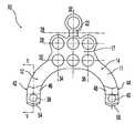
- FIG. 1shows a front view of an occipital plate according to the present invention
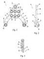
- FIG. 2shows a side view thereof
- FIG. 3shows a partial cross-sectional side view of a hole in the occipital plate of FIG. 1 taken along line III—III;
- FIG. 4shows another front view of the occipital plate of FIG. 1 without clamping plates attached thereto;
- FIGS. 4A-4Bshow front views of additional embodiments of occipital plates without clamping plates attached thereto;
- FIG. 5shows a partial cross-sectional side view of a leg portion of the occipital plate of FIG. 4 taken along line V—V;
- FIG. 6shows a partial front view of part of a leg portion of the occipital plate of FIG. 4 ;
- FIG. 7shows a side view of the occipital plate of FIG. 4 ;
- FIG. 8shows a post according to the present invention
- FIGS. 9 and 10show a side view and a partial cross-sectional side view, respectively, of the occipital plate of FIG. 7 with a post inserted therein;
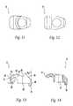
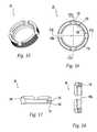
- FIGS. 11-14show a top view, bottom view, side view, and partial cross-sectional view, respectively, of a clamping plate according to the present invention
- FIGS. 15-18show a perspective view, top view, partial cross-sectional view through line XVII—XVII, and partial cross-sectional view through line XVIII—XVIII, respectively, of a bushing for use with the present invention
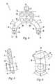
- FIGS. 19 and 19Ashow a front view of a first embodiment of a right prebent rod and a left pre-bent rod, respectively, according to the present invention
- FIG. 20shows a side view of the pre-bent rod of FIG. 19 ;
- FIG. 21shows a side view of the serrated clamping section of FIG. 20 ;
- FIGS. 22-23show a front view and a side view of a second embodiment of a pre-bent rod according to the present invention
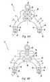
- FIG. 24shows an occipital plate with first and second embodiments of the pre-bent rods of FIGS. 19-23 ;
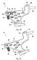
- FIGS. 25-26show a front view and a partial cross-sectional side view of another embodiment of an occipital plate according to the present invention.
- FIGS. 27-29show a front view side view, and partial cross-sectional side view of yet another embodiment of an occipital plate according to the present invention.
- FIGS. 30-31show perspective view of additional embodiments of occipital plates according to the present invention.
- occipital plate 10is generally Y-shaped with a pair of rod supporting arms 12 , 14 and a central extension 16 along with a main portion 17 .
- Holes 18extending from the front surface 11 to the back surface 13 are provided for receiving bone fasteners (not shown) for fixation of occipital plate 10 to the occiput.
- holes 18are each provided with an expansion head bushing 20 to permit relative angulation of a locking screw or other bone fastener received therein.
- a grooved region 22is provided along central extension 16 to facilitate bending of plate 10 .
- plate 10may be bent along grooved region 22 .
- central extension 16 and grooved region 22may be removed from plate 10 .
- grooved region 22has a thickness that may be accommodated in a rod cutter as used with the rods of the present invention.
- a clamp assembly 24 , 26is provided proximate the free end of each rod supporting arm 12 , 14 , respectively, for clamping a portion of a rod against occipital plate 10 .
- spinal rodsare positionable in clamp assemblies 24 , 26 , by insertion from the top portion 21 of the assemblies. Alternatively, the rods may be inserted from a side portion 23 of the assemblies.
- the preferred embodimentincludes two clamp assemblies, 24 , 26 , a number other than two may be provided.
- Rod supporting arms 12 , 14may also be bent, for example near points 12 ′, 14 ′.
- occipital plate 10includes seven fastener holes 18 , with six of the holes 18 aligned in a 2 ⁇ 3 rectangular array. Three holes 18 are aligned along line 28 while three holes 18 are aligned along line 30 , with lines 28 , 30 being parallel to each other. In addition, while three holes 18 are aligned along central line 32 , two holes are aligned long each of lines 34 , 26 . Lines 32 , 34 , 36 are parallel to each other and perpendicular to lines 28 , 30 . In addition, grooved region 22 is aligned along a line 38 which is parallel to lines 28 , 30 .
- occipital plate 10 ′includes four holes 18 that are disposed adjacent line 32 , such that the plate may be bent along line 32 without bending along holes 18 . In addition, this permits bone screws inserted in holes 18 to be angulated toward the midline 32 of the plate.
- occipital plate 10 ′′includes a triangular array of holes 18 with one hole along line 28 ′ and another hole along line 30 ′.
- occipital plate 10includes holes 38 , 40 in lower portions 42 , 44 respectively. Holes 38 , 40 are configured and dimensioned to receive clamping posts, as will be described.
- Rod-receiving recesses 46 , 48are generally V-shaped, with each leg of the “V” extending at an angle ⁇ with respect to a line 50 extending through V-notch 52 and the center of hole 40 , and further aligned parallel to lines 32 , 34 , 36 .
- angle ⁇ 1is between about 60° and about 80°, and more preferably about 70°.
- Arcuate stepped-in portions 54 , 56are disposed along the lowermost regions of rod supporting arms 12 , 14 , and preferably extend through a total angle of about 80° and about 120°, and more preferably about 100°, symmetrically with respect to line 50 . As shown in FIG. 5 , holes 38 , 40 are preferably tapered with a first diameter D 1 on front surface 11 being smaller than a second diameter D 2 on back surface 13 .
- central extension 16is disposed along a plane 60
- rod supporting arms 12 , 14are disposed along a plane 62 .
- Planes 60 , 62are not coplanar, and form an angle ⁇ 3 with respect to each other that is preferably between about 160° and about 175°, and more preferably about 170°.
- a post 64is shown.
- One post 64is placed in each hole 38 , 40 such that the tapered head 66 rests in the hole.
- taper head 66tapers at an angle ⁇ 4 of between about 5° and 15° and more preferably about 10° with respect to the central axis 70 of post 64 , and this taper angle is also present in holes 38 , 40 .
- a post 64 installed in a hole 38is shown in FIGS. 9-10 .
- head 66is provided with serrations that interlock with serrations on the inside surface of a hole 38 , 40 so that a positive mechanical engagement can be achieved to assist in locking a post 64 in place with respect to the occipital plate 10 .
- Post 64also includes a body portion 68 , which preferably is at least partially threaded for receiving a nut or other like-threaded fastening device.
- Clamp plate 72for use as a part of a clamp assembly 24 , 26 is shown.
- Clamp plate 72includes a hooked serrated portion 74 for engagement with a longitudinal rod, and further includes a central pivoting hole 76 in which a post 64 is received.
- a leg 78 of each clamp plate 72is received in an arcuate stepped-in portion 54 , 56 of a rod supporting arm 12 , 14 .
- Front edge 80 of clamp plate 72is disposed at an angle ⁇ 5 with respect to top edge 82 , and preferably angle ⁇ 5 is about 45°.
- Back edge 84is disposed at an angle ⁇ 6 with respect to rear edge 86 , and preferably angle ⁇ 6 is about 38°.
- Outer and inner sides 88 , 90are substantially parallel with respect to each other.
- Edge 92is disposed at an angle ⁇ 7 with respect to edge 93 , with angle ⁇ 7 preferably being about 22°.
- Bushing 20for use with the present invention is shown.
- Bushing 20has an upper surface 116 , a lower surface 118 , and a sidewall 120 .
- Sidewall 120has an exterior surface 122 configured and dimensioned for polyaxial rotation within a through hole 18 .
- a fastener inserted through a bore 124which is defined by an interior surface 126 of bushing 20 and extends through both upper and lower surfaces 116 , 118 , can be inserted at a wide variety of orientations relative to occipital plate 10 .
- bushing 20has a frustospherical shape.
- bushing 20can have a frustoconical shape. With either shape, bore 124 can extend through the central longitudinal axis perpendicular to the parallel upper and lower surfaces 116 , 118 .
- Bushing 20includes slots 128 located on sidewall 120 . Slots 128 allow sidewall 120 to expand outwardly against through hole 18 . This outward expansion locks bushing 20 at the selected orientation relative to the axis of through hole 18 . In order to enhance the locking effect upon expansion, exterior surface 122 of sidewall 120 and/or the periphery of through holes 18 can be provided with ridges 130 . Ridges 130 provide an additional mechanism to resist motion of bushing 20 relative to occipital plate 10 once sidewall 120 has expanded outwardly. Although bushing 20 is shown having four slots, any number of slots, including one, can be used as long as the chosen number of slots provides for outward expansion of sidewall 120 . Slot 128 a extends from upper surface 116 through lower surface 118 while the rest of slots 128 do not extend through to lower surface 118 . Slots 128 all extend from upper surface 116 of bushing 20 .
- pre-bent rods suitable for use with the present inventionare shown in FIGS. 19-21 .
- Each rod 140includes a straight section 142 for running generally parallel to the spine, a bent section 144 , and a serrated clamping section 146 .
- Sections 142 , 146are substantially perpendicular to each other, while sections 144 , 146 are disposed at an angle ⁇ 8 with respect to each other.
- angle ⁇ 8is between about 40° and about 50°, and more preferably approximately 45°.
- serrated clamping section 146includes serrations 148 about a portion of its circumference.
- serrations 148only extend through an angle ⁇ 9 from line 152 .
- angle ⁇ 9is between about 30° and about 50°, and more preferably about 41°.
- serrations 148are present along the circumference of section 146 of rod 148 through a total angular range ⁇ 10 as measured from center point 154 .
- ⁇ 10is between about 90° and 180°, and more preferably ⁇ 10 is about 156°.
- the pair of rods used with occipital plate 10are typically mirror images of each other.
- a rod 140would be used with right clamp assembly 26 while a mirror image of rod 140 , as shown in FIG. 19A , would be used with left clamp assembly 24 .
- pre-bent rod 160includes a straight section 162 for running generally parallel to the spine, a transition section 164 , and a serrated clamping section 166 .
- Sections 162 , 166are substantially perpendicular to each other, while sections 164 , 166 are disposed at an angle ⁇ 11 with respect to each other.
- angle ⁇ 11is between about 40° and about 50°, and more preferably approximately 45°.
- Pre-bent rods 140 , 160are shown retained in clamp assemblies 24 , 26 , respectively, in FIG. 24 .
- the pair of rods used with occipital plate 10are typically mirror images of each other, for illustrative purposes only, one of each rod 140 , 160 is shown.
- clamp plate 72rotates about post 64 , and may be fixed in place using a nut 168 .
- Rod receiving recesses 46 , 48are used to further lock a rod 140 , 160 in place.
- occipital platesare shown in FIGS. 25-31 .
- occipital plate 200includes seven holes 18 for receiving bone fasteners. However, in this embodiment, holes 18 are disposed about four parallel lines 202 , 204 , 206 , 208 instead of three.
- pre-bent rodsare clamped to occipital plate 200 using set screws 210 extending through a U-shaped or C-shaped section 216 , and which are disposed about an axis 212 that may be aligned with or slightly offset from the center of a rod held in region 214 .
- FIGS. 27-29Another embodiment is shown in FIGS. 27-29 , in which an occipital plate 250 is provided with nine holes 18 disposed about four parallel lines 254 , 256 , 258 , 260 . As with occipital plate 200 , sections 262 are provided for clamping spinal fixation rods to occipital plate 250 .
- a threaded set screw(not shown) is threadably received in like-threaded hole 264 , which is preferably aligned along an axis 266 disposed at an angle ⁇ 12 with respect to plate wall 268 .
- angle ⁇ 12is between about 50° and about 70°, and more preferably about 60°.
- threaded hole 264aligns a set screw to be offset from the center of a rod seated in region 270 and centered about point 272 .
- FIGS. 30-31Additional embodiments of occipital plates are shown in FIGS. 30-31 .
- expansion head screws 282are shown installed or partially installed in plate holes 18 .
- Occipital plates 280 , 300include notched regions 284 , 302 , respectively, to facilitate bending.
- side clamping assemblies 286 , 304receive rods 290 , 308 that are fixed with a set screw extending in holes 288 , 306 , respectively.
- side clamping assemblies 286 , 304are angulated such that rods 290 , 308 are disposed at an angle of between about 20° and about 30°, and more preferably about 25° with respect to the plane of the plate prior to bending.
- cylindrical rods with a diameter of 3.5 mmare used as the spinal rods or pre-bent rods.
- straight rodsmay be used and oriented accordingly by a surgeon using a rod bender.
- screw holeshave been positioned along the midline of the plate for use at the midline of the occiput, since the bone thickness there is greater than on the sides.
- the screw holesmay be angled about 12° to facilitate access to the screws with a screwdriver, and to enhance pull-out strength of the screws due to the wedge effect.
- expansion head screwsare preferred, other non-locking screws may be used.
- Arc shaped cuts between the clamping assemblies or arrangements of each plateallow the placement of a bone graft.
- occipital plate 10is formed of titanium.
- the shape of the occipital platefacilitates polyaxial bending thereof.
- the number of holes provided in an occipital plate of the present invention for receiving bone screwsmay be varied, as may the pattern of the holes and the relative alignment. Other screw hole shapes such as an oval shape, and other hole sizes may be used, as well as alternative means for locking screws. Bushings may not be included in some embodiments.
- Alternative fasteners for attaching an occipital plate to boneinclude staples and wires.
Landscapes
- Health & Medical Sciences (AREA)
- Orthopedic Medicine & Surgery (AREA)
- Surgery (AREA)
- Neurology (AREA)
- Life Sciences & Earth Sciences (AREA)
- Biomedical Technology (AREA)
- Nuclear Medicine, Radiotherapy & Molecular Imaging (AREA)
- Engineering & Computer Science (AREA)
- Heart & Thoracic Surgery (AREA)
- Medical Informatics (AREA)
- Molecular Biology (AREA)
- Animal Behavior & Ethology (AREA)
- General Health & Medical Sciences (AREA)
- Public Health (AREA)
- Veterinary Medicine (AREA)
- Neurosurgery (AREA)
- Surgical Instruments (AREA)
- Prostheses (AREA)
Abstract
Description
The present invention is related to a system for stabilizing the spine. More particularly, the present invention is related to an occipitocervical fixation system that is mounted to both the occiput and spine.
Occipitocervical fixation has been achieved using a variety of techniques which generally provide stabilization of the base of the skull with respect to the neck. In order to promote fusion, for example, bone struts formed of autogenous ribs or curved iliac crest struts have been fixed to the occiput and spinous processes, cervical laminae, or facets. Wires are used to fix the struts in place until bone fusion occurs. The thickness of the occiput varies, however, and thus the occiput is typically wired in regions of greater thickness such as near the foramen magnum, at the nuchal line, and along the midline crest. Holes are drilled in the occiput to receive the wires that are also fed through holes in the struts. Although bone fusion occurs with this technique, the struts may be weak prior to fusion, and additional orthosis is applied such as with a halo vest or other hard collar until the struts can provide acceptably strong immobilization. Alternatively, metal struts may be used.
Other techniques for occipitocervical fixation involve the use of other metal implants. One metal implant is a stainless steel, U-shaped device known as a Steinman pin. The threaded pin is bent to match the contour of the occipitocervical region, and fixed to the occiput and cervical laminae or facets using wires. The pin is generally symmetrically disposed about the spine, with the sides of the “U” creating a central region in which a bone graft can be disposed and further wired to the pin. When attached to the occiput and spine, the pin assumes an inverted-U configuration. Several holes are formed in the occiput so that the U-bend may be fixed in place.
Additional metal implants include grooved or roughened titanium rods, smooth steel rods in the form of a Hartshill rectangle or Ransford loop, a Cotrel-Dubousset rod screw plate, and titanium frames have been employed.
Despite these developments, there exists a need for an occipital plate and system for spinal stabilization in which the plate and rod components are separated to permit greater flexibility in installation by the surgeon. In particular, because a traditional unitary plate and rod system is bent in two planes in order to properly adjust it with respect to the occiput, such a unitary design presents difficulties in achieving the desired fit. devices Fixation is using wires that extend through holes formed in the occiput.
The present invention is related to an occipital plate that includes a Y-shaped plate portion having a front side and a back side, a central portion, two leg portions, and a plurality of bone screw holes in the central portion, the holes being configured and dimensioned to receive a bushing. The occipital plate also includes at least one clamping portion disposed on the front side proximate a free end of at least one of the leg portions, and the plate is bendable to conform to the an occiput. In one embodiment, the central portion includes an upper portion, a lower portion, and a grooved portion therebetween, the upper portion having one bone screw hole. The grooved portion is flexible to permit the upper portion to be disposed at an angle with respect to the lower portion. The leg portions and at least a portion of the central portion are disposed in nonparallel planes, and the planes may intersect at an angle of between about 160° and about 175°, and in one embodiment the planes intersect at an angle of about 170°.
The clamping portion may include a pivot member and a clamp plate, the clamp plate being pivotable about the pivot member. The clamp plate may further include a hole, the pivot member being received in the hole. The pivot member also may include a tapered portion with serrations, and the leg portion may further include a tapered hole with serrations, with the serrations of the tapered portion positively engaging the serrations of the tapered hole. The diameter of the tapered hole increases from the back side to the front side, and the clamp plate is secured to the pivot member with a fastener. The leg portion additionally includes a rod-receiving first recess and the clamping plate additionally includes a rod-receiving second recess, with the first and second recesses generally opposing each other and the second recess being serrated. The bone screw holes in the lower portion may be disposed in a rectangular array, and at least one group of bone screw holes in the array may be disposed along a central axis of the plate extending between the leg portions. The bone screw hole in the upper portion may be disposed on the central axis, and at least two bone screw holes may be disposed coaxially. In one embodiment, the bushings permit polyaxial angulation, the plate is bendable along at least two generally parallel axes and/or at least two generally perpendicular axes.
The present invention is also related to an occipitocernical fixation system including an occipital plate having at least one rod clamp portion and a plate portion with at least one hole for receiving a bone screw, the rod clamp portion having a post, a clamp plate with a hole for receiving the post, and a fastener for tightening the clamp to the post. The system also includes at least one bone screw and at least one rod, with the rod being retained between the plate portion and the clamp plate and being pivotable about the post.
Furthermore, the present invention is related to a pre-bent rod for attachment to an occipital plate including a straight section, a bent section, and a serrated clamping section, with the straight section and the serrated clamping section being disposed substantially perpendicular to each other, and the serrated clamping section and the bent section being disposed at an angle of about 45° with respect to each other. In one embodiment, the serrated clamping section is generally cylindrical and includes circumferential serrations about an angular range of between about 90° and 180°.
Preferred features of the present invention are disclosed in the accompanying drawings, wherein similar reference characters denote similar elements throughout the several views, and wherein:
Referring initially toFIGS. 1-3 , anoccipital plate 10 according to the present invention is shown. In the preferred embodiment,occipital plate 10 is generally Y-shaped with a pair ofrod supporting arms central extension 16 along with amain portion 17.Holes 18 extending from thefront surface 11 to theback surface 13 are provided for receiving bone fasteners (not shown) for fixation ofoccipital plate 10 to the occiput. Preferably, as shown inFIG. 3 , holes18 are each provided with anexpansion head bushing 20 to permit relative angulation of a locking screw or other bone fastener received therein. Agrooved region 22 is provided alongcentral extension 16 to facilitate bending ofplate 10. In the preferred embodiment,plate 10 may be bent along groovedregion 22. In an alternate embodiment,central extension 16 and groovedregion 22 may be removed fromplate 10. Preferably, groovedregion 22 has a thickness that may be accommodated in a rod cutter as used with the rods of the present invention. Aclamp assembly rod supporting arm occipital plate 10. Preferably, spinal rods are positionable inclamp assemblies top portion 21 of the assemblies. Alternatively, the rods may be inserted from aside portion 23 of the assemblies. In addition, although the preferred embodiment includes two clamp assemblies,24,26, a number other than two may be provided.Rod supporting arms points 12′,14′.
As shown inFIG. 4 , preferablyoccipital plate 10 includes sevenfastener holes 18, with six of theholes 18 aligned in a 2×3 rectangular array. Threeholes 18 are aligned alongline 28 while threeholes 18 are aligned alongline 30, withlines holes 18 are aligned alongcentral line 32, two holes are aligned long each oflines Lines lines region 22 is aligned along aline 38 which is parallel tolines
As shown inFIGS. 4A and 4B , additional hole patterns may be used with the occipital plates of the present invention. For example, inFIG. 4A ,occipital plate 10′ includes fourholes 18 that are disposedadjacent line 32, such that the plate may be bent alongline 32 without bending along holes18. In addition, this permits bone screws inserted inholes 18 to be angulated toward themidline 32 of the plate. InFIG. 4B ,occipital plate 10″ includes a triangular array ofholes 18 with one hole alongline 28′ and another hole alongline 30′.
Referring particularly toFIGS. 5-6 ,occipital plate 10 includesholes lower portions Holes recesses line 50 extending through V-notch 52 and the center ofhole 40, and further aligned parallel tolines portions rod supporting arms line 50. As shown inFIG. 5 , holes38,40 are preferably tapered with a first diameter D1onfront surface 11 being smaller than a second diameter D2onback surface 13.
With reference toFIG. 7 ,central extension 16 is disposed along aplane 60, whilerod supporting arms plane 62.Planes
Turning toFIGS. 8-10 , apost 64 is shown. Onepost 64 is placed in eachhole head 66 rests in the hole. Preferably,taper head 66 tapers at an angle θ4of between about 5° and 15° and more preferably about 10° with respect to thecentral axis 70 ofpost 64, and this taper angle is also present inholes post 64 installed in ahole 38 is shown inFIGS. 9-10 . Preferably,head 66 is provided with serrations that interlock with serrations on the inside surface of ahole post 64 in place with respect to theoccipital plate 10.Post 64 also includes abody portion 68, which preferably is at least partially threaded for receiving a nut or other like-threaded fastening device.
Referring toFIGS. 11-14 , aclamp plate 72 for use as a part of aclamp assembly Clamp plate 72 includes a hookedserrated portion 74 for engagement with a longitudinal rod, and further includes acentral pivoting hole 76 in which apost 64 is received. Aleg 78 of eachclamp plate 72 is received in an arcuate stepped-inportion rod supporting arm Front edge 80 ofclamp plate 72 is disposed at an angle θ5with respect totop edge 82, and preferably angle θ5is about 45°. Back edge84 is disposed at an angle θ6with respect torear edge 86, and preferably angle θ6is about 38°. Outer andinner sides Edge 92 is disposed at an angle θ7with respect to edge93, with angle θ7preferably being about 22°.
Turning briefly toFIGS. 15-18 , abushing 20 for use with the present invention is shown.Bushing 20 has anupper surface 116, alower surface 118, and asidewall 120.Sidewall 120 has anexterior surface 122 configured and dimensioned for polyaxial rotation within a throughhole 18. As a result and as described in more detail below, a fastener inserted through abore 124, which is defined by aninterior surface 126 ofbushing 20 and extends through both upper andlower surfaces occipital plate 10. In an exemplary embodiment, bushing20 has a frustospherical shape. Alternatively, bushing20 can have a frustoconical shape. With either shape, bore124 can extend through the central longitudinal axis perpendicular to the parallel upper andlower surfaces
In the preferred embodiment, pre-bent rods suitable for use with the present invention are shown inFIGS. 19-21 . Eachrod 140 includes astraight section 142 for running generally parallel to the spine, abent section 144, and aserrated clamping section 146.Sections sections FIG. 21 ,serrated clamping section 146 includesserrations 148 about a portion of its circumference. Whenbent section 144 is aligned withvertical line 150, andsection 146 is centered at the intersection ofperpendicular lines FIG. 21 thatserrations 148 only extend through an angle θ9fromline 152. Preferably, angle θ9is between about 30° and about 50°, and more preferably about 41°. Moreover,serrations 148 are present along the circumference ofsection 146 ofrod 148 through a total angular range θ10as measured fromcenter point 154. Preferably, θ10is between about 90° and 180°, and more preferably θ10is about 156°.
The pair of rods used withoccipital plate 10 are typically mirror images of each other. For example, arod 140 would be used withright clamp assembly 26 while a mirror image ofrod 140, as shown inFIG. 19A , would be used withleft clamp assembly 24.
In an alternate embodiment shown inFIGS. 22-23 ,pre-bent rod 160 includes astraight section 162 for running generally parallel to the spine, atransition section 164, and aserrated clamping section 166.Sections sections
Alternate embodiments of occipital plates are shown inFIGS. 25-31 . First referring toFIGS. 25-26 , similar tooccipital plate 10,occipital plate 200 includes sevenholes 18 for receiving bone fasteners. However, in this embodiment, holes18 are disposed about fourparallel lines FIG. 26 , pre-bent rods are clamped tooccipital plate 200 using setscrews 210 extending through a U-shaped or C-shapedsection 216, and which are disposed about anaxis 212 that may be aligned with or slightly offset from the center of a rod held inregion 214. Another embodiment is shown inFIGS. 27-29 , in which anoccipital plate 250 is provided with nineholes 18 disposed about fourparallel lines occipital plate 200,sections 262 are provided for clamping spinal fixation rods tooccipital plate 250. A threaded set screw (not shown) is threadably received in like-threadedhole 264, which is preferably aligned along anaxis 266 disposed at an angle θ12with respect toplate wall 268. Preferably, angle θ12is between about 50° and about 70°, and more preferably about 60°. Again, threadedhole 264 aligns a set screw to be offset from the center of a rod seated inregion 270 and centered aboutpoint 272.
Additional embodiments of occipital plates are shown inFIGS. 30-31 . Notably, expansion head screws282 are shown installed or partially installed in plate holes18.Occipital plates regions side clamping assemblies rods holes side clamping assemblies rods
In some preferred embodiments of the present invention, cylindrical rods with a diameter of 3.5 mm are used as the spinal rods or pre-bent rods. In alternate embodiments, straight rods may be used and oriented accordingly by a surgeon using a rod bender.
In the occipital plate designs disclosed herein, screw holes have been positioned along the midline of the plate for use at the midline of the occiput, since the bone thickness there is greater than on the sides. In some embodiments, the screw holes may be angled about 12° to facilitate access to the screws with a screwdriver, and to enhance pull-out strength of the screws due to the wedge effect. Although expansion head screws are preferred, other non-locking screws may be used. Arc shaped cuts between the clamping assemblies or arrangements of each plate allow the placement of a bone graft. In the preferred embodiment,occipital plate 10 is formed of titanium. Preferably, the shape of the occipital plate facilitates polyaxial bending thereof.
The number of holes provided in an occipital plate of the present invention for receiving bone screws may be varied, as may the pattern of the holes and the relative alignment. Other screw hole shapes such as an oval shape, and other hole sizes may be used, as well as alternative means for locking screws. Bushings may not be included in some embodiments. Alternative fasteners for attaching an occipital plate to bone include staples and wires.
While various descriptions of the present invention are described above, it should be understood that the various features can be used singly or in any combination thereof. Therefore, this invention is not to be limited to only the specifically preferred embodiments depicted herein.
Further, it should be understood that variations and modifications within the spirit and scope of the invention may occur to those skilled in the art to which the invention pertains. For example, the C-shaped clamping sections of some embodiments of the occipital plate may instead include full-circle regions for receiving rods. In another embodiment, a sleeve for receiving the rods may extend across some or the entire the length of the occipital plate. In yet another embodiment, two smaller occipital plates are provided for securement to the occiput, with each plate having a single clamp assembly and receiving one rod. Accordingly, all expedient modifications readily attainable by one versed in the art from the disclosure set forth herein that are within the scope and spirit of the present invention are to be included as further embodiments of the present invention. The scope of the present invention is accordingly defined as set forth in the appended claims.
Claims (69)
1. An occipital plate comprising:
a Y-shaped plate portion having a front side and a back side, a central portion, at least two leg portions, a plurality of bone screw holes in the central portion, and at least one bushing; wherein the holes are configured and dimensioned to receive the bushing; and
at least one clamping portion disposed on the front side proximate a free end of one of the at least two leg portions; wherein the clamping portion comprises a pivot member and a clamp plate, the clamp plate being pivotable about the pivot member and includes an extension sized and configured to engage an arcuate stepped-in portion formed on the leg portion of the plate to limit the amount of pivot between the clamp plate and the plate.
2. The occipital plate ofclaim 1 , wherein the central portion includes an upper portion, a lower portion, and a grooved portion therebetween, the upper portion having one bone screw hole.
3. The occipital plate ofclaim 2 , wherein the grooved portion is flexible to permit the upper portion to be disposed at an angle with respect to the lower portion.
4. The occipital plate ofclaim 2 , wherein the leg portions and at least a portion of the central portion are disposed in nonparallel planes.
5. The occipital plate ofclaim 4 , wherein the planes intersect at an angle of between about 160° and about 175°.
6. The occipital plate ofclaim 5 , wherein the planes intersect at an angle of about 170°.
7. The occipital plate ofclaim 1 , wherein the clamp plate further comprises a hole, the pivot member being received in the hole.
8. The occipital plate ofclaim 7 , wherein the pivot member further comprises a tapered portion with serrations, and the leg portion further comprises a tapered hole with serrations, wherein the serrations of the tapered portion positively engage the serrations of the tapered hole.
9. The occipital plate ofclaim 8 , wherein the diameter of the tapered hole decreases from the back side to the front side.
10. The occipital plate ofclaim 9 , wherein the clamp plate is secured to the pivot member a fastener.
11. The occipital plate ofclaim 1 , wherein the leg portion additionally comprises a rod-receiving first recess and the damping plate additionally comprises a rod-receiving second recess, the first and second recesses generally opposing each other.
12. The occipital plate ofclaim 11 , wherein the second recess is serrated.
13. The occipital plate ofclaim 2 , wherein the bone screw holes in the lower portion are disposed in a rectangular array.
14. The occipital plate ofclaim 13 , wherein at least one group of bone screw holes in the array is disposed along a central axis of the plate extending between the leg portions.
15. The occipital plate ofclaim 14 , wherein the bone screw hole in the upper portion is disposed on the central axis.
16. The occipital plate ofclaim 2 , wherein at least two bone screw holes are disposed coaxially.
17. The occipital plate ofclaim 1 , wherein the bushings permit polyaxial angulation.
18. The occipital plate ofclaim 1 , wherein the plate is bendable along at two generally parallel axes.
19. The occipital plate ofclaim 1 , wherein the plate is bendable along at least two generally perpendicular axes.
20. The occipital plate ofclaim 17 , wherein the exterior surface of the bushing has a frustospherical shape.
21. The occipital plate ofclaim 17 , wherein the bushing further includes at least one slot located on a sidewall thereof.
22. The occipital plate ofclaim 21 , wherein the sidewall further includes a ridge.
23. The occipital plate ofclaim 11 , wherein the rod-receiving first recess has a V-shaped recess.
24. An occipitocervical fixation system comprising:
an occipital plate comprising a plate portion with at least one hole for receiving a bone screw, and at least two rod clamp portions extending therefrom, at least one of the rod clamp portions having a post, a pivotable clamp plate with a hole for receiving the post, and a fastener for tightening the clamp plate to the post; and
at least one rod, wherein the rod is retained between the clamp plate and one of the rod clamp portions, the clamp plate being pivotable about the post,
wherein the plate further includes an arcuate stepped-in portion adjacent the post and the clamp plate further includes an extension sized and configured to engage the arcuate stepped-in portion.
25. The occipitocervical fixation system ofclaim 24 , wherein the arcuate stepped in-portion extends through an angle of about 80 degrees to about 120 degrees.
26. The occipitocervical fixation system ofclaim 24 , wherein the plate further includes a post hole sized and configured to receive the post.
27. The occipitocervical fixation system ofclaim 26 , wherein the post further comprises a tapered portion with serrations, and the post hole further comprises a tapered hole with serrations, wherein the serrations of the tapered portion positively engage the serrations of the tapered hole.
28. The occipitocervical fixation system ofclaim 27 , wherein the diameter of the tapered hole decreases from the back side to the front side.
29. The occipitocervical fixation system ofclaim 26 , wherein the plate further comprises a rod-receiving first recess and the clamp plate further comprises a rod-receiving second recess, the first and second recesses generally opposing each other.
30. The occipitocervical fixation system ofclaim 29 , wherein the second recess is serrated.
31. The occipitocervical fixation system ofclaim 29 , wherein the rod-receiving first recess has a V-shaped recess.
32. The occipitocervical fixation system ofclaim 24 , wherein the rod is positionable in one of the at least two clamp positions by insertion from a top portion of the assembly.
33. The occipitocervical fixation system ofclaim 24 , wherein the plate portion has an upper portion, a lower portion, and a grooved portion therebetween, the upper portion having one bone screw hole.
34. The occipitocervical fixation system ofclaim 33 , wherein the grooved portion is flexible to permit the upper portion to be disposed at an angle with respect to the lower portion.
35. The occipitocervical fixation system ofclaim 33 , wherein the bone screw holes in the lower portion are disposed in a rectangular array.
36. The occipitocervical fixation system ofclaim 35 , wherein at least one group of bone screw holes in the array is disposed along a central axis of the plate extending between the leg portions.
37. The occipitocervical fixation system ofclaim 36 , wherein the bone screw hole in the upper portion is disposed on the central axis.
38. The occipitocervical fixation system ofclaim 33 , wherein at least two bone screw holes are disposed coaxially.
39. The occipitocervical fixation system ofclaim 24 , wherein the rod clamp portion and the plate portion are disposed in nonparallel planes.
40. The occipitocervical fixation system ofclaim 39 , wherein the planes intersect at an angle of between about 160° and about 175°.
41. The occipitocervical fixation system ofclaim 39 , wherein the planes intersect at an angle of about 170°.
42. The occipitocervical fixation system ofclaim 24 , wherein the plate further includes a bushing; the at least one bone screw hole being sized and configured to receive the bushing to permit polyaxial angulation.
43. The occipitocervical fixation system ofclaim 42 , wherein the exterior surface of the bushing has a frustospherical shape.
44. The occipitocervical fixation system ofclaim 42 , wherein the bushing further includes at least one slot located on a sidewall thereof.
45. The occipitocervical fixation system ofclaim 44 , wherein the sidewall further includes a ridge.
46. The occipitocervical fixation system ofclaim 24 , wherein the plate is bendable along at least two generally parallel axes.
47. The occipitocervical fixation system ofclaim 24 , wherein the plate is bendable along at least two generally perpendicular axes.
48. An occipital plate comprising:
a front side and a back side, a central portion, and at least two leg portions extending from the central portion, at least one of the leg portions having a V-shaped rod-receiving first recess and an arcuate stepped-in portion;
at least one bone screw hole in the central portion;
at least one pivotable clamping portion disposed on the front side of one of the at least two leg portions;
wherein the at least one of the leg portions includes a post hole and the at least one clamping portion includes a pivot member and a clamp plate; the pivot member being sized and configured to mate with the clamp plate and the post hole and the clamp plate includes a rod-receiving second recess sized and configured to align with the V-shaped first recess and an extension sized and configured to engage the arcuate stepped-in portion.
49. The occipital plate ofclaim 48 , wherein the arcuate stepped in-portion extends through an angle of about 80 degrees to about 120 degrees.
50. The occipital plate ofclaim 48 , wherein the pivot member further comprises a tapered portion with serrations, and the post hole further comprises a tapered hole with serrations, wherein the serrations of the tapered portion positively engage the serrations of the tapered hole.
51. The occipital plate ofclaim 50 , wherein the diameter of the tapered hole decreases from the back side to the front side.
52. The occipital plate ofclaim 48 , wherein the clamp plate is secured to the pivot member with a fastener.
53. The occipital plate ofclaim 48 , wherein the second recess is serrated.
54. The occipital plate ofclaim 48 , wherein the plate further includes a spinal rod; the spinal rod being positionable in the at least one clamp portion by insertion from a top portion of the assembly.
55. The occipital plate ofclaim 48 , wherein the central portion includes an upper portion, a lower portion, and a grooved portion therebetween, the upper portion having one bone screw hole.
56. The occipital plate ofclaim 55 , wherein the grooved portion is flexible to permit the upper portion to be disposed at an angle with respect to the lower portion.
57. The occipital plate ofclaim 48 , wherein the leg portions and at least a portion of the central portion are disposed in nonparallel planes.
58. The occipital plate ofclaim 57 , wherein the planes intersect at an angle of between about 160° and about 175°.
59. The occipital plate ofclaim 57 , wherein the planes intersect at an angle of about 170°.
60. The occipital plate ofclaim 48 , wherein the bone screw holes, in the lower portion are disposed in a rectangular array.
61. The occipital plate ofclaim 60 , wherein at least one group of bone screw holes in the array is disposed along a central axis of the plate extending between the leg portions.
62. The occipital plate ofclaim 61 , wherein the bone screw hole in the upper portion is disposed on the central axis.
63. The occipital plate ofclaim 48 , wherein at least two bone screw holes are disposed coaxially.
64. The occipital plate ofclaim 48 , wherein the plate further includes a bushing; the at least one bone screw hole being sized and configured to receive the bushing to permit polyaxial angulation.
65. The occipital plate ofclaim 64 , wherein the exterior surface of the bushing has a frustospherical shape.
66. The occipital plate ofclaim 64 , wherein the bushing further includes at least one slot located on a sidewall thereof.
67. The occipital plate ofclaim 66 , wherein the sidewall further includes a ridge.
68. The occipital plate ofclaim 48 , wherein the plate is bendable along at least two generally parallel axes.
69. The occipital plate ofclaim 48 , wherein the plate is bendable along at least two generally perpendicular axes.
Priority Applications (17)
| Application Number | Priority Date | Filing Date | Title |
|---|---|---|---|
| US09/788,639US6902565B2 (en) | 2001-02-21 | 2001-02-21 | Occipital plate and system for spinal stabilization |
| PCT/US2002/005308WO2002067791A2 (en) | 2001-02-21 | 2002-02-19 | Occipital plate and system for spinal stabilization |
| AU2002247190AAU2002247190B2 (en) | 2001-02-21 | 2002-02-19 | Occipital plate and system for spinal stabilization |
| AT02714963TATE284648T1 (en) | 2001-02-21 | 2002-02-19 | OCCIPUT PLATE AND SYSTEM FOR STABILIZING THE SPINE |
| EP02714963AEP1372501B1 (en) | 2001-02-21 | 2002-02-19 | Occipital plate and system for spinal stabilization |
| JP2002567166AJP4202143B2 (en) | 2001-02-21 | 2002-02-19 | System for occipital plate and spine stabilization |
| DE60202267TDE60202267T2 (en) | 2001-02-21 | 2002-02-19 | Occipital plate and stabilization system for the spine |
| DK02714963TDK1372501T3 (en) | 2001-02-21 | 2002-02-19 | Occipital plate and system for stabilizing the spine |
| NZ527250ANZ527250A (en) | 2001-02-21 | 2002-02-19 | Occipital plate and system for spinal stabilization |
| BR0207472-9ABR0207472A (en) | 2001-02-21 | 2002-02-19 | Occipital plate, occipital plate fixation system and precurved nail for attachment to an occipital plate |
| MXPA03007509AMXPA03007509A (en) | 2001-02-21 | 2002-02-19 | Occipital plate and system for spinal stabilization. |
| CA002438861ACA2438861C (en) | 2001-02-21 | 2002-02-19 | Occipital plate and system for spinal stabilization |
| HK04101749.8AHK1061339B (en) | 2001-02-21 | 2002-02-19 | Occipital plate and system for spinal stabilization |
| PT02714963TPT1372501E (en) | 2001-02-21 | 2002-02-19 | OCCIPITAL PLATE AND SYSTEM FOR STABILIZACAODA VERTEBRAL COLUMN |
| ES02714963TES2231678T3 (en) | 2001-02-21 | 2002-02-19 | OCCIPITAL LAYER AND PPARA SYSTEM STABILIZATION OF THE RAQUIS. |
| ARP020100577AAR033864A1 (en) | 2001-02-21 | 2002-02-20 | OCCIPITAL PLATE FOR THE STABILIZATION OF THE VERTEBRAL COLUMN, OCCIPITOCERVICAL FIXING PROVISION THAT UNDERSTANDS IT AND PRECURVED VARILLA TO ATTACH THE PLATE. |
| US11/039,676US20050124994A1 (en) | 2001-02-21 | 2005-01-19 | Occipital plate and system for spinal stabilization |
Applications Claiming Priority (1)
| Application Number | Priority Date | Filing Date | Title |
|---|---|---|---|
| US09/788,639US6902565B2 (en) | 2001-02-21 | 2001-02-21 | Occipital plate and system for spinal stabilization |
Related Child Applications (1)
| Application Number | Title | Priority Date | Filing Date |
|---|---|---|---|
| US11/039,676ContinuationUS20050124994A1 (en) | 2001-02-21 | 2005-01-19 | Occipital plate and system for spinal stabilization |
Publications (2)
| Publication Number | Publication Date |
|---|---|
| US20020120268A1 US20020120268A1 (en) | 2002-08-29 |
| US6902565B2true US6902565B2 (en) | 2005-06-07 |
Family
ID=25145102
Family Applications (2)
| Application Number | Title | Priority Date | Filing Date |
|---|---|---|---|
| US09/788,639Expired - LifetimeUS6902565B2 (en) | 2001-02-21 | 2001-02-21 | Occipital plate and system for spinal stabilization |
| US11/039,676AbandonedUS20050124994A1 (en) | 2001-02-21 | 2005-01-19 | Occipital plate and system for spinal stabilization |
Family Applications After (1)
| Application Number | Title | Priority Date | Filing Date |
|---|---|---|---|
| US11/039,676AbandonedUS20050124994A1 (en) | 2001-02-21 | 2005-01-19 | Occipital plate and system for spinal stabilization |
Country Status (15)
| Country | Link |
|---|---|
| US (2) | US6902565B2 (en) |
| EP (1) | EP1372501B1 (en) |
| JP (1) | JP4202143B2 (en) |
| AR (1) | AR033864A1 (en) |
| AT (1) | ATE284648T1 (en) |
| AU (1) | AU2002247190B2 (en) |
| BR (1) | BR0207472A (en) |
| CA (1) | CA2438861C (en) |
| DE (1) | DE60202267T2 (en) |
| DK (1) | DK1372501T3 (en) |
| ES (1) | ES2231678T3 (en) |
| MX (1) | MXPA03007509A (en) |
| NZ (1) | NZ527250A (en) |
| PT (1) | PT1372501E (en) |
| WO (1) | WO2002067791A2 (en) |
Cited By (52)
| Publication number | Priority date | Publication date | Assignee | Title |
|---|---|---|---|---|
| US20030153913A1 (en)* | 2002-02-13 | 2003-08-14 | Moti Altarac | Occipital plate and rod system |
| US20060229610A1 (en)* | 2005-03-21 | 2006-10-12 | Zimmer Spine, Inc. | Variable geometry occipital fixation plate |
| US20060235399A1 (en)* | 2005-04-14 | 2006-10-19 | Sdgi Holdings, Inc. | Anti-backout mechanism for an implant fastener |
| US20070123869A1 (en)* | 2003-09-24 | 2007-05-31 | Spinefrontier Lls | Apparatus and method for spine fixation |
| US20070233119A1 (en)* | 2006-03-10 | 2007-10-04 | Markworth Aaron D | Polyaxial occipital plate |
| US20070299441A1 (en)* | 2006-06-09 | 2007-12-27 | Zachary M. Hoffman | Adjustable Occipital Plate |
| US20080051783A1 (en)* | 2006-08-02 | 2008-02-28 | Warsaw Orthopedic Inc. | Occipital plating systems and methods |
| US20080125781A1 (en)* | 2006-11-28 | 2008-05-29 | Zimmer Spine, Inc. | Adjustable occipital plate |
| US20080147123A1 (en)* | 2006-12-14 | 2008-06-19 | Seaspine, Inc. | Occipital plate assembly |
| US20080177314A1 (en)* | 2006-12-27 | 2008-07-24 | Jeremy Lemoine | Modular occipital plate |
| US20080177318A1 (en)* | 2007-01-18 | 2008-07-24 | Warsaw Orthopedic, Inc. | Vertebral Stabilizer |
| US20080177313A1 (en)* | 2006-12-27 | 2008-07-24 | Lemoine Jeremy J | Modular occipital plate |
| US20080234755A1 (en)* | 2007-01-29 | 2008-09-25 | Polaris Biotechnology, Inc. | Craniospinal fusion method and apparatus |
| US20090018584A1 (en)* | 2007-01-29 | 2009-01-15 | Polaris Biotechnology, Inc. | Vertebra attachment method and system |
| US20090036894A1 (en)* | 2007-01-29 | 2009-02-05 | Polaris Biotechnology, Inc. | Method of treating a neurological condition through correction and stabilization of the clivo-axial angle |
| US20090125067A1 (en)* | 2007-11-08 | 2009-05-14 | Depuy Spine, Inc. | In-line occipital plate and method of use |
| US20090177230A1 (en)* | 2008-01-08 | 2009-07-09 | Polaris Biotechnology, Inc. | Osteointegration apparatus |
| US20090264934A1 (en)* | 2008-04-22 | 2009-10-22 | Youssef Jim A | Bone plate system configurable as static or dynamic implant |
| US20100125299A1 (en)* | 2008-11-17 | 2010-05-20 | Warsaw Orthopedic, Inc. | Translational Occipital Vertebral Fixation System |
| US20100152575A1 (en)* | 2008-01-08 | 2010-06-17 | Polaris Biotechnology, Inc. | Mathematical Relationship of Strain, Neurological Dysfunction and Abnormal Behavior Resulting from Neurological Dysfunction of the Brainstem |
| US20100179597A1 (en)* | 2007-01-29 | 2010-07-15 | Polaris Biotechnology, Inc. | Craniospinal fusion method and apparatus |
| US7766911B1 (en) | 2002-07-05 | 2010-08-03 | Theken Spine, Llc | Fixed and variable locking fixation assembly |
| US7780706B2 (en) | 2005-04-27 | 2010-08-24 | Trinity Orthopedics, Llc | Mono-planar pedicle screw method, system and kit |
| US20100324557A1 (en)* | 2009-06-23 | 2010-12-23 | Aesculap Implant Systems, Inc. | Minimal access occipital plate |
| US20110028975A1 (en)* | 2009-07-29 | 2011-02-03 | Sean Suh | Clivus plate |
| US7901433B2 (en) | 2006-10-04 | 2011-03-08 | Zimmer Spine, Inc. | Occipito-cervical stabilization system and method |
| US20110106085A1 (en)* | 2009-10-30 | 2011-05-05 | Warsaw Orthopedic, Inc. | Adjustable occipital vertebral fixation system |
| US20110152932A1 (en)* | 2009-12-21 | 2011-06-23 | Industrial Technology Research Institute | Flexible Spine Fixing Structure |
| US20110160771A1 (en)* | 2009-12-31 | 2011-06-30 | Industrial Technology Research Institute | Flexible Spine Fixing Structure |
| US20110190824A1 (en)* | 2010-01-26 | 2011-08-04 | Gephart Matthew P | Occipital Plate for Spinal Fusion |
| US20120078309A1 (en)* | 2008-12-17 | 2012-03-29 | Lanx, Inc. | Modular vertebral stabilizer |
| US20120095466A1 (en)* | 2010-10-19 | 2012-04-19 | Biomet Manufacturing Corp. | Orthopedic Plate Assembly for a Distal Radius Having Re-Contouring Features and Method for Using Same |
| US20130030472A1 (en)* | 2005-05-03 | 2013-01-31 | Onike Technologies | Bone anchored surgical mesh |
| US8506567B2 (en) | 2009-02-04 | 2013-08-13 | Lanx, Inc. | Occipital plate fixation system |
| US20130253516A1 (en)* | 2012-03-23 | 2013-09-26 | John L Mackall | Occipital plate |
| US8702758B2 (en) | 2009-12-31 | 2014-04-22 | Industrial Technology Research Institute | Flexible spine fixing structure |
| US20140163617A1 (en)* | 2008-06-27 | 2014-06-12 | K2M, Inc. | System and method for performing spinal surgery |
| US20140200614A1 (en)* | 2001-07-20 | 2014-07-17 | Zimmer Spine, Inc. | Spinal stabilization system and method |
| US8992579B1 (en) | 2011-03-08 | 2015-03-31 | Nuvasive, Inc. | Lateral fixation constructs and related methods |
| US9060815B1 (en) | 2012-03-08 | 2015-06-23 | Nuvasive, Inc. | Systems and methods for performing spine surgery |
| US9060813B1 (en) | 2008-02-29 | 2015-06-23 | Nuvasive, Inc. | Surgical fixation system and related methods |
| US9381044B2 (en) | 2010-01-26 | 2016-07-05 | Pioneer Surgical Technology, Inc. | Posterior spinal stabilization plate device |
| US9387013B1 (en)* | 2011-03-01 | 2016-07-12 | Nuvasive, Inc. | Posterior cervical fixation system |
| US9480510B2 (en) | 2011-03-23 | 2016-11-01 | Spinecraft, LLC | Devices, systems and methods of attaching same to the spine |
| US9517089B1 (en) | 2013-10-08 | 2016-12-13 | Nuvasive, Inc. | Bone anchor with offset rod connector |
| US9526528B2 (en) | 2013-01-29 | 2016-12-27 | Chester Evan Sutterlin, III | Occipital and bone plate assemblies with mesh portions |
| US9827023B2 (en) | 2007-01-29 | 2017-11-28 | Life Spine, Inc. | Craniospinal fusion method and apparatus |
| US11039865B2 (en) | 2018-03-02 | 2021-06-22 | Stryker European Operations Limited | Bone plates and associated screws |
| US11298244B2 (en) | 2019-01-31 | 2022-04-12 | K2M, Inc. | Interbody implants and instrumentation |
| US11364055B2 (en) | 2020-09-02 | 2022-06-21 | Zavation, Llc | Occipital plate and hinged rod assembly |
| US11534307B2 (en) | 2019-09-16 | 2022-12-27 | K2M, Inc. | 3D printed cervical standalone implant |
| US11950811B2 (en) | 2020-09-22 | 2024-04-09 | Alphatec Spine, Inc. | Occipital plates and related methods |
Families Citing this family (82)
| Publication number | Priority date | Publication date | Assignee | Title |
|---|---|---|---|---|
| US6599290B2 (en) | 2001-04-17 | 2003-07-29 | Ebi, L.P. | Anterior cervical plating system and associated method |
| US6755833B1 (en) | 2001-12-14 | 2004-06-29 | Kamaljit S. Paul | Bone support assembly |
| US7070599B2 (en) | 2002-07-24 | 2006-07-04 | Paul Kamaljit S | Bone support assembly |
| US20040153338A1 (en)* | 2002-05-08 | 2004-08-05 | Back Kim | Medical information system |
| US7575588B2 (en)* | 2003-02-03 | 2009-08-18 | Warsaw Orthopedic Inc. | Midline occipital vertebral fixation system |
| US8172885B2 (en) | 2003-02-05 | 2012-05-08 | Pioneer Surgical Technology, Inc. | Bone plate system |
| JP4346358B2 (en)* | 2003-06-20 | 2009-10-21 | Necエレクトロニクス株式会社 | Chemically amplified resist composition, semiconductor device manufacturing method using the same, and pattern forming method |
| US7740649B2 (en) | 2004-02-26 | 2010-06-22 | Pioneer Surgical Technology, Inc. | Bone plate system and methods |
| US8900277B2 (en) | 2004-02-26 | 2014-12-02 | Pioneer Surgical Technology, Inc. | Bone plate system |
| US7942913B2 (en) | 2004-04-08 | 2011-05-17 | Ebi, Llc | Bone fixation device |
| US8241337B2 (en)* | 2004-05-25 | 2012-08-14 | Brockmeyer Douglas L | Occipitocervical plate |
| US7942912B2 (en)* | 2004-05-25 | 2011-05-17 | University Of Utah Research Foundation | Occipitocervical plate |
| EP1758511A4 (en)* | 2004-06-14 | 2008-12-03 | M S Abdou | Occipital fixation system and method of use |
| US20060082015A1 (en)* | 2004-09-30 | 2006-04-20 | Inion Ltd. | Surgical implant shaping instrument, surgical system and method |
| WO2006058221A2 (en) | 2004-11-24 | 2006-06-01 | Abdou Samy M | Devices and methods for inter-vertebral orthopedic device placement |
| US7527640B2 (en)* | 2004-12-22 | 2009-05-05 | Ebi, Llc | Bone fixation system |
| US20060229611A1 (en)* | 2005-03-30 | 2006-10-12 | Sdgi Holdings, Inc. | Spinal rod connector |
| US8177818B2 (en) | 2005-09-08 | 2012-05-15 | Securos, Inc. | Fixation plate |
| US7955364B2 (en)* | 2005-09-21 | 2011-06-07 | Ebi, Llc | Variable angle bone fixation assembly |
| JP4861422B2 (en)* | 2005-10-07 | 2012-01-25 | アルファテック スパイン, インコーポレイテッド | Adjustable occipital plate |
| KR101246113B1 (en)* | 2005-10-25 | 2013-03-20 | 앤썸 오르소패딕스, 엘엘씨 | Bone fastening assembly and bushing and screw for use therewith |
| US8100952B2 (en)* | 2005-12-22 | 2012-01-24 | Anthem Orthopaedics Llc | Drug delivering bone plate and method and targeting device for use therewith |
| US20080091186A1 (en)* | 2006-10-13 | 2008-04-17 | Tyco Electronics Corporation | Electro-surgical device RF energy needle electrical shorting plate |
| US20080234742A1 (en)* | 2007-03-08 | 2008-09-25 | Cascarino Jose Ludovico | Head Fixation Device |
| US9072548B2 (en)* | 2007-06-07 | 2015-07-07 | Anthem Orthopaedics Llc | Spine repair assembly |
| US8361126B2 (en) | 2007-07-03 | 2013-01-29 | Pioneer Surgical Technology, Inc. | Bone plate system |
| US8623019B2 (en) | 2007-07-03 | 2014-01-07 | Pioneer Surgical Technology, Inc. | Bone plate system |
| EP2211742A4 (en)* | 2007-10-24 | 2012-12-19 | Nuvasive Inc | Surgical fixation system and related methods |
| WO2009073614A2 (en) | 2007-11-29 | 2009-06-11 | University Of South Florida | Apparatus for occipito-cervical fixation enabling supplemental occipital bone fixation |
| US8317842B2 (en)* | 2007-11-30 | 2012-11-27 | Biomet C.V. | Distal tibia plating system |
| US8088163B1 (en) | 2008-02-06 | 2012-01-03 | Kleiner Jeffrey B | Tools and methods for spinal fusion |
| US20210378834A1 (en) | 2008-05-22 | 2021-12-09 | Spinal Surgical Strategies, Inc., A Nevada Corporation D/B/A Kleiner Device Labs | Spinal fusion cage system with inserter |
| US20100057141A1 (en)* | 2008-08-27 | 2010-03-04 | Custom Spine, Inc. | Multi-anchor anti-back out mechanism and method |
| USD853560S1 (en) | 2008-10-09 | 2019-07-09 | Nuvasive, Inc. | Spinal implant insertion device |
| US8226695B2 (en) | 2008-10-10 | 2012-07-24 | K2M, Inc. | Occipital plate for cervical fixation |
| US8864654B2 (en) | 2010-04-20 | 2014-10-21 | Jeffrey B. Kleiner | Method and apparatus for performing retro peritoneal dissection |
| US9717403B2 (en) | 2008-12-05 | 2017-08-01 | Jeffrey B. Kleiner | Method and apparatus for performing retro peritoneal dissection |
| US8366748B2 (en) | 2008-12-05 | 2013-02-05 | Kleiner Jeffrey | Apparatus and method of spinal implant and fusion |
| US9247943B1 (en) | 2009-02-06 | 2016-02-02 | Kleiner Intellectual Property, Llc | Devices and methods for preparing an intervertebral workspace |
| USD656610S1 (en) | 2009-02-06 | 2012-03-27 | Kleiner Jeffrey B | Spinal distraction instrument |
| US20100222825A1 (en)* | 2009-03-02 | 2010-09-02 | Warsaw Orthopedic, Inc. | Side-loading occipital vertebral fixation system |
| US20100256687A1 (en)* | 2009-04-01 | 2010-10-07 | Merete Medical Gmbh | Fixation Device and Method of Use for a Ludloff Osteotomy Procedure |
| DE102009016394B4 (en) | 2009-04-07 | 2016-02-11 | Merete Medical Gmbh | Device for stable-angle fixation and compression of a fracture site or osteotomy on a bone |
| US9629729B2 (en) | 2009-09-18 | 2017-04-25 | Spinal Surgical Strategies, Llc | Biological delivery system with adaptable fusion cage interface |
| USD723682S1 (en) | 2013-05-03 | 2015-03-03 | Spinal Surgical Strategies, Llc | Bone graft delivery tool |
| US20170238984A1 (en) | 2009-09-18 | 2017-08-24 | Spinal Surgical Strategies, Llc | Bone graft delivery device with positioning handle |
| US8906028B2 (en) | 2009-09-18 | 2014-12-09 | Spinal Surgical Strategies, Llc | Bone graft delivery device and method of using the same |
| US8685031B2 (en) | 2009-09-18 | 2014-04-01 | Spinal Surgical Strategies, Llc | Bone graft delivery system |
| US10245159B1 (en) | 2009-09-18 | 2019-04-02 | Spinal Surgical Strategies, Llc | Bone graft delivery system and method for using same |
| US10973656B2 (en) | 2009-09-18 | 2021-04-13 | Spinal Surgical Strategies, Inc. | Bone graft delivery system and method for using same |
| US9060877B2 (en) | 2009-09-18 | 2015-06-23 | Spinal Surgical Strategies, Llc | Fusion cage with combined biological delivery system |
| US9186193B2 (en) | 2009-09-18 | 2015-11-17 | Spinal Surgical Strategies, Llc | Fusion cage with combined biological delivery system |
| US9173694B2 (en) | 2009-09-18 | 2015-11-03 | Spinal Surgical Strategies, Llc | Fusion cage with combined biological delivery system |
| USD750249S1 (en) | 2014-10-20 | 2016-02-23 | Spinal Surgical Strategies, Llc | Expandable fusion cage |
| US9138264B2 (en)* | 2009-11-02 | 2015-09-22 | Life Spine, Inc. | Laminoplasty rod system |
| US8764806B2 (en) | 2009-12-07 | 2014-07-01 | Samy Abdou | Devices and methods for minimally invasive spinal stabilization and instrumentation |
| EP2515779B1 (en) | 2009-12-22 | 2016-03-02 | Merete Medical GmbH | Bone plate system for osteosynthesis |
| US8647369B2 (en) | 2010-05-19 | 2014-02-11 | Josef E. Gorek | Minimal profile anterior bracket for spinal fixation |
| KR101781790B1 (en)* | 2010-07-21 | 2017-09-26 | 신세스 게엠바하 | Device for osteosynthesis |
| DE202011051165U1 (en) | 2011-08-31 | 2011-11-14 | Merete Medical Gmbh | Anatomically adapted, plantar bone plate and bone plate system |
| US8845728B1 (en) | 2011-09-23 | 2014-09-30 | Samy Abdou | Spinal fixation devices and methods of use |
| US9216042B2 (en)* | 2011-12-09 | 2015-12-22 | Pioneer Surgical Technology, Inc. | Adjustable fixation device |
| US20130226240A1 (en) | 2012-02-22 | 2013-08-29 | Samy Abdou | Spinous process fixation devices and methods of use |
| US9566094B2 (en)* | 2012-03-12 | 2017-02-14 | Globus Medical, Inc. | Occipital plate systems |
| DE102012103894B4 (en) | 2012-05-03 | 2016-10-27 | Merete Medical Gmbh | Bone plate system for osteosynthesis |
| US9510866B2 (en)* | 2012-08-15 | 2016-12-06 | Blackstone Medical, Inc. | Pivoting spinal fixation devices |
| US9198767B2 (en) | 2012-08-28 | 2015-12-01 | Samy Abdou | Devices and methods for spinal stabilization and instrumentation |
| US9320617B2 (en) | 2012-10-22 | 2016-04-26 | Cogent Spine, LLC | Devices and methods for spinal stabilization and instrumentation |
| US9545276B2 (en) | 2013-03-15 | 2017-01-17 | Aristotech Industries Gmbh | Fixation device and method of use for a lapidus-type plantar hallux valgus procedure |
| JP2014200430A (en)* | 2013-04-04 | 2014-10-27 | 康寛 斉宮 | Orthodontic implant jig |
| US11197703B2 (en)* | 2013-12-20 | 2021-12-14 | Kelyniam Global, Inc. | Fixation article for an implant |
| USD745162S1 (en) | 2014-01-27 | 2015-12-08 | Merete Medical Gmbh | Bone plate |
| US10857003B1 (en) | 2015-10-14 | 2020-12-08 | Samy Abdou | Devices and methods for vertebral stabilization |
| USD797290S1 (en) | 2015-10-19 | 2017-09-12 | Spinal Surgical Strategies, Llc | Bone graft delivery tool |
| ITUB20155792A1 (en)* | 2015-11-20 | 2017-05-20 | Medacta Int Sa | OCCIPITAL PLATE FOR STATIONARY-CERVICAL FIXING AND SYSTEM FOR STATIONARY-CERVICAL FIXING |
| US20170290608A1 (en)* | 2016-01-22 | 2017-10-12 | Spinal Usa, Inc. | Spinal fixation systems and methods |
| RU2615900C1 (en)* | 2016-04-26 | 2017-04-11 | Алексей Николаевич Шкарубо | Device for c1-c2 vertebrae front stabilization |
| US10744000B1 (en) | 2016-10-25 | 2020-08-18 | Samy Abdou | Devices and methods for vertebral bone realignment |
| US10973648B1 (en) | 2016-10-25 | 2021-04-13 | Samy Abdou | Devices and methods for vertebral bone realignment |
| CN107822747B (en)* | 2017-09-22 | 2023-07-25 | 牛国旗 | 3D prints pillow neck and fuses fixing device |
| US11179248B2 (en) | 2018-10-02 | 2021-11-23 | Samy Abdou | Devices and methods for spinal implantation |
| US11877779B2 (en) | 2020-03-26 | 2024-01-23 | Xtant Medical Holdings, Inc. | Bone plate system |
Citations (70)
| Publication number | Priority date | Publication date | Assignee | Title |
|---|---|---|---|---|
| US3242922A (en) | 1963-06-25 | 1966-03-29 | Charles B Thomas | Internal spinal fixation means |
| US4289123A (en) | 1980-03-31 | 1981-09-15 | Dunn Harold K | Orthopedic appliance |
| US4454876A (en) | 1982-05-25 | 1984-06-19 | University Of Pittsburgh | Pelvic fixation plate and method of implanting same |
| US4506662A (en) | 1981-06-18 | 1985-03-26 | Mecron Medizinische Produkte Gmbh | Nail for fixing a fracture of the femur |
| US4604995A (en) | 1984-03-30 | 1986-08-12 | Stephens David C | Spinal stabilizer |
| US4773402A (en)* | 1985-09-13 | 1988-09-27 | Isola Implants, Inc. | Dorsal transacral surgical implant |
| EP0308156A1 (en) | 1987-09-15 | 1989-03-22 | Surgicraft Limited | Spinal/skull fixation device |
| US4836193A (en) | 1986-11-05 | 1989-06-06 | A. W. Showell (Surgicraft) Limited | Skull to spine fixation device |
| US4887595A (en) | 1987-07-29 | 1989-12-19 | Acromed Corporation | Surgically implantable device for spinal columns |
| US5007909A (en) | 1986-11-05 | 1991-04-16 | Chaim Rogozinski | Apparatus for internally fixing the spine |
| US5030220A (en) | 1990-03-29 | 1991-07-09 | Advanced Spine Fixation Systems Incorporated | Spine fixation system |
| US5092893A (en) | 1990-09-04 | 1992-03-03 | Smith Thomas E | Human orthopedic vertebra implant |
| US5113685A (en) | 1991-01-28 | 1992-05-19 | Acromed Corporation | Apparatus for contouring spine plates and/or rods |
| US5127912A (en) | 1990-10-05 | 1992-07-07 | R. Charles Ray | Sacral implant system |
| US5147360A (en) | 1990-02-19 | 1992-09-15 | Societe De Fabrication De Materiel Orthopedique | Osteosynthesis device for the correction of spinal curvatures |
| JPH067371A (en) | 1992-02-20 | 1994-01-18 | Jbs Sa | Devices for cervical correction, fixation, tightening and traction |
| US5300073A (en) | 1990-10-05 | 1994-04-05 | Salut, Ltd. | Sacral implant system |
| US5306275A (en) | 1992-12-31 | 1994-04-26 | Bryan Donald W | Lumbar spine fixation apparatus and method |
| US5366455A (en) | 1988-11-04 | 1994-11-22 | Surgicraft Limited | Pedicle engaging means |
| US5372598A (en) | 1987-05-14 | 1994-12-13 | Howmedica Gmbh | Small bone plate for cranial or facial fractures or the like |
| WO1994028813A1 (en) | 1993-06-11 | 1994-12-22 | Hillway Surgical Limited | Surgical implant |
| US5415661A (en) | 1993-03-24 | 1995-05-16 | University Of Miami | Implantable spinal assist device |
| US5437672A (en) | 1992-11-12 | 1995-08-01 | Alleyne; Neville | Spinal cord protection device |
| WO1995031147A1 (en) | 1994-05-12 | 1995-11-23 | Advanced Spine Fixation Systems, Inc. | Cervical spine rod fixation system |
| US5476463A (en) | 1994-01-12 | 1995-12-19 | Acromed Corporation | Spinal column retaining apparatus |
| DE4434574A1 (en) | 1994-09-28 | 1996-04-04 | Ulrich Heinrich | Implant for spinal correction |
| US5507745A (en) | 1994-02-18 | 1996-04-16 | Sofamor, S.N.C. | Occipito-cervical osteosynthesis instrumentation |
| US5527312A (en) | 1994-08-19 | 1996-06-18 | Salut, Ltd. | Facet screw anchor |
| US5542946A (en) | 1994-05-27 | 1996-08-06 | Sofamor S.N.C. | Hook for an occipito-cervical rod or plate of an occipito-cervical osteosynthesis instrumentation |
| US5545165A (en) | 1992-10-09 | 1996-08-13 | Biedermann Motech Gmbh | Anchoring member |
| US5558674A (en) | 1993-12-17 | 1996-09-24 | Smith & Nephew Richards, Inc. | Devices and methods for posterior spinal fixation |
| EP0737449A1 (en) | 1995-04-11 | 1996-10-16 | Biomat | Osteosynthesis device for setting cervical vertebrae |
| US5582612A (en) | 1995-05-01 | 1996-12-10 | Lin; Chih-I | Vertebral fixing and retrieving device having centrally two fixation |
| US5593407A (en) | 1991-10-26 | 1997-01-14 | Reis; Nicolas D. | Internal ilio-lumbar fixator |
| US5603713A (en) | 1991-09-24 | 1997-02-18 | Aust; Gilbert M. | Anterior lumbar/cervical bicortical compression plate |
| US5620443A (en) | 1995-01-25 | 1997-04-15 | Danek Medical, Inc. | Anterior screw-rod connector |
| US5624442A (en) | 1990-04-26 | 1997-04-29 | Cross Medical Products, Inc. | Transverse link for use with a spinal implant system |
| US5630816A (en) | 1995-05-01 | 1997-05-20 | Kambin; Parviz | Double barrel spinal fixation system and method |
| US5653708A (en)* | 1992-12-28 | 1997-08-05 | Advanced Spine Fixation Systems, Inc. | Cervical spine rod fixation system |
| DE29712285U1 (en) | 1997-07-11 | 1997-09-25 | ENDOTEC Vertriebs- und Beratungsgesellschaft für Medizintechnik mbH, 51399 Burscheid | Fixation plate |
| US5693053A (en) | 1995-10-19 | 1997-12-02 | Sdgi Holdings, Inc. | Variable angle and transitional linking member |
| US5702395A (en) | 1992-11-10 | 1997-12-30 | Sofamor S.N.C. | Spine osteosynthesis instrumentation for an anterior approach |
| US5702452A (en) | 1995-01-23 | 1997-12-30 | Sofamor S.N.C. | Spinal osteosynthesis device with median hook and vertebral anchoring support |
| US5704936A (en)* | 1992-04-10 | 1998-01-06 | Eurosurgical | Spinal osteosynthesis device |
| US5709686A (en) | 1995-03-27 | 1998-01-20 | Synthes (U.S.A.) | Bone plate |
| US5810815A (en) | 1996-09-20 | 1998-09-22 | Morales; Jose A. | Surgical apparatus for use in the treatment of spinal deformities |
| WO1998041160A1 (en) | 1997-03-17 | 1998-09-24 | Intellect Medical Limited | Cervical fixation system |
| US5885284A (en) | 1996-07-11 | 1999-03-23 | Third Millennium Engineering, L.L.C. | Hinged variable length cross-link device |
| US5891145A (en)* | 1997-07-14 | 1999-04-06 | Sdgi Holdings, Inc. | Multi-axial screw |
| US5899903A (en)* | 1994-03-18 | 1999-05-04 | Sofamor, S.N.C. | Fixing device for a rigid transverse connection device between rods of a spinal osteosynthesis system |
| US5928233A (en) | 1995-12-22 | 1999-07-27 | Ohio Medical Instrument Co., Inc. | Spinal fixation device with laterally attachable connectors |
| US5947966A (en) | 1995-06-06 | 1999-09-07 | Sdgi Holdings, Inc. | Device for linking adjacent rods in spinal instrumentation |
| US5947965A (en) | 1992-12-31 | 1999-09-07 | Bryan; Donald W. | Spinal fixation apparatus and method |
| US5954722A (en)* | 1997-07-29 | 1999-09-21 | Depuy Acromed, Inc. | Polyaxial locking plate |
| US5976135A (en) | 1997-12-18 | 1999-11-02 | Sdgi Holdings, Inc. | Lateral connector assembly |
| US5980523A (en) | 1998-01-08 | 1999-11-09 | Jackson; Roger | Transverse connectors for spinal rods |
| US5989251A (en) | 1998-06-17 | 1999-11-23 | Surgical Dynamics, Inc. | Apparatus for spinal stabilization |
| US5993449A (en) | 1995-11-30 | 1999-11-30 | Synthes (Usa) | Bone-fixing device |
| US6030389A (en) | 1997-08-04 | 2000-02-29 | Spinal Concepts, Inc. | System and method for stabilizing the human spine with a bone plate |
| US6106527A (en) | 1998-04-29 | 2000-08-22 | National Science Council | Vertebral fixing device |
| US6110173A (en) | 1998-09-15 | 2000-08-29 | Advanced Spine Fixation Systems, Inc. | Transverse connector for spinal fixation systems |
| US6113600A (en) | 1995-06-06 | 2000-09-05 | Denek Medical, Inc. | Device for linking adjacent rods in spinal instrumentation |
| US6146382A (en)* | 1998-09-23 | 2000-11-14 | Spinal Concepts, Inc. | Occipito-cervical stabilization system and method |
| US6171311B1 (en) | 1996-10-18 | 2001-01-09 | Marc Richelsoph | Transverse connector |
| US6179838B1 (en) | 1998-02-24 | 2001-01-30 | Daniel Fiz | Bone fixation arrangements and method |
| US6187005B1 (en) | 1998-09-11 | 2001-02-13 | Synthes (Usa) | Variable angle spinal fixation system |
| US6235033B1 (en)* | 2000-04-19 | 2001-05-22 | Synthes (Usa) | Bone fixation assembly |
| US6485491B1 (en)* | 2000-09-15 | 2002-11-26 | Sdgi Holdings, Inc. | Posterior fixation system |
| US6524315B1 (en)* | 2000-08-08 | 2003-02-25 | Depuy Acromed, Inc. | Orthopaedic rod/plate locking mechanism |
| US6613050B1 (en)* | 1996-10-24 | 2003-09-02 | Spinal Concepts, Inc. | Method and apparatus for spinal fixation |
Family Cites Families (4)
| Publication number | Priority date | Publication date | Assignee | Title |
|---|---|---|---|---|
| DE3121272A1 (en)* | 1981-05-29 | 1982-12-23 | Ulrich, Max Bernhard, 7900 Ulm | CORRECTIONAL IMPLANT FOR LUMBOSACRAL SPONDYLODESIS |
| US5330473A (en)* | 1993-03-04 | 1994-07-19 | Advanced Spine Fixation Systems, Inc. | Branch connector for spinal fixation systems |
| US6331179B1 (en)* | 2000-01-06 | 2001-12-18 | Spinal Concepts, Inc. | System and method for stabilizing the human spine with a bone plate |
| US6478798B1 (en)* | 2001-05-17 | 2002-11-12 | Robert S. Howland | Spinal fixation apparatus and methods for use |
- 2001
- 2001-02-21USUS09/788,639patent/US6902565B2/ennot_activeExpired - Lifetime
- 2002
- 2002-02-19ESES02714963Tpatent/ES2231678T3/ennot_activeExpired - Lifetime
- 2002-02-19EPEP02714963Apatent/EP1372501B1/ennot_activeExpired - Lifetime
- 2002-02-19DKDK02714963Tpatent/DK1372501T3/enactive
- 2002-02-19PTPT02714963Tpatent/PT1372501E/enunknown
- 2002-02-19JPJP2002567166Apatent/JP4202143B2/ennot_activeExpired - Lifetime
- 2002-02-19NZNZ527250Apatent/NZ527250A/enunknown
- 2002-02-19CACA002438861Apatent/CA2438861C/ennot_activeExpired - Fee Related
- 2002-02-19DEDE60202267Tpatent/DE60202267T2/ennot_activeExpired - Lifetime
- 2002-02-19ATAT02714963Tpatent/ATE284648T1/ennot_activeIP Right Cessation
- 2002-02-19MXMXPA03007509Apatent/MXPA03007509A/enunknown
- 2002-02-19WOPCT/US2002/005308patent/WO2002067791A2/enactiveIP Right Grant
- 2002-02-19AUAU2002247190Apatent/AU2002247190B2/ennot_activeCeased
- 2002-02-19BRBR0207472-9Apatent/BR0207472A/ennot_activeApplication Discontinuation
- 2002-02-20ARARP020100577Apatent/AR033864A1/enunknown
- 2005
- 2005-01-19USUS11/039,676patent/US20050124994A1/ennot_activeAbandoned
Patent Citations (75)
| Publication number | Priority date | Publication date | Assignee | Title |
|---|---|---|---|---|
| US3242922A (en) | 1963-06-25 | 1966-03-29 | Charles B Thomas | Internal spinal fixation means |
| US4289123A (en) | 1980-03-31 | 1981-09-15 | Dunn Harold K | Orthopedic appliance |
| US4506662A (en) | 1981-06-18 | 1985-03-26 | Mecron Medizinische Produkte Gmbh | Nail for fixing a fracture of the femur |
| US4454876A (en) | 1982-05-25 | 1984-06-19 | University Of Pittsburgh | Pelvic fixation plate and method of implanting same |
| US4604995A (en) | 1984-03-30 | 1986-08-12 | Stephens David C | Spinal stabilizer |
| US4773402A (en)* | 1985-09-13 | 1988-09-27 | Isola Implants, Inc. | Dorsal transacral surgical implant |
| US5007909A (en) | 1986-11-05 | 1991-04-16 | Chaim Rogozinski | Apparatus for internally fixing the spine |
| US4836193A (en) | 1986-11-05 | 1989-06-06 | A. W. Showell (Surgicraft) Limited | Skull to spine fixation device |
| US5372598A (en) | 1987-05-14 | 1994-12-13 | Howmedica Gmbh | Small bone plate for cranial or facial fractures or the like |
| US4887595A (en) | 1987-07-29 | 1989-12-19 | Acromed Corporation | Surgically implantable device for spinal columns |
| EP0308156A1 (en) | 1987-09-15 | 1989-03-22 | Surgicraft Limited | Spinal/skull fixation device |
| US4841959A (en) | 1987-09-15 | 1989-06-27 | A. W. Showell (Surgicraft) Limited | Spinal/skull fixation device |
| US5366455A (en) | 1988-11-04 | 1994-11-22 | Surgicraft Limited | Pedicle engaging means |
| US5147360A (en) | 1990-02-19 | 1992-09-15 | Societe De Fabrication De Materiel Orthopedique | Osteosynthesis device for the correction of spinal curvatures |
| US5030220A (en) | 1990-03-29 | 1991-07-09 | Advanced Spine Fixation Systems Incorporated | Spine fixation system |
| US5624442A (en) | 1990-04-26 | 1997-04-29 | Cross Medical Products, Inc. | Transverse link for use with a spinal implant system |
| US5092893A (en) | 1990-09-04 | 1992-03-03 | Smith Thomas E | Human orthopedic vertebra implant |
| US5127912A (en) | 1990-10-05 | 1992-07-07 | R. Charles Ray | Sacral implant system |
| US5300073A (en) | 1990-10-05 | 1994-04-05 | Salut, Ltd. | Sacral implant system |
| US5113685A (en) | 1991-01-28 | 1992-05-19 | Acromed Corporation | Apparatus for contouring spine plates and/or rods |
| US5603713A (en) | 1991-09-24 | 1997-02-18 | Aust; Gilbert M. | Anterior lumbar/cervical bicortical compression plate |
| US5593407A (en) | 1991-10-26 | 1997-01-14 | Reis; Nicolas D. | Internal ilio-lumbar fixator |
| US5360429A (en) | 1992-02-20 | 1994-11-01 | Jbs Societe Anonyme | Device for straightening, fixing, compressing, and elongating cervical vertebrae |
| JPH067371A (en) | 1992-02-20 | 1994-01-18 | Jbs Sa | Devices for cervical correction, fixation, tightening and traction |
| US5704936A (en)* | 1992-04-10 | 1998-01-06 | Eurosurgical | Spinal osteosynthesis device |
| US5545165A (en) | 1992-10-09 | 1996-08-13 | Biedermann Motech Gmbh | Anchoring member |
| US5702395A (en) | 1992-11-10 | 1997-12-30 | Sofamor S.N.C. | Spine osteosynthesis instrumentation for an anterior approach |
| US5437672A (en) | 1992-11-12 | 1995-08-01 | Alleyne; Neville | Spinal cord protection device |
| US5545164A (en) | 1992-12-28 | 1996-08-13 | Advanced Spine Fixation Systems, Incorporated | Occipital clamp assembly for cervical spine rod fixation |
| US5653708A (en)* | 1992-12-28 | 1997-08-05 | Advanced Spine Fixation Systems, Inc. | Cervical spine rod fixation system |
| US5947965A (en) | 1992-12-31 | 1999-09-07 | Bryan; Donald W. | Spinal fixation apparatus and method |
| US5306275A (en) | 1992-12-31 | 1994-04-26 | Bryan Donald W | Lumbar spine fixation apparatus and method |
| US5415661A (en) | 1993-03-24 | 1995-05-16 | University Of Miami | Implantable spinal assist device |
| WO1994028813A1 (en) | 1993-06-11 | 1994-12-22 | Hillway Surgical Limited | Surgical implant |
| US5558674A (en) | 1993-12-17 | 1996-09-24 | Smith & Nephew Richards, Inc. | Devices and methods for posterior spinal fixation |
| US5476463A (en) | 1994-01-12 | 1995-12-19 | Acromed Corporation | Spinal column retaining apparatus |
| US5507745A (en) | 1994-02-18 | 1996-04-16 | Sofamor, S.N.C. | Occipito-cervical osteosynthesis instrumentation |
| US5899903A (en)* | 1994-03-18 | 1999-05-04 | Sofamor, S.N.C. | Fixing device for a rigid transverse connection device between rods of a spinal osteosynthesis system |
| WO1995031147A1 (en) | 1994-05-12 | 1995-11-23 | Advanced Spine Fixation Systems, Inc. | Cervical spine rod fixation system |
| US5542946A (en) | 1994-05-27 | 1996-08-06 | Sofamor S.N.C. | Hook for an occipito-cervical rod or plate of an occipito-cervical osteosynthesis instrumentation |
| US5527312A (en) | 1994-08-19 | 1996-06-18 | Salut, Ltd. | Facet screw anchor |
| DE4434574A1 (en) | 1994-09-28 | 1996-04-04 | Ulrich Heinrich | Implant for spinal correction |
| US5702452A (en) | 1995-01-23 | 1997-12-30 | Sofamor S.N.C. | Spinal osteosynthesis device with median hook and vertebral anchoring support |
| US5620443A (en) | 1995-01-25 | 1997-04-15 | Danek Medical, Inc. | Anterior screw-rod connector |
| US5709686A (en) | 1995-03-27 | 1998-01-20 | Synthes (U.S.A.) | Bone plate |
| EP0737449A1 (en) | 1995-04-11 | 1996-10-16 | Biomat | Osteosynthesis device for setting cervical vertebrae |
| JPH0998984A (en) | 1995-04-11 | 1997-04-15 | Biomat | Osteosynthesis device for cervical spine fusion |
| US5582612A (en) | 1995-05-01 | 1996-12-10 | Lin; Chih-I | Vertebral fixing and retrieving device having centrally two fixation |
| US5630816A (en) | 1995-05-01 | 1997-05-20 | Kambin; Parviz | Double barrel spinal fixation system and method |
| US6136003A (en) | 1995-06-06 | 2000-10-24 | Sdgi Holdings, Inc. | Device for linking adjacent rods in spinal instrumentation |
| US6113600A (en) | 1995-06-06 | 2000-09-05 | Denek Medical, Inc. | Device for linking adjacent rods in spinal instrumentation |
| US5947966A (en) | 1995-06-06 | 1999-09-07 | Sdgi Holdings, Inc. | Device for linking adjacent rods in spinal instrumentation |
| US5693053A (en) | 1995-10-19 | 1997-12-02 | Sdgi Holdings, Inc. | Variable angle and transitional linking member |
| US5993449A (en) | 1995-11-30 | 1999-11-30 | Synthes (Usa) | Bone-fixing device |
| US5928233A (en) | 1995-12-22 | 1999-07-27 | Ohio Medical Instrument Co., Inc. | Spinal fixation device with laterally attachable connectors |
| US5885284A (en) | 1996-07-11 | 1999-03-23 | Third Millennium Engineering, L.L.C. | Hinged variable length cross-link device |
| US5810815A (en) | 1996-09-20 | 1998-09-22 | Morales; Jose A. | Surgical apparatus for use in the treatment of spinal deformities |
| US6171311B1 (en) | 1996-10-18 | 2001-01-09 | Marc Richelsoph | Transverse connector |
| US6613050B1 (en)* | 1996-10-24 | 2003-09-02 | Spinal Concepts, Inc. | Method and apparatus for spinal fixation |
| WO1998041160A1 (en) | 1997-03-17 | 1998-09-24 | Intellect Medical Limited | Cervical fixation system |
| DE29712285U1 (en) | 1997-07-11 | 1997-09-25 | ENDOTEC Vertriebs- und Beratungsgesellschaft für Medizintechnik mbH, 51399 Burscheid | Fixation plate |
| US5891145A (en)* | 1997-07-14 | 1999-04-06 | Sdgi Holdings, Inc. | Multi-axial screw |
| US5954722A (en)* | 1997-07-29 | 1999-09-21 | Depuy Acromed, Inc. | Polyaxial locking plate |
| US6030389A (en) | 1997-08-04 | 2000-02-29 | Spinal Concepts, Inc. | System and method for stabilizing the human spine with a bone plate |
| US5976135A (en) | 1997-12-18 | 1999-11-02 | Sdgi Holdings, Inc. | Lateral connector assembly |
| US5980523A (en) | 1998-01-08 | 1999-11-09 | Jackson; Roger | Transverse connectors for spinal rods |
| US6179838B1 (en) | 1998-02-24 | 2001-01-30 | Daniel Fiz | Bone fixation arrangements and method |
| US6106527A (en) | 1998-04-29 | 2000-08-22 | National Science Council | Vertebral fixing device |
| US5989251A (en) | 1998-06-17 | 1999-11-23 | Surgical Dynamics, Inc. | Apparatus for spinal stabilization |
| US6187005B1 (en) | 1998-09-11 | 2001-02-13 | Synthes (Usa) | Variable angle spinal fixation system |
| US6110173A (en) | 1998-09-15 | 2000-08-29 | Advanced Spine Fixation Systems, Inc. | Transverse connector for spinal fixation systems |
| US6146382A (en)* | 1998-09-23 | 2000-11-14 | Spinal Concepts, Inc. | Occipito-cervical stabilization system and method |
| US6235033B1 (en)* | 2000-04-19 | 2001-05-22 | Synthes (Usa) | Bone fixation assembly |
| US6524315B1 (en)* | 2000-08-08 | 2003-02-25 | Depuy Acromed, Inc. | Orthopaedic rod/plate locking mechanism |
| US6485491B1 (en)* | 2000-09-15 | 2002-11-26 | Sdgi Holdings, Inc. | Posterior fixation system |
Non-Patent Citations (4)
| Title |
|---|
| "Injuries to the Occipital Cervical Articulation," Paul A. Anderson, in The Cervical Spine, Third Edition, Lippincott-Raven Publishers, Philadelphia, 1998, pp. 387-399. |
| "Occipitocervical Screw Plates," Curtis A. Dickman, in Surgery of the Craniovertebral Junction, Thieme, New York, 1998, pp. 761-808. |
| Current Techniques in Spinal Stabilization, Richard G. Fessler, Ed., McGraw-Hill, New York, 1996, pp. 45-56, 89-92, 101-106. |
| D. Grob et al., "Posterior Occipitocervical Fusion. A Preliminary Report of a New Technique," Spine, vol. 16, No. 3 Supplement, (1991):S17-S24. |
Cited By (115)
| Publication number | Priority date | Publication date | Assignee | Title |
|---|---|---|---|---|
| US9968382B2 (en) | 2001-07-20 | 2018-05-15 | Zimmer Spine, Inc. | Spinal stabilization system and method |
| US20140200614A1 (en)* | 2001-07-20 | 2014-07-17 | Zimmer Spine, Inc. | Spinal stabilization system and method |
| US9107707B2 (en)* | 2001-07-20 | 2015-08-18 | Zimmer Spine, Inc. | Spinal stabilization system and method |
| US9636150B2 (en) | 2001-07-20 | 2017-05-02 | Zimmer Spine, Inc. | Spinal stabilization system and method |
| US20030153913A1 (en)* | 2002-02-13 | 2003-08-14 | Moti Altarac | Occipital plate and rod system |
| US7232441B2 (en)* | 2002-02-13 | 2007-06-19 | Cross Medicalproducts, Inc. | Occipital plate and rod system |
| US7780666B1 (en) | 2002-07-05 | 2010-08-24 | Theken Spine, Llc | Fixed and variable locking fixation assembly |
| US7785327B1 (en) | 2002-07-05 | 2010-08-31 | Theken Spine, Llc | Fixed and variable locking fixation assembly |
| US7766911B1 (en) | 2002-07-05 | 2010-08-03 | Theken Spine, Llc | Fixed and variable locking fixation assembly |
| US8167917B2 (en)* | 2003-09-24 | 2012-05-01 | Spinefrontier Lls | Apparatus and method for spine fixation |
| US20070123869A1 (en)* | 2003-09-24 | 2007-05-31 | Spinefrontier Lls | Apparatus and method for spine fixation |
| US20100114177A1 (en)* | 2005-03-21 | 2010-05-06 | Zimmer Spine, Inc. | Variable geometry occipital fixation plate |
| US8337496B2 (en) | 2005-03-21 | 2012-12-25 | Zimmer Spine, Inc. | Variable geometry occipital fixation plate |
| US8007499B2 (en) | 2005-03-21 | 2011-08-30 | Zimmer Spine, Inc. | Variable geometry occipital fixation plate |
| US7621942B2 (en) | 2005-03-21 | 2009-11-24 | Zimmer Spine, Inc. | Variable geometry occipital fixation plate |
| US20060229610A1 (en)* | 2005-03-21 | 2006-10-12 | Zimmer Spine, Inc. | Variable geometry occipital fixation plate |
| US7931681B2 (en) | 2005-04-14 | 2011-04-26 | Warsaw Orthopedic, Inc. | Anti-backout mechanism for an implant fastener |
| US20060235399A1 (en)* | 2005-04-14 | 2006-10-19 | Sdgi Holdings, Inc. | Anti-backout mechanism for an implant fastener |
| US8298268B2 (en) | 2005-04-27 | 2012-10-30 | Trinty Orthopedics, LLC. | Mono-planar pedicle screw method, system and kit |
| US7780706B2 (en) | 2005-04-27 | 2010-08-24 | Trinity Orthopedics, Llc | Mono-planar pedicle screw method, system and kit |
| US8663296B2 (en)* | 2005-05-03 | 2014-03-04 | Onike Technologies | Bone anchored surgical mesh |
| US8940027B2 (en) | 2005-05-03 | 2015-01-27 | Onike Technologies | Bone anchored surgical mesh |
| US20130030472A1 (en)* | 2005-05-03 | 2013-01-31 | Onike Technologies | Bone anchored surgical mesh |
| US7695500B2 (en) | 2006-03-10 | 2010-04-13 | Custom Spine, Inc. | Polyaxial occipital plate |
| US20070233119A1 (en)* | 2006-03-10 | 2007-10-04 | Markworth Aaron D | Polyaxial occipital plate |
| US20070299441A1 (en)* | 2006-06-09 | 2007-12-27 | Zachary M. Hoffman | Adjustable Occipital Plate |
| US20080051783A1 (en)* | 2006-08-02 | 2008-02-28 | Warsaw Orthopedic Inc. | Occipital plating systems and methods |
| US7776070B2 (en) | 2006-08-02 | 2010-08-17 | Warsaw Orthopedic, Inc. | Occipital plating systems and methods |
| US7901433B2 (en) | 2006-10-04 | 2011-03-08 | Zimmer Spine, Inc. | Occipito-cervical stabilization system and method |
| US8147527B2 (en) | 2006-11-28 | 2012-04-03 | Zimmer Spine, Inc. | Adjustable occipital plate |
| US8740953B2 (en) | 2006-11-28 | 2014-06-03 | Zimmer Spine, Inc. | Adjustable occipital plate |
| US20080125781A1 (en)* | 2006-11-28 | 2008-05-29 | Zimmer Spine, Inc. | Adjustable occipital plate |
| US20080147123A1 (en)* | 2006-12-14 | 2008-06-19 | Seaspine, Inc. | Occipital plate assembly |
| US9439687B2 (en) | 2006-12-27 | 2016-09-13 | Zimmer Spine, Inc. | Modular occipital plate |
| US20080177314A1 (en)* | 2006-12-27 | 2008-07-24 | Jeremy Lemoine | Modular occipital plate |
| US8246662B2 (en)* | 2006-12-27 | 2012-08-21 | Zimmer Spine, Inc. | Modular occipital plate |
| US20080177313A1 (en)* | 2006-12-27 | 2008-07-24 | Lemoine Jeremy J | Modular occipital plate |
| US8636737B2 (en) | 2006-12-27 | 2014-01-28 | Zimmer Spine, Inc. | Modular occipital plate |
| US7931676B2 (en) | 2007-01-18 | 2011-04-26 | Warsaw Orthopedic, Inc. | Vertebral stabilizer |
| US20080177318A1 (en)* | 2007-01-18 | 2008-07-24 | Warsaw Orthopedic, Inc. | Vertebral Stabilizer |
| US8403965B2 (en) | 2007-01-29 | 2013-03-26 | Polaris Biotechnology, Inc. | Vertebra attachment method and system |
| US9107717B2 (en) | 2007-01-29 | 2015-08-18 | Life Spine, Inc. | Craniospinal fusion method and apparatus |
| US8043342B2 (en) | 2007-01-29 | 2011-10-25 | Polaris Biotechnology, Inc. | Craniospinal fusion method and apparatus |
| US8083743B2 (en) | 2007-01-29 | 2011-12-27 | Polaris Biotechnology, Inc. | Craniospinal fusion method and apparatus |
| US20080234755A1 (en)* | 2007-01-29 | 2008-09-25 | Polaris Biotechnology, Inc. | Craniospinal fusion method and apparatus |
| US9827023B2 (en) | 2007-01-29 | 2017-11-28 | Life Spine, Inc. | Craniospinal fusion method and apparatus |
| US20100179597A1 (en)* | 2007-01-29 | 2010-07-15 | Polaris Biotechnology, Inc. | Craniospinal fusion method and apparatus |
| US20080234766A1 (en)* | 2007-01-29 | 2008-09-25 | Polaris Biotechnology, Inc. | Craniospinal fusion method and apparatus |
| US8182511B2 (en) | 2007-01-29 | 2012-05-22 | Polaris Biotechnology, Inc. | Craniospinal fusion method and apparatus |
| US20090036894A1 (en)* | 2007-01-29 | 2009-02-05 | Polaris Biotechnology, Inc. | Method of treating a neurological condition through correction and stabilization of the clivo-axial angle |
| US20090018584A1 (en)* | 2007-01-29 | 2009-01-15 | Polaris Biotechnology, Inc. | Vertebra attachment method and system |
| US20090125067A1 (en)* | 2007-11-08 | 2009-05-14 | Depuy Spine, Inc. | In-line occipital plate and method of use |
| WO2009061604A1 (en)* | 2007-11-08 | 2009-05-14 | Depuy Spine, Inc. | In-line occipital plate and method of use |
| US8556939B2 (en) | 2008-01-08 | 2013-10-15 | Fraser Cummins Henderson | Mathematical relationship of strain, neurological dysfunction and abnormal behavior resulting from neurological dysfunction of the brainstem |
| US20090177230A1 (en)* | 2008-01-08 | 2009-07-09 | Polaris Biotechnology, Inc. | Osteointegration apparatus |
| US8187302B2 (en) | 2008-01-08 | 2012-05-29 | Polaris Biotechnology, Inc. | Osteointegration apparatus |
| US20100152575A1 (en)* | 2008-01-08 | 2010-06-17 | Polaris Biotechnology, Inc. | Mathematical Relationship of Strain, Neurological Dysfunction and Abnormal Behavior Resulting from Neurological Dysfunction of the Brainstem |
| US9060813B1 (en) | 2008-02-29 | 2015-06-23 | Nuvasive, Inc. | Surgical fixation system and related methods |
| US9668795B1 (en) | 2008-04-22 | 2017-06-06 | Jim A. Youssef | Bone plate system configurable as static or dynamic implant |
| US8551144B2 (en) | 2008-04-22 | 2013-10-08 | Collab Comlo, LLC | Bone plate system configurable as static or dynamic implant |
| US20090264934A1 (en)* | 2008-04-22 | 2009-10-22 | Youssef Jim A | Bone plate system configurable as static or dynamic implant |
| US9468476B2 (en)* | 2008-06-27 | 2016-10-18 | K2M, Inc. | System and method for performing spinal surgery |
| US20140163617A1 (en)* | 2008-06-27 | 2014-06-12 | K2M, Inc. | System and method for performing spinal surgery |
| US8187277B2 (en) | 2008-11-17 | 2012-05-29 | Warsaw Orthopedic, Inc. | Translational occipital vertebral fixation system |
| US20100125299A1 (en)* | 2008-11-17 | 2010-05-20 | Warsaw Orthopedic, Inc. | Translational Occipital Vertebral Fixation System |
| US9827016B2 (en) | 2008-12-17 | 2017-11-28 | Lanx S.R.L. | Modular vertebral stabilizer |
| US20120078309A1 (en)* | 2008-12-17 | 2012-03-29 | Lanx, Inc. | Modular vertebral stabilizer |
| US8506567B2 (en) | 2009-02-04 | 2013-08-13 | Lanx, Inc. | Occipital plate fixation system |
| US20100324557A1 (en)* | 2009-06-23 | 2010-12-23 | Aesculap Implant Systems, Inc. | Minimal access occipital plate |
| US8348981B2 (en)* | 2009-06-23 | 2013-01-08 | Aesculap Implany Systems, LLC | Minimal access occipital plate |
| US9597123B2 (en)* | 2009-07-29 | 2017-03-21 | Globus Medical, Inc. | Clivus plate |
| US20110028975A1 (en)* | 2009-07-29 | 2011-02-03 | Sean Suh | Clivus plate |
| US10582954B2 (en)* | 2009-07-29 | 2020-03-10 | Globus Medical, Inc. | Clivus plate |
| US9011500B2 (en)* | 2009-07-29 | 2015-04-21 | Globus Medical, Inc. | Clivus plate |
| US20150190180A1 (en)* | 2009-07-29 | 2015-07-09 | Globus Medical, Inc. | Clivus plate |
| US20170143380A1 (en)* | 2009-07-29 | 2017-05-25 | Globus Medical, Inc. | Clivus plate |
| US20110106085A1 (en)* | 2009-10-30 | 2011-05-05 | Warsaw Orthopedic, Inc. | Adjustable occipital vertebral fixation system |
| US20110152932A1 (en)* | 2009-12-21 | 2011-06-23 | Industrial Technology Research Institute | Flexible Spine Fixing Structure |
| US20110160771A1 (en)* | 2009-12-31 | 2011-06-30 | Industrial Technology Research Institute | Flexible Spine Fixing Structure |
| US8496688B2 (en) | 2009-12-31 | 2013-07-30 | Industrial Technology Research Institute | Flexible spine fixing structure |
| US8702758B2 (en) | 2009-12-31 | 2014-04-22 | Industrial Technology Research Institute | Flexible spine fixing structure |
| US9486248B2 (en) | 2010-01-26 | 2016-11-08 | Pioneer Surgical Technology, Inc. | Occipital plate for spinal fusion |
| US10022160B2 (en) | 2010-01-26 | 2018-07-17 | Pioneer Surgical Technology, Inc. | Posterior spinal stabilization plate device |
| US20110190824A1 (en)* | 2010-01-26 | 2011-08-04 | Gephart Matthew P | Occipital Plate for Spinal Fusion |
| US8986351B2 (en) | 2010-01-26 | 2015-03-24 | Pioneer Surgical Technology, Inc. | Occipital plate for spinal fusion |
| US9381044B2 (en) | 2010-01-26 | 2016-07-05 | Pioneer Surgical Technology, Inc. | Posterior spinal stabilization plate device |
| US8518042B2 (en)* | 2010-10-19 | 2013-08-27 | Biomet Manufacturing, Llc | Orthopedic plate assembly for a distal radius having re-contouring features and method for using same |
| US20120095466A1 (en)* | 2010-10-19 | 2012-04-19 | Biomet Manufacturing Corp. | Orthopedic Plate Assembly for a Distal Radius Having Re-Contouring Features and Method for Using Same |
| US9173690B2 (en) | 2010-10-19 | 2015-11-03 | Biomet Manufacturing, Llc | Orthopedic plate assembly for a distal radius having re-contouring features and method for using same |
| US11123110B2 (en) | 2011-03-01 | 2021-09-21 | Nuvasive, Inc. | Posterior cervical fixation system |
| US10368918B2 (en) | 2011-03-01 | 2019-08-06 | Nuvasive, Inc. | Posterior cervical fixation system |
| US9387013B1 (en)* | 2011-03-01 | 2016-07-12 | Nuvasive, Inc. | Posterior cervical fixation system |
| US9956009B1 (en) | 2011-03-01 | 2018-05-01 | Nuvasive, Inc. | Posterior cervical fixation system |
| US8992579B1 (en) | 2011-03-08 | 2015-03-31 | Nuvasive, Inc. | Lateral fixation constructs and related methods |
| US9480510B2 (en) | 2011-03-23 | 2016-11-01 | Spinecraft, LLC | Devices, systems and methods of attaching same to the spine |
| US9060815B1 (en) | 2012-03-08 | 2015-06-23 | Nuvasive, Inc. | Systems and methods for performing spine surgery |
| US9579131B1 (en) | 2012-03-08 | 2017-02-28 | Nuvasive, Inc. | Systems and methods for performing spine surgery |
| US20150025574A1 (en)* | 2012-03-23 | 2015-01-22 | John Mackall | Occipital plate |
| US20130253516A1 (en)* | 2012-03-23 | 2013-09-26 | John L Mackall | Occipital plate |
| US9549764B2 (en) | 2013-01-29 | 2017-01-24 | Chester E. Sutterlin, III | Occipital plate assemblies with polyaxial head connectors |
| US9526528B2 (en) | 2013-01-29 | 2016-12-27 | Chester Evan Sutterlin, III | Occipital and bone plate assemblies with mesh portions |
| US9517089B1 (en) | 2013-10-08 | 2016-12-13 | Nuvasive, Inc. | Bone anchor with offset rod connector |
| US11039865B2 (en) | 2018-03-02 | 2021-06-22 | Stryker European Operations Limited | Bone plates and associated screws |
| US12144529B2 (en) | 2018-03-02 | 2024-11-19 | Stryker European Operations Limited | Bone plates and associated screws |
| US11969357B2 (en) | 2019-01-31 | 2024-04-30 | K2M, Inc. | Tritanium AL implants and instrumentation |
| US11617659B2 (en) | 2019-01-31 | 2023-04-04 | K2M, Inc. | Tritanium Al implants and instrumentation |
| US11918487B2 (en) | 2019-01-31 | 2024-03-05 | K2M, Inc. | Interbody implants and instrumentation |
| US11298244B2 (en) | 2019-01-31 | 2022-04-12 | K2M, Inc. | Interbody implants and instrumentation |
| US12226320B2 (en) | 2019-01-31 | 2025-02-18 | K2M, Inc. | Tritanium AL implants and instrumentation |
| US12303401B2 (en) | 2019-01-31 | 2025-05-20 | K2M, Inc. | Tritanium AL implants and instrumentation |
| US11534307B2 (en) | 2019-09-16 | 2022-12-27 | K2M, Inc. | 3D printed cervical standalone implant |
| US12409045B2 (en) | 2019-09-16 | 2025-09-09 | Vb Spine Us Opco Llc | 3D printed cervical standalone implant |
| US11364055B2 (en) | 2020-09-02 | 2022-06-21 | Zavation, Llc | Occipital plate and hinged rod assembly |
| US11950811B2 (en) | 2020-09-22 | 2024-04-09 | Alphatec Spine, Inc. | Occipital plates and related methods |
| US12303172B2 (en) | 2020-09-22 | 2025-05-20 | Alphatec Spine, Inc. | Occipital plates and related methods |
Also Published As
| Publication number | Publication date |
|---|---|
| MXPA03007509A (en) | 2004-07-30 |
| AR033864A1 (en) | 2004-01-07 |
| US20020120268A1 (en) | 2002-08-29 |
| DK1372501T3 (en) | 2005-01-24 |
| DE60202267D1 (en) | 2005-01-20 |
| NZ527250A (en) | 2005-03-24 |
| AU2002247190B2 (en) | 2005-03-10 |
| EP1372501B1 (en) | 2004-12-15 |
| WO2002067791A2 (en) | 2002-09-06 |
| HK1061339A1 (en) | 2004-09-17 |
| EP1372501A2 (en) | 2004-01-02 |
| CA2438861C (en) | 2009-01-06 |
| WO2002067791A8 (en) | 2003-12-24 |
| PT1372501E (en) | 2005-04-29 |
| DE60202267T2 (en) | 2005-12-08 |
| BR0207472A (en) | 2004-04-06 |
| ATE284648T1 (en) | 2005-01-15 |
| US20050124994A1 (en) | 2005-06-09 |
| JP2004523299A (en) | 2004-08-05 |
| ES2231678T3 (en) | 2005-05-16 |
| JP4202143B2 (en) | 2008-12-24 |
| WO2002067791A3 (en) | 2003-03-06 |
| CA2438861A1 (en) | 2002-09-06 |
Similar Documents
| Publication | Publication Date | Title |
|---|---|---|
| US6902565B2 (en) | Occipital plate and system for spinal stabilization | |
| AU2002247190A1 (en) | Occipital plate and system for spinal stabilization | |
| AU747932B2 (en) | Clamping connector for spinal fixation systems | |
| US5545165A (en) | Anchoring member | |
| EP1152705B1 (en) | Spinal fixation system | |
| US6709434B1 (en) | Spinal osteosynthesis device | |
| US7875060B2 (en) | Multi-axial screw with a spherical landing | |
| US8430915B2 (en) | Spinal osteosynthesis device and preparation method | |
| US6610063B2 (en) | Spinal fixation system | |
| AU687699B2 (en) | Spinal fixation system | |
| US5443464A (en) | External fixator apparatus | |
| US5976135A (en) | Lateral connector assembly | |
| US6287308B1 (en) | Methods and apparatus for fusionless treatment of spinal deformities | |
| CA2289089C (en) | Articulating toggle bolt bone screw | |
| US7575588B2 (en) | Midline occipital vertebral fixation system | |
| AU763190B2 (en) | Orthopaedic rod/plate locking mechanism | |
| US11751998B2 (en) | Systems and methods for fixating, fusing and/or realigning the sacroiliac joint | |
| JP2002524188A (en) | Variable-angle spine fixation system | |
| JP2002526150A (en) | Bone alignment system with variable orientation bone anchor | |
| HK1061339B (en) | Occipital plate and system for spinal stabilization | |
| KR20090068229A (en) | Orthopedic Plate System |
Legal Events
| Date | Code | Title | Description |
|---|---|---|---|
| AS | Assignment | Owner name:SYNTHES (USA), PENNSYLVANIA Free format text:ASSIGNMENT OF ASSIGNORS INTEREST;ASSIGNOR:BERGER, ROGER;REEL/FRAME:011912/0906 Effective date:20010515 | |
| AS | Assignment | Owner name:SYNTHES (USA), PENNSYLVANIA Free format text:ASSIGNMENT OF ASSIGNORS INTEREST;ASSIGNORS:GERBER, DAVID;EMCH, HANSJUERG W.;BRACE, MICHAEL;REEL/FRAME:012578/0212;SIGNING DATES FROM 20020114 TO 20020125 | |
| STCF | Information on status: patent grant | Free format text:PATENTED CASE | |
| FPAY | Fee payment | Year of fee payment:4 | |
| AS | Assignment | Owner name:SYNTHES USA, LLC, PENNSYLVANIA Free format text:CHANGE OF NAME;ASSIGNOR:SYNTHES (U.S.A.);REEL/FRAME:022826/0140 Effective date:20081223 Owner name:SYNTHES USA, LLC,PENNSYLVANIA Free format text:CHANGE OF NAME;ASSIGNOR:SYNTHES (U.S.A.);REEL/FRAME:022826/0140 Effective date:20081223 | |
| FPAY | Fee payment | Year of fee payment:8 | |
| FPAY | Fee payment | Year of fee payment:12 |