US6902400B1 - Dental bur - Google Patents
Dental burDownload PDFInfo
- Publication number
- US6902400B1 US6902400B1US10/274,568US27456802AUS6902400B1US 6902400 B1US6902400 B1US 6902400B1US 27456802 AUS27456802 AUS 27456802AUS 6902400 B1US6902400 B1US 6902400B1
- Authority
- US
- United States
- Prior art keywords
- dentin
- tip
- dental
- composite material
- rotatable shaft
- Prior art date
- Legal status (The legal status is an assumption and is not a legal conclusion. Google has not performed a legal analysis and makes no representation as to the accuracy of the status listed.)
- Expired - Fee Related, expires
Links
- 239000002131composite materialSubstances0.000claimsabstractdescription36
- 239000011159matrix materialSubstances0.000claimsabstractdescription4
- 210000004268dentinAnatomy0.000claimsdescription20
- 239000010432diamondSubstances0.000claimsdescription4
- 229910003460diamondInorganic materials0.000claimsdescription4
- 239000002245particleSubstances0.000claimsdescription3
- 239000000835fiberSubstances0.000claimsdescription2
- 230000004913activationEffects0.000abstract1
- 239000000463materialSubstances0.000description8
- 239000002184metalSubstances0.000description4
- 229910000975Carbon steelInorganic materials0.000description2
- 239000010962carbon steelSubstances0.000description2
- 239000011350dental composite resinSubstances0.000description2
- 238000000034methodMethods0.000description2
- OKTJSMMVPCPJKN-UHFFFAOYSA-NCarbonChemical compound[C]OKTJSMMVPCPJKN-UHFFFAOYSA-N0.000description1
- 229920000049Carbon (fiber)Polymers0.000description1
- 239000004593EpoxySubstances0.000description1
- 239000000899Gutta-PerchaSubstances0.000description1
- 208000001798Nonvital ToothDiseases0.000description1
- 240000000342Palaquium guttaSpecies0.000description1
- 239000011230binding agentSubstances0.000description1
- 229910052799carbonInorganic materials0.000description1
- 239000004917carbon fiberSubstances0.000description1
- 210000004262dental pulp cavityAnatomy0.000description1
- 238000005553drillingMethods0.000description1
- 229920000588gutta-perchaPolymers0.000description1
- 238000002844meltingMethods0.000description1
- 230000008018meltingEffects0.000description1
- 238000010309melting processMethods0.000description1
- VNWKTOKETHGBQD-UHFFFAOYSA-NmethaneChemical compoundCVNWKTOKETHGBQD-UHFFFAOYSA-N0.000description1
- 239000010453quartzSubstances0.000description1
- VYPSYNLAJGMNEJ-UHFFFAOYSA-Nsilicon dioxideInorganic materialsO=[Si]=OVYPSYNLAJGMNEJ-UHFFFAOYSA-N0.000description1
Images

Classifications
- A—HUMAN NECESSITIES
- A61—MEDICAL OR VETERINARY SCIENCE; HYGIENE
- A61C—DENTISTRY; APPARATUS OR METHODS FOR ORAL OR DENTAL HYGIENE
- A61C3/00—Dental tools or instruments
- A61C3/02—Tooth drilling or cutting instruments; Instruments acting like a sandblast machine
- Y—GENERAL TAGGING OF NEW TECHNOLOGICAL DEVELOPMENTS; GENERAL TAGGING OF CROSS-SECTIONAL TECHNOLOGIES SPANNING OVER SEVERAL SECTIONS OF THE IPC; TECHNICAL SUBJECTS COVERED BY FORMER USPC CROSS-REFERENCE ART COLLECTIONS [XRACs] AND DIGESTS
- Y10—TECHNICAL SUBJECTS COVERED BY FORMER USPC
- Y10T—TECHNICAL SUBJECTS COVERED BY FORMER US CLASSIFICATION
- Y10T408/00—Cutting by use of rotating axially moving tool
- Y10T408/89—Tool or Tool with support
- Y10T408/892—Tool or Tool with support with work-engaging structure detachable from cutting edge
Definitions
- the present inventionrelates to a novel and useful dental bur which is particularly useful in removing composite dental posts.
- Dental core and post reconstitution of non-vital teethrequires the use of a root canal post.
- metallic postshave been used with some success.
- metal postsare difficult to remove when a failure or fracture of the post occurs. Removal techniques have often damaged dentin material located laterally relative to the metal posts.
- composite postshave been available to dental practitioners as a substitute for the traditional metallic posts.
- Such composite postsoffer certain advantages in that they are more flexible and dissipate stress to a greater degree than metallic posts.
- composite postsalso break requiring removal of the same from the tooth canal.
- ultrasonic diamond coated filesnormally used to remove a metallic post have been used to remove composite posts. It has been found that the ultrasonic file is very difficult to control and often drifts into the surrounding dentin tooth structure causing damage thereto.
- a hollow end cutting drillmuch like a hole saw, used to remove metal posts adequately functions to remove metal posts, but tends to drift laterally when used to remove composite posts, again causing damage to the surrounding dentin material.
- a dental bur which successfully and accurately removes dental composite postswould be a notable advance in the dental field.
- the dental bur structure of the present inventionconnects to means of rotation normally found in a dental practitioner's office.
- a dental drill motor turning at about 40,000 RPMswould suffice in this regard.
- the bur of the present inventionincludes as one of its elements a rotatable shaft having a proximal portion and a distal portion, relative to the means of rotation.
- the rotatable shaftmay be composed of a rigid or semi rigid material such as carbon steel.
- the bur of the present inventionis also constructed with a tip located at the end of the distal portion of the rotatable shaft.
- the tippossesses a smooth, non-cutting surface. Such tip generates heat upon the rotation of the rotatable shaft to melt a portion of the matrix of a dental composite post. Such action serves as a guide for the dental bur along the canal of the tooth. Also, the smooth surface of the tip prevents any damage to the dentin surrounding the composite posts.
- the tipmay include an end which is sharp or rounded as long as the surface of the tip remains smooth.
- Meansis also provided for removing composite material from the damaged composite posts.
- Such meansmay take the form of a fluted surface having a very unagressive or low rake angle.
- the rotatable shaft of the bur of the present inventionis positioned in the post canal by the heat generating tip previously described which then allows the fluted surface to efficiently remove composite material as the bur travels down the tooth canal.
- a dentin-abrading surfacelocated at the proximal end of the rotatable shaft.
- abrading surfacemay take the form of a rasp formed from diamond particles.
- the dentin-abrading surfacegenerates a minimum amount of heat and easily dissipates the same at the upper part of the tooth canal.
- dentin removalpermits the bur of the present invention to provide excellent surface for adhesion of a new composite post following removal of the broken composite post.
- Another object of the present inventionis to provide a dental bur structure which includes a heat-generating tip that serves as a guide for the dental bur as it travels down the tooth canal to allow accurate removal of the dental post.
- a further object of the present inventionis to provide a dental bur structure which is capable of removing a broken composite post without damaging adjacent dentin material.
- Yet another object of the present inventionis to provide a dental bur structure which is adaptable to use in a dental practitioner's existing equipment.
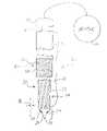
- FIG. 1is a fragmented elevational view of the bur of the present invention.
- FIG. 2is an enlarged partial front elevational view of the tip portion of the bur depicted in FIG. 1 .
- FIG. 3is an enlarged broken front elevational view of the tip portion of the dental bur depicted in FIG. 1 showing another embodiment thereof.
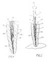
- FIG. 4is a sectional view of a tooth with a broken composite post therewithin.
- FIG. 5is a sectional view showing the bur of the present invention in use, removing the broken post depicted in FIG. 4 .
- Dental bur 10includes as one of its elements a rotatable shaft 12 which is connected to a conventional hand piece (not shown) and rotated by a motor 14 .
- motor 14rotates shaft 12 at about 40,000 RPMs.
- Shaft 12includes recesses 16 which are of a conventional configuration to lock into existing sources of rotation found in a dental practitioner's facility.
- Rotatable shaft 12may be formed of any suitable material such as carbon steel.
- Rotatable shaft 12includes a proximal portion 18 and a distal portion 20 relative to engagement end 22 which eventually links to motor 14 .
- Bur 10includes as one of its elements a tip 22 located at the distal end 20 of rotatable shaft 12 .
- Tip 22is rounded and includes a smooth surface 24 which lacks a cutting structure.
- End 26may take the form of a sharp terminus, FIG. 2 , or may be formed into an end 28 which is rounded to a certain degree, FIG. 3 .
- surface 29may be slightly concave.
- end 22is intended to generate heat through friction upon the rotation of shaft 12 when in contact with composite material, which will discussed in detail hereinafter.
- Means 30is also found in the present invention for removing composite material from a broken composite dental post.
- Means 30may take the form of a fluted surface 32 having a plurality of flutes or ridges 34 which extend outwardly to a certain degree. Flutes 34 are formed on rotatable shaft 12 with a very low rake angle 36 , typically ranging between 5 and 25 degrees.
- Proximal portion 18also includes dentin-abrading means 36 which is shown in the form of an abrading surface 38 .
- Abrading surface 38may be composed of a plurality of diamond particles 40 adhered to rotatable shaft 12 . In this format, abrading surface 38 generates a minimum of heat and dissipates such generated heat easily, as will be described as the specification continues. Thus, abrading surface 38 is essentially in the form of a rasp.
- FIGS. 4 and 5depict the circumstances and use of the present invention 10 .
- FIG. 4depicts a tooth 42 having a dentin structure 44 .
- a canal 46contains a broken composite post 48 and canal filling material 50 , which may be gutta percha.
- Edge portion 52 of post 48indicates the broken interface between post 48 and a crown portion which has been removed.
- Composite posts 48may be formed of side-by-side carbon fiber strands 54 which are placed in a matrix 56 of a binder such as an epoxy material.
- the dental practitioneroperates bur 10 by first drilling a pilot hole at the top portion of composite post 48 near edge 52 in order to center bur 10 . Bur 10 is then rotated by motor 14 according to directional arrow 58 .
- Such rotationmay take place at a rate of about 40,000 RPM.
- Tip 22contacts composite post 48 and generates a great deal of heat to melt the composite material in its vicinity. Such melting is due to the smooth surface 24 of tip 22 . Bur 10 is then guided through broken post 48 via such melting process as being the path of least resistance downwardly through canal 46 . If per chance, tip 28 were to touch dentin material 44 , tip 22 would not damage the same since there is no cutting structure. As bur 10 travels down canal 48 , means 30 removes composite material 60 . Bur 10 continues its travel until it reaches gutta purcha section 50 of canal 48 .
- dentin abrading means 36contacts the upper wall 62 of canal 48 and removes a small degree of dentin to provide an unencumbered surface.
- a new dental postis inserted within canal 46 and cemented to wall 62 .
- a new crown portion(not shown) is then attached to the new post to complete to restoration process.
Landscapes
- Health & Medical Sciences (AREA)
- Oral & Maxillofacial Surgery (AREA)
- Dentistry (AREA)
- Epidemiology (AREA)
- Life Sciences & Earth Sciences (AREA)
- Animal Behavior & Ethology (AREA)
- General Health & Medical Sciences (AREA)
- Public Health (AREA)
- Veterinary Medicine (AREA)
- Dental Tools And Instruments Or Auxiliary Dental Instruments (AREA)
Abstract
Description
Claims (9)
Priority Applications (2)
| Application Number | Priority Date | Filing Date | Title |
|---|---|---|---|
| US10/274,568US6902400B1 (en) | 2002-10-18 | 2002-10-18 | Dental bur |
| US10/729,572US7347692B2 (en) | 2002-10-18 | 2003-12-03 | Dental bur |
Applications Claiming Priority (1)
| Application Number | Priority Date | Filing Date | Title |
|---|---|---|---|
| US10/274,568US6902400B1 (en) | 2002-10-18 | 2002-10-18 | Dental bur |
Related Child Applications (1)
| Application Number | Title | Priority Date | Filing Date |
|---|---|---|---|
| US10/729,572Continuation-In-PartUS7347692B2 (en) | 2002-10-18 | 2003-12-03 | Dental bur |
Publications (1)
| Publication Number | Publication Date |
|---|---|
| US6902400B1true US6902400B1 (en) | 2005-06-07 |
Family
ID=32106472
Family Applications (1)
| Application Number | Title | Priority Date | Filing Date |
|---|---|---|---|
| US10/274,568Expired - Fee RelatedUS6902400B1 (en) | 2002-10-18 | 2002-10-18 | Dental bur |
Country Status (1)
| Country | Link |
|---|---|
| US (1) | US6902400B1 (en) |
Cited By (5)
| Publication number | Priority date | Publication date | Assignee | Title |
|---|---|---|---|---|
| US20060008772A1 (en)* | 2002-12-30 | 2006-01-12 | Izidor Brajnovic | Drill |
| US20070298376A1 (en)* | 2006-06-27 | 2007-12-27 | Straumann Holding Ag | Bur for dental implantology |
| US20080161812A1 (en)* | 2006-09-29 | 2008-07-03 | Depuy Products, Inc. | Calcar planar |
| USD679837S1 (en)* | 2011-12-19 | 2013-04-09 | Amir Hashem Shahidi Bonjar | Expandable dental micromotor bur |
| USD875247S1 (en)* | 2018-08-30 | 2020-02-11 | Sharareh Tajbakhsh | Polishing tip |
Citations (3)
| Publication number | Priority date | Publication date | Assignee | Title |
|---|---|---|---|---|
| US2453696A (en)* | 1947-01-13 | 1948-11-16 | Brooks Phillips | Dental root preparation instrument |
| US2807264A (en)* | 1953-09-10 | 1957-09-24 | Albert C Tuck | Instruments for contouring bones |
| US5275563A (en)* | 1992-09-02 | 1994-01-04 | Essential Dental Systems, Inc. | Dental post extracting drill |
- 2002
- 2002-10-18USUS10/274,568patent/US6902400B1/ennot_activeExpired - Fee Related
Patent Citations (3)
| Publication number | Priority date | Publication date | Assignee | Title |
|---|---|---|---|---|
| US2453696A (en)* | 1947-01-13 | 1948-11-16 | Brooks Phillips | Dental root preparation instrument |
| US2807264A (en)* | 1953-09-10 | 1957-09-24 | Albert C Tuck | Instruments for contouring bones |
| US5275563A (en)* | 1992-09-02 | 1994-01-04 | Essential Dental Systems, Inc. | Dental post extracting drill |
Cited By (9)
| Publication number | Priority date | Publication date | Assignee | Title |
|---|---|---|---|---|
| US20060008772A1 (en)* | 2002-12-30 | 2006-01-12 | Izidor Brajnovic | Drill |
| US7665989B2 (en)* | 2002-12-30 | 2010-02-23 | Nobel Biocare Services Ag | Drill |
| US8038445B2 (en) | 2002-12-30 | 2011-10-18 | Nobel Biocare Services, Ag | Methods of forming at least one hole in a jaw bone |
| US20070298376A1 (en)* | 2006-06-27 | 2007-12-27 | Straumann Holding Ag | Bur for dental implantology |
| US10456144B2 (en)* | 2006-06-27 | 2019-10-29 | Straumann Holding Ag | Bur for dental implantology |
| US20080161812A1 (en)* | 2006-09-29 | 2008-07-03 | Depuy Products, Inc. | Calcar planar |
| US8052687B2 (en)* | 2006-09-29 | 2011-11-08 | Depuy Products, Inc. | Calcar planar |
| USD679837S1 (en)* | 2011-12-19 | 2013-04-09 | Amir Hashem Shahidi Bonjar | Expandable dental micromotor bur |
| USD875247S1 (en)* | 2018-08-30 | 2020-02-11 | Sharareh Tajbakhsh | Polishing tip |
Similar Documents
| Publication | Publication Date | Title |
|---|---|---|
| CA2500644C (en) | Improved dental bur | |
| US6976844B2 (en) | Ultrasonic microtube dental instruments and methods of using same | |
| EP0257961B1 (en) | Dental root canal shaping file | |
| Ruddle | Nonsurgical retreatment | |
| US4365958A (en) | Combined dental drill and anchor pin | |
| US4990088A (en) | Dental tool combining reamer and router | |
| Gianluca | The K3 rotary nickel titanium instrument system | |
| US20070238068A1 (en) | Self-limiting depth gauge spherical dental burr and method of use | |
| EP0444155A4 (en) | Dental reamer tool | |
| US6902400B1 (en) | Dental bur | |
| US4259069A (en) | Hand tool for finishing dental fillings | |
| JPS61247446A (en) | Dental drill | |
| Nehme | A new approach for the retrieval of broken instruments | |
| US20030232307A1 (en) | Grinding bar | |
| US5316478A (en) | Dental post with cutting surfaces | |
| Janardanan et al. | Coronal disassembly systems and techniques: An overview | |
| US20050186534A1 (en) | Endodontic instrument set and method of using the same | |
| US20140241819A1 (en) | Safety Head Bur | |
| KR102638863B1 (en) | Drill device for dental implant | |
| EP4241722B1 (en) | Dental burs for anatomy and reducing anesthetic use | |
| US7198486B2 (en) | Rotary dental file having a safe breakage point | |
| Rollings et al. | Posts–when it all goes wrong! Part 2: post removal techniques | |
| KR101968421B1 (en) | Dental bur | |
| US20150024346A1 (en) | Method of removing oral root tip | |
| US20250082437A1 (en) | Surgical Protector for Dental Devices |
Legal Events
| Date | Code | Title | Description |
|---|---|---|---|
| AS | Assignment | Owner name:MTI PRECISION PRODUCTS, INC., NEW JERSEY Free format text:ASSIGNMENT OF ASSIGNORS INTEREST;ASSIGNOR:ROETZER, PATRICK L.;REEL/FRAME:013611/0510 Effective date:20021217 | |
| FEPP | Fee payment procedure | Free format text:PAYOR NUMBER ASSIGNED (ORIGINAL EVENT CODE: ASPN); ENTITY STATUS OF PATENT OWNER: LARGE ENTITY | |
| AS | Assignment | Owner name:ROETZER, PATRICK L., CALIFORNIA Free format text:ASSIGNMENT OF ASSIGNORS INTEREST;ASSIGNOR:MTI PRECISION PRODUCTS, INC.;REEL/FRAME:017384/0693 Effective date:20030918 | |
| AS | Assignment | Owner name:MTI PRECISION PRODUCTS, LLC, NEW JERSEY Free format text:ASSIGNMENT OF ASSIGNORS INTEREST;ASSIGNORS:ROETZER, PATRICK L.;FELDMAN, MICHAEL;REEL/FRAME:017908/0242;SIGNING DATES FROM 20040421 TO 20040422 | |
| FPAY | Fee payment | Year of fee payment:4 | |
| REMI | Maintenance fee reminder mailed | ||
| REMI | Maintenance fee reminder mailed | ||
| LAPS | Lapse for failure to pay maintenance fees | ||
| STCH | Information on status: patent discontinuation | Free format text:PATENT EXPIRED DUE TO NONPAYMENT OF MAINTENANCE FEES UNDER 37 CFR 1.362 | |
| FP | Lapsed due to failure to pay maintenance fee | Effective date:20130607 | |
| FEPP | Fee payment procedure | Free format text:PAT HOLDER NO LONGER CLAIMS SMALL ENTITY STATUS, ENTITY STATUS SET TO UNDISCOUNTED (ORIGINAL EVENT CODE: STOL); ENTITY STATUS OF PATENT OWNER: LARGE ENTITY |