US6902277B1 - Housing for a spatial light modulator - Google Patents
Housing for a spatial light modulatorDownload PDFInfo
- Publication number
- US6902277B1 US6902277B1US10/752,338US75233804AUS6902277B1US 6902277 B1US6902277 B1US 6902277B1US 75233804 AUS75233804 AUS 75233804AUS 6902277 B1US6902277 B1US 6902277B1
- Authority
- US
- United States
- Prior art keywords
- spatial light
- light modulator
- frame
- housing
- support element
- Prior art date
- Legal status (The legal status is an assumption and is not a legal conclusion. Google has not performed a legal analysis and makes no representation as to the accuracy of the status listed.)
- Expired - Fee Related
Links
Images


Classifications
- G—PHYSICS
- G02—OPTICS
- G02B—OPTICAL ELEMENTS, SYSTEMS OR APPARATUS
- G02B7/00—Mountings, adjusting means, or light-tight connections, for optical elements
- G02B7/003—Alignment of optical elements
- G—PHYSICS
- G02—OPTICS
- G02B—OPTICAL ELEMENTS, SYSTEMS OR APPARATUS
- G02B7/00—Mountings, adjusting means, or light-tight connections, for optical elements
- G02B7/006—Filter holders
- H—ELECTRICITY
- H04—ELECTRIC COMMUNICATION TECHNIQUE
- H04N—PICTORIAL COMMUNICATION, e.g. TELEVISION
- H04N5/00—Details of television systems
- H04N5/74—Projection arrangements for image reproduction, e.g. using eidophor
- H04N5/7416—Projection arrangements for image reproduction, e.g. using eidophor involving the use of a spatial light modulator, e.g. a light valve, controlled by a video signal
- H04N5/7441—Projection arrangements for image reproduction, e.g. using eidophor involving the use of a spatial light modulator, e.g. a light valve, controlled by a video signal the modulator being an array of liquid crystal cells
- H—ELECTRICITY
- H04—ELECTRIC COMMUNICATION TECHNIQUE
- H04N—PICTORIAL COMMUNICATION, e.g. TELEVISION
- H04N9/00—Details of colour television systems
- H04N9/12—Picture reproducers
- H04N9/31—Projection devices for colour picture display, e.g. using electronic spatial light modulators [ESLM]
- H04N9/3102—Projection devices for colour picture display, e.g. using electronic spatial light modulators [ESLM] using two-dimensional electronic spatial light modulators
- H04N9/3105—Projection devices for colour picture display, e.g. using electronic spatial light modulators [ESLM] using two-dimensional electronic spatial light modulators for displaying all colours simultaneously, e.g. by using two or more electronic spatial light modulators
- H—ELECTRICITY
- H04—ELECTRIC COMMUNICATION TECHNIQUE
- H04N—PICTORIAL COMMUNICATION, e.g. TELEVISION
- H04N9/00—Details of colour television systems
- H04N9/12—Picture reproducers
- H04N9/31—Projection devices for colour picture display, e.g. using electronic spatial light modulators [ESLM]
- H04N9/3141—Constructional details thereof
- H04N9/317—Convergence or focusing systems
Definitions
- This inventiongenerally relates to a digital projection apparatus that uses a liquid crystal device as an area spatial light modulator and more particularly relates to an apparatus and method for achieving improved contrast using an adjustable compensator in the optical path.
- digital projection systemsIn order to be considered as suitable replacements for conventional film projectors, digital projection systems must meet demanding requirements for image quality. This is particularly true for cinematic projection systems. In order to provide a competitive alternative to conventional cinematic-quality projectors, digital projection apparatus must meet high standards of performance, providing high resolution, wide color gamut, high brightness, and frame-sequential contrast ratios exceeding 1,000:1.
- the most promising solutions for digital cinema projectionemploy, as image forming devices, one of two types of spatial light modulators.
- the first type of spatial light modulatoris the digital micromirror device (DMD), developed by Texas Instruments, Inc., Dallas, Tex.
- DMD devicesare described in a number of patents, for example U.S. Pat. Nos. 4,441,791; 5,535,047; 5,600,383 (all to Hornbeck); and U.S. Pat. No. 5,719,695 (Heimbuch).
- Optical designs for projection apparatus employing DMDsare disclosed in U.S. Patent No. 5,914,818 (Tejada et al.); U.S. Pat. No. 5,930,050 (Dewald); U.S. Pat. No.
- DMD-based projectorsdemonstrate some capability to provide the necessary light throughput, contrast ratio, and color gamut, however, inherent resolution limitations (with current devices providing only 1024 ⁇ 768 pixels) and high component and system costs have restricted DMD acceptability for high-quality digital cinema projection.
- the second type of spatial light modulator used for digital projectionis the liquid crystal device (LCD).
- the LCDforms an image as an array of pixels by selectively modulating the polarization state of incident light for each corresponding pixel.
- LCDsappear to have advantages as spatial light modulators for high-quality digital cinema projection systems.
- electronic projection apparatusthat utilize LCD spatial light modulators are those disclosed in U.S. Pat. No. 5,808,795 (Shimomura et al.); U.S. Pat. No. 5,798,819 (Hattori et al.); U.S. Pat. No. 5,918,961 (Ueda); U.S. Pat. No. 6,010,221 (Maki et al.); and U.S. Pat. No.
- JVC and othershave developed vertically aligned LCDs, which are addressed via a silicon backplane.
- the JVC LCD devicesare described, in part, in U.S. Pat. No. 5,570,213 (Ruiz et al.) and U.S. Pat. No. 5,620,755 (Smith, Jr. et al.).
- vertically aligned LCDspromise to provide much higher modulation contrast ratios (in excess of 2,000:1). It is instructive to note that, in order to obtain on-screen frame sequential contrast of 1,000:1 or better, the entire system must produce greater than 1,000:1 contrast, and both the LCDs and any necessary internal polarization optics must each separately provide ⁇ 2,000:1 contrast.
- Contrasttends to decrease as spectral bandwidth increases and as the f/# decreases.
- Modulation contrast of LCD componentsis also reduced by residual de-polarization or misoriented polarization, such as by thermally induced stress birefringence.
- the optical performance provided by LCD based electronic projection systemis, in large part, defined by the characteristics of the LCDs themselves and by the polarization optics that support LCD projection.
- the performance of polarization separation optics, such as polarization beamsplitters, pre-polarizers, and polarizer/analyzer components,is of particular importance for obtaining high contrast ratios.
- Wire grid polarizershave been in existence for a number of years, and were initially used in radio-frequency applications and in optical applications using non-visible light sources. Until recently, use of wire grid polarizers with light in the visible spectrum has been limited, largely due to constraints of device performance or manufacture. However, as is disclosed in U.S. Pat. No. 6,122,103 (Perkins et al.), higher quality wire grid polarizers and beamsplitters have now been developed for broadband use in the visible spectrum. Among these are new devices commercially available from Moxtek Inc. of Orem, Utah. While existing wire grid polarizers, including the devices described in U.S. Pat. No.
- wire grid polarization devicesWhen compared against standard polarizers, wire grid polarization devices exhibit relatively high extinction ratios and high efficiency. Additionally, the contrast performance of these wire grid devices also has broader angular acceptance (NA or numerical aperture) and more robust thermal performance (with less opportunity for thermally induced stress birefringence) than standard polarization devices. Furthermore, the wire grid polarizers are robust relative to harsh environmental conditions, such as light intensity, temperature, and vibration. These devices perform well under conditions of different color channels, with the exception that response within the blue light channel may require additional compensation.
- Wire grid polarizing beamsplitter (PBS) deviceshave been employed in some digital projection apparatus, with some degree of success.
- U.S. Pat. No. 6,243,199discloses use of a broadband wire grid polarizing beamsplitter for projection display applications.
- U.S. Pat. Nos. 6,234,634 and 6,447,120disclose a wire grid polarizing beamsplitter that functions as both polarizer and analyzer in a digital image projection system.
- U.S. Pat. No. 6,234,634states that very low effective f/#s can be achieved using wire grid PBS, with some loss of contrast, however. Notably, neither U.S. Pat. No.
- 5,039,185discloses a homeotropic LCD with compensator provided between a polarizer/analyzer pair.
- a 1 ⁇ 4 waveplate used as a compensatorhas been disclosed, as in U.S. Pat. No. 5,576,854 (Schmidt et al.), which also discloses use of additional phase retardation as compensation for inherent LCD birefringent effects.
- the polarization beamsplitterprovides acceptable contrast when incident light is within a low numerical aperture.
- the conflicting goals of maintaining high brightness and high contrast ratiopresent a significant design problem for polarization components. Light leakage in the OFF state must be minimal in order to achieve high contrast levels. Yet, light leakage is most pronounced for incident light at the oblique angles required for achieving high brightness.
- Compensator requirements for wire grid polarizing beamsplitter devicesdiffer significantly from more conventional use of compensators with polarizing beamsplitter devices based on the MacNeille prism design as was noted in reference to U.S. Pat. No. 5,576,854.
- performance resultsindicate that the use of a 1 ⁇ 4 waveplate, a conventional approach when using the MacNeille prism, is not a suitable solution and can even degrade contrast ratio when used in combination with a wire grid polarizing beamsplitter.
- a number of problemsmust be solved when using compensator components in a digital cinema projection system that employs LCD spatial light modulators with wire grid polarization components.
- the need for compact packaging of optical components in a digital projection apparatusintroduces space constraints that can limit the number of options available for positioning a compensator. This physical constraint is made even more demanding for optical systems that use a low f/#. As has been noted hereinabove, low f/# systems are advantaged for achieving higher overall luminance. It is also desirable to allow some degree of adjustability for compensator components in a digital projector design. Allowing adjustability, however, tends to make packaging requirements even more complex. As another consideration, there is also a need to protect the LCD and other components from ambient dust and dirt, which would degrade image quality and overall device performance.
- each of the above solutionsfails to meet one or more important requirements for compactness and suitability for a low f/# system, precision adjustability of compensator retardance, and protection of the LCD from dust and dirt contamination.
- none of these solutionsis ideally suited for mounting a compact adjustable compensator for a low f/# optical system in an electronic projection apparatus that comprises an LCD with a wire grid polarization beamsplitter.
- the solution of U.S. Pat. No. 5,576,854while it provides adjustability, is not suitable for a system using low f/# optics and does not provide dust protection.
- 6,460,998is intended only to provide a very limited adjustability of a polarizer component (not a compensator) over a few degrees, where this component is pivoted in an off-axis manner. This solution could be used in a low f/# system; however, there is no consideration for dust protection noted in U.S. Pat. No. 6,460,998.
- U.S. Pat. No. 6,280,036provides only a lens and seal against the surface of an LCD, with no accommodation for an adjustable compensator.
- U.S. Pat. Nos. 5,743,611 and 6,375,328provide dust protection for the LCD, but with no adjustability for polarization or compensator components.
- U.S. Pat. No. 6,414,734provides a possible method for sealing any number of support components with an LCD, which could be useful in a low f/# system and is relatively dust-free, but does not provide any adjustability of components.
- the liquid crystal light modulator itselfis provided within a frame and protected by a glass cover plate.
- a cover plateis detrimental to the optical path, often compromising optical performance.
- a glass plate in the optical pathintroduces the potential for various undesirable optical effects, aberrations, and unwanted reflection or refraction of incident or stray light.
- some type of protection from dust and dirtmust be provided to the LCD, even with the potential disadvantages of a glass cover plate.
- the present inventionprovides a housing for a spatial light modulator, wherein the spatial light modulator provides a modulated image beam.
- the housingcomprises:
- FIG. 1is a block diagram of a digital cinema projector using three spatial light modulators
- FIG. 2is an exploded perspective view showing a first housing supporting a spatial light modulator and a second housing that fits against the first housing, supporting an adjustable compensator;
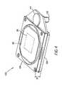
- FIG. 3is an exploded perspective view showing components of the second housing that supports the adjustable compensator
- FIG. 4is a perspective view showing an assembled mounting according to the present invention.
- FIG. 5is a side view showing output light cones emitted from the spatial light modulator mounting according to the present invention.
- FIG. 1there is shown a simplified schematic for a digital motion picture projection apparatus 10 using LCD components.
- Individual components within each pathare labeled with an appended r, g, or b, appropriately.
- distinctions between color channelsare specified when necessary.
- a light source 20provides unmodulated light, which is conditioned by uniformizing optics 22 to provide a uniform illumination, directed through an illumination relay lens 80 to a dichroic separator 27 .
- Dichroic separator 27splits the white light into red, green, and blue color channels.
- lightgoes to a light modulation assembly 38 r , 38 g , 38 b in which a relay lens 82 r , 82 g , 82 b directs light through a prepolarizer 70 to a polarizing beamsplitter 24 r , 24 g , 24 b .
- a relay lens 82 r , 82 g , 82 bdirects light through a prepolarizer 70 to a polarizing beamsplitter 24 r , 24 g , 24 b .
- Light having the desired polarization stateis transmitted through polarizing beamsplitter 24 r , 24 g , 24 b and is then modulated by a spatial light modulator 30 r , 30 g , 30 b , which selectively modulates the polarization state of the incident light over an array of pixel sites.
- spatial light modulator 30 r , 30 g , 30 bforms an image.
- a dichroic combiner 26typically an X-cube, Philips prism, or combination of dichroic surfaces in conventional systems.
- An optional color-selective polarization filter 60 r , 60 g , 60 bmay also be provided in the modulated light path of light modulation assembly 38 r , 38 g , 38 b .
- Dichroic combiner 26combines the red, green, and blue modulated images from separate optical axes O r , O g , O b to form a combined, multicolor image for a projection lens 32 along a common optical axis 0 for projection onto a display surface 40 , such as a projection screen.
- the reflective liquid crystal device (LCD) of FIG. 1is a type of spatial light modulator that is widely used in digital projector design. This device accepts polarized light and modulates the polarization of the incident light to provide colored light beam as output.
- a polarizing beamsplitter prismsuch as a McNeille prism, or a wire grid polarizing beamsplitter is typically employed along with the support of one or more polarizing elements, configured as polarizers and analyzers.
- a transmissive type of LCDcould be employed in one or more light modulation assemblies 38 r , 38 g , or 38 b , with a suitable reconfiguration of supporting polarization components, as is well known in the imaging arts.
- a compensator 90 r , 90 g , 90 bis used, positioned in the optical path between the LCD spatial light modulator 30 r , 30 g , 30 b and its corresponding polarizing beamsplitter 24 r , 24 g , 24 b .
- FIG. 1shows the position of each of optional compensators 90 r , 90 g , 90 b as a dotted line in each respective optical path.
- spacing constraintis a key consideration when adding a compensator for one or more color light modulation assemblies 38 r , 38 g , or 38 b .
- each color light modulation assembly 38 r , 38 g , 38 bhave the same optical path length. Any increase to this distance in one color light path would require similar increases in the other light paths. Additionally, although not visible in the schematic view of FIG. 1 , there are tight constraints on relative component placement within each color light modulation assembly 38 r , 38 g , 38 b , particularly since each color path uses low f/# optics for maximum brightness. The requirement for adjustability of the compensator further complicates the space problem.
- Housing 100has two major subassemblies, a first frame 102 and a second frame 104 .
- First frame 102holds spatial light modulator 30 with a counter electrode glass 108 in a nest 106 .
- Second frame 104holds compensator 90 within a ring 114 over an aperture 124 (shown in phantom in FIG. 2 ).
- Compensator 90is shown as 8-sided, but could be round, square, or any other suitable shape.
- Compensator 90may comprise a series of oriented birefringent polymer sheet materials mounted to a glass substrate.
- Compensator 90may also comprise a birefringent dielectric optical coating, or an anisotropic form birefringent optical structure, fabricated on a glass substrate.
- compensator 90does not come in contact with edges of ring 114 or second frame 104 , thereby allowing for thermal expansion of compensator 90 without constraint.
- a pinion gear 110 on second frame 104cooperates with gear teeth on ring 114 to allow adjustable rotation of compensator 90 about optical axis O c and always parallel to the spatial light modulator 30 .
- Pinion gear 110allows adjustment using a slot 112 or other coupling mechanism. Alternately, pinion gear 110 could be part of an external removable alignment fixture.
- first frame 102should be thermally compatible with characteristics of the substrate of spatial light modulator 30 , which is typically a silicon substrate. Ideally, the material used for first frame 102 should be rigid and should have a coefficient of thermal expansion (CTE) that is closely identical to the CTE of the substrate of spatial light modulator 30 .
- CTEcoefficient of thermal expansion
- Compensator 90is seated within ring 114 that provides gear teeth (not shown) that engage pinion gear 110 for rotation.
- a retainer plate 116stainless steel in a preferred embodiment, secured by adhesive or mechanical fasteners (not shown) holds ring 114 movably in place in a recess 122 against an aperture plate 118 .
- housing 100as assembled, with second frame 104 mounted on first frame 102 . It can be seen that housing 100 provides a relatively thin package containing both spatial light modulator 30 and its corresponding compensator 90 , adjustable by accessing slot 112 .
- Pinion gear 110 and ring 114allow rotation of compensator 90 over a wide range of angles, while centered about optical axis O c as was shown in FIG. 2 . It is intended that compensator 90 experience rotation in a plane nominally parallel to the plane of the modulator 30 . In a preferred embodiment, on-axis rotation of 270 degrees or greater is available using the pinion gear 110 /ring 114 arrangement.
- compensator 90is rotated a suitable amount (perhaps only a few degrees) to a nominal fixed position where the image contrast is optimized, for example to maximum contrast or for maximum average contrast as seen across the projected image.
- the arrangement of pinion gear 110 and ring 114enables adjustment of compensator 90 rotation, but does not add to the depth dimension D 1 of housing 100 .
- Optional gasketing components(not shown) used in coupling second frame 104 to first frame 102 allow the surface of spatial light modulator 30 to be sealed more effectively from damage, dust, and dirt.
- housing 100adds an adjustable compensator 90 to the basic package for LCD spatial light modulator 30 and eliminates the need for a glass cover plate.
- housing 100 shown in FIGS. 2 , 3 , and 4although it adds adjustable compensator 90 , actually reduces the depth D 1 of the support package for spatial light modulator 30 by more than 0.080 inches over a conventional frame that is commercially used, maintaining the same level of dust protection.
- FIG. 5there is shown, from a side view, representative light cones 120 directed toward housing 100 from beamsplitter 24 in a preferred embodiment in which a reflective type of LCD spatial light modulator 30 is used.
- the small distance D 2 allowed between the extreme edge of light cones 120 and housing 100is minimal in designs using a low f/#.
- the use of housing 100allows the low f/# design of projection apparatus 10 to be maintained, even where there are considerable space restraints while still allowing for sufficient six axis adjustment of housing 100 .
- the apparatus of the present inventionalso maintains protection of the LCD surface from dust and dirt, without a cover plate.
- the present inventionallows a straightforward adjustment procedure for obtaining a suitable alignment of compensator 90 in the optical path, using adjustment procedures well known in the optical calibration arts.
- compensator 90 r , 90 g , 90 b within each color light modulation assembly 38 r , 38 g , 38 bcan be individually tuned to obtain suitable retardance in the color path.
- housing 100 of the present inventioncould also be used in an imaging apparatus that uses a transmissive LCD.
- a second aperture 124 ′shown in phantom in FIG. 2
- the design of housing 100can also be modified to provide a small tilt or wedge angle between the compensator 90 and the modulator 30 . While these two elements are nominally located in parallel planes, a tilt angle between them can reduce any optical interference effects between the components which would effect frame sequential and ANSI contrast. As tilt of the compensator 90 relative to the modulator 30 can make the polarization compensation non-uniform with angle, use of tilt has to be undertaken with care.
- an apparatus and method for mounting an adjustable compensator or other component in the optical path of an LCD spatial light modulatorproviding an arrangement of components that is especially well suited to a system using low f/# optics, that protects the LCD surface from dust and dirt, and that allows easy adjustment while employing a small number of parts.
Landscapes
- Engineering & Computer Science (AREA)
- Multimedia (AREA)
- Signal Processing (AREA)
- Physics & Mathematics (AREA)
- General Physics & Mathematics (AREA)
- Optics & Photonics (AREA)
- Chemical & Material Sciences (AREA)
- Crystallography & Structural Chemistry (AREA)
- Liquid Crystal (AREA)
Abstract
Description
- U.S. Pat. No. 5,576,854 (Schmidt et al.) discloses an adjustable compensator plate disposed between a polarization plate and a liquid crystal light valve to compensate for polarization irregularities in the cone of light projected onto the LCD modulator;
- U.S. Pat. No. 6,460,998 (Watanabe) discloses a polarizer having an angle adjustment mechanism in which a first frame arranged in the vicinity of an electrooptic device pivotally supports a second frame having a polarizer thereon, allowing a slight adjustment of the polarizer about a pivot point, where the pivot point is optically off-axis;
- U.S. Pat. No. 6,280,036 (Suzuki) discloses a dust preventive structure for spatial light modulator components within a digital projection apparatus, with a field lens attached to each LCD device;
- U.S. Pat. No. 5,743,611 (Yamaguchi et al.) discloses dust protection by hermetically sealed components about an LCD;
- U.S. Pat. No. 6,375,328 (Hashizume et al.) discloses transparent cover plates bonded to the surface of LCD spatial light modulators; and
- U.S. Pat. No. 6,414,734 (Shigeta et al.) discloses a sealed unit that houses an LCD with support components.
- (a) a first frame for supporting the spatial light modulator in the path of an incident illumination beam;
- (b) a second frame, fitted against the first frame, the second frame comprising:
- (i) an aperture for the modulated image beam from the spatial light modulator; and
- (ii) a support element for disposing an optical component proximate the aperture, the support element rotatably adjustable about an axis.
- 10 projection apparatus
- 20 light source
- 22 uniformizing optics
- 24 polarizing beamsplitter
- 24rpolarizing beamsplitter, red
- 24gpolarizing beamsplitter, green
- 24bpolarizing beamsplitter, blue
- 26 dichroic combiner
- 27 dichroic separator
- 28rmagnifying relay lens, red
- 28gmagnifying relay lens, green
- 28bmagnifying relay lens, blue
- 30 spatial light modulator
- 30rspatial light modulator, red
- 30gspatial light modulator, green
- 30bspatial light modulator, blue
- 31 folding mirror
- 32 projection lens
- 38rlight modulation assembly, red
- 38glight modulation assembly, green
- 38blight modulation assembly, blue
- 40 display surface
- 60rcolor-selective polarization filter, red
- 60gcolor-selective polarization filter, green
- 60bcolor-selective polarization filter, blue
- 70 prepolarizer
- 72 analyzer
- 80 illumination relay lens
- 82rrelay lens, red
- 82grelay lens, green
- 82brelay lens, blue
- 90 compensator
- 90rcompensator, red
- 90gcompensator, green.
- 90bcompensator, blue
- 100 housing
- 102 first frame
- 104 second frame
- 106 nest
- 108 counter electrode glass
- 110 pinion gear
- 112 slot
- 114 ring
- 116 retainer plate
- 118 aperture plate
- 120 light cone
- 122 recess
- 124 aperture
- 124′ aperture
Claims (29)
Priority Applications (5)
| Application Number | Priority Date | Filing Date | Title |
|---|---|---|---|
| US10/752,338US6902277B1 (en) | 2004-01-06 | 2004-01-06 | Housing for a spatial light modulator |
| PCT/US2004/043800WO2005069610A1 (en) | 2004-01-06 | 2004-12-28 | A housing for a spatial light modulator |
| EP04815801AEP1704715A1 (en) | 2004-01-06 | 2004-12-28 | A housing for a spatial light modulator |
| CNA2004800400244ACN1902917A (en) | 2004-01-06 | 2004-12-28 | Housing for a spatial light modulator |
| TW094100210ATW200534772A (en) | 2004-01-06 | 2005-01-05 | A housing for a spatial light modulator |
Applications Claiming Priority (1)
| Application Number | Priority Date | Filing Date | Title |
|---|---|---|---|
| US10/752,338US6902277B1 (en) | 2004-01-06 | 2004-01-06 | Housing for a spatial light modulator |
Publications (1)
| Publication Number | Publication Date |
|---|---|
| US6902277B1true US6902277B1 (en) | 2005-06-07 |
Family
ID=34620650
Family Applications (1)
| Application Number | Title | Priority Date | Filing Date |
|---|---|---|---|
| US10/752,338Expired - Fee RelatedUS6902277B1 (en) | 2004-01-06 | 2004-01-06 | Housing for a spatial light modulator |
Country Status (5)
| Country | Link |
|---|---|
| US (1) | US6902277B1 (en) |
| EP (1) | EP1704715A1 (en) |
| CN (1) | CN1902917A (en) |
| TW (1) | TW200534772A (en) |
| WO (1) | WO2005069610A1 (en) |
Cited By (5)
| Publication number | Priority date | Publication date | Assignee | Title |
|---|---|---|---|---|
| US20060050215A1 (en)* | 2004-09-08 | 2006-03-09 | Akihide Haruyama | Liquid crystal device and projection display device |
| US20070064198A1 (en)* | 2005-09-09 | 2007-03-22 | Sanyo Electric Co., Ltd. | Projector device |
| US20070195257A1 (en)* | 2006-02-21 | 2007-08-23 | Jds Uniphase Corporation | LC imager panel assembly |
| US20120161392A1 (en)* | 2009-09-03 | 2012-06-28 | Nagy Richard | Game accessory, especially dice |
| US20130034823A1 (en)* | 2011-08-02 | 2013-02-07 | Rongguang Liang | Adaptive illumination method and apparatus for dental shade matching |
Families Citing this family (1)
| Publication number | Priority date | Publication date | Assignee | Title |
|---|---|---|---|---|
| CN104820284A (en)* | 2015-04-22 | 2015-08-05 | 蓝思科技(长沙)有限公司 | Glass with adjustable light intensity |
Citations (33)
| Publication number | Priority date | Publication date | Assignee | Title |
|---|---|---|---|---|
| US2403731A (en) | 1943-04-01 | 1946-07-09 | Eastman Kodak Co | Beam splitter |
| US4441791A (en) | 1980-09-02 | 1984-04-10 | Texas Instruments Incorporated | Deformable mirror light modulator |
| US4701028A (en) | 1984-05-18 | 1987-10-20 | Commissariat A L'energie Atomique | Liquid crystal cell which can have a homeotropic structure with compensated birefringence of said structure |
| US5039185A (en) | 1988-07-04 | 1991-08-13 | Stanley Electric Co., Ltd. | Homeotropic liquid crystal display device |
| US5298199A (en) | 1990-10-17 | 1994-03-29 | Stanley Electric Co., Ltd. | Optical birefringence compensator adapted for LCD |
| US5535047A (en) | 1995-04-18 | 1996-07-09 | Texas Instruments Incorporated | Active yoke hidden hinge digital micromirror device |
| US5570213A (en) | 1992-10-20 | 1996-10-29 | Hughes-Jvc Technology Corporation | Liquid crystal light valve with minimized double reflection |
| US5576854A (en) | 1993-11-12 | 1996-11-19 | Hughes-Jvc Technology Corporation | Liquid crystal light valve projector with improved contrast ratio and with 0.27 wavelength compensation for birefringence in the liquid crystal light valve |
| US5600383A (en) | 1990-06-29 | 1997-02-04 | Texas Instruments Incorporated | Multi-level deformable mirror device with torsion hinges placed in a layer different from the torsion beam layer |
| US5620755A (en) | 1991-06-14 | 1997-04-15 | Jvc - Victor Company Of Japan, Ltd. | Inducing tilted perpendicular alignment in liquid crystals |
| US5719695A (en) | 1995-03-31 | 1998-02-17 | Texas Instruments Incorporated | Spatial light modulator with superstructure light shield |
| US5743611A (en) | 1995-10-13 | 1998-04-28 | Sony Corporation | Projector |
| US5798819A (en) | 1995-12-12 | 1998-08-25 | Nikon Corporation | Projection-display apparatus and method providing improved brightness of projected color image |
| US5808795A (en) | 1995-03-06 | 1998-09-15 | Nikon Corporation | Projection type display apparatus |
| US5912762A (en) | 1996-08-12 | 1999-06-15 | Li; Li | Thin film polarizing device |
| US5914818A (en) | 1996-11-29 | 1999-06-22 | Texas Instruments Incorporated | Offset projection lens for use with reflective spatial light modulators |
| US5918961A (en) | 1996-05-10 | 1999-07-06 | Nikon Corporation | Projection type display device |
| US5930050A (en) | 1997-10-21 | 1999-07-27 | Texas Instruments Incorporated | Anamorphic lens for providing wide-screen images generated by a spatial light modulator |
| US5988818A (en)* | 1991-02-22 | 1999-11-23 | Seiko Epson Corporation | Projection type liquid crystal projector |
| US6008951A (en) | 1996-12-31 | 1999-12-28 | Texas Instruments Incorporated | Offset projection zoom lens with fixed rear group for reflective spatial light modulators |
| US6010221A (en) | 1997-05-22 | 2000-01-04 | Nikon Corporation | Projection type display apparatus |
| US6062694A (en) | 1995-03-06 | 2000-05-16 | Nikon Corporation | Projection type display apparatus |
| US6089717A (en) | 1996-09-02 | 2000-07-18 | Sony Corporation | Projector apparatus |
| US6122103A (en) | 1999-06-22 | 2000-09-19 | Moxtech | Broadband wire grid polarizer for the visible spectrum |
| US6234634B1 (en) | 1999-07-28 | 2001-05-22 | Moxtek | Image projection system with a polarizing beam splitter |
| US6243199B1 (en) | 1999-09-07 | 2001-06-05 | Moxtek | Broad band wire grid polarizing beam splitter for use in the visible wavelength region |
| US6280036B1 (en) | 1997-12-05 | 2001-08-28 | Canon Kabushiki Kaisha | Projection apparatus |
| US6375328B2 (en) | 1997-05-20 | 2002-04-23 | Seiko Epson Corporation | Optical modulation element and projector |
| US6414734B1 (en) | 1998-08-07 | 2002-07-02 | Victor Company Of Japan, Limited | Liquid crystal display device and liquid crystal projector |
| US6447120B2 (en) | 1999-07-28 | 2002-09-10 | Moxtex | Image projection system with a polarizing beam splitter |
| US6460998B1 (en) | 1999-03-08 | 2002-10-08 | Seiko Epson Corporation | Adjustment mechanism and projector employing the same |
| US6585378B2 (en) | 2001-03-20 | 2003-07-01 | Eastman Kodak Company | Digital cinema projector |
| US6733141B2 (en)* | 2001-09-04 | 2004-05-11 | Samsung Electronics Co., Ltd | Apparatus for fine-adjusting orientation of optical device |
Family Cites Families (5)
| Publication number | Priority date | Publication date | Assignee | Title |
|---|---|---|---|---|
| US4743763A (en)* | 1986-09-26 | 1988-05-10 | The United States Of America As Repesented By The United States Department Of Energy | Article mounting and position adjustment stage |
| US6072643A (en)* | 1993-12-21 | 2000-06-06 | Olympus Optical Co., Ltd. | Lens barrel |
| GB9704967D0 (en)* | 1997-03-11 | 1997-04-30 | Howard Foundation | Flicker photometer |
| US7027224B2 (en)* | 2001-01-31 | 2006-04-11 | Sharp Laboratories Of America, Inc. | Wave plate mounting |
| CN1575436A (en)* | 2001-08-30 | 2005-02-02 | 3M创新有限公司 | Apparatus and methods for mounting and aligning the optical elements of a projection image display system |
- 2004
- 2004-01-06USUS10/752,338patent/US6902277B1/ennot_activeExpired - Fee Related
- 2004-12-28WOPCT/US2004/043800patent/WO2005069610A1/ennot_activeApplication Discontinuation
- 2004-12-28EPEP04815801Apatent/EP1704715A1/ennot_activeWithdrawn
- 2004-12-28CNCNA2004800400244Apatent/CN1902917A/enactivePending
- 2005
- 2005-01-05TWTW094100210Apatent/TW200534772A/enunknown
Patent Citations (33)
| Publication number | Priority date | Publication date | Assignee | Title |
|---|---|---|---|---|
| US2403731A (en) | 1943-04-01 | 1946-07-09 | Eastman Kodak Co | Beam splitter |
| US4441791A (en) | 1980-09-02 | 1984-04-10 | Texas Instruments Incorporated | Deformable mirror light modulator |
| US4701028A (en) | 1984-05-18 | 1987-10-20 | Commissariat A L'energie Atomique | Liquid crystal cell which can have a homeotropic structure with compensated birefringence of said structure |
| US5039185A (en) | 1988-07-04 | 1991-08-13 | Stanley Electric Co., Ltd. | Homeotropic liquid crystal display device |
| US5600383A (en) | 1990-06-29 | 1997-02-04 | Texas Instruments Incorporated | Multi-level deformable mirror device with torsion hinges placed in a layer different from the torsion beam layer |
| US5298199A (en) | 1990-10-17 | 1994-03-29 | Stanley Electric Co., Ltd. | Optical birefringence compensator adapted for LCD |
| US5988818A (en)* | 1991-02-22 | 1999-11-23 | Seiko Epson Corporation | Projection type liquid crystal projector |
| US5620755A (en) | 1991-06-14 | 1997-04-15 | Jvc - Victor Company Of Japan, Ltd. | Inducing tilted perpendicular alignment in liquid crystals |
| US5570213A (en) | 1992-10-20 | 1996-10-29 | Hughes-Jvc Technology Corporation | Liquid crystal light valve with minimized double reflection |
| US5576854A (en) | 1993-11-12 | 1996-11-19 | Hughes-Jvc Technology Corporation | Liquid crystal light valve projector with improved contrast ratio and with 0.27 wavelength compensation for birefringence in the liquid crystal light valve |
| US5808795A (en) | 1995-03-06 | 1998-09-15 | Nikon Corporation | Projection type display apparatus |
| US6062694A (en) | 1995-03-06 | 2000-05-16 | Nikon Corporation | Projection type display apparatus |
| US5719695A (en) | 1995-03-31 | 1998-02-17 | Texas Instruments Incorporated | Spatial light modulator with superstructure light shield |
| US5535047A (en) | 1995-04-18 | 1996-07-09 | Texas Instruments Incorporated | Active yoke hidden hinge digital micromirror device |
| US5743611A (en) | 1995-10-13 | 1998-04-28 | Sony Corporation | Projector |
| US5798819A (en) | 1995-12-12 | 1998-08-25 | Nikon Corporation | Projection-display apparatus and method providing improved brightness of projected color image |
| US5918961A (en) | 1996-05-10 | 1999-07-06 | Nikon Corporation | Projection type display device |
| US5912762A (en) | 1996-08-12 | 1999-06-15 | Li; Li | Thin film polarizing device |
| US6089717A (en) | 1996-09-02 | 2000-07-18 | Sony Corporation | Projector apparatus |
| US5914818A (en) | 1996-11-29 | 1999-06-22 | Texas Instruments Incorporated | Offset projection lens for use with reflective spatial light modulators |
| US6008951A (en) | 1996-12-31 | 1999-12-28 | Texas Instruments Incorporated | Offset projection zoom lens with fixed rear group for reflective spatial light modulators |
| US6375328B2 (en) | 1997-05-20 | 2002-04-23 | Seiko Epson Corporation | Optical modulation element and projector |
| US6010221A (en) | 1997-05-22 | 2000-01-04 | Nikon Corporation | Projection type display apparatus |
| US5930050A (en) | 1997-10-21 | 1999-07-27 | Texas Instruments Incorporated | Anamorphic lens for providing wide-screen images generated by a spatial light modulator |
| US6280036B1 (en) | 1997-12-05 | 2001-08-28 | Canon Kabushiki Kaisha | Projection apparatus |
| US6414734B1 (en) | 1998-08-07 | 2002-07-02 | Victor Company Of Japan, Limited | Liquid crystal display device and liquid crystal projector |
| US6460998B1 (en) | 1999-03-08 | 2002-10-08 | Seiko Epson Corporation | Adjustment mechanism and projector employing the same |
| US6122103A (en) | 1999-06-22 | 2000-09-19 | Moxtech | Broadband wire grid polarizer for the visible spectrum |
| US6447120B2 (en) | 1999-07-28 | 2002-09-10 | Moxtex | Image projection system with a polarizing beam splitter |
| US6234634B1 (en) | 1999-07-28 | 2001-05-22 | Moxtek | Image projection system with a polarizing beam splitter |
| US6243199B1 (en) | 1999-09-07 | 2001-06-05 | Moxtek | Broad band wire grid polarizing beam splitter for use in the visible wavelength region |
| US6585378B2 (en) | 2001-03-20 | 2003-07-01 | Eastman Kodak Company | Digital cinema projector |
| US6733141B2 (en)* | 2001-09-04 | 2004-05-11 | Samsung Electronics Co., Ltd | Apparatus for fine-adjusting orientation of optical device |
Cited By (9)
| Publication number | Priority date | Publication date | Assignee | Title |
|---|---|---|---|---|
| US20060050215A1 (en)* | 2004-09-08 | 2006-03-09 | Akihide Haruyama | Liquid crystal device and projection display device |
| US20080278668A1 (en)* | 2004-09-08 | 2008-11-13 | Akihide Haruyama | Liquid crystal device and projection display device |
| US7570328B2 (en)* | 2004-09-08 | 2009-08-04 | Seiko Epson Corporation | Liquid crystal device and projection display device |
| US20070064198A1 (en)* | 2005-09-09 | 2007-03-22 | Sanyo Electric Co., Ltd. | Projector device |
| US7884887B2 (en)* | 2005-09-09 | 2011-02-08 | Sanyo Electric Co., Ltd. | Projector device comprising optical compensation sheet holder including turning member and sliding member |
| US20070195257A1 (en)* | 2006-02-21 | 2007-08-23 | Jds Uniphase Corporation | LC imager panel assembly |
| US20120161392A1 (en)* | 2009-09-03 | 2012-06-28 | Nagy Richard | Game accessory, especially dice |
| US8678388B2 (en)* | 2009-09-03 | 2014-03-25 | Co And Co Communication Reklam Es Hirdetesszervezo Kft | Game accessory, especially dice |
| US20130034823A1 (en)* | 2011-08-02 | 2013-02-07 | Rongguang Liang | Adaptive illumination method and apparatus for dental shade matching |
Also Published As
| Publication number | Publication date |
|---|---|
| CN1902917A (en) | 2007-01-24 |
| WO2005069610A1 (en) | 2005-07-28 |
| EP1704715A1 (en) | 2006-09-27 |
| TW200534772A (en) | 2005-10-16 |
Similar Documents
| Publication | Publication Date | Title |
|---|---|---|
| US6805445B2 (en) | Projection display using a wire grid polarization beamsplitter with compensator | |
| US6909473B2 (en) | Display apparatus and method | |
| US7131737B2 (en) | Housing for mounting a beamsplitter and a spatial light modulator with an output optical path | |
| JP4344285B2 (en) | Display device | |
| US5621486A (en) | Efficient optical system for a high resolution projection display employing reflection light valves | |
| US6769779B1 (en) | Housing for mounting modulation and polarization components in alignment with an optical path | |
| US7352513B2 (en) | Prism assemblies and kernel configurations for use in projection systems | |
| US6902277B1 (en) | Housing for a spatial light modulator | |
| EP0746163B1 (en) | Projection type color image display device | |
| JP2005017502A (en) | Liquid crystal projector | |
| JP2005107364A (en) | Image display device | |
| JP2005242106A (en) | Projection display device | |
| JP2005134814A (en) | Image display device | |
| US20070195257A1 (en) | LC imager panel assembly | |
| MXPA06000688A (en) | A housing for mounting modulation components | |
| WO2004088362A2 (en) | MEANS OF COMPENSATION TO INCREASE THE CONTRAST RATIO OF LCoS BASED VIDEO PROJECTION SYSTEMS |
Legal Events
| Date | Code | Title | Description |
|---|---|---|---|
| AS | Assignment | Owner name:EASTMAN KODAK COMPANY, NEW YORK Free format text:ASSIGNMENT OF ASSIGNORS INTEREST;ASSIGNOR:EHRNE, FRANKLIN D.;REEL/FRAME:014877/0566 Effective date:20040106 | |
| FEPP | Fee payment procedure | Free format text:PAYOR NUMBER ASSIGNED (ORIGINAL EVENT CODE: ASPN); ENTITY STATUS OF PATENT OWNER: LARGE ENTITY | |
| FPAY | Fee payment | Year of fee payment:4 | |
| AS | Assignment | Owner name:CITICORP NORTH AMERICA, INC., AS AGENT, NEW YORK Free format text:SECURITY INTEREST;ASSIGNORS:EASTMAN KODAK COMPANY;PAKON, INC.;REEL/FRAME:028201/0420 Effective date:20120215 | |
| FPAY | Fee payment | Year of fee payment:8 | |
| AS | Assignment | Owner name:WILMINGTON TRUST, NATIONAL ASSOCIATION, AS AGENT, Free format text:PATENT SECURITY AGREEMENT;ASSIGNORS:EASTMAN KODAK COMPANY;PAKON, INC.;REEL/FRAME:030122/0235 Effective date:20130322 Owner name:WILMINGTON TRUST, NATIONAL ASSOCIATION, AS AGENT, MINNESOTA Free format text:PATENT SECURITY AGREEMENT;ASSIGNORS:EASTMAN KODAK COMPANY;PAKON, INC.;REEL/FRAME:030122/0235 Effective date:20130322 | |
| AS | Assignment | Owner name:JPMORGAN CHASE BANK, N.A., AS ADMINISTRATIVE, DELAWARE Free format text:INTELLECTUAL PROPERTY SECURITY AGREEMENT (FIRST LIEN);ASSIGNORS:EASTMAN KODAK COMPANY;FAR EAST DEVELOPMENT LTD.;FPC INC.;AND OTHERS;REEL/FRAME:031158/0001 Effective date:20130903 Owner name:BARCLAYS BANK PLC, AS ADMINISTRATIVE AGENT, NEW YORK Free format text:INTELLECTUAL PROPERTY SECURITY AGREEMENT (SECOND LIEN);ASSIGNORS:EASTMAN KODAK COMPANY;FAR EAST DEVELOPMENT LTD.;FPC INC.;AND OTHERS;REEL/FRAME:031159/0001 Effective date:20130903 Owner name:BANK OF AMERICA N.A., AS AGENT, MASSACHUSETTS Free format text:INTELLECTUAL PROPERTY SECURITY AGREEMENT (ABL);ASSIGNORS:EASTMAN KODAK COMPANY;FAR EAST DEVELOPMENT LTD.;FPC INC.;AND OTHERS;REEL/FRAME:031162/0117 Effective date:20130903 Owner name:PAKON, INC., NEW YORK Free format text:RELEASE OF SECURITY INTEREST IN PATENTS;ASSIGNORS:CITICORP NORTH AMERICA, INC., AS SENIOR DIP AGENT;WILMINGTON TRUST, NATIONAL ASSOCIATION, AS JUNIOR DIP AGENT;REEL/FRAME:031157/0451 Effective date:20130903 Owner name:BARCLAYS BANK PLC, AS ADMINISTRATIVE AGENT, NEW YO Free format text:INTELLECTUAL PROPERTY SECURITY AGREEMENT (SECOND LIEN);ASSIGNORS:EASTMAN KODAK COMPANY;FAR EAST DEVELOPMENT LTD.;FPC INC.;AND OTHERS;REEL/FRAME:031159/0001 Effective date:20130903 Owner name:JPMORGAN CHASE BANK, N.A., AS ADMINISTRATIVE, DELA Free format text:INTELLECTUAL PROPERTY SECURITY AGREEMENT (FIRST LIEN);ASSIGNORS:EASTMAN KODAK COMPANY;FAR EAST DEVELOPMENT LTD.;FPC INC.;AND OTHERS;REEL/FRAME:031158/0001 Effective date:20130903 Owner name:EASTMAN KODAK COMPANY, NEW YORK Free format text:RELEASE OF SECURITY INTEREST IN PATENTS;ASSIGNORS:CITICORP NORTH AMERICA, INC., AS SENIOR DIP AGENT;WILMINGTON TRUST, NATIONAL ASSOCIATION, AS JUNIOR DIP AGENT;REEL/FRAME:031157/0451 Effective date:20130903 | |
| REMI | Maintenance fee reminder mailed | ||
| LAPS | Lapse for failure to pay maintenance fees | ||
| STCH | Information on status: patent discontinuation | Free format text:PATENT EXPIRED DUE TO NONPAYMENT OF MAINTENANCE FEES UNDER 37 CFR 1.362 | |
| FP | Lapsed due to failure to pay maintenance fee | Effective date:20170607 | |
| AS | Assignment | Owner name:KODAK PHILIPPINES, LTD., NEW YORK Free format text:RELEASE BY SECURED PARTY;ASSIGNOR:JP MORGAN CHASE BANK, N.A., AS ADMINISTRATIVE AGENT;REEL/FRAME:049814/0001 Effective date:20190617 Owner name:KODAK IMAGING NETWORK, INC., NEW YORK Free format text:RELEASE BY SECURED PARTY;ASSIGNOR:JP MORGAN CHASE BANK, N.A., AS ADMINISTRATIVE AGENT;REEL/FRAME:049814/0001 Effective date:20190617 Owner name:EASTMAN KODAK COMPANY, NEW YORK Free format text:RELEASE BY SECURED PARTY;ASSIGNOR:JP MORGAN CHASE BANK, N.A., AS ADMINISTRATIVE AGENT;REEL/FRAME:049814/0001 Effective date:20190617 Owner name:FPC, INC., NEW YORK Free format text:RELEASE BY SECURED PARTY;ASSIGNOR:JP MORGAN CHASE BANK, N.A., AS ADMINISTRATIVE AGENT;REEL/FRAME:049814/0001 Effective date:20190617 Owner name:FAR EAST DEVELOPMENT LTD., NEW YORK Free format text:RELEASE BY SECURED PARTY;ASSIGNOR:JP MORGAN CHASE BANK, N.A., AS ADMINISTRATIVE AGENT;REEL/FRAME:049814/0001 Effective date:20190617 Owner name:KODAK (NEAR EAST), INC., NEW YORK Free format text:RELEASE BY SECURED PARTY;ASSIGNOR:JP MORGAN CHASE BANK, N.A., AS ADMINISTRATIVE AGENT;REEL/FRAME:049814/0001 Effective date:20190617 Owner name:KODAK AMERICAS, LTD., NEW YORK Free format text:RELEASE BY SECURED PARTY;ASSIGNOR:JP MORGAN CHASE BANK, N.A., AS ADMINISTRATIVE AGENT;REEL/FRAME:049814/0001 Effective date:20190617 Owner name:PAKON, INC., NEW YORK Free format text:RELEASE BY SECURED PARTY;ASSIGNOR:JP MORGAN CHASE BANK, N.A., AS ADMINISTRATIVE AGENT;REEL/FRAME:049814/0001 Effective date:20190617 Owner name:KODAK REALTY, INC., NEW YORK Free format text:RELEASE BY SECURED PARTY;ASSIGNOR:JP MORGAN CHASE BANK, N.A., AS ADMINISTRATIVE AGENT;REEL/FRAME:049814/0001 Effective date:20190617 Owner name:CREO MANUFACTURING AMERICA LLC, NEW YORK Free format text:RELEASE BY SECURED PARTY;ASSIGNOR:JP MORGAN CHASE BANK, N.A., AS ADMINISTRATIVE AGENT;REEL/FRAME:049814/0001 Effective date:20190617 Owner name:KODAK PORTUGUESA LIMITED, NEW YORK Free format text:RELEASE BY SECURED PARTY;ASSIGNOR:JP MORGAN CHASE BANK, N.A., AS ADMINISTRATIVE AGENT;REEL/FRAME:049814/0001 Effective date:20190617 Owner name:NPEC, INC., NEW YORK Free format text:RELEASE BY SECURED PARTY;ASSIGNOR:JP MORGAN CHASE BANK, N.A., AS ADMINISTRATIVE AGENT;REEL/FRAME:049814/0001 Effective date:20190617 Owner name:KODAK AVIATION LEASING LLC, NEW YORK Free format text:RELEASE BY SECURED PARTY;ASSIGNOR:JP MORGAN CHASE BANK, N.A., AS ADMINISTRATIVE AGENT;REEL/FRAME:049814/0001 Effective date:20190617 Owner name:QUALEX, INC., NEW YORK Free format text:RELEASE BY SECURED PARTY;ASSIGNOR:JP MORGAN CHASE BANK, N.A., AS ADMINISTRATIVE AGENT;REEL/FRAME:049814/0001 Effective date:20190617 Owner name:LASER PACIFIC MEDIA CORPORATION, NEW YORK Free format text:RELEASE BY SECURED PARTY;ASSIGNOR:JP MORGAN CHASE BANK, N.A., AS ADMINISTRATIVE AGENT;REEL/FRAME:049814/0001 Effective date:20190617 | |
| AS | Assignment | Owner name:KODAK (NEAR EAST) INC., NEW YORK Free format text:RELEASE BY SECURED PARTY;ASSIGNOR:BARCLAYS BANK PLC;REEL/FRAME:052773/0001 Effective date:20170202 Owner name:KODAK PHILIPPINES LTD., NEW YORK Free format text:RELEASE BY SECURED PARTY;ASSIGNOR:BARCLAYS BANK PLC;REEL/FRAME:052773/0001 Effective date:20170202 Owner name:FAR EAST DEVELOPMENT LTD., NEW YORK Free format text:RELEASE BY SECURED PARTY;ASSIGNOR:BARCLAYS BANK PLC;REEL/FRAME:052773/0001 Effective date:20170202 Owner name:QUALEX INC., NEW YORK Free format text:RELEASE BY SECURED PARTY;ASSIGNOR:BARCLAYS BANK PLC;REEL/FRAME:052773/0001 Effective date:20170202 Owner name:EASTMAN KODAK COMPANY, NEW YORK Free format text:RELEASE BY SECURED PARTY;ASSIGNOR:BARCLAYS BANK PLC;REEL/FRAME:052773/0001 Effective date:20170202 Owner name:KODAK AMERICAS LTD., NEW YORK Free format text:RELEASE BY SECURED PARTY;ASSIGNOR:BARCLAYS BANK PLC;REEL/FRAME:052773/0001 Effective date:20170202 Owner name:NPEC INC., NEW YORK Free format text:RELEASE BY SECURED PARTY;ASSIGNOR:BARCLAYS BANK PLC;REEL/FRAME:052773/0001 Effective date:20170202 Owner name:FPC INC., NEW YORK Free format text:RELEASE BY SECURED PARTY;ASSIGNOR:BARCLAYS BANK PLC;REEL/FRAME:052773/0001 Effective date:20170202 Owner name:KODAK REALTY INC., NEW YORK Free format text:RELEASE BY SECURED PARTY;ASSIGNOR:BARCLAYS BANK PLC;REEL/FRAME:052773/0001 Effective date:20170202 Owner name:LASER PACIFIC MEDIA CORPORATION, NEW YORK Free format text:RELEASE BY SECURED PARTY;ASSIGNOR:BARCLAYS BANK PLC;REEL/FRAME:052773/0001 Effective date:20170202 |