US6901064B2 - Method and device for establishing communication links and detecting interference between mobile nodes in a communication system - Google Patents
Method and device for establishing communication links and detecting interference between mobile nodes in a communication systemDownload PDFInfo
- Publication number
- US6901064B2 US6901064B2US10/280,948US28094802AUS6901064B2US 6901064 B2US6901064 B2US 6901064B2US 28094802 AUS28094802 AUS 28094802AUS 6901064 B2US6901064 B2US 6901064B2
- Authority
- US
- United States
- Prior art keywords
- link
- time slot
- time slots
- interference
- message
- Prior art date
- Legal status (The legal status is an assumption and is not a legal conclusion. Google has not performed a legal analysis and makes no representation as to the accuracy of the status listed.)
- Expired - Lifetime, expires
Links
- 238000004891communicationMethods0.000titleclaimsabstractdescription160
- 238000000034methodMethods0.000titleclaimsdescription149
- 238000001514detection methodMethods0.000claimsdescription24
- 125000004122cyclic groupChemical group0.000claimsdescription7
- 230000008569processEffects0.000description101
- KFZUDNZQQCWGKF-UHFFFAOYSA-Msodium;4-methylbenzenesulfinateChemical compound[Na+].CC1=CC=C(S([O-])=O)C=C1KFZUDNZQQCWGKF-UHFFFAOYSA-M0.000description59
- UBAXRAHSPKWNCX-UHFFFAOYSA-Ndiallyl trisulfideChemical compoundC=CCSSSCC=CUBAXRAHSPKWNCX-UHFFFAOYSA-N0.000description34
- 238000012545processingMethods0.000description27
- 230000007704transitionEffects0.000description22
- 238000010586diagramMethods0.000description16
- 238000010295mobile communicationMethods0.000description16
- 230000008859changeEffects0.000description15
- 230000000977initiatory effectEffects0.000description14
- 238000013459approachMethods0.000description13
- 238000007792additionMethods0.000description12
- 238000012986modificationMethods0.000description12
- 230000004048modificationEffects0.000description12
- 230000005540biological transmissionEffects0.000description11
- 238000012217deletionMethods0.000description6
- 230000037430deletionEffects0.000description6
- 238000007726management methodMethods0.000description6
- 230000008901benefitEffects0.000description5
- 238000012790confirmationMethods0.000description5
- 238000012360testing methodMethods0.000description5
- 230000000694effectsEffects0.000description4
- 238000012913prioritisationMethods0.000description4
- 230000004044responseEffects0.000description4
- 230000003111delayed effectEffects0.000description3
- 238000005259measurementMethods0.000description3
- 230000003071parasitic effectEffects0.000description3
- 230000007423decreaseEffects0.000description2
- 230000001419dependent effectEffects0.000description2
- 238000009472formulationMethods0.000description2
- 230000007246mechanismEffects0.000description2
- 239000000203mixtureSubstances0.000description2
- 230000000737periodic effectEffects0.000description2
- 238000012795verificationMethods0.000description2
- 230000009471actionEffects0.000description1
- 230000002457bidirectional effectEffects0.000description1
- 230000015556catabolic processEffects0.000description1
- 239000003086colorantSubstances0.000description1
- 238000010835comparative analysisMethods0.000description1
- 230000003247decreasing effectEffects0.000description1
- 238000006731degradation reactionMethods0.000description1
- 230000001934delayEffects0.000description1
- 238000005562fadingMethods0.000description1
- 230000007774longtermEffects0.000description1
- 238000005457optimizationMethods0.000description1
- 230000002250progressing effectEffects0.000description1
- 238000011160researchMethods0.000description1
Images


Classifications
- H—ELECTRICITY
- H04—ELECTRIC COMMUNICATION TECHNIQUE
- H04B—TRANSMISSION
- H04B7/00—Radio transmission systems, i.e. using radiation field
- H04B7/24—Radio transmission systems, i.e. using radiation field for communication between two or more posts
- H04B7/26—Radio transmission systems, i.e. using radiation field for communication between two or more posts at least one of which is mobile
- H—ELECTRICITY
- H04—ELECTRIC COMMUNICATION TECHNIQUE
- H04B—TRANSMISSION
- H04B7/00—Radio transmission systems, i.e. using radiation field
- H04B7/02—Diversity systems; Multi-antenna system, i.e. transmission or reception using multiple antennas
- H04B7/04—Diversity systems; Multi-antenna system, i.e. transmission or reception using multiple antennas using two or more spaced independent antennas
- H04B7/0408—Diversity systems; Multi-antenna system, i.e. transmission or reception using multiple antennas using two or more spaced independent antennas using two or more beams, i.e. beam diversity
- H—ELECTRICITY
- H04—ELECTRIC COMMUNICATION TECHNIQUE
- H04B—TRANSMISSION
- H04B7/00—Radio transmission systems, i.e. using radiation field
- H04B7/02—Diversity systems; Multi-antenna system, i.e. transmission or reception using multiple antennas
- H04B7/04—Diversity systems; Multi-antenna system, i.e. transmission or reception using multiple antennas using two or more spaced independent antennas
- H04B7/0491—Diversity systems; Multi-antenna system, i.e. transmission or reception using multiple antennas using two or more spaced independent antennas using two or more sectors, i.e. sector diversity
- H—ELECTRICITY
- H04—ELECTRIC COMMUNICATION TECHNIQUE
- H04B—TRANSMISSION
- H04B7/00—Radio transmission systems, i.e. using radiation field
- H04B7/24—Radio transmission systems, i.e. using radiation field for communication between two or more posts
- H04B7/26—Radio transmission systems, i.e. using radiation field for communication between two or more posts at least one of which is mobile
- H04B7/2643—Radio transmission systems, i.e. using radiation field for communication between two or more posts at least one of which is mobile using time-division multiple access [TDMA]
- H—ELECTRICITY
- H04—ELECTRIC COMMUNICATION TECHNIQUE
- H04J—MULTIPLEX COMMUNICATION
- H04J3/00—Time-division multiplex systems
- H04J3/16—Time-division multiplex systems in which the time allocation to individual channels within a transmission cycle is variable, e.g. to accommodate varying complexity of signals, to vary number of channels transmitted
- H04J3/1694—Allocation of channels in TDM/TDMA networks, e.g. distributed multiplexers
- H—ELECTRICITY
- H04—ELECTRIC COMMUNICATION TECHNIQUE
- H04L—TRANSMISSION OF DIGITAL INFORMATION, e.g. TELEGRAPHIC COMMUNICATION
- H04L1/00—Arrangements for detecting or preventing errors in the information received
- H04L1/004—Arrangements for detecting or preventing errors in the information received by using forward error control
- H04L1/0041—Arrangements at the transmitter end
- H—ELECTRICITY
- H04—ELECTRIC COMMUNICATION TECHNIQUE
- H04L—TRANSMISSION OF DIGITAL INFORMATION, e.g. TELEGRAPHIC COMMUNICATION
- H04L1/00—Arrangements for detecting or preventing errors in the information received
- H04L1/004—Arrangements for detecting or preventing errors in the information received by using forward error control
- H04L1/0056—Systems characterized by the type of code used
- H04L1/0061—Error detection codes
- H—ELECTRICITY
- H04—ELECTRIC COMMUNICATION TECHNIQUE
- H04L—TRANSMISSION OF DIGITAL INFORMATION, e.g. TELEGRAPHIC COMMUNICATION
- H04L1/00—Arrangements for detecting or preventing errors in the information received
- H04L1/20—Arrangements for detecting or preventing errors in the information received using signal quality detector
- H04L1/203—Details of error rate determination, e.g. BER, FER or WER
- H—ELECTRICITY
- H04—ELECTRIC COMMUNICATION TECHNIQUE
- H04W—WIRELESS COMMUNICATION NETWORKS
- H04W72/00—Local resource management
- H04W72/12—Wireless traffic scheduling
- H—ELECTRICITY
- H04—ELECTRIC COMMUNICATION TECHNIQUE
- H04W—WIRELESS COMMUNICATION NETWORKS
- H04W72/00—Local resource management
- H04W72/50—Allocation or scheduling criteria for wireless resources
- H04W72/54—Allocation or scheduling criteria for wireless resources based on quality criteria
- H04W72/542—Allocation or scheduling criteria for wireless resources based on quality criteria using measured or perceived quality
- H—ELECTRICITY
- H04—ELECTRIC COMMUNICATION TECHNIQUE
- H04W—WIRELESS COMMUNICATION NETWORKS
- H04W24/00—Supervisory, monitoring or testing arrangements
- H—ELECTRICITY
- H04—ELECTRIC COMMUNICATION TECHNIQUE
- H04W—WIRELESS COMMUNICATION NETWORKS
- H04W40/00—Communication routing or communication path finding
- H04W40/02—Communication route or path selection, e.g. power-based or shortest path routing
- H04W40/04—Communication route or path selection, e.g. power-based or shortest path routing based on wireless node resources
- H04W40/06—Communication route or path selection, e.g. power-based or shortest path routing based on wireless node resources based on characteristics of available antennas
- H—ELECTRICITY
- H04—ELECTRIC COMMUNICATION TECHNIQUE
- H04W—WIRELESS COMMUNICATION NETWORKS
- H04W72/00—Local resource management
- H04W72/04—Wireless resource allocation
- H04W72/044—Wireless resource allocation based on the type of the allocated resource
- H04W72/0446—Resources in time domain, e.g. slots or frames
- H—ELECTRICITY
- H04—ELECTRIC COMMUNICATION TECHNIQUE
- H04W—WIRELESS COMMUNICATION NETWORKS
- H04W72/00—Local resource management
- H04W72/50—Allocation or scheduling criteria for wireless resources
- H04W72/56—Allocation or scheduling criteria for wireless resources based on priority criteria
- H—ELECTRICITY
- H04—ELECTRIC COMMUNICATION TECHNIQUE
- H04W—WIRELESS COMMUNICATION NETWORKS
- H04W74/00—Wireless channel access
- H04W74/04—Scheduled access
- H—ELECTRICITY
- H04—ELECTRIC COMMUNICATION TECHNIQUE
- H04W—WIRELESS COMMUNICATION NETWORKS
- H04W76/00—Connection management
- H04W76/10—Connection setup
- H—ELECTRICITY
- H04—ELECTRIC COMMUNICATION TECHNIQUE
- H04W—WIRELESS COMMUNICATION NETWORKS
- H04W84/00—Network topologies
- H04W84/18—Self-organising networks, e.g. ad-hoc networks or sensor networks
Definitions
- the present inventionrelates to the field of communications, and more particularly, to a network of mobile communication systems operating with directional antennas.
- Time division multiple accessis one example of an access scheme used for establishing communication links between wireless mobile communication systems. Communication links between the wireless mobile communication systems are established within a series of time frames. Each time frame is divided into time slots, with each wireless mobile communication system being assigned at least one time slot.
- An omni-directional antennais typically used by a wireless mobile communication system so that information transmitted by one mobile communication system is received by all the other mobile communication systems.
- the mobile communication systemsWhen the mobile communication systems are operating at a fixed frequency, they must take turns transmitting within their respective time slots to prevent channel interference.
- a directional antennamay be used.
- the directional antennaprovides an increased antenna gain in a desired area that is limited in coverage while decreasing the antenna gain towards the remaining area.
- phased array antennasbeing used for establishing communication links within a network of wireless communication systems.
- the phased array antennaincludes parasitic elements for selectively controlling the antenna pattern.
- the phased array antennaradiates an omni-directional signal when all of the parasitic elements are in a high impedance state, and radiates a directional signal when a selected number of parasitic elements are placed in a lower impedance state in response to switching circuits.
- the Pritchett '807 patentdiscloses the acquisition, by a fixed initiating wireless communication system from a fixed receiving wireless communication system, of a list of the wireless communication systems operating in the network and a corresponding respective time slot list for each wireless communication system. A table is then created based upon the list for scheduling time slots among the wireless communication systems.
- Scheduling time slots for wireless communication systems operating with directional antennas, particularly when the wireless communication systems are mobile,is complex.
- mobile communication systemsare continuously entering into and dropping out of the network. Furthermore, procedures for interference detection and avoidance are needed.
- a wireless communication networkincluding a plurality of mobile nodes each having a transceiver, a directional antenna, e.g. a phased array antenna, connected to the transceiver, and a controller connected to the transceiver.
- the controllerincludes a time slot scheduling unit to schedule time slots to establish a communication link with each neighboring mobile node, an antenna aiming unit to aim the directional antenna toward each neighboring mobile node during communication therewith, and an interference detection unit to detect interference in time slots for communication with neighboring mobile nodes.
- the controllercoordinates the scheduling of time slots based upon detected interference.
- the time slot scheduling unitmay include a first time slot unit to schedule a respective semi-permanent time slot for each time frame to establish a communication link with each neighboring mobile node and leaving at least one available time slot in each time frame, and a second time slot unit to schedule the at least one available time slot to also serve the communication link with a neighboring mobile node based upon link communications demand.
- the interference detection unitmay measure a signal-to-interference ratio and/or a packet error rate.
- the packet error ratemay be based upon cyclic redundancy check (CRC) failures.
- CRCcyclic redundancy check
- the interference detection unitmay compare detected interference to a threshold.
- the controllerswitches an order of communication between nodes for a given time slot based upon detected interference, and may also coordinate scheduling of new time slots based upon detected interference after switching the order of communication.
- a plurality of communication linksmay be established within a scheduled semi-permanent time slot, with each communication link including a different pair of neighboring mobile nodes.
- a method for establishing communication links for the plurality of mobile nodesincludes, for each mobile node, scheduling a respective semi-permanent time slot for each time frame to establish a communication link with a neighboring mobile node and leaving at least one available time slot in each time frame, and scheduling the at least one available time slot to also serve the communication link with a neighboring mobile node based upon link communications demand.
- the directional antennais aimed toward each neighboring mobile node during communication therewith, interference is detected in time slots for communication with neighboring mobile nodes, and the scheduling of new time slots is coordinated based upon detected interference.
- FIG. 1is a diagram illustrating a wireless mobile ad hoc network in accordance with the present invention.
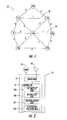
- FIG. 2is a more detailed block diagram illustrating a wireless mobile node in accordance with the present invention.
- FIG. 3is a diagram illustrating a frame of time slots in accordance with the present invention.
- FIG. 4illustrates the scheduling of available time slots to the network diagram illustrated in FIG. 2 in accordance with the present invention.
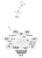
- FIG. 5is a top-level state diagram for the scheduling of semi-permanent time slots and available time slots in accordance with the present invention.
- FIG. 6is a diagram illustrating a semi-permanent time slot scheduling process in accordance with the present invention.
- FIG. 7is a diagram illustrating a semi-permanent time slot being scheduled for a new communication link in accordance with the present invention.
- FIG. 8is a diagram illustrating an available time slot scheduling process in accordance with the present invention.
- FIG. 9is a diagram illustrating an available time slot being added to a communications link in accordance with the present invention.
- FIGS. 10 and 11are diagrams illustrating a semi-permanent time slot being scheduled for a new communications link based upon multiple simultaneous antenna beams from a phased array antenna in accordance with the present invention.
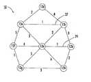
- a wireless mobile communication network 10comprises a plurality of wireless mobile nodes 12 a - 12 h .
- Each mobile node 12 a - 12 hcomprises a transceiver 14 , a directional antenna 16 connected to the transceiver, and a controller 18 connected to the transceiver.
- the controller 18includes a semi-permanent time slot unit 18 a for scheduling a respective semi-permanent time slot for each time frame for establishing a communication link with each neighboring mobile node while leaving at least one available time slot in each time frame.
- An available time slot unit 18 bschedules the at least one available time slot to also serve the communication link with a neighboring mobile node based upon link communications demand.
- the controller 18includes an antenna aiming unit 18 c for aiming the directional antenna toward each neighboring mobile node during communication therewith.
- the semi-permanent time slot unit 18 amay initiate one or more semi-permanent time slot requests for respective time frames to establish the communication link with each neighboring mobile node and leaving at least one available time slot in each time frame, while processing multiple received semi-permanent time slot requests from neighboring mobile nodes.
- the available time slot unit 18 bmay initiate one or more available time slot request to also serve the communication link with the neighboring mobile node based upon link communications demand, while processing multiple received available time slot requests from neighboring mobile nodes.
- a nodecan have one or more pending demand available requests and semi-permanent requests that it initiated while processing multiple received requests. This may sometimes result in temporarily allocating a given time slot to more than one neighbor. However, this conflict may be eliminated by confirmation messages which indicate the selection of one neighbor node for the time slot, as is discussed in more detail below.
- Reliable confirmation messagesmay be provided with a couple of different approaches.
- An initiating mobile nodetransmits a request for time slots to the receiving mobile node, which transmits a reply to the initiating mobile node.
- the initiating mobile nodetransmits a confirmation to the receiving mobile node, and the receiving mobile node transmits the reply again if the confirmation is not received.
- the receiving mobile nodemay transmit an acknowledgment to the initiating mobile node, and the initiating mobile node transmits the confirmation again if the acknowledgment is not received.
- the controller 18waits a time period to resend another request upon simultaneously sending a request to another mobile node and receiving a request from the other mobile node without receiving a corresponding reply. During this time period, incoming time slot requests may be processed. After the period ends, a new request may be sent to the other node if no request was already received from that node or if no time slot allocation was made to that node. If a delayed request reaches the front of the queue, the controller 18 checks to see if a time slot allocation has already been made to that node. If so, the delayed request is discarded. Also, if the request is destined for a node that is no longer a neighbor by the time the request reaches the front of the queue, the delayed request is discarded.
- An interference detection unit 18 dis included to detect interference in time slots for communication with neighboring mobile nodes.
- the controller 18coordinates the scheduling of time slots based upon detected interference.
- the interference detection unit 18 dmay measure a signal-to-interference ratio and/or a packet error rate.
- the packet error ratemay be based upon cyclic redundancy check (CRC) failures.
- the interference detection unit 18 dmay compare detected interference to a threshold.
- the controllerswitches an order of communication between nodes for a given time slot based upon detected interference, and may also coordinate scheduling of new time slots based upon detected interference after switching the order of communication.
- a traffic coordination unit 18 ecoordinates communication with each neighboring mobile node by allocating time slots to the time slot unit based upon link communications demand.
- the controller 18coordinates the scheduling of time slots based upon based upon allocated time slots.
- the traffic coordination unit 18 emay allocate a bulk set of time slots based upon an increased link communications demand, and/or may request a bulk set of time slots from neighboring mobile nodes based upon an increased link communications demand. Also, the traffic coordination unit 18 e may increase a maximum number of time slots, reallocate time slots, and/or allocate half time slots based upon increased link communications demand.
- Such increased link communications demandmay include streaming video and/or high rate sensor data.
- the wireless mobile nodes 12 a - 12 hare operating in a mobile environment. These systems may be ground based and/or airborne, whereby they are continuously entering into and dropping out of the network 10 .
- the directional antenna 16may be a phased array, a dish or horn antennas, for example. Transmission via a directional antenna 16 enables the RF signal to be focused in a desired direction.
- additional communication linksmay be established between other wireless communication systems within the same scheduled semi-permanent time slot. This is illustrated by communication link 27 operating in time slot 1 between mobile nodes 12 c and 12 e , and communication link 29 also operating in time slot 1 between mobile nodes 12 a and 12 b , as best illustrated in FIG. 1 .
- This feature of the present inventionadvantageously allows the resources of the wireless mobile communication network 10 to be better utilized.
- the controller 18limits the number of communication links for each wireless mobile node 12 a - 12 h within each time frame based upon a total number of time slots within the frame.
- the advantage of limiting the number of communication links to a fraction of the total number of time slots within the time framesignificantly simplifies the scheduling of time slots with neighboring nodes.
- the number of communication links for each wireless mobile node 12 a - 12 h within each time frameis less than or equal to N, and the total number of time slots within each frame is greater than or equal to 2N ⁇ 1.
- this type of distributed schedulingavoids conflicts.
- Distributed schedulingallows any two pair of wireless mobile nodes, such as 12 a and 12 b , for example, to schedule a semi-permanent time slot without having to communicate with any other wireless mobile node.
- the controller 18may prioritize the communication links and drop one of the communication links based upon the prioritization for making available a semi-permanent time slot for establishing a communication link with a new neighboring mobile node. Prioritization of the communication links will be addressed in greater detail below. In addition, the controller 18 may also prioritize the communication links and schedule the at least one available time slot based upon this prioritization.
- the controller 18may also schedule one of the semi-permanent time slots as an available time slot if a number of the communication links is less than N. This advantageously supports communication link demands on an as needed basis for the existing communication links. However, the controller 18 may reschedule the demand assigned time slot back to a semi-permanent time slot if the number of the communication links is again equal to N, as will also be discussed in greater detail below.
- Each communication linkis formed by an initiating mobile node, such as node 12 a , and a receiving mobile node, such as node 12 b , and the initiating mobile node transmits a list of available semi-permanent time slots to the receiving mobile node.
- the receiving mobile node 12 bthen transmits selection of one of the semi-permanent time slots to the initiating mobile node.
- the initiating mobile node 12 athen confirms selection of the selected semi-permanent time slot to the receiving mobile node.
- Each mobile nodemay further comprise an omni-directional directional antenna 20 connected to the transceiver 14 for exchanging positional information with other neighboring mobile nodes.
- Other information that may be exchangedincludes resource requirements and detection of the presence of a potential new neighbor node.
- the phased array antenna 16may simultaneously generate multiple antenna beams, wherein the controller 18 aims the phased array antenna to multiple neighboring mobile nodes within a scheduled semi-permanent time slot.
- the interference detection unit 18 ddetects and avoids interference for collinear node pairs within the beamwidth and allocated the same time slot. For example, referring to FIG. 1 , nodes 12 a and 12 e transmitting to nodes 12 b and 12 c , respectively during their half of the same assigned time slot 1 . With wide enough antenna beamwidths, both nodes 12 b and 12 c may simultaneously hear transmissions from both nodes 12 a and 12 e.
- the interference detection unit 18 dmay measure the Signal-to-Interference Ratio (SINR) at the physical layer during time slot usage. Alternatively, the packet error rate can be measured at the link layer based upon CRC check failures. If these measurements violate a specified threshold, the slot may be declared bad.
- SINRSignal-to-Interference Ratio
- the traffic coordination unit 18 emanages unbalanced traffic loads that may be generated by streaming video or high rate sensor data. Coordination mechanisms are provided to permit each half-duplex link to allocate a time slot in any Tx/Rx split of traffic. Also, the maximum number of time slots may be increased to a number above the minimum to create more demand time slots. Subslotting would permit an effective increase or decrease in the maximum number of time slots as nodes may “steal” subslots from a semi-permanent allocated time slot to reallocate to a demand time slot.
- a reservation protocolcould be used together with link scheduling procedures to indicate allocation of resources for a high rate stream at each node along a path from a source to a destination node by requesting and allocating a bulk set of time slots and/or subslots at each node along the path to accommodate the high rate stream.
- link scheduling proceduresto indicate allocation of resources for a high rate stream at each node along a path from a source to a destination node by requesting and allocating a bulk set of time slots and/or subslots at each node along the path to accommodate the high rate stream.
- For reserved resourcesseparate queues and a queue service discipline may be necessary to insure that the capacity required by the stream is delivered.
- the inventionis also directed to a method for establishing communication links for a plurality of mobile nodes 12 a - 12 h, with each mobile node comprising a transceiver 14 , a phased array antenna 16 connected to the transceiver, and a controller 18 connected to the transceiver.
- the methodcomprises for each mobile node 12 a - 12 h scheduling a respective semi-permanent time slot for each time frame to establish a communication link with a neighboring mobile node and leaving at least one available time slot in each time frame.
- the at least one available time slotis preferably scheduled to serve the communication link with a neighboring mobile node based upon link communications demand.
- the phased array antenna 16is aimed toward each neighboring mobile node 12 a - 12 h during communication therewith.
- Each time framemay have up to N semi-permanent time slots and at least 2N ⁇ 1 available time slots.
- the methodmay also include initiating one or more semi-permanent time slot requests for respective time frames to establish a communication link with each neighboring mobile node and leaving at least one available time slot in each time frame, while processing multiple received semi-permanent time slot requests from neighboring mobile nodes, and initiating at least one available time slot request to also serve the communication link with a neighboring mobile node based upon link communications demand, while processing multiple received available time slot requests from neighboring mobile nodes.
- the directional/phased array antenna 16is aimed toward each neighboring mobile node 12 a - 12 h during communication therewith, interference is detected in time slots for communication with neighboring mobile nodes, and the scheduling of new time slots is coordinated based upon detected interference.
- the interference detection unit 18 dmay measure a signal-to-interference ratio and/or a packet error rate. The packet error rate may be based upon cyclic redundancy check (CRC) failures. Also, the interference detection unit 18 d may compare detected interference to a threshold.
- the controller 18switches an order of communication between nodes for a given time slot based upon detected interference, and may also coordinate scheduling of new time slots based upon detected interference after switching the order of communication.
- communication with each neighboring mobile node 12 a - 12 hmay be coordinated by allocating time slots for scheduling based upon link communications demand.
- the methodfurther includes having each node prioritize the communication links and drop one of the communication links based upon the prioritization for making available a semi-permanent time slot for establishing a communication link with a new neighboring mobile node.
- an available time slot that is currently scheduled to serve a particular communication linkmay be reassigned to another communication link based on link demand. This advantageously allows any mobile node to accommodate variations in communication link demands.
- the directional antenna 16is a phased array antenna.
- a phased array antenna 16includes a plurality of antenna elements and respective phase shifters that can be adjusted for producing a steerable antenna beam in a desired direction.
- the phased array antenna 16steers or scans the antenna pattern without physically moving the antenna.
- This overhead channelcan be used for node discovery, net entry, and exchange of various other data link control overhead information including resource requests.
- This overhead channelis provided via an omni-directional antenna 20 .
- Good global timing referenceis also known at all nodes.
- the terms wireless mobile nodes and wireless mobile communications systems 12 a - 12 hare interchangeable throughout the following discussion.
- the wireless mobile communication network 10also includes the capability for locating and tracking mobile nodes so that the phased array antennas 16 can be pointed accurately when a scheduled time slot is available. As noted above, a detailed discussion on the pointing/tracking will not be provided herein.
- phased array antennas 16have zero beamwidth. This assumption will be relaxed later. Consequently, we can assume that a transmission by a given mobile node will be received only by the neighbor mobile node to which it is attempting to transmit. This allows a less restrictive set of constraints on the scheduling of time slots. Each communications link will be labeled with a number which represents a scheduled time slot for transmitting and receiving data therein.
- No nodemay have more than one communications link labeled with the same time slot number.
- a given time slot assignmentwill apply to a half duplex link between two mobile nodes, and be used alternately by the two nodes for transmit and receive.
- FIG. 1shows a network 10 with link connectivity based upon scheduled time slots.
- the time slotsare scheduled so that the wireless mobile nodes 12 a - 12 h know when to point their respective phased array antenna 16 toward a neighboring wireless mobile node.
- the communication linksare assumed to be bidirectional and are used in a half duplex fashion where each time slot number represents a time slot and a transmission opportunity in each direction occurring in that time slot.
- FIG. 3illustrates a representative frame of time slots.
- each epoch or framehas n slots and the value of n is set to N frame .
- a time slotis used for the link connecting to nodes labeled as nodes A and B.
- Each time slotis divided into two mini-slots 22 a , 22 b .
- the first mini-slot 22 a(e.g., half of the time slot) is used for transmissions from node A to B.
- the direction of the linkis reversed and the second mini-slot 22 b is used for transmissions from node B to A.
- each mini-slot 22 a , 22 balso contains a guard time 24 a , 24 b selected according to the following considerations.
- the maximum range between any pair of nodesdetermines the maximum propagation delay that must be accommodated.
- a maximum range of 100 milescorresponds to about 0.5 ms of propagation delay.
- a guard timeis allocated for each mini-slot 22 a , 22 b to accommodate uncertainty of propagation delay and unequal propagation delays between all pairs of nodes.
- a guard time of 0.5 msis needed.
- the guard time allocation for a maximum range of 100 milesimplies the need to make the mini-slots 22 a , 22 b on the order of 2 to 4 ms to minimize the channel efficiency loss.
- a 4 ms mini-slotimplies 200,000 bits/mini-slot (250 mini-slots per second). Then the mini-slot would contain a 25,000 bit guard time and 175,000 bits of mission data.
- the controller 18may also bias each established link to assign priority when the available time slots are scheduled.
- SPsemi-permanent
- DAdemand assigned
- a stated objectiveis to increase reuse of time slots among several nodes at the same time. While the mobile network 10 in FIG. 1 is limited in the total number of nodes and communication links, there are a number of cases of parallel usage of time slots. For example, time slots 1 and 2 are simultaneously each used on 3 different communication links, and time slot 6 is used on only one link. All the other time slots are assigned to two communication links.
- a lower bound on the value of N frame for any graphcan be determined by noting that each node requires at least as many time slots as the node has neighbors, i.e., the node requires a number of time slots at least equal to its degree. Then N frame must be at least as great as the maximum node degree over the entire graph.
- N framedenoting the degree of node i by d i the lower bound on N frame is N frame ⁇ max i ⁇ d i ⁇ (2)
- the reuse portionis assigned the scheduling with N frame equal to the minimum number of time slots that must be used according to equation (2). Note that several nodes, namely all nodes but node 1 , are assigned less than the full set of time slot.
- an enhanced scheduling algorithmmay be able to assign additional slots to some of the links without introducing conflicts in scheduling.
- phased array network problemfocuses primarily on the scheduling of time slots for generating the link schedules.
- Other parts of the overall phased array network problem that ultimately must be addressedinclude: 1) node and neighbor discovery, 2) net entry, 3) overhead channel format and protocol including protocol exchanges for scheduling updates, and 4) tracking and location of neighbor nodes (may include assistance of phased array antenna 16 ), and 5) a routing algorithm for a dynamic network topology.
- the approach for scheduling time slots according to the present inventionis based upon the following principles.
- SPsemi-permanent
- DAavailable time slots
- This limit on the maximum number of semi-permanently assigned time slotsis established. This limit is a parameter that is selected based upon a specific network. This limit is also the upper limit on the number of allowable neighbor nodes, with a single SP time slot per node.
- a limit on the maximum number of time slots per frameis established. This limit is a parameter that is also selected based upon a specific network. This limit is important for establishing a limit on latency since it determines the maximum revisit time for a link transmit opportunity.
- the relationship between the number of total time slots per frame, N frame , and the limit on the maximum number of semi-permanently assigned time slots per frameis chosen so that the scheduling of the semi-permanently assigned time slots is greatly simplified and scheduling conflicts may be significantly avoided even with distributed scheduling.
- each node 12 a - 12 h in the network 10are connected by directional links, where each node has a single beam phased array antenna 16 with beam sharing by time hopping and pointing to its neighbor nodes. Further, assume that the number of neighbors is equal to N, and the limit on the allowable number of semi-permanent time slots (with one SP time slot allocated per neighbor) is fixed.
- N frameincreases for a fixed value of N, there are fewer constraints on the ability of a node to select a time slot that does not conflict with a neighbor's choice of a time slot.
- a node selecting a time slot for a new linkmust select a time slot that it is not currently being used and that the neighbor is not currently using.
- a nodecurrently has m neighbors with a single time slot assigned to each of these links to the neighbors and is adding a link to a new neighbor node, then the neighbor node can be using at most (N ⁇ 1) time slots.
- N frameis greater than (m+N ⁇ 1), then there will be at least one more time slot available that the node can assign to the new link.
- the worst case in this assignment processis when the node already has (N ⁇ 1) neighbors and is assigning the time slot for the N th neighbor node. In this case N frame must satisfy equation (3) for an additional time slot to be guaranteed to be available for assignment to the link to the N th neighbor.
- a nodeneed only coordinate the selection of the semi-permanent time slot to be assigned for a directional link to a neighbor with that neighbor.
- the node requesting the linkmight, for example, send to the neighbor the list of suggested time slots for the link. This is based upon those time slots not being used for SP assignments. There could be some ordering of this list based upon other factors to be discussed below, but this is not necessary.
- the neighbor nodecan then select from this list the time slot it prefers and return a reply with this selection. This allows us to define a straightforward, fully distributed algorithm for scheduling the semi-permanent time slots.
- topology control problemFor certain networks with very large numbers of nodes where the number of potential neighbors will be much larger than the limit N, there will also be a topology control problem to deal with.
- the nodewill be faced with choosing, from among the potential neighbors, those neighbors that create the optimum network topology.
- This topology control problemalso is related to the concept of optimizing an energy efficient network.
- a topology control functioncan be used to select the neighbor node to connect to.
- each nodewill be allowed to have a maximum of N semi-permanent time slots and a total of (2N ⁇ 1) time slot assignments.
- the demand assigned time slotswill be assigned on a basis to best accommodate the traffic load.
- assigning a much larger value of N frameis also an option. In this case, there will be many more time slots available for demand assignment. There may be applications for which this is a desirable way to configure the network.
- the nodeneed only coordinate the selection of the available time slots to be assigned for a directional link to a neighbor with that neighbor. This means that a neighbor will send a request to the neighbor for the time slot assignment over the directional link, and receive either a grant of the assignment or a denial of the request over the same link.
- a node requesting the allocation of an available time slot DA from a neighbor nodewill do so based upon a perceived need for additional capacity on that link. This may be prompted by a high link utilization (queue buildup) based on short and long term measurements.
- the requestwill contain the number of slots requested and a metric, which indicates the priority to be attached to the request.
- the metricmight indicate the queue length as a measure of the need for the time slot allocation.
- the node receiving the requestmay also receive requests from other neighbor nodes, which may contend for allocation of the same time slot.
- a nodeIn order to simplify the protocol, a node must complete processing one thread of an available time slot DA allocation before considering the next allocation. These allocations may not persist for a long period of time because they are constantly subject to preemption to become reallocated as semi-permanent time slots as a result of topology changes or subject to reallocation due to shifting traffic demand.
- the distributed link scheduling algorithmrequires support from an omni-directional overhead channel for certain protocol exchanges that must occur with a potential neighbor node prior to the establishment of the directional link with that node.
- Such messagesinclude the REQ_SPTS which requests the allocation of a semi-permanent time slot on the directional link to that node.
- the omni-directional overhead channelmust support the function of neighbor and link discovery. This is usually done through periodic omni transmissions by each node via an omni-directional antenna 20 that alerts any other node that move within range that the two nodes can be neighbor nodes.
- Several ad hoc routing protocols(including OLSR) have defined such a supporting protocol. These previously defined protocols could be adapted to support this distributed link scheduling algorithm. The primary function that must be performed by such a protocol is to discover new potential neighbor nodes and to report these to the topology control function.
- node and link discoveryincludes each node periodically transmitting beacon messages over the control channel to notify neighbor nodes of its presence and its position.
- link state messagesare transmitted periodically to notify neighbor nodes of the identity of its beacon neighbors (BN list) and its PA neighbor nodes (PAN list) and the time slots assigned to these nodes.
- the link discovery portion of the algorithmcontinually compares the bi-directional beacon neighbors (BBN) list with the PAN list to see if there are any nodes on the BBN list that are not on the PAN list. Any such neighbor node becomes a candidate for link testing to determine if a PA link is possible.
- BBNbi-directional beacon neighbors
- Any such neighbor nodebecomes a candidate for link testing to determine if a PA link is possible.
- the directional linkis tested to determine if reliable communication is possible. If communication is reliable, the new neighbor node is added to the PAN list.
- One approachis to do it this way or another approach is to wait until an SP time slot is assigned and test it in this time slot.
- the topology control functioncan be a very straightforward function if it does not have to do topology optimization.
- the purpose of this functionis to take the list of nodes in the PAN list, the information about the reliability of these links, and the information about the network topology, and use this information to determine which nodes on the PAN list should become PA neighbors. This is the function that should optimize the network topology if there are constraints such as the number of PA neighbors that do not allow all nodes in the PAN list to become PA neighbors.
- Nthe maximum number of semi-permanent time slots per node
- Nthe maximum number of semi-permanent time slots per node
- the topology control functionshould create a neighbor priority (NP) list, which is the PAN list ordered in order of desirability as potential PA neighbors. This list will direct the priority order in which potential PA neighbors are scheduled time slots.
- NPneighbor priority
- our initial problemis that of a small network with perhaps 15 nodes. In this case, we could specify N to have a value in the range of 5 to 8 and still have low latency. There is very little likelihood that there will be any topology utilization issues since allowing for 5 to 8 neighbor nodes will allow almost all possible neighbors to be PA neighbors.
- a second purpose of the topology control functionis to generate the topology change event that causes the link scheduler process to change state and perform the reallocation process for the SP time slots.
- a top-level scheduling algorithm structurewill now be discussed.
- the scheduling processwas formulated with the objective of minimizing the complexity of the process while taking advantage of the overall approach outlined above.
- a key to controlling this schedulingis maintaining an accurate data structure at each node reflecting the state of time slot schedules for future time slots assigned to the link with each neighbor node.
- TABLE 1Two data structures are proposed: a slot assignment DB and a link message DB.
- the possible states of links in the data structure for a given time slot in the epochare listed in TABLE 1.
- the tabledescribes each possible state and gives the notation for that state.
- sub-slot 1would be an allocation to a link of time slot k on the odd numbered frames.
- sub-slot 2would indicate an allocation of the time slot on the even numbered frames.
- the top-level state diagram for the link scheduling protocolis shown in FIG. 5 .
- the diagramshows two independent processes 30 and 32 that are responsible for maintaining and modifying the time slot allocation database.
- On the left sideis the state diagram for the process for maintaining and assigning semi-permanent (SP) time slots, i.e., process 30 .
- SPsemi-permanent
- This processhas priority over the assignments made by the process 32 on the right, which has responsibility for assigning the available (DA) time slots.
- the time slots that can be seizedare as follows: free, DA allocated, and in process of being DA allocated.
- the time slots that can be seizedare as follows: free, DA allocated and also need to be reallocated.
- This databasemust be controlled as a locked database such that for any given time slot assignment state, only one of the two scheduling processes may modify that state at a given point in time. Once one of the processes begins to modify the state of a particular time slot assignment, the state is locked and the other process may not modify it until it is released.
- each time slot in the DBis in one of seven states as indicated in TABLE 1. Available time slots are said to be in the free state, i.e., they are not assigned to a link to one of its neighbor nodes either because a scheduling conflict has prevented assignment or because the time slot has recently become free and has not yet been scheduled.
- a time slot in the free statemay be scheduled either as an SP time slot or a DA time slot.
- a time slot that has been allocated as SP assignedmay be modified only by the process that maintains SP time slots.
- the time slotmay be deallocated by this process if network topology changes or if a more desirable topology is possible. Until such a time slot is returned to the free state, the process for maintaining and assigning the DA time slots cannot modify its state.
- any time slot with a DB state indicating that it is in the process of being SP assignedcannot be allocated by the DA assignment process. This includes states indicating that SP request and reply messages have been sent. However, if the state of a time slot is DA allocated, then it may be reallocated by the DA assignment process. This might be done if the loading on the network indicated that a reallocation of the DA time slot is needed.
- the process allocating SP time slotshas priority.
- itmay seize and reassign all time slots that have been DA assigned or are in the process of being DA assigned. This is done to provide a straightforward process of ensuring at least a single SP time slot assigned to each neighbor node during a frame of N frame time slots.
- SP allocated time slotsare returned to the free state only if the link is lost or if the topology control function determines that a particular link should no longer be in the list of the top N links to be established with neighbor nodes.
- FIG. 5illustrates how this process works at the top level.
- the SP slot assignment processhas greater flexibility in allocating time slots. It can seize more time slots for allocation than the DA process, and it can seize time slots that either have been DA allocated or are in the process of being DA allocated.
- the SP processmay receive various events for processing including topology change events from the topology control function and protocol messages.
- Such eventsmight include loss of link to a neighbor, discovery of a new neighbor, reception of an SP allocation request message from a neighbor node, and the discovery that a topology change should occur to either add a link to a neighbor, break a link, or do both.
- the topology change event notificationwill carry data that will describe the topology change that needs to occur.
- the SP slot assignment processinitiates protocol message exchanges with the new neighbor node and modifies the slot assignment DB. This ultimately results in the agreement between the two nodes on a time slot assignment for the SP slot assigned to this link. Only a single SP time slot is to be assigned to each link with a neighbor to simplify the protocol. Additional details of this protocol are described below.
- the process of assigning DA time slotsfollows a similar procedure.
- the DA slot assignment processmust calculate the DA time slot needs and compare them with the allocated time slots to determine if a new time slot reallocation is needed. If a reassignment of DA slots is initiated, it will also lead to a series of protocol message exchanges with neighbor nodes to agree on the reassigned time slots.
- the DA slot assignment processmay reassign only time slots that are in the free state or not SP assigned. More about the protocol details and the process for determining when DA time slot reassignment is needed will be discussed below.
- Nis fixed and intelligently chosen with respect to the network size and environment.
- N frame2N ⁇ 1.
- N framecould also be set at any value higher than this to provide additional on-demand time slots if that is deemed to be useful for the particular network and traffic environment.
- the neighbor priority (NP) listis generated by the topology control function and is used to indicate the preferred PA neighbor nodes for the assignment of time slots.
- the topology control functionwill generate topology change events to the SP slot assignment process to make it attempt to get time slot assignments to all of these neighbor nodes. If the length of the NP list is greater than N, then it will generate topology change events to the SP slot assignment process to obtain time slot assignments to each of the N highest priority nodes on the NP list.
- the NP listis constantly changing due to network dynamics.
- the nodeis removed from the NP list and the time slot(s) for that link are then subject to reallocation. This is initiated by the topology control function which sends the SP slot assignment process a link delete event.
- the SP time slot and any DA time slots allocated to that linkbecome available for reallocation to another node on the PA list.
- the first choice when slots become availableis to allocate the slot(s) to additional PA neighbor nodes if that is possible given the current state of the NP list. If no additional neighbor nodes can be added, then the slot(s) can be reallocated on a DA basis.
- FIG. 6shows a state diagram of the SP slot assignment process.
- a link scheduling message DBis created as shown in TABLE 3. This maintains the state needed from prior protocol exchanges to be used when the next SP message arrives for processing.
- the idle processdoes event management in that it checks received events prior to allowing a state change to one of the other states.
- These operationsinclude checking received messages to determine if they are consistent with the current state of the DB. If a message is inconsistent with the DB, it is discarded. Certain timeouts may indicate that DB state needs to be reset. This process performs this function.
- FIG. 7An example of SP time slot assignment is shown in FIG. 7 .
- Nodes 1 and 2both have 3 neighbors with the SP time slots allocations shown for each link. Therefore, they can add an additional link between themselves.
- the link scheduling protocolwill find an acceptable time slot for the SP allocation.
- the corresponding protocol message exchangeis shown in TABLE 5.
- Node 1is using slots 1 , 2 and 3 for SP allocations to its neighbors so its list L contains the other time slots 4 , 5 , 6 and 7 .
- the request messageis sent, the appropriate changes are made to the time slot and link scheduling message data structures.
- Node 2is using time slots 4 , 5 and 6 as SP allocations for its links to its 3 neighbors so it selects time slot 7 as the only one that will work for the new link. It sends this choice in the reply message.
- Received messagesare first checked versus the link scheduling message DB to insure that the message is consistent with the current state of the DB. For example, if we sent a request to a neighbor, the next message expected is a reply. To simplify this distributed protocol, only one thread of SP protocol message exchanges is allowed at a time. This is enforced in the procedure by checking the DB to see if other SP message exchanges are ongoing prior to initiating a link add transition or prior to processing a REQ_SPTS message.
- the list of candidate time slotsmust contain at least N time slots including at least one semi-permanent time slot SP.
- the listcan also include possibly all of the N ⁇ 1 available DA time slots.
- the available or on-demand time slotsmay be currently temporarily allocated for on-demand traffic. This list will be priority-ordered to indicate the time slot preference that causes the least perturbation in the current available time slot assignments. In other words, the notation being used is that a time slot is not an SP time slot unless already allocated to a communication link. Any of the 2N ⁇ 1 time slots may be an SP time slot.
- the list of N time slots sentare all either free time slots or an available DA time slot. These may be N ⁇ 1 SP time slots-but they are already allocated and are not on the list.
- the REQ_SPTS messagecan be sent up to MAX_TRIES times to allow for unreliable links and conflicts with other assignments potentially occurring simultaneously.
- the timeout in the link scheduling message DBtriggers the retries if there is no REPLY_SPTS message from the neighbor node in response to the REQ_SPTS message. Once the REQ_SPTS message is sent the process returns to the idle state where other events can be processed.
- the neighbor receiving a REQ_SPTS messagewill have its SP slot assignment process transition to the process REQ_SPTS state.
- the procedure for processing this messageis shown in TABLE 8. This procedure takes the offered list of time slots, Ls, and selects its preferred time slot, Ns.
- the procedureselects the time slot it prefers from this list. Then a REPLY_SPTS reply message with this selection is sent. If the link cannot be accepted or if there is another ongoing SP slot assignment in process, a negative REPLY_SPTS reply message is sent.
- the selected time slotwill be selected from one of its N available time slots or one of its free time slots.
- An available time slotis either a “free” time slot or an available DA time slot. There will be at least N of these if we can add another link.
- Each nodealways manages its time slots so that there are N time slots available to assign as semi-permanent time slots (one to each of N neighbor nodes if that many neighbor nodes are available). If it accepts the link, then it will have at most N ⁇ 1 other neighbor nodes with one semi-permanent time slot allocated per node.
- the procedurealso makes the appropriate modifications to the state in the link scheduling message DB and the slot assignment DB.
- a received REPLY_SPTS messageis processed as shown in TABLE 9.
- the choice of time slot, Ns, received from the neighbor nodeis extracted from the message.
- This three-way handshakeeliminates uncertainty in the outcome of the scheduling process.
- the choice of time slot, Nsis examined to see if it is still an allowable assignment for a new SP time slot for the new link. If it is allowable, then the appropriate modifications to the state in the slot assignment and link scheduling message databases are made. Then a positive CONFIRM message is returned.
- the slot assignment and link scheduling message databasesare reset for this Nbr_ID. Otherwise, if the choice of Ns is no longer allowable, then the link scheduling message database is reset for this Nbr_ID. Then a negative CONFIRM message is sent to the neighbor node rejecting the link.
- Table 10shows the procedure for processing CONFIRM messages. If the CONFIRM is positive, the link is considered to be added to the set of neighbors. The number of links for the node, Num_links, is incremented. The assigned time slot, Ns, is marked SP_Alloc in the slot assignment DB, and the link message state in the link scheduling message DB is reset for index Nbr_ID. If the message was a negative CONFIRM, then the slot assignment and link scheduling message databases are reset for this Nbr_ID.
- An allocated time slotmay need to be deallocated for one of several reasons. If during the course of normal operation a link goes down or becomes unreliable, then the topology control function gets involved to address the unreliable link problem. ultimately, it may generate a topology change (e.g., link deletion) event directing the SP slot assignment process to delete all slots assigned to the link.
- a topology changee.g., link deletion
- the steps involved in this procedureare shown in TABLE 11.
- the linkis de-allocated by sending a DELETE_TS message from the node requesting the de-allocation of all the time slots which are shared with the other node.
- the appropriate entries in the link scheduling message DB and the slot assignment DBare reset.
- Table 12shows the procedure for processing a received DELETE_TS message.
- the list of deallocated time slots, Ls,is extracted from the message. Then the appropriate state in the slot assignment DB and in the link scheduling message DB is reset.
- the objective for the function allocating the semi-permanent time slotsis to connect to as many neighbor nodes as possible up to N. If N neighbor nodes are obtained, then each is allocated a single semi-permanent time slot. Once a new link is established by this protocol, both nodes will commence operation in the newly allocated SP time slot.
- This operationwill test the new link to determine if reliable communication can be maintained using the allocated time-slot. This insures that there is no unusual interference that occurs in this particular time slot. If the link is tested as unreliable, then the topology control function will be notified so that the time slot can be deallocated and used for other purposes.
- the available time slotsare to be allocated in a manner that is responsive to the fluctuating demands of network traffic.
- Nis fixed and intelligently chosen with, respect to the network size and environment.
- N frame2N ⁇ 1.
- a request for available time slots from one node to a neighbor nodeis allowed only if at least one semi-permanent time slot is allocated for the link between these two nodes.
- a nodemay request a periodic allocation of a single time slot every m s th (or second) frame.
- the messages used for scheduling the available time slotscan be sent over the PA link for scheduling time slots several frames in advance of when they are needed since the link has an allocation of at least one semi-permanent time slot per frame.
- T iksethe measured average traffic sent over link (i, k) (in units of the number of time slots per frame) will be denoted by T ikse . This measure will include all traffic sent over one or more semi-permanent time slots per frame as well as any available time slots.
- T ik needmax( T ik dem , T ik dem ) (5)
- M ik DAT ik need ⁇ N ik tot +B, (6) which is a measure of the estimated number of additional time slots that should be allocated to this link through the DA slot allocation mechanism.
- Bis a bias term that might be nominally set at about 1 ⁇ 4 to 1 ⁇ 2 of a time slot to allocated enough excess capacity to each link to avoid significant queuing. While we are illustrating the approach using the metric defined in (4), a variety of other forms of metric could also be used as the basis for allocating the DA time slots.
- FIG. 8shows a state diagram of the DA slot assignment process 36 .
- the state diagram and the protocol exchangesare similar to those of the SP slot assignment process.
- only a single thread of DA time slot allocationcan be in process at any time.
- the idle processdoes event management in that it checks received events prior to allowing a state change to one of the other states.
- Node 2When the request message is sent, the appropriate changes are made to the time slot and link scheduling message data structures.
- Node 2is using time slots 1 , 3 and 6 as SP allocations for its links to its 3 neighbors and sub-slots 2 . 1 and 3 . 2 as DA allocations. It can select either sub-slot 4 . 2 or both sub-slots of slot 5 . It chooses and sends this choice in the reply message.
- each network nodeuses these measures to allocate the (N ⁇ 1) available time slots for directional links to neighbor nodes.
- each nodewill continuously maintain the link metric, M ik DA , for each of its links allocated a semi-permanent time slot.
- M ik DAlink metric
- Each nodewill use this link metric to indicate the need for additional transmission time slots to each neighbor node.
- the largest values of M ik DAindicate the links with the greatest need for additional on-demand time slot allocation.
- a positive value of M ik DAindicates the number of additional time slots required, and a negative value of indicates the number of time slots that can be surrendered for reallocation.
- M ik DAAs the metrics, M ik DA , are maintained, if the largest link metric indicates a need for an additional sub-slot allocation and if there are sub-slots available either as free slots or as excess DA allocation to other links (again indicated by a small metric), then the process transitions to the add DA slot state and the process of finding a DA sub-slot allocation is initiated.
- the nodeneed only coordinate the selection of the DA time slot to be assigned for a directional link to a neighbor with that neighbor. This means that a neighbor will send a request to the neighbor for the time slot assignment over the directional link, and receive either a grant of the assignment or a denial of the request over the same link.
- Received messagesare first checked versus the link scheduling message DB to insure that the message is consistent with the current state of the DB. For example, if we sent a request to a neighbor, the next message expected is a reply.
- Link metricswill be recalculated periodically according to a preset-schedule.
- a link which has a link metric greater than a certain threshold, Max_metric_threshold,is a candidate for obtaining a new DA sub-lot.
- the link with the maximum metric that exceeds this thresholdwill be selected as the next link to which a new DA sub-slot is allocated.
- a new DA sub-slotneeds to be allocated and if it satisfies the above conditions, then a transition to the add DA slot state occurs in the DA slot assignment process.
- the list of candidate time slotsmust contain all free sub-slots and all DA sub-slots with a metric below a certain threshold, Min_metric_threshold.
- the DA time slotsmay be currently temporarily allocated for other DA traffic.
- This listwill be priority-ordered to indicate the sub-slot preference that causes the least perturbation in the current on-demand time slot assignments.
- the priority orderingwill be first the free time slots followed by the sub-slots with the smallest metrics progressing up to the largest metric less than the Min_metric_threshold.
- the neighbor receiving a REQ_DATS messagewill have its DA slot assignment process transition to the REQ_SPTS state.
- the procedure for processing this messageis shown in TABLE 17. This procedure takes the offered list of sub-slots, Ls, and selects its preferred sub-slot, Ns.
- the sub-slot acceptedis the first sub-slot on the list, ls, that is either marked free in the slot assignment DB or is DA allocated with a link metric less than Min_metric_threshold.
- a REPLY_DATS reply messagewith this selection is sent. If the link cannot be accepted or if there is another ongoing DA slot assignment in process, a negative REPLY_DATS reply message is sent.
- the procedurealso makes the appropriate modifications to the state in the link scheduling message DB and the slot assignment DB.
- a received REPLY_DATS messageis processed as shown in TABLE 18.
- the choice of sub-slot, Ns, received from the neighbor nodeis extracted from the message.
- this three-way handshakeeliminates uncertainty in the outcome of the scheduling process.
- the choice of sub-slot, Nsis examined to see if it is still an allowable assignment for a new DA sub-slot for the new link. If it is allowable, then the appropriate modifications to the state in the slot assignment and link scheduling message databases are made. Then a positive CONFIRM message is returned.
- the slot assignment and link scheduling message databasesare reset for this Nbr_ID. Otherwise, if the choice of Ns is no longer allowable, then the link scheduling message database is reset for this Nbr_ID. Then a negative CONFIRM message is sent to the neighbor node rejecting the link.
- TABLE 19shows the procedure for processing CONFIRM messages. If the CONFIRM is positive, the selected sub-slot to be added to the allocation to the link to Nbr_ID. The assigned time slot, Ns, is marked DA_Alloc in the slot assignment DB, and the link message state in the link scheduling message DB is reset for index Nbr_ID. If the message was a negative CONFIRM, then the slot assignment and link scheduling message databases are reset for this sub-slot.
- An allocated time slotmay need to be deallocated for one of several reasons. If during the course of normal operation a link goes down or becomes unreliable, then the topology control function gets involved to address the unreliable link problem. Ultimately, it may generate a topology change (e.g., a link deletion) event directing the SP slot assignment process to delete all slots assigned to the link.
- a topology changee.g., a link deletion
- the steps involved in this procedureare shown in TABLE 11.
- the linkis de-allocated by sending a DELETE_TS message from the node requesting the de-allocation of all the time slots which are shared with the other node with.
- the appropriate entries in the link scheduling message DB and the slot assignment DBare reset.
- Table 21shows the procedure for processing a received DELETE_TS message.
- the subslot, Ls, to be deallocatedis extracted from the message. Then the appropriate state in the slot assignment DB and in the link scheduling message DB is reset.
- the link scheduling algorithmis also applicable to multiple simultaneous beams generated by the phased array antenna 16 .
- all nodesdo not all have to have the same number of beams, i.e., node k has B k beams. This is equivalent to B k parallel links possible at any time slot.
- N beamthe number of semi-permanently (SP) assigned time slots on any one of its B k beams (and therefore the maximum number of allowable neighbor nodes per beam) to be denoted by N beam .
- the value of N beamis dependent only on the number of time slots per frame and not the number of beams.
- N frame⁇ 2 ⁇ N beam ⁇ 1 (7)
- node khas B k beams with beam sharing by time hopping and pointing to its neighbor nodes.
- the number of neighbors allowed per beamis equal to N beam , the fixed limit on the allowable number of semi-permanent time slots allowed per beam (with one SP time slot allocated per neighbor).
- each nodecan select a different semi-permanent time slot for each of these links and each of its beams by mutual agreement with the neighbor for that link without regard to what colors other nodes are selecting more than one hop away. This allows each node to select its N beam semi-permanent time slots for each beam in a very direct fashion by communicating only with its neighbor node. By following this strategy, each node is able to support at least
- N kB k ⁇ N beam (8)
- FIG. 10An example of SP time slot assignment between two nodes with an unequal number of beams per node is shown in FIG. 10 .
- node 1has 2 beams and node 2 has 3 beams. While the two nodes have different numbers of beams, both nodes must use the same frame structure.
- N frame5 time slots per frame. From (7) and (8), this allows node 1 to have a maximum of 6 neighbors and node 2 to have a maximum of 9 neighbors.
- both nodeshave one less than the maximum number of neighbors they are allowed under the constraints of (7) and (8).
- the SP beam/time slots allocationsare shown for each link. These nodes can add an additional link between themselves while still satisfying the constraints of (7) and (8).
- the link scheduling protocolwill find an acceptable beam/time slot for the SP allocation for each node, and it operates in essentially the same way it did with the single beam case.
- node 2sends a list of the 3 SP time slots (available on beam b) to node 2 .
- This listmay include all free and DA time slots on this beam.
- the request messageis sent, the appropriate changes are made to the time slot and link scheduling message data structures.
- Node 2has previously allocated SP all available SP time slots on beams a and b for its links to its 8 neighbors.
- beam cis the only beam that can accept a new SP allocation.
- the reply messageis sent the appropriate changes are also made to the beam/time slot and link scheduling message data structures.
- the state of the appropriate time slotsare changed to “SP allocated to link (1,2).”
- the algorithmTo offer a new SP time slot to a potential neighbor, the algorithm must first find a beam for which the number of neighbors is less than N beam . This beam can then be used to add the new neighbor.
- the REQ_SPTS message that the node sends to its neighborwill specify N beam available time slots for that beam that are not currently SP allocated.
- the nodeHaving received an REQ_SPTS message the node must find one of its beams for which the number of neighbors is less than N beam . This beam can then be used to add the new neighbor. Comparing the list of N beam time slots in the received REQ_SPTS message with the N beam time slots not currently allocated in the selected beam, at least one time slot can be found that is common to both lists. That time slot can be selected as the time slot to send in the REPLY_SPTS message. Once the originating node receives the REPLY_SPTS message, both nodes will have selected their beam and the common time slot allocation.
- the example problem in FIG. 10has 2 nodes each with 3 beams with each beam operating in a different frequency band, i.e., beams a, b, and c each use a different frequency band. Assume also that the frame size is 5. Both nodes have already committed 7 SP time slots to neighbor nodes and thus, from (9), they can each add an additional neighbor with an SP time slot allowing them to establish a link between them.
- the committed SP time slotsare indicated in the figure, and the message exchanges required to establish the SP time slot assignment and the new link are indicated in Table 23.
- node 2had already allocated 7 beam/time slot combinations that were not used by node 1 (which were in the list of 8 beam/time slot combinations received in the REQ_SPTS message).
- the present inventionthus provides a fully distributed link scheduling algorithm and protocol for phased array networks.
- the description of the algorithm/protocol detailsassumed the case of a single directional beam per node, which is time-shared and pointed toward neighbor nodes during the allocated time slot for that access. However, the approach can be used for an arbitrary number of steered beams per node.
Landscapes
- Engineering & Computer Science (AREA)
- Computer Networks & Wireless Communication (AREA)
- Signal Processing (AREA)
- Quality & Reliability (AREA)
- Mobile Radio Communication Systems (AREA)
- Data Exchanges In Wide-Area Networks (AREA)
- Small-Scale Networks (AREA)
- Time-Division Multiplex Systems (AREA)
Abstract
Description
For the
Nframe≧maxi{di} (2)
For the
Nframe≧2N−1 (3)
| TABLE 1 | |||
| Time Slot State in DB | Notation | ||
| Free | Free | ||
| SP Allocated Time Slot | SP_Alloc | ||
| DA Allocated Time Slot (May | DA_Alloc | ||
| Be Preempted by SP Allocation | |||
| Process or by DA | |||
| Reallocation) | |||
| SP Allocation Request Message | SP_Req | ||
| Sent | |||
| SP Allocation Reply Message | SP_Reply | ||
| Sent | |||
| DA Allocation Request Message | DA_Req | ||
| Sent (May Be Preempted by SP | |||
| Allocation Process or by DA | |||
| Reallocation) | |||
| DA Allocation Reply Message | DA_Reply | ||
| Sent (May Be Preempted by SP | |||
| Allocation Process or by DA | |||
| Reallocation) | |||
| TABLE 2 | |||||
| Assigned | |||||
| Time Slot | Subslot | Neighbor ID | |||
| 1 | — | Free | — | ||
| 2 | — | 3 | |||
| 3 | 4 | ||||
| 4 | 1 | 3 | |||
| 4 | 2 | 4 | |||
| 5 | 1 | 5 | |||
| 5 | 2 | 3 | |||
| 6 | — | SP_Alloc | 5 | ||
| 7 | 1, 2 | DA_Alloc | 8 | ||
| 8 | 2 | 4 | |||
| 9 | — | SP_Alloc | 8 | ||
| TABLE 3 | ||||||
| Time | Selected | |||||
| Link | Time | Slot | Time | Selected | Num— | |
| Nbr_ID | State | out | List | Slot | Subslot | tries |
| 1 | SP_Alloc | — | — | 2 | 1 | — |
| 1 | SP_Alloc | — | — | 2 | 2 | — |
| 1 | DA_Alloc | — | — | 5 | 1 | — |
| 2 | SP_Alloc | — | — | 4 | 1 | — |
| 2 | SP_Alloc | — | — | 4 | 2 | — |
| 2 | DA_Alloc | — | — | 5 | 2 | — |
| 3 | SP_Req | T2 | Ls | — | 1 | |
| 4 | SP_Alloc | — | — | 6 | 1 | — |
| 4 | SP_Alloc | — | — | 6 | 2 | — |
| TABLE 4 | |||
| Message Type | Message Function | ||
| REQ_SPTS | Request New SP Slot Allocation | ||
| REPLY_SPTS | Reply to Received REQ_SPTS | ||
| CONFIRM | Response to Received REPLY_SPTS | ||
| DELETE_TS | Message Indicating Deleted Time | ||
| Slot Allocation | |||
| TABLE 5 | |
| Receives Link Add Event | |||
| From Its Topology | |||
| Control For A Link From | |||
| Send | Msg Lost | ||
| REQ_SPTS(L = (4, 5, 6, 7)) | → | ||
| Timeout and retry | |||
| Resend | → | Rcvd | |
| REQ_SPTS(L = (4, 5, 6, 7)) | REQ_SPTS(L = (4, 5, 6, 7)) | ||
| Rcvd REPLY_SPTS(Slot 7) | ← | Send REPLY_SPTS(Slot 7) | |
| Send CONFIRM(Slot 7) | → | Rcvd CONFIRM(Slot 7) | |
| Slot | 7 Allocated to Link | ||
| (1, 2) | (1, 2) | ||
| TABLE 6 |
| Procedure for Idle State (SP Event Management) |
| Case Event Type | ||
| Received Message: | ||
| If received message is not consistent with the | ||
| state of the Link Scheduling Message | ||
| DB for that Nbr_ID | ||
| Discard Message | ||
| Elseif message type = REQ_SPTS | ||
| If no pending SP message activity in the Link | ||
| Scheduling Message DB for link additions | ||
| other than receiving a previous REQ_SPTS | ||
| message from Nbr_ID | ||
| Transition to Process REQ_SPTS state to | ||
| process message | ||
| Else | ||
| Reject new link and send negative | ||
| REPLY_SPTS message to Nbr_ID | ||
| End | ||
| Elseif message type = REPLY_SPTS | ||
| Transition to Process REPLY_SPTS state to | ||
| process message | ||
| Elseif message type = CONFIRM | ||
| Transition to Process CONFIRM state to | ||
| process message | ||
| Elseif message type = DELETE_TS | ||
| Transition to Process DELETE_TS state to | ||
| process message | ||
| End | ||
| Check Timeouts: | ||
| Check all timeouts | ||
| If Timeout expired for a link in the SP_Req state | ||
| Transition to Link Add State | ||
| If Timeout expired for a link in the SP_Reply | ||
| state | ||
| Reset Slot Assignment DB for time slot Ns and | ||
| in the Link Message state in | ||
| Link Scheduling Message DB for index Nbr_ID | ||
| End | ||
| Link Addition Notification from Topology Control: | ||
| If no pending SP message activity in the Link | ||
| Scheduling Message DB | ||
| Transition to Link Add state to add Nbr_ID | ||
| Else | ||
| Backoff and reschedule Link Addition | ||
| End | ||
| Link Failure or Link Deletion: | ||
| Transition to Link Delete state to delete link to | ||
| Nbr_ID | ||
| End | ||
| End | ||
| TABLE 7 |
| Procedure for Link Addition to Node |
| Nbr_ID (Generate REQ_SPTS Message) |
| If Num_tries = MAX_TRIES (No more tries) | ||
| Reset state of Link Scheduling Message DB for index | ||
| Nbr_ID (Link State = Free and no timeout for retry) | ||
| Return to Idle state | ||
| Else | ||
| If initial try to node Nbr_ID | ||
| Set Num_tries = 1 in Link Scheduling Message DB | ||
| for index Nbr_ID | ||
| Else | ||
| Set Num_tries = Num_tries +1 in Link Scheduling | ||
| Message DB for index Nbr_ID | ||
| End | ||
| Construct list Ls of time slots to offer to Nbr_ID | ||
| Append list Ls to REQ_SPTS message and send to Nbr_ID | ||
| Setup timeout and Link Message state in Link Scheduling | ||
| Message DB for index | ||
| Nbr_ID and in Slot Assignment DB | ||
| Return to Idle state | ||
| End | ||
| TABLE 8 |
| Procedure for Processing REQ_SPTS Message (from Nbr_ID) |
| If Num_links<N | ||
| Examine list Ls of the available time slots received | ||
| from potential neighbor node | ||
| Nbr_ID, compare with the current allocations in | ||
| the Slot Assignment DB, and select the best | ||
| assignment = Ns | ||
| Make appropriate modification to the Slot Assignment DB | ||
| (mark it as SP_Reply) for time slot Ns | ||
| If time slot Ns was DA allocated | ||
| Send DELETE_TS to the neighbor node allocated the | ||
| DA time slot | ||
| End | ||
| Append time slot choice, Ns, to REPLY_SPTS message and | ||
| send to Nbr_ID | ||
| Setup timeout and Link Message state (to SP_Reply with | ||
| time slot Ns) in Link | ||
| Scheduling Message DB for index Nbr_ID | ||
| Return to Idle state | ||
| Else | ||
| Reject new link and send negative REPLY_SPTS message to | ||
| Nbr_ID | ||
| Return to Idle state | ||
| End | ||
| TABLE 9 |
| Procedure for Processing REPLY_SPTS Message from Nbr_ID |
| Extract time slot choice Ns from the REPLY_SPTS message from | ||
| Nbr_ID | ||
| If (positive REPLY_SPTS message) and (choice of Ns is still | ||
| allowable from Slot Assignment DB) | ||
| Make appropriate modification to the Slot Assignment DB | ||
| (mark it as SP_Reply) | ||
| for time slot Ns and in the Link Message state in | ||
| Link Scheduling Message DB | ||
| for index Nbr_ID | ||
| If time slot Ns was DA allocated | ||
| Send DELETE_TS to the neighbor node allocated the | ||
| DA time slot | ||
| End | ||
| Create CONFIRM message for Ns and send to Nbr_ID | ||
| Increment Num_links | ||
| Return to Idle state | ||
| Elseif negative REPLY_SPTS message | ||
| Reset Slot Assignment DB for time slot Ns and in the | ||
| Link Message state in | ||
| Link Scheduling Message DB for index Nbr_ID | ||
| Return to Idle state | ||
| Else | ||
| Reset Link Message state in Link Scheduling Message DB | ||
| for index Nbr_ID | ||
| Send negative CONFIRM message to Nbr_ID | ||
| Return to Idle state | ||
| End | ||
| TABLE 10 |
| Procedure for Processing CONFIRM Message from Nbr_ID |
| If positive CONFIRM message | ||
| Make appropriate modification to the Slot Assignment DB | ||
| (mark it as SP_Alloc) | ||
| for time slot Ns | ||
| Reset Link Message state in Link Scheduling Message DB | ||
| for index Nbr_ID | ||
| Increment Num_links | ||
| Return to Idle state | ||
| Else | ||
| Reset the Slot Assignment DB (mark it as Free) for time | ||
| slot Ns | ||
| Reset Link Message state in Link Scheduling Message DB | ||
| for index Nbr_ID | ||
| Return to Idle state | ||
| End | ||
| TABLE 11 |
| Procedure for Link Deletion to Node Nbr_ID |
| (Generate DELETE_TS Message) |
| Extract list of all SP and DA time slots, Ls, from the Slot | ||
| Assignment DB assigned to the | ||
| link to Nbr_ID | ||
| Construct message, DELETE_TS, with the list, Ls, and send to | ||
| Nbr_ID | ||
| Reset Link Scheduling Message DB for index Nbr_ID and Slot | ||
| Assignment DB for all time slots in Ls | ||
| Decrement Num_links | ||
| Return to Idle state | ||
| TABLE 12 |
| Procedure for Processing DELETE_TS Message from Nbr_ID |
| Extract list of time slots, Ls, from the DELETE_TS message | ||
| from Nbr_ID | ||
| Reset the Slot Assignment DB (mark it as Free) for all time | ||
| slots in list Ls | ||
| Reset Link Message state in Link Scheduling Message DB for | ||
| all time slots in list Ls for index Nbr_ID | ||
| Decrement Num_links | ||
| Return to Idle state | ||
Tikdem=f(Tikse,Qik), (4)
which is a function of the measured traffic plus the estimated additional capacity needed that is indicated by the queue size. Then the number of time slots needed on this link, Tikneed, is as follows:
Tikneed=max(Tikdem, Tikdem) (5)
The metric assigned to this link is as follows:
MikDA=Tikneed−Niktot+B, (6)
which is a measure of the estimated number of additional time slots that should be allocated to this link through the DA slot allocation mechanism. B is a bias term that might be nominally set at about ¼ to ½ of a time slot to allocated enough excess capacity to each link to avoid significant queuing. While we are illustrating the approach using the metric defined in (4), a variety of other forms of metric could also be used as the basis for allocating the DA time slots.
| TABLE 13 | |||
| Message Type | Message Function | ||
| REQ_DATS | Request New DA Slot Assignment | ||
| REPLY_DATS | Reply to Received REQ_DATS | ||
| CONFIRM | Response to Received REPLY_DATS | ||
| DELETE_TS | Message Indicating Deleted Time Slot | ||
| Allocation | |||
| LINK_METRIC | Message Broadcast to Neighbor Nodes | ||
| with Link Metric for Each Link to a | |||
| Neighbor Node | |||
| TABLE 14 | |
| Determines That The | ||
| Link From | ||
| Additional DA Time Slot | ||
| Send | Msg Lost | |
| REQ_DATS(L = (4.2, 5, 6)) | → | |
| Timeout and retry | ||
| Resend | → | Rcvd |
| REQ_DATS(L = (4.2, 5, 6)) | REQ_DATS(L = (4.2, 5, 6)) | |
| Rcvd REPLY_DATS(Slot 4.2) | ← | Send REPLY_DATS(Slot 4.2) |
| Send CONFIRM(Slot 4.2) | → | Rcvd CONFIRM(Slot 4.2) |
| Slot 4.2 DA Allocated | Slot 4.2 DA Allocated | |
| to Link (1, 2) | to Link (1, 2) | |
| TABLE 15 |
| Procedure for Idle State (DA Event Management) |
| Case Event Type |
| Received Message: |
| If received message is not consistent with the |
| state of the Link Scheduling Message |
| DB for that Nbr_ID |
| Discard Message |
| Elseif message type = REQ_DATS |
| If no pending DA message activity in the Link |
| Scheduling Message DB for link additions |
| other than receiving a previous REQ_DATS |
| message from Nbr_ID Transition to Process |
| REQ_DATS state to process message |
| Else |
| Reject new link and send negative |
| REPLY_DATS message to Nbr_ID |
| End |
| Elseif message type = REPLY_DATS |
| Transition to Process REPLY_DATS state to |
| process message |
| Elseif message type = CONFIRM |
| Transition to Process CONFIRM state to |
| process message |
| Elseif message type = DELETE_TS |
| Transition to Process DELETE_TS state to |
| process message |
| End |
| Check Timeouts: |
| Check all timeouts |
| If Timeout expired for a link in the DA_Req state |
| Transition to Add DA Slot state |
| If Timeout expired for a link in the DA_Reply |
| state |
| Reset Slot Assignment DB for time slot Ns and |
| in the Link Message state in |
| Link Scheduling Message DB for index Nbr_ID |
| End |
| Recalculate Link Metrics and DA Time Slot Needs: |
| Recalculate link metrics |
| Send new link metrics to all neighbor nodes in a |
| LINK_METRIC message |
| Sort link metrics and select Largest_link_metric |
| If (no pending DA message activity in the Link |
| Scheduling Message DB) and |
| (Largest_link_metric > Max_metric_threshold) |
| Transition to Add DA Slot state to add new DA |
| slot assignment to Nbr_ID |
| End |
| DA Time Slot Delete: |
| Transition to DA TS Delete state to delete Time |
| Slot to Nbr_ID |
| End |
| TABLE 16 |
| Procedure for Addition of a New DA Subslot to the Link to |
| Node Nbr_ID (Generate REQ_DATS Message) |
| Construct list Ls of time slots (subslots) to offer to | ||
| Nbr_ID from Free time slots and | ||
| DA subslots with excess capacity (Link_metric < | ||
| Min_metric_threshold) | ||
| Append list Ls to REQ_SPTS message and send to Nbr_ID | ||
| Setup timeout and Link Message state in Link Scheduling | ||
| Message DB for index | ||
| Nbr_ID and in Slot Assignment DB | ||
| TABLE 17 |
| Procedure for Processing REQ_DATS Message (from Nbr_ID) |
| Examine prioritized list Ls of the available subslots | ||
| received from Nbr_ID | ||
| and compare with the current allocations in | ||
| the Slot Assignment DB | ||
| Select the best assignment = Ns as the subslot on the | ||
| list that is either marked Free in | ||
| the Slot Assignment DB or is DA allocated with | ||
| Link_metric < | ||
| Min_metric_threshold | ||
| If no subslot satisfies conditions for acceptance | ||
| Reject new link and send negative REPLY_DATS message to | ||
| Nbr_ID | ||
| Return to Idle state | ||
| Else | ||
| Make appropriate modification to the Slot Assignment DB | ||
| (mark it as DA_Reply) | ||
| for time slot Ns | ||
| If time slot Ns was DA allocated | ||
| Send DELETE_TS to the neighbor node allocated the | ||
| DA time slot | ||
| End | ||
| Append time slot choice, Ns, to REPLY_DATS message and | ||
| send to Nbr_ID | ||
| Setup timeout and Link Message state (to DA_Reply with | ||
| time slot Ns) in Link | ||
| Scheduling Message DB for index Nbr_ID | ||
| Return to Idle state | ||
| End | ||
| TABLE 18 |
| Procedure for Processing REPLY_DATS Message from Nbr_ID |
| Extract time slot choice Ns from the REPLY_DATS message from | ||
| Nbr_ID | ||
| If (positive REPLY_DATS message) and (choice of Ns is still | ||
| allowable from Slot | ||
| Assignment DB) | ||
| Make appropriate modification to the Slot Assignment DB | ||
| (mark it as DA_Reply) | ||
| for time slot Ns and in the Link Message state in | ||
| Link Scheduling Message DB | ||
| for index Nbr_ID | ||
| If time slot Ns was DA allocated | ||
| Send DELETE_TS to the neighbor node allocated the | ||
| DA time slot | ||
| End | ||
| Create CONFIRM message for Ns and send to Nbr_ID | ||
| Return to Idle state | ||
| Elseif negative REPLY_DATS message | ||
| Reset Slot Assignment DB for time slot Ns and in the | ||
| Link Message state in | ||
| Link Scheduling Message DB for index Nbr_ID | ||
| Return to Idle state | ||
| Else | ||
| Reset Link Message state in Link Scheduling Message DB | ||
| for index Nbr_ID | ||
| Send negative CONFIRM message to Nbr_ID | ||
| Return to Idle state | ||
| End | ||
| TABLE 19 |
| Procedure for Processing CONFIRM Message from Nbr_ID |
| If positive CONFIRM message | ||
| Make appropriate modification to the Slot Assignment DB | ||
| (mark it as DA_Alloc) | ||
| for time slot Ns | ||
| Reset Link Message state in Link Scheduling Message DB | ||
| for index Nbr_ID | ||
| Return to Idle state | ||
| Else | ||
| Reset the Slot Assignment DB (mark it as Free) for time | ||
| slot Ns | ||
| Reset Link Message state in Link Scheduling Message DB | ||
| for index Nbr_ID | ||
| Return to Idle state | ||
| End | ||
| TABLE 20 |
| Procedure for DA TS Delete to Node Nbr_ID |
| (Generate DELETE_TS Message) |
| Construct message, DELETE_TS, containing the DA subslot, Ns, | ||
| that is to be deleted | ||
| and send to Nbr_ID | ||
| Reset Link Scheduling Message DB for index Nbr_ID and Slot | ||
| Assignment DB for subslot Ns | ||
| Return to Idle state | ||
| TABLE 21 |
| Procedure for Processing DELETE_TS Message from Nbr_ID |
| Extract DA subslot, Ns, from the DELETE_TS message from | ||
| Nbr_ID | ||
| Reset the Slot Assignment DB (mark it as Free) for subslot | ||
| Ns | ||
| Reset Link Message state in Link Scheduling Message DB for | ||
| subslot Ns | ||
| Return to Idle state | ||
Nframe≧2·Nbeam−1 (7)
| TABLE 22 | ||
| Receives Link Add Event | ||
| From Its Topology | ||
| Control For A Link From | ||
| Send REQ_SPTS (L = (1, 2, | → | Rcvd Send |
| 3)) | REQ_SPTS(L = (1, 2, 3)) | |
| Rcvd REPLY_SPTS (Slot 3) | ← | Send REPLY_SPTS (Slot |
| 3) | ||
| Send CONFIRM (Slot 3) | ∴ | Rcvd CONFIRM (Slot 3) |
| Beam/Slot b3 | Beam/Slot c3 | |
| Allocated to Link (1, 2) | Allocated to Link (1, 2) | |
| TABLE 23 | ||||
| Receives Link Add Event | ||||
| From Its Topology | ||||
| Control For A Link From | ||||
| Send REQ_SPTS (L = (a4, | → | Rcvd Send | ||
| a5, b3, b4, b5, c3, c4, | REQ_SPTS (L = (a4, a5, | |||
| c5)) | b3, b4, b5, c3, c4, | |||
| c5)) | ||||
| Rcvd REPLY_SPTS | ← | Send REPLY_SPTS | ||
| (Beam/Slot c5) | (Beam/Slot c5) | |||
| Send CONFIRM (Beam/Slot | → | Rcvd CONFIRM | ||
| c5) | (Beam/Slot c5) | |||
| Beam/Slot c5 | Beam/Slot c5 | |||
| Allocated to Link (1, 2) | Allocated to Link (1, 2) | |||
Claims (35)
Priority Applications (9)
| Application Number | Priority Date | Filing Date | Title |
|---|---|---|---|
| US10/280,948US6901064B2 (en) | 2002-01-10 | 2002-10-25 | Method and device for establishing communication links and detecting interference between mobile nodes in a communication system |
| EP03809937AEP1559210B1 (en) | 2002-10-25 | 2003-10-01 | Method and device for establishing communication links and detecting interference between mobile nodes in a communication system |
| AU2003277092AAU2003277092A1 (en) | 2002-10-25 | 2003-10-01 | Method and device for establishing communication links and detecting interference between mobile nodes in a communication system |
| CA002502845ACA2502845A1 (en) | 2002-10-25 | 2003-10-01 | Method and device for establishing communication links and detecting interference between mobile nodes in a communication system |
| KR1020057007181AKR100673842B1 (en) | 2002-10-25 | 2003-10-01 | Method and apparatus for installing and linking communication links between mobile nodes in a communication system |
| JP2004548336AJP4041494B2 (en) | 2002-10-25 | 2003-10-01 | Method and apparatus for establishing a communication link and detecting interference between mobile nodes in a communication system |
| CNA2003801039916ACN1714522A (en) | 2002-10-25 | 2003-10-01 | Method and device for establishing communication links and detecting interference between mobile nodes in a communication system |
| PCT/US2003/030805WO2004040803A1 (en) | 2002-10-25 | 2003-10-01 | Method and device for establishing communication links and detecting interference between mobile nodes in a communication system |
| TW092129496ATWI231114B (en) | 2002-10-25 | 2003-10-24 | Method and device for establishing communication links and detecting interference between mobile nodes in a communication system |
Applications Claiming Priority (2)
| Application Number | Priority Date | Filing Date | Title |
|---|---|---|---|
| US10/043,457US6904032B2 (en) | 2002-01-10 | 2002-01-10 | Method and device for establishing communication links between mobile communication systems |
| US10/280,948US6901064B2 (en) | 2002-01-10 | 2002-10-25 | Method and device for establishing communication links and detecting interference between mobile nodes in a communication system |
Related Parent Applications (1)
| Application Number | Title | Priority Date | Filing Date |
|---|---|---|---|
| US10/043,457Continuation-In-PartUS6904032B2 (en) | 2002-01-10 | 2002-01-10 | Method and device for establishing communication links between mobile communication systems |
Publications (2)
| Publication Number | Publication Date |
|---|---|
| US20030193918A1 US20030193918A1 (en) | 2003-10-16 |
| US6901064B2true US6901064B2 (en) | 2005-05-31 |
Family
ID=32228756
Family Applications (1)
| Application Number | Title | Priority Date | Filing Date |
|---|---|---|---|
| US10/280,948Expired - LifetimeUS6901064B2 (en) | 2002-01-10 | 2002-10-25 | Method and device for establishing communication links and detecting interference between mobile nodes in a communication system |
Country Status (9)
| Country | Link |
|---|---|
| US (1) | US6901064B2 (en) |
| EP (1) | EP1559210B1 (en) |
| JP (1) | JP4041494B2 (en) |
| KR (1) | KR100673842B1 (en) |
| CN (1) | CN1714522A (en) |
| AU (1) | AU2003277092A1 (en) |
| CA (1) | CA2502845A1 (en) |
| TW (1) | TWI231114B (en) |
| WO (1) | WO2004040803A1 (en) |
Cited By (196)
| Publication number | Priority date | Publication date | Assignee | Title |
|---|---|---|---|---|
| US20030161268A1 (en)* | 2002-02-22 | 2003-08-28 | Telefonaktiebolaget Lm Ericsson | Cross-layer integrated collision free path routing |
| US20040032847A1 (en)* | 2002-01-10 | 2004-02-19 | Harris Corporation | Method and device for establishing communication links and for estimating overall quality of a directional link and reporting to OLSR in a communication system |
| US20070019594A1 (en)* | 2005-07-25 | 2007-01-25 | Honeywell International Inc. | Neighbor based TDMA slot assignment |
| US20070026794A1 (en)* | 2005-07-27 | 2007-02-01 | Sharp Laboratories Of America, Inc. | Method for managing hidden stations in a centrally controlled network |
| US20070025243A1 (en)* | 2005-07-27 | 2007-02-01 | Sharp Laboratories Of America, Inc. | Method for automatically providing quality of service |
| US20070025244A1 (en)* | 2005-07-27 | 2007-02-01 | Ayyagari Deepak V | Coexistance of access provider and in-home networks |
| US20070058659A1 (en)* | 2005-07-27 | 2007-03-15 | Ayyagari Deepak V | Method for providing requested quality of service |
| US20070070918A1 (en)* | 2005-09-27 | 2007-03-29 | Hershey Stephen P | Multiple-transceiver distributed dynamic channel selection in a communication network |
| US20070087758A1 (en)* | 2005-10-14 | 2007-04-19 | The Boeing Company | Method of forming directional wireless networks using in-band channels |
| US20070195956A1 (en)* | 2005-07-27 | 2007-08-23 | Sharp Laboratories Of America, Inc. | Association, authentication, and security in a network |
| US20070273573A1 (en)* | 2006-05-23 | 2007-11-29 | Tillotson Brian J | Establishing and conducting communications within a network |
| US20080019328A1 (en)* | 2006-07-24 | 2008-01-24 | Harris Corporation | System and method for synchronizing tdma mesh networks |
| US20080019298A1 (en)* | 2006-07-24 | 2008-01-24 | Harris Corporation | System and method for communicating using a plurality of tdma mesh networks having efficient bandwidth use |
| US20080070517A1 (en)* | 2006-09-15 | 2008-03-20 | Thales Avionics, Inc. | System and method for wirelessly transferring content to and from an aircraft |
| US20080075106A1 (en)* | 2006-09-21 | 2008-03-27 | Motorola, Inc. | Method for allocating bandwidth on a plurality of communication channels |
| US20080089361A1 (en)* | 2005-10-06 | 2008-04-17 | Metcalf Thomas D | System and method for transferring data |
| US20080165745A1 (en)* | 2007-01-08 | 2008-07-10 | Harris Corporation | System and method for communicating in a time division multiple access (tdma) mesh network having minimized end-to-end latency |
| US20080198865A1 (en)* | 2007-02-20 | 2008-08-21 | Harris Corporation | System and method for communicating over mesh networks using waveform-enhanced, link-state routing |
| US20080205431A1 (en)* | 2007-02-26 | 2008-08-28 | Sung Park | Network communication scheduling |
| US20090034489A1 (en)* | 2007-08-01 | 2009-02-05 | Harris Corporation | Long Range Scheduling for Directional Antenna Manet Networks |
| US20090052406A1 (en)* | 2007-08-22 | 2009-02-26 | Sung Park | Communication scheduling of network nodes |
| US7583641B2 (en) | 2006-05-23 | 2009-09-01 | The Boeing Company | Methods and apparatus for network joining using a multiple message per TDMA control slot methodology |
| US20090312028A1 (en)* | 2002-10-24 | 2009-12-17 | Bbn Technologies Corp | Spectrum-adaptive networking |
| US20100040079A1 (en)* | 2008-08-15 | 2010-02-18 | Raytheon Company | Multicasting in a network using neighbor information |
| US20100182978A1 (en)* | 2009-01-21 | 2010-07-22 | Sy Denh T | Communication scheduling of network nodes using a cluster coefficent |
| US20100265955A1 (en)* | 2009-04-17 | 2010-10-21 | Park Sung I | Cross layer routing (xrp) protocol |
| US7856008B2 (en) | 2005-07-27 | 2010-12-21 | Sharp Laboratories Of America, Inc. | Synchronizing channel sharing with neighboring networks |
| US8175190B2 (en) | 2005-07-27 | 2012-05-08 | Qualcomm Atheros, Inc. | Managing spectra of modulated signals in a communication network |
| CN102447490A (en)* | 2010-10-12 | 2012-05-09 | 义传科技股份有限公司 | System and method for coordinating neighboring networks over a wired communication channel |
| US8195118B2 (en) | 2008-07-15 | 2012-06-05 | Linear Signal, Inc. | Apparatus, system, and method for integrated phase shifting and amplitude control of phased array signals |
| US20120230311A1 (en)* | 2008-06-12 | 2012-09-13 | Alex Kessleman | Techniques for spatial reuse in wireless personal area networks based on virtual time divisional multiple access |
| US8654635B2 (en) | 2003-11-24 | 2014-02-18 | Qualcomm Incorporated | Medium access control layer that encapsulates data from a plurality of received data units into a plurality of independently transmittable blocks |
| US8872719B2 (en) | 2009-11-09 | 2014-10-28 | Linear Signal, Inc. | Apparatus, system, and method for integrated modular phased array tile configuration |
| US8942197B2 (en) | 2011-10-24 | 2015-01-27 | Harris Corporation | Mobile ad hoc network with dynamic TDMA slot assignments and related methods |
| US9154966B2 (en) | 2013-11-06 | 2015-10-06 | At&T Intellectual Property I, Lp | Surface-wave communications and methods thereof |
| US9209902B2 (en) | 2013-12-10 | 2015-12-08 | At&T Intellectual Property I, L.P. | Quasi-optical coupler |
| US9312919B1 (en) | 2014-10-21 | 2016-04-12 | At&T Intellectual Property I, Lp | Transmission device with impairment compensation and methods for use therewith |
| US9461706B1 (en) | 2015-07-31 | 2016-10-04 | At&T Intellectual Property I, Lp | Method and apparatus for exchanging communication signals |
| US9490869B1 (en) | 2015-05-14 | 2016-11-08 | At&T Intellectual Property I, L.P. | Transmission medium having multiple cores and methods for use therewith |
| US9503189B2 (en) | 2014-10-10 | 2016-11-22 | At&T Intellectual Property I, L.P. | Method and apparatus for arranging communication sessions in a communication system |
| US9509415B1 (en) | 2015-06-25 | 2016-11-29 | At&T Intellectual Property I, L.P. | Methods and apparatus for inducing a fundamental wave mode on a transmission medium |
| US9520945B2 (en) | 2014-10-21 | 2016-12-13 | At&T Intellectual Property I, L.P. | Apparatus for providing communication services and methods thereof |
| US9525524B2 (en) | 2013-05-31 | 2016-12-20 | At&T Intellectual Property I, L.P. | Remote distributed antenna system |
| US9525210B2 (en) | 2014-10-21 | 2016-12-20 | At&T Intellectual Property I, L.P. | Guided-wave transmission device with non-fundamental mode propagation and methods for use therewith |
| US9531427B2 (en) | 2014-11-20 | 2016-12-27 | At&T Intellectual Property I, L.P. | Transmission device with mode division multiplexing and methods for use therewith |
| US9564947B2 (en) | 2014-10-21 | 2017-02-07 | At&T Intellectual Property I, L.P. | Guided-wave transmission device with diversity and methods for use therewith |
| US9577307B2 (en) | 2014-10-21 | 2017-02-21 | At&T Intellectual Property I, L.P. | Guided-wave transmission device and methods for use therewith |
| US9608740B2 (en) | 2015-07-15 | 2017-03-28 | At&T Intellectual Property I, L.P. | Method and apparatus for launching a wave mode that mitigates interference |
| US9608692B2 (en) | 2015-06-11 | 2017-03-28 | At&T Intellectual Property I, L.P. | Repeater and methods for use therewith |
| US9615269B2 (en) | 2014-10-02 | 2017-04-04 | At&T Intellectual Property I, L.P. | Method and apparatus that provides fault tolerance in a communication network |
| US9628854B2 (en) | 2014-09-29 | 2017-04-18 | At&T Intellectual Property I, L.P. | Method and apparatus for distributing content in a communication network |
| US9628116B2 (en) | 2015-07-14 | 2017-04-18 | At&T Intellectual Property I, L.P. | Apparatus and methods for transmitting wireless signals |
| US9640850B2 (en) | 2015-06-25 | 2017-05-02 | At&T Intellectual Property I, L.P. | Methods and apparatus for inducing a non-fundamental wave mode on a transmission medium |
| US9653770B2 (en) | 2014-10-21 | 2017-05-16 | At&T Intellectual Property I, L.P. | Guided wave coupler, coupling module and methods for use therewith |
| US9654173B2 (en) | 2014-11-20 | 2017-05-16 | At&T Intellectual Property I, L.P. | Apparatus for powering a communication device and methods thereof |
| US9667317B2 (en) | 2015-06-15 | 2017-05-30 | At&T Intellectual Property I, L.P. | Method and apparatus for providing security using network traffic adjustments |
| US9680670B2 (en) | 2014-11-20 | 2017-06-13 | At&T Intellectual Property I, L.P. | Transmission device with channel equalization and control and methods for use therewith |
| US9685992B2 (en) | 2014-10-03 | 2017-06-20 | At&T Intellectual Property I, L.P. | Circuit panel network and methods thereof |
| US9692101B2 (en) | 2014-08-26 | 2017-06-27 | At&T Intellectual Property I, L.P. | Guided wave couplers for coupling electromagnetic waves between a waveguide surface and a surface of a wire |
| US9699785B2 (en) | 2012-12-05 | 2017-07-04 | At&T Intellectual Property I, L.P. | Backhaul link for distributed antenna system |
| US9705571B2 (en) | 2015-09-16 | 2017-07-11 | At&T Intellectual Property I, L.P. | Method and apparatus for use with a radio distributed antenna system |
| US9705561B2 (en) | 2015-04-24 | 2017-07-11 | At&T Intellectual Property I, L.P. | Directional coupling device and methods for use therewith |
| US9722318B2 (en) | 2015-07-14 | 2017-08-01 | At&T Intellectual Property I, L.P. | Method and apparatus for coupling an antenna to a device |
| US9729197B2 (en) | 2015-10-01 | 2017-08-08 | At&T Intellectual Property I, L.P. | Method and apparatus for communicating network management traffic over a network |
| US9735833B2 (en) | 2015-07-31 | 2017-08-15 | At&T Intellectual Property I, L.P. | Method and apparatus for communications management in a neighborhood network |
| US9742462B2 (en) | 2014-12-04 | 2017-08-22 | At&T Intellectual Property I, L.P. | Transmission medium and communication interfaces and methods for use therewith |
| US9749013B2 (en) | 2015-03-17 | 2017-08-29 | At&T Intellectual Property I, L.P. | Method and apparatus for reducing attenuation of electromagnetic waves guided by a transmission medium |
| US9749053B2 (en) | 2015-07-23 | 2017-08-29 | At&T Intellectual Property I, L.P. | Node device, repeater and methods for use therewith |
| US9748626B2 (en) | 2015-05-14 | 2017-08-29 | At&T Intellectual Property I, L.P. | Plurality of cables having different cross-sectional shapes which are bundled together to form a transmission medium |
| US9755697B2 (en) | 2014-09-15 | 2017-09-05 | At&T Intellectual Property I, L.P. | Method and apparatus for sensing a condition in a transmission medium of electromagnetic waves |
| US9762289B2 (en) | 2014-10-14 | 2017-09-12 | At&T Intellectual Property I, L.P. | Method and apparatus for transmitting or receiving signals in a transportation system |
| US9769020B2 (en) | 2014-10-21 | 2017-09-19 | At&T Intellectual Property I, L.P. | Method and apparatus for responding to events affecting communications in a communication network |
| US9769128B2 (en) | 2015-09-28 | 2017-09-19 | At&T Intellectual Property I, L.P. | Method and apparatus for encryption of communications over a network |
| US9780834B2 (en) | 2014-10-21 | 2017-10-03 | At&T Intellectual Property I, L.P. | Method and apparatus for transmitting electromagnetic waves |
| US9793954B2 (en) | 2015-04-28 | 2017-10-17 | At&T Intellectual Property I, L.P. | Magnetic coupling device and methods for use therewith |
| US9793951B2 (en) | 2015-07-15 | 2017-10-17 | At&T Intellectual Property I, L.P. | Method and apparatus for launching a wave mode that mitigates interference |
| US9793955B2 (en) | 2015-04-24 | 2017-10-17 | At&T Intellectual Property I, Lp | Passive electrical coupling device and methods for use therewith |
| US9800327B2 (en) | 2014-11-20 | 2017-10-24 | At&T Intellectual Property I, L.P. | Apparatus for controlling operations of a communication device and methods thereof |
| US9820146B2 (en) | 2015-06-12 | 2017-11-14 | At&T Intellectual Property I, L.P. | Method and apparatus for authentication and identity management of communicating devices |
| US9836957B2 (en) | 2015-07-14 | 2017-12-05 | At&T Intellectual Property I, L.P. | Method and apparatus for communicating with premises equipment |
| US9838896B1 (en) | 2016-12-09 | 2017-12-05 | At&T Intellectual Property I, L.P. | Method and apparatus for assessing network coverage |
| US9847850B2 (en) | 2014-10-14 | 2017-12-19 | At&T Intellectual Property I, L.P. | Method and apparatus for adjusting a mode of communication in a communication network |
| US9847566B2 (en) | 2015-07-14 | 2017-12-19 | At&T Intellectual Property I, L.P. | Method and apparatus for adjusting a field of a signal to mitigate interference |
| US9853342B2 (en) | 2015-07-14 | 2017-12-26 | At&T Intellectual Property I, L.P. | Dielectric transmission medium connector and methods for use therewith |
| US9860075B1 (en) | 2016-08-26 | 2018-01-02 | At&T Intellectual Property I, L.P. | Method and communication node for broadband distribution |
| US9865911B2 (en) | 2015-06-25 | 2018-01-09 | At&T Intellectual Property I, L.P. | Waveguide system for slot radiating first electromagnetic waves that are combined into a non-fundamental wave mode second electromagnetic wave on a transmission medium |
| US9866309B2 (en) | 2015-06-03 | 2018-01-09 | At&T Intellectual Property I, Lp | Host node device and methods for use therewith |
| US9871283B2 (en) | 2015-07-23 | 2018-01-16 | At&T Intellectual Property I, Lp | Transmission medium having a dielectric core comprised of plural members connected by a ball and socket configuration |
| US9871282B2 (en) | 2015-05-14 | 2018-01-16 | At&T Intellectual Property I, L.P. | At least one transmission medium having a dielectric surface that is covered at least in part by a second dielectric |
| US9876570B2 (en) | 2015-02-20 | 2018-01-23 | At&T Intellectual Property I, Lp | Guided-wave transmission device with non-fundamental mode propagation and methods for use therewith |
| US9876605B1 (en) | 2016-10-21 | 2018-01-23 | At&T Intellectual Property I, L.P. | Launcher and coupling system to support desired guided wave mode |
| US9876264B2 (en) | 2015-10-02 | 2018-01-23 | At&T Intellectual Property I, Lp | Communication system, guided wave switch and methods for use therewith |
| US9882277B2 (en) | 2015-10-02 | 2018-01-30 | At&T Intellectual Property I, Lp | Communication device and antenna assembly with actuated gimbal mount |
| US9882257B2 (en) | 2015-07-14 | 2018-01-30 | At&T Intellectual Property I, L.P. | Method and apparatus for launching a wave mode that mitigates interference |
| US9893795B1 (en) | 2016-12-07 | 2018-02-13 | At&T Intellectual Property I, Lp | Method and repeater for broadband distribution |
| US9906269B2 (en) | 2014-09-17 | 2018-02-27 | At&T Intellectual Property I, L.P. | Monitoring and mitigating conditions in a communication network |
| US9904535B2 (en) | 2015-09-14 | 2018-02-27 | At&T Intellectual Property I, L.P. | Method and apparatus for distributing software |
| US9912382B2 (en) | 2015-06-03 | 2018-03-06 | At&T Intellectual Property I, Lp | Network termination and methods for use therewith |
| US9911020B1 (en) | 2016-12-08 | 2018-03-06 | At&T Intellectual Property I, L.P. | Method and apparatus for tracking via a radio frequency identification device |
| US9913139B2 (en) | 2015-06-09 | 2018-03-06 | At&T Intellectual Property I, L.P. | Signal fingerprinting for authentication of communicating devices |
| US9912027B2 (en) | 2015-07-23 | 2018-03-06 | At&T Intellectual Property I, L.P. | Method and apparatus for exchanging communication signals |
| US9912419B1 (en) | 2016-08-24 | 2018-03-06 | At&T Intellectual Property I, L.P. | Method and apparatus for managing a fault in a distributed antenna system |
| US9917341B2 (en) | 2015-05-27 | 2018-03-13 | At&T Intellectual Property I, L.P. | Apparatus and method for launching electromagnetic waves and for modifying radial dimensions of the propagating electromagnetic waves |
| US9927517B1 (en) | 2016-12-06 | 2018-03-27 | At&T Intellectual Property I, L.P. | Apparatus and methods for sensing rainfall |
| US9948333B2 (en) | 2015-07-23 | 2018-04-17 | At&T Intellectual Property I, L.P. | Method and apparatus for wireless communications to mitigate interference |
| US9948354B2 (en) | 2015-04-28 | 2018-04-17 | At&T Intellectual Property I, L.P. | Magnetic coupling device with reflective plate and methods for use therewith |
| US9954287B2 (en) | 2014-11-20 | 2018-04-24 | At&T Intellectual Property I, L.P. | Apparatus for converting wireless signals and electromagnetic waves and methods thereof |
| US9967173B2 (en) | 2015-07-31 | 2018-05-08 | At&T Intellectual Property I, L.P. | Method and apparatus for authentication and identity management of communicating devices |
| US9973940B1 (en) | 2017-02-27 | 2018-05-15 | At&T Intellectual Property I, L.P. | Apparatus and methods for dynamic impedance matching of a guided wave launcher |
| US9991580B2 (en) | 2016-10-21 | 2018-06-05 | At&T Intellectual Property I, L.P. | Launcher and coupling system for guided wave mode cancellation |
| US9997819B2 (en) | 2015-06-09 | 2018-06-12 | At&T Intellectual Property I, L.P. | Transmission medium and method for facilitating propagation of electromagnetic waves via a core |
| US9998870B1 (en) | 2016-12-08 | 2018-06-12 | At&T Intellectual Property I, L.P. | Method and apparatus for proximity sensing |
| US9999038B2 (en) | 2013-05-31 | 2018-06-12 | At&T Intellectual Property I, L.P. | Remote distributed antenna system |
| US10009063B2 (en) | 2015-09-16 | 2018-06-26 | At&T Intellectual Property I, L.P. | Method and apparatus for use with a radio distributed antenna system having an out-of-band reference signal |
| US10009901B2 (en) | 2015-09-16 | 2018-06-26 | At&T Intellectual Property I, L.P. | Method, apparatus, and computer-readable storage medium for managing utilization of wireless resources between base stations |
| US10009065B2 (en) | 2012-12-05 | 2018-06-26 | At&T Intellectual Property I, L.P. | Backhaul link for distributed antenna system |
| US10009067B2 (en) | 2014-12-04 | 2018-06-26 | At&T Intellectual Property I, L.P. | Method and apparatus for configuring a communication interface |
| US10020844B2 (en) | 2016-12-06 | 2018-07-10 | T&T Intellectual Property I, L.P. | Method and apparatus for broadcast communication via guided waves |
| US10020587B2 (en) | 2015-07-31 | 2018-07-10 | At&T Intellectual Property I, L.P. | Radial antenna and methods for use therewith |
| US10027397B2 (en) | 2016-12-07 | 2018-07-17 | At&T Intellectual Property I, L.P. | Distributed antenna system and methods for use therewith |
| US10033108B2 (en) | 2015-07-14 | 2018-07-24 | At&T Intellectual Property I, L.P. | Apparatus and methods for generating an electromagnetic wave having a wave mode that mitigates interference |
| US10033107B2 (en) | 2015-07-14 | 2018-07-24 | At&T Intellectual Property I, L.P. | Method and apparatus for coupling an antenna to a device |
| US10044409B2 (en) | 2015-07-14 | 2018-08-07 | At&T Intellectual Property I, L.P. | Transmission medium and methods for use therewith |
| US10051629B2 (en) | 2015-09-16 | 2018-08-14 | At&T Intellectual Property I, L.P. | Method and apparatus for use with a radio distributed antenna system having an in-band reference signal |
| US10051483B2 (en) | 2015-10-16 | 2018-08-14 | At&T Intellectual Property I, L.P. | Method and apparatus for directing wireless signals |
| US10069535B2 (en) | 2016-12-08 | 2018-09-04 | At&T Intellectual Property I, L.P. | Apparatus and methods for launching electromagnetic waves having a certain electric field structure |
| US10074890B2 (en) | 2015-10-02 | 2018-09-11 | At&T Intellectual Property I, L.P. | Communication device and antenna with integrated light assembly |
| US10079661B2 (en) | 2015-09-16 | 2018-09-18 | At&T Intellectual Property I, L.P. | Method and apparatus for use with a radio distributed antenna system having a clock reference |
| US10090606B2 (en) | 2015-07-15 | 2018-10-02 | At&T Intellectual Property I, L.P. | Antenna system with dielectric array and methods for use therewith |
| US10090594B2 (en) | 2016-11-23 | 2018-10-02 | At&T Intellectual Property I, L.P. | Antenna system having structural configurations for assembly |
| US10103422B2 (en) | 2016-12-08 | 2018-10-16 | At&T Intellectual Property I, L.P. | Method and apparatus for mounting network devices |
| US10103801B2 (en) | 2015-06-03 | 2018-10-16 | At&T Intellectual Property I, L.P. | Host node device and methods for use therewith |
| US10135146B2 (en) | 2016-10-18 | 2018-11-20 | At&T Intellectual Property I, L.P. | Apparatus and methods for launching guided waves via circuits |
| US10135147B2 (en) | 2016-10-18 | 2018-11-20 | At&T Intellectual Property I, L.P. | Apparatus and methods for launching guided waves via an antenna |
| US10135145B2 (en) | 2016-12-06 | 2018-11-20 | At&T Intellectual Property I, L.P. | Apparatus and methods for generating an electromagnetic wave along a transmission medium |
| US10136434B2 (en) | 2015-09-16 | 2018-11-20 | At&T Intellectual Property I, L.P. | Method and apparatus for use with a radio distributed antenna system having an ultra-wideband control channel |
| US10142086B2 (en) | 2015-06-11 | 2018-11-27 | At&T Intellectual Property I, L.P. | Repeater and methods for use therewith |
| US10139820B2 (en) | 2016-12-07 | 2018-11-27 | At&T Intellectual Property I, L.P. | Method and apparatus for deploying equipment of a communication system |
| US10144036B2 (en) | 2015-01-30 | 2018-12-04 | At&T Intellectual Property I, L.P. | Method and apparatus for mitigating interference affecting a propagation of electromagnetic waves guided by a transmission medium |
| US10148016B2 (en) | 2015-07-14 | 2018-12-04 | At&T Intellectual Property I, L.P. | Apparatus and methods for communicating utilizing an antenna array |
| US10154493B2 (en) | 2015-06-03 | 2018-12-11 | At&T Intellectual Property I, L.P. | Network termination and methods for use therewith |
| US10170840B2 (en) | 2015-07-14 | 2019-01-01 | At&T Intellectual Property I, L.P. | Apparatus and methods for sending or receiving electromagnetic signals |
| US10168695B2 (en) | 2016-12-07 | 2019-01-01 | At&T Intellectual Property I, L.P. | Method and apparatus for controlling an unmanned aircraft |
| US10178445B2 (en) | 2016-11-23 | 2019-01-08 | At&T Intellectual Property I, L.P. | Methods, devices, and systems for load balancing between a plurality of waveguides |
| US10205655B2 (en) | 2015-07-14 | 2019-02-12 | At&T Intellectual Property I, L.P. | Apparatus and methods for communicating utilizing an antenna array and multiple communication paths |
| US10224634B2 (en) | 2016-11-03 | 2019-03-05 | At&T Intellectual Property I, L.P. | Methods and apparatus for adjusting an operational characteristic of an antenna |
| US10225025B2 (en) | 2016-11-03 | 2019-03-05 | At&T Intellectual Property I, L.P. | Method and apparatus for detecting a fault in a communication system |
| US10243270B2 (en) | 2016-12-07 | 2019-03-26 | At&T Intellectual Property I, L.P. | Beam adaptive multi-feed dielectric antenna system and methods for use therewith |
| US10243784B2 (en) | 2014-11-20 | 2019-03-26 | At&T Intellectual Property I, L.P. | System for generating topology information and methods thereof |
| US10264586B2 (en) | 2016-12-09 | 2019-04-16 | At&T Mobility Ii Llc | Cloud-based packet controller and methods for use therewith |
| US10291311B2 (en) | 2016-09-09 | 2019-05-14 | At&T Intellectual Property I, L.P. | Method and apparatus for mitigating a fault in a distributed antenna system |
| US10291334B2 (en) | 2016-11-03 | 2019-05-14 | At&T Intellectual Property I, L.P. | System for detecting a fault in a communication system |
| US10298293B2 (en) | 2017-03-13 | 2019-05-21 | At&T Intellectual Property I, L.P. | Apparatus of communication utilizing wireless network devices |
| US10305190B2 (en) | 2016-12-01 | 2019-05-28 | At&T Intellectual Property I, L.P. | Reflecting dielectric antenna system and methods for use therewith |
| US10312567B2 (en) | 2016-10-26 | 2019-06-04 | At&T Intellectual Property I, L.P. | Launcher with planar strip antenna and methods for use therewith |
| US10320586B2 (en) | 2015-07-14 | 2019-06-11 | At&T Intellectual Property I, L.P. | Apparatus and methods for generating non-interfering electromagnetic waves on an insulated transmission medium |
| US10326689B2 (en) | 2016-12-08 | 2019-06-18 | At&T Intellectual Property I, L.P. | Method and system for providing alternative communication paths |
| US10326494B2 (en) | 2016-12-06 | 2019-06-18 | At&T Intellectual Property I, L.P. | Apparatus for measurement de-embedding and methods for use therewith |
| US10340983B2 (en) | 2016-12-09 | 2019-07-02 | At&T Intellectual Property I, L.P. | Method and apparatus for surveying remote sites via guided wave communications |
| US10340603B2 (en) | 2016-11-23 | 2019-07-02 | At&T Intellectual Property I, L.P. | Antenna system having shielded structural configurations for assembly |
| US10340573B2 (en) | 2016-10-26 | 2019-07-02 | At&T Intellectual Property I, L.P. | Launcher with cylindrical coupling device and methods for use therewith |
| US10341142B2 (en) | 2015-07-14 | 2019-07-02 | At&T Intellectual Property I, L.P. | Apparatus and methods for generating non-interfering electromagnetic waves on an uninsulated conductor |
| US10340600B2 (en) | 2016-10-18 | 2019-07-02 | At&T Intellectual Property I, L.P. | Apparatus and methods for launching guided waves via plural waveguide systems |
| US10340601B2 (en) | 2016-11-23 | 2019-07-02 | At&T Intellectual Property I, L.P. | Multi-antenna system and methods for use therewith |
| US10348391B2 (en) | 2015-06-03 | 2019-07-09 | At&T Intellectual Property I, L.P. | Client node device with frequency conversion and methods for use therewith |
| US10355367B2 (en) | 2015-10-16 | 2019-07-16 | At&T Intellectual Property I, L.P. | Antenna structure for exchanging wireless signals |
| US10361489B2 (en) | 2016-12-01 | 2019-07-23 | At&T Intellectual Property I, L.P. | Dielectric dish antenna system and methods for use therewith |
| US10359749B2 (en) | 2016-12-07 | 2019-07-23 | At&T Intellectual Property I, L.P. | Method and apparatus for utilities management via guided wave communication |
| US10374316B2 (en) | 2016-10-21 | 2019-08-06 | At&T Intellectual Property I, L.P. | System and dielectric antenna with non-uniform dielectric |
| US10382976B2 (en) | 2016-12-06 | 2019-08-13 | At&T Intellectual Property I, L.P. | Method and apparatus for managing wireless communications based on communication paths and network device positions |
| US10389037B2 (en) | 2016-12-08 | 2019-08-20 | At&T Intellectual Property I, L.P. | Apparatus and methods for selecting sections of an antenna array and use therewith |
| US10389029B2 (en) | 2016-12-07 | 2019-08-20 | At&T Intellectual Property I, L.P. | Multi-feed dielectric antenna system with core selection and methods for use therewith |
| US10396887B2 (en) | 2015-06-03 | 2019-08-27 | At&T Intellectual Property I, L.P. | Client node device and methods for use therewith |
| US10411356B2 (en) | 2016-12-08 | 2019-09-10 | At&T Intellectual Property I, L.P. | Apparatus and methods for selectively targeting communication devices with an antenna array |
| US10439675B2 (en) | 2016-12-06 | 2019-10-08 | At&T Intellectual Property I, L.P. | Method and apparatus for repeating guided wave communication signals |
| US10446936B2 (en) | 2016-12-07 | 2019-10-15 | At&T Intellectual Property I, L.P. | Multi-feed dielectric antenna system and methods for use therewith |
| US10498044B2 (en) | 2016-11-03 | 2019-12-03 | At&T Intellectual Property I, L.P. | Apparatus for configuring a surface of an antenna |
| US10530505B2 (en) | 2016-12-08 | 2020-01-07 | At&T Intellectual Property I, L.P. | Apparatus and methods for launching electromagnetic waves along a transmission medium |
| US10535928B2 (en) | 2016-11-23 | 2020-01-14 | At&T Intellectual Property I, L.P. | Antenna system and methods for use therewith |
| US10547348B2 (en) | 2016-12-07 | 2020-01-28 | At&T Intellectual Property I, L.P. | Method and apparatus for switching transmission mediums in a communication system |
| US10601494B2 (en) | 2016-12-08 | 2020-03-24 | At&T Intellectual Property I, L.P. | Dual-band communication device and method for use therewith |
| US10637149B2 (en) | 2016-12-06 | 2020-04-28 | At&T Intellectual Property I, L.P. | Injection molded dielectric antenna and methods for use therewith |
| US10650940B2 (en) | 2015-05-15 | 2020-05-12 | At&T Intellectual Property I, L.P. | Transmission medium having a conductive material and methods for use therewith |
| US10665942B2 (en) | 2015-10-16 | 2020-05-26 | At&T Intellectual Property I, L.P. | Method and apparatus for adjusting wireless communications |
| US10679767B2 (en) | 2015-05-15 | 2020-06-09 | At&T Intellectual Property I, L.P. | Transmission medium having a conductive material and methods for use therewith |
| US10694379B2 (en) | 2016-12-06 | 2020-06-23 | At&T Intellectual Property I, L.P. | Waveguide system with device-based authentication and methods for use therewith |
| US10727599B2 (en) | 2016-12-06 | 2020-07-28 | At&T Intellectual Property I, L.P. | Launcher with slot antenna and methods for use therewith |
| US10755542B2 (en) | 2016-12-06 | 2020-08-25 | At&T Intellectual Property I, L.P. | Method and apparatus for surveillance via guided wave communication |
| US10777873B2 (en) | 2016-12-08 | 2020-09-15 | At&T Intellectual Property I, L.P. | Method and apparatus for mounting network devices |
| US10784670B2 (en) | 2015-07-23 | 2020-09-22 | At&T Intellectual Property I, L.P. | Antenna support for aligning an antenna |
| US10811767B2 (en) | 2016-10-21 | 2020-10-20 | At&T Intellectual Property I, L.P. | System and dielectric antenna with convex dielectric radome |
| US10819035B2 (en) | 2016-12-06 | 2020-10-27 | At&T Intellectual Property I, L.P. | Launcher with helical antenna and methods for use therewith |
| US10895630B2 (en) | 2018-06-28 | 2021-01-19 | Rohde & Schwarz Gmbh & Co. Kg | Electromagnetic imaging system and method for operating an electromagnetic imaging system |
| US10916969B2 (en) | 2016-12-08 | 2021-02-09 | At&T Intellectual Property I, L.P. | Method and apparatus for providing power using an inductive coupling |
| US10938108B2 (en) | 2016-12-08 | 2021-03-02 | At&T Intellectual Property I, L.P. | Frequency selective multi-feed dielectric antenna system and methods for use therewith |
| US11032819B2 (en) | 2016-09-15 | 2021-06-08 | At&T Intellectual Property I, L.P. | Method and apparatus for use with a radio distributed antenna system having a control channel reference signal |
Families Citing this family (9)
| Publication number | Priority date | Publication date | Assignee | Title |
|---|---|---|---|---|
| JP4396416B2 (en) | 2003-10-24 | 2010-01-13 | ソニー株式会社 | Wireless communication system, wireless communication apparatus, wireless communication method, and computer program |
| DE102004031817B3 (en)* | 2004-07-01 | 2005-11-17 | Abb Patent Gmbh | Communication system for use on a building site or a landfill site using directional radio transmission |
| GB2439122A (en) | 2006-06-09 | 2007-12-19 | Symbian Software Ltd | Reducing power consumption of a mobile device |
| JP2008305118A (en) | 2007-06-07 | 2008-12-18 | Sony Corp | Image drawing method, portable terminal and computer program |
| FR2920264B1 (en)* | 2007-08-23 | 2010-01-08 | Canon Kk | METHOD OF SYNCHRONIZING A SYNCHRONIZED NODE IN A FIRST SYNCHRONOUS WIRELESS COMMUNICATION CHANNEL OF A COMMUNICATION NETWORK, COMPUTER PROGRAM PRODUCT, AND CORRESPONDING SYNCHRONIZING NODE. |
| US7986648B2 (en)* | 2007-10-31 | 2011-07-26 | Qualcomm Incorporated | Methods and apparatus for communicating information using different types of symbols |
| EP2096807B1 (en)* | 2008-02-29 | 2012-04-18 | Telefonaktiebolaget L M Ericsson (Publ) | Interference-considerate scheduling in a wireless communication network |
| JP5287870B2 (en)* | 2008-12-24 | 2013-09-11 | 富士通株式会社 | Network device, communication device, and communication control method |
| EP3843484A1 (en) | 2015-07-13 | 2021-06-30 | Isolynx, LLC | System and method for dynamically scheduling wireless transmissions without collision |
Citations (13)
| Publication number | Priority date | Publication date | Assignee | Title |
|---|---|---|---|---|
| US5767807A (en) | 1996-06-05 | 1998-06-16 | International Business Machines Corporation | Communication system and methods utilizing a reactively controlled directive array |
| US5987018A (en)* | 1996-05-02 | 1999-11-16 | Motorola, Inc | Radio unit, method of communicating between radio units over a communications channel and method of preparing a sequence of data cells for transmission over a radio channel |
| US5987011A (en)* | 1996-08-30 | 1999-11-16 | Chai-Keong Toh | Routing method for Ad-Hoc mobile networks |
| US6226531B1 (en) | 1998-08-24 | 2001-05-01 | Harris Corporation | High capacity broadband cellular/PCS base station using a phased array antenna |
| US6278883B1 (en) | 1997-08-20 | 2001-08-21 | Gwcom, Inc. | Communication protocol for a wireless data system |
| US6320854B1 (en)* | 1998-03-30 | 2001-11-20 | Siemens Aktiengesellschaft | Method and radio communications system for allocating a radio channel |
| US6331973B1 (en) | 1999-04-30 | 2001-12-18 | Rockwell Collins, Inc. | Unifying slot assignment protocol multiple access system |
| US6553020B1 (en)* | 1996-12-18 | 2003-04-22 | Radiant Networks Plc | Communications system and method |
| US6600754B1 (en) | 1999-06-28 | 2003-07-29 | Rockwell Collins, Inc. | Method and apparatus for managing communication resources using standby slots |
| US6611231B2 (en)* | 2001-04-27 | 2003-08-26 | Vivato, Inc. | Wireless packet switched communication systems and networks using adaptively steered antenna arrays |
| US6628636B1 (en) | 1999-06-28 | 2003-09-30 | Rockwell Collins | Method and apparatus for managing communication resources using neighbor segregation |
| US6640087B2 (en)* | 2001-12-12 | 2003-10-28 | Motorola, Inc. | Method and apparatus for increasing service efficacy in an ad-hoc mesh network |
| US6678252B1 (en) | 1999-10-28 | 2004-01-13 | Verizon Laboratories Inc. | Method and apparatus for dynamic source routing in ad hoc wireless networks |
Family Cites Families (5)
| Publication number | Priority date | Publication date | Assignee | Title |
|---|---|---|---|---|
| US5949760A (en)* | 1997-03-21 | 1999-09-07 | Rockwell International Corporation | Simultaneous channel access transmission method for a multi-hop communications radio network |
| JP3433101B2 (en)* | 1998-06-03 | 2003-08-04 | 三洋電機株式会社 | Display device |
| US6788702B1 (en)* | 1999-10-15 | 2004-09-07 | Nokia Wireless Routers, Inc. | Protocol for neighborhood-established transmission scheduling |
| US6621805B1 (en)* | 1999-10-25 | 2003-09-16 | Hrl Laboratories, Llc | Method and apparatus for multicasting real-time variable bit-rate traffic in wireless Ad-Hoc networks |
| GB0103274D0 (en) | 2001-02-09 | 2001-03-28 | Nokia Networks Oy | A data communication system |
- 2002
- 2002-10-25USUS10/280,948patent/US6901064B2/ennot_activeExpired - Lifetime
- 2003
- 2003-10-01CACA002502845Apatent/CA2502845A1/ennot_activeAbandoned
- 2003-10-01EPEP03809937Apatent/EP1559210B1/ennot_activeExpired - Lifetime
- 2003-10-01JPJP2004548336Apatent/JP4041494B2/ennot_activeExpired - Fee Related
- 2003-10-01KRKR1020057007181Apatent/KR100673842B1/ennot_activeExpired - Fee Related
- 2003-10-01AUAU2003277092Apatent/AU2003277092A1/ennot_activeAbandoned
- 2003-10-01CNCNA2003801039916Apatent/CN1714522A/enactivePending
- 2003-10-01WOPCT/US2003/030805patent/WO2004040803A1/enactiveApplication Filing
- 2003-10-24TWTW092129496Apatent/TWI231114B/ennot_activeIP Right Cessation
Patent Citations (13)
| Publication number | Priority date | Publication date | Assignee | Title |
|---|---|---|---|---|
| US5987018A (en)* | 1996-05-02 | 1999-11-16 | Motorola, Inc | Radio unit, method of communicating between radio units over a communications channel and method of preparing a sequence of data cells for transmission over a radio channel |
| US5767807A (en) | 1996-06-05 | 1998-06-16 | International Business Machines Corporation | Communication system and methods utilizing a reactively controlled directive array |
| US5987011A (en)* | 1996-08-30 | 1999-11-16 | Chai-Keong Toh | Routing method for Ad-Hoc mobile networks |
| US6553020B1 (en)* | 1996-12-18 | 2003-04-22 | Radiant Networks Plc | Communications system and method |
| US6278883B1 (en) | 1997-08-20 | 2001-08-21 | Gwcom, Inc. | Communication protocol for a wireless data system |
| US6320854B1 (en)* | 1998-03-30 | 2001-11-20 | Siemens Aktiengesellschaft | Method and radio communications system for allocating a radio channel |
| US6226531B1 (en) | 1998-08-24 | 2001-05-01 | Harris Corporation | High capacity broadband cellular/PCS base station using a phased array antenna |
| US6331973B1 (en) | 1999-04-30 | 2001-12-18 | Rockwell Collins, Inc. | Unifying slot assignment protocol multiple access system |
| US6600754B1 (en) | 1999-06-28 | 2003-07-29 | Rockwell Collins, Inc. | Method and apparatus for managing communication resources using standby slots |
| US6628636B1 (en) | 1999-06-28 | 2003-09-30 | Rockwell Collins | Method and apparatus for managing communication resources using neighbor segregation |
| US6678252B1 (en) | 1999-10-28 | 2004-01-13 | Verizon Laboratories Inc. | Method and apparatus for dynamic source routing in ad hoc wireless networks |
| US6611231B2 (en)* | 2001-04-27 | 2003-08-26 | Vivato, Inc. | Wireless packet switched communication systems and networks using adaptively steered antenna arrays |
| US6640087B2 (en)* | 2001-12-12 | 2003-10-28 | Motorola, Inc. | Method and apparatus for increasing service efficacy in an ad-hoc mesh network |
Cited By (289)
| Publication number | Priority date | Publication date | Assignee | Title |
|---|---|---|---|---|
| US20040032847A1 (en)* | 2002-01-10 | 2004-02-19 | Harris Corporation | Method and device for establishing communication links and for estimating overall quality of a directional link and reporting to OLSR in a communication system |
| US7027409B2 (en)* | 2002-01-10 | 2006-04-11 | Harris Corporation | Method and device for establishing communication links and for estimating overall quality of a directional link and reporting to OLSR in a communication system |
| US20030161268A1 (en)* | 2002-02-22 | 2003-08-28 | Telefonaktiebolaget Lm Ericsson | Cross-layer integrated collision free path routing |
| US7339897B2 (en)* | 2002-02-22 | 2008-03-04 | Telefonaktiebolaget Lm Ericsson (Publ) | Cross-layer integrated collision free path routing |
| US8041363B2 (en)* | 2002-10-24 | 2011-10-18 | Raytheon Bbn Technologies Corp. | Spectrum-adaptive networking |
| US8190093B2 (en) | 2002-10-24 | 2012-05-29 | Raytheon Bbn Technologies Corp. | Spectrum adaptive networking |
| US20090312028A1 (en)* | 2002-10-24 | 2009-12-17 | Bbn Technologies Corp | Spectrum-adaptive networking |
| US8654635B2 (en) | 2003-11-24 | 2014-02-18 | Qualcomm Incorporated | Medium access control layer that encapsulates data from a plurality of received data units into a plurality of independently transmittable blocks |
| US9013989B2 (en) | 2003-11-24 | 2015-04-21 | Qualcomm Incorporated | Medium access control layer that encapsulates data from a plurality of received data units into a plurality of independently transmittable blocks |
| US20070019594A1 (en)* | 2005-07-25 | 2007-01-25 | Honeywell International Inc. | Neighbor based TDMA slot assignment |
| US7804803B2 (en)* | 2005-07-25 | 2010-09-28 | Honeywell International Inc. | Neighbor based TDMA slot assignment |
| US7865184B2 (en)* | 2005-07-27 | 2011-01-04 | Sharp Laboratories Of America, Inc. | Method for managing hidden stations in a centrally controlled network |
| US8416887B2 (en) | 2005-07-27 | 2013-04-09 | Qualcomm Atheros, Inc | Managing spectra of modulated signals in a communication network |
| US20100177665A1 (en)* | 2005-07-27 | 2010-07-15 | Deepak Ayyagari | Method for Managing Hidden Stations in a Centrally Controlled Network |
| US20070195956A1 (en)* | 2005-07-27 | 2007-08-23 | Sharp Laboratories Of America, Inc. | Association, authentication, and security in a network |
| US8027345B2 (en) | 2005-07-27 | 2011-09-27 | Sharp Laboratories Of America, Inc. | Method for automatically providing quality of service |
| US8175190B2 (en) | 2005-07-27 | 2012-05-08 | Qualcomm Atheros, Inc. | Managing spectra of modulated signals in a communication network |
| US7720471B2 (en) | 2005-07-27 | 2010-05-18 | Sharp Laboratories Of America | Method for managing hidden stations in a centrally controlled network |
| US7856008B2 (en) | 2005-07-27 | 2010-12-21 | Sharp Laboratories Of America, Inc. | Synchronizing channel sharing with neighboring networks |
| US20070026794A1 (en)* | 2005-07-27 | 2007-02-01 | Sharp Laboratories Of America, Inc. | Method for managing hidden stations in a centrally controlled network |
| US20070025243A1 (en)* | 2005-07-27 | 2007-02-01 | Sharp Laboratories Of America, Inc. | Method for automatically providing quality of service |
| US8509442B2 (en) | 2005-07-27 | 2013-08-13 | Sharp Laboratories Of America, Inc. | Association, authentication, and security in a network |
| US7848306B2 (en) | 2005-07-27 | 2010-12-07 | Sharp Laboratories Of America, Inc. | Coexistence of access provider and in-home networks |
| US20070058659A1 (en)* | 2005-07-27 | 2007-03-15 | Ayyagari Deepak V | Method for providing requested quality of service |
| US20070025244A1 (en)* | 2005-07-27 | 2007-02-01 | Ayyagari Deepak V | Coexistance of access provider and in-home networks |
| US20070070918A1 (en)* | 2005-09-27 | 2007-03-29 | Hershey Stephen P | Multiple-transceiver distributed dynamic channel selection in a communication network |
| US7664120B2 (en) | 2005-09-27 | 2010-02-16 | Raytheon Company | Multiple-transceiver distributed dynamic channel selection in a communication network |
| US20080089361A1 (en)* | 2005-10-06 | 2008-04-17 | Metcalf Thomas D | System and method for transferring data |
| US7420944B2 (en)* | 2005-10-14 | 2008-09-02 | The Boeing Company | Method of forming directional wireless networks using in-band channels |
| US20070087758A1 (en)* | 2005-10-14 | 2007-04-19 | The Boeing Company | Method of forming directional wireless networks using in-band channels |
| US7583641B2 (en) | 2006-05-23 | 2009-09-01 | The Boeing Company | Methods and apparatus for network joining using a multiple message per TDMA control slot methodology |
| US20070273573A1 (en)* | 2006-05-23 | 2007-11-29 | Tillotson Brian J | Establishing and conducting communications within a network |
| US8036653B2 (en) | 2006-05-23 | 2011-10-11 | The Boeing Company | Establishing and conducting communications within a network |
| US20080019328A1 (en)* | 2006-07-24 | 2008-01-24 | Harris Corporation | System and method for synchronizing tdma mesh networks |
| US7773575B2 (en) | 2006-07-24 | 2010-08-10 | Harris Corporation | System and method for communicating using a plurality of TDMA mesh networks having efficient bandwidth use |
| US20080019298A1 (en)* | 2006-07-24 | 2008-01-24 | Harris Corporation | System and method for communicating using a plurality of tdma mesh networks having efficient bandwidth use |
| US8059578B2 (en) | 2006-07-24 | 2011-11-15 | Harris Corporation | System and method for synchronizing TDMA mesh networks |
| US20100291960A1 (en)* | 2006-09-15 | 2010-11-18 | Proximetry, Inc. | System and Method for Wirelessly Transferring Content to and from an Aircraft |
| US20100291961A1 (en)* | 2006-09-15 | 2010-11-18 | Proximetry, Inc. | System and Method for Wirelessly Transferring Content to and from an Aircraft |
| US8116797B2 (en) | 2006-09-15 | 2012-02-14 | Thales Avionics, Inc. | System and method for wirelessly transferring content to and from an aircraft |
| US20110028178A1 (en)* | 2006-09-15 | 2011-02-03 | Thales Avionics, Inc. | System and method for wirelessly transferring content to and from an aircraft |
| US8010141B2 (en) | 2006-09-15 | 2011-08-30 | Proximetry, Inc. | System and method for wirelessly transferring content to and from an aircraft |
| US8050696B2 (en) | 2006-09-15 | 2011-11-01 | Proximetry, Inc. | System and method for wirelessly transferring content to and from an aircraft |
| US20080070517A1 (en)* | 2006-09-15 | 2008-03-20 | Thales Avionics, Inc. | System and method for wirelessly transferring content to and from an aircraft |
| US7486960B2 (en) | 2006-09-15 | 2009-02-03 | Thales Avionics, Inc. | System and method for wirelessly transferring content to and from an aircraft |
| US7483407B2 (en)* | 2006-09-21 | 2009-01-27 | Motorola, Inc. | Method for allocating bandwidth on a plurality of communication channels |
| US20080075106A1 (en)* | 2006-09-21 | 2008-03-27 | Motorola, Inc. | Method for allocating bandwidth on a plurality of communication channels |
| US20080165745A1 (en)* | 2007-01-08 | 2008-07-10 | Harris Corporation | System and method for communicating in a time division multiple access (tdma) mesh network having minimized end-to-end latency |
| US7894416B2 (en) | 2007-01-08 | 2011-02-22 | Harris Corporation | System and method for communicating in a time division multiple access (TDMA) mesh network having minimized end-to-end latency |
| US20080198865A1 (en)* | 2007-02-20 | 2008-08-21 | Harris Corporation | System and method for communicating over mesh networks using waveform-enhanced, link-state routing |
| US8488589B2 (en) | 2007-02-20 | 2013-07-16 | Harris Corporation | System and method for communicating over mesh networks waveform-enhanced, link-state routing |
| US8213409B2 (en) | 2007-02-20 | 2012-07-03 | Harris Corporation | System and method for communicating over mesh networks using waveform-enhanced, link-state routing |
| US20080205431A1 (en)* | 2007-02-26 | 2008-08-28 | Sung Park | Network communication scheduling |
| US7616565B2 (en)* | 2007-02-26 | 2009-11-10 | Raytheon Company | Network communication scheduling |
| US7855997B2 (en) | 2007-08-01 | 2010-12-21 | Harris Corporation | Long range scheduling for directional antenna manet networks |
| US20090034489A1 (en)* | 2007-08-01 | 2009-02-05 | Harris Corporation | Long Range Scheduling for Directional Antenna Manet Networks |
| US8014279B2 (en) | 2007-08-22 | 2011-09-06 | Raytheon Company | Communication scheduling of network nodes |
| US20090052406A1 (en)* | 2007-08-22 | 2009-02-26 | Sung Park | Communication scheduling of network nodes |
| US20120230311A1 (en)* | 2008-06-12 | 2012-09-13 | Alex Kessleman | Techniques for spatial reuse in wireless personal area networks based on virtual time divisional multiple access |
| US9008058B2 (en)* | 2008-06-12 | 2015-04-14 | Intel Corporation | Techniques for spatial reuse in wireless personal area networks based on virtual time divisional multiple access |
| US8195118B2 (en) | 2008-07-15 | 2012-06-05 | Linear Signal, Inc. | Apparatus, system, and method for integrated phase shifting and amplitude control of phased array signals |
| US20100040079A1 (en)* | 2008-08-15 | 2010-02-18 | Raytheon Company | Multicasting in a network using neighbor information |
| US8175101B2 (en) | 2008-08-15 | 2012-05-08 | Raytheon Company | Multicasting in a network using neighbor information |
| US8218522B2 (en) | 2009-01-21 | 2012-07-10 | Raytheon Company | Communication scheduling of network nodes using a cluster coefficient |
| US20100182978A1 (en)* | 2009-01-21 | 2010-07-22 | Sy Denh T | Communication scheduling of network nodes using a cluster coefficent |
| US20100265955A1 (en)* | 2009-04-17 | 2010-10-21 | Park Sung I | Cross layer routing (xrp) protocol |
| US8872719B2 (en) | 2009-11-09 | 2014-10-28 | Linear Signal, Inc. | Apparatus, system, and method for integrated modular phased array tile configuration |
| CN102447490B (en)* | 2010-10-12 | 2015-08-19 | 义传科技股份有限公司 | System and method for coordinating adjacent networks over a wired communication channel |
| CN102447490A (en)* | 2010-10-12 | 2012-05-09 | 义传科技股份有限公司 | System and method for coordinating neighboring networks over a wired communication channel |
| US8942197B2 (en) | 2011-10-24 | 2015-01-27 | Harris Corporation | Mobile ad hoc network with dynamic TDMA slot assignments and related methods |
| US10009065B2 (en) | 2012-12-05 | 2018-06-26 | At&T Intellectual Property I, L.P. | Backhaul link for distributed antenna system |
| US10194437B2 (en) | 2012-12-05 | 2019-01-29 | At&T Intellectual Property I, L.P. | Backhaul link for distributed antenna system |
| US9788326B2 (en) | 2012-12-05 | 2017-10-10 | At&T Intellectual Property I, L.P. | Backhaul link for distributed antenna system |
| US9699785B2 (en) | 2012-12-05 | 2017-07-04 | At&T Intellectual Property I, L.P. | Backhaul link for distributed antenna system |
| US9930668B2 (en) | 2013-05-31 | 2018-03-27 | At&T Intellectual Property I, L.P. | Remote distributed antenna system |
| US9999038B2 (en) | 2013-05-31 | 2018-06-12 | At&T Intellectual Property I, L.P. | Remote distributed antenna system |
| US10051630B2 (en) | 2013-05-31 | 2018-08-14 | At&T Intellectual Property I, L.P. | Remote distributed antenna system |
| US10091787B2 (en) | 2013-05-31 | 2018-10-02 | At&T Intellectual Property I, L.P. | Remote distributed antenna system |
| US9525524B2 (en) | 2013-05-31 | 2016-12-20 | At&T Intellectual Property I, L.P. | Remote distributed antenna system |
| US9467870B2 (en) | 2013-11-06 | 2016-10-11 | At&T Intellectual Property I, L.P. | Surface-wave communications and methods thereof |
| US9154966B2 (en) | 2013-11-06 | 2015-10-06 | At&T Intellectual Property I, Lp | Surface-wave communications and methods thereof |
| US9674711B2 (en) | 2013-11-06 | 2017-06-06 | At&T Intellectual Property I, L.P. | Surface-wave communications and methods thereof |
| US9661505B2 (en) | 2013-11-06 | 2017-05-23 | At&T Intellectual Property I, L.P. | Surface-wave communications and methods thereof |
| US9479266B2 (en) | 2013-12-10 | 2016-10-25 | At&T Intellectual Property I, L.P. | Quasi-optical coupler |
| US9794003B2 (en) | 2013-12-10 | 2017-10-17 | At&T Intellectual Property I, L.P. | Quasi-optical coupler |
| US9876584B2 (en) | 2013-12-10 | 2018-01-23 | At&T Intellectual Property I, L.P. | Quasi-optical coupler |
| US9209902B2 (en) | 2013-12-10 | 2015-12-08 | At&T Intellectual Property I, L.P. | Quasi-optical coupler |
| US10096881B2 (en) | 2014-08-26 | 2018-10-09 | At&T Intellectual Property I, L.P. | Guided wave couplers for coupling electromagnetic waves to an outer surface of a transmission medium |
| US9692101B2 (en) | 2014-08-26 | 2017-06-27 | At&T Intellectual Property I, L.P. | Guided wave couplers for coupling electromagnetic waves between a waveguide surface and a surface of a wire |
| US9755697B2 (en) | 2014-09-15 | 2017-09-05 | At&T Intellectual Property I, L.P. | Method and apparatus for sensing a condition in a transmission medium of electromagnetic waves |
| US9768833B2 (en) | 2014-09-15 | 2017-09-19 | At&T Intellectual Property I, L.P. | Method and apparatus for sensing a condition in a transmission medium of electromagnetic waves |
| US9906269B2 (en) | 2014-09-17 | 2018-02-27 | At&T Intellectual Property I, L.P. | Monitoring and mitigating conditions in a communication network |
| US10063280B2 (en) | 2014-09-17 | 2018-08-28 | At&T Intellectual Property I, L.P. | Monitoring and mitigating conditions in a communication network |
| US9628854B2 (en) | 2014-09-29 | 2017-04-18 | At&T Intellectual Property I, L.P. | Method and apparatus for distributing content in a communication network |
| US9973416B2 (en) | 2014-10-02 | 2018-05-15 | At&T Intellectual Property I, L.P. | Method and apparatus that provides fault tolerance in a communication network |
| US9998932B2 (en) | 2014-10-02 | 2018-06-12 | At&T Intellectual Property I, L.P. | Method and apparatus that provides fault tolerance in a communication network |
| US9615269B2 (en) | 2014-10-02 | 2017-04-04 | At&T Intellectual Property I, L.P. | Method and apparatus that provides fault tolerance in a communication network |
| US9685992B2 (en) | 2014-10-03 | 2017-06-20 | At&T Intellectual Property I, L.P. | Circuit panel network and methods thereof |
| US9503189B2 (en) | 2014-10-10 | 2016-11-22 | At&T Intellectual Property I, L.P. | Method and apparatus for arranging communication sessions in a communication system |
| US9866276B2 (en) | 2014-10-10 | 2018-01-09 | At&T Intellectual Property I, L.P. | Method and apparatus for arranging communication sessions in a communication system |
| US9762289B2 (en) | 2014-10-14 | 2017-09-12 | At&T Intellectual Property I, L.P. | Method and apparatus for transmitting or receiving signals in a transportation system |
| US9973299B2 (en) | 2014-10-14 | 2018-05-15 | At&T Intellectual Property I, L.P. | Method and apparatus for adjusting a mode of communication in a communication network |
| US9847850B2 (en) | 2014-10-14 | 2017-12-19 | At&T Intellectual Property I, L.P. | Method and apparatus for adjusting a mode of communication in a communication network |
| US9960808B2 (en) | 2014-10-21 | 2018-05-01 | At&T Intellectual Property I, L.P. | Guided-wave transmission device and methods for use therewith |
| US9627768B2 (en) | 2014-10-21 | 2017-04-18 | At&T Intellectual Property I, L.P. | Guided-wave transmission device with non-fundamental mode propagation and methods for use therewith |
| US9705610B2 (en) | 2014-10-21 | 2017-07-11 | At&T Intellectual Property I, L.P. | Transmission device with impairment compensation and methods for use therewith |
| US9876587B2 (en) | 2014-10-21 | 2018-01-23 | At&T Intellectual Property I, L.P. | Transmission device with impairment compensation and methods for use therewith |
| US9948355B2 (en) | 2014-10-21 | 2018-04-17 | At&T Intellectual Property I, L.P. | Apparatus for providing communication services and methods thereof |
| US9954286B2 (en) | 2014-10-21 | 2018-04-24 | At&T Intellectual Property I, L.P. | Guided-wave transmission device with non-fundamental mode propagation and methods for use therewith |
| US9312919B1 (en) | 2014-10-21 | 2016-04-12 | At&T Intellectual Property I, Lp | Transmission device with impairment compensation and methods for use therewith |
| US9525210B2 (en) | 2014-10-21 | 2016-12-20 | At&T Intellectual Property I, L.P. | Guided-wave transmission device with non-fundamental mode propagation and methods for use therewith |
| US9564947B2 (en) | 2014-10-21 | 2017-02-07 | At&T Intellectual Property I, L.P. | Guided-wave transmission device with diversity and methods for use therewith |
| US9912033B2 (en) | 2014-10-21 | 2018-03-06 | At&T Intellectual Property I, Lp | Guided wave coupler, coupling module and methods for use therewith |
| US9596001B2 (en) | 2014-10-21 | 2017-03-14 | At&T Intellectual Property I, L.P. | Apparatus for providing communication services and methods thereof |
| US9577306B2 (en) | 2014-10-21 | 2017-02-21 | At&T Intellectual Property I, L.P. | Guided-wave transmission device and methods for use therewith |
| US9520945B2 (en) | 2014-10-21 | 2016-12-13 | At&T Intellectual Property I, L.P. | Apparatus for providing communication services and methods thereof |
| US9571209B2 (en) | 2014-10-21 | 2017-02-14 | At&T Intellectual Property I, L.P. | Transmission device with impairment compensation and methods for use therewith |
| US9577307B2 (en) | 2014-10-21 | 2017-02-21 | At&T Intellectual Property I, L.P. | Guided-wave transmission device and methods for use therewith |
| US9871558B2 (en) | 2014-10-21 | 2018-01-16 | At&T Intellectual Property I, L.P. | Guided-wave transmission device and methods for use therewith |
| US9780834B2 (en) | 2014-10-21 | 2017-10-03 | At&T Intellectual Property I, L.P. | Method and apparatus for transmitting electromagnetic waves |
| US9653770B2 (en) | 2014-10-21 | 2017-05-16 | At&T Intellectual Property I, L.P. | Guided wave coupler, coupling module and methods for use therewith |
| US9769020B2 (en) | 2014-10-21 | 2017-09-19 | At&T Intellectual Property I, L.P. | Method and apparatus for responding to events affecting communications in a communication network |
| US10243784B2 (en) | 2014-11-20 | 2019-03-26 | At&T Intellectual Property I, L.P. | System for generating topology information and methods thereof |
| US9680670B2 (en) | 2014-11-20 | 2017-06-13 | At&T Intellectual Property I, L.P. | Transmission device with channel equalization and control and methods for use therewith |
| US9712350B2 (en) | 2014-11-20 | 2017-07-18 | At&T Intellectual Property I, L.P. | Transmission device with channel equalization and control and methods for use therewith |
| US9531427B2 (en) | 2014-11-20 | 2016-12-27 | At&T Intellectual Property I, L.P. | Transmission device with mode division multiplexing and methods for use therewith |
| US9749083B2 (en) | 2014-11-20 | 2017-08-29 | At&T Intellectual Property I, L.P. | Transmission device with mode division multiplexing and methods for use therewith |
| US9544006B2 (en) | 2014-11-20 | 2017-01-10 | At&T Intellectual Property I, L.P. | Transmission device with mode division multiplexing and methods for use therewith |
| US9654173B2 (en) | 2014-11-20 | 2017-05-16 | At&T Intellectual Property I, L.P. | Apparatus for powering a communication device and methods thereof |
| US9800327B2 (en) | 2014-11-20 | 2017-10-24 | At&T Intellectual Property I, L.P. | Apparatus for controlling operations of a communication device and methods thereof |
| US9954287B2 (en) | 2014-11-20 | 2018-04-24 | At&T Intellectual Property I, L.P. | Apparatus for converting wireless signals and electromagnetic waves and methods thereof |
| US9742521B2 (en) | 2014-11-20 | 2017-08-22 | At&T Intellectual Property I, L.P. | Transmission device with mode division multiplexing and methods for use therewith |
| US10009067B2 (en) | 2014-12-04 | 2018-06-26 | At&T Intellectual Property I, L.P. | Method and apparatus for configuring a communication interface |
| US9742462B2 (en) | 2014-12-04 | 2017-08-22 | At&T Intellectual Property I, L.P. | Transmission medium and communication interfaces and methods for use therewith |
| US10144036B2 (en) | 2015-01-30 | 2018-12-04 | At&T Intellectual Property I, L.P. | Method and apparatus for mitigating interference affecting a propagation of electromagnetic waves guided by a transmission medium |
| US9876571B2 (en) | 2015-02-20 | 2018-01-23 | At&T Intellectual Property I, Lp | Guided-wave transmission device with non-fundamental mode propagation and methods for use therewith |
| US9876570B2 (en) | 2015-02-20 | 2018-01-23 | At&T Intellectual Property I, Lp | Guided-wave transmission device with non-fundamental mode propagation and methods for use therewith |
| US9749013B2 (en) | 2015-03-17 | 2017-08-29 | At&T Intellectual Property I, L.P. | Method and apparatus for reducing attenuation of electromagnetic waves guided by a transmission medium |
| US9831912B2 (en) | 2015-04-24 | 2017-11-28 | At&T Intellectual Property I, Lp | Directional coupling device and methods for use therewith |
| US9705561B2 (en) | 2015-04-24 | 2017-07-11 | At&T Intellectual Property I, L.P. | Directional coupling device and methods for use therewith |
| US10224981B2 (en) | 2015-04-24 | 2019-03-05 | At&T Intellectual Property I, Lp | Passive electrical coupling device and methods for use therewith |
| US9793955B2 (en) | 2015-04-24 | 2017-10-17 | At&T Intellectual Property I, Lp | Passive electrical coupling device and methods for use therewith |
| US9948354B2 (en) | 2015-04-28 | 2018-04-17 | At&T Intellectual Property I, L.P. | Magnetic coupling device with reflective plate and methods for use therewith |
| US9793954B2 (en) | 2015-04-28 | 2017-10-17 | At&T Intellectual Property I, L.P. | Magnetic coupling device and methods for use therewith |
| US9490869B1 (en) | 2015-05-14 | 2016-11-08 | At&T Intellectual Property I, L.P. | Transmission medium having multiple cores and methods for use therewith |
| US9748626B2 (en) | 2015-05-14 | 2017-08-29 | At&T Intellectual Property I, L.P. | Plurality of cables having different cross-sectional shapes which are bundled together to form a transmission medium |
| US9871282B2 (en) | 2015-05-14 | 2018-01-16 | At&T Intellectual Property I, L.P. | At least one transmission medium having a dielectric surface that is covered at least in part by a second dielectric |
| US9887447B2 (en) | 2015-05-14 | 2018-02-06 | At&T Intellectual Property I, L.P. | Transmission medium having multiple cores and methods for use therewith |
| US10679767B2 (en) | 2015-05-15 | 2020-06-09 | At&T Intellectual Property I, L.P. | Transmission medium having a conductive material and methods for use therewith |
| US10650940B2 (en) | 2015-05-15 | 2020-05-12 | At&T Intellectual Property I, L.P. | Transmission medium having a conductive material and methods for use therewith |
| US9917341B2 (en) | 2015-05-27 | 2018-03-13 | At&T Intellectual Property I, L.P. | Apparatus and method for launching electromagnetic waves and for modifying radial dimensions of the propagating electromagnetic waves |
| US9866309B2 (en) | 2015-06-03 | 2018-01-09 | At&T Intellectual Property I, Lp | Host node device and methods for use therewith |
| US10348391B2 (en) | 2015-06-03 | 2019-07-09 | At&T Intellectual Property I, L.P. | Client node device with frequency conversion and methods for use therewith |
| US10812174B2 (en) | 2015-06-03 | 2020-10-20 | At&T Intellectual Property I, L.P. | Client node device and methods for use therewith |
| US9967002B2 (en) | 2015-06-03 | 2018-05-08 | At&T Intellectual I, Lp | Network termination and methods for use therewith |
| US10050697B2 (en) | 2015-06-03 | 2018-08-14 | At&T Intellectual Property I, L.P. | Host node device and methods for use therewith |
| US10797781B2 (en) | 2015-06-03 | 2020-10-06 | At&T Intellectual Property I, L.P. | Client node device and methods for use therewith |
| US10103801B2 (en) | 2015-06-03 | 2018-10-16 | At&T Intellectual Property I, L.P. | Host node device and methods for use therewith |
| US10154493B2 (en) | 2015-06-03 | 2018-12-11 | At&T Intellectual Property I, L.P. | Network termination and methods for use therewith |
| US9935703B2 (en) | 2015-06-03 | 2018-04-03 | At&T Intellectual Property I, L.P. | Host node device and methods for use therewith |
| US9912382B2 (en) | 2015-06-03 | 2018-03-06 | At&T Intellectual Property I, Lp | Network termination and methods for use therewith |
| US10396887B2 (en) | 2015-06-03 | 2019-08-27 | At&T Intellectual Property I, L.P. | Client node device and methods for use therewith |
| US9912381B2 (en) | 2015-06-03 | 2018-03-06 | At&T Intellectual Property I, Lp | Network termination and methods for use therewith |
| US9913139B2 (en) | 2015-06-09 | 2018-03-06 | At&T Intellectual Property I, L.P. | Signal fingerprinting for authentication of communicating devices |
| US9997819B2 (en) | 2015-06-09 | 2018-06-12 | At&T Intellectual Property I, L.P. | Transmission medium and method for facilitating propagation of electromagnetic waves via a core |
| US10142086B2 (en) | 2015-06-11 | 2018-11-27 | At&T Intellectual Property I, L.P. | Repeater and methods for use therewith |
| US10142010B2 (en) | 2015-06-11 | 2018-11-27 | At&T Intellectual Property I, L.P. | Repeater and methods for use therewith |
| US10027398B2 (en) | 2015-06-11 | 2018-07-17 | At&T Intellectual Property I, Lp | Repeater and methods for use therewith |
| US9608692B2 (en) | 2015-06-11 | 2017-03-28 | At&T Intellectual Property I, L.P. | Repeater and methods for use therewith |
| US9820146B2 (en) | 2015-06-12 | 2017-11-14 | At&T Intellectual Property I, L.P. | Method and apparatus for authentication and identity management of communicating devices |
| US9667317B2 (en) | 2015-06-15 | 2017-05-30 | At&T Intellectual Property I, L.P. | Method and apparatus for providing security using network traffic adjustments |
| US9509415B1 (en) | 2015-06-25 | 2016-11-29 | At&T Intellectual Property I, L.P. | Methods and apparatus for inducing a fundamental wave mode on a transmission medium |
| US9865911B2 (en) | 2015-06-25 | 2018-01-09 | At&T Intellectual Property I, L.P. | Waveguide system for slot radiating first electromagnetic waves that are combined into a non-fundamental wave mode second electromagnetic wave on a transmission medium |
| US9640850B2 (en) | 2015-06-25 | 2017-05-02 | At&T Intellectual Property I, L.P. | Methods and apparatus for inducing a non-fundamental wave mode on a transmission medium |
| US10069185B2 (en) | 2015-06-25 | 2018-09-04 | At&T Intellectual Property I, L.P. | Methods and apparatus for inducing a non-fundamental wave mode on a transmission medium |
| US9787412B2 (en) | 2015-06-25 | 2017-10-10 | At&T Intellectual Property I, L.P. | Methods and apparatus for inducing a fundamental wave mode on a transmission medium |
| US9882657B2 (en) | 2015-06-25 | 2018-01-30 | At&T Intellectual Property I, L.P. | Methods and apparatus for inducing a fundamental wave mode on a transmission medium |
| US10090601B2 (en) | 2015-06-25 | 2018-10-02 | At&T Intellectual Property I, L.P. | Waveguide system and methods for inducing a non-fundamental wave mode on a transmission medium |
| US10320586B2 (en) | 2015-07-14 | 2019-06-11 | At&T Intellectual Property I, L.P. | Apparatus and methods for generating non-interfering electromagnetic waves on an insulated transmission medium |
| US9722318B2 (en) | 2015-07-14 | 2017-08-01 | At&T Intellectual Property I, L.P. | Method and apparatus for coupling an antenna to a device |
| US9836957B2 (en) | 2015-07-14 | 2017-12-05 | At&T Intellectual Property I, L.P. | Method and apparatus for communicating with premises equipment |
| US9853342B2 (en) | 2015-07-14 | 2017-12-26 | At&T Intellectual Property I, L.P. | Dielectric transmission medium connector and methods for use therewith |
| US9882257B2 (en) | 2015-07-14 | 2018-01-30 | At&T Intellectual Property I, L.P. | Method and apparatus for launching a wave mode that mitigates interference |
| US10033107B2 (en) | 2015-07-14 | 2018-07-24 | At&T Intellectual Property I, L.P. | Method and apparatus for coupling an antenna to a device |
| US10044409B2 (en) | 2015-07-14 | 2018-08-07 | At&T Intellectual Property I, L.P. | Transmission medium and methods for use therewith |
| US10341142B2 (en) | 2015-07-14 | 2019-07-02 | At&T Intellectual Property I, L.P. | Apparatus and methods for generating non-interfering electromagnetic waves on an uninsulated conductor |
| US9947982B2 (en) | 2015-07-14 | 2018-04-17 | At&T Intellectual Property I, Lp | Dielectric transmission medium connector and methods for use therewith |
| US9847566B2 (en) | 2015-07-14 | 2017-12-19 | At&T Intellectual Property I, L.P. | Method and apparatus for adjusting a field of a signal to mitigate interference |
| US10205655B2 (en) | 2015-07-14 | 2019-02-12 | At&T Intellectual Property I, L.P. | Apparatus and methods for communicating utilizing an antenna array and multiple communication paths |
| US9628116B2 (en) | 2015-07-14 | 2017-04-18 | At&T Intellectual Property I, L.P. | Apparatus and methods for transmitting wireless signals |
| US10170840B2 (en) | 2015-07-14 | 2019-01-01 | At&T Intellectual Property I, L.P. | Apparatus and methods for sending or receiving electromagnetic signals |
| US10033108B2 (en) | 2015-07-14 | 2018-07-24 | At&T Intellectual Property I, L.P. | Apparatus and methods for generating an electromagnetic wave having a wave mode that mitigates interference |
| US9929755B2 (en) | 2015-07-14 | 2018-03-27 | At&T Intellectual Property I, L.P. | Method and apparatus for coupling an antenna to a device |
| US10148016B2 (en) | 2015-07-14 | 2018-12-04 | At&T Intellectual Property I, L.P. | Apparatus and methods for communicating utilizing an antenna array |
| US9608740B2 (en) | 2015-07-15 | 2017-03-28 | At&T Intellectual Property I, L.P. | Method and apparatus for launching a wave mode that mitigates interference |
| US9793951B2 (en) | 2015-07-15 | 2017-10-17 | At&T Intellectual Property I, L.P. | Method and apparatus for launching a wave mode that mitigates interference |
| US10090606B2 (en) | 2015-07-15 | 2018-10-02 | At&T Intellectual Property I, L.P. | Antenna system with dielectric array and methods for use therewith |
| US9948333B2 (en) | 2015-07-23 | 2018-04-17 | At&T Intellectual Property I, L.P. | Method and apparatus for wireless communications to mitigate interference |
| US10074886B2 (en) | 2015-07-23 | 2018-09-11 | At&T Intellectual Property I, L.P. | Dielectric transmission medium comprising a plurality of rigid dielectric members coupled together in a ball and socket configuration |
| US9806818B2 (en) | 2015-07-23 | 2017-10-31 | At&T Intellectual Property I, Lp | Node device, repeater and methods for use therewith |
| US10158383B2 (en) | 2015-07-23 | 2018-12-18 | At&T Intellectual Property I, L.P. | Method and apparatus for wireless communications to mitigate interference |
| US10784670B2 (en) | 2015-07-23 | 2020-09-22 | At&T Intellectual Property I, L.P. | Antenna support for aligning an antenna |
| US9912027B2 (en) | 2015-07-23 | 2018-03-06 | At&T Intellectual Property I, L.P. | Method and apparatus for exchanging communication signals |
| US9871283B2 (en) | 2015-07-23 | 2018-01-16 | At&T Intellectual Property I, Lp | Transmission medium having a dielectric core comprised of plural members connected by a ball and socket configuration |
| US9749053B2 (en) | 2015-07-23 | 2017-08-29 | At&T Intellectual Property I, L.P. | Node device, repeater and methods for use therewith |
| US9461706B1 (en) | 2015-07-31 | 2016-10-04 | At&T Intellectual Property I, Lp | Method and apparatus for exchanging communication signals |
| US9967173B2 (en) | 2015-07-31 | 2018-05-08 | At&T Intellectual Property I, L.P. | Method and apparatus for authentication and identity management of communicating devices |
| US9735833B2 (en) | 2015-07-31 | 2017-08-15 | At&T Intellectual Property I, L.P. | Method and apparatus for communications management in a neighborhood network |
| US10020587B2 (en) | 2015-07-31 | 2018-07-10 | At&T Intellectual Property I, L.P. | Radial antenna and methods for use therewith |
| US9838078B2 (en) | 2015-07-31 | 2017-12-05 | At&T Intellectual Property I, L.P. | Method and apparatus for exchanging communication signals |
| US9904535B2 (en) | 2015-09-14 | 2018-02-27 | At&T Intellectual Property I, L.P. | Method and apparatus for distributing software |
| US10136434B2 (en) | 2015-09-16 | 2018-11-20 | At&T Intellectual Property I, L.P. | Method and apparatus for use with a radio distributed antenna system having an ultra-wideband control channel |
| US10051629B2 (en) | 2015-09-16 | 2018-08-14 | At&T Intellectual Property I, L.P. | Method and apparatus for use with a radio distributed antenna system having an in-band reference signal |
| US9705571B2 (en) | 2015-09-16 | 2017-07-11 | At&T Intellectual Property I, L.P. | Method and apparatus for use with a radio distributed antenna system |
| US10079661B2 (en) | 2015-09-16 | 2018-09-18 | At&T Intellectual Property I, L.P. | Method and apparatus for use with a radio distributed antenna system having a clock reference |
| US10349418B2 (en) | 2015-09-16 | 2019-07-09 | At&T Intellectual Property I, L.P. | Method and apparatus for managing utilization of wireless resources via use of a reference signal to reduce distortion |
| US10225842B2 (en) | 2015-09-16 | 2019-03-05 | At&T Intellectual Property I, L.P. | Method, device and storage medium for communications using a modulated signal and a reference signal |
| US10009063B2 (en) | 2015-09-16 | 2018-06-26 | At&T Intellectual Property I, L.P. | Method and apparatus for use with a radio distributed antenna system having an out-of-band reference signal |
| US10009901B2 (en) | 2015-09-16 | 2018-06-26 | At&T Intellectual Property I, L.P. | Method, apparatus, and computer-readable storage medium for managing utilization of wireless resources between base stations |
| US9769128B2 (en) | 2015-09-28 | 2017-09-19 | At&T Intellectual Property I, L.P. | Method and apparatus for encryption of communications over a network |
| US9729197B2 (en) | 2015-10-01 | 2017-08-08 | At&T Intellectual Property I, L.P. | Method and apparatus for communicating network management traffic over a network |
| US9876264B2 (en) | 2015-10-02 | 2018-01-23 | At&T Intellectual Property I, Lp | Communication system, guided wave switch and methods for use therewith |
| US9882277B2 (en) | 2015-10-02 | 2018-01-30 | At&T Intellectual Property I, Lp | Communication device and antenna assembly with actuated gimbal mount |
| US10074890B2 (en) | 2015-10-02 | 2018-09-11 | At&T Intellectual Property I, L.P. | Communication device and antenna with integrated light assembly |
| US10355367B2 (en) | 2015-10-16 | 2019-07-16 | At&T Intellectual Property I, L.P. | Antenna structure for exchanging wireless signals |
| US10665942B2 (en) | 2015-10-16 | 2020-05-26 | At&T Intellectual Property I, L.P. | Method and apparatus for adjusting wireless communications |
| US10051483B2 (en) | 2015-10-16 | 2018-08-14 | At&T Intellectual Property I, L.P. | Method and apparatus for directing wireless signals |
| US9912419B1 (en) | 2016-08-24 | 2018-03-06 | At&T Intellectual Property I, L.P. | Method and apparatus for managing a fault in a distributed antenna system |
| US9860075B1 (en) | 2016-08-26 | 2018-01-02 | At&T Intellectual Property I, L.P. | Method and communication node for broadband distribution |
| US10291311B2 (en) | 2016-09-09 | 2019-05-14 | At&T Intellectual Property I, L.P. | Method and apparatus for mitigating a fault in a distributed antenna system |
| US11032819B2 (en) | 2016-09-15 | 2021-06-08 | At&T Intellectual Property I, L.P. | Method and apparatus for use with a radio distributed antenna system having a control channel reference signal |
| US10340600B2 (en) | 2016-10-18 | 2019-07-02 | At&T Intellectual Property I, L.P. | Apparatus and methods for launching guided waves via plural waveguide systems |
| US10135147B2 (en) | 2016-10-18 | 2018-11-20 | At&T Intellectual Property I, L.P. | Apparatus and methods for launching guided waves via an antenna |
| US10135146B2 (en) | 2016-10-18 | 2018-11-20 | At&T Intellectual Property I, L.P. | Apparatus and methods for launching guided waves via circuits |
| US10811767B2 (en) | 2016-10-21 | 2020-10-20 | At&T Intellectual Property I, L.P. | System and dielectric antenna with convex dielectric radome |
| US10374316B2 (en) | 2016-10-21 | 2019-08-06 | At&T Intellectual Property I, L.P. | System and dielectric antenna with non-uniform dielectric |
| US9991580B2 (en) | 2016-10-21 | 2018-06-05 | At&T Intellectual Property I, L.P. | Launcher and coupling system for guided wave mode cancellation |
| US9876605B1 (en) | 2016-10-21 | 2018-01-23 | At&T Intellectual Property I, L.P. | Launcher and coupling system to support desired guided wave mode |
| US10312567B2 (en) | 2016-10-26 | 2019-06-04 | At&T Intellectual Property I, L.P. | Launcher with planar strip antenna and methods for use therewith |
| US10340573B2 (en) | 2016-10-26 | 2019-07-02 | At&T Intellectual Property I, L.P. | Launcher with cylindrical coupling device and methods for use therewith |
| US10224634B2 (en) | 2016-11-03 | 2019-03-05 | At&T Intellectual Property I, L.P. | Methods and apparatus for adjusting an operational characteristic of an antenna |
| US10225025B2 (en) | 2016-11-03 | 2019-03-05 | At&T Intellectual Property I, L.P. | Method and apparatus for detecting a fault in a communication system |
| US10498044B2 (en) | 2016-11-03 | 2019-12-03 | At&T Intellectual Property I, L.P. | Apparatus for configuring a surface of an antenna |
| US10291334B2 (en) | 2016-11-03 | 2019-05-14 | At&T Intellectual Property I, L.P. | System for detecting a fault in a communication system |
| US10340603B2 (en) | 2016-11-23 | 2019-07-02 | At&T Intellectual Property I, L.P. | Antenna system having shielded structural configurations for assembly |
| US10340601B2 (en) | 2016-11-23 | 2019-07-02 | At&T Intellectual Property I, L.P. | Multi-antenna system and methods for use therewith |
| US10090594B2 (en) | 2016-11-23 | 2018-10-02 | At&T Intellectual Property I, L.P. | Antenna system having structural configurations for assembly |
| US10535928B2 (en) | 2016-11-23 | 2020-01-14 | At&T Intellectual Property I, L.P. | Antenna system and methods for use therewith |
| US10178445B2 (en) | 2016-11-23 | 2019-01-08 | At&T Intellectual Property I, L.P. | Methods, devices, and systems for load balancing between a plurality of waveguides |
| US10305190B2 (en) | 2016-12-01 | 2019-05-28 | At&T Intellectual Property I, L.P. | Reflecting dielectric antenna system and methods for use therewith |
| US10361489B2 (en) | 2016-12-01 | 2019-07-23 | At&T Intellectual Property I, L.P. | Dielectric dish antenna system and methods for use therewith |
| US10755542B2 (en) | 2016-12-06 | 2020-08-25 | At&T Intellectual Property I, L.P. | Method and apparatus for surveillance via guided wave communication |
| US10382976B2 (en) | 2016-12-06 | 2019-08-13 | At&T Intellectual Property I, L.P. | Method and apparatus for managing wireless communications based on communication paths and network device positions |
| US10819035B2 (en) | 2016-12-06 | 2020-10-27 | At&T Intellectual Property I, L.P. | Launcher with helical antenna and methods for use therewith |
| US10326494B2 (en) | 2016-12-06 | 2019-06-18 | At&T Intellectual Property I, L.P. | Apparatus for measurement de-embedding and methods for use therewith |
| US9927517B1 (en) | 2016-12-06 | 2018-03-27 | At&T Intellectual Property I, L.P. | Apparatus and methods for sensing rainfall |
| US10135145B2 (en) | 2016-12-06 | 2018-11-20 | At&T Intellectual Property I, L.P. | Apparatus and methods for generating an electromagnetic wave along a transmission medium |
| US10020844B2 (en) | 2016-12-06 | 2018-07-10 | T&T Intellectual Property I, L.P. | Method and apparatus for broadcast communication via guided waves |
| US10439675B2 (en) | 2016-12-06 | 2019-10-08 | At&T Intellectual Property I, L.P. | Method and apparatus for repeating guided wave communication signals |
| US10727599B2 (en) | 2016-12-06 | 2020-07-28 | At&T Intellectual Property I, L.P. | Launcher with slot antenna and methods for use therewith |
| US10637149B2 (en) | 2016-12-06 | 2020-04-28 | At&T Intellectual Property I, L.P. | Injection molded dielectric antenna and methods for use therewith |
| US10694379B2 (en) | 2016-12-06 | 2020-06-23 | At&T Intellectual Property I, L.P. | Waveguide system with device-based authentication and methods for use therewith |
| US10389029B2 (en) | 2016-12-07 | 2019-08-20 | At&T Intellectual Property I, L.P. | Multi-feed dielectric antenna system with core selection and methods for use therewith |
| US10168695B2 (en) | 2016-12-07 | 2019-01-01 | At&T Intellectual Property I, L.P. | Method and apparatus for controlling an unmanned aircraft |
| US10139820B2 (en) | 2016-12-07 | 2018-11-27 | At&T Intellectual Property I, L.P. | Method and apparatus for deploying equipment of a communication system |
| US10359749B2 (en) | 2016-12-07 | 2019-07-23 | At&T Intellectual Property I, L.P. | Method and apparatus for utilities management via guided wave communication |
| US10446936B2 (en) | 2016-12-07 | 2019-10-15 | At&T Intellectual Property I, L.P. | Multi-feed dielectric antenna system and methods for use therewith |
| US9893795B1 (en) | 2016-12-07 | 2018-02-13 | At&T Intellectual Property I, Lp | Method and repeater for broadband distribution |
| US10027397B2 (en) | 2016-12-07 | 2018-07-17 | At&T Intellectual Property I, L.P. | Distributed antenna system and methods for use therewith |
| US10243270B2 (en) | 2016-12-07 | 2019-03-26 | At&T Intellectual Property I, L.P. | Beam adaptive multi-feed dielectric antenna system and methods for use therewith |
| US10547348B2 (en) | 2016-12-07 | 2020-01-28 | At&T Intellectual Property I, L.P. | Method and apparatus for switching transmission mediums in a communication system |
| US10389037B2 (en) | 2016-12-08 | 2019-08-20 | At&T Intellectual Property I, L.P. | Apparatus and methods for selecting sections of an antenna array and use therewith |
| US10103422B2 (en) | 2016-12-08 | 2018-10-16 | At&T Intellectual Property I, L.P. | Method and apparatus for mounting network devices |
| US10530505B2 (en) | 2016-12-08 | 2020-01-07 | At&T Intellectual Property I, L.P. | Apparatus and methods for launching electromagnetic waves along a transmission medium |
| US10411356B2 (en) | 2016-12-08 | 2019-09-10 | At&T Intellectual Property I, L.P. | Apparatus and methods for selectively targeting communication devices with an antenna array |
| US9911020B1 (en) | 2016-12-08 | 2018-03-06 | At&T Intellectual Property I, L.P. | Method and apparatus for tracking via a radio frequency identification device |
| US10326689B2 (en) | 2016-12-08 | 2019-06-18 | At&T Intellectual Property I, L.P. | Method and system for providing alternative communication paths |
| US10938108B2 (en) | 2016-12-08 | 2021-03-02 | At&T Intellectual Property I, L.P. | Frequency selective multi-feed dielectric antenna system and methods for use therewith |
| US10916969B2 (en) | 2016-12-08 | 2021-02-09 | At&T Intellectual Property I, L.P. | Method and apparatus for providing power using an inductive coupling |
| US10777873B2 (en) | 2016-12-08 | 2020-09-15 | At&T Intellectual Property I, L.P. | Method and apparatus for mounting network devices |
| US10601494B2 (en) | 2016-12-08 | 2020-03-24 | At&T Intellectual Property I, L.P. | Dual-band communication device and method for use therewith |
| US10069535B2 (en) | 2016-12-08 | 2018-09-04 | At&T Intellectual Property I, L.P. | Apparatus and methods for launching electromagnetic waves having a certain electric field structure |
| US9998870B1 (en) | 2016-12-08 | 2018-06-12 | At&T Intellectual Property I, L.P. | Method and apparatus for proximity sensing |
| US9838896B1 (en) | 2016-12-09 | 2017-12-05 | At&T Intellectual Property I, L.P. | Method and apparatus for assessing network coverage |
| US10340983B2 (en) | 2016-12-09 | 2019-07-02 | At&T Intellectual Property I, L.P. | Method and apparatus for surveying remote sites via guided wave communications |
| US10264586B2 (en) | 2016-12-09 | 2019-04-16 | At&T Mobility Ii Llc | Cloud-based packet controller and methods for use therewith |
| US9973940B1 (en) | 2017-02-27 | 2018-05-15 | At&T Intellectual Property I, L.P. | Apparatus and methods for dynamic impedance matching of a guided wave launcher |
| US10298293B2 (en) | 2017-03-13 | 2019-05-21 | At&T Intellectual Property I, L.P. | Apparatus of communication utilizing wireless network devices |
| US10895630B2 (en) | 2018-06-28 | 2021-01-19 | Rohde & Schwarz Gmbh & Co. Kg | Electromagnetic imaging system and method for operating an electromagnetic imaging system |
Also Published As
| Publication number | Publication date |
|---|---|
| US20030193918A1 (en) | 2003-10-16 |
| JP2006504347A (en) | 2006-02-02 |
| WO2004040803A1 (en) | 2004-05-13 |
| CA2502845A1 (en) | 2004-05-13 |
| KR100673842B1 (en) | 2007-01-25 |
| EP1559210A4 (en) | 2009-08-05 |
| KR20050057679A (en) | 2005-06-16 |
| TWI231114B (en) | 2005-04-11 |
| JP4041494B2 (en) | 2008-01-30 |
| EP1559210B1 (en) | 2012-12-05 |
| EP1559210A1 (en) | 2005-08-03 |
| TW200419988A (en) | 2004-10-01 |
| AU2003277092A1 (en) | 2004-05-25 |
| CN1714522A (en) | 2005-12-28 |
Similar Documents
| Publication | Publication Date | Title |
|---|---|---|
| US6901064B2 (en) | Method and device for establishing communication links and detecting interference between mobile nodes in a communication system | |
| US6954449B2 (en) | Method and device for establishing communication links and providing reliable confirm messages in a communication system | |
| US6798761B2 (en) | Method and device for establishing communication links and handling SP slot connection collisions in a communication system | |
| US7304972B2 (en) | Method and device for establishing communication links and handling unbalanced traffic loads in a communication system | |
| US6804208B2 (en) | Method and device for establishing communication links with parallel scheduling operations in a communication system | |
| US6904032B2 (en) | Method and device for establishing communication links between mobile communication systems | |
| US7027409B2 (en) | Method and device for establishing communication links and for estimating overall quality of a directional link and reporting to OLSR in a communication system | |
| US7333458B2 (en) | Wireless communication network including directional and omni-directional communication links and related methods | |
| US6982987B2 (en) | Wireless communication network including data prioritization and packet reception error determination features and related methods | |
| US6958986B2 (en) | Wireless communication system with enhanced time slot allocation and interference avoidance/mitigation features and related methods |
Legal Events
| Date | Code | Title | Description |
|---|---|---|---|
| AS | Assignment | Owner name:HARRIS CORPORATION, FLORIDA Free format text:ASSIGNMENT OF ASSIGNORS INTEREST;ASSIGNORS:CAIN, JOSEPH BIBB;BILLHARTZ, THOMAS JAY;REEL/FRAME:013445/0854 Effective date:20021014 | |
| STCF | Information on status: patent grant | Free format text:PATENTED CASE | |
| CC | Certificate of correction | ||
| FPAY | Fee payment | Year of fee payment:4 | |
| FPAY | Fee payment | Year of fee payment:8 | |
| FPAY | Fee payment | Year of fee payment:12 | |
| AS | Assignment | Owner name:STARBOARD VALUE INTERMEDIATE FUND LP, AS COLLATERAL AGENT, NEW YORK Free format text:PATENT SECURITY AGREEMENT;ASSIGNORS:ACACIA RESEARCH GROUP LLC;AMERICAN VEHICULAR SCIENCES LLC;BONUTTI SKELETAL INNOVATIONS LLC;AND OTHERS;REEL/FRAME:052853/0153 Effective date:20200604 | |
| AS | Assignment | Owner name:ACACIA RESEARCH GROUP LLC, TEXAS Free format text:ASSIGNMENT OF ASSIGNORS INTEREST;ASSIGNORS:EAGLE TECHNOLOGIES, INC.;L3HARRIS TECHNOLOGIES, INC.;HARRIS GLOBAL COMMUNICATIONS, INC.;REEL/FRAME:053019/0876 Effective date:20200421 Owner name:STINGRAY IP SOLUTIONS LLC, TEXAS Free format text:ASSIGNMENT OF ASSIGNORS INTEREST;ASSIGNOR:ACACIA RESEARCH GROUP LLC;REEL/FRAME:053326/0636 Effective date:20200504 | |
| AS | Assignment | Owner name:UNIFICATION TECHNOLOGIES LLC, TEXAS Free format text:RELEASE OF SECURITY INTEREST IN PATENTS;ASSIGNOR:STARBOARD VALUE INTERMEDIATE FUND LP;REEL/FRAME:053654/0254 Effective date:20200630 Owner name:NEXUS DISPLAY TECHNOLOGIES LLC, TEXAS Free format text:RELEASE OF SECURITY INTEREST IN PATENTS;ASSIGNOR:STARBOARD VALUE INTERMEDIATE FUND LP;REEL/FRAME:053654/0254 Effective date:20200630 Owner name:LIMESTONE MEMORY SYSTEMS LLC, CALIFORNIA Free format text:RELEASE OF SECURITY INTEREST IN PATENTS;ASSIGNOR:STARBOARD VALUE INTERMEDIATE FUND LP;REEL/FRAME:053654/0254 Effective date:20200630 Owner name:R2 SOLUTIONS LLC, TEXAS Free format text:RELEASE OF SECURITY INTEREST IN PATENTS;ASSIGNOR:STARBOARD VALUE INTERMEDIATE FUND LP;REEL/FRAME:053654/0254 Effective date:20200630 Owner name:AMERICAN VEHICULAR SCIENCES LLC, TEXAS Free format text:RELEASE OF SECURITY INTEREST IN PATENTS;ASSIGNOR:STARBOARD VALUE INTERMEDIATE FUND LP;REEL/FRAME:053654/0254 Effective date:20200630 Owner name:MOBILE ENHANCEMENT SOLUTIONS LLC, TEXAS Free format text:RELEASE OF SECURITY INTEREST IN PATENTS;ASSIGNOR:STARBOARD VALUE INTERMEDIATE FUND LP;REEL/FRAME:053654/0254 Effective date:20200630 Owner name:SAINT LAWRENCE COMMUNICATIONS LLC, TEXAS Free format text:RELEASE OF SECURITY INTEREST IN PATENTS;ASSIGNOR:STARBOARD VALUE INTERMEDIATE FUND LP;REEL/FRAME:053654/0254 Effective date:20200630 Owner name:STINGRAY IP SOLUTIONS LLC, TEXAS Free format text:RELEASE OF SECURITY INTEREST IN PATENTS;ASSIGNOR:STARBOARD VALUE INTERMEDIATE FUND LP;REEL/FRAME:053654/0254 Effective date:20200630 Owner name:PARTHENON UNIFIED MEMORY ARCHITECTURE LLC, TEXAS Free format text:RELEASE OF SECURITY INTEREST IN PATENTS;ASSIGNOR:STARBOARD VALUE INTERMEDIATE FUND LP;REEL/FRAME:053654/0254 Effective date:20200630 Owner name:TELECONFERENCE SYSTEMS LLC, TEXAS Free format text:RELEASE OF SECURITY INTEREST IN PATENTS;ASSIGNOR:STARBOARD VALUE INTERMEDIATE FUND LP;REEL/FRAME:053654/0254 Effective date:20200630 Owner name:CELLULAR COMMUNICATIONS EQUIPMENT LLC, TEXAS Free format text:RELEASE OF SECURITY INTEREST IN PATENTS;ASSIGNOR:STARBOARD VALUE INTERMEDIATE FUND LP;REEL/FRAME:053654/0254 Effective date:20200630 Owner name:SUPER INTERCONNECT TECHNOLOGIES LLC, TEXAS Free format text:RELEASE OF SECURITY INTEREST IN PATENTS;ASSIGNOR:STARBOARD VALUE INTERMEDIATE FUND LP;REEL/FRAME:053654/0254 Effective date:20200630 Owner name:ACACIA RESEARCH GROUP LLC, NEW YORK Free format text:RELEASE OF SECURITY INTEREST IN PATENTS;ASSIGNOR:STARBOARD VALUE INTERMEDIATE FUND LP;REEL/FRAME:053654/0254 Effective date:20200630 Owner name:MONARCH NETWORKING SOLUTIONS LLC, CALIFORNIA Free format text:RELEASE OF SECURITY INTEREST IN PATENTS;ASSIGNOR:STARBOARD VALUE INTERMEDIATE FUND LP;REEL/FRAME:053654/0254 Effective date:20200630 Owner name:BONUTTI SKELETAL INNOVATIONS LLC, TEXAS Free format text:RELEASE OF SECURITY INTEREST IN PATENTS;ASSIGNOR:STARBOARD VALUE INTERMEDIATE FUND LP;REEL/FRAME:053654/0254 Effective date:20200630 Owner name:LIFEPORT SCIENCES LLC, TEXAS Free format text:RELEASE OF SECURITY INTEREST IN PATENTS;ASSIGNOR:STARBOARD VALUE INTERMEDIATE FUND LP;REEL/FRAME:053654/0254 Effective date:20200630 Owner name:INNOVATIVE DISPLAY TECHNOLOGIES LLC, TEXAS Free format text:RELEASE OF SECURITY INTEREST IN PATENTS;ASSIGNOR:STARBOARD VALUE INTERMEDIATE FUND LP;REEL/FRAME:053654/0254 Effective date:20200630 | |
| AS | Assignment | Owner name:STARBOARD VALUE INTERMEDIATE FUND LP, AS COLLATERAL AGENT, NEW YORK Free format text:CORRECTIVE ASSIGNMENT TO CORRECT THE ASSIGNOR NAME PREVIOUSLY RECORDED ON REEL 052853 FRAME 0153. ASSIGNOR(S) HEREBY CONFIRMS THE SECURITY INTEREST GRANTED PURSUANT TO THE PATENT SECURITY AGREEMENT PREVIOUSLY RECORDED;ASSIGNOR:STINGRAY IP SOLUTIONS LLC;REEL/FRAME:058825/0107 Effective date:20200604 Owner name:STINGRAY IP SOLUTIONS LLC, TEXAS Free format text:CORRECTIVE ASSIGNMENT TO CORRECT THE ASSIGNEE NAME PREVIOUSLY RECORDED ON REEL 053654 FRAME 0254. ASSIGNOR(S) HEREBY CONFIRMS THE RELEASE OF SECURITY INTEREST GRANTED PURSUANT TO THE PATENT SECURITY AGREEMENT PREVIOUSLY RECORDED;ASSIGNOR:STARBOARD VALUE INTERMEDIATE FUND LP, AS COLLATERAL AGENT;REEL/FRAME:058266/0599 Effective date:20200630 |