US6899734B2 - Modular implant for fusing adjacent bone structure - Google Patents
Modular implant for fusing adjacent bone structureDownload PDFInfo
- Publication number
- US6899734B2 US6899734B2US09/815,504US81550401AUS6899734B2US 6899734 B2US6899734 B2US 6899734B2US 81550401 AUS81550401 AUS 81550401AUS 6899734 B2US6899734 B2US 6899734B2
- Authority
- US
- United States
- Prior art keywords
- fusion
- end cap
- implant
- fusion implant
- ring
- Prior art date
- Legal status (The legal status is an assumption and is not a legal conclusion. Google has not performed a legal analysis and makes no representation as to the accuracy of the status listed.)
- Expired - Lifetime
Links
- 239000007943implantSubstances0.000titleclaimsabstractdescription59
- 210000000988bone and boneAnatomy0.000titleclaimsabstractdescription34
- 230000004927fusionEffects0.000claimsabstractdescription72
- 230000008468bone growthEffects0.000claimsabstractdescription13
- 230000001939inductive effectEffects0.000claimsabstractdescription13
- 239000000126substanceSubstances0.000claimsabstractdescription13
- 238000004891communicationMethods0.000claimsabstractdescription5
- 238000000034methodMethods0.000claimsdescription7
- 238000003780insertionMethods0.000claimsdescription6
- 230000037431insertionEffects0.000claimsdescription6
- 238000005259measurementMethods0.000claimsdescription4
- 238000004513sizingMethods0.000claimsdescription3
- 238000012856packingMethods0.000claims1
- 239000000463materialSubstances0.000description3
- 230000002093peripheral effectEffects0.000description3
- 208000003618Intervertebral Disc DisplacementDiseases0.000description2
- 206010050296Intervertebral disc protrusionDiseases0.000description2
- 206010028980NeoplasmDiseases0.000description2
- 208000037265diseases, disorders, signs and symptomsDiseases0.000description2
- 238000007499fusion processingMethods0.000description2
- 239000003630growth substanceSubstances0.000description2
- 208000014674injuryDiseases0.000description2
- 230000014759maintenance of locationEffects0.000description2
- 238000012986modificationMethods0.000description2
- 230000004048modificationEffects0.000description2
- 239000007787solidSubstances0.000description2
- 208000020084Bone diseaseDiseases0.000description1
- 206010023204Joint dislocationDiseases0.000description1
- 206010023509KyphosisDiseases0.000description1
- 208000001132OsteoporosisDiseases0.000description1
- 102000015933Rim-likeHuman genes0.000description1
- 108050004199Rim-likeProteins0.000description1
- 229910001069Ti alloyInorganic materials0.000description1
- RTAQQCXQSZGOHL-UHFFFAOYSA-NTitaniumChemical compound[Ti]RTAQQCXQSZGOHL-UHFFFAOYSA-N0.000description1
- 208000027418Wounds and injuryDiseases0.000description1
- 230000002159abnormal effectEffects0.000description1
- 229910010293ceramic materialInorganic materials0.000description1
- 230000006378damageEffects0.000description1
- 230000007850degenerationEffects0.000description1
- 230000003412degenerative effectEffects0.000description1
- 238000013461designMethods0.000description1
- 230000006866deteriorationEffects0.000description1
- 201000010099diseaseDiseases0.000description1
- 208000035475disorderDiseases0.000description1
- 230000012010growthEffects0.000description1
- 230000035876healingEffects0.000description1
- 238000002513implantationMethods0.000description1
- 208000015181infectious diseaseDiseases0.000description1
- 230000007774longtermEffects0.000description1
- 206010039722scoliosisDiseases0.000description1
- 230000000087stabilizing effectEffects0.000description1
- 239000010935stainless steelSubstances0.000description1
- 229910001220stainless steelInorganic materials0.000description1
- 238000001356surgical procedureMethods0.000description1
- 210000001519tissueAnatomy0.000description1
- 229910052719titaniumInorganic materials0.000description1
- 239000010936titaniumSubstances0.000description1
- 230000005945translocationEffects0.000description1
- 230000008733traumaEffects0.000description1
Images


Classifications
- A—HUMAN NECESSITIES
- A61—MEDICAL OR VETERINARY SCIENCE; HYGIENE
- A61F—FILTERS IMPLANTABLE INTO BLOOD VESSELS; PROSTHESES; DEVICES PROVIDING PATENCY TO, OR PREVENTING COLLAPSING OF, TUBULAR STRUCTURES OF THE BODY, e.g. STENTS; ORTHOPAEDIC, NURSING OR CONTRACEPTIVE DEVICES; FOMENTATION; TREATMENT OR PROTECTION OF EYES OR EARS; BANDAGES, DRESSINGS OR ABSORBENT PADS; FIRST-AID KITS
- A61F2/00—Filters implantable into blood vessels; Prostheses, i.e. artificial substitutes or replacements for parts of the body; Appliances for connecting them with the body; Devices providing patency to, or preventing collapsing of, tubular structures of the body, e.g. stents
- A61F2/02—Prostheses implantable into the body
- A61F2/30—Joints
- A61F2/44—Joints for the spine, e.g. vertebrae, spinal discs
- A61F2/4455—Joints for the spine, e.g. vertebrae, spinal discs for the fusion of spinal bodies, e.g. intervertebral fusion of adjacent spinal bodies, e.g. fusion cages
- A61F2/4465—Joints for the spine, e.g. vertebrae, spinal discs for the fusion of spinal bodies, e.g. intervertebral fusion of adjacent spinal bodies, e.g. fusion cages having a circular or kidney shaped cross-section substantially perpendicular to the axis of the spine
- A—HUMAN NECESSITIES
- A61—MEDICAL OR VETERINARY SCIENCE; HYGIENE
- A61F—FILTERS IMPLANTABLE INTO BLOOD VESSELS; PROSTHESES; DEVICES PROVIDING PATENCY TO, OR PREVENTING COLLAPSING OF, TUBULAR STRUCTURES OF THE BODY, e.g. STENTS; ORTHOPAEDIC, NURSING OR CONTRACEPTIVE DEVICES; FOMENTATION; TREATMENT OR PROTECTION OF EYES OR EARS; BANDAGES, DRESSINGS OR ABSORBENT PADS; FIRST-AID KITS
- A61F2/00—Filters implantable into blood vessels; Prostheses, i.e. artificial substitutes or replacements for parts of the body; Appliances for connecting them with the body; Devices providing patency to, or preventing collapsing of, tubular structures of the body, e.g. stents
- A61F2/02—Prostheses implantable into the body
- A61F2/30—Joints
- A61F2/30721—Accessories
- A61F2/30744—End caps, e.g. for closing an endoprosthetic cavity
- A—HUMAN NECESSITIES
- A61—MEDICAL OR VETERINARY SCIENCE; HYGIENE
- A61F—FILTERS IMPLANTABLE INTO BLOOD VESSELS; PROSTHESES; DEVICES PROVIDING PATENCY TO, OR PREVENTING COLLAPSING OF, TUBULAR STRUCTURES OF THE BODY, e.g. STENTS; ORTHOPAEDIC, NURSING OR CONTRACEPTIVE DEVICES; FOMENTATION; TREATMENT OR PROTECTION OF EYES OR EARS; BANDAGES, DRESSINGS OR ABSORBENT PADS; FIRST-AID KITS
- A61F2/00—Filters implantable into blood vessels; Prostheses, i.e. artificial substitutes or replacements for parts of the body; Appliances for connecting them with the body; Devices providing patency to, or preventing collapsing of, tubular structures of the body, e.g. stents
- A61F2/02—Prostheses implantable into the body
- A61F2/30—Joints
- A61F2002/30001—Additional features of subject-matter classified in A61F2/28, A61F2/30 and subgroups thereof
- A61F2002/30108—Shapes
- A61F2002/3011—Cross-sections or two-dimensional shapes
- A61F2002/30112—Rounded shapes, e.g. with rounded corners
- A61F2002/30125—Rounded shapes, e.g. with rounded corners elliptical or oval
- A61F2002/30126—Rounded shapes, e.g. with rounded corners elliptical or oval oval-O-shaped
- A—HUMAN NECESSITIES
- A61—MEDICAL OR VETERINARY SCIENCE; HYGIENE
- A61F—FILTERS IMPLANTABLE INTO BLOOD VESSELS; PROSTHESES; DEVICES PROVIDING PATENCY TO, OR PREVENTING COLLAPSING OF, TUBULAR STRUCTURES OF THE BODY, e.g. STENTS; ORTHOPAEDIC, NURSING OR CONTRACEPTIVE DEVICES; FOMENTATION; TREATMENT OR PROTECTION OF EYES OR EARS; BANDAGES, DRESSINGS OR ABSORBENT PADS; FIRST-AID KITS
- A61F2/00—Filters implantable into blood vessels; Prostheses, i.e. artificial substitutes or replacements for parts of the body; Appliances for connecting them with the body; Devices providing patency to, or preventing collapsing of, tubular structures of the body, e.g. stents
- A61F2/02—Prostheses implantable into the body
- A61F2/30—Joints
- A61F2002/30001—Additional features of subject-matter classified in A61F2/28, A61F2/30 and subgroups thereof
- A61F2002/30108—Shapes
- A61F2002/3011—Cross-sections or two-dimensional shapes
- A61F2002/30112—Rounded shapes, e.g. with rounded corners
- A61F2002/30131—Rounded shapes, e.g. with rounded corners horseshoe- or crescent- or C-shaped or U-shaped
- A—HUMAN NECESSITIES
- A61—MEDICAL OR VETERINARY SCIENCE; HYGIENE
- A61F—FILTERS IMPLANTABLE INTO BLOOD VESSELS; PROSTHESES; DEVICES PROVIDING PATENCY TO, OR PREVENTING COLLAPSING OF, TUBULAR STRUCTURES OF THE BODY, e.g. STENTS; ORTHOPAEDIC, NURSING OR CONTRACEPTIVE DEVICES; FOMENTATION; TREATMENT OR PROTECTION OF EYES OR EARS; BANDAGES, DRESSINGS OR ABSORBENT PADS; FIRST-AID KITS
- A61F2/00—Filters implantable into blood vessels; Prostheses, i.e. artificial substitutes or replacements for parts of the body; Appliances for connecting them with the body; Devices providing patency to, or preventing collapsing of, tubular structures of the body, e.g. stents
- A61F2/02—Prostheses implantable into the body
- A61F2/30—Joints
- A61F2002/30001—Additional features of subject-matter classified in A61F2/28, A61F2/30 and subgroups thereof
- A61F2002/30108—Shapes
- A61F2002/3011—Cross-sections or two-dimensional shapes
- A61F2002/30112—Rounded shapes, e.g. with rounded corners
- A61F2002/30133—Rounded shapes, e.g. with rounded corners kidney-shaped or bean-shaped
- A—HUMAN NECESSITIES
- A61—MEDICAL OR VETERINARY SCIENCE; HYGIENE
- A61F—FILTERS IMPLANTABLE INTO BLOOD VESSELS; PROSTHESES; DEVICES PROVIDING PATENCY TO, OR PREVENTING COLLAPSING OF, TUBULAR STRUCTURES OF THE BODY, e.g. STENTS; ORTHOPAEDIC, NURSING OR CONTRACEPTIVE DEVICES; FOMENTATION; TREATMENT OR PROTECTION OF EYES OR EARS; BANDAGES, DRESSINGS OR ABSORBENT PADS; FIRST-AID KITS
- A61F2/00—Filters implantable into blood vessels; Prostheses, i.e. artificial substitutes or replacements for parts of the body; Appliances for connecting them with the body; Devices providing patency to, or preventing collapsing of, tubular structures of the body, e.g. stents
- A61F2/02—Prostheses implantable into the body
- A61F2/30—Joints
- A61F2002/30001—Additional features of subject-matter classified in A61F2/28, A61F2/30 and subgroups thereof
- A61F2002/30316—The prosthesis having different structural features at different locations within the same prosthesis; Connections between prosthetic parts; Special structural features of bone or joint prostheses not otherwise provided for
- A61F2002/30329—Connections or couplings between prosthetic parts, e.g. between modular parts; Connecting elements
- A61F2002/30331—Connections or couplings between prosthetic parts, e.g. between modular parts; Connecting elements made by longitudinally pushing a protrusion into a complementarily-shaped recess, e.g. held by friction fit
- A61F2002/30354—Cylindrically-shaped protrusion and recess, e.g. cylinder of circular basis
- A61F2002/30357—Stepped cylinders, i.e. having discrete diameter changes
- A—HUMAN NECESSITIES
- A61—MEDICAL OR VETERINARY SCIENCE; HYGIENE
- A61F—FILTERS IMPLANTABLE INTO BLOOD VESSELS; PROSTHESES; DEVICES PROVIDING PATENCY TO, OR PREVENTING COLLAPSING OF, TUBULAR STRUCTURES OF THE BODY, e.g. STENTS; ORTHOPAEDIC, NURSING OR CONTRACEPTIVE DEVICES; FOMENTATION; TREATMENT OR PROTECTION OF EYES OR EARS; BANDAGES, DRESSINGS OR ABSORBENT PADS; FIRST-AID KITS
- A61F2/00—Filters implantable into blood vessels; Prostheses, i.e. artificial substitutes or replacements for parts of the body; Appliances for connecting them with the body; Devices providing patency to, or preventing collapsing of, tubular structures of the body, e.g. stents
- A61F2/02—Prostheses implantable into the body
- A61F2/30—Joints
- A61F2002/30001—Additional features of subject-matter classified in A61F2/28, A61F2/30 and subgroups thereof
- A61F2002/30316—The prosthesis having different structural features at different locations within the same prosthesis; Connections between prosthetic parts; Special structural features of bone or joint prostheses not otherwise provided for
- A61F2002/30329—Connections or couplings between prosthetic parts, e.g. between modular parts; Connecting elements
- A61F2002/30476—Connections or couplings between prosthetic parts, e.g. between modular parts; Connecting elements locked by an additional locking mechanism
- A61F2002/30492—Connections or couplings between prosthetic parts, e.g. between modular parts; Connecting elements locked by an additional locking mechanism using a locking pin
- A—HUMAN NECESSITIES
- A61—MEDICAL OR VETERINARY SCIENCE; HYGIENE
- A61F—FILTERS IMPLANTABLE INTO BLOOD VESSELS; PROSTHESES; DEVICES PROVIDING PATENCY TO, OR PREVENTING COLLAPSING OF, TUBULAR STRUCTURES OF THE BODY, e.g. STENTS; ORTHOPAEDIC, NURSING OR CONTRACEPTIVE DEVICES; FOMENTATION; TREATMENT OR PROTECTION OF EYES OR EARS; BANDAGES, DRESSINGS OR ABSORBENT PADS; FIRST-AID KITS
- A61F2/00—Filters implantable into blood vessels; Prostheses, i.e. artificial substitutes or replacements for parts of the body; Appliances for connecting them with the body; Devices providing patency to, or preventing collapsing of, tubular structures of the body, e.g. stents
- A61F2/02—Prostheses implantable into the body
- A61F2/30—Joints
- A61F2002/30001—Additional features of subject-matter classified in A61F2/28, A61F2/30 and subgroups thereof
- A61F2002/30316—The prosthesis having different structural features at different locations within the same prosthesis; Connections between prosthetic parts; Special structural features of bone or joint prostheses not otherwise provided for
- A61F2002/30329—Connections or couplings between prosthetic parts, e.g. between modular parts; Connecting elements
- A61F2002/30476—Connections or couplings between prosthetic parts, e.g. between modular parts; Connecting elements locked by an additional locking mechanism
- A61F2002/305—Snap connection
- A—HUMAN NECESSITIES
- A61—MEDICAL OR VETERINARY SCIENCE; HYGIENE
- A61F—FILTERS IMPLANTABLE INTO BLOOD VESSELS; PROSTHESES; DEVICES PROVIDING PATENCY TO, OR PREVENTING COLLAPSING OF, TUBULAR STRUCTURES OF THE BODY, e.g. STENTS; ORTHOPAEDIC, NURSING OR CONTRACEPTIVE DEVICES; FOMENTATION; TREATMENT OR PROTECTION OF EYES OR EARS; BANDAGES, DRESSINGS OR ABSORBENT PADS; FIRST-AID KITS
- A61F2/00—Filters implantable into blood vessels; Prostheses, i.e. artificial substitutes or replacements for parts of the body; Appliances for connecting them with the body; Devices providing patency to, or preventing collapsing of, tubular structures of the body, e.g. stents
- A61F2/02—Prostheses implantable into the body
- A61F2/30—Joints
- A61F2002/30001—Additional features of subject-matter classified in A61F2/28, A61F2/30 and subgroups thereof
- A61F2002/30316—The prosthesis having different structural features at different locations within the same prosthesis; Connections between prosthetic parts; Special structural features of bone or joint prostheses not otherwise provided for
- A61F2002/30535—Special structural features of bone or joint prostheses not otherwise provided for
- A61F2002/30537—Special structural features of bone or joint prostheses not otherwise provided for adjustable
- A61F2002/3055—Special structural features of bone or joint prostheses not otherwise provided for adjustable for adjusting length
- A—HUMAN NECESSITIES
- A61—MEDICAL OR VETERINARY SCIENCE; HYGIENE
- A61F—FILTERS IMPLANTABLE INTO BLOOD VESSELS; PROSTHESES; DEVICES PROVIDING PATENCY TO, OR PREVENTING COLLAPSING OF, TUBULAR STRUCTURES OF THE BODY, e.g. STENTS; ORTHOPAEDIC, NURSING OR CONTRACEPTIVE DEVICES; FOMENTATION; TREATMENT OR PROTECTION OF EYES OR EARS; BANDAGES, DRESSINGS OR ABSORBENT PADS; FIRST-AID KITS
- A61F2/00—Filters implantable into blood vessels; Prostheses, i.e. artificial substitutes or replacements for parts of the body; Appliances for connecting them with the body; Devices providing patency to, or preventing collapsing of, tubular structures of the body, e.g. stents
- A61F2/02—Prostheses implantable into the body
- A61F2/30—Joints
- A61F2002/30001—Additional features of subject-matter classified in A61F2/28, A61F2/30 and subgroups thereof
- A61F2002/30316—The prosthesis having different structural features at different locations within the same prosthesis; Connections between prosthetic parts; Special structural features of bone or joint prostheses not otherwise provided for
- A61F2002/30535—Special structural features of bone or joint prostheses not otherwise provided for
- A61F2002/30593—Special structural features of bone or joint prostheses not otherwise provided for hollow
- A—HUMAN NECESSITIES
- A61—MEDICAL OR VETERINARY SCIENCE; HYGIENE
- A61F—FILTERS IMPLANTABLE INTO BLOOD VESSELS; PROSTHESES; DEVICES PROVIDING PATENCY TO, OR PREVENTING COLLAPSING OF, TUBULAR STRUCTURES OF THE BODY, e.g. STENTS; ORTHOPAEDIC, NURSING OR CONTRACEPTIVE DEVICES; FOMENTATION; TREATMENT OR PROTECTION OF EYES OR EARS; BANDAGES, DRESSINGS OR ABSORBENT PADS; FIRST-AID KITS
- A61F2/00—Filters implantable into blood vessels; Prostheses, i.e. artificial substitutes or replacements for parts of the body; Appliances for connecting them with the body; Devices providing patency to, or preventing collapsing of, tubular structures of the body, e.g. stents
- A61F2/02—Prostheses implantable into the body
- A61F2/30—Joints
- A61F2002/30001—Additional features of subject-matter classified in A61F2/28, A61F2/30 and subgroups thereof
- A61F2002/30316—The prosthesis having different structural features at different locations within the same prosthesis; Connections between prosthetic parts; Special structural features of bone or joint prostheses not otherwise provided for
- A61F2002/30535—Special structural features of bone or joint prostheses not otherwise provided for
- A61F2002/30599—Special structural features of bone or joint prostheses not otherwise provided for stackable
- A—HUMAN NECESSITIES
- A61—MEDICAL OR VETERINARY SCIENCE; HYGIENE
- A61F—FILTERS IMPLANTABLE INTO BLOOD VESSELS; PROSTHESES; DEVICES PROVIDING PATENCY TO, OR PREVENTING COLLAPSING OF, TUBULAR STRUCTURES OF THE BODY, e.g. STENTS; ORTHOPAEDIC, NURSING OR CONTRACEPTIVE DEVICES; FOMENTATION; TREATMENT OR PROTECTION OF EYES OR EARS; BANDAGES, DRESSINGS OR ABSORBENT PADS; FIRST-AID KITS
- A61F2/00—Filters implantable into blood vessels; Prostheses, i.e. artificial substitutes or replacements for parts of the body; Appliances for connecting them with the body; Devices providing patency to, or preventing collapsing of, tubular structures of the body, e.g. stents
- A61F2/02—Prostheses implantable into the body
- A61F2/30—Joints
- A61F2002/30001—Additional features of subject-matter classified in A61F2/28, A61F2/30 and subgroups thereof
- A61F2002/30316—The prosthesis having different structural features at different locations within the same prosthesis; Connections between prosthetic parts; Special structural features of bone or joint prostheses not otherwise provided for
- A61F2002/30535—Special structural features of bone or joint prostheses not otherwise provided for
- A61F2002/30604—Special structural features of bone or joint prostheses not otherwise provided for modular
- A61F2002/30616—Sets comprising a plurality of prosthetic parts of different sizes or orientations
- A—HUMAN NECESSITIES
- A61—MEDICAL OR VETERINARY SCIENCE; HYGIENE
- A61F—FILTERS IMPLANTABLE INTO BLOOD VESSELS; PROSTHESES; DEVICES PROVIDING PATENCY TO, OR PREVENTING COLLAPSING OF, TUBULAR STRUCTURES OF THE BODY, e.g. STENTS; ORTHOPAEDIC, NURSING OR CONTRACEPTIVE DEVICES; FOMENTATION; TREATMENT OR PROTECTION OF EYES OR EARS; BANDAGES, DRESSINGS OR ABSORBENT PADS; FIRST-AID KITS
- A61F2/00—Filters implantable into blood vessels; Prostheses, i.e. artificial substitutes or replacements for parts of the body; Appliances for connecting them with the body; Devices providing patency to, or preventing collapsing of, tubular structures of the body, e.g. stents
- A61F2/02—Prostheses implantable into the body
- A61F2/30—Joints
- A61F2/30767—Special external or bone-contacting surface, e.g. coating for improving bone ingrowth
- A61F2/30771—Special external or bone-contacting surface, e.g. coating for improving bone ingrowth applied in original prostheses, e.g. holes or grooves
- A61F2002/30772—Apertures or holes, e.g. of circular cross section
- A61F2002/30784—Plurality of holes
- A61F2002/30785—Plurality of holes parallel
- A—HUMAN NECESSITIES
- A61—MEDICAL OR VETERINARY SCIENCE; HYGIENE
- A61F—FILTERS IMPLANTABLE INTO BLOOD VESSELS; PROSTHESES; DEVICES PROVIDING PATENCY TO, OR PREVENTING COLLAPSING OF, TUBULAR STRUCTURES OF THE BODY, e.g. STENTS; ORTHOPAEDIC, NURSING OR CONTRACEPTIVE DEVICES; FOMENTATION; TREATMENT OR PROTECTION OF EYES OR EARS; BANDAGES, DRESSINGS OR ABSORBENT PADS; FIRST-AID KITS
- A61F2/00—Filters implantable into blood vessels; Prostheses, i.e. artificial substitutes or replacements for parts of the body; Appliances for connecting them with the body; Devices providing patency to, or preventing collapsing of, tubular structures of the body, e.g. stents
- A61F2/02—Prostheses implantable into the body
- A61F2/30—Joints
- A61F2/30767—Special external or bone-contacting surface, e.g. coating for improving bone ingrowth
- A61F2/30771—Special external or bone-contacting surface, e.g. coating for improving bone ingrowth applied in original prostheses, e.g. holes or grooves
- A61F2002/30772—Apertures or holes, e.g. of circular cross section
- A61F2002/30784—Plurality of holes
- A61F2002/30787—Plurality of holes inclined obliquely with respect to each other
- A—HUMAN NECESSITIES
- A61—MEDICAL OR VETERINARY SCIENCE; HYGIENE
- A61F—FILTERS IMPLANTABLE INTO BLOOD VESSELS; PROSTHESES; DEVICES PROVIDING PATENCY TO, OR PREVENTING COLLAPSING OF, TUBULAR STRUCTURES OF THE BODY, e.g. STENTS; ORTHOPAEDIC, NURSING OR CONTRACEPTIVE DEVICES; FOMENTATION; TREATMENT OR PROTECTION OF EYES OR EARS; BANDAGES, DRESSINGS OR ABSORBENT PADS; FIRST-AID KITS
- A61F2/00—Filters implantable into blood vessels; Prostheses, i.e. artificial substitutes or replacements for parts of the body; Appliances for connecting them with the body; Devices providing patency to, or preventing collapsing of, tubular structures of the body, e.g. stents
- A61F2/02—Prostheses implantable into the body
- A61F2/30—Joints
- A61F2/30767—Special external or bone-contacting surface, e.g. coating for improving bone ingrowth
- A61F2/30771—Special external or bone-contacting surface, e.g. coating for improving bone ingrowth applied in original prostheses, e.g. holes or grooves
- A61F2002/30841—Sharp anchoring protrusions for impaction into the bone, e.g. sharp pins, spikes
- A61F2002/30845—Sharp anchoring protrusions for impaction into the bone, e.g. sharp pins, spikes with cutting edges
- A—HUMAN NECESSITIES
- A61—MEDICAL OR VETERINARY SCIENCE; HYGIENE
- A61F—FILTERS IMPLANTABLE INTO BLOOD VESSELS; PROSTHESES; DEVICES PROVIDING PATENCY TO, OR PREVENTING COLLAPSING OF, TUBULAR STRUCTURES OF THE BODY, e.g. STENTS; ORTHOPAEDIC, NURSING OR CONTRACEPTIVE DEVICES; FOMENTATION; TREATMENT OR PROTECTION OF EYES OR EARS; BANDAGES, DRESSINGS OR ABSORBENT PADS; FIRST-AID KITS
- A61F2220/00—Fixations or connections for prostheses classified in groups A61F2/00 - A61F2/26 or A61F2/82 or A61F9/00 or A61F11/00 or subgroups thereof
- A61F2220/0025—Connections or couplings between prosthetic parts, e.g. between modular parts; Connecting elements
- A61F2220/0033—Connections or couplings between prosthetic parts, e.g. between modular parts; Connecting elements made by longitudinally pushing a protrusion into a complementary-shaped recess, e.g. held by friction fit
- A—HUMAN NECESSITIES
- A61—MEDICAL OR VETERINARY SCIENCE; HYGIENE
- A61F—FILTERS IMPLANTABLE INTO BLOOD VESSELS; PROSTHESES; DEVICES PROVIDING PATENCY TO, OR PREVENTING COLLAPSING OF, TUBULAR STRUCTURES OF THE BODY, e.g. STENTS; ORTHOPAEDIC, NURSING OR CONTRACEPTIVE DEVICES; FOMENTATION; TREATMENT OR PROTECTION OF EYES OR EARS; BANDAGES, DRESSINGS OR ABSORBENT PADS; FIRST-AID KITS
- A61F2230/00—Geometry of prostheses classified in groups A61F2/00 - A61F2/26 or A61F2/82 or A61F9/00 or A61F11/00 or subgroups thereof
- A61F2230/0002—Two-dimensional shapes, e.g. cross-sections
- A61F2230/0004—Rounded shapes, e.g. with rounded corners
- A61F2230/0008—Rounded shapes, e.g. with rounded corners elliptical or oval
- A—HUMAN NECESSITIES
- A61—MEDICAL OR VETERINARY SCIENCE; HYGIENE
- A61F—FILTERS IMPLANTABLE INTO BLOOD VESSELS; PROSTHESES; DEVICES PROVIDING PATENCY TO, OR PREVENTING COLLAPSING OF, TUBULAR STRUCTURES OF THE BODY, e.g. STENTS; ORTHOPAEDIC, NURSING OR CONTRACEPTIVE DEVICES; FOMENTATION; TREATMENT OR PROTECTION OF EYES OR EARS; BANDAGES, DRESSINGS OR ABSORBENT PADS; FIRST-AID KITS
- A61F2230/00—Geometry of prostheses classified in groups A61F2/00 - A61F2/26 or A61F2/82 or A61F9/00 or A61F11/00 or subgroups thereof
- A61F2230/0002—Two-dimensional shapes, e.g. cross-sections
- A61F2230/0004—Rounded shapes, e.g. with rounded corners
- A61F2230/0013—Horseshoe-shaped, e.g. crescent-shaped, C-shaped, U-shaped
- A—HUMAN NECESSITIES
- A61—MEDICAL OR VETERINARY SCIENCE; HYGIENE
- A61F—FILTERS IMPLANTABLE INTO BLOOD VESSELS; PROSTHESES; DEVICES PROVIDING PATENCY TO, OR PREVENTING COLLAPSING OF, TUBULAR STRUCTURES OF THE BODY, e.g. STENTS; ORTHOPAEDIC, NURSING OR CONTRACEPTIVE DEVICES; FOMENTATION; TREATMENT OR PROTECTION OF EYES OR EARS; BANDAGES, DRESSINGS OR ABSORBENT PADS; FIRST-AID KITS
- A61F2230/00—Geometry of prostheses classified in groups A61F2/00 - A61F2/26 or A61F2/82 or A61F9/00 or A61F11/00 or subgroups thereof
- A61F2230/0002—Two-dimensional shapes, e.g. cross-sections
- A61F2230/0004—Rounded shapes, e.g. with rounded corners
- A61F2230/0015—Kidney-shaped, e.g. bean-shaped
- A—HUMAN NECESSITIES
- A61—MEDICAL OR VETERINARY SCIENCE; HYGIENE
- A61F—FILTERS IMPLANTABLE INTO BLOOD VESSELS; PROSTHESES; DEVICES PROVIDING PATENCY TO, OR PREVENTING COLLAPSING OF, TUBULAR STRUCTURES OF THE BODY, e.g. STENTS; ORTHOPAEDIC, NURSING OR CONTRACEPTIVE DEVICES; FOMENTATION; TREATMENT OR PROTECTION OF EYES OR EARS; BANDAGES, DRESSINGS OR ABSORBENT PADS; FIRST-AID KITS
- A61F2250/00—Special features of prostheses classified in groups A61F2/00 - A61F2/26 or A61F2/82 or A61F9/00 or A61F11/00 or subgroups thereof
- A61F2250/0058—Additional features; Implant or prostheses properties not otherwise provided for
- A61F2250/006—Additional features; Implant or prostheses properties not otherwise provided for modular
- A61F2250/0063—Nested prosthetic parts
- A—HUMAN NECESSITIES
- A61—MEDICAL OR VETERINARY SCIENCE; HYGIENE
- A61F—FILTERS IMPLANTABLE INTO BLOOD VESSELS; PROSTHESES; DEVICES PROVIDING PATENCY TO, OR PREVENTING COLLAPSING OF, TUBULAR STRUCTURES OF THE BODY, e.g. STENTS; ORTHOPAEDIC, NURSING OR CONTRACEPTIVE DEVICES; FOMENTATION; TREATMENT OR PROTECTION OF EYES OR EARS; BANDAGES, DRESSINGS OR ABSORBENT PADS; FIRST-AID KITS
- A61F2310/00—Prostheses classified in A61F2/28 or A61F2/30 - A61F2/44 being constructed from or coated with a particular material
- A61F2310/00005—The prosthesis being constructed from a particular material
- A61F2310/00011—Metals or alloys
- A61F2310/00017—Iron- or Fe-based alloys, e.g. stainless steel
- A—HUMAN NECESSITIES
- A61—MEDICAL OR VETERINARY SCIENCE; HYGIENE
- A61F—FILTERS IMPLANTABLE INTO BLOOD VESSELS; PROSTHESES; DEVICES PROVIDING PATENCY TO, OR PREVENTING COLLAPSING OF, TUBULAR STRUCTURES OF THE BODY, e.g. STENTS; ORTHOPAEDIC, NURSING OR CONTRACEPTIVE DEVICES; FOMENTATION; TREATMENT OR PROTECTION OF EYES OR EARS; BANDAGES, DRESSINGS OR ABSORBENT PADS; FIRST-AID KITS
- A61F2310/00—Prostheses classified in A61F2/28 or A61F2/30 - A61F2/44 being constructed from or coated with a particular material
- A61F2310/00005—The prosthesis being constructed from a particular material
- A61F2310/00011—Metals or alloys
- A61F2310/00023—Titanium or titanium-based alloys, e.g. Ti-Ni alloys
- A—HUMAN NECESSITIES
- A61—MEDICAL OR VETERINARY SCIENCE; HYGIENE
- A61F—FILTERS IMPLANTABLE INTO BLOOD VESSELS; PROSTHESES; DEVICES PROVIDING PATENCY TO, OR PREVENTING COLLAPSING OF, TUBULAR STRUCTURES OF THE BODY, e.g. STENTS; ORTHOPAEDIC, NURSING OR CONTRACEPTIVE DEVICES; FOMENTATION; TREATMENT OR PROTECTION OF EYES OR EARS; BANDAGES, DRESSINGS OR ABSORBENT PADS; FIRST-AID KITS
- A61F2310/00—Prostheses classified in A61F2/28 or A61F2/30 - A61F2/44 being constructed from or coated with a particular material
- A61F2310/00005—The prosthesis being constructed from a particular material
- A61F2310/00179—Ceramics or ceramic-like structures
Definitions
- the present disclosuregenerally relates to a surgical apparatus for fusing adjacent bone structures, and, more particularly, to a segmented and/or modular apparatus and method for fusing adjacent vertebrae.
- intervertebral discwhich is a ligamentous cushion disposed between adjacent vertebrae, may also undergo deterioration or degeneration as a result of injury, disease, tumor or other disorders.
- the diskshrinks or flattens leading to mechanical instability and painful disc translocations, commonly referred to as a “slipped disc” or “herniated disc”.
- Conventional procedures for disc surgeryinclude partial or total excision of the injured disc portion, e.g., discectomy, and replacement of the excised disc with biologically acceptable plugs or bone wedges.
- the plugsare driven between adjacent vertebrae to maintain normal intervertebral spacing and to achieve, over a period of time, bony ingrowth or “fusion” with the plug and opposed vertebrae.
- a metallic fusion cagemay be inserted within a tapped bore or channel formed in the intervertebral space thereby stabilizing the vertebrae and maintaining a pre-defined intervertebral space.
- a pair of fusion cagesmay also be implanted within the intervertebral space. After a period of time, the soft cancellous bone of the surrounding vertebral bone structures infiltrates the cage through a series of apertures in the cage wall and unites with bone growth inducing substances disposed within an internal cavity of the cage wall to eventually form a solid fusion of the adjacent vertebrae.
- the present disclosurerelates to a fusion implant apparatus for facilitating fusion of adjacent bone structures.
- the fusion apparatusincludes a modular implant member for positioning between adjacent opposed bone structures and having a plurality of ring-like segments which engage one another in an end-to-end or stack-like manner.
- Each ring-like segmentincludes an outer wall which defines an internal cavity for the reception of bone growth inducing substances and includes a plurality of apertures which extend through the outer wall of the ring-like segments in communication with the internal cavity to permit fusion of vertebral bone tissue.
- At least one ring-like segmentincludes first and second mechanical interfaces, the first mechanical interface being dimensioned to engage a corresponding mechanical interface disposed on another ring-like segment and the second mechanical interface being dimensioned to mechanically engage an end cap.
- At least one ring segmentpreferably incorporates a C-shaped or split ring configuration with semi-resilient characteristics to facilitate engagement with another ring-like segment.
- the end cappreferably includes a plurality of detents or spike-like protrusions which project outwardly therefrom and which are designed to anchor the fusion cage to the underside of the vertebral bodies.
- the end capmay also include one or more flanges, retaining sleeves, locking pins, or other mechanically interfacing mechanism for securing the end cap to the body of the implant member.
- the end caphas a C-shaped or split ring configuration to facilitate mounting the end cap to the implant member.
- FIG. 1is a perspective view of a modular fusion cage according to the present disclosure
- FIG. 2is a side view with parts separated of an alternate embodiment of the modular fusion cage of the present disclosure
- FIG. 3Ais a bottom, perspective view of one embodiment of the end cap according to the present disclosure showing a plurality of locking pins projecting from an inner diameter of the end cap;
- FIG. 3Bis a bottom, perspective view of an alternate embodiment of the end cap having a diametrically tapered inner diameter
- FIG. 3Cis a bottom, perspective view of an alternate embodiment of the end cap having a C-shaped or split-ring configuration
- FIG. 4Ais a top, perspective view of an alternate embodiment of an end cap having a central aperture located therethrough and a plurality of protrusions which project from the outer-facing surface thereof;
- FIG. 4Bis a top, perspective view of an alternate embodiment of an end cap having an array of centrally-located apertures located therethrough and a plurality of protrusions which project from the outer-facing surface thereof;
- FIG. 4Cis a top, perspective view of an alternate embodiment of an end cap having a central aperture located therethrough and a plurality of arcuately-shaped wedges which project from the outer-facing surface thereof;
- FIG. 5Ais a schematic, lateral view showing the placement of the fusion cage of FIG. 1 between two adjacent vertebrae;
- FIG. 5Bis a schematic, top view showing a pair of fusion cages according to the present disclosure positioned within the intervertebral space for fusion of adjacent vertebrae;
- FIG. 6Ais a rear, perspective view of an alternate embodiment of an end cap having a pair of retaining sleeves which secure the end cap to the fusion cage;
- FIG. 6Bis a front, perspective view of the embodiment of FIG. 6 A.
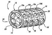
- FIG. 1illustrates one embodiment of a modular fusion cage implant 10 according to the present disclosure.
- Fusion implant 10includes a generally elongated body 12 having a first end 14 , a second end 16 and an end cap 40 ( FIGS. 3A-3C ) which is mountable to the body 12 .
- Cage 10is preferably fabricated from a suitable biocompatible rigid material such as titanium and/or alloys of titanium, stainless steel, ceramic materials or rigid polymeric materials. Moreover, it is envisioned that cage 10 is sufficient in strength to at least partially replace the supporting function of an intervertebral disc, i.e., to maintain adjacent vertebrae in desired spaced relation, during healing and fusion.
- the body 12 of cage 10includes an outer wall 15 which encloses an inner cavity 22 defined within the interior of the cage body 12 .
- Inner cavity 22accommodates bone growth substances which induce the soft cancellous bone surrounding the vertebrae to grow inwardly towards the contact surfaces of the fusion cage 10 to stabilize the cage 10 between two adjacent vertebrae 202 , 204 (See FIGS. 5 A and 5 B).
- outer wall 15can be designed in a variety of different shapes depending upon a specific purpose, e.g., oval-shaped, kidney-shaped, etc.
- the surface of outer wall 15may be coated with a variety of different materials which facilitate insertion of the cage 10 and enhance retention of the cage 10 between opposing vertebrae 202 , 204 .
- a plurality of apertures 20extend through outer wall 15 of cage body 12 and preferably promote immediate bone to bone contact between the vertebral bodies 202 , 204 and the bone inducing substances packed within the internal cavity 22 of the cage body 12 .
- Such arrangement of apertures 20is disclosed in commonly assigned U.S. Pat. Nos. 4,961,740 and 5,026,373, the contents of which are hereby incorporated by reference.
- Apertures 20are preferably substantially the same in dimension although it is envisioned that the dimensions of the apertures 20 may vary to provide for more or less bone-to-bone contact depending upon a particular purpose.
- apertures 20are oriented such that when the cage 10 is inserted between the upper and lower vertebral bone structures 202 , 204 , the apertures 20 encourage bony ingrowth through cage body 12 from the vertebral bone structures 202 , 204 .
- the body 12 of cage 10includes seam or grooves 18 which encircle the outer periphery of body 12 .
- Grooves 18segment the body 12 into discrete ring-like segments, e.g., 13 a , 13 b , 13 c and 13 d .
- the grooves 18act as cutting guides as well as measurement guides in determining the desired length of the fusion cage 10 needed. It is envisioned that the height of each ring-like segment, e.g., 13 a , and therefore, the distance between each corresponding groove 18 , may be varied depending upon a particular purpose.
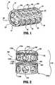
- FIG. 2One embodiment of a fusion cage 100 according to the present disclosure is illustrated in FIG. 2 and includes a plurality of ring-like segments 113 a and 113 b which mechanically engage one another in an end-to-end or stack-like manner to form elongated tube body 112 .
- Each ring segment, 113 a , 113 bincludes a plurality of apertures 120 located therethrough which are appropriately sized to promote immediate bone to bone contact between the vertebral bodies 202 , 204 ( FIG. 5A ) and the bone inducing substances as described above.
- the first end of ring-like segment 113 ae.g., end 114 a , preferably includes a mechanical interface, e.g., flange 125 , which is dimensioned to mechanically engage a corresponding annular recess or lip 129 disposed within the opposed end 116 b of ring-like segment 113 b .
- the ring segments 113 a , 113 bmay be designed with other types of mechanically engaging interfaces depending upon a particular purpose, e.g., interlocking wedges, locking pins, etc.
- groove 18is formed as a result of the union of the two ring-like segments 113 a , 113 b .
- the grooves 18may project from body 12 and include sharp edges which eliminate the need for any internal rings in the sizing device. It is envisioned that the grooves will also promote subsidence into the vertebral bodies 202 , 204 .
- End 116 a of ring segment 113 aincludes a flange 125 which is designed to engage a third ring segment (not shown) to further the length of elongate body 112 depending upon a particular purpose or, alternatively, the flange 125 may engage an end cap 40 in a manner described below with respect to FIGS. 3A-3C . It is envisioned that the end 114 b of ring segment 113 b may also include a mechanical interface (not shown) designed to engage another ring segment (not shown) or, alternatively, a second end cap 40 if needed.
- the size, number and shape (e.g., oval shape, kidney-shape, etc.) of the of ring-like segments 113 a , 113 bmay vary enabling the surgeon to quickly and easily customize each fusion cage 100 according to the pre-defined intervertebral space “I” between a patient's opposing vertebrae 202 , 204 .
- ring segment 113 amay also be designed in a C-shaped or split-ring configuration to facilitate engagement with ring segment 113 b . More particularly, ring segment 113 a includes a pair of opposing edges 131 a , 131 b , respectively, which define an open slit 130 in the outer wall 115 thereof which enables a surgeon to radially compress ring segment 113 a inwardly enabling facile mechanical engagement of flange 125 with the lip 129 of ring segment 113 b .
- flange 125 and lip 129are properly aligned or seated, i.e., engaged, the surgeon simply reduces inward compressive pressure to interlock the two ring segments 113 a and 113 b together. The surgeon simply compresses ring 113 a again to disengage the two ring segments 113 a , 113 b if needed.
- a surgeoncan quickly and easily change the size and shape of the cage 100 as needed to ensure proper positioning within the intervertebral space “I” between opposing vertebrae 202 , 204 .
- cage 10 , 100can be dimensioned such that cage 10 , 100 is generally symmetrical, i.e., end-to-end symmetry, which permits insertion of the cage 10 from either end 14 , 16 .
- FIGS. 3A-4Cdisclose various configurations of the end cap 40 which mounts to the elongated body 12 , 112 .
- the end cap 40can be configured to mount to either or both ends 14 , 16 depending upon a particular purpose.
- the end 14 of the body 12may include an annular recess 23 which is configured to receive a plurality of diametrically opposing, semi-resilient detents or locking pins 48 which protrude from an inner diameter 44 of the end cap 40 of FIG. 3 A.
- a plurality of apertures 46extend through end cap 40 thereby permitting direct growth or passage of bone or bone growth inducing substances through apertures 46 .
- FIG. 3Bshows an alternate end cap 140 which includes an outer peripheral portion 142 , an inner diameter 144 and a plurality of apertures 146 disposed therethrough.
- the inner diameter 144generally tapers in an inward fashion, i.e., from an adjoining edge 145 which has a first diameter to a leading edge 147 which has a reduced diameter.
- the diameter of adjoining edge 145is dimensioned slightly larger than the inner diameter 144 of elongated body 12 and the diameter of leading edge 147 is dimensioned slightly smaller than the inner diameter 144 .
- this diametrically-tapered configuration of the inner diameter 144allows the surgeon to quickly and easily wedge end cap 140 within the end 14 of the fusion cage 10 in a secure, friction-fit manner.
- FIG. 3Cshows another embodiment of an end cap 240 which includes an outer peripheral portion 242 , an inner diameter 244 and a single aperture 246 disposed therethrough.
- the end cap 240is generally C-shaped and includes two opposing ends 247 a and 247 b which define a slit 249 therebetween giving the end cap 240 an overall split-ring appearance.
- the inner diameter 244 of end cap 240also includes a flange 243 disposed about the outer periphery thereof.
- Flange 243is dimensioned to “snap” into and seat within annular recess 23 of body 12 (See FIG. 1 ) after end cap 240 is inserted within body 12 .
- slit 249is communicated through both the outer peripheral portion 242 and the inner diameter 244 such that the entire end cap 240 has some degree of radial resiliency. As can be appreciated, this enables the surgeon to quickly and easily mount the end cap 240 onto body 12 upon the application and subsequent release of inward, radial pressure.
- bone or bone growth inducing substancescan easily infiltrate cage 10 , 100 through aperture 246 to promote fusion between the cage 10 and the vertebral bodies 202 , 204 .
- FIGS. 6A and 6Bshow yet another embodiment of an end cap 640 according to the present disclosure which includes an outer portion 642 having an inner periphery 643 which defines a central aperture 646 therethrough.
- a pair of opposing, arcuately-shaped retaining sleeves 644 a and 644 bextend concentrically and distally along axis “A” with respect to inner periphery 643 and each include an outer rim-like flange 651 a and 651 b , respectively, at the distal end thereof.
- arcuate sleeves 644 a and 644 bare semi-resilient and are dimensioned to mechanically engage the inner annular recess 23 of body 12 .
- sleeves 644 a and 644 bradially compress inwardly towards axis “A” when end cap 640 is inserted within body 12 and outer flanges 651 a and 651 b “snap” into annular recess 23 to secure end cap 640 to cage 10 .
- the face of the end cap 640also includes a plurality of spike-like detents 652 which are designed to anchor the cage 12 (once assembled with end cap 640 ) to the underside of the opposing vertebral bodies 202 , 204 . It is envisioned that these detents can be mounted or integrally incorporated with any one of the above-mentioned end cap configurations, e.g., 40 , 140 , 240 , 340 , 44 , and 540 .
- FIG. 4Ashows one arrangement of detents 352 which are integrally associated with a donut-like end cap 340 .
- the detents 352are arranged in an array-like fashion about a centrally disposed aperture 346 defined through end cap 340 .
- detents 352project from face 342 to engage the underside of the vertebral bodies 202 , 204 . It is envisioned that the detents 352 may project from face 342 at varying angles relative to the face 342 which may facilitate insertion and/or improve subsidence of the cage 10 into the vertebral bodies 202 , 204 .
- FIG. 4Bshows another embodiment of an end cap 440 having a plurality of apertures 446 disposed through the face 450 thereof.
- a plurality of spike-like detents 452are arranged radially about the periphery of the face 450 proximate outer rim 442 .
- the detents 352 , 452may vary in size and dimension depending upon a particular purpose or to achieve a desired result.
- FIG. 4Cshows yet another embodiment of a C-Shaped end cap 540 having two opposing edges 541 a and 541 b which define a slit 549 therebetween.
- the end cap 540also includes a face 550 having outer and inner peripheries 542 and 547 , respectively.
- the inner periphery 547defines a central aperture 546 therethrough which provides a passageway for the bone growth inducing substances which are used to promote fusion as mentioned above.
- a plurality of arcuately-shaped wedges 552having a generally triangular cross section extend outwardly from the proximal face 550 and serve to anchor the cage 10 (once assembled with the end cap 540 ) to the underside of the vertebral bodies 202 , 204 . It is envisioned that the slit 549 allows the end cap 540 to contract radially inwardly to facilitate mounting the end cap to the cage 10 as described above with respect to FIG. 3 C.
- the present disclosurealso relates to a method of inserting a the fusion cage 10 into an intervertebral space “I” defined between vertebrae 202 , 204 .
- a method of inserting a the fusion cage 10 into an intervertebral space “I” defined between vertebrae 202 , 204Initially, one lateral side of an intervertebral space “I” between the two vertebral bodies 202 , 204 is accessed utilizing appropriate retractors (not shown) to expose the vertebral surface. Thereafter, a retractor is inserted within the intervertebral space “I” between vertebral bodies 202 , 204 for distracting the vertebral bodies 202 , 204 to a desired predetermined distance. A partial or full discectomy may be performed.
- the modular fusion cage 10is then assembled and sized to determine the appropriate number of ring segments, e.g., 13 a , 13 b , 13 c and 13 d , needed to fit in the intervertebral space “I” and maintain the adjacent vertebral bodies in the predetermined space during the fusion process.
- no internal ringsare required because of the sharp edges or grooves 18 produced in the sizing device which allow subsidence into the vertebral bodies 202 , 204 .
- the segmented design of the cage 10eliminates the need for cutting tools and measuring guides.
- the fusion cage 10is then packed with bone growth inducing substances as in conventional in the art and one of the above-identified end caps is then mounted to the cage 10 in one of the above-identified manners.
- the cage 10 and end cap assemblyis then mounted on an insertion instrument (not shown) and driven between the vertebral bodies 202 , 204 .
- the spike-like detents 352 , 452 or 552promote subsidence into the vertebral bodies 202 , 204 .
- Cage 10is then released from the mounting instrument which is subsequently removed from the disc area. It is envisioned that a second end cap may be mounted to the distal end of cage 10 to retain the bone growth substances within cage 10 .
- a second lateral side of the intervertebral space “I”may be accessed and the above-described process is repeated to insert a second cage 10 in side-by-side relation as shown in FIG. 5 B.
- the cages 10 , 10are arranged such that the cages 10 , 10 reside in adjacent side-by-side relation.
- the fusion cages 10 , 10form struts across the intervertebral space “I” to maintain the vertebrae 202 , 204 in appropriate spaced relation during the fusion process.
- the vertebral tissuecommunicates through apertures 20 within cages 10 , 10 to form a solid fusion.
Landscapes
- Health & Medical Sciences (AREA)
- Engineering & Computer Science (AREA)
- Biomedical Technology (AREA)
- Neurology (AREA)
- Orthopedic Medicine & Surgery (AREA)
- Cardiology (AREA)
- Oral & Maxillofacial Surgery (AREA)
- Transplantation (AREA)
- Heart & Thoracic Surgery (AREA)
- Vascular Medicine (AREA)
- Life Sciences & Earth Sciences (AREA)
- Animal Behavior & Ethology (AREA)
- General Health & Medical Sciences (AREA)
- Public Health (AREA)
- Veterinary Medicine (AREA)
- Prostheses (AREA)
Abstract
Description
The present disclosure generally relates to a surgical apparatus for fusing adjacent bone structures, and, more particularly, to a segmented and/or modular apparatus and method for fusing adjacent vertebrae.
The fusion of adjacent bone structures is commonly performed to provide for long-term replacement to compensate for vertebral subluxation typically caused by severe trauma to the spine, degenerative or deteriorated bone disorders, e.g., osteoporosis, abnormal curvature of the spine (scoliosis or kyphosis) and/or weak or unstable spine conditions typically caused by infections or tumors. In addition, an intervertebral disc, which is a ligamentous cushion disposed between adjacent vertebrae, may also undergo deterioration or degeneration as a result of injury, disease, tumor or other disorders. The disk shrinks or flattens leading to mechanical instability and painful disc translocations, commonly referred to as a “slipped disc” or “herniated disc”.
Conventional procedures for disc surgery include partial or total excision of the injured disc portion, e.g., discectomy, and replacement of the excised disc with biologically acceptable plugs or bone wedges. The plugs are driven between adjacent vertebrae to maintain normal intervertebral spacing and to achieve, over a period of time, bony ingrowth or “fusion” with the plug and opposed vertebrae.
Alternatively, a metallic fusion cage may be inserted within a tapped bore or channel formed in the intervertebral space thereby stabilizing the vertebrae and maintaining a pre-defined intervertebral space. A pair of fusion cages may also be implanted within the intervertebral space. After a period of time, the soft cancellous bone of the surrounding vertebral bone structures infiltrates the cage through a series of apertures in the cage wall and unites with bone growth inducing substances disposed within an internal cavity of the cage wall to eventually form a solid fusion of the adjacent vertebrae.
The present disclosure relates to a fusion implant apparatus for facilitating fusion of adjacent bone structures. The fusion apparatus includes a modular implant member for positioning between adjacent opposed bone structures and having a plurality of ring-like segments which engage one another in an end-to-end or stack-like manner. Each ring-like segment includes an outer wall which defines an internal cavity for the reception of bone growth inducing substances and includes a plurality of apertures which extend through the outer wall of the ring-like segments in communication with the internal cavity to permit fusion of vertebral bone tissue. Preferably, at least one ring-like segment includes first and second mechanical interfaces, the first mechanical interface being dimensioned to engage a corresponding mechanical interface disposed on another ring-like segment and the second mechanical interface being dimensioned to mechanically engage an end cap. At least one ring segment preferably incorporates a C-shaped or split ring configuration with semi-resilient characteristics to facilitate engagement with another ring-like segment.
The end cap preferably includes a plurality of detents or spike-like protrusions which project outwardly therefrom and which are designed to anchor the fusion cage to the underside of the vertebral bodies. The end cap may also include one or more flanges, retaining sleeves, locking pins, or other mechanically interfacing mechanism for securing the end cap to the body of the implant member. In one embodiment, the end cap has a C-shaped or split ring configuration to facilitate mounting the end cap to the implant member.
Referring now to the drawings in which like reference numerals identify similar or identical elements throughout the several views,FIG. 1 illustrates one embodiment of a modularfusion cage implant 10 according to the present disclosure.Fusion implant 10 includes a generallyelongated body 12 having afirst end 14, asecond end 16 and an end cap40 (FIGS. 3A-3C ) which is mountable to thebody 12.
Cage10 is preferably fabricated from a suitable biocompatible rigid material such as titanium and/or alloys of titanium, stainless steel, ceramic materials or rigid polymeric materials. Moreover, it is envisioned thatcage 10 is sufficient in strength to at least partially replace the supporting function of an intervertebral disc, i.e., to maintain adjacent vertebrae in desired spaced relation, during healing and fusion.
As best shown inFIG. 1 , thebody 12 ofcage 10 includes anouter wall 15 which encloses aninner cavity 22 defined within the interior of thecage body 12.Inner cavity 22 accommodates bone growth substances which induce the soft cancellous bone surrounding the vertebrae to grow inwardly towards the contact surfaces of thefusion cage 10 to stabilize thecage 10 between twoadjacent vertebrae 202,204 (See FIGS.5A and5B). It is envisioned thatouter wall 15 can be designed in a variety of different shapes depending upon a specific purpose, e.g., oval-shaped, kidney-shaped, etc. It is also envisioned that the surface ofouter wall 15 may be coated with a variety of different materials which facilitate insertion of thecage 10 and enhance retention of thecage 10 betweenopposing vertebrae
As best shown inFIG. 1 , a plurality ofapertures 20 extend throughouter wall 15 ofcage body 12 and preferably promote immediate bone to bone contact between thevertebral bodies internal cavity 22 of thecage body 12. Such arrangement ofapertures 20 is disclosed in commonly assigned U.S. Pat. Nos. 4,961,740 and 5,026,373, the contents of which are hereby incorporated by reference.Apertures 20 are preferably substantially the same in dimension although it is envisioned that the dimensions of theapertures 20 may vary to provide for more or less bone-to-bone contact depending upon a particular purpose.
Preferably,apertures 20 are oriented such that when thecage 10 is inserted between the upper and lowervertebral bone structures apertures 20 encourage bony ingrowth throughcage body 12 from thevertebral bone structures
As shown inFIG. 1 , thebody 12 ofcage 10 includes seam orgrooves 18 which encircle the outer periphery ofbody 12.Grooves 18 segment thebody 12 into discrete ring-like segments, e.g.,13a,13b,13cand13d. Preferably, thegrooves 18 act as cutting guides as well as measurement guides in determining the desired length of thefusion cage 10 needed. It is envisioned that the height of each ring-like segment, e.g.,13a, and therefore, the distance between eachcorresponding groove 18, may be varied depending upon a particular purpose.
One embodiment of afusion cage 100 according to the present disclosure is illustrated in FIG.2 and includes a plurality of ring-like segments 113aand113bwhich mechanically engage one another in an end-to-end or stack-like manner to formelongated tube body 112. Each ring segment,113a,113b, includes a plurality ofapertures 120 located therethrough which are appropriately sized to promote immediate bone to bone contact between thevertebral bodies 202,204 (FIG. 5A ) and the bone inducing substances as described above. The first end of ring-like segment 113a, e.g., end114a, preferably includes a mechanical interface, e.g.,flange 125, which is dimensioned to mechanically engage a corresponding annular recess orlip 129 disposed within the opposed end116bof ring-like segment113b. Thering segments 113a,113bmay be designed with other types of mechanically engaging interfaces depending upon a particular purpose, e.g., interlocking wedges, locking pins, etc.
As can be appreciated, groove18 is formed as a result of the union of the two ring-like segments 113a,113b. Thegrooves 18 may project frombody 12 and include sharp edges which eliminate the need for any internal rings in the sizing device. It is envisioned that the grooves will also promote subsidence into thevertebral bodies
End116aofring segment 113aincludes aflange 125 which is designed to engage a third ring segment (not shown) to further the length ofelongate body 112 depending upon a particular purpose or, alternatively, theflange 125 may engage anend cap 40 in a manner described below with respect toFIGS. 3A-3C . It is envisioned that the end114bof ring segment113bmay also include a mechanical interface (not shown) designed to engage another ring segment (not shown) or, alternatively, asecond end cap 40 if needed.
As can be appreciated by the present disclosure, no screws are required to assemble the various components of thecage 100, i.e., thering segments 113a,113b, etc. and the end caps40,140,240,340,440 and540 as described below prior to and/or during implantation. Moreover, the size, number and shape (e.g., oval shape, kidney-shape, etc.) of the of ring-like segments 113a,113bmay vary enabling the surgeon to quickly and easily customize eachfusion cage 100 according to the pre-defined intervertebral space “I” between a patient's opposingvertebrae
As best shown inFIG. 2 ,ring segment 113amay also be designed in a C-shaped or split-ring configuration to facilitate engagement with ring segment113b. More particularly,ring segment 113aincludes a pair of opposingedges 131a,131b, respectively, which define anopen slit 130 in theouter wall 115 thereof which enables a surgeon to radiallycompress ring segment 113ainwardly enabling facile mechanical engagement offlange 125 with thelip 129 of ring segment113b. Onceflange 125 andlip 129 are properly aligned or seated, i.e., engaged, the surgeon simply reduces inward compressive pressure to interlock the tworing segments 113aand113btogether. The surgeon simply compressesring 113aagain to disengage the tworing segments 113a,113bif needed. As can be appreciated, a surgeon can quickly and easily change the size and shape of thecage 100 as needed to ensure proper positioning within the intervertebral space “I” between opposingvertebrae
As stated above, it is also envisioned thatcage cage cage 10 from eitherend
Theinner diameter 244 ofend cap 240 also includes aflange 243 disposed about the outer periphery thereof.Flange 243 is dimensioned to “snap” into and seat withinannular recess 23 of body12 (SeeFIG. 1 ) afterend cap 240 is inserted withinbody 12. Preferably, slit249 is communicated through both the outerperipheral portion 242 and theinner diameter 244 such that theentire end cap 240 has some degree of radial resiliency. As can be appreciated, this enables the surgeon to quickly and easily mount theend cap 240 ontobody 12 upon the application and subsequent release of inward, radial pressure. After theend cap 240 is mounted tobody 12, bone or bone growth inducing substances can easily infiltratecage aperture 246 to promote fusion between thecage 10 and thevertebral bodies
As best seen inFIGS. 6A and 6B , the face of theend cap 640 also includes a plurality of spike-like detents 652 which are designed to anchor the cage12 (once assembled with end cap640) to the underside of the opposingvertebral bodies
Moreover, various other configurations of detents are also envisioned. For example,FIG. 4A shows one arrangement ofdetents 352 which are integrally associated with a donut-like end cap 340. In this particular embodiment, thedetents 352 are arranged in an array-like fashion about a centrally disposedaperture 346 defined throughend cap 340. Preferably,detents 352 project fromface 342 to engage the underside of thevertebral bodies detents 352 may project fromface 342 at varying angles relative to theface 342 which may facilitate insertion and/or improve subsidence of thecage 10 into thevertebral bodies
As can be appreciated, all of the above end cap embodiments snap into or mount to thecage 10 easily and readily without requiring screws or other retention devices.
The present disclosure also relates to a method of inserting a thefusion cage 10 into an intervertebral space “I” defined betweenvertebrae vertebral bodies vertebral bodies vertebral bodies
Themodular fusion cage 10 is then assembled and sized to determine the appropriate number of ring segments, e.g.,13a,13b,13cand13d, needed to fit in the intervertebral space “I” and maintain the adjacent vertebral bodies in the predetermined space during the fusion process. As can be appreciated, no internal rings are required because of the sharp edges orgrooves 18 produced in the sizing device which allow subsidence into thevertebral bodies cage 10 eliminates the need for cutting tools and measuring guides.
Thefusion cage 10 is then packed with bone growth inducing substances as in conventional in the art and one of the above-identified end caps is then mounted to thecage 10 in one of the above-identified manners. Thecage 10 and end cap assembly is then mounted on an insertion instrument (not shown) and driven between thevertebral bodies like detents vertebral bodies
A second lateral side of the intervertebral space “I” may be accessed and the above-described process is repeated to insert asecond cage 10 in side-by-side relation as shown in FIG.5B. Preferably, thecages cages
Once implanted, thefusion cages vertebrae apertures 20 withincages
From the foregoing and with reference to the various figure drawings, those skilled in the art will appreciate that certain modifications can also be made to the present disclosure without departing from the scope of the same. While the above description contains many specifics, these specifics should not be construed as limitations on the scope of the disclosure, but merely as exemplifications of preferred embodiments thereof. Those skilled in the art will envision other modifications within the scope and spirit of the claims appended hereto.
Claims (29)
1. A fusion implant apparatus for facilitating fusion of bone structures, comprising:
an implant member for positioning between opposed bone structures, the implant member having a segmentable portion having an outer wall defining an internal cavity for reception of bone growth inducing substances, the outer wall having at least one groove which extends substantially continuously about the outer wall forming a juncture between discrete ring-like segments on either side of the groove, wherein the outer wall of the implant member does not outwardly protrude between the adjacent ring-like segments, each ring-like segment including a plurality of apertures extending therethrough in communication with the internal cavity to permit fusion of the vertebral bone tissue, wherein none of the apertures and none of the at least one groove intersect each other; and
the first end and/or the second end being dimensioned to engage an end cap.
2. The fusion implant apparatus ofclaim 1 , wherein the groove acts as a cutting guide to determine the desired length of the fusion implant.
3. The fusion implant apparatus ofclaim 1 , wherein the groove acts as a measurement guide to determine the desired length of the fusion implant.
4. The fusion implant apparatus ofclaim 1 , wherein the outer wall includes a plurality of grooves that segment the body into discrete ring-like segments and do not intersect the apertures.
5. The fusion implant apparatus ofclaim 4 , wherein the height of at least two of the ring-like segments are varied.
6. The fusion implant apparatus ofclaim 4 , wherein the grooves are oriented parallel to each other.
7. The fusion implant apparatus ofclaim 1 , further including an end cap which is mountable to the first or second end of the implant member.
8. The fusion implant apparatus ofclaim 4 , wherein the end cap includes a face having at least one aperture disposed therethrough which communicates with the internal cavity to permit fusion of vertebral bone tissue.
9. The fusion implant apparatus ofclaim 4 , wherein the face of the end cap includes a plurality of apertures disposed therethrough which are arranged in an array-like manner about the face.
10. The fusion implant apparatus ofclaim 7 , wherein the end cap includes a face having a plurality of detents which extend outwardly therefrom, which serve to anchor the fusion apparatus to the bone structure.
11. The fusion implant apparatus ofclaim 10 , wherein the detents are arranged radially about the face of the end cap.
12. The fusion implant apparatus ofclaim 10 , wherein the detents are a spike-like configuration.
13. The fusion implant apparatus ofclaim 10 , wherein the detents are arcuately-shaped and have a triangular cross section.
14. The fusion implant apparatus ofclaim 7 , wherein the end cap includes at least one mechanical interface which engages the corresponding first or second end of the implant member.
15. The fusion implant apparatus ofclaim 14 , wherein the mechanical interface of the end cap includes a plurality of locking pins which engage the first or second end of the implant member.
16. The fusion implant apparatus ofclaim 14 , wherein the mechanical interface of the end cap includes a diametrically tapered inner diameter, which is dimensioned for friction-fit engagement within the first or second end of the implant member.
17. The fusion implant apparatus ofclaim 14 , wherein the mechanical interface of the end cap is generally C-shaped and includes:
two opposing ends which define a slit therebetween; and
a flange which is dimensioned to engage an annular recess disposed within the first or second end of the implant member.
18. The fusion implant apparatus according toclaim 14 , wherein the mechanical interface of the end cap includes two opposing arcuately-shaped retaining sleeves which extend concentrically within an inner periphery of the end cap and are dimensioned to engage an annular recess within the first or second end of the implant member.
19. The fusion implant apparatus ofclaim 18 , wherein the arcuately-shaped retaining sleeves include an outer rim which is dimensioned to engage the annular recess disposed within the first or second end of the implant member.
20. A method for fusing vertebrae, comprising the steps of;
providing an implant member for positioning between opposed bone structures, the implant member having a first end and a second end dimensioned to engage an end cap, and a segmentable portion having an outer wall defining an internal cavity for reception of bone growth inducing substances, the outer wall having at least one groove which extends substantially continuously about the outer wall to define a plurality of discrete ring-like segments, each ring-like segment including a plurality of apertures extending therethrough in communication with the internal cavity to permit fusion of the vertebral bone tissue, wherein none of the apertures and none of the at least one groove intersect each other;
accessing the vertebral space defined between adjacent vertebral bodies;
determining the desired implant member length for insertion into the space between the adjacent vertebral bodies by using one of the grooves as a cutting and/or measurement guide;
sizing the implant member; and
advancing the implant member within the vertebral space between the adjacent vertebral bodies.
21. The method for fusing vertebrae ofclaim 20 , further including packing the implant member with bone growth inducing substances.
22. The method of fusing vertebrae ofclaim 20 , further including mounting an end cap to the first or second end of the implant member.
23. A fusion implant apparatus for facilitating fusion of bone structures, comprising:
an implant member for positioning between opposed bone structures, the implant member having a first end and a second end, and a segmentable portion having an outer wall defining an internal cavity for reception of bone growth inducing substances, the outer wall having a plurality of grooves which extend substantially continuously about the outer wall to define a plurality of discrete ring-like segments, each ring-like segment including a plurality of apertures extending therethrough in communication with the internal cavity to permit fusion of the vertebral bone tissue, wherein none of the apertures intersect the grooves; and
the first end and/or the second end being dimensioned to engage an end cap.
24. A fusion implant apparatus ofclaim 23 , wherein the grooves act as cutting guides to determine the desired length of the fusion implant.
25. A fusion implant apparatus ofclaim 23 , wherein the grooves act as measurement guides to determine the desired length of the fusion implant.
26. A fusion implant apparatus ofclaim 23 , wherein the height of at least two of the ring-like segments are varied.
27. A fusion implant apparatus ofclaim 23 , wherein the grooves are oriented parallel to each other.
28. A fusion implant apparatus ofclaim 23 , further including an end cap which is mountable to the first or second end of the implant member.
29. A fusion implant apparatus ofclaim 28 , wherein the end cap includes a phase having at least one aperture disposed therethrough which communicates with the internal cavity to permit fusion of the vertebral bone tissue.
Priority Applications (6)
| Application Number | Priority Date | Filing Date | Title |
|---|---|---|---|
| US09/815,504US6899734B2 (en) | 2001-03-23 | 2001-03-23 | Modular implant for fusing adjacent bone structure |
| EP09157005AEP2108340B1 (en) | 2001-03-23 | 2002-01-24 | Spinal Fusion Implant |
| EP02726560AEP1370185A1 (en) | 2001-03-23 | 2002-01-24 | Modular implant for fusing adjacent bone structure |
| AT09157005TATE525041T1 (en) | 2001-03-23 | 2002-01-24 | SPINAL FUSION IMPLANT |
| PCT/US2002/002024WO2002076316A1 (en) | 2001-03-23 | 2002-01-24 | Modular implant for fusing adjacent bone structure |
| US11/112,476US7303584B2 (en) | 2001-03-23 | 2005-04-22 | Modular implant for fusing adjacent bone structure |
Applications Claiming Priority (1)
| Application Number | Priority Date | Filing Date | Title |
|---|---|---|---|
| US09/815,504US6899734B2 (en) | 2001-03-23 | 2001-03-23 | Modular implant for fusing adjacent bone structure |
Related Child Applications (1)
| Application Number | Title | Priority Date | Filing Date |
|---|---|---|---|
| US11/112,476ContinuationUS7303584B2 (en) | 2001-03-23 | 2005-04-22 | Modular implant for fusing adjacent bone structure |
Publications (2)
| Publication Number | Publication Date |
|---|---|
| US20020138142A1 US20020138142A1 (en) | 2002-09-26 |
| US6899734B2true US6899734B2 (en) | 2005-05-31 |
Family
ID=25217996
Family Applications (2)
| Application Number | Title | Priority Date | Filing Date |
|---|---|---|---|
| US09/815,504Expired - LifetimeUS6899734B2 (en) | 2001-03-23 | 2001-03-23 | Modular implant for fusing adjacent bone structure |
| US11/112,476Expired - Fee RelatedUS7303584B2 (en) | 2001-03-23 | 2005-04-22 | Modular implant for fusing adjacent bone structure |
Family Applications After (1)
| Application Number | Title | Priority Date | Filing Date |
|---|---|---|---|
| US11/112,476Expired - Fee RelatedUS7303584B2 (en) | 2001-03-23 | 2005-04-22 | Modular implant for fusing adjacent bone structure |
Country Status (4)
| Country | Link |
|---|---|
| US (2) | US6899734B2 (en) |
| EP (2) | EP1370185A1 (en) |
| AT (1) | ATE525041T1 (en) |
| WO (1) | WO2002076316A1 (en) |
Cited By (66)
| Publication number | Priority date | Publication date | Assignee | Title |
|---|---|---|---|---|
| US20040158321A1 (en)* | 2003-02-12 | 2004-08-12 | Cardiac Dimensions, Inc. | Method of implanting a mitral valve therapy device |
| US20040193260A1 (en)* | 2001-12-05 | 2004-09-30 | Alferness Clifton A. | Anchor and pull mitral valve device and method |
| US20040220657A1 (en)* | 2003-05-02 | 2004-11-04 | Cardiac Dimensions, Inc., A Washington Corporation | Tissue shaping device with conformable anchors |
| US20040249452A1 (en)* | 2001-11-01 | 2004-12-09 | Adams John M. | Focused compression mitral valve device and method |
| US20050004671A1 (en)* | 2003-07-01 | 2005-01-06 | Thomas Ross | Spinal spacer assembly |
| US20050010240A1 (en)* | 2003-06-05 | 2005-01-13 | Cardiac Dimensions Inc., A Washington Corporation | Device and method for modifying the shape of a body organ |
| US20050021121A1 (en)* | 2001-11-01 | 2005-01-27 | Cardiac Dimensions, Inc., A Delaware Corporation | Adjustable height focal tissue deflector |
| US20050027351A1 (en)* | 2001-05-14 | 2005-02-03 | Cardiac Dimensions, Inc. A Washington Corporation | Mitral valve regurgitation treatment device and method |
| US20050096666A1 (en)* | 2002-12-05 | 2005-05-05 | Gordon Lucas S. | Percutaneous mitral valve annuloplasty delivery system |
| US20050119673A1 (en)* | 2002-12-05 | 2005-06-02 | Gordon Lucas S. | Percutaneous mitral valve annuloplasty device delivery method |
| US20050137685A1 (en)* | 2003-12-19 | 2005-06-23 | Cardiac Dimensions, Inc., A Washington Corporation | Reduced length tissue shaping device |
| US20050137451A1 (en)* | 2003-12-19 | 2005-06-23 | Cardiac Dimensions, Inc. A Washington Corporation | Tissue shaping device with integral connector and crimp |
| US20050137450A1 (en)* | 2003-12-19 | 2005-06-23 | Cardiac Dimensions, Inc., A Washington Corporation | Tapered connector for tissue shaping device |
| US20050149179A1 (en)* | 2002-05-08 | 2005-07-07 | Mathis Mark L. | Body lumen device anchor, device and assembly |
| US20050209690A1 (en)* | 2002-01-30 | 2005-09-22 | Mathis Mark L | Body lumen shaping device with cardiac leads |
| US20050216077A1 (en)* | 2002-01-30 | 2005-09-29 | Mathis Mark L | Fixed length anchor and pull mitral valve device and method |
| US20050261704A1 (en)* | 2001-05-14 | 2005-11-24 | Mathis Mark L | Mitral valve therapy assembly and method |
| US20050272969A1 (en)* | 2001-12-05 | 2005-12-08 | Alferness Clifton A | Device and method for modifying the shape of a body organ |
| US20060020335A1 (en)* | 2002-12-26 | 2006-01-26 | Leonard Kowalsky | System and method to effect the mitral valve annulus of a heart |
| US20060111716A1 (en)* | 2003-03-21 | 2006-05-25 | Andre Schlienger | Intramedullary nail |
| US20060161169A1 (en)* | 2003-05-02 | 2006-07-20 | Cardiac Dimensions, Inc., A Delaware Corporation | Device and method for modifying the shape of a body organ |
| US20060271174A1 (en)* | 2003-12-19 | 2006-11-30 | Gregory Nieminen | Mitral Valve Annuloplasty Device with Wide Anchor |
| US20060276891A1 (en)* | 2003-12-19 | 2006-12-07 | Gregory Nieminen | Mitral Valve Annuloplasty Device with Twisted Anchor |
| US20070028710A1 (en)* | 2003-05-14 | 2007-02-08 | Kilian Kraus | Height-adjustable implant to be inserted between vertebral bodies and corresponding handling tool |
| US20070055293A1 (en)* | 2001-12-05 | 2007-03-08 | Alferness Clifton A | Device and method for modifying the shape of a body organ |
| US20070073395A1 (en)* | 2003-04-11 | 2007-03-29 | Daniel Baumgartner | Anchoring means for intervertebral implants |
| US20070129805A1 (en)* | 2005-12-01 | 2007-06-07 | Braddock Danny H Jr | End device for a vertebral implant |
| US20070135912A1 (en)* | 2003-02-03 | 2007-06-14 | Mathis Mark L | Mitral valve device using conditioned shape memory alloy |
| US20070239270A1 (en)* | 2006-04-11 | 2007-10-11 | Mathis Mark L | Mitral Valve Annuloplasty Device with Vena Cava Anchor |
| US20070255416A1 (en)* | 2006-05-01 | 2007-11-01 | Sdgi Holdings, Inc. | Intervertebral implants with covered inner chamber and methods of use |
| US20070255414A1 (en)* | 2006-05-01 | 2007-11-01 | Sdgi Holdings, Inc. | Intervertebral implants with one or more covers and methods of use |
| US20070270844A1 (en)* | 2004-11-03 | 2007-11-22 | The Regents Of The University Of Michigan | Biodegradable implant for intertransverse process fusion |
| US20080015407A1 (en)* | 2003-05-02 | 2008-01-17 | Mathis Mark L | Device and Method for Modifying the Shape of a Body Organ |
| US20080021555A1 (en)* | 2006-07-19 | 2008-01-24 | John White | Expandable vertebral body implants and methods of use |
| US20080027436A1 (en)* | 2006-07-14 | 2008-01-31 | John Cournoyer | Rod to Rod Connectors and Methods of Adjusting The Length Of A Spinal Rod Construct |
| US20080058939A1 (en)* | 2006-08-25 | 2008-03-06 | Warsaw Orthopedic, Inc. | Revision Spacer |
| US20080077248A1 (en)* | 2006-09-22 | 2008-03-27 | Alphatec Spine, Inc. | Vertebral body replacement |
| US20080103602A1 (en)* | 2002-03-21 | 2008-05-01 | Berry Bret M | Vertebral body and disc space replacement devices |
| US20090062917A1 (en)* | 2007-08-27 | 2009-03-05 | Foley Kevin T | Spinal interbody replacement devices |
| US7544208B1 (en) | 2004-05-03 | 2009-06-09 | Theken Spine, Llc | Adjustable corpectomy apparatus |
| US20090157190A1 (en)* | 2007-12-13 | 2009-06-18 | Howmedica Inc. | Osteotomy spacer |
| US20090164017A1 (en)* | 2007-12-19 | 2009-06-25 | Robert Sommerich | Expandable Corpectomy Spinal Fusion Cage |
| US20090164018A1 (en)* | 2007-12-19 | 2009-06-25 | Robert Sommerich | Instruments For Expandable Corpectomy Spinal Fusion Cage |
| US20100280616A1 (en)* | 2009-04-29 | 2010-11-04 | William Frasier | Minimally invasive corpectomy cage and instrument |
| US7909870B2 (en) | 2003-12-11 | 2011-03-22 | Tpl - Kilian Kraus | Height-adjustable spinal implant and operating instrument for the implant |
| US7918876B2 (en) | 2003-03-24 | 2011-04-05 | Theken Spine, Llc | Spinal implant adjustment device |
| US8006594B2 (en) | 2008-08-11 | 2011-08-30 | Cardiac Dimensions, Inc. | Catheter cutting tool |
| US8454694B2 (en) | 2011-03-03 | 2013-06-04 | Warsaw Orthopedic, Inc. | Interbody device and plate for spinal stabilization and instruments for positioning same |
| US8852280B2 (en) | 2007-09-27 | 2014-10-07 | Warsaw Orthopedic, Inc. | Intervertebral implant |
| US8956415B2 (en) | 2010-08-15 | 2015-02-17 | Warsaw Orthopedic, Inc. | Vertebral implant |
| US9095444B2 (en) | 2009-07-24 | 2015-08-04 | Warsaw Orthopedic, Inc. | Implant with an interference fit fastener |
| US9216096B2 (en) | 2010-03-16 | 2015-12-22 | Pinnacle Spine Group, Llc | Intervertebral implants and related tools |
| US9380932B1 (en) | 2011-11-02 | 2016-07-05 | Pinnacle Spine Group, Llc | Retractor devices for minimally invasive access to the spine |
| US9700425B1 (en) | 2011-03-20 | 2017-07-11 | Nuvasive, Inc. | Vertebral body replacement and insertion methods |
| US9844446B2 (en) | 2016-05-05 | 2017-12-19 | Globus Medical, Inc. | Expandable vertebral implant |
| US20180071107A1 (en)* | 2016-09-14 | 2018-03-15 | Globus Medical, Inc . | Center lordotic mesh cage |
| US20180098861A1 (en)* | 2016-09-14 | 2018-04-12 | Globus Medical, Inc. | Center lordotic mesh cage |
| US10070970B2 (en) | 2013-03-14 | 2018-09-11 | Pinnacle Spine Group, Llc | Interbody implants and graft delivery systems |
| US10390953B2 (en) | 2017-03-08 | 2019-08-27 | Cardiac Dimensions Pty. Ltd. | Methods and devices for reducing paravalvular leakage |
| US10842651B2 (en) | 2016-06-10 | 2020-11-24 | Globus Medical, Inc. | Vertebral implants and attachment assemblies |
| US11033257B2 (en) | 2005-01-20 | 2021-06-15 | Cardiac Dimensions Pty. Ltd. | Tissue shaping device |
| US11285005B2 (en) | 2006-07-17 | 2022-03-29 | Cardiac Dimensions Pty. Ltd. | Mitral valve annuloplasty device with twisted anchor |
| US11596526B2 (en) | 2016-09-14 | 2023-03-07 | Globus Medical Inc. | Systems and methods for expandable corpectomy spacer implantation |
| US11596771B2 (en) | 2020-12-14 | 2023-03-07 | Cardiac Dimensions Pty. Ltd. | Modular pre-loaded medical implants and delivery systems |
| US11890320B2 (en) | 2015-04-20 | 2024-02-06 | The Board Of Regents Of The University Of Texas System | CLEC11A is a bone growth agent |
| US12161563B2 (en) | 2016-09-14 | 2024-12-10 | Globus Medical, Inc. | Systems and methods for expandable corpectomy spacer implantation |
Families Citing this family (53)
| Publication number | Priority date | Publication date | Assignee | Title |
|---|---|---|---|---|
| US20020169507A1 (en)* | 2000-12-14 | 2002-11-14 | David Malone | Interbody spine fusion cage |
| DE20213013U1 (en)* | 2002-08-24 | 2002-12-19 | Metz-Stavenhagen, Peter, Dr.med., 34537 Bad Wildungen | Spine wildcard |
| US8100976B2 (en)* | 2003-04-21 | 2012-01-24 | Rsb Spine Llc | Implant subsidence control |
| US20170020683A1 (en) | 2003-04-21 | 2017-01-26 | Rsb Spine Llc | Bone plate stabilization system and method for its use |
| US7985255B2 (en)* | 2003-04-21 | 2011-07-26 | Rsb Spine Llc | Implant subsidence control |
| WO2005000159A2 (en) | 2003-06-25 | 2005-01-06 | Baylor College Of Medicine | Tissue integration design for seamless implant fixation |
| US8062365B2 (en)* | 2003-08-04 | 2011-11-22 | Warsaw Orthopedic, Inc. | Bone supporting devices with bio-absorbable end members |
| EP1523963B1 (en) | 2003-10-17 | 2007-12-12 | Co-Ligne AG | Fusion implant |
| US20050154462A1 (en)* | 2003-12-02 | 2005-07-14 | St. Francis Medical Technologies, Inc. | Laterally insertable artificial vertebral disk replacement implant with translating pivot point |
| GB0401362D0 (en)* | 2004-01-22 | 2004-02-25 | Depuy Int Ltd | Vertebral fusion parts, devices and methods |
| US20060229613A1 (en)* | 2004-12-31 | 2006-10-12 | Timm Jens P | Sheath assembly for spinal stabilization device |
| US8986383B2 (en)* | 2005-03-24 | 2015-03-24 | Igip, Llc | End cap and connector for a spinal implant |
| US8551176B2 (en) | 2005-05-06 | 2013-10-08 | Titan Spine, Llc | Spinal implant having a passage for enhancing contact between bone graft material and cortical endplate bone |
| US9125756B2 (en) | 2005-05-06 | 2015-09-08 | Titan Spine, Llc | Processes for producing regular repeating patterns on surfaces of interbody devices |
| US8545568B2 (en) | 2005-05-06 | 2013-10-01 | Titan Spine, Llc | Method of using instruments and interbody spinal implants to enhance distraction |
| US8585767B2 (en)* | 2005-05-06 | 2013-11-19 | Titan Spine, Llc | Endplate-preserving spinal implant with an integration plate having durable connectors |
| US8814939B2 (en) | 2005-05-06 | 2014-08-26 | Titan Spine, Llc | Implants having three distinct surfaces |
| US8585766B2 (en)* | 2005-05-06 | 2013-11-19 | Titan Spine, Llc | Endplate-preserving spinal implant with an integration plate having durable connectors |
| US9168147B2 (en) | 2005-05-06 | 2015-10-27 | Titan Spine, Llc | Self-deploying locking screw retention device |
| US8585765B2 (en) | 2005-05-06 | 2013-11-19 | Titan Spine, Llc | Endplate-preserving spinal implant having a raised expulsion-resistant edge |
| US8617248B2 (en) | 2005-05-06 | 2013-12-31 | Titan Spine, Llc | Spinal implant having variable ratios of the integration surface area to the axial passage area |
| US8758442B2 (en) | 2005-05-06 | 2014-06-24 | Titan Spine, Llc | Composite implants having integration surfaces composed of a regular repeating pattern |
| US11096796B2 (en) | 2005-05-06 | 2021-08-24 | Titan Spine, Llc | Interbody spinal implant having a roughened surface topography on one or more internal surfaces |
| US20120312779A1 (en) | 2005-05-06 | 2012-12-13 | Titian Spine, LLC | Methods for manufacturing implants having integration surfaces |
| US8992622B2 (en) | 2005-05-06 | 2015-03-31 | Titan Spine, Llc | Interbody spinal implant having a roughened surface topography |
| US8562685B2 (en) | 2005-05-06 | 2013-10-22 | Titan Spine, Llc | Spinal implant and integration plate for optimizing vertebral endplate contact load-bearing edges |
| US8262737B2 (en) | 2005-05-06 | 2012-09-11 | Titan Spine, Llc | Composite interbody spinal implant having openings of predetermined size and shape |
| US8591590B2 (en) | 2005-05-06 | 2013-11-26 | Titan Spine, Llc | Spinal implant having a transverse aperture |
| US8435302B2 (en) | 2005-05-06 | 2013-05-07 | Titan Spine, Llc | Instruments and interbody spinal implants enhancing disc space distraction |
| US8758443B2 (en) | 2005-05-06 | 2014-06-24 | Titan Spine, Llc | Implants with integration surfaces having regular repeating surface patterns |
| US8562684B2 (en) | 2005-05-06 | 2013-10-22 | Titan Spine, Llc | Endplate-preserving spinal implant with an integration plate having a roughened surface topography |
| US20070088439A1 (en)* | 2005-10-13 | 2007-04-19 | Jeffery Thramann | Artificial disc with endplates having cages to promote bone fusion |
| EP1943987B1 (en)* | 2005-10-26 | 2012-04-18 | BIEDERMANN MOTECH GmbH | Implant with one-piece swivel joint |
| DE102005061932A1 (en) | 2005-12-23 | 2007-07-05 | Biedermann Motech Gmbh | Placeholder for implantation to the human vertebrae has three tubular bodies having different lengths and diameters that are inserted and connected to each other by pins so that they project over the edges of the next larger tubular body |
| TWM303719U (en)* | 2006-05-30 | 2007-01-01 | Kung-Chia Li | Spine repositioning device capable of being placed medicament therein |
| ES2395298T3 (en) | 2006-07-14 | 2013-02-11 | Biedermann Technologies Gmbh & Co. Kg | Separator for insertion between two vertebrae |
| US7985231B2 (en) | 2007-12-31 | 2011-07-26 | Kyphon Sarl | Bone fusion device and methods |
| US7799056B2 (en) | 2007-12-31 | 2010-09-21 | Warsaw Orthopedic, Inc. | Bone fusion device and methods |
| US8795365B2 (en)* | 2008-03-24 | 2014-08-05 | Warsaw Orthopedic, Inc | Expandable devices for emplacement in body parts and methods associated therewith |
| US20110238183A1 (en)* | 2009-09-26 | 2011-09-29 | Maly Richard S | Interbody Fusion Device |
| US9402734B2 (en) | 2010-07-30 | 2016-08-02 | Igip, Llc | Spacer for spinal implant |
| US20120109302A1 (en)* | 2010-10-27 | 2012-05-03 | Warsaw Orthopedic | Medical implant and method for photodynamic therpy |
| US8992619B2 (en) | 2011-11-01 | 2015-03-31 | Titan Spine, Llc | Microstructured implant surfaces |
| CN102488574B (en)* | 2011-12-09 | 2014-12-24 | 中国科学院深圳先进技术研究院 | Intervertebral Fusion |
| CA2880825C (en) | 2012-03-20 | 2021-03-16 | Titan Spine, Llc | Friction-fit spinal endplate and endplate-preserving method |
| EP2716261A1 (en) | 2012-10-02 | 2014-04-09 | Titan Spine, LLC | Implants with self-deploying anchors |
| US9498349B2 (en) | 2012-10-09 | 2016-11-22 | Titan Spine, Llc | Expandable spinal implant with expansion wedge and anchor |
| US9615935B2 (en) | 2014-01-30 | 2017-04-11 | Titan Spine, Llc | Thermally activated shape memory spring assemblies for implant expansion |
| US10687960B2 (en)* | 2017-04-25 | 2020-06-23 | Second Affiliated Hospital Of Second Military Mediccal University, Shanghai | Assembled vertebral body |
| US20210322071A1 (en)* | 2020-04-15 | 2021-10-21 | David GITLIN | Bone fixation system |
| CN114392016B (en)* | 2021-12-31 | 2022-11-22 | 北京纳通医疗科技控股有限公司 | Artificial vertebral body |
| EP4473946A1 (en)* | 2023-06-07 | 2024-12-11 | Biedermann Technologies GmbH & Co. KG | Implant for engagement between vertebrae and implant kit |
| EP4570200A1 (en)* | 2023-12-14 | 2025-06-18 | Warsaw Orthopedic, Inc. | Multi-level vertebral implants with pyramesh cage |
Citations (119)
| Publication number | Priority date | Publication date | Assignee | Title |
|---|---|---|---|---|
| FR736213A (en) | 1931-08-07 | 1932-11-21 | Outil Victoria S A | High working speed tap |
| US2677369A (en) | 1952-03-26 | 1954-05-04 | Fred L Knowles | Apparatus for treatment of the spinal column |
| US3426364A (en) | 1966-08-25 | 1969-02-11 | Colorado State Univ Research F | Prosthetic appliance for replacing one or more natural vertebrae |
| US3486505A (en) | 1967-05-22 | 1969-12-30 | Gordon M Morrison | Orthopedic surgical instrument |
| US3648691A (en) | 1970-02-24 | 1972-03-14 | Univ Colorado State Res Found | Method of applying vertebral appliance |
| US3719186A (en) | 1971-04-22 | 1973-03-06 | Univ Alabama In Birmingham | Surgical instrument for placement of bone pins and holes therefor |
| US3848601A (en) | 1972-06-14 | 1974-11-19 | G Ma | Method for interbody fusion of the spine |
| US3867932A (en) | 1974-01-18 | 1975-02-25 | Donald R Huene | Assembly for inserting rigid shafts into fractured bones |
| US3867728A (en) | 1971-12-30 | 1975-02-25 | Cutter Lab | Prosthesis for spinal repair |
| US3905047A (en) | 1973-06-27 | 1975-09-16 | Posta Jr John J | Implantable ceramic bone prosthesis |
| US3916907A (en) | 1974-06-21 | 1975-11-04 | Wendell C Peterson | Spreader instrument for use in performing a spinal fusion |
| DE2542056A1 (en) | 1975-09-20 | 1977-03-31 | Hans Dr Reimer | Tool for roughening bone channel for stem of endoprosthesis - is tapping twist drill with wide chip flutes |
| US4059115A (en) | 1976-06-14 | 1977-11-22 | Georgy Stepanovich Jumashev | Surgical instrument for operation of anterior fenestrated spondylodessis in vertebral osteochondrosis |
| FR2295729B1 (en) | 1974-12-27 | 1979-04-06 | Mahay Et Cie | |
| US4177524A (en) | 1976-05-14 | 1979-12-11 | Pfaudler-Werke A.G. | Medical securement element with abrasive grains on thread surface |
| DE2824678A1 (en) | 1978-06-06 | 1979-12-20 | Maerklin & Cie Gmbh Geb | Drive motor unit for curtains - is mounted separately from track for easier control by drive member |
| US4309777A (en) | 1980-11-13 | 1982-01-12 | Patil Arun A | Artificial intervertebral disc |
| DE3113142A1 (en) | 1980-04-15 | 1982-01-14 | Politechnika Sląska im. Wincentego Pstrowskiego, Gliwice | Implant for the stable inner immobilization of the spine |
| US4328593A (en) | 1979-12-22 | 1982-05-11 | Institut Straumann Ag | Universal joint prosthesis with cap |
| JPS5729348Y2 (en) | 1975-09-08 | 1982-06-26 | ||
| US4343321A (en) | 1981-01-30 | 1982-08-10 | Braun Aktiengesellschaft | Hair clip |
| EP0077159A1 (en) | 1981-10-14 | 1983-04-20 | Brian Norman Atkins | Vertebrae spreader |
| US4401112A (en) | 1980-09-15 | 1983-08-30 | Rezaian Seyed M | Spinal fixator |
| US4479491A (en) | 1982-07-26 | 1984-10-30 | Martin Felix M | Intervertebral stabilization implant |
| US4484570A (en) | 1980-05-28 | 1984-11-27 | Synthes Ltd. | Device comprising an implant and screws for fastening said implant to a bone, and a device for connecting two separated pieces of bone |
| US4501269A (en) | 1981-12-11 | 1985-02-26 | Washington State University Research Foundation, Inc. | Process for fusing bone joints |
| US4537185A (en) | 1983-06-10 | 1985-08-27 | Denis P. Stednitz | Cannulated fixation screw |
| US4545374A (en) | 1982-09-03 | 1985-10-08 | Jacobson Robert E | Method and instruments for performing a percutaneous lumbar diskectomy |
| US4553273A (en) | 1983-11-23 | 1985-11-19 | Henry Ford Hospital | Vertebral body prosthesis and spine stabilizing method |
| US4573448A (en) | 1983-10-05 | 1986-03-04 | Pilling Co. | Method for decompressing herniated intervertebral discs |
| JPS6116572Y2 (en) | 1979-06-12 | 1986-05-22 | ||
| US4599084A (en) | 1983-05-24 | 1986-07-08 | American Hospital Supply Corp. | Method of using biological tissue to promote even bone growth |
| JPS61135652U (en) | 1985-02-13 | 1986-08-23 | ||
| US4636217A (en) | 1985-04-23 | 1987-01-13 | Regents Of The University Of Minnesota | Anterior spinal implant |
| US4657550A (en) | 1984-12-21 | 1987-04-14 | Daher Youssef H | Buttressing device usable in a vertebral prosthesis |
| US4677972A (en) | 1985-02-07 | 1987-07-07 | Alain Tornier | Coupling assembly for joining an implant tool to a bone implant |
| JPS6229344Y2 (en) | 1983-01-20 | 1987-07-28 | ||
| JPS62164458U (en) | 1986-04-07 | 1987-10-19 | ||
| US4714469A (en) | 1987-02-26 | 1987-12-22 | Pfizer Hospital Products Group, Inc. | Spinal implant |
| WO1987007827A1 (en) | 1986-06-19 | 1987-12-30 | S + G Implants Gmbh | Implant for securing two adjacent vertebrae |
| US4743256A (en) | 1985-10-04 | 1988-05-10 | Brantigan John W | Surgical prosthetic implant facilitating vertebral interbody fusion and method |
| US4772287A (en) | 1987-08-20 | 1988-09-20 | Cedar Surgical, Inc. | Prosthetic disc and method of implanting |
| US4790303A (en) | 1987-03-11 | 1988-12-13 | Acromed Corporation | Apparatus and method for securing bone graft |
| US4820305A (en) | 1986-11-03 | 1989-04-11 | Harms Juergen | Place holder, in particular for a vertebra body |
| US4834757A (en) | 1987-01-22 | 1989-05-30 | Brantigan John W | Prosthetic implant |
| SU1484348A1 (en) | 1987-03-04 | 1989-06-07 | Белорусский научно-исследовательский институт травматологии и ортопедии | Spinal column fixing device |
| US4877020A (en) | 1984-11-30 | 1989-10-31 | Vich Jose M O | Apparatus for bone graft |
| JPH01314560A (en) | 1988-05-02 | 1989-12-19 | Artur Fischer Gmbh | Expansible plug for medical use |
| WO1989012431A1 (en) | 1988-06-13 | 1989-12-28 | Michelson Gary K | Threaded spinal implant |
| WO1990000037A1 (en) | 1988-06-28 | 1990-01-11 | Michelson Gary K | Artificial spinal fusion implants |
| US4904261A (en) | 1987-08-06 | 1990-02-27 | A. W. Showell (Surgicraft) Limited | Spinal implants |
| US4927421A (en) | 1989-05-15 | 1990-05-22 | Marlowe Goble E | Process of endosteal fixation of a ligament |
| US4932975A (en) | 1989-10-16 | 1990-06-12 | Vanderbilt University | Vertebral prosthesis |
| US4936851A (en) | 1988-08-26 | 1990-06-26 | Colin Electronics Co., Ltd. | Analytic bone implant |
| US4936848A (en) | 1989-09-22 | 1990-06-26 | Bagby George W | Implant for vertebrae |
| US4961740A (en) | 1988-10-17 | 1990-10-09 | Surgical Dynamics, Inc. | V-thread fusion cage and method of fusing a bone joint |
| US4978350A (en) | 1986-10-13 | 1990-12-18 | Jaquet Orthopedie S.A. | Transcutaneous pin for fixation of a bone part or fragment |
| CA2015507A1 (en) | 1989-07-06 | 1991-01-06 | Stephen D. Kuslich | Spinal implant |
| US5011484A (en) | 1987-11-16 | 1991-04-30 | Breard Francis H | Surgical implant for restricting the relative movement of vertebrae |
| US5015255A (en) | 1989-05-10 | 1991-05-14 | Spine-Tech, Inc. | Spinal stabilization method |
| WO1991006261A1 (en) | 1989-11-06 | 1991-05-16 | Surgical Dynamics, Inc. | Surgical method and apparatus for fusing adjacent bone structures |
| US5055104A (en) | 1989-11-06 | 1991-10-08 | Surgical Dynamics, Inc. | Surgically implanting threaded fusion cages between adjacent low-back vertebrae by an anterior approach |
| US5059193A (en) | 1989-11-20 | 1991-10-22 | Spine-Tech, Inc. | Expandable spinal implant and surgical method |
| WO1991016018A1 (en) | 1989-02-03 | 1991-10-31 | Francis Henri Breard | Flexible intervertebral stabilizer, and method and apparatus for determining or controlling its tension before it is placed on the back bone |
| EP0322334B1 (en) | 1987-12-23 | 1992-02-26 | Cremascoli France | Prosthesis implanted between vertebral spinous processes |
| US5180381A (en) | 1991-09-24 | 1993-01-19 | Aust Gilbert M | Anterior lumbar/cervical bicortical compression plate |
| US5192327A (en) | 1991-03-22 | 1993-03-09 | Brantigan John W | Surgical prosthetic implant for vertebrae |
| FR2681525A1 (en) | 1991-09-19 | 1993-03-26 | Medical Op | Device for flexible or semi-rigid stabilisation of the spine, in particular of the human spine, by a posterior route |
| US5258031A (en) | 1992-01-06 | 1993-11-02 | Danek Medical | Intervertebral disk arthroplasty |
| US5263953A (en) | 1991-12-31 | 1993-11-23 | Spine-Tech, Inc. | Apparatus and system for fusing bone joints |
| US5300076A (en) | 1991-10-11 | 1994-04-05 | Societe De Fabrication De Materiel Orthopedique-Sofamore | Percutaneous bone screw for supporting a stereotaxy frame |
| US5313962A (en) | 1991-10-18 | 1994-05-24 | Obenchain Theodore G | Method of performing laparoscopic lumbar discectomy |
| WO1994017759A1 (en) | 1993-02-10 | 1994-08-18 | Spine-Tech, Inc. | Spinal stabilization surgical tool set |
| US5358511A (en) | 1987-05-18 | 1994-10-25 | Mitek Surgical Products, Inc. | Suture anchor |
| US5387213A (en) | 1991-02-05 | 1995-02-07 | Safir S.A.R.L. | Osseous surgical implant particularly for an intervertebral stabilizer |
| DE4328690A1 (en) | 1993-08-26 | 1995-03-02 | Man Ceramics Gmbh | Vertebral blockage |
| US5395317A (en) | 1991-10-30 | 1995-03-07 | Smith & Nephew Dyonics, Inc. | Unilateral biportal percutaneous surgical procedure |
| US5395372A (en) | 1993-09-07 | 1995-03-07 | Danek Medical, Inc. | Spinal strut graft holding staple |
| US5400805A (en) | 1987-09-02 | 1995-03-28 | American Cyanamid Company | Surgical fastener |
| US5415661A (en) | 1993-03-24 | 1995-05-16 | University Of Miami | Implantable spinal assist device |
| US5423816A (en) | 1993-07-29 | 1995-06-13 | Lin; Chih I. | Intervertebral locking device |
| US5423817A (en) | 1993-07-29 | 1995-06-13 | Lin; Chih-I | Intervertebral fusing device |
| US5425772A (en) | 1993-09-20 | 1995-06-20 | Brantigan; John W. | Prosthetic implant for intervertebral spinal fusion |
| US5431658A (en) | 1994-02-14 | 1995-07-11 | Moskovich; Ronald | Facilitator for vertebrae grafts and prostheses |
| US5439464A (en) | 1993-03-09 | 1995-08-08 | Shapiro Partners Limited | Method and instruments for performing arthroscopic spinal surgery |
| US5443514A (en) | 1993-10-01 | 1995-08-22 | Acromed Corporation | Method for using spinal implants |
| WO1995022946A1 (en) | 1994-02-25 | 1995-08-31 | Foster Mark R | Intervertebral spacer |
| US5454811A (en) | 1993-11-08 | 1995-10-03 | Smith & Nephew Dyonics, Inc. | Cam lock orthopedic fixation screw and method |
| FR2706309B1 (en) | 1993-06-17 | 1995-10-06 | Sofamor | Instrument for surgical treatment of an intervertebral disc by the anterior route. |
| US5458641A (en) | 1993-09-08 | 1995-10-17 | Ramirez Jimenez; Juan J. | Vertebral body prosthesis |
| US5458638A (en) | 1989-07-06 | 1995-10-17 | Spine-Tech, Inc. | Non-threaded spinal implant |
| US5470334A (en) | 1991-03-05 | 1995-11-28 | Linvatec Corporation | Bioabsorbable interference bone fixation screw |
| WO1995032673A1 (en) | 1994-05-27 | 1995-12-07 | Michelson Gary K | Apparatus and method, delivery of electrical current |
| WO1995035180A1 (en) | 1994-06-21 | 1995-12-28 | Stark John G | Drill guide apparatus and methods including selectable guides |
| US5480403A (en) | 1991-03-22 | 1996-01-02 | United States Surgical Corporation | Suture anchoring device and method |
| US5484437A (en) | 1988-06-13 | 1996-01-16 | Michelson; Gary K. | Apparatus and method of inserting spinal implants |
| US5496318A (en) | 1993-01-08 | 1996-03-05 | Advanced Spine Fixation Systems, Inc. | Interspinous segmental spine fixation device |
| WO1996008205A1 (en) | 1994-09-15 | 1996-03-21 | Surgical Dynamics, Inc. | Conically-shaped anterior fusion cage and method of implantation |
| EP0716840A2 (en) | 1994-12-12 | 1996-06-19 | Surgical Dynamics, Inc. | Conically-shaped fusion cage and method of implantation |
| US5534031A (en) | 1992-01-28 | 1996-07-09 | Asahi Kogaku Kogyo Kabushiki Kaisha | Prosthesis for spanning a space formed upon removal of an intervertebral disk |
| US5549679A (en) | 1994-05-20 | 1996-08-27 | Kuslich; Stephen D. | Expandable fabric implant for stabilizing the spinal motion segment |
| US5554191A (en) | 1994-01-26 | 1996-09-10 | Biomat | Intersomatic vertebral cage |
| WO1996027339A1 (en) | 1995-03-08 | 1996-09-12 | Advanced Microbotics Corporation | Spinal disc implant |
| USD374283S (en) | 1994-05-19 | 1996-10-01 | Michelson Gary K | Combined distractor and sleeve for inserting spinal implants |
| US5562736A (en) | 1994-10-17 | 1996-10-08 | Raymedica, Inc. | Method for surgical implantation of a prosthetic spinal disc nucleus |
| US5571192A (en)* | 1994-07-02 | 1996-11-05 | Heinrich Ulrich | Prosthetic vertebral implant |
| WO1996027321A3 (en) | 1995-02-27 | 1996-12-27 | Michelson Gary K | Improved methods and instrumentation for the surgical correction of human thoracic and lumbar spinal disease from the lateral aspect of the spine |
| US5591235A (en) | 1995-03-15 | 1997-01-07 | Kuslich; Stephen D. | Spinal fixation device |
| US5593409A (en) | 1988-06-13 | 1997-01-14 | Sofamor Danek Group, Inc. | Interbody spinal fusion implants |
| US5609636A (en) | 1994-05-23 | 1997-03-11 | Spine-Tech, Inc. | Spinal implant |
| US5609635A (en) | 1988-06-28 | 1997-03-11 | Michelson; Gary K. | Lordotic interbody spinal fusion implants |
| EP0796593A2 (en) | 1996-03-14 | 1997-09-24 | Surgical Dynamics, Inc. | Method and instrumentation for surgical implant insertion |
| US5702455A (en) | 1996-07-03 | 1997-12-30 | Saggar; Rahul | Expandable prosthesis for spinal fusion |
| USD397436S (en) | 1996-09-30 | 1998-08-25 | Gary Karlin Michelson | Combined distractor and sleeve for inserting spinal implants |
| US5797909A (en) | 1988-06-13 | 1998-08-25 | Michelson; Gary Karlin | Apparatus for inserting spinal implants |
| JPH10314560A (en) | 1997-05-19 | 1998-12-02 | Norihiko Hirano | Difficultly soluble gas-dissolving device |
| WO1999056675A1 (en) | 1994-12-09 | 1999-11-11 | Sdgi Holdings, Inc. | Adjustable vertebral body replacement |
| US6015436A (en)* | 1996-06-07 | 2000-01-18 | Heinrich Ulrich | Implant for filling a space between vertebrae |
| US6558423B1 (en)* | 1999-05-05 | 2003-05-06 | Gary K. Michelson | Interbody spinal fusion implants with multi-lock for locking opposed screws |
Family Cites Families (5)
| Publication number | Priority date | Publication date | Assignee | Title |
|---|---|---|---|---|
| US2667369A (en) | 1949-08-20 | 1954-01-26 | Goodrich Co B F | Flexible fluid-conducting connector |
| JPS5446672A (en) | 1977-09-20 | 1979-04-12 | Showa Seitai Kougiyou Kk | Pouch |
| US5320644A (en)* | 1991-08-30 | 1994-06-14 | Sulzer Brothers Limited | Intervertebral disk prosthesis |
| FR2774280B1 (en)* | 1998-01-30 | 2000-07-28 | Dimso Sa | IMPLANT TO REPLACE A VERTEBRA |
| US6296664B1 (en)* | 1998-06-17 | 2001-10-02 | Surgical Dynamics, Inc. | Artificial intervertebral disc |
- 2001
- 2001-03-23USUS09/815,504patent/US6899734B2/ennot_activeExpired - Lifetime
- 2002
- 2002-01-24ATAT09157005Tpatent/ATE525041T1/ennot_activeIP Right Cessation
- 2002-01-24EPEP02726560Apatent/EP1370185A1/ennot_activeWithdrawn
- 2002-01-24WOPCT/US2002/002024patent/WO2002076316A1/ennot_activeApplication Discontinuation
- 2002-01-24EPEP09157005Apatent/EP2108340B1/ennot_activeExpired - Lifetime
- 2005
- 2005-04-22USUS11/112,476patent/US7303584B2/ennot_activeExpired - Fee Related
Patent Citations (133)
| Publication number | Priority date | Publication date | Assignee | Title |
|---|---|---|---|---|
| FR736213A (en) | 1931-08-07 | 1932-11-21 | Outil Victoria S A | High working speed tap |
| US2677369A (en) | 1952-03-26 | 1954-05-04 | Fred L Knowles | Apparatus for treatment of the spinal column |
| US3426364A (en) | 1966-08-25 | 1969-02-11 | Colorado State Univ Research F | Prosthetic appliance for replacing one or more natural vertebrae |
| US3486505A (en) | 1967-05-22 | 1969-12-30 | Gordon M Morrison | Orthopedic surgical instrument |
| US3648691A (en) | 1970-02-24 | 1972-03-14 | Univ Colorado State Res Found | Method of applying vertebral appliance |
| US3719186A (en) | 1971-04-22 | 1973-03-06 | Univ Alabama In Birmingham | Surgical instrument for placement of bone pins and holes therefor |
| US3867728A (en) | 1971-12-30 | 1975-02-25 | Cutter Lab | Prosthesis for spinal repair |
| US3848601A (en) | 1972-06-14 | 1974-11-19 | G Ma | Method for interbody fusion of the spine |
| US3905047A (en) | 1973-06-27 | 1975-09-16 | Posta Jr John J | Implantable ceramic bone prosthesis |
| US3867932A (en) | 1974-01-18 | 1975-02-25 | Donald R Huene | Assembly for inserting rigid shafts into fractured bones |
| US3916907A (en) | 1974-06-21 | 1975-11-04 | Wendell C Peterson | Spreader instrument for use in performing a spinal fusion |
| FR2295729B1 (en) | 1974-12-27 | 1979-04-06 | Mahay Et Cie | |
| JPS5729348Y2 (en) | 1975-09-08 | 1982-06-26 | ||
| DE2542056A1 (en) | 1975-09-20 | 1977-03-31 | Hans Dr Reimer | Tool for roughening bone channel for stem of endoprosthesis - is tapping twist drill with wide chip flutes |
| US4177524A (en) | 1976-05-14 | 1979-12-11 | Pfaudler-Werke A.G. | Medical securement element with abrasive grains on thread surface |
| US4059115A (en) | 1976-06-14 | 1977-11-22 | Georgy Stepanovich Jumashev | Surgical instrument for operation of anterior fenestrated spondylodessis in vertebral osteochondrosis |
| DE2824678A1 (en) | 1978-06-06 | 1979-12-20 | Maerklin & Cie Gmbh Geb | Drive motor unit for curtains - is mounted separately from track for easier control by drive member |
| JPS6116572Y2 (en) | 1979-06-12 | 1986-05-22 | ||
| US4328593A (en) | 1979-12-22 | 1982-05-11 | Institut Straumann Ag | Universal joint prosthesis with cap |
| DE3113142A1 (en) | 1980-04-15 | 1982-01-14 | Politechnika Sląska im. Wincentego Pstrowskiego, Gliwice | Implant for the stable inner immobilization of the spine |
| US4484570A (en) | 1980-05-28 | 1984-11-27 | Synthes Ltd. | Device comprising an implant and screws for fastening said implant to a bone, and a device for connecting two separated pieces of bone |
| US4401112A (en) | 1980-09-15 | 1983-08-30 | Rezaian Seyed M | Spinal fixator |
| US4309777A (en) | 1980-11-13 | 1982-01-12 | Patil Arun A | Artificial intervertebral disc |
| US4343321A (en) | 1981-01-30 | 1982-08-10 | Braun Aktiengesellschaft | Hair clip |
| EP0077159A1 (en) | 1981-10-14 | 1983-04-20 | Brian Norman Atkins | Vertebrae spreader |
| JPS5878653A (en) | 1981-10-14 | 1983-05-12 | ブライアン・ノ−マン・アトキンス | Skeletal spreader |
| US4501269A (en) | 1981-12-11 | 1985-02-26 | Washington State University Research Foundation, Inc. | Process for fusing bone joints |
| US4479491A (en) | 1982-07-26 | 1984-10-30 | Martin Felix M | Intervertebral stabilization implant |
| US4545374A (en) | 1982-09-03 | 1985-10-08 | Jacobson Robert E | Method and instruments for performing a percutaneous lumbar diskectomy |
| JPS6229344Y2 (en) | 1983-01-20 | 1987-07-28 | ||
| US4599084A (en) | 1983-05-24 | 1986-07-08 | American Hospital Supply Corp. | Method of using biological tissue to promote even bone growth |
| US4537185A (en) | 1983-06-10 | 1985-08-27 | Denis P. Stednitz | Cannulated fixation screw |
| US4573448A (en) | 1983-10-05 | 1986-03-04 | Pilling Co. | Method for decompressing herniated intervertebral discs |
| US4553273A (en) | 1983-11-23 | 1985-11-19 | Henry Ford Hospital | Vertebral body prosthesis and spine stabilizing method |
| US4877020A (en) | 1984-11-30 | 1989-10-31 | Vich Jose M O | Apparatus for bone graft |
| US4657550A (en) | 1984-12-21 | 1987-04-14 | Daher Youssef H | Buttressing device usable in a vertebral prosthesis |
| US4677972A (en) | 1985-02-07 | 1987-07-07 | Alain Tornier | Coupling assembly for joining an implant tool to a bone implant |
| JPS61135652U (en) | 1985-02-13 | 1986-08-23 | ||
| US4636217A (en) | 1985-04-23 | 1987-01-13 | Regents Of The University Of Minnesota | Anterior spinal implant |
| US4743256A (en) | 1985-10-04 | 1988-05-10 | Brantigan John W | Surgical prosthetic implant facilitating vertebral interbody fusion and method |
| JPS62164458U (en) | 1986-04-07 | 1987-10-19 | ||
| WO1987007827A1 (en) | 1986-06-19 | 1987-12-30 | S + G Implants Gmbh | Implant for securing two adjacent vertebrae |
| US4978350A (en) | 1986-10-13 | 1990-12-18 | Jaquet Orthopedie S.A. | Transcutaneous pin for fixation of a bone part or fragment |
| US4820305A (en) | 1986-11-03 | 1989-04-11 | Harms Juergen | Place holder, in particular for a vertebra body |
| US4834757A (en) | 1987-01-22 | 1989-05-30 | Brantigan John W | Prosthetic implant |
| US4878915A (en) | 1987-01-22 | 1989-11-07 | Brantigan John W | Surgical prosthetic implant facilitating vertebral interbody fusion |
| US4714469A (en) | 1987-02-26 | 1987-12-22 | Pfizer Hospital Products Group, Inc. | Spinal implant |
| SU1484348A1 (en) | 1987-03-04 | 1989-06-07 | Белорусский научно-исследовательский институт травматологии и ортопедии | Spinal column fixing device |
| US4790303A (en) | 1987-03-11 | 1988-12-13 | Acromed Corporation | Apparatus and method for securing bone graft |
| US5358511A (en) | 1987-05-18 | 1994-10-25 | Mitek Surgical Products, Inc. | Suture anchor |
| US4904261A (en) | 1987-08-06 | 1990-02-27 | A. W. Showell (Surgicraft) Limited | Spinal implants |
| US4904260A (en) | 1987-08-20 | 1990-02-27 | Cedar Surgical, Inc. | Prosthetic disc containing therapeutic material |
| US4772287A (en) | 1987-08-20 | 1988-09-20 | Cedar Surgical, Inc. | Prosthetic disc and method of implanting |
| US5400805A (en) | 1987-09-02 | 1995-03-28 | American Cyanamid Company | Surgical fastener |
| US5011484A (en) | 1987-11-16 | 1991-04-30 | Breard Francis H | Surgical implant for restricting the relative movement of vertebrae |
| EP0322334B1 (en) | 1987-12-23 | 1992-02-26 | Cremascoli France | Prosthesis implanted between vertebral spinous processes |
| JPH01314560A (en) | 1988-05-02 | 1989-12-19 | Artur Fischer Gmbh | Expansible plug for medical use |
| WO1989012431A1 (en) | 1988-06-13 | 1989-12-28 | Michelson Gary K | Threaded spinal implant |
| US5484437A (en) | 1988-06-13 | 1996-01-16 | Michelson; Gary K. | Apparatus and method of inserting spinal implants |
| US5505732A (en) | 1988-06-13 | 1996-04-09 | Michelson; Gary K. | Apparatus and method of inserting spinal implants |
| US5593409A (en) | 1988-06-13 | 1997-01-14 | Sofamor Danek Group, Inc. | Interbody spinal fusion implants |
| US5741253A (en) | 1988-06-13 | 1998-04-21 | Michelson; Gary Karlin | Method for inserting spinal implants |
| US5015247A (en) | 1988-06-13 | 1991-05-14 | Michelson Gary K | Threaded spinal implant |
| US5797909A (en) | 1988-06-13 | 1998-08-25 | Michelson; Gary Karlin | Apparatus for inserting spinal implants |
| WO1990000037A1 (en) | 1988-06-28 | 1990-01-11 | Michelson Gary K | Artificial spinal fusion implants |
| US5522899A (en) | 1988-06-28 | 1996-06-04 | Sofamor Danek Properties, Inc. | Artificial spinal fusion implants |
| US5609635A (en) | 1988-06-28 | 1997-03-11 | Michelson; Gary K. | Lordotic interbody spinal fusion implants |
| US4936851A (en) | 1988-08-26 | 1990-06-26 | Colin Electronics Co., Ltd. | Analytic bone implant |
| US4961740B1 (en) | 1988-10-17 | 1997-01-14 | Surgical Dynamics Inc | V-thread fusion cage and method of fusing a bone joint |
| US4961740A (en) | 1988-10-17 | 1990-10-09 | Surgical Dynamics, Inc. | V-thread fusion cage and method of fusing a bone joint |
| US5092866A (en) | 1989-02-03 | 1992-03-03 | Breard Francis H | Flexible inter-vertebral stabilizer as well as process and apparatus for determining or verifying its tension before installation on the spinal column |
| WO1991016018A1 (en) | 1989-02-03 | 1991-10-31 | Francis Henri Breard | Flexible intervertebral stabilizer, and method and apparatus for determining or controlling its tension before it is placed on the back bone |
| US5015255A (en) | 1989-05-10 | 1991-05-14 | Spine-Tech, Inc. | Spinal stabilization method |
| US5062845A (en) | 1989-05-10 | 1991-11-05 | Spine-Tech, Inc. | Method of making an intervertebral reamer |
| US4927421A (en) | 1989-05-15 | 1990-05-22 | Marlowe Goble E | Process of endosteal fixation of a ligament |
| CA2015507A1 (en) | 1989-07-06 | 1991-01-06 | Stephen D. Kuslich | Spinal implant |
| US5489308A (en) | 1989-07-06 | 1996-02-06 | Spine-Tech, Inc. | Spinal implant |
| US5458638A (en) | 1989-07-06 | 1995-10-17 | Spine-Tech, Inc. | Non-threaded spinal implant |
| US4936848A (en) | 1989-09-22 | 1990-06-26 | Bagby George W | Implant for vertebrae |
| US4932975A (en) | 1989-10-16 | 1990-06-12 | Vanderbilt University | Vertebral prosthesis |
| US5055104A (en) | 1989-11-06 | 1991-10-08 | Surgical Dynamics, Inc. | Surgically implanting threaded fusion cages between adjacent low-back vertebrae by an anterior approach |
| WO1991006261A1 (en) | 1989-11-06 | 1991-05-16 | Surgical Dynamics, Inc. | Surgical method and apparatus for fusing adjacent bone structures |
| US5059193A (en) | 1989-11-20 | 1991-10-22 | Spine-Tech, Inc. | Expandable spinal implant and surgical method |
| US5387213A (en) | 1991-02-05 | 1995-02-07 | Safir S.A.R.L. | Osseous surgical implant particularly for an intervertebral stabilizer |
| US5470334A (en) | 1991-03-05 | 1995-11-28 | Linvatec Corporation | Bioabsorbable interference bone fixation screw |
| US5192327A (en) | 1991-03-22 | 1993-03-09 | Brantigan John W | Surgical prosthetic implant for vertebrae |
| US5480403A (en) | 1991-03-22 | 1996-01-02 | United States Surgical Corporation | Suture anchoring device and method |
| FR2681525A1 (en) | 1991-09-19 | 1993-03-26 | Medical Op | Device for flexible or semi-rigid stabilisation of the spine, in particular of the human spine, by a posterior route |
| US5180381A (en) | 1991-09-24 | 1993-01-19 | Aust Gilbert M | Anterior lumbar/cervical bicortical compression plate |
| US5300076A (en) | 1991-10-11 | 1994-04-05 | Societe De Fabrication De Materiel Orthopedique-Sofamore | Percutaneous bone screw for supporting a stereotaxy frame |
| US5313962A (en) | 1991-10-18 | 1994-05-24 | Obenchain Theodore G | Method of performing laparoscopic lumbar discectomy |
| US5395317A (en) | 1991-10-30 | 1995-03-07 | Smith & Nephew Dyonics, Inc. | Unilateral biportal percutaneous surgical procedure |
| US5263953A (en) | 1991-12-31 | 1993-11-23 | Spine-Tech, Inc. | Apparatus and system for fusing bone joints |
| US5258031A (en) | 1992-01-06 | 1993-11-02 | Danek Medical | Intervertebral disk arthroplasty |
| US5534031A (en) | 1992-01-28 | 1996-07-09 | Asahi Kogaku Kogyo Kabushiki Kaisha | Prosthesis for spanning a space formed upon removal of an intervertebral disk |
| US5496318A (en) | 1993-01-08 | 1996-03-05 | Advanced Spine Fixation Systems, Inc. | Interspinous segmental spine fixation device |
| WO1994017759A1 (en) | 1993-02-10 | 1994-08-18 | Spine-Tech, Inc. | Spinal stabilization surgical tool set |
| US5489307A (en) | 1993-02-10 | 1996-02-06 | Spine-Tech, Inc. | Spinal stabilization surgical method |
| US5439464A (en) | 1993-03-09 | 1995-08-08 | Shapiro Partners Limited | Method and instruments for performing arthroscopic spinal surgery |
| US5415661A (en) | 1993-03-24 | 1995-05-16 | University Of Miami | Implantable spinal assist device |
| FR2706309B1 (en) | 1993-06-17 | 1995-10-06 | Sofamor | Instrument for surgical treatment of an intervertebral disc by the anterior route. |
| US5423817A (en) | 1993-07-29 | 1995-06-13 | Lin; Chih-I | Intervertebral fusing device |
| US5423816A (en) | 1993-07-29 | 1995-06-13 | Lin; Chih I. | Intervertebral locking device |
| DE4328690A1 (en) | 1993-08-26 | 1995-03-02 | Man Ceramics Gmbh | Vertebral blockage |
| US5571109A (en) | 1993-08-26 | 1996-11-05 | Man Ceramics Gmbh | System for the immobilization of vertebrae |
| US5395372A (en) | 1993-09-07 | 1995-03-07 | Danek Medical, Inc. | Spinal strut graft holding staple |
| US5458641A (en) | 1993-09-08 | 1995-10-17 | Ramirez Jimenez; Juan J. | Vertebral body prosthesis |
| US5425772A (en) | 1993-09-20 | 1995-06-20 | Brantigan; John W. | Prosthetic implant for intervertebral spinal fusion |
| US5443514A (en) | 1993-10-01 | 1995-08-22 | Acromed Corporation | Method for using spinal implants |
| US5454811A (en) | 1993-11-08 | 1995-10-03 | Smith & Nephew Dyonics, Inc. | Cam lock orthopedic fixation screw and method |
| US5554191A (en) | 1994-01-26 | 1996-09-10 | Biomat | Intersomatic vertebral cage |
| US5431658A (en) | 1994-02-14 | 1995-07-11 | Moskovich; Ronald | Facilitator for vertebrae grafts and prostheses |
| WO1995022946A1 (en) | 1994-02-25 | 1995-08-31 | Foster Mark R | Intervertebral spacer |
| USD374283S (en) | 1994-05-19 | 1996-10-01 | Michelson Gary K | Combined distractor and sleeve for inserting spinal implants |
| US5571189A (en) | 1994-05-20 | 1996-11-05 | Kuslich; Stephen D. | Expandable fabric implant for stabilizing the spinal motion segment |
| US5549679A (en) | 1994-05-20 | 1996-08-27 | Kuslich; Stephen D. | Expandable fabric implant for stabilizing the spinal motion segment |
| US5609636A (en) | 1994-05-23 | 1997-03-11 | Spine-Tech, Inc. | Spinal implant |
| WO1995032673A1 (en) | 1994-05-27 | 1995-12-07 | Michelson Gary K | Apparatus and method, delivery of electrical current |
| WO1995035180A1 (en) | 1994-06-21 | 1995-12-28 | Stark John G | Drill guide apparatus and methods including selectable guides |
| US5571192A (en)* | 1994-07-02 | 1996-11-05 | Heinrich Ulrich | Prosthetic vertebral implant |
| WO1996008205A1 (en) | 1994-09-15 | 1996-03-21 | Surgical Dynamics, Inc. | Conically-shaped anterior fusion cage and method of implantation |
| US5562736A (en) | 1994-10-17 | 1996-10-08 | Raymedica, Inc. | Method for surgical implantation of a prosthetic spinal disc nucleus |
| WO1999056675A1 (en) | 1994-12-09 | 1999-11-11 | Sdgi Holdings, Inc. | Adjustable vertebral body replacement |
| EP0716840A2 (en) | 1994-12-12 | 1996-06-19 | Surgical Dynamics, Inc. | Conically-shaped fusion cage and method of implantation |
| WO1996027321A3 (en) | 1995-02-27 | 1996-12-27 | Michelson Gary K | Improved methods and instrumentation for the surgical correction of human thoracic and lumbar spinal disease from the lateral aspect of the spine |
| WO1996027339A1 (en) | 1995-03-08 | 1996-09-12 | Advanced Microbotics Corporation | Spinal disc implant |
| US5591235A (en) | 1995-03-15 | 1997-01-07 | Kuslich; Stephen D. | Spinal fixation device |
| EP0796593A2 (en) | 1996-03-14 | 1997-09-24 | Surgical Dynamics, Inc. | Method and instrumentation for surgical implant insertion |
| US6015436A (en)* | 1996-06-07 | 2000-01-18 | Heinrich Ulrich | Implant for filling a space between vertebrae |
| US5702455A (en) | 1996-07-03 | 1997-12-30 | Saggar; Rahul | Expandable prosthesis for spinal fusion |
| USD397436S (en) | 1996-09-30 | 1998-08-25 | Gary Karlin Michelson | Combined distractor and sleeve for inserting spinal implants |
| JPH10314560A (en) | 1997-05-19 | 1998-12-02 | Norihiko Hirano | Difficultly soluble gas-dissolving device |
| US6558423B1 (en)* | 1999-05-05 | 2003-05-06 | Gary K. Michelson | Interbody spinal fusion implants with multi-lock for locking opposed screws |
Cited By (165)
| Publication number | Priority date | Publication date | Assignee | Title |
|---|---|---|---|---|
| US20050261704A1 (en)* | 2001-05-14 | 2005-11-24 | Mathis Mark L | Mitral valve therapy assembly and method |
| US20050027353A1 (en)* | 2001-05-14 | 2005-02-03 | Alferness Clifton A. | Mitral valve therapy device, system and method |
| US7828843B2 (en) | 2001-05-14 | 2010-11-09 | Cardiac Dimensions, Inc. | Mitral valve therapy device, system and method |
| US20050027351A1 (en)* | 2001-05-14 | 2005-02-03 | Cardiac Dimensions, Inc. A Washington Corporation | Mitral valve regurgitation treatment device and method |
| US20100100175A1 (en)* | 2001-11-01 | 2010-04-22 | David Reuter | Adjustable Height Focal Tissue Deflector |
| US7635387B2 (en) | 2001-11-01 | 2009-12-22 | Cardiac Dimensions, Inc. | Adjustable height focal tissue deflector |
| US20050021121A1 (en)* | 2001-11-01 | 2005-01-27 | Cardiac Dimensions, Inc., A Delaware Corporation | Adjustable height focal tissue deflector |
| US20040249452A1 (en)* | 2001-11-01 | 2004-12-09 | Adams John M. | Focused compression mitral valve device and method |
| US8439971B2 (en) | 2001-11-01 | 2013-05-14 | Cardiac Dimensions, Inc. | Adjustable height focal tissue deflector |
| US7608102B2 (en) | 2001-11-01 | 2009-10-27 | Cardiac Dimensions, Inc. | Focused compression mitral valve device and method |
| US20040193260A1 (en)* | 2001-12-05 | 2004-09-30 | Alferness Clifton A. | Anchor and pull mitral valve device and method |
| US7857846B2 (en) | 2001-12-05 | 2010-12-28 | Cardiac Dimensions, Inc. | Device and method for modifying the shape of a body organ |
| US8172898B2 (en) | 2001-12-05 | 2012-05-08 | Cardiac Dimensions, Inc. | Device and method for modifying the shape of a body organ |
| US7674287B2 (en) | 2001-12-05 | 2010-03-09 | Cardiac Dimensions, Inc. | Device and method for modifying the shape of a body organ |
| US20050149182A1 (en)* | 2001-12-05 | 2005-07-07 | Alferness Clifton A. | Anchor and pull mitral valve device and method |
| US20070055293A1 (en)* | 2001-12-05 | 2007-03-08 | Alferness Clifton A | Device and method for modifying the shape of a body organ |
| US20060142854A1 (en)* | 2001-12-05 | 2006-06-29 | Cardiac Dimensions, Inc. | Device and method for modifying the shape of a body organ |
| US20050272969A1 (en)* | 2001-12-05 | 2005-12-08 | Alferness Clifton A | Device and method for modifying the shape of a body organ |
| US9597186B2 (en) | 2002-01-30 | 2017-03-21 | Cardiac Dimensions Pty. Ltd. | Tissue shaping device |
| US9320600B2 (en) | 2002-01-30 | 2016-04-26 | Cardiac Dimensions Pty. Ltd. | Tissue shaping device |
| US20050209690A1 (en)* | 2002-01-30 | 2005-09-22 | Mathis Mark L | Body lumen shaping device with cardiac leads |
| US7828842B2 (en) | 2002-01-30 | 2010-11-09 | Cardiac Dimensions, Inc. | Tissue shaping device |
| US20050216077A1 (en)* | 2002-01-30 | 2005-09-29 | Mathis Mark L | Fixed length anchor and pull mitral valve device and method |
| US10327900B2 (en) | 2002-01-30 | 2019-06-25 | Cardiac Dimensions Pty. Ltd. | Tissue shaping device |
| US20110035000A1 (en)* | 2002-01-30 | 2011-02-10 | Cardiac Dimensions, Inc. | Tissue Shaping Device |
| US8974525B2 (en) | 2002-01-30 | 2015-03-10 | Cardiac Dimensions Pty. Ltd. | Tissue shaping device |
| US10206778B2 (en) | 2002-01-30 | 2019-02-19 | Cardiac Dimensions Pty. Ltd. | Tissue shaping device |
| US10052205B2 (en) | 2002-01-30 | 2018-08-21 | Cardiac Dimensions Pty. Ltd. | Fixed anchor and pull mitral valve device and method |
| US9956076B2 (en) | 2002-01-30 | 2018-05-01 | Cardiac Dimensions Pty. Ltd. | Tissue shaping device |
| US9827100B2 (en) | 2002-01-30 | 2017-11-28 | Cardiac Dimensions Pty. Ltd. | Tissue shaping device |
| US20080140191A1 (en)* | 2002-01-30 | 2008-06-12 | Cardiac Dimensions, Inc. | Fixed Anchor and Pull Mitral Valve Device and Method |
| US9408695B2 (en) | 2002-01-30 | 2016-08-09 | Cardiac Dimensions Pty. Ltd. | Fixed anchor and pull mitral valve device and method |
| US20070066879A1 (en)* | 2002-01-30 | 2007-03-22 | Mathis Mark L | Body lumen shaping device with cardiac leads |
| US20080319542A1 (en)* | 2002-01-30 | 2008-12-25 | Gregory Nieminen | Tissue Shaping Device |
| US9827098B2 (en) | 2002-01-30 | 2017-11-28 | Cardiac Dimensions Pty. Ltd. | Fixed anchor and pull mitral valve device and method |
| US9827099B2 (en) | 2002-01-30 | 2017-11-28 | Cardiac Dimensions Pty. Ltd. | Tissue shaping device |
| US20080103602A1 (en)* | 2002-03-21 | 2008-05-01 | Berry Bret M | Vertebral body and disc space replacement devices |
| US10456257B2 (en) | 2002-05-08 | 2019-10-29 | Cardiac Dimensions Pty. Ltd. | Tissue shaping device |
| US8062358B2 (en) | 2002-05-08 | 2011-11-22 | Cardiac Dimensions, Inc. | Body lumen device anchor, device and assembly |
| US9474608B2 (en) | 2002-05-08 | 2016-10-25 | Cardiac Dimensions Pty. Ltd. | Body lumen device anchor, device and assembly |
| US20050149179A1 (en)* | 2002-05-08 | 2005-07-07 | Mathis Mark L. | Body lumen device anchor, device and assembly |
| US20080097594A1 (en)* | 2002-05-08 | 2008-04-24 | Cardiac Dimensions, Inc. | Device and Method for Modifying the Shape of a Body Organ |
| US7452375B2 (en) | 2002-05-08 | 2008-11-18 | Cardiac Dimensions, Inc. | Body lumen device anchor, device and assembly |
| US10456258B2 (en) | 2002-05-08 | 2019-10-29 | Cardiac Dimensions Pty. Ltd. | Tissue shaping device |
| US20060173536A1 (en)* | 2002-05-08 | 2006-08-03 | Mathis Mark L | Body lumen device anchor, device and assembly |
| US20050187619A1 (en)* | 2002-05-08 | 2005-08-25 | Mathis Mark L. | Body lumen device anchor, device and assembly |
| US7828841B2 (en) | 2002-05-08 | 2010-11-09 | Cardiac Dimensions, Inc. | Device and method for modifying the shape of a body organ |
| US8182529B2 (en) | 2002-12-05 | 2012-05-22 | Cardiac Dimensions, Inc. | Percutaneous mitral valve annuloplasty device delivery method |
| US7837729B2 (en) | 2002-12-05 | 2010-11-23 | Cardiac Dimensions, Inc. | Percutaneous mitral valve annuloplasty delivery system |
| US20080109059A1 (en)* | 2002-12-05 | 2008-05-08 | Cardiac Dimensions, Inc. | Medical Device Delivery System |
| US20050096666A1 (en)* | 2002-12-05 | 2005-05-05 | Gordon Lucas S. | Percutaneous mitral valve annuloplasty delivery system |
| US20050119673A1 (en)* | 2002-12-05 | 2005-06-02 | Gordon Lucas S. | Percutaneous mitral valve annuloplasty device delivery method |
| US20110066234A1 (en)* | 2002-12-05 | 2011-03-17 | Gordon Lucas S | Percutaneous Mitral Valve Annuloplasty Delivery System |
| US8075608B2 (en) | 2002-12-05 | 2011-12-13 | Cardiac Dimensions, Inc. | Medical device delivery system |
| US7503931B2 (en) | 2002-12-26 | 2009-03-17 | Cardiac Dimensions, Inc. | System and method to effect the mitral valve annulus of a heart |
| US20060020335A1 (en)* | 2002-12-26 | 2006-01-26 | Leonard Kowalsky | System and method to effect the mitral valve annulus of a heart |
| US20070135912A1 (en)* | 2003-02-03 | 2007-06-14 | Mathis Mark L | Mitral valve device using conditioned shape memory alloy |
| US20100280602A1 (en)* | 2003-02-03 | 2010-11-04 | Cardiac Dimensions, Inc. | Mitral Valve Device Using Conditioned Shape Memory Alloy |
| US7758639B2 (en) | 2003-02-03 | 2010-07-20 | Cardiac Dimensions, Inc. | Mitral valve device using conditioned shape memory alloy |
| US20040158321A1 (en)* | 2003-02-12 | 2004-08-12 | Cardiac Dimensions, Inc. | Method of implanting a mitral valve therapy device |
| US20060111716A1 (en)* | 2003-03-21 | 2006-05-25 | Andre Schlienger | Intramedullary nail |
| US7918876B2 (en) | 2003-03-24 | 2011-04-05 | Theken Spine, Llc | Spinal implant adjustment device |
| US7628815B2 (en)* | 2003-04-11 | 2009-12-08 | Synthes Usa, Llc | Intervertebral implant with moveable endcaps |
| US20070073395A1 (en)* | 2003-04-11 | 2007-03-29 | Daniel Baumgartner | Anchoring means for intervertebral implants |
| US20080015407A1 (en)* | 2003-05-02 | 2008-01-17 | Mathis Mark L | Device and Method for Modifying the Shape of a Body Organ |
| US20080015679A1 (en)* | 2003-05-02 | 2008-01-17 | Mathis Mark L | Device and Method for Modifying the Shape of a Body Organ |
| US11311380B2 (en) | 2003-05-02 | 2022-04-26 | Cardiac Dimensions Pty. Ltd. | Device and method for modifying the shape of a body organ |
| US11452603B2 (en) | 2003-05-02 | 2022-09-27 | Cardiac Dimensions Pty. Ltd. | Device and method for modifying the shape of a body organ |
| US20060161169A1 (en)* | 2003-05-02 | 2006-07-20 | Cardiac Dimensions, Inc., A Delaware Corporation | Device and method for modifying the shape of a body organ |
| US20040220657A1 (en)* | 2003-05-02 | 2004-11-04 | Cardiac Dimensions, Inc., A Washington Corporation | Tissue shaping device with conformable anchors |
| US8568482B2 (en) | 2003-05-14 | 2013-10-29 | Kilian Kraus | Height-adjustable implant to be inserted between vertebral bodies and corresponding handling tool |
| US20070028710A1 (en)* | 2003-05-14 | 2007-02-08 | Kilian Kraus | Height-adjustable implant to be inserted between vertebral bodies and corresponding handling tool |
| US7887582B2 (en) | 2003-06-05 | 2011-02-15 | Cardiac Dimensions, Inc. | Device and method for modifying the shape of a body organ |
| US20050010240A1 (en)* | 2003-06-05 | 2005-01-13 | Cardiac Dimensions Inc., A Washington Corporation | Device and method for modifying the shape of a body organ |
| US20050004671A1 (en)* | 2003-07-01 | 2005-01-06 | Thomas Ross | Spinal spacer assembly |
| US7141068B2 (en)* | 2003-07-01 | 2006-11-28 | Thomas Ross | Spinal spacer assembly |
| US8267998B2 (en) | 2003-12-11 | 2012-09-18 | Kilian Kraus | Operating instrument for a height-adjustable spinal implant |
| US7909870B2 (en) | 2003-12-11 | 2011-03-22 | Tpl - Kilian Kraus | Height-adjustable spinal implant and operating instrument for the implant |
| US20050137685A1 (en)* | 2003-12-19 | 2005-06-23 | Cardiac Dimensions, Inc., A Washington Corporation | Reduced length tissue shaping device |
| US11109971B2 (en) | 2003-12-19 | 2021-09-07 | Cardiac Dimensions Pty. Ltd. | Mitral valve annuloplasty device with twisted anchor |
| US10166102B2 (en) | 2003-12-19 | 2019-01-01 | Cardiac Dimensions Pty. Ltd. | Mitral valve annuloplasty device with twisted anchor |
| US9526616B2 (en) | 2003-12-19 | 2016-12-27 | Cardiac Dimensions Pty. Ltd. | Mitral valve annuloplasty device with twisted anchor |
| US11318016B2 (en) | 2003-12-19 | 2022-05-03 | Cardiac Dimensions Pty. Ltd. | Mitral valve annuloplasty device with twisted anchor |
| US20060191121A1 (en)* | 2003-12-19 | 2006-08-31 | Lucas Gordon | Tissue Shaping Device with Integral Connector and Crimp |
| US7837728B2 (en) | 2003-12-19 | 2010-11-23 | Cardiac Dimensions, Inc. | Reduced length tissue shaping device |
| US7794496B2 (en) | 2003-12-19 | 2010-09-14 | Cardiac Dimensions, Inc. | Tissue shaping device with integral connector and crimp |
| US20060276891A1 (en)* | 2003-12-19 | 2006-12-07 | Gregory Nieminen | Mitral Valve Annuloplasty Device with Twisted Anchor |
| US7814635B2 (en) | 2003-12-19 | 2010-10-19 | Cardiac Dimensions, Inc. | Method of making a tissue shaping device |
| US20060271174A1 (en)* | 2003-12-19 | 2006-11-30 | Gregory Nieminen | Mitral Valve Annuloplasty Device with Wide Anchor |
| US9956077B2 (en) | 2003-12-19 | 2018-05-01 | Cardiac Dimensions Pty. Ltd. | Mitral valve annuloplasty device with twisted anchor |
| US20050137451A1 (en)* | 2003-12-19 | 2005-06-23 | Cardiac Dimensions, Inc. A Washington Corporation | Tissue shaping device with integral connector and crimp |
| US10449048B2 (en) | 2003-12-19 | 2019-10-22 | Cardiac Dimensions Pty. Ltd. | Mitral valve annuloplasty device with twisted anchor |
| US20050137450A1 (en)* | 2003-12-19 | 2005-06-23 | Cardiac Dimensions, Inc., A Washington Corporation | Tapered connector for tissue shaping device |
| US7544208B1 (en) | 2004-05-03 | 2009-06-09 | Theken Spine, Llc | Adjustable corpectomy apparatus |
| US9724205B2 (en)* | 2004-11-03 | 2017-08-08 | The Regents Of The University Of Michigan | Biodegradable implant for intertransverse process fusion |
| US20070270844A1 (en)* | 2004-11-03 | 2007-11-22 | The Regents Of The University Of Michigan | Biodegradable implant for intertransverse process fusion |
| US11033257B2 (en) | 2005-01-20 | 2021-06-15 | Cardiac Dimensions Pty. Ltd. | Tissue shaping device |
| US12016538B2 (en) | 2005-01-20 | 2024-06-25 | Cardiac Dimensions Pty. Ltd. | Tissue shaping device |
| US20070129805A1 (en)* | 2005-12-01 | 2007-06-07 | Braddock Danny H Jr | End device for a vertebral implant |
| US20070162126A1 (en)* | 2005-12-01 | 2007-07-12 | Sdgi Holdings, Inc. | End device for a vertebral implant |
| US7674294B2 (en) | 2005-12-01 | 2010-03-09 | Warsaw Orthopedic, Inc. | End device for a vertebral implant |
| US7621953B2 (en) | 2005-12-01 | 2009-11-24 | Warsaw Orthopedic, Inc. | End device for a vertebral implant |
| US7503932B2 (en) | 2006-04-11 | 2009-03-17 | Cardiac Dimensions, Inc. | Mitral valve annuloplasty device with vena cava anchor |
| US20070239270A1 (en)* | 2006-04-11 | 2007-10-11 | Mathis Mark L | Mitral Valve Annuloplasty Device with Vena Cava Anchor |
| US20070255414A1 (en)* | 2006-05-01 | 2007-11-01 | Sdgi Holdings, Inc. | Intervertebral implants with one or more covers and methods of use |
| US7658766B2 (en) | 2006-05-01 | 2010-02-09 | Warsaw Orthopedic, Inc. | Intervertebral implants with covered inner chamber and methods of use |
| US20070255416A1 (en)* | 2006-05-01 | 2007-11-01 | Sdgi Holdings, Inc. | Intervertebral implants with covered inner chamber and methods of use |
| US20080027436A1 (en)* | 2006-07-14 | 2008-01-31 | John Cournoyer | Rod to Rod Connectors and Methods of Adjusting The Length Of A Spinal Rod Construct |
| US8475499B2 (en)* | 2006-07-14 | 2013-07-02 | DePuy Synthes Products, LLC. | Rod to rod connectors and methods of adjusting the length of a spinal rod construct |
| US12193936B2 (en) | 2006-07-17 | 2025-01-14 | Cardiac Dimensions Pty. Ltd. | Mitral valve annuloplasty device with twisted anchor |
| US11285005B2 (en) | 2006-07-17 | 2022-03-29 | Cardiac Dimensions Pty. Ltd. | Mitral valve annuloplasty device with twisted anchor |
| US7862618B2 (en) | 2006-07-19 | 2011-01-04 | Warsaw Orthopedic, Inc. | Expandable vertebral body implants and methods of use |
| US20080021555A1 (en)* | 2006-07-19 | 2008-01-24 | John White | Expandable vertebral body implants and methods of use |
| US20080058939A1 (en)* | 2006-08-25 | 2008-03-06 | Warsaw Orthopedic, Inc. | Revision Spacer |
| US8057545B2 (en)* | 2006-08-25 | 2011-11-15 | Warsaw Orthopedic, Inc. | Revision spacer |
| US20080077248A1 (en)* | 2006-09-22 | 2008-03-27 | Alphatec Spine, Inc. | Vertebral body replacement |
| US20090062917A1 (en)* | 2007-08-27 | 2009-03-05 | Foley Kevin T | Spinal interbody replacement devices |
| US8852280B2 (en) | 2007-09-27 | 2014-10-07 | Warsaw Orthopedic, Inc. | Intervertebral implant |
| USRE48058E1 (en) | 2007-09-27 | 2020-06-23 | Warsaw Orthopedic, Inc. | Intervertebral implant |
| US20090157190A1 (en)* | 2007-12-13 | 2009-06-18 | Howmedica Inc. | Osteotomy spacer |
| US20090164017A1 (en)* | 2007-12-19 | 2009-06-25 | Robert Sommerich | Expandable Corpectomy Spinal Fusion Cage |
| USRE46261E1 (en) | 2007-12-19 | 2017-01-03 | DePuy Synthes Products, Inc. | Instruments for expandable corpectomy spinal fusion cage |
| US8241363B2 (en) | 2007-12-19 | 2012-08-14 | Depuy Spine, Inc. | Expandable corpectomy spinal fusion cage |
| US8241294B2 (en) | 2007-12-19 | 2012-08-14 | Depuy Spine, Inc. | Instruments for expandable corpectomy spinal fusion cage |
| US20090164018A1 (en)* | 2007-12-19 | 2009-06-25 | Robert Sommerich | Instruments For Expandable Corpectomy Spinal Fusion Cage |
| US8006594B2 (en) | 2008-08-11 | 2011-08-30 | Cardiac Dimensions, Inc. | Catheter cutting tool |
| US8876905B2 (en) | 2009-04-29 | 2014-11-04 | DePuy Synthes Products, LLC | Minimally invasive corpectomy cage and instrument |
| US20100280616A1 (en)* | 2009-04-29 | 2010-11-04 | William Frasier | Minimally invasive corpectomy cage and instrument |
| US9433453B2 (en) | 2009-07-24 | 2016-09-06 | Warsaw Orthopedic, Inc. | Implant with an interference fit fastener |
| US9095444B2 (en) | 2009-07-24 | 2015-08-04 | Warsaw Orthopedic, Inc. | Implant with an interference fit fastener |
| US9649203B2 (en) | 2010-03-16 | 2017-05-16 | Pinnacle Spine Group, Llc | Methods of post-filling an intervertebral implant |
| US9788973B2 (en) | 2010-03-16 | 2017-10-17 | Pinnacle Spine Group, Llc | Spinal implant |
| US9216096B2 (en) | 2010-03-16 | 2015-12-22 | Pinnacle Spine Group, Llc | Intervertebral implants and related tools |
| US8956415B2 (en) | 2010-08-15 | 2015-02-17 | Warsaw Orthopedic, Inc. | Vertebral implant |
| US8690948B2 (en) | 2011-03-03 | 2014-04-08 | Warsaw Orthopedic, Inc. | Interbody device and plate for spinal stabilization and instruments for positioning same |
| US9925063B2 (en) | 2011-03-03 | 2018-03-27 | Warsaw Orthopedic, Inc. | Interbody device and plate for spinal stabilization and instruments for positioning same |
| US9180019B2 (en) | 2011-03-03 | 2015-11-10 | Warsaw Orthopedic, Inc. | Interbody device and plate for spinal stabilization and instruments for positioning same |
| US8454694B2 (en) | 2011-03-03 | 2013-06-04 | Warsaw Orthopedic, Inc. | Interbody device and plate for spinal stabilization and instruments for positioning same |
| US9526532B2 (en) | 2011-03-03 | 2016-12-27 | Warsaw Orthopedic, Inc. | Interbody device and plate for spinal stabilization and instruments for positioning same |
| US9615940B2 (en) | 2011-03-03 | 2017-04-11 | Warsaw Orthopedic, Inc. | Interbody device and plate for spinal stabilization and instruments for positioning same |
| US9700425B1 (en) | 2011-03-20 | 2017-07-11 | Nuvasive, Inc. | Vertebral body replacement and insertion methods |
| US11389301B2 (en) | 2011-03-20 | 2022-07-19 | Nuvasive, Inc. | Vertebral body replacement and insertion methods |
| US10485672B2 (en) | 2011-03-20 | 2019-11-26 | Nuvasive, Inc. | Vertebral body replacement and insertion methods |
| US12186198B2 (en) | 2011-03-20 | 2025-01-07 | Nuvasive, Inc. | Vertebral body replacement and insertion methods |
| US9380932B1 (en) | 2011-11-02 | 2016-07-05 | Pinnacle Spine Group, Llc | Retractor devices for minimally invasive access to the spine |
| US10070970B2 (en) | 2013-03-14 | 2018-09-11 | Pinnacle Spine Group, Llc | Interbody implants and graft delivery systems |
| US11890320B2 (en) | 2015-04-20 | 2024-02-06 | The Board Of Regents Of The University Of Texas System | CLEC11A is a bone growth agent |
| US11684481B2 (en) | 2016-05-05 | 2023-06-27 | Globus Medical, Inc. | Expandable vertebral implant |
| US10159581B2 (en) | 2016-05-05 | 2018-12-25 | Globus Medical, Inc. | Expandable vertebral implant |
| US10646352B2 (en) | 2016-05-05 | 2020-05-12 | Globus Medical, Inc. | Expandable vertebral implant |
| US9844446B2 (en) | 2016-05-05 | 2017-12-19 | Globus Medical, Inc. | Expandable vertebral implant |
| US10842651B2 (en) | 2016-06-10 | 2020-11-24 | Globus Medical, Inc. | Vertebral implants and attachment assemblies |
| US12232983B2 (en) | 2016-06-10 | 2025-02-25 | Globus Medical, Inc. | Vertebral implants and attachment assemblies |
| US11690735B2 (en) | 2016-06-10 | 2023-07-04 | Globus Medical, Inc. | Vertebral implants and attachment assemblies |
| US10881528B2 (en)* | 2016-09-14 | 2021-01-05 | Globus Medical, Inc. | Center lordotic mesh cage |
| US11596526B2 (en) | 2016-09-14 | 2023-03-07 | Globus Medical Inc. | Systems and methods for expandable corpectomy spacer implantation |
| US11998455B2 (en) | 2016-09-14 | 2024-06-04 | Globus Medical, Inc. | Systems and methods for expandable corpectomy spacer implantation |
| US20180071107A1 (en)* | 2016-09-14 | 2018-03-15 | Globus Medical, Inc . | Center lordotic mesh cage |
| US12161563B2 (en) | 2016-09-14 | 2024-12-10 | Globus Medical, Inc. | Systems and methods for expandable corpectomy spacer implantation |
| US10278834B2 (en)* | 2016-09-14 | 2019-05-07 | Globus Medical, Inc. | Center lordotic mesh cage |
| US10278833B2 (en)* | 2016-09-14 | 2019-05-07 | Globus Medical, Inc. | Center lordotic mesh cage |
| US20180098861A1 (en)* | 2016-09-14 | 2018-04-12 | Globus Medical, Inc. | Center lordotic mesh cage |
| US11399939B2 (en) | 2017-03-08 | 2022-08-02 | Cardiac Dimensions Pty. Ltd. | Methods and devices for reducing paravalvular leakage |
| US10390953B2 (en) | 2017-03-08 | 2019-08-27 | Cardiac Dimensions Pty. Ltd. | Methods and devices for reducing paravalvular leakage |
| US11596771B2 (en) | 2020-12-14 | 2023-03-07 | Cardiac Dimensions Pty. Ltd. | Modular pre-loaded medical implants and delivery systems |
Also Published As
| Publication number | Publication date |
|---|---|
| WO2002076316A9 (en) | 2003-06-05 |
| ATE525041T1 (en) | 2011-10-15 |
| US20050187630A1 (en) | 2005-08-25 |
| EP2108340B1 (en) | 2011-09-21 |
| US7303584B2 (en) | 2007-12-04 |
| WO2002076316A1 (en) | 2002-10-03 |
| US20020138142A1 (en) | 2002-09-26 |
| EP1370185A1 (en) | 2003-12-17 |
| EP2108340A1 (en) | 2009-10-14 |
Similar Documents
| Publication | Publication Date | Title |
|---|---|---|
| US6899734B2 (en) | Modular implant for fusing adjacent bone structure | |
| US8870956B2 (en) | Barrel-shaped apparatus for fusing adjacent bone structure | |
| US6783547B2 (en) | Apparatus for fusing adjacent bone structures | |
| EP1321115B1 (en) | Apparatus for fusing adjacent bone structures | |
| EP1023010B1 (en) | An interbody fusion device having partial circular section cross-sectional segments | |
| US6436141B2 (en) | Apparatus for fusing adjacent bone structures | |
| EP1330188B1 (en) | Threaded, barrel-shaped apparatus for fusing adjacent bone structure | |
| AU2003303195B2 (en) | Intervertebral implant | |
| US6582437B2 (en) | Devices and methods for implanting fusion cages | |
| US9023107B2 (en) | Vertebral body replacement | |
| JPH10510181A (en) | Adjustable vertebral body replacement | |
| IL128695A (en) | Expansive osteosynthesis sheath | |
| US20020116064A1 (en) | Apparatus for fusing adjacent bone structures | |
| US20020138147A1 (en) | Apparatus for fusing adjacent bone structures | |
| US8075620B1 (en) | Doughnut-like spinal implant |
Legal Events
| Date | Code | Title | Description |
|---|---|---|---|
| AS | Assignment | Owner name:SURGICAL DYNAMICS, INC., CONNECTICUT Free format text:ASSIGNMENT OF ASSIGNORS INTEREST;ASSIGNORS:CASTRO, MICHAEL;COHEN, HERB;NICHOLS, DAVID;AND OTHERS;REEL/FRAME:012208/0238;SIGNING DATES FROM 20010612 TO 20010925 | |
| AS | Assignment | Owner name:HOWMEDICA OSTEONICS CORP., NEW JERSEY Free format text:MERGER;ASSIGNOR:SURGICAL DYNAMICS INC.;REEL/FRAME:013229/0448 Effective date:20020701 | |
| STCF | Information on status: patent grant | Free format text:PATENTED CASE | |
| CC | Certificate of correction | ||
| FPAY | Fee payment | Year of fee payment:4 | |
| FPAY | Fee payment | Year of fee payment:8 | |
| FPAY | Fee payment | Year of fee payment:12 |