US6899719B2 - Systems and methods for treating fractured or diseased bone using expandable bodies - Google Patents
Systems and methods for treating fractured or diseased bone using expandable bodiesDownload PDFInfo
- Publication number
- US6899719B2 US6899719B2US09/754,451US75445101AUS6899719B2US 6899719 B2US6899719 B2US 6899719B2US 75445101 AUS75445101 AUS 75445101AUS 6899719 B2US6899719 B2US 6899719B2
- Authority
- US
- United States
- Prior art keywords
- region
- bone
- expandable
- tool
- cancellous bone
- Prior art date
- Legal status (The legal status is an assumption and is not a legal conclusion. Google has not performed a legal analysis and makes no representation as to the accuracy of the status listed.)
- Expired - Fee Related, expires
Links
Images


Classifications
- A—HUMAN NECESSITIES
- A61—MEDICAL OR VETERINARY SCIENCE; HYGIENE
- A61B—DIAGNOSIS; SURGERY; IDENTIFICATION
- A61B17/00—Surgical instruments, devices or methods
- A61B17/56—Surgical instruments or methods for treatment of bones or joints; Devices specially adapted therefor
- A61B17/58—Surgical instruments or methods for treatment of bones or joints; Devices specially adapted therefor for osteosynthesis, e.g. bone plates, screws or setting implements
- A61B17/88—Osteosynthesis instruments; Methods or means for implanting or extracting internal or external fixation devices
- A61B17/885—Tools for expanding or compacting bones or discs or cavities therein
- A61B17/8852—Tools for expanding or compacting bones or discs or cavities therein capable of being assembled or enlarged, or changing shape, inside the bone or disc
- A61B17/8855—Tools for expanding or compacting bones or discs or cavities therein capable of being assembled or enlarged, or changing shape, inside the bone or disc inflatable, e.g. kyphoplasty balloons
- A—HUMAN NECESSITIES
- A61—MEDICAL OR VETERINARY SCIENCE; HYGIENE
- A61B—DIAGNOSIS; SURGERY; IDENTIFICATION
- A61B17/00—Surgical instruments, devices or methods
- A61B17/56—Surgical instruments or methods for treatment of bones or joints; Devices specially adapted therefor
- A—HUMAN NECESSITIES
- A61—MEDICAL OR VETERINARY SCIENCE; HYGIENE
- A61B—DIAGNOSIS; SURGERY; IDENTIFICATION
- A61B10/00—Instruments for taking body samples for diagnostic purposes; Other methods or instruments for diagnosis, e.g. for vaccination diagnosis, sex determination or ovulation-period determination; Throat striking implements
- A61B10/02—Instruments for taking cell samples or for biopsy
- A61B10/0233—Pointed or sharp biopsy instruments
- A61B10/025—Pointed or sharp biopsy instruments for taking bone, bone marrow or cartilage samples
- A—HUMAN NECESSITIES
- A61—MEDICAL OR VETERINARY SCIENCE; HYGIENE
- A61B—DIAGNOSIS; SURGERY; IDENTIFICATION
- A61B17/00—Surgical instruments, devices or methods
- A61B17/56—Surgical instruments or methods for treatment of bones or joints; Devices specially adapted therefor
- A61B17/58—Surgical instruments or methods for treatment of bones or joints; Devices specially adapted therefor for osteosynthesis, e.g. bone plates, screws or setting implements
- A61B17/68—Internal fixation devices, including fasteners and spinal fixators, even if a part thereof projects from the skin
- A61B17/70—Spinal positioners or stabilisers, e.g. stabilisers comprising fluid filler in an implant
- A61B17/7061—Spinal positioners or stabilisers, e.g. stabilisers comprising fluid filler in an implant for stabilising vertebrae or discs by improving the condition of their tissues, e.g. using implanted medication or fluid exchange
- A—HUMAN NECESSITIES
- A61—MEDICAL OR VETERINARY SCIENCE; HYGIENE
- A61B—DIAGNOSIS; SURGERY; IDENTIFICATION
- A61B17/00—Surgical instruments, devices or methods
- A61B17/56—Surgical instruments or methods for treatment of bones or joints; Devices specially adapted therefor
- A61B17/58—Surgical instruments or methods for treatment of bones or joints; Devices specially adapted therefor for osteosynthesis, e.g. bone plates, screws or setting implements
- A61B17/68—Internal fixation devices, including fasteners and spinal fixators, even if a part thereof projects from the skin
- A61B17/70—Spinal positioners or stabilisers, e.g. stabilisers comprising fluid filler in an implant
- A61B17/7097—Stabilisers comprising fluid filler in an implant, e.g. balloon; devices for inserting or filling such implants
- A61B17/7098—Stabilisers comprising fluid filler in an implant, e.g. balloon; devices for inserting or filling such implants wherein the implant is permeable or has openings, e.g. fenestrated screw
- A—HUMAN NECESSITIES
- A61—MEDICAL OR VETERINARY SCIENCE; HYGIENE
- A61B—DIAGNOSIS; SURGERY; IDENTIFICATION
- A61B17/00—Surgical instruments, devices or methods
- A61B17/56—Surgical instruments or methods for treatment of bones or joints; Devices specially adapted therefor
- A61B17/58—Surgical instruments or methods for treatment of bones or joints; Devices specially adapted therefor for osteosynthesis, e.g. bone plates, screws or setting implements
- A61B17/68—Internal fixation devices, including fasteners and spinal fixators, even if a part thereof projects from the skin
- A61B17/72—Intramedullary devices, e.g. pins or nails
- A61B17/7233—Intramedullary devices, e.g. pins or nails with special means of locking the nail to the bone
- A61B17/7258—Intramedullary devices, e.g. pins or nails with special means of locking the nail to the bone with laterally expanding parts, e.g. for gripping the bone
- A—HUMAN NECESSITIES
- A61—MEDICAL OR VETERINARY SCIENCE; HYGIENE
- A61B—DIAGNOSIS; SURGERY; IDENTIFICATION
- A61B17/00—Surgical instruments, devices or methods
- A61B17/56—Surgical instruments or methods for treatment of bones or joints; Devices specially adapted therefor
- A61B17/58—Surgical instruments or methods for treatment of bones or joints; Devices specially adapted therefor for osteosynthesis, e.g. bone plates, screws or setting implements
- A61B17/88—Osteosynthesis instruments; Methods or means for implanting or extracting internal or external fixation devices
- A61B17/8802—Equipment for handling bone cement or other fluid fillers
- A61B17/8805—Equipment for handling bone cement or other fluid fillers for introducing fluid filler into bone or extracting it
- A61B17/8811—Equipment for handling bone cement or other fluid fillers for introducing fluid filler into bone or extracting it characterised by the introducer tip, i.e. the part inserted into or onto the bone
- A—HUMAN NECESSITIES
- A61—MEDICAL OR VETERINARY SCIENCE; HYGIENE
- A61B—DIAGNOSIS; SURGERY; IDENTIFICATION
- A61B17/00—Surgical instruments, devices or methods
- A61B17/56—Surgical instruments or methods for treatment of bones or joints; Devices specially adapted therefor
- A61B17/58—Surgical instruments or methods for treatment of bones or joints; Devices specially adapted therefor for osteosynthesis, e.g. bone plates, screws or setting implements
- A61B17/88—Osteosynthesis instruments; Methods or means for implanting or extracting internal or external fixation devices
- A61B17/8802—Equipment for handling bone cement or other fluid fillers
- A61B17/8805—Equipment for handling bone cement or other fluid fillers for introducing fluid filler into bone or extracting it
- A61B17/8816—Equipment for handling bone cement or other fluid fillers for introducing fluid filler into bone or extracting it characterised by the conduit, e.g. tube, along which fluid flows into the body or by conduit connections
- A—HUMAN NECESSITIES
- A61—MEDICAL OR VETERINARY SCIENCE; HYGIENE
- A61B—DIAGNOSIS; SURGERY; IDENTIFICATION
- A61B90/00—Instruments, implements or accessories specially adapted for surgery or diagnosis and not covered by any of the groups A61B1/00 - A61B50/00, e.g. for luxation treatment or for protecting wound edges
- A61B90/90—Identification means for patients or instruments, e.g. tags
- A61B90/94—Identification means for patients or instruments, e.g. tags coded with symbols, e.g. text
- A—HUMAN NECESSITIES
- A61—MEDICAL OR VETERINARY SCIENCE; HYGIENE
- A61F—FILTERS IMPLANTABLE INTO BLOOD VESSELS; PROSTHESES; DEVICES PROVIDING PATENCY TO, OR PREVENTING COLLAPSING OF, TUBULAR STRUCTURES OF THE BODY, e.g. STENTS; ORTHOPAEDIC, NURSING OR CONTRACEPTIVE DEVICES; FOMENTATION; TREATMENT OR PROTECTION OF EYES OR EARS; BANDAGES, DRESSINGS OR ABSORBENT PADS; FIRST-AID KITS
- A61F2/00—Filters implantable into blood vessels; Prostheses, i.e. artificial substitutes or replacements for parts of the body; Appliances for connecting them with the body; Devices providing patency to, or preventing collapsing of, tubular structures of the body, e.g. stents
- A61F2/02—Prostheses implantable into the body
- A61F2/28—Bones
- A—HUMAN NECESSITIES
- A61—MEDICAL OR VETERINARY SCIENCE; HYGIENE
- A61F—FILTERS IMPLANTABLE INTO BLOOD VESSELS; PROSTHESES; DEVICES PROVIDING PATENCY TO, OR PREVENTING COLLAPSING OF, TUBULAR STRUCTURES OF THE BODY, e.g. STENTS; ORTHOPAEDIC, NURSING OR CONTRACEPTIVE DEVICES; FOMENTATION; TREATMENT OR PROTECTION OF EYES OR EARS; BANDAGES, DRESSINGS OR ABSORBENT PADS; FIRST-AID KITS
- A61F2/00—Filters implantable into blood vessels; Prostheses, i.e. artificial substitutes or replacements for parts of the body; Appliances for connecting them with the body; Devices providing patency to, or preventing collapsing of, tubular structures of the body, e.g. stents
- A61F2/02—Prostheses implantable into the body
- A61F2/30—Joints
- A61F2/44—Joints for the spine, e.g. vertebrae, spinal discs
- A61F2/441—Joints for the spine, e.g. vertebrae, spinal discs made of inflatable pockets or chambers filled with fluid, e.g. with hydrogel
- A—HUMAN NECESSITIES
- A61—MEDICAL OR VETERINARY SCIENCE; HYGIENE
- A61F—FILTERS IMPLANTABLE INTO BLOOD VESSELS; PROSTHESES; DEVICES PROVIDING PATENCY TO, OR PREVENTING COLLAPSING OF, TUBULAR STRUCTURES OF THE BODY, e.g. STENTS; ORTHOPAEDIC, NURSING OR CONTRACEPTIVE DEVICES; FOMENTATION; TREATMENT OR PROTECTION OF EYES OR EARS; BANDAGES, DRESSINGS OR ABSORBENT PADS; FIRST-AID KITS
- A61F2/00—Filters implantable into blood vessels; Prostheses, i.e. artificial substitutes or replacements for parts of the body; Appliances for connecting them with the body; Devices providing patency to, or preventing collapsing of, tubular structures of the body, e.g. stents
- A61F2/02—Prostheses implantable into the body
- A61F2/30—Joints
- A61F2/46—Special tools for implanting artificial joints
- A61F2/4601—Special tools for implanting artificial joints for introducing bone substitute, for implanting bone graft implants or for compacting them in the bone cavity
- A—HUMAN NECESSITIES
- A61—MEDICAL OR VETERINARY SCIENCE; HYGIENE
- A61F—FILTERS IMPLANTABLE INTO BLOOD VESSELS; PROSTHESES; DEVICES PROVIDING PATENCY TO, OR PREVENTING COLLAPSING OF, TUBULAR STRUCTURES OF THE BODY, e.g. STENTS; ORTHOPAEDIC, NURSING OR CONTRACEPTIVE DEVICES; FOMENTATION; TREATMENT OR PROTECTION OF EYES OR EARS; BANDAGES, DRESSINGS OR ABSORBENT PADS; FIRST-AID KITS
- A61F2/00—Filters implantable into blood vessels; Prostheses, i.e. artificial substitutes or replacements for parts of the body; Appliances for connecting them with the body; Devices providing patency to, or preventing collapsing of, tubular structures of the body, e.g. stents
- A61F2/02—Prostheses implantable into the body
- A61F2/30—Joints
- A61F2/46—Special tools for implanting artificial joints
- A61F2/4603—Special tools for implanting artificial joints for insertion or extraction of endoprosthetic joints or of accessories thereof
- A61F2/4611—Special tools for implanting artificial joints for insertion or extraction of endoprosthetic joints or of accessories thereof of spinal prostheses
- A—HUMAN NECESSITIES
- A61—MEDICAL OR VETERINARY SCIENCE; HYGIENE
- A61M—DEVICES FOR INTRODUCING MEDIA INTO, OR ONTO, THE BODY; DEVICES FOR TRANSDUCING BODY MEDIA OR FOR TAKING MEDIA FROM THE BODY; DEVICES FOR PRODUCING OR ENDING SLEEP OR STUPOR
- A61M25/00—Catheters; Hollow probes
- A61M25/10—Balloon catheters
- A61M25/1002—Balloon catheters characterised by balloon shape
- A—HUMAN NECESSITIES
- A61—MEDICAL OR VETERINARY SCIENCE; HYGIENE
- A61M—DEVICES FOR INTRODUCING MEDIA INTO, OR ONTO, THE BODY; DEVICES FOR TRANSDUCING BODY MEDIA OR FOR TAKING MEDIA FROM THE BODY; DEVICES FOR PRODUCING OR ENDING SLEEP OR STUPOR
- A61M29/00—Dilators with or without means for introducing media, e.g. remedies
- A61M29/02—Dilators made of swellable material
- A—HUMAN NECESSITIES
- A61—MEDICAL OR VETERINARY SCIENCE; HYGIENE
- A61B—DIAGNOSIS; SURGERY; IDENTIFICATION
- A61B10/00—Instruments for taking body samples for diagnostic purposes; Other methods or instruments for diagnosis, e.g. for vaccination diagnosis, sex determination or ovulation-period determination; Throat striking implements
- A61B10/02—Instruments for taking cell samples or for biopsy
- A61B10/0233—Pointed or sharp biopsy instruments
- A61B10/0283—Pointed or sharp biopsy instruments with vacuum aspiration, e.g. caused by retractable plunger or by connected syringe
- A—HUMAN NECESSITIES
- A61—MEDICAL OR VETERINARY SCIENCE; HYGIENE
- A61B—DIAGNOSIS; SURGERY; IDENTIFICATION
- A61B17/00—Surgical instruments, devices or methods
- A61B17/00234—Surgical instruments, devices or methods for minimally invasive surgery
- A—HUMAN NECESSITIES
- A61—MEDICAL OR VETERINARY SCIENCE; HYGIENE
- A61B—DIAGNOSIS; SURGERY; IDENTIFICATION
- A61B17/00—Surgical instruments, devices or methods
- A61B17/56—Surgical instruments or methods for treatment of bones or joints; Devices specially adapted therefor
- A61B17/58—Surgical instruments or methods for treatment of bones or joints; Devices specially adapted therefor for osteosynthesis, e.g. bone plates, screws or setting implements
- A61B17/68—Internal fixation devices, including fasteners and spinal fixators, even if a part thereof projects from the skin
- A61B17/70—Spinal positioners or stabilisers, e.g. stabilisers comprising fluid filler in an implant
- A61B17/7097—Stabilisers comprising fluid filler in an implant, e.g. balloon; devices for inserting or filling such implants
- A—HUMAN NECESSITIES
- A61—MEDICAL OR VETERINARY SCIENCE; HYGIENE
- A61B—DIAGNOSIS; SURGERY; IDENTIFICATION
- A61B17/00—Surgical instruments, devices or methods
- A61B17/56—Surgical instruments or methods for treatment of bones or joints; Devices specially adapted therefor
- A61B17/58—Surgical instruments or methods for treatment of bones or joints; Devices specially adapted therefor for osteosynthesis, e.g. bone plates, screws or setting implements
- A61B17/68—Internal fixation devices, including fasteners and spinal fixators, even if a part thereof projects from the skin
- A61B17/72—Intramedullary devices, e.g. pins or nails
- A61B17/7291—Intramedullary devices, e.g. pins or nails for small bones, e.g. in the foot, ankle, hand or wrist
- A—HUMAN NECESSITIES
- A61—MEDICAL OR VETERINARY SCIENCE; HYGIENE
- A61B—DIAGNOSIS; SURGERY; IDENTIFICATION
- A61B17/00—Surgical instruments, devices or methods
- A61B17/56—Surgical instruments or methods for treatment of bones or joints; Devices specially adapted therefor
- A61B17/58—Surgical instruments or methods for treatment of bones or joints; Devices specially adapted therefor for osteosynthesis, e.g. bone plates, screws or setting implements
- A61B17/68—Internal fixation devices, including fasteners and spinal fixators, even if a part thereof projects from the skin
- A61B17/74—Devices for the head or neck or trochanter of the femur
- A61B17/742—Devices for the head or neck or trochanter of the femur having one or more longitudinal elements oriented along or parallel to the axis of the neck
- A61B17/744—Devices for the head or neck or trochanter of the femur having one or more longitudinal elements oriented along or parallel to the axis of the neck the longitudinal elements coupled to an intramedullary nail
- A—HUMAN NECESSITIES
- A61—MEDICAL OR VETERINARY SCIENCE; HYGIENE
- A61B—DIAGNOSIS; SURGERY; IDENTIFICATION
- A61B10/00—Instruments for taking body samples for diagnostic purposes; Other methods or instruments for diagnosis, e.g. for vaccination diagnosis, sex determination or ovulation-period determination; Throat striking implements
- A61B10/02—Instruments for taking cell samples or for biopsy
- A61B10/0233—Pointed or sharp biopsy instruments
- A61B10/025—Pointed or sharp biopsy instruments for taking bone, bone marrow or cartilage samples
- A61B2010/0258—Marrow samples
- A—HUMAN NECESSITIES
- A61—MEDICAL OR VETERINARY SCIENCE; HYGIENE
- A61B—DIAGNOSIS; SURGERY; IDENTIFICATION
- A61B17/00—Surgical instruments, devices or methods
- A61B2017/00535—Surgical instruments, devices or methods pneumatically or hydraulically operated
- A61B2017/00539—Surgical instruments, devices or methods pneumatically or hydraulically operated hydraulically
- A—HUMAN NECESSITIES
- A61—MEDICAL OR VETERINARY SCIENCE; HYGIENE
- A61B—DIAGNOSIS; SURGERY; IDENTIFICATION
- A61B17/00—Surgical instruments, devices or methods
- A61B2017/00535—Surgical instruments, devices or methods pneumatically or hydraulically operated
- A61B2017/00544—Surgical instruments, devices or methods pneumatically or hydraulically operated pneumatically
- A—HUMAN NECESSITIES
- A61—MEDICAL OR VETERINARY SCIENCE; HYGIENE
- A61B—DIAGNOSIS; SURGERY; IDENTIFICATION
- A61B17/00—Surgical instruments, devices or methods
- A61B17/02—Surgical instruments, devices or methods for holding wounds open, e.g. retractors; Tractors
- A61B17/025—Joint distractors
- A61B2017/0256—Joint distractors for the spine
- A—HUMAN NECESSITIES
- A61—MEDICAL OR VETERINARY SCIENCE; HYGIENE
- A61B—DIAGNOSIS; SURGERY; IDENTIFICATION
- A61B50/00—Containers, covers, furniture or holders specially adapted for surgical or diagnostic appliances or instruments, e.g. sterile covers
- A61B2050/005—Containers, covers, furniture or holders specially adapted for surgical or diagnostic appliances or instruments, e.g. sterile covers with a lid or cover
- A61B2050/0065—Peelable cover
- A—HUMAN NECESSITIES
- A61—MEDICAL OR VETERINARY SCIENCE; HYGIENE
- A61B—DIAGNOSIS; SURGERY; IDENTIFICATION
- A61B50/00—Containers, covers, furniture or holders specially adapted for surgical or diagnostic appliances or instruments, e.g. sterile covers
- A61B50/30—Containers specially adapted for packaging, protecting, dispensing, collecting or disposing of surgical or diagnostic appliances or instruments
- A61B2050/3015—Containers specially adapted for packaging, protecting, dispensing, collecting or disposing of surgical or diagnostic appliances or instruments transparent
- A—HUMAN NECESSITIES
- A61—MEDICAL OR VETERINARY SCIENCE; HYGIENE
- A61B—DIAGNOSIS; SURGERY; IDENTIFICATION
- A61B50/00—Containers, covers, furniture or holders specially adapted for surgical or diagnostic appliances or instruments, e.g. sterile covers
- A61B50/30—Containers specially adapted for packaging, protecting, dispensing, collecting or disposing of surgical or diagnostic appliances or instruments
- A61B50/33—Trays
- A—HUMAN NECESSITIES
- A61—MEDICAL OR VETERINARY SCIENCE; HYGIENE
- A61B—DIAGNOSIS; SURGERY; IDENTIFICATION
- A61B90/00—Instruments, implements or accessories specially adapted for surgery or diagnosis and not covered by any of the groups A61B1/00 - A61B50/00, e.g. for luxation treatment or for protecting wound edges
- A61B90/39—Markers, e.g. radio-opaque or breast lesions markers
- A—HUMAN NECESSITIES
- A61—MEDICAL OR VETERINARY SCIENCE; HYGIENE
- A61F—FILTERS IMPLANTABLE INTO BLOOD VESSELS; PROSTHESES; DEVICES PROVIDING PATENCY TO, OR PREVENTING COLLAPSING OF, TUBULAR STRUCTURES OF THE BODY, e.g. STENTS; ORTHOPAEDIC, NURSING OR CONTRACEPTIVE DEVICES; FOMENTATION; TREATMENT OR PROTECTION OF EYES OR EARS; BANDAGES, DRESSINGS OR ABSORBENT PADS; FIRST-AID KITS
- A61F2/00—Filters implantable into blood vessels; Prostheses, i.e. artificial substitutes or replacements for parts of the body; Appliances for connecting them with the body; Devices providing patency to, or preventing collapsing of, tubular structures of the body, e.g. stents
- A61F2/02—Prostheses implantable into the body
- A61F2/28—Bones
- A61F2/2846—Support means for bone substitute or for bone graft implants, e.g. membranes or plates for covering bone defects
- A—HUMAN NECESSITIES
- A61—MEDICAL OR VETERINARY SCIENCE; HYGIENE
- A61F—FILTERS IMPLANTABLE INTO BLOOD VESSELS; PROSTHESES; DEVICES PROVIDING PATENCY TO, OR PREVENTING COLLAPSING OF, TUBULAR STRUCTURES OF THE BODY, e.g. STENTS; ORTHOPAEDIC, NURSING OR CONTRACEPTIVE DEVICES; FOMENTATION; TREATMENT OR PROTECTION OF EYES OR EARS; BANDAGES, DRESSINGS OR ABSORBENT PADS; FIRST-AID KITS
- A61F2/00—Filters implantable into blood vessels; Prostheses, i.e. artificial substitutes or replacements for parts of the body; Appliances for connecting them with the body; Devices providing patency to, or preventing collapsing of, tubular structures of the body, e.g. stents
- A61F2/02—Prostheses implantable into the body
- A61F2/30—Joints
- A61F2/44—Joints for the spine, e.g. vertebrae, spinal discs
- A—HUMAN NECESSITIES
- A61—MEDICAL OR VETERINARY SCIENCE; HYGIENE
- A61F—FILTERS IMPLANTABLE INTO BLOOD VESSELS; PROSTHESES; DEVICES PROVIDING PATENCY TO, OR PREVENTING COLLAPSING OF, TUBULAR STRUCTURES OF THE BODY, e.g. STENTS; ORTHOPAEDIC, NURSING OR CONTRACEPTIVE DEVICES; FOMENTATION; TREATMENT OR PROTECTION OF EYES OR EARS; BANDAGES, DRESSINGS OR ABSORBENT PADS; FIRST-AID KITS
- A61F2/00—Filters implantable into blood vessels; Prostheses, i.e. artificial substitutes or replacements for parts of the body; Appliances for connecting them with the body; Devices providing patency to, or preventing collapsing of, tubular structures of the body, e.g. stents
- A61F2/02—Prostheses implantable into the body
- A61F2/28—Bones
- A61F2002/2817—Bone stimulation by chemical reactions or by osteogenic or biological products for enhancing ossification, e.g. by bone morphogenetic or morphogenic proteins [BMP] or by transforming growth factors [TGF]
- A—HUMAN NECESSITIES
- A61—MEDICAL OR VETERINARY SCIENCE; HYGIENE
- A61F—FILTERS IMPLANTABLE INTO BLOOD VESSELS; PROSTHESES; DEVICES PROVIDING PATENCY TO, OR PREVENTING COLLAPSING OF, TUBULAR STRUCTURES OF THE BODY, e.g. STENTS; ORTHOPAEDIC, NURSING OR CONTRACEPTIVE DEVICES; FOMENTATION; TREATMENT OR PROTECTION OF EYES OR EARS; BANDAGES, DRESSINGS OR ABSORBENT PADS; FIRST-AID KITS
- A61F2/00—Filters implantable into blood vessels; Prostheses, i.e. artificial substitutes or replacements for parts of the body; Appliances for connecting them with the body; Devices providing patency to, or preventing collapsing of, tubular structures of the body, e.g. stents
- A61F2/02—Prostheses implantable into the body
- A61F2/28—Bones
- A61F2002/2825—Femur
- A61F2002/2828—Femoral head
- A—HUMAN NECESSITIES
- A61—MEDICAL OR VETERINARY SCIENCE; HYGIENE
- A61F—FILTERS IMPLANTABLE INTO BLOOD VESSELS; PROSTHESES; DEVICES PROVIDING PATENCY TO, OR PREVENTING COLLAPSING OF, TUBULAR STRUCTURES OF THE BODY, e.g. STENTS; ORTHOPAEDIC, NURSING OR CONTRACEPTIVE DEVICES; FOMENTATION; TREATMENT OR PROTECTION OF EYES OR EARS; BANDAGES, DRESSINGS OR ABSORBENT PADS; FIRST-AID KITS
- A61F2/00—Filters implantable into blood vessels; Prostheses, i.e. artificial substitutes or replacements for parts of the body; Appliances for connecting them with the body; Devices providing patency to, or preventing collapsing of, tubular structures of the body, e.g. stents
- A61F2/02—Prostheses implantable into the body
- A61F2/28—Bones
- A61F2002/2825—Femur
- A61F2002/2832—Femoral neck
- A—HUMAN NECESSITIES
- A61—MEDICAL OR VETERINARY SCIENCE; HYGIENE
- A61F—FILTERS IMPLANTABLE INTO BLOOD VESSELS; PROSTHESES; DEVICES PROVIDING PATENCY TO, OR PREVENTING COLLAPSING OF, TUBULAR STRUCTURES OF THE BODY, e.g. STENTS; ORTHOPAEDIC, NURSING OR CONTRACEPTIVE DEVICES; FOMENTATION; TREATMENT OR PROTECTION OF EYES OR EARS; BANDAGES, DRESSINGS OR ABSORBENT PADS; FIRST-AID KITS
- A61F2/00—Filters implantable into blood vessels; Prostheses, i.e. artificial substitutes or replacements for parts of the body; Appliances for connecting them with the body; Devices providing patency to, or preventing collapsing of, tubular structures of the body, e.g. stents
- A61F2/02—Prostheses implantable into the body
- A61F2/28—Bones
- A61F2002/2835—Bone graft implants for filling a bony defect or an endoprosthesis cavity, e.g. by synthetic material or biological material
- A—HUMAN NECESSITIES
- A61—MEDICAL OR VETERINARY SCIENCE; HYGIENE
- A61F—FILTERS IMPLANTABLE INTO BLOOD VESSELS; PROSTHESES; DEVICES PROVIDING PATENCY TO, OR PREVENTING COLLAPSING OF, TUBULAR STRUCTURES OF THE BODY, e.g. STENTS; ORTHOPAEDIC, NURSING OR CONTRACEPTIVE DEVICES; FOMENTATION; TREATMENT OR PROTECTION OF EYES OR EARS; BANDAGES, DRESSINGS OR ABSORBENT PADS; FIRST-AID KITS
- A61F2/00—Filters implantable into blood vessels; Prostheses, i.e. artificial substitutes or replacements for parts of the body; Appliances for connecting them with the body; Devices providing patency to, or preventing collapsing of, tubular structures of the body, e.g. stents
- A61F2/02—Prostheses implantable into the body
- A61F2/28—Bones
- A61F2002/2853—Humerus
- A—HUMAN NECESSITIES
- A61—MEDICAL OR VETERINARY SCIENCE; HYGIENE
- A61F—FILTERS IMPLANTABLE INTO BLOOD VESSELS; PROSTHESES; DEVICES PROVIDING PATENCY TO, OR PREVENTING COLLAPSING OF, TUBULAR STRUCTURES OF THE BODY, e.g. STENTS; ORTHOPAEDIC, NURSING OR CONTRACEPTIVE DEVICES; FOMENTATION; TREATMENT OR PROTECTION OF EYES OR EARS; BANDAGES, DRESSINGS OR ABSORBENT PADS; FIRST-AID KITS
- A61F2/00—Filters implantable into blood vessels; Prostheses, i.e. artificial substitutes or replacements for parts of the body; Appliances for connecting them with the body; Devices providing patency to, or preventing collapsing of, tubular structures of the body, e.g. stents
- A61F2/02—Prostheses implantable into the body
- A61F2/28—Bones
- A61F2002/2871—Radius
- A—HUMAN NECESSITIES
- A61—MEDICAL OR VETERINARY SCIENCE; HYGIENE
- A61F—FILTERS IMPLANTABLE INTO BLOOD VESSELS; PROSTHESES; DEVICES PROVIDING PATENCY TO, OR PREVENTING COLLAPSING OF, TUBULAR STRUCTURES OF THE BODY, e.g. STENTS; ORTHOPAEDIC, NURSING OR CONTRACEPTIVE DEVICES; FOMENTATION; TREATMENT OR PROTECTION OF EYES OR EARS; BANDAGES, DRESSINGS OR ABSORBENT PADS; FIRST-AID KITS
- A61F2/00—Filters implantable into blood vessels; Prostheses, i.e. artificial substitutes or replacements for parts of the body; Appliances for connecting them with the body; Devices providing patency to, or preventing collapsing of, tubular structures of the body, e.g. stents
- A61F2/02—Prostheses implantable into the body
- A61F2/28—Bones
- A61F2002/2892—Tibia
- A—HUMAN NECESSITIES
- A61—MEDICAL OR VETERINARY SCIENCE; HYGIENE
- A61F—FILTERS IMPLANTABLE INTO BLOOD VESSELS; PROSTHESES; DEVICES PROVIDING PATENCY TO, OR PREVENTING COLLAPSING OF, TUBULAR STRUCTURES OF THE BODY, e.g. STENTS; ORTHOPAEDIC, NURSING OR CONTRACEPTIVE DEVICES; FOMENTATION; TREATMENT OR PROTECTION OF EYES OR EARS; BANDAGES, DRESSINGS OR ABSORBENT PADS; FIRST-AID KITS
- A61F2/00—Filters implantable into blood vessels; Prostheses, i.e. artificial substitutes or replacements for parts of the body; Appliances for connecting them with the body; Devices providing patency to, or preventing collapsing of, tubular structures of the body, e.g. stents
- A61F2/02—Prostheses implantable into the body
- A61F2/30—Joints
- A61F2002/30001—Additional features of subject-matter classified in A61F2/28, A61F2/30 and subgroups thereof
- A61F2002/30108—Shapes
- A61F2002/3011—Cross-sections or two-dimensional shapes
- A61F2002/30112—Rounded shapes, e.g. with rounded corners
- A61F2002/30113—Rounded shapes, e.g. with rounded corners circular
- A61F2002/30115—Rounded shapes, e.g. with rounded corners circular circular-O-shaped
- A—HUMAN NECESSITIES
- A61—MEDICAL OR VETERINARY SCIENCE; HYGIENE
- A61F—FILTERS IMPLANTABLE INTO BLOOD VESSELS; PROSTHESES; DEVICES PROVIDING PATENCY TO, OR PREVENTING COLLAPSING OF, TUBULAR STRUCTURES OF THE BODY, e.g. STENTS; ORTHOPAEDIC, NURSING OR CONTRACEPTIVE DEVICES; FOMENTATION; TREATMENT OR PROTECTION OF EYES OR EARS; BANDAGES, DRESSINGS OR ABSORBENT PADS; FIRST-AID KITS
- A61F2/00—Filters implantable into blood vessels; Prostheses, i.e. artificial substitutes or replacements for parts of the body; Appliances for connecting them with the body; Devices providing patency to, or preventing collapsing of, tubular structures of the body, e.g. stents
- A61F2/02—Prostheses implantable into the body
- A61F2/30—Joints
- A61F2002/30001—Additional features of subject-matter classified in A61F2/28, A61F2/30 and subgroups thereof
- A61F2002/30108—Shapes
- A61F2002/3011—Cross-sections or two-dimensional shapes
- A61F2002/30112—Rounded shapes, e.g. with rounded corners
- A61F2002/30125—Rounded shapes, e.g. with rounded corners elliptical or oval
- A—HUMAN NECESSITIES
- A61—MEDICAL OR VETERINARY SCIENCE; HYGIENE
- A61F—FILTERS IMPLANTABLE INTO BLOOD VESSELS; PROSTHESES; DEVICES PROVIDING PATENCY TO, OR PREVENTING COLLAPSING OF, TUBULAR STRUCTURES OF THE BODY, e.g. STENTS; ORTHOPAEDIC, NURSING OR CONTRACEPTIVE DEVICES; FOMENTATION; TREATMENT OR PROTECTION OF EYES OR EARS; BANDAGES, DRESSINGS OR ABSORBENT PADS; FIRST-AID KITS
- A61F2/00—Filters implantable into blood vessels; Prostheses, i.e. artificial substitutes or replacements for parts of the body; Appliances for connecting them with the body; Devices providing patency to, or preventing collapsing of, tubular structures of the body, e.g. stents
- A61F2/02—Prostheses implantable into the body
- A61F2/30—Joints
- A61F2002/30001—Additional features of subject-matter classified in A61F2/28, A61F2/30 and subgroups thereof
- A61F2002/30108—Shapes
- A61F2002/3011—Cross-sections or two-dimensional shapes
- A61F2002/30112—Rounded shapes, e.g. with rounded corners
- A61F2002/30133—Rounded shapes, e.g. with rounded corners kidney-shaped or bean-shaped
- A—HUMAN NECESSITIES
- A61—MEDICAL OR VETERINARY SCIENCE; HYGIENE
- A61F—FILTERS IMPLANTABLE INTO BLOOD VESSELS; PROSTHESES; DEVICES PROVIDING PATENCY TO, OR PREVENTING COLLAPSING OF, TUBULAR STRUCTURES OF THE BODY, e.g. STENTS; ORTHOPAEDIC, NURSING OR CONTRACEPTIVE DEVICES; FOMENTATION; TREATMENT OR PROTECTION OF EYES OR EARS; BANDAGES, DRESSINGS OR ABSORBENT PADS; FIRST-AID KITS
- A61F2/00—Filters implantable into blood vessels; Prostheses, i.e. artificial substitutes or replacements for parts of the body; Appliances for connecting them with the body; Devices providing patency to, or preventing collapsing of, tubular structures of the body, e.g. stents
- A61F2/02—Prostheses implantable into the body
- A61F2/30—Joints
- A61F2002/30001—Additional features of subject-matter classified in A61F2/28, A61F2/30 and subgroups thereof
- A61F2002/30108—Shapes
- A61F2002/30199—Three-dimensional shapes
- A61F2002/302—Three-dimensional shapes toroidal, e.g. rings
- A—HUMAN NECESSITIES
- A61—MEDICAL OR VETERINARY SCIENCE; HYGIENE
- A61F—FILTERS IMPLANTABLE INTO BLOOD VESSELS; PROSTHESES; DEVICES PROVIDING PATENCY TO, OR PREVENTING COLLAPSING OF, TUBULAR STRUCTURES OF THE BODY, e.g. STENTS; ORTHOPAEDIC, NURSING OR CONTRACEPTIVE DEVICES; FOMENTATION; TREATMENT OR PROTECTION OF EYES OR EARS; BANDAGES, DRESSINGS OR ABSORBENT PADS; FIRST-AID KITS
- A61F2/00—Filters implantable into blood vessels; Prostheses, i.e. artificial substitutes or replacements for parts of the body; Appliances for connecting them with the body; Devices providing patency to, or preventing collapsing of, tubular structures of the body, e.g. stents
- A61F2/02—Prostheses implantable into the body
- A61F2/30—Joints
- A61F2002/30001—Additional features of subject-matter classified in A61F2/28, A61F2/30 and subgroups thereof
- A61F2002/30108—Shapes
- A61F2002/30199—Three-dimensional shapes
- A61F2002/30224—Three-dimensional shapes cylindrical
- A61F2002/30225—Flat cylinders, i.e. discs
- A—HUMAN NECESSITIES
- A61—MEDICAL OR VETERINARY SCIENCE; HYGIENE
- A61F—FILTERS IMPLANTABLE INTO BLOOD VESSELS; PROSTHESES; DEVICES PROVIDING PATENCY TO, OR PREVENTING COLLAPSING OF, TUBULAR STRUCTURES OF THE BODY, e.g. STENTS; ORTHOPAEDIC, NURSING OR CONTRACEPTIVE DEVICES; FOMENTATION; TREATMENT OR PROTECTION OF EYES OR EARS; BANDAGES, DRESSINGS OR ABSORBENT PADS; FIRST-AID KITS
- A61F2/00—Filters implantable into blood vessels; Prostheses, i.e. artificial substitutes or replacements for parts of the body; Appliances for connecting them with the body; Devices providing patency to, or preventing collapsing of, tubular structures of the body, e.g. stents
- A61F2/02—Prostheses implantable into the body
- A61F2/30—Joints
- A61F2002/30001—Additional features of subject-matter classified in A61F2/28, A61F2/30 and subgroups thereof
- A61F2002/30108—Shapes
- A61F2002/30199—Three-dimensional shapes
- A61F2002/30224—Three-dimensional shapes cylindrical
- A61F2002/30228—Cylinders of elliptical or oval basis
- A—HUMAN NECESSITIES
- A61—MEDICAL OR VETERINARY SCIENCE; HYGIENE
- A61F—FILTERS IMPLANTABLE INTO BLOOD VESSELS; PROSTHESES; DEVICES PROVIDING PATENCY TO, OR PREVENTING COLLAPSING OF, TUBULAR STRUCTURES OF THE BODY, e.g. STENTS; ORTHOPAEDIC, NURSING OR CONTRACEPTIVE DEVICES; FOMENTATION; TREATMENT OR PROTECTION OF EYES OR EARS; BANDAGES, DRESSINGS OR ABSORBENT PADS; FIRST-AID KITS
- A61F2/00—Filters implantable into blood vessels; Prostheses, i.e. artificial substitutes or replacements for parts of the body; Appliances for connecting them with the body; Devices providing patency to, or preventing collapsing of, tubular structures of the body, e.g. stents
- A61F2/02—Prostheses implantable into the body
- A61F2/30—Joints
- A61F2002/30001—Additional features of subject-matter classified in A61F2/28, A61F2/30 and subgroups thereof
- A61F2002/30108—Shapes
- A61F2002/30199—Three-dimensional shapes
- A61F2002/30242—Three-dimensional shapes spherical
- A61F2002/30245—Partial spheres
- A—HUMAN NECESSITIES
- A61—MEDICAL OR VETERINARY SCIENCE; HYGIENE
- A61F—FILTERS IMPLANTABLE INTO BLOOD VESSELS; PROSTHESES; DEVICES PROVIDING PATENCY TO, OR PREVENTING COLLAPSING OF, TUBULAR STRUCTURES OF THE BODY, e.g. STENTS; ORTHOPAEDIC, NURSING OR CONTRACEPTIVE DEVICES; FOMENTATION; TREATMENT OR PROTECTION OF EYES OR EARS; BANDAGES, DRESSINGS OR ABSORBENT PADS; FIRST-AID KITS
- A61F2/00—Filters implantable into blood vessels; Prostheses, i.e. artificial substitutes or replacements for parts of the body; Appliances for connecting them with the body; Devices providing patency to, or preventing collapsing of, tubular structures of the body, e.g. stents
- A61F2/02—Prostheses implantable into the body
- A61F2/30—Joints
- A61F2002/30001—Additional features of subject-matter classified in A61F2/28, A61F2/30 and subgroups thereof
- A61F2002/30108—Shapes
- A61F2002/30199—Three-dimensional shapes
- A61F2002/30252—Three-dimensional shapes quadric-shaped
- A61F2002/30253—Three-dimensional shapes quadric-shaped ellipsoidal or ovoid
- A—HUMAN NECESSITIES
- A61—MEDICAL OR VETERINARY SCIENCE; HYGIENE
- A61F—FILTERS IMPLANTABLE INTO BLOOD VESSELS; PROSTHESES; DEVICES PROVIDING PATENCY TO, OR PREVENTING COLLAPSING OF, TUBULAR STRUCTURES OF THE BODY, e.g. STENTS; ORTHOPAEDIC, NURSING OR CONTRACEPTIVE DEVICES; FOMENTATION; TREATMENT OR PROTECTION OF EYES OR EARS; BANDAGES, DRESSINGS OR ABSORBENT PADS; FIRST-AID KITS
- A61F2/00—Filters implantable into blood vessels; Prostheses, i.e. artificial substitutes or replacements for parts of the body; Appliances for connecting them with the body; Devices providing patency to, or preventing collapsing of, tubular structures of the body, e.g. stents
- A61F2/02—Prostheses implantable into the body
- A61F2/30—Joints
- A61F2002/30001—Additional features of subject-matter classified in A61F2/28, A61F2/30 and subgroups thereof
- A61F2002/30108—Shapes
- A61F2002/30199—Three-dimensional shapes
- A61F2002/30285—Three-dimensional shapes rugby-ball-shaped
- A—HUMAN NECESSITIES
- A61—MEDICAL OR VETERINARY SCIENCE; HYGIENE
- A61F—FILTERS IMPLANTABLE INTO BLOOD VESSELS; PROSTHESES; DEVICES PROVIDING PATENCY TO, OR PREVENTING COLLAPSING OF, TUBULAR STRUCTURES OF THE BODY, e.g. STENTS; ORTHOPAEDIC, NURSING OR CONTRACEPTIVE DEVICES; FOMENTATION; TREATMENT OR PROTECTION OF EYES OR EARS; BANDAGES, DRESSINGS OR ABSORBENT PADS; FIRST-AID KITS
- A61F2/00—Filters implantable into blood vessels; Prostheses, i.e. artificial substitutes or replacements for parts of the body; Appliances for connecting them with the body; Devices providing patency to, or preventing collapsing of, tubular structures of the body, e.g. stents
- A61F2/02—Prostheses implantable into the body
- A61F2/30—Joints
- A61F2002/30001—Additional features of subject-matter classified in A61F2/28, A61F2/30 and subgroups thereof
- A61F2002/30108—Shapes
- A61F2002/30199—Three-dimensional shapes
- A61F2002/30288—Three-dimensional shapes bottle-shaped
- A—HUMAN NECESSITIES
- A61—MEDICAL OR VETERINARY SCIENCE; HYGIENE
- A61F—FILTERS IMPLANTABLE INTO BLOOD VESSELS; PROSTHESES; DEVICES PROVIDING PATENCY TO, OR PREVENTING COLLAPSING OF, TUBULAR STRUCTURES OF THE BODY, e.g. STENTS; ORTHOPAEDIC, NURSING OR CONTRACEPTIVE DEVICES; FOMENTATION; TREATMENT OR PROTECTION OF EYES OR EARS; BANDAGES, DRESSINGS OR ABSORBENT PADS; FIRST-AID KITS
- A61F2/00—Filters implantable into blood vessels; Prostheses, i.e. artificial substitutes or replacements for parts of the body; Appliances for connecting them with the body; Devices providing patency to, or preventing collapsing of, tubular structures of the body, e.g. stents
- A61F2/02—Prostheses implantable into the body
- A61F2/30—Joints
- A61F2002/30001—Additional features of subject-matter classified in A61F2/28, A61F2/30 and subgroups thereof
- A61F2002/30108—Shapes
- A61F2002/30199—Three-dimensional shapes
- A61F2002/30308—Three-dimensional shapes banana-shaped
- A—HUMAN NECESSITIES
- A61—MEDICAL OR VETERINARY SCIENCE; HYGIENE
- A61F—FILTERS IMPLANTABLE INTO BLOOD VESSELS; PROSTHESES; DEVICES PROVIDING PATENCY TO, OR PREVENTING COLLAPSING OF, TUBULAR STRUCTURES OF THE BODY, e.g. STENTS; ORTHOPAEDIC, NURSING OR CONTRACEPTIVE DEVICES; FOMENTATION; TREATMENT OR PROTECTION OF EYES OR EARS; BANDAGES, DRESSINGS OR ABSORBENT PADS; FIRST-AID KITS
- A61F2/00—Filters implantable into blood vessels; Prostheses, i.e. artificial substitutes or replacements for parts of the body; Appliances for connecting them with the body; Devices providing patency to, or preventing collapsing of, tubular structures of the body, e.g. stents
- A61F2/02—Prostheses implantable into the body
- A61F2/30—Joints
- A61F2002/30001—Additional features of subject-matter classified in A61F2/28, A61F2/30 and subgroups thereof
- A61F2002/30108—Shapes
- A61F2002/30199—Three-dimensional shapes
- A61F2002/30313—Three-dimensional shapes pear-shaped
- A—HUMAN NECESSITIES
- A61—MEDICAL OR VETERINARY SCIENCE; HYGIENE
- A61F—FILTERS IMPLANTABLE INTO BLOOD VESSELS; PROSTHESES; DEVICES PROVIDING PATENCY TO, OR PREVENTING COLLAPSING OF, TUBULAR STRUCTURES OF THE BODY, e.g. STENTS; ORTHOPAEDIC, NURSING OR CONTRACEPTIVE DEVICES; FOMENTATION; TREATMENT OR PROTECTION OF EYES OR EARS; BANDAGES, DRESSINGS OR ABSORBENT PADS; FIRST-AID KITS
- A61F2/00—Filters implantable into blood vessels; Prostheses, i.e. artificial substitutes or replacements for parts of the body; Appliances for connecting them with the body; Devices providing patency to, or preventing collapsing of, tubular structures of the body, e.g. stents
- A61F2/02—Prostheses implantable into the body
- A61F2/30—Joints
- A61F2002/30001—Additional features of subject-matter classified in A61F2/28, A61F2/30 and subgroups thereof
- A61F2002/30316—The prosthesis having different structural features at different locations within the same prosthesis; Connections between prosthetic parts; Special structural features of bone or joint prostheses not otherwise provided for
- A61F2002/30329—Connections or couplings between prosthetic parts, e.g. between modular parts; Connecting elements
- A61F2002/30448—Connections or couplings between prosthetic parts, e.g. between modular parts; Connecting elements using adhesives
- A—HUMAN NECESSITIES
- A61—MEDICAL OR VETERINARY SCIENCE; HYGIENE
- A61F—FILTERS IMPLANTABLE INTO BLOOD VESSELS; PROSTHESES; DEVICES PROVIDING PATENCY TO, OR PREVENTING COLLAPSING OF, TUBULAR STRUCTURES OF THE BODY, e.g. STENTS; ORTHOPAEDIC, NURSING OR CONTRACEPTIVE DEVICES; FOMENTATION; TREATMENT OR PROTECTION OF EYES OR EARS; BANDAGES, DRESSINGS OR ABSORBENT PADS; FIRST-AID KITS
- A61F2/00—Filters implantable into blood vessels; Prostheses, i.e. artificial substitutes or replacements for parts of the body; Appliances for connecting them with the body; Devices providing patency to, or preventing collapsing of, tubular structures of the body, e.g. stents
- A61F2/02—Prostheses implantable into the body
- A61F2/30—Joints
- A61F2002/30001—Additional features of subject-matter classified in A61F2/28, A61F2/30 and subgroups thereof
- A61F2002/30316—The prosthesis having different structural features at different locations within the same prosthesis; Connections between prosthetic parts; Special structural features of bone or joint prostheses not otherwise provided for
- A61F2002/30329—Connections or couplings between prosthetic parts, e.g. between modular parts; Connecting elements
- A61F2002/30462—Connections or couplings between prosthetic parts, e.g. between modular parts; Connecting elements retained or tied with a rope, string, thread, wire or cable
- A—HUMAN NECESSITIES
- A61—MEDICAL OR VETERINARY SCIENCE; HYGIENE
- A61F—FILTERS IMPLANTABLE INTO BLOOD VESSELS; PROSTHESES; DEVICES PROVIDING PATENCY TO, OR PREVENTING COLLAPSING OF, TUBULAR STRUCTURES OF THE BODY, e.g. STENTS; ORTHOPAEDIC, NURSING OR CONTRACEPTIVE DEVICES; FOMENTATION; TREATMENT OR PROTECTION OF EYES OR EARS; BANDAGES, DRESSINGS OR ABSORBENT PADS; FIRST-AID KITS
- A61F2/00—Filters implantable into blood vessels; Prostheses, i.e. artificial substitutes or replacements for parts of the body; Appliances for connecting them with the body; Devices providing patency to, or preventing collapsing of, tubular structures of the body, e.g. stents
- A61F2/02—Prostheses implantable into the body
- A61F2/30—Joints
- A61F2002/30001—Additional features of subject-matter classified in A61F2/28, A61F2/30 and subgroups thereof
- A61F2002/30316—The prosthesis having different structural features at different locations within the same prosthesis; Connections between prosthetic parts; Special structural features of bone or joint prostheses not otherwise provided for
- A61F2002/30535—Special structural features of bone or joint prostheses not otherwise provided for
- A61F2002/30581—Special structural features of bone or joint prostheses not otherwise provided for having a pocket filled with fluid, e.g. liquid
- A61F2002/30586—Special structural features of bone or joint prostheses not otherwise provided for having a pocket filled with fluid, e.g. liquid having two or more inflatable pockets or chambers
- A—HUMAN NECESSITIES
- A61—MEDICAL OR VETERINARY SCIENCE; HYGIENE
- A61F—FILTERS IMPLANTABLE INTO BLOOD VESSELS; PROSTHESES; DEVICES PROVIDING PATENCY TO, OR PREVENTING COLLAPSING OF, TUBULAR STRUCTURES OF THE BODY, e.g. STENTS; ORTHOPAEDIC, NURSING OR CONTRACEPTIVE DEVICES; FOMENTATION; TREATMENT OR PROTECTION OF EYES OR EARS; BANDAGES, DRESSINGS OR ABSORBENT PADS; FIRST-AID KITS
- A61F2/00—Filters implantable into blood vessels; Prostheses, i.e. artificial substitutes or replacements for parts of the body; Appliances for connecting them with the body; Devices providing patency to, or preventing collapsing of, tubular structures of the body, e.g. stents
- A61F2/02—Prostheses implantable into the body
- A61F2/30—Joints
- A61F2002/30001—Additional features of subject-matter classified in A61F2/28, A61F2/30 and subgroups thereof
- A61F2002/30316—The prosthesis having different structural features at different locations within the same prosthesis; Connections between prosthetic parts; Special structural features of bone or joint prostheses not otherwise provided for
- A61F2002/30535—Special structural features of bone or joint prostheses not otherwise provided for
- A61F2002/30599—Special structural features of bone or joint prostheses not otherwise provided for stackable
- A—HUMAN NECESSITIES
- A61—MEDICAL OR VETERINARY SCIENCE; HYGIENE
- A61F—FILTERS IMPLANTABLE INTO BLOOD VESSELS; PROSTHESES; DEVICES PROVIDING PATENCY TO, OR PREVENTING COLLAPSING OF, TUBULAR STRUCTURES OF THE BODY, e.g. STENTS; ORTHOPAEDIC, NURSING OR CONTRACEPTIVE DEVICES; FOMENTATION; TREATMENT OR PROTECTION OF EYES OR EARS; BANDAGES, DRESSINGS OR ABSORBENT PADS; FIRST-AID KITS
- A61F2/00—Filters implantable into blood vessels; Prostheses, i.e. artificial substitutes or replacements for parts of the body; Appliances for connecting them with the body; Devices providing patency to, or preventing collapsing of, tubular structures of the body, e.g. stents
- A61F2/02—Prostheses implantable into the body
- A61F2/30—Joints
- A61F2002/30001—Additional features of subject-matter classified in A61F2/28, A61F2/30 and subgroups thereof
- A61F2002/30667—Features concerning an interaction with the environment or a particular use of the prosthesis
- A61F2002/30677—Means for introducing or releasing pharmaceutical products, e.g. antibiotics, into the body
- A—HUMAN NECESSITIES
- A61—MEDICAL OR VETERINARY SCIENCE; HYGIENE
- A61F—FILTERS IMPLANTABLE INTO BLOOD VESSELS; PROSTHESES; DEVICES PROVIDING PATENCY TO, OR PREVENTING COLLAPSING OF, TUBULAR STRUCTURES OF THE BODY, e.g. STENTS; ORTHOPAEDIC, NURSING OR CONTRACEPTIVE DEVICES; FOMENTATION; TREATMENT OR PROTECTION OF EYES OR EARS; BANDAGES, DRESSINGS OR ABSORBENT PADS; FIRST-AID KITS
- A61F2/00—Filters implantable into blood vessels; Prostheses, i.e. artificial substitutes or replacements for parts of the body; Appliances for connecting them with the body; Devices providing patency to, or preventing collapsing of, tubular structures of the body, e.g. stents
- A61F2/02—Prostheses implantable into the body
- A61F2/30—Joints
- A61F2/30767—Special external or bone-contacting surface, e.g. coating for improving bone ingrowth
- A61F2/30907—Nets or sleeves applied to surface of prostheses or in cement
- A61F2002/30909—Nets
- A—HUMAN NECESSITIES
- A61—MEDICAL OR VETERINARY SCIENCE; HYGIENE
- A61F—FILTERS IMPLANTABLE INTO BLOOD VESSELS; PROSTHESES; DEVICES PROVIDING PATENCY TO, OR PREVENTING COLLAPSING OF, TUBULAR STRUCTURES OF THE BODY, e.g. STENTS; ORTHOPAEDIC, NURSING OR CONTRACEPTIVE DEVICES; FOMENTATION; TREATMENT OR PROTECTION OF EYES OR EARS; BANDAGES, DRESSINGS OR ABSORBENT PADS; FIRST-AID KITS
- A61F2/00—Filters implantable into blood vessels; Prostheses, i.e. artificial substitutes or replacements for parts of the body; Appliances for connecting them with the body; Devices providing patency to, or preventing collapsing of, tubular structures of the body, e.g. stents
- A61F2/02—Prostheses implantable into the body
- A61F2/30—Joints
- A61F2/42—Joints for wrists or ankles; for hands, e.g. fingers; for feet, e.g. toes
- A61F2/4202—Joints for wrists or ankles; for hands, e.g. fingers; for feet, e.g. toes for ankles
- A61F2002/4212—Tarsal bones
- A61F2002/4215—Lateral row of tarsal bones
- A61F2002/4217—Calcaneum or calcaneus or heel bone
- A—HUMAN NECESSITIES
- A61—MEDICAL OR VETERINARY SCIENCE; HYGIENE
- A61F—FILTERS IMPLANTABLE INTO BLOOD VESSELS; PROSTHESES; DEVICES PROVIDING PATENCY TO, OR PREVENTING COLLAPSING OF, TUBULAR STRUCTURES OF THE BODY, e.g. STENTS; ORTHOPAEDIC, NURSING OR CONTRACEPTIVE DEVICES; FOMENTATION; TREATMENT OR PROTECTION OF EYES OR EARS; BANDAGES, DRESSINGS OR ABSORBENT PADS; FIRST-AID KITS
- A61F2/00—Filters implantable into blood vessels; Prostheses, i.e. artificial substitutes or replacements for parts of the body; Appliances for connecting them with the body; Devices providing patency to, or preventing collapsing of, tubular structures of the body, e.g. stents
- A61F2/02—Prostheses implantable into the body
- A61F2/30—Joints
- A61F2/46—Special tools for implanting artificial joints
- A61F2/4603—Special tools for implanting artificial joints for insertion or extraction of endoprosthetic joints or of accessories thereof
- A61F2002/4625—Special tools for implanting artificial joints for insertion or extraction of endoprosthetic joints or of accessories thereof with relative movement between parts of the instrument during use
- A61F2002/4627—Special tools for implanting artificial joints for insertion or extraction of endoprosthetic joints or of accessories thereof with relative movement between parts of the instrument during use with linear motion along or rotating motion about the instrument axis or the implantation direction, e.g. telescopic, along a guiding rod, screwing inside the instrument
- A—HUMAN NECESSITIES
- A61—MEDICAL OR VETERINARY SCIENCE; HYGIENE
- A61F—FILTERS IMPLANTABLE INTO BLOOD VESSELS; PROSTHESES; DEVICES PROVIDING PATENCY TO, OR PREVENTING COLLAPSING OF, TUBULAR STRUCTURES OF THE BODY, e.g. STENTS; ORTHOPAEDIC, NURSING OR CONTRACEPTIVE DEVICES; FOMENTATION; TREATMENT OR PROTECTION OF EYES OR EARS; BANDAGES, DRESSINGS OR ABSORBENT PADS; FIRST-AID KITS
- A61F2/00—Filters implantable into blood vessels; Prostheses, i.e. artificial substitutes or replacements for parts of the body; Appliances for connecting them with the body; Devices providing patency to, or preventing collapsing of, tubular structures of the body, e.g. stents
- A61F2/02—Prostheses implantable into the body
- A61F2/30—Joints
- A61F2/46—Special tools for implanting artificial joints
- A61F2002/4635—Special tools for implanting artificial joints using minimally invasive surgery
- A—HUMAN NECESSITIES
- A61—MEDICAL OR VETERINARY SCIENCE; HYGIENE
- A61F—FILTERS IMPLANTABLE INTO BLOOD VESSELS; PROSTHESES; DEVICES PROVIDING PATENCY TO, OR PREVENTING COLLAPSING OF, TUBULAR STRUCTURES OF THE BODY, e.g. STENTS; ORTHOPAEDIC, NURSING OR CONTRACEPTIVE DEVICES; FOMENTATION; TREATMENT OR PROTECTION OF EYES OR EARS; BANDAGES, DRESSINGS OR ABSORBENT PADS; FIRST-AID KITS
- A61F2/00—Filters implantable into blood vessels; Prostheses, i.e. artificial substitutes or replacements for parts of the body; Appliances for connecting them with the body; Devices providing patency to, or preventing collapsing of, tubular structures of the body, e.g. stents
- A61F2/02—Prostheses implantable into the body
- A61F2/30—Joints
- A61F2/46—Special tools for implanting artificial joints
- A61F2002/4685—Special tools for implanting artificial joints by means of vacuum
- A—HUMAN NECESSITIES
- A61—MEDICAL OR VETERINARY SCIENCE; HYGIENE
- A61F—FILTERS IMPLANTABLE INTO BLOOD VESSELS; PROSTHESES; DEVICES PROVIDING PATENCY TO, OR PREVENTING COLLAPSING OF, TUBULAR STRUCTURES OF THE BODY, e.g. STENTS; ORTHOPAEDIC, NURSING OR CONTRACEPTIVE DEVICES; FOMENTATION; TREATMENT OR PROTECTION OF EYES OR EARS; BANDAGES, DRESSINGS OR ABSORBENT PADS; FIRST-AID KITS
- A61F2220/00—Fixations or connections for prostheses classified in groups A61F2/00 - A61F2/26 or A61F2/82 or A61F9/00 or A61F11/00 or subgroups thereof
- A61F2220/0025—Connections or couplings between prosthetic parts, e.g. between modular parts; Connecting elements
- A61F2220/005—Connections or couplings between prosthetic parts, e.g. between modular parts; Connecting elements using adhesives
- A—HUMAN NECESSITIES
- A61—MEDICAL OR VETERINARY SCIENCE; HYGIENE
- A61F—FILTERS IMPLANTABLE INTO BLOOD VESSELS; PROSTHESES; DEVICES PROVIDING PATENCY TO, OR PREVENTING COLLAPSING OF, TUBULAR STRUCTURES OF THE BODY, e.g. STENTS; ORTHOPAEDIC, NURSING OR CONTRACEPTIVE DEVICES; FOMENTATION; TREATMENT OR PROTECTION OF EYES OR EARS; BANDAGES, DRESSINGS OR ABSORBENT PADS; FIRST-AID KITS
- A61F2220/00—Fixations or connections for prostheses classified in groups A61F2/00 - A61F2/26 or A61F2/82 or A61F9/00 or A61F11/00 or subgroups thereof
- A61F2220/0025—Connections or couplings between prosthetic parts, e.g. between modular parts; Connecting elements
- A61F2220/0075—Connections or couplings between prosthetic parts, e.g. between modular parts; Connecting elements sutured, ligatured or stitched, retained or tied with a rope, string, thread, wire or cable
- A—HUMAN NECESSITIES
- A61—MEDICAL OR VETERINARY SCIENCE; HYGIENE
- A61F—FILTERS IMPLANTABLE INTO BLOOD VESSELS; PROSTHESES; DEVICES PROVIDING PATENCY TO, OR PREVENTING COLLAPSING OF, TUBULAR STRUCTURES OF THE BODY, e.g. STENTS; ORTHOPAEDIC, NURSING OR CONTRACEPTIVE DEVICES; FOMENTATION; TREATMENT OR PROTECTION OF EYES OR EARS; BANDAGES, DRESSINGS OR ABSORBENT PADS; FIRST-AID KITS
- A61F2230/00—Geometry of prostheses classified in groups A61F2/00 - A61F2/26 or A61F2/82 or A61F9/00 or A61F11/00 or subgroups thereof
- A61F2230/0002—Two-dimensional shapes, e.g. cross-sections
- A61F2230/0004—Rounded shapes, e.g. with rounded corners
- A61F2230/0006—Rounded shapes, e.g. with rounded corners circular
- A—HUMAN NECESSITIES
- A61—MEDICAL OR VETERINARY SCIENCE; HYGIENE
- A61F—FILTERS IMPLANTABLE INTO BLOOD VESSELS; PROSTHESES; DEVICES PROVIDING PATENCY TO, OR PREVENTING COLLAPSING OF, TUBULAR STRUCTURES OF THE BODY, e.g. STENTS; ORTHOPAEDIC, NURSING OR CONTRACEPTIVE DEVICES; FOMENTATION; TREATMENT OR PROTECTION OF EYES OR EARS; BANDAGES, DRESSINGS OR ABSORBENT PADS; FIRST-AID KITS
- A61F2230/00—Geometry of prostheses classified in groups A61F2/00 - A61F2/26 or A61F2/82 or A61F9/00 or A61F11/00 or subgroups thereof
- A61F2230/0002—Two-dimensional shapes, e.g. cross-sections
- A61F2230/0004—Rounded shapes, e.g. with rounded corners
- A61F2230/0008—Rounded shapes, e.g. with rounded corners elliptical or oval
- A—HUMAN NECESSITIES
- A61—MEDICAL OR VETERINARY SCIENCE; HYGIENE
- A61F—FILTERS IMPLANTABLE INTO BLOOD VESSELS; PROSTHESES; DEVICES PROVIDING PATENCY TO, OR PREVENTING COLLAPSING OF, TUBULAR STRUCTURES OF THE BODY, e.g. STENTS; ORTHOPAEDIC, NURSING OR CONTRACEPTIVE DEVICES; FOMENTATION; TREATMENT OR PROTECTION OF EYES OR EARS; BANDAGES, DRESSINGS OR ABSORBENT PADS; FIRST-AID KITS
- A61F2230/00—Geometry of prostheses classified in groups A61F2/00 - A61F2/26 or A61F2/82 or A61F9/00 or A61F11/00 or subgroups thereof
- A61F2230/0002—Two-dimensional shapes, e.g. cross-sections
- A61F2230/0004—Rounded shapes, e.g. with rounded corners
- A61F2230/0015—Kidney-shaped, e.g. bean-shaped
- A—HUMAN NECESSITIES
- A61—MEDICAL OR VETERINARY SCIENCE; HYGIENE
- A61F—FILTERS IMPLANTABLE INTO BLOOD VESSELS; PROSTHESES; DEVICES PROVIDING PATENCY TO, OR PREVENTING COLLAPSING OF, TUBULAR STRUCTURES OF THE BODY, e.g. STENTS; ORTHOPAEDIC, NURSING OR CONTRACEPTIVE DEVICES; FOMENTATION; TREATMENT OR PROTECTION OF EYES OR EARS; BANDAGES, DRESSINGS OR ABSORBENT PADS; FIRST-AID KITS
- A61F2230/00—Geometry of prostheses classified in groups A61F2/00 - A61F2/26 or A61F2/82 or A61F9/00 or A61F11/00 or subgroups thereof
- A61F2230/0063—Three-dimensional shapes
- A61F2230/0065—Three-dimensional shapes toroidal, e.g. ring-shaped, doughnut-shaped
- A—HUMAN NECESSITIES
- A61—MEDICAL OR VETERINARY SCIENCE; HYGIENE
- A61F—FILTERS IMPLANTABLE INTO BLOOD VESSELS; PROSTHESES; DEVICES PROVIDING PATENCY TO, OR PREVENTING COLLAPSING OF, TUBULAR STRUCTURES OF THE BODY, e.g. STENTS; ORTHOPAEDIC, NURSING OR CONTRACEPTIVE DEVICES; FOMENTATION; TREATMENT OR PROTECTION OF EYES OR EARS; BANDAGES, DRESSINGS OR ABSORBENT PADS; FIRST-AID KITS
- A61F2230/00—Geometry of prostheses classified in groups A61F2/00 - A61F2/26 or A61F2/82 or A61F9/00 or A61F11/00 or subgroups thereof
- A61F2230/0063—Three-dimensional shapes
- A61F2230/0069—Three-dimensional shapes cylindrical
- A—HUMAN NECESSITIES
- A61—MEDICAL OR VETERINARY SCIENCE; HYGIENE
- A61F—FILTERS IMPLANTABLE INTO BLOOD VESSELS; PROSTHESES; DEVICES PROVIDING PATENCY TO, OR PREVENTING COLLAPSING OF, TUBULAR STRUCTURES OF THE BODY, e.g. STENTS; ORTHOPAEDIC, NURSING OR CONTRACEPTIVE DEVICES; FOMENTATION; TREATMENT OR PROTECTION OF EYES OR EARS; BANDAGES, DRESSINGS OR ABSORBENT PADS; FIRST-AID KITS
- A61F2230/00—Geometry of prostheses classified in groups A61F2/00 - A61F2/26 or A61F2/82 or A61F9/00 or A61F11/00 or subgroups thereof
- A61F2230/0063—Three-dimensional shapes
- A61F2230/0071—Three-dimensional shapes spherical
- A—HUMAN NECESSITIES
- A61—MEDICAL OR VETERINARY SCIENCE; HYGIENE
- A61F—FILTERS IMPLANTABLE INTO BLOOD VESSELS; PROSTHESES; DEVICES PROVIDING PATENCY TO, OR PREVENTING COLLAPSING OF, TUBULAR STRUCTURES OF THE BODY, e.g. STENTS; ORTHOPAEDIC, NURSING OR CONTRACEPTIVE DEVICES; FOMENTATION; TREATMENT OR PROTECTION OF EYES OR EARS; BANDAGES, DRESSINGS OR ABSORBENT PADS; FIRST-AID KITS
- A61F2230/00—Geometry of prostheses classified in groups A61F2/00 - A61F2/26 or A61F2/82 or A61F9/00 or A61F11/00 or subgroups thereof
- A61F2230/0063—Three-dimensional shapes
- A61F2230/0073—Quadric-shaped
- A61F2230/0076—Quadric-shaped ellipsoidal or ovoid
- A—HUMAN NECESSITIES
- A61—MEDICAL OR VETERINARY SCIENCE; HYGIENE
- A61F—FILTERS IMPLANTABLE INTO BLOOD VESSELS; PROSTHESES; DEVICES PROVIDING PATENCY TO, OR PREVENTING COLLAPSING OF, TUBULAR STRUCTURES OF THE BODY, e.g. STENTS; ORTHOPAEDIC, NURSING OR CONTRACEPTIVE DEVICES; FOMENTATION; TREATMENT OR PROTECTION OF EYES OR EARS; BANDAGES, DRESSINGS OR ABSORBENT PADS; FIRST-AID KITS
- A61F2250/00—Special features of prostheses classified in groups A61F2/00 - A61F2/26 or A61F2/82 or A61F9/00 or A61F11/00 or subgroups thereof
- A61F2250/0058—Additional features; Implant or prostheses properties not otherwise provided for
- A61F2250/006—Additional features; Implant or prostheses properties not otherwise provided for modular
- A61F2250/0063—Nested prosthetic parts
- A—HUMAN NECESSITIES
- A61—MEDICAL OR VETERINARY SCIENCE; HYGIENE
- A61F—FILTERS IMPLANTABLE INTO BLOOD VESSELS; PROSTHESES; DEVICES PROVIDING PATENCY TO, OR PREVENTING COLLAPSING OF, TUBULAR STRUCTURES OF THE BODY, e.g. STENTS; ORTHOPAEDIC, NURSING OR CONTRACEPTIVE DEVICES; FOMENTATION; TREATMENT OR PROTECTION OF EYES OR EARS; BANDAGES, DRESSINGS OR ABSORBENT PADS; FIRST-AID KITS
- A61F2310/00—Prostheses classified in A61F2/28 or A61F2/30 - A61F2/44 being constructed from or coated with a particular material
- A61F2310/00005—The prosthesis being constructed from a particular material
- A61F2310/00179—Ceramics or ceramic-like structures
- A61F2310/00293—Ceramics or ceramic-like structures containing a phosphorus-containing compound, e.g. apatite
- A—HUMAN NECESSITIES
- A61—MEDICAL OR VETERINARY SCIENCE; HYGIENE
- A61F—FILTERS IMPLANTABLE INTO BLOOD VESSELS; PROSTHESES; DEVICES PROVIDING PATENCY TO, OR PREVENTING COLLAPSING OF, TUBULAR STRUCTURES OF THE BODY, e.g. STENTS; ORTHOPAEDIC, NURSING OR CONTRACEPTIVE DEVICES; FOMENTATION; TREATMENT OR PROTECTION OF EYES OR EARS; BANDAGES, DRESSINGS OR ABSORBENT PADS; FIRST-AID KITS
- A61F2310/00—Prostheses classified in A61F2/28 or A61F2/30 - A61F2/44 being constructed from or coated with a particular material
- A61F2310/00005—The prosthesis being constructed from a particular material
- A61F2310/00353—Bone cement, e.g. polymethylmethacrylate or PMMA
- A—HUMAN NECESSITIES
- A61—MEDICAL OR VETERINARY SCIENCE; HYGIENE
- A61F—FILTERS IMPLANTABLE INTO BLOOD VESSELS; PROSTHESES; DEVICES PROVIDING PATENCY TO, OR PREVENTING COLLAPSING OF, TUBULAR STRUCTURES OF THE BODY, e.g. STENTS; ORTHOPAEDIC, NURSING OR CONTRACEPTIVE DEVICES; FOMENTATION; TREATMENT OR PROTECTION OF EYES OR EARS; BANDAGES, DRESSINGS OR ABSORBENT PADS; FIRST-AID KITS
- A61F2310/00—Prostheses classified in A61F2/28 or A61F2/30 - A61F2/44 being constructed from or coated with a particular material
- A61F2310/00389—The prosthesis being coated or covered with a particular material
- A61F2310/0097—Coating or prosthesis-covering structure made of pharmaceutical products, e.g. antibiotics
- A—HUMAN NECESSITIES
- A61—MEDICAL OR VETERINARY SCIENCE; HYGIENE
- A61M—DEVICES FOR INTRODUCING MEDIA INTO, OR ONTO, THE BODY; DEVICES FOR TRANSDUCING BODY MEDIA OR FOR TAKING MEDIA FROM THE BODY; DEVICES FOR PRODUCING OR ENDING SLEEP OR STUPOR
- A61M2210/00—Anatomical parts of the body
- A61M2210/02—Bones
- A—HUMAN NECESSITIES
- A61—MEDICAL OR VETERINARY SCIENCE; HYGIENE
- A61M—DEVICES FOR INTRODUCING MEDIA INTO, OR ONTO, THE BODY; DEVICES FOR TRANSDUCING BODY MEDIA OR FOR TAKING MEDIA FROM THE BODY; DEVICES FOR PRODUCING OR ENDING SLEEP OR STUPOR
- A61M2210/00—Anatomical parts of the body
- A61M2210/10—Trunk
- A61M2210/1003—Spinal column
Definitions
- the inventionrelates to the treatment of bone conditions in humans and other animals.
- cancellous bonebecomes diseased, for example, because of osteoporosis, avascular necrosis, or cancer, the surrounding cortical bone becomes more prone to compression fracture or collapse. This is because the cancellous bone no longer provides interior support for the surrounding cortical bone.
- U.S. Pat. Nos. 4,969,888 and 5,108,404disclose apparatus and methods for the fixation of fractures or other conditions of human and other animal bone systems, both osteoporotic and non-osteoporotic.
- the apparatus and methodsemploy an expandable body to compress cancellous bone and provide an interior cavity.
- the cavityreceives a filling material, which hardens and provides renewed interior structural support for cortical bone.
- the inventionprovides improved systems and methods for treating bone, including vertebral bodies, as well as in other bone types, using one or more expandable bodies.
- One aspect of the inventionprovides systems and methods for treating bone using an expandable wall in association with a nozzle for discharging a material.
- the systems and methodsinsert both the body and the nozzle into a bone having cortical bone surrounding an interior volume occupied, at least in part, by cancellous bone.
- the systems and methodscausing the body to assume an expanded geometry while occupying the interior volume in the presence of the nozzle to compact cancellous bone and form a cavity in the interior volume.
- the systems and methodsconvey a material for discharge through the nozzle into the cavity at least partially while the body occupies the interior volume.
- the systems and methodsconvey bone cement for discharge through the nozzle, while the body is in the expanded geometry or a partially expanded geometry.
- the systems and methodscan also cause the expanded geometry of the body to decrease in volume in relation to volume of material discharged by the nozzle into the cavity.
- the expandable body and nozzleare deployed separately into the targeted bone.
- the expandable body and nozzleform a integrated tool and are deployed simultaneously into the targeted bone.
- Another aspect of the inventionprovides systems and methods for treating bone using first and second expandable bodies.
- the first expandable bodyis inserted into the interior bone volume through a first access path in cortical bone.
- the second expandable bodyis inserted into the same interior bone volume through a second access path in cortical bone different than the first access path.
- the systems and methodscause each of the bodies to assume an expanded geometry for jointly compacting cancellous bone to form a cavity in the interior volume.
- first and second access pathscomprise different ipsilateral posterolateral accesses. In another embodiment, the first and second access paths comprise different transpedicular accesses. In yet another embodiment, the first a second access paths comprise a transpedicular access and a postereolateral access.
- Another aspect of the inventionprovides a body for insertion into a bone, which comprises two expandable zones.
- the first zoneassumes an elongated expanded geometry.
- the elongated geometrypresents a first dimension, which extends substantially across the interior volume, to form a barrier within the interior volume.
- the elongated geometryalso presents a second dimension less than the first dimension, which leaves a region of substantially uncompacted cancellous bone extending from the barrier within the interior volume.
- the second expandable zoneassumes a different expanded geometry, which compacts cancellous bone to form a cavity in the region.
- the barrier formed by the first zonedirects expansion of the second zone in the region away from the first zone.
- first and second expandable zonescomprise separate expandable assemblies. In another embodiment, the first and second expandable zone comprise parts of a single expandable assembly.
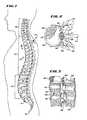
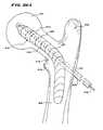
- FIG. 1is a side view of the spinal column of a human
- FIG. 2is coronal view of a lumbar vertebra, partially cut away and in section, taken generally along line 2 — 2 in FIG. 1 ;
- FIG. 3is a vertical section of lumbar vertebrae
- FIG. 4is a plan view of a probe including a catheter tube carrying an expandable body intended to treat bone;
- FIGS. 5A to 5 Pare a series of coronal views of a vertebra, partially cut away and in section, showing the steps of introducing, via transpedicular access, an expandable body to compress cancellous bone and create a cavity within a vertebral body, and of then conveying a filling material into the cavity to restore interior integrity to cortical bone;
- FIG. 5Qis a lateral view, with parts broken away, of the vertebra shown in coronal view in FIG. 5P ;
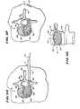
- FIG. 6is a coronal view of a vertebral body in which an expandable body, restrained by an external sealing element, compresses cancellous bone to form a cavity;
- FIG. 7is a coronal view, partially broken away and in section, of a vertebral body in which an expandable body is being collapsed after having formed a cavity, while an injector tip, also within the vertebral body, is simultaneously injecting filling material into the cavity;
- FIG. 8Ais a coronal view of a vertebral body, partially broken away and in section, showing a tool that integrates an injector tube and an integral expandable body to create a cavity in cancellous bone, and also showing the injection of filling material simultaneous with collapse of the expandable body;
- FIG. 8Bis a side view of the tool shown in FIG. 8A , located outside bone;
- FIG. 8Cis sectional view of the tool shown in FIG. 8B , taken generally along line 8 C— 8 C in FIG. 8B ;
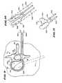
- FIG. 9is a coronal view of a vertebral body showing multiple expandable bodies separately introduced by transpedicular approach;
- FIG. 10is a view of the distal end of a probe in which two catheter tubes, each carrying an expandable body, are joined to form a symmetric array, when substantially expanded outside a bone;
- FIG. 11is a view of the distal end of a probe in which two catheter tubes, each carrying an expandable body, are joined to form an asymmetric array, when substantially expanded outside a bone;
- FIG. 12is a coronal view, partially broken away and in section, of a vertebral body into which multiple expandable bodies have been deployed by dual transpedicular access;
- FIG. 13is a coronal view of a vertebral body, partially broken away and in section, into which multiple expandable bodies have been deployed by contralateral posterolateral access;
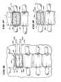
- FIG. 14is a coronal view of a vertebral body, partially broken away and in section, in which multiple expandable bodies have formed multiple cavities which join to form a single cavity to receive filling material;
- FIG. 15is a coronal view of a vertebral body, partially broken away and in section, in which multiple expandable bodies have formed multiple separate cavities to receive filling material;
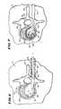
- FIG. 16is an anterior-posterior view of a region of the spine, showing multiple expandable bodies present within a targeted vertebral body using ipsilateral postereolateral access;
- FIG. 17is an anterior-posterior view of a vertebral body, partially broken away and in section, in which multiple expandable bodies, introduced using ipsilateral postereolateral access, have formed multiple cavities which are joined to form a single cavity to receive filling material;
- FIG. 18is an anterior-posterior view of a vertebral body, partially broken away and in section, in which multiple expandable bodies, introduced using an ipsa posterolateral access, have formed multiple separate cavities to receive filling material;
- FIG. 19is a coronal view of a vertebral body, partially broken away and in section, in which multiple expandable bodies have been introduced by both transpedicular and posterolateral access;
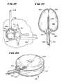
- FIG. 20is a perspective view of one representative embodiment of an expandable body having a stacked doughnut-shaped geometry
- FIG. 21is a view of another representative embodiment of an expandable body having an oblong-shaped geometry
- FIG. 22is an elevation view of another representative embodiment of an expandable body showing three stacked bodies and string-like restraints for limiting the expansion of the bodies during inflation;
- FIG. 23is a perspective view of another representative embodiment of an expandable body having a kidney bean-shaped geometry
- FIG. 24is a top view of another representative embodiment of an expandable body having a kidney bean-shaped geometry with several compartments by a heating element or branding tool;
- FIG. 25is a cross-sectional view taken along line 25 — 25 of FIG. 24 ;
- FIG. 26is a perspective, lateral view of a vertebral body, partially broken away to show the presence of an expandable body, and also showing the major reference dimensions for the expandable body;
- FIG. 27is a dorsal view of a representative expandable body having a humpback banana-shaped geometry in use in a right distal radius;
- FIGS. 28is a cross sectional view of the expandable body shown in FIG. 27 , taken generally along line 28 — 28 of FIG. 27 ;
- FIG. 29Ais a representative expandable body having a spherical shape with a base, located in a proximal humerus and viewed from the front (anterior) of the left proximal humerus;
- FIG. 29Bis a representative expandable body having a cylindrical shape, located in a proximal humerus and viewed from the front (anterior) of the left proximal humerus;
- FIG. 30Ais a representative embodiment of an expandable body located, as shown in a front (anterior) view of the proximal tibia, introduced beneath the medial tibial plateau;
- FIG. 30Bis a side elevation view of the expandable body shown in FIG. 3 OA;
- FIG. 30Cis a top perspective view of the expandable body shown in FIG. 30A , showing its generally cylindrical geometry;
- FIG. 31is a top plan view of another representative embodiment of an expandable body for use in treating tibial plateau fractures, having a generally elliptical geometry;
- FIG. 32is a side view of multiple expandable bodies stacked on atop another for use, for example, in treating tibial plateau fractures;
- FIG. 33is another representative embodiment of an expandable body having an egg-shaped geometry located, as shown in a front (anterior) view of the proximal tibia, introduced beneath the medial tibial plateau;
- FIG. 34is a representative embodiment of an expandable body having a spherical-shaped geometry for treating avascular necrosis of the head of the femur (or humerus), which is shown from the front (anterior) of the left hip;
- FIG. 35is a side view of another representative embodiment of an expandable body having a hemispherically-shaped geometry for treating avascular necrosis of the head of the femur (or humerus);
- FIG. 36Ais a view of a representative expandable body having a bent-geometry for preventing hip fracture, as seen from the front (anterior) of the left hip;
- FIG. 36Bis a view of multiple expandable bodies individually deployed through multiple access points into the left hip for preventing hip fracture;
- FIG. 37Ais a view of a representative expandable body having an asymmetric bow tie-shape for use in treating fracture of the calcaneus bone, shown in lateral view within the calcaneus;
- FIG. 37Bis a perspective top view of the expandable body shown in FIG. 37A when substantially expanded outside the calcaneus;
- FIG. 38shows a representative embodiment of an expandable body having a spherical or egg-shaped geometry shown in lateral view deployed within the calcaneus;
- FIGS. 39A to 39 Dshow a multiple stage process of introducing filling material into a cavity formed by an expandable body in cancellous bone, to prevent or impede flow or seepage of filling material from the interior of the bone;
- FIG. 40is an elevation view of an injector tip for filling material, over which a mesh is draped, which, when deployed in a cavity formed by an expandable body, impedes or prevents seepage of the material from the cavity;
- FIG. 41is a coronal view of a vertebra, with parts broken away and in section, showing the deployment of the mesh shown in FIG. 40 within the vertebral body;
- FIGS. 42A to 42 Care schematic illustrations of a representative method and system for delivering a therapeutic substance to a bone using an expandable body
- FIG. 43is an illustration of the human skeleton, showing regions of long bone that can be treated using expandable bodies
- FIG. 44is a representative embodiment of multiple expandable bodies located, as shown in a front (anterior) view, within the proximal tibia, both introduced beneath the medial tibial plateau, one of the bodies being substantially expanded to form an interior barrier and serve as a platform for the other body, which is shown substantially collapsed;
- FIG. 45is a front (anterior) view of the multiple expandable bodies, shown in FIG. 44 , with both bodies in substantially expanded conditions to form a cavity within the proximal tibia beneath the medial tibial plateau;
- FIG. 46is an enlarged front (anterior) perspective view of the multiple expandable bodies shown in FIG. 45 , with the lower expandable body serving as a platform for the upper expandable body;
- FIG. 47is diagrammatic view of a system for harvesting bone marrow in a bone-marrow producing bone using an expandable body
- FIG. 48is a section view of the catheter tube associated with the system shown in FIG. 48 , taken generally along line 48 — 48 of FIG. 47 ;
- FIG. 49is an enlarged view of the expandable body associated with the system shown in FIG. 47 inside a bone for the purpose of harvesting bone marrow.
- the spinal column 10comprises a number of uniquely shaped bones, called the vertebrae 12 , a sacrum 14 , and a coccyx 16 (also called the tail bone).
- the number of vertebrae 12 that make up the spinal column 10depends upon the species of animal. In a human (which FIG. 1 shows), there are twenty-four vertebrae 12 , comprising seven cervical vertebrae 18 , twelve thoracic vertebrae 20 , and five lumbar vertebrae 22 .
- the spinal column 10When viewed from the side, as FIG. 1 shows, the spinal column 10 forms an S-shaped curve.
- the curveserves to support the head, which is heavy. In four-footed animals, the curve of the spine is simpler.
- each vertebra 12includes a vertebral body 26 , which extends on the anterior (i.e., front or chest) side of the vertebra 12 .
- the vertebral body 26is in the shape of an oval disk.
- the vertebral body 26includes an exterior formed from compact cortical bone 28 .
- the cortical bone 28encloses an interior volume 30 of reticulated cancellous, or spongy, bone 32 (also called medullary bone or trabecular bone).
- a “cushion,” called an intervertebral disk 34is located between the vertebral bodies 26 .
- the spinal ganglion 39pass through the foramen 36 .
- the spinal cord 38passes through the spinal canal 37 .
- the vertebral arch 40surrounds the spinal canal 37 .
- the pedicle 42 of the vertebral arch 40adjoins the vertebral body 26 .
- the spinous process 44extends from the posterior of the vertebral arch 40 , as do the left and right transverse processes 46 .
- FIG. 4shows a tool 48 for preventing or treating compression fracture or collapse of a vertebral body using an expandable body.
- the tool 48includes a catheter tube 50 having a proximal and a distal end, respectively 52 and 54 .
- the distal end 54carries an expandable body 56 .
- the body 56includes an exterior wall 58 , which, in FIG. 4 , is shown in a collapsed geometry.
- the collapsed geometrypermits insertion of the body 56 into the interior volume 30 of a targeted vertebral body 26 .
- FIGS. 5A to 5 Qshow the insertion of the body 56 using a transpedicular approach, which can be performed either with a closed, mininimally invasive procedure or with an open procedure.
- a patientlies on an operating table, while the physician introduces a conventional spinal needle assembly 60 into soft tissue in the patient's back.
- the patientcan lie facedown on the table, or on either side, or at an oblique angle, depending upon the physician's preference.
- the procedurecan be performed through an open anterior procedure or an endoscopic anterior procedure, in which case the tool 48 may be introduced from the anterior aspect of the vertebral body.
- the spinal needle assembly 60comprises a stylet 62 slidable housed within a stylus 64 .
- the assembly 60typically has, for example, about an 18 gauge diameter. Other gauge diameters can and will be used to accommodate appropriate guide pins, as will be described in greater detail later.
- the physicianadvances the assembly 60 through soft tissue (designated S in FIG. 5A ) down to and into the targeted vertebra 12 , as FIG. 5A shows.
- the physicianwill typically administer a local anesthetic, for example, lidocaine, through assembly 60 .
- a local anestheticfor example, lidocaine
- the physicianmay prefer other forms of anesthesia.
- the physiciandirects the spinal needle assembly 60 to penetrate the cancellous bone 32 of the targeted vertebra 12 .
- the depth of penetrationis about 60% to 95% of the vertebral body 26 .
- FIG. 5Ashows gaining access to cancellous bone 32 through the pedicle 42 , which is called transpedicular access.
- posterolateral accessthrough the side of the vertebral body 12 (designated P-L and shown in phantom lines in FIG. 5 A), may be indicated, if a compression fracture has collapsed the vertebral body 26 below the plane of the pedicle 42 , or for other reasons based upon the preference of the physician.
- the physicianAfter positioning the spinal needle assembly 60 in cancellous bone 32 , the physician holds the stylus 64 and withdraws the stylet 62 (see FIG. 5 B). Still holding the stylus 64 , the physician slides a guide pin 66 through the stylus 64 and into the cancellous bone 32 (see FIG. 5 C). The physician now removes the stylus 64 , leaving the guide pin 66 deployed within the cancellous bone 32 , as FIG. 5D shows.
- the physicianmakes a small incision (designated I in FIG. 5E ) in the patient's back to accommodate a trocar 68 .
- the physicianinserts the trocar 68 through the soft tissue S along the guide pin 66 down to the pedicle 42 .
- the physiciantaps the distal end 70 of the trocar 68 into the pedicle 42 to secure its position.
- FIG. 5Fshows, the physician next slides an outer guide sheath 72 over the trocar 68 .
- the distal end 74 of the outer guide sheath 72is likewise tapped into the pedicle 42 .
- the physicianremoves the trocar 68 , leaving the guide pin 66 and outer guide sheath 72 in place, as FIG. 5G shows.
- the trocar 68 and guide sheath 72can be introduced together in one step.
- the physicianadvances a drill bit 76 (for example, 5 mm in diameter) over the guide pin 66 through the outer guide sheath 72 .
- a drill bit 76for example, 5 mm in diameter
- the physicianoperates the drill bit 76 to open a passage 78 through the pedicle 42 and into the cancellous bone 32 .
- the drilled passage 78preferable extends no more than 95% across the vertebral body 26 .
- the physicianremoves drill bit 76 and guide pin 66 , leaving the outer guide sheath 72 .
- the passage 78 made by the drill bit 76remains, passing through the pedicle 42 and into the cancellous bone 32 .
- FIG. 5 J( 1 )shows, the physician next advances the catheter tube 50 and expandable body 56 through the outer guide sheath 72 and into the drilled passage 78 in the cancellous bone 32 .
- the body 56is maintained in a straightened, collapsed condition distally beyond the end of the catheter tube 50 during transport through the guide sheath 72 and into the drilled passage 78 by a generally rigid, external protective sleeve 73 , which surrounds the body 56 .
- an internal stiffening membercan extend within the body 56 , to keep the body 56 in the desired distally straightened condition during passage through the guide sheath 72 .
- the physicianpulls the sleeve 73 back, to uncover the body 56 .
- the expandable body 56can be dipped into thrombin prior to its introduction into the vertebral body 26 to facilitate in situ coagulation.
- the materials for the catheter tube 50are selected to facilitate advancement of the body 56 into cancellous bone through the guide sheath 72 .
- the catheter tube 50can be constructed, for example, using standard flexible, medical grade plastic materials, like vinyl, nylon, polyethylenes, ionomer, polyurethane, and polyethylene tetraphthalate (PET).
- PETpolyethylene tetraphthalate
- the catheter tube 50can also include more rigid materials to impart greater stiffness and thereby aid in its manipulation. More rigid materials that can be used for this purpose include KevlarTM material, PEBAXTM material, stainless steel, nickel-titanium alloys (NitinolTM material), and other metal alloys.
- the wall 58 of the body 56is capable of assuming an expanded geometry within the interior volume 30 (generally shown in FIG. 5 K( 1 )).
- the catheter tube 50includes a first interior lumen 80 (see FIG. 4 ).
- the lumen 80is coupled at the proximal end of the catheter tube 50 to a pressurized source of fluid 82 .
- the fluid 82is preferably radio-opaque to facilitate visualization.
- RenograffinTMcan be used for this purpose.
- the lumen 80conveys the fluid 82 into the body 56 under pressure.
- the wall 58expands, as FIG. 5 K( 1 ) shows.
- body expansioncan be monitored fluoroscopically or under CT visualization.
- the body 56may be filled with sterile water, saline solution, or sugar solution.
- Expansion of the wall 58enlarges the body 56 and compacts cancellous bone 32 within the interior volume 30 .
- the presence of the sheath 73serves to keep the proximal end of the body 56 away from edge-contact with the distal end of the catheter tube 50 .
- the compaction of cancellous bone 32forms a cavity 84 in the interior volume 30 of the vertebral body 26 .
- the compaction of cancellous bonealso exerts interior force upon cortical bone, making it possible to elevate or push broken and compressed bone back to or near its original prefracture position.
- the cavity 84occupies about one-half of the interior volume 30 .
- a cavity 84 occupying substantially all of the interior volume 30can be created.
- the proximal end of the catheter tube 50is preferably coupled by tubing to a source of negative air pressure 86 .
- the negative pressureis conveyed through a second interior lumen 81 to one or more suction holes 88 on the distal end of the catheter tube 50 .
- suctionis applied to remove fats and other debris through the suction holes 88 for disposal.
- a separate suction-irrigation toolcan be deployed through the guide sheath 72 for this purpose, if desired.
- the body 56is preferably left inflated for an appropriate waiting period, for example, three to five minutes, to allow coagulation inside the vertebral body 26 .
- the physiciancollapses the body 56 and removes it through the outer guide sheath 72 (see FIG. 5 L).
- the exterior surface of the body 56can be treated, e.g., by ion beam-based surface treatment, to reduce friction during passage through the outer guide sheath 72 .
- FIG. 5Lshows, upon removal of the body 56 , the formed cavity 84 remains in the interior volume 30 .
- a suction-irrigation tool(not shown) can be introduced through the outer guide sheath 72 , to further flush and clear debris from the formed cavity 84 after removal of the body 56 .
- an injector nozzle or tip 90coupled by an injector tube 92 to an injector gun 94 , is inserted through the outer guide sheath 72 into the formed cavity 84 .
- the injector gun 94carries a filling material 96 .
- the filling material 96comprises, for example, methylmethacrylate cement or a synthetic bone substitute.
- the injector gun 94can comprise a cement gun made, for example, by Stryker Corporation (Kalamazoo, Mich.). This particular injector gun 94 has a manually operated injection grip 98 with a mechanical advantage of about 9 to 1. Other injection guns may be used, having more or less mechanical advantage. Non-manually operated injection guns can also be used.
- the injector tip 90can be, for example, about 4.9 mm in diameter, to accommodate the flow a relatively viscous material 96 into the cavity 84 .
- the injector gun 94pushes the filling material 96 into the cavity 84 .
- the physicianpreferably begins with the injector tip 90 positioned at the anterior region of the cavity 84 (as FIG. 5M shows). The physician progressively moves the tip 90 toward the posterior region of the cavity 84 (as FIG. 5N shows), away from the flow of the material 96 as it enters and fills the cavity 84 . The physician observes the progress of the injection fluoroscopically.
- the physiciancan also check, using, for example, x-ray, for leakage of the material through cortical bone 28 .
- Systems and methods for impeding or preventing such leakagewill be described in greater detail later.
- the physicianflows material 96 into the cavity 84 , until the material 96 reaches the distal end 74 of the outer guide sheath 72 (as FIG. 50 shows).
- the physicianmay, if necessary, tamp residual filling material 96 from the distal end 74 of the outer guide sheath 72 into the cavity 84 . If fluoroscopic examination reveals void regions in the cavity 84 , the physician may again insert the injector tube 92 to add more filling material 96 into the cavity 84 .
- FIG. 7shows an alternative technique for filling the cavity.
- the injector tip 90occupies the cavity 84 while the expandable body 56 is collapsing within the cavity 84 .
- the tip 90injects material 96 into the part of the cavity 84 that the collapsing body 56 no longer occupies.
- the increasing volume of the cavity 84 not occupied by the collapsing body 56is thereby progressively filled by an increasing volume of material 96 .
- the presence of the body 56partially expanded while the tip 90 injects the material 96 , serves to compact and spread the injected material 96 within the cavity 84 .
- the physicianprogressively retracts the injector tip 90 from the anterior region of the cavity 84 , toward the outer guide sheath 72 , allowing the material 96 to progressively enter and fill the cavity 84 with the collapse of the body 56 .
- FIGS. 8A to 8 Cshow a preferred embodiment of a tool 650 which integrates the injection tube and expandable body in a single structure.
- the tool 650includes a catheter tube 652 having a proximal end 654 and a distal end 656 .
- the distal endcarries an expandable body 662 .
- the catheter tube 652has concentric inner and outer lumens, respectively 658 and 660 .
- the inner lumen 658communicates, by proximal tubing 664 , with an injector gun 94 , of the type previously described.
- the inner lumen 658also communicates with an injector nozzle or tip 666 at the distal catheter tube end 656 . Operation of the gun 94 serves to inject filling material 96 through the nozzle 666 (as FIG. 8A shows).
- the outer lumen 660communicates, via proximal tubing 668 , with a source 82 of pressurized liquid.
- the outer lumen 660also communicates with ports 670 formed on the distal catheter tube end 656 underlying the expandable body 662 . Operation of the source 82 serves to inject pressurized liquid into the body 662 to expand it, in the manner previously described.
- the physicianintroduces the tool 650 into the cancellous bone 32 .
- the physicianexpands the body 662 to create the cavity 84 .
- the physicianbegins to collapse the body 662 , while injecting the filling material 96 through the nozzle 666 .
- the volume of the cavity 84 occupied by the collapsing body 662is progressively filled by the increasing volume of filling material 96 injected through the nozzle 666 .
- the collapsing body 662serves to compact and spread the filling material 96 more uniformly within the cavity 84 .
- the physicianprogressively retracts the distal end 656 of the tool 650 from the anterior region of the cavity 84 toward the outer guide sheath 72 , allowing the material 96 to enter and fill the cavity 84 .
- FIGS. 5P and 5Qshow.
- the incision siteis sutured or otherwise closed (designated by ST in FIG. 5 P).
- the filling material 96sets to a hardened condition within the cavity 84 (see FIGS. 5 P and 5 Q).
- the hardened material 96provides renewed interior structural support for the cortical bone 28 .
- the above described procedure, carried out in a minimally invasive manner,can also be carried out using an open surgical procedure.
- open surgerythe physician can approach the bone to be treated as if the procedure is percutaneous, except that there is no skin and other tissues between the surgeon and the bone being treated. This keeps the cortical bone as intact as possible, and can provide more freedom in accessing the interior volume 30 of the vertebral body.
- the material of the body wall 58can be selected according to the therapeutic objectives surrounding its use. For example, materials including vinyl, nylon, polyethylenes, ionomer, polyurethane, and polyethylene tetraphthalate (PET) can be used.
- PETpolyethylene tetraphthalate
- the thickness of the body wall 58is typically in the range of ⁇ fraction (2/1000) ⁇ ths to ⁇ fraction (25/1000) ⁇ ths of an inch, or other thicknesses that can withstand pressures of up to, for example, 250-500 psi.
- the material for the wall 58can be selected to exhibit generally elastic properties, like latex.
- the materialcan be selected to exhibit less elastic properties, like silicone.
- expandable bodies 56 with generally elastic or generally semi-elastic propertiesthe physician monitors the expansion to assure that over-expansion and wall failure do not occur.
- expandable bodies 56 with generally elastic or generally semi-elastic propertieswill require some form of external or internal restraints to assure proper deployment in bone.
- expandable bodies 56 with generally elastic propertieswill exhibit the tendency to backflow or creep into the outer guide sheath 72 during their expansion. It is therefore necessary to internally or externally restrain a body 56 that is subject to creeping, to keep it confined within the interior bone region.
- an exterior sealing element 100is provided for this purpose.
- the sealing element 100takes the form of a movable o-ring.
- the physicianadvances the o-ring 100 along the catheter tube 50 inside the guide sheath 72 using a generally stiff stylet 102 attached to the o-ring 100 .
- the physicianlocates the o-ring 100 at or near the distal end 54 of the catheter tube 50 prior to conveying the liquid 82 to expand the body 56 .
- the o-ring 100is held in place by the generally stiff stylet 102 , which provides a counter force to prevent backward movement of the o-ring 100 in the guide sheath 72 as the body 56 expands.
- the o-ring 100thereby keeps all or a substantial portion of the generally elastic body 26 confined inside the interior volume 30 .
- the body 56thereby serves to compact as much of the cancellous bone 32 as possible.
- an external sealing element 100 to restrain the expandable body 56may not be necessary when relatively inelastic materials are selected for the body 56 .
- the material for the body wall 58can be selected to exhibit more inelastic properties, to limit expansion of the wall 58 prior to wall failure.
- the body wall 58can also include one or more restraining materials, particularly when the body wall 58 is itself made from more elastic materials.
- a predetermined shape and sizecan be imparted to the body 56 , when it is substantially expanded.
- the shape and sizecan be predetermined according to the shape and size of the surrounding cortical bone 28 and adjacent internal structures, or by the size and shape of the cavity 84 desired to be formed in the cancellous bone 32 .
- the shape and size of the body 56when substantially expanded, can be designed to occupy at least about 30% of the volume of cancellous bone 32 in the interior volume 30 .
- a body 56 having a substantially expanded size and shape in the range of about 40% to about 99% of the cancellous bone volumeis preferred.
- the shape and size of the body 56can be designed to occupy as little as about 10% of the cancellous bone volume.
- the drilled passage 78extends directly to the localized site of injury, to enable targeted introduction of the body 26 .
- the shape of the cancellous bone 32 to be compressed, and the presence of surrounding local anatomic structures that could be harmed if cortical bone were moved inappropriately,are generally understood by medical professionals using textbooks of human skeletal anatomy, along with their knowledge of the site and its disease or injury.
- the physicianis also able to select the materials and geometry desired for the body 56 based upon prior analysis of the morphology of the targeted bone using, for example, plain films, spinous process percussion, or MRI or CRT scanning.
- the materials and geometry of the body 56are selected to create a cavity 84 of desired size and shape in cancellous bone 32 without applying harmful pressure to the outer cortical bone 28 or surrounding anatomic structures.
- Such movementis not per se harmful, as that term is used in this Specification, because it is indicated to achieve the desired therapeutic result.
- harmresults when expansion of the body 56 results in a worsening of the overall condition of the bone and surrounding anatomic structures, for example, by injury to surrounding tissue or causing a permanent adverse change in bone biomechanics.
- Formation of a desired cavity geometry in cancellous bone 32 using an expandable body 56can be accomplished in diverse ways to achieve the desired therapeutic effect.
- the foregoing disclosureenvisions the deployment of a single expandable body 56 to compact cancellous bone 32 and, by itself, form a cavity 84 having a desired shape and size to receive a filling material 96 .
- a cavity 84 having a desired shape and size in cancellous bone 32can be formed by the deployment of more than one expandable body 56 in a targeted region of cancellous bone 32 , either sequentially or simultaneously.
- FIG. 9shows the representative deployment of multiple expandable bodies 56 A and 56 B through a single outer guide sheath 72 , which is arranged to provide transpedicular access. It should be understood that deployment of multiple expandable bodies can likewise be achieved through an outer guide sheath 72 arranged to provide a posterolateral access, through the side of the vertebral body 26 (as shown as P-L in phantom lines in FIG. 9 ).
- the expandable bodies 56 A and 56 Bare carried by separate catheter tubes 50 A and 50 B, which are not joined together.
- a tool 109comprising an array 108 of catheter tubes 50 A and 50 B is provided.
- Each catheter tube 50 A and 50 Beach carries an expandable body 56 A and 56 B, which are shown in FIG. 10 in a collapsed condition.
- the distal ends of the catheter tubes 50 A and 50 Bare joined by a connector 106 , for simultaneous deployment through an outer guide sheath 72 into the vertebral body 26 , as FIG. 9 shows.
- a slidable protective sheath 73encloses the bodies 56 A and 56 B during passage through the guide sheath 72 .
- the connector 106can permit relative adjustment of the catheter tubes 50 A and 50 B, so that, when deployed, one expandable body is located more distal to another expandable body.
- FIGS. 9 and 10show two catheter tubes 50 A and 50 B, but more than two catheter tubes can be deployed in the vertebral body 26 , either as separate tools (as FIG. 9 shows), or joined to form a composite array 108 (as FIG. 10 shows).
- the bodies 56 A and 56 B of the array 108have generally the same geometry, when substantially expanded, thereby providing a symmetric arrangement for compacting cancellous bone 32 .
- a generally symmetric cavity 84results.
- the bodies 56 A and 56 Bpossess different geometries when substantially expanded, thereby presenting an asymmetric arrangement for compacting cancellous bone 32 .
- a generally asymmetric cavity 84results.
- the selection of size and shape of the array 108depends upon the size and shape of the targeted cortical bone 28 and adjacent internal structures, or by the size and shape of the cavity 84 desired to be formed in the cancellous bone 32 .
- the deployment of multiple expandable bodies 56makes it possible to form cavities 84 having diverse and complex geometries within bones of all types. Multiple expandable bodies having generally the same geometry can be deployed in different ways to create cavities of different geometries.
- FIGS. 9 to 11show the various styles of multiple expandable bodies 56 shown in FIGS. 9 to 11 by using, e.g., a relatively stiff, surrounding sheath 73 (shown in phantom lines in FIG. 10 ), which is manipulated in the same as previously described in connection with FIGS. 5 J( 1 ) and 5 J( 2 ).
- a relatively stiff, surrounding sheath 73shown in phantom lines in FIG. 10
- Access for expandable bodies 56can be achieved through multiple access sites and in many different ways.
- multiple expandable bodiescan access the vertebral body from different regions of a targeted vertebra.
- FIG. 12shows a representative dual transpedicular access, in which two outer guide sheaths 72 A and 72 B are used to provide separate access for two or more expandable bodies 56 A and 56 B through different sides of the pedicle 42 A and 42 B of the vertebral body 26 .
- FIG. 13shows a representative dual contra lateral posterolateral access, in which two outer guide sheaths 72 A and 72 B are used to provide separate access for multiple expandable bodies 56 A and 56 B from different lateral sides of the vertebral body 26 .
- the multiple expandable bodies 56 A and 56 Beach forms a cavity 84 A and 84 B (shown in FIG. 14 ).
- the cavities 84 A and 84 Bare transversely spaced within the cancellous bone 32 .
- the transversely spaced cavities 84 A and 84 Bmay adjoin to form a single combined cavity (designated C in FIG. 14 ), into which the filling material 96 is injected.
- the transversely spaced cavities 84 A and 84 Bmay remain separated by a region of cancellous bone (designated by numeral 110 in FIG. 13 ). In this arrangement, the filling material 96 is injected into multiple, individual cavities 84 A and 84 B within the interior volume.
- FIG. 16shows a representative dual ipsilateral posterolateral access, in which two outer guide sheaths 72 A and 72 B are used to provide separate access from the same lateral sides of the vertebral body 26 .
- the multiple expandable bodies 56 A and 56 Bform vertically spaced, or stacked, cavities 84 A and 84 B.
- the vertically spaced cavities 84 A and 84 Bmay adjoin to form a single combined cavity (designated C in FIG. 17 ), into which the filling material 96 is injected.
- the vertically spaced cavities 84 A and 84 Bmay be separated by a region of cancellous bone (designated by numeral 110 in FIG. 18 ), forming multiple individual cavities 84 A and 84 B within the interior volume, each of which is individually filled with a filling material 96 A and 96 B.
- FIG. 19shows a first outer guide sheath 72 A arranged to provide a transpedicular access and a second outer guide sheath 72 B to provide a posterolateral access.
- Systems for treating bone using multiple expandable bodiescan include directions 79 (see FIG. 12 ) for deploying the first and second expandable bodies.
- the directions 79can instruct the physician to insert a first expandable body into the interior volume through a first access path through cortical bone, while inserting a second expandable body into the interior volume through a second access path through cortical bone different than the first access path.
- each guide sheath 72 A or 72 Bcan itself accommodate a single expandable body or multiple expandable bodies.
- the size and shape of the bodiesmay be the same, or they may vary, according to the desired objectives of the physician for the targeted vertebral body.
- FIG. 20shows a representative embodiment of an expandable body, which is broadly denoted by the numeral 210 .
- the body 210comprises a pair of hollow, inflatable, non-expandable parts 212 and 214 of flexible material, such as PET or Kevlar.
- Parts 12 and 14have a suction tube 216 therebetween for drawing fats and other debris by suction into tube 216 for transfer to a remote disposal location.
- the catheter tube 216has one or more suction holes so that suction may be applied to the open end of tube 216 from a suction source (not shown).
- Parts 212 and 214are connected together by an adhesive which can be of any suitable type.
- Parts 212 and 214are doughnut-shaped, as shown in FIG. 20 and have tubes 218 and 220 which communicate with and extend away from the parts 212 and 214 , respectively, to a source of inflating liquid under pressure (not shown). The liquid expands the body 210 as already described.
- FIG. 21shows a modified doughnut shape body 280 of the type shown in FIG. 20 , except the doughnut shapes of body 280 are not stitched onto one another.
- body 280has a pear-shaped outer convex surface 282 which is made up of a first hollow part 284 and a second hollow part 285 .
- a tube 288is provided for directing liquid into the two parts along branches 290 and 292 to inflate the parts after the parts have been inserted into the interior volume of a bone.
- a catheter tube 216may or may not be inserted into the space 296 between two parts of the balloon 280 to provide irrigation or suction.
- An adhesivebonds the two parts 284 and 285 together.
- FIG. 22shows another representative embodiment of an expandable body, designated 309 .
- the body 309has a generally round geometry and three expandable body units 310 , 312 and 314 .
- the body units 310 , 312 , and 314include string-like external restraints 317 , which limit the expansion of the body units 310 , 312 , and 314 in a direction transverse to the longitudinal axes of the body units 310 , 312 , and 314 .
- the restraints 317are made of the sane or similar material as that of the body units 310 , 312 , and 314 , so that they have some resilience but substantially no expansion capability.
- a tubes 315direct liquid under pressure into the body units 310 , 312 and 314 to expand the units and cause compaction of cancellous bone.
- the restraints 317limit expansion of the body units prior to failure, keeping the opposed sides 377 and 379 substantially flat and parallel with each other.
- FIG. 23shows another representative embodiment of an expandable body 230 , which has a kidney-shaped geometry.
- the body 230has a pair of opposed kidney-shaped side walls 232 and a continuous end wall 234 .
- a tube 238directs liquid into the body to expand it within the vertebral body.
- FIG. 24shows another representative embodiment of an expandable body 242 , which also has a kidney-shaped geometry.
- the body 242is initially a single chamber bladder, but the bladder is branded along curved lines or strips 241 to form attachment lines 244 which take the shape of side-by-side compartments 246 which are kidney shaped as shown in FIG. 25.
- a similar pattern of strips as in 240 but in straight lineswould be applied to a body that is square or rectangular.
- the brandingcauses a welding of the two sides of the bladder to occur.
- the eventual selection of the size and shape of a particular expandable body or bodies to treat a targeted vertebral body 26is based upon several factors. When multiple expandable bodies are used, the total combined dimensions of all expandable bodies deployed, when substantially expanded, should be taken into account.
- the anterior-posterior (A-P) dimension(see FIG. 26 ) for the expandable body or bodies is selected from the CT scan or plain film or x-ray views of the targeted vertebral body 26 .
- the A-P dimensionis measured from the internal cortical wall of the anterior cortex to the internal cortical wall of the posterior cortex of the vertebral body.
- the appropriate A-P dimension for the expandable body or bodiesis less than this anatomic measurement.
- the appropriate side to side dimension L (see FIG. 26 ) for an expandable body or bodiesis also selected from the CT scan, or from a plain film or x-ray view of the targeted vertebral body.
- the side to side distanceis measured between the internal cortical walls laterally across the targeted vertebral body.
- the appropriate side to side dimension L for the expandable bodyis less than this anatomic measurement.
- the lumbar vertebral bodytends to be much wider in side to side dimension L then in A-P dimension. In thoracic vertebral bodies, the side to side dimension and the A-P dimensions are almost equal.
- the height dimensions H of the expandable body or bodiesis chosen by the CT scan or x-ray views of the vertebral bodies above and below the vertebral body to be treated.
- the height of the vertebral bodies above and below the vertebral body to be treatedare measured and averaged. This average is used to determine the appropriate height dimension of the chosen expandable body.
- expandable body or bodies for use in vertebraeare patient specific and will vary across a broad range, as summarized in the following table:
- a preferred expandable body 56 for use in a vertebral bodyis stacked with two or more expandable members of unequal height (see FIG. 26 ), where each member can be separately inflated through independent tube systems.
- the total height of the stack when fully inflatedshould be within the height ranges specified above.
- FIG. 43shows representative regions of the human skeleton 600 , where cancellous bone regions of long bones can be treated using expandable bodies.
- the regionsinclude the distal radius (Region 602 ); the proximal tibial plateau (Region 604 ); the proximal humerus (Region 606 ); the proximal femoral head (Region 608 ); and the calcaneus (Region 610 ).
- expandable bodiespossess the important attribute of being able, in the course of forming cavities by compressing cancellous bone, to also elevate or push broken or compressed cortical bone back to or near its normal anatomic position. This is a particularly important attribute for the successful treatment of compression fractures or cancellous bone fractures in the appendicular skeleton, such as the distal radius, the proximal humerus, the tibial plateau, the femoral head, hip, and calcaneus.
- expandable bodies for the treatment of cancellous bone regions of long boneswill be next described.
- FIGS. 27 and 28show a representative expandable body 260 for use in the distal radius.
- the body 260which is shown deployed in the distal radius 252 , has a shape which approximates a pyramid but more closely can be considered the shape of a humpbacked banana.
- the geometry of the body 260substantially fills the interior of the space of the distal radius to compact cancellous bone 254 against the inner surface 256 of cortical bone 258 .
- the body 260has a lower, conical portion 259 which extends downwardly into the hollow space of the distal radius 252 .
- This conical portion 259increases in cross section as a central distal portion 261 is approached.
- the cross section of the body 260is shown at a central location (FIG. 27 ), which is near the widest location of the body 260 .
- the upper end of the body 260denoted by the numeral 262 , converges to the catheter tube 288 for directing a liquid into the body 260 to expand it and force the cancellous bone against the inner surface of the cortical bone.
- the shape of the body 260is determined and restrained by tufts formed by string restraints 265 . These restraints are optional and provide additional strength to the body 260 , but are not required to achieve the desired configuration.
- the body 260is placed into and taken out of the distal radius in the same manner as that described above with respect to the vertebral bone.
- Typical dimensions of the distal radius bodyvary as follows:
- the proximal end of the body 260(i.e. the part nearest the elbow) is cylindrical in shape and will vary from 0.4 ⁇ 0.4 cm to 1.8 ⁇ 1.8 cm.
- the length of the distal radius bodywill vary from 1.0 cm to 12.0 cm.
- the widest medial to lateral dimension of the distal radius body, which occurs at or near the distal radio-ulnar joint,will measure from 0.5 cm to 2.5 cm.
- the distal anterior-posterior dimension of the distal radius bodywill vary from 0.4 to 3.0 cm.
- an appropriate expandable body 266 to treat a given proximal humeral fracturedepends on the radiologic size of the proximal humerus and the location of the fracture.
- FIG. 29Ashows a representative embodiment of an expandable body 266 for use in the proximal humerus 269 .
- the body 266is spherical for compacting the cancellous bone 268 in a proximal humerus 269 . If surrounding cortical bone has experienced depression fracture, expansion of the body 266 also serves to elevate or move the fractured cortical bone back to or near its anatomic position before fracture.
- a mesh 270embedded or laminated and/or winding, may be used to form a neck 272 on the body 266 .
- a second mesh 270 amay be used to conform the bottom of the base 272 a to the shape of the inner cortical wall at the start of the shaft.
- the body 266has a catheter tube 277 into which liquid under pressure is forced into the body to expand it to compact the cancellous bone in the proximal humerus.
- the body 266is inserted into and taken out of the proximal humerus in the same manner as that described above with respect to the vertebral bone.
- Typical dimensions of the expandable body 266 shown in FIG. 29A for proximal humerus fracturevary as follows:
- the spherical end of the bodywill vary from 0.6 ⁇ 0.6 cm to 3.0 ⁇ 3.0 cm.
- the neck of the proximal humeral fracture bodywill vary from 0.5 ⁇ 0.5 cm to 3.0 ⁇ 3.0 cm.
- the width of the base portion or distal portion of the proximal numeral fracture bodywill vary from 0.5 ⁇ 0.5 cm to 2.5 ⁇ 2.5 cm.
- the length of the bodywill vary from 3.0 cm to 14.0 cm.
- FIG. 29Bshows another representative embodiment of an expandable body 266 ′ for use in the proximal humerus 269 .
- the body 266 ′ shown in FIG. 29Bhas a generally cylindrical geometry for compacting the cancellous bone 268 in a proximal humerus 269 .
- the cylindrical body 266 ′can be elongated to form an elliptical or football-shaped geometry. Typical dimensions for a cylindrical or elliptical body vary from 0.6 cm to 3.0 cm in diameter to 3.0 cm to 14.0 cm in length.
- FIG. 30Ashows a representative expandable body 280 for treating a tibial plateau fracture.
- the body 280may be introduced into the tibia from any direction, as desired by the physician, for example, from the top, or medial, lateral, anterior, posterior, or oblique approach.
- the body 280has been introduced into cancellous bone 284 from the anterior side of the tibia 283 and is shown position in one side 282 of the tibia 283 .
- the body 280when substantially inflated (as FIG. 30A shows), compacts the cancellous bone in the layer 284 surrounding the body 280 . If the tibia plateau has experienced depression fracture, expansion of the body 280 also serves to move the tibia plateau back to or near its anatomic elevation before fracture, as FIG. 30A shows. Fractures on both the medial and lateral sides of the tibia can be treated in this manner.
- the body 280has a pair of opposed sides 285 and 287 .
- the sides 285 and 287are interconnected by restraints 288 , which pass through the body 280 .
- FIG. 30Cshows the tied-off ends 291 of the restraints 288 .
- the restraints 288can be in the form of strings or flexible members of any suitable construction.
- the restraints 288limit expansion of the body 280 prior to failure.
- the restraints 288make the sides 285 and 287 , when the body 280 is substantially expanded, substantially parallel with each other and, thereby, non-spherical.
- a tube 290is coupled to the body 280 to direct liquid into and out of the body to expand it.
- the bodyis inserted into and taken out of the tibia in the same manner as that described above with respect to the vertebral bone.
- FIG. 30Cshows a substantially circular configuration for the body 280 , although the body 280 can also be substantially elliptical, as FIG. 31 shows.
- two or more expandable bodies 280 ( 1 ), 280 ( 2 ), and 280 ( 3 )can be stacked one atop another to produce a different cavity geometry and to enhance plateau fracture displacement.
- the multiple bodies 280 ( 1 ), 280 ( 2 ), and 280 ( 3 )can comprise separate units or be joined together for common deployment. When deployed as separate units, the bodies 280 ( 1 ), 280 ( 2 ), and 280 ( 3 ) can enter through the same access point or from different access points.
- the body 280 ′can assume an egg shape when substantially inflated, to form a cavity and reshape broken bones.
- Other geometries, such as cylindrical or spherical,can also be used for the same purpose.
- Typical dimensions of the body 280 for treating proximal tibial plateau fracturevary as follows:
- the thickness or height of the bodywill vary from 0.3 cm to 5.0 cm.
- the anterior-posterior (front to back) dimensionwill vary from 1.0 cm to 6.0 cm.
- the medial to lateral (side-to-side) dimensionwill vary from 1.0 cm to 6.0 cm.
- FIGS. 44 and 45show multiple expandable zones 614 and 616 deployed in cancellous bone 620 .
- One zone 614serves as a platform to confine and direct the expansion of the other zone 616 .
- FIGS. 44 and 45show the multiple zones 614 and 616 used for this purpose to treat a tibial plateau fracture 622 .
- the zones 614 and 616comprise separate expandable bodies. It should be appreciated, however, that the zone 614 and 616 can comprise parts of a single expandable body.
- the first expandable body 614is deployed through a first outer guide sheath 618 ( 1 ) into cancellous bone 620 below the fracture 622 .
- the first body 614expands more along its horizontal axis 624 (i.e., in a side-to-side direction) than along its vertical axis 626 (i.e., in an top-to-bottom direction).
- the greater expanded side-to-side geometry of the first body 614compacts cancellous bone in a relatively thin region, which extends substantially across the interior volume 628 occupied by the first body 614 .
- the geometric limits of the body 614will typically fall just inside the inner cortical walls of the proximal tibia, or whatever bone in which the first body 614 is deployed.
- the expanded first body 614creates a barrier 630 within the interior region 628 . Due to the less expanded top-to-bottom geometry of the first body 614 , a substantially uncompacted region 632 of cancellous bone is left above the body 614 , which extends from the formed barrier 630 upward to the fracture 622 . In a representative deployment, the uncompacted region 632 extends about 2 cm below the tibial plateau fracture 622 .
- a second expandable body 616is deployed through a second outer guide sheath 618 ( 2 ) into the uncompacted region 632 left between the first body 614 , when substantially expanded, and the targeted tibial plateau fracture 622 .
- the second expandable body 616has a geometry, substantially like that shown in FIGS. 30A to 30 C.
- the second body 616When substantially inflated, the second body 616 compacts a large percentage of the cancellous bone in the region 632 above the first expandable body 614 .
- the presence of the barrier 630which the expanded first body 614 creates (see FIG. 46 also), prevents expansion of the second body 616 in a direction away from the tibial platform fracture 622 . Instead, the barrier 630 directs expansion of the second body 616 toward the fracture 622 . Buttressed by the barrier 630 , the expansion of the body 616 is directed against the fractured plateau 622 , restoring it to its normal anatomic position, as FIGS. 45 and 46 show.
- one or more expandable bodiescan be used as platforms or barriers to direct the expansion of one or more other expandable bodies in other localized interior bone regions.
- the barriermakes possible localized cavity formation in interior bone regions. Use of the barrier preserves healthy regions of cancellous bone, while directing the main compacting body toward localized fractures or localized regions of diseased cancellous bone.
- the size of an expandable body for use in the femoral head(Region 608 in FIG. 43 ) is chosen based upon the radiological or CT scan size of the head of the femur and the location and size of the avascular necrotic bone.
- FIG. 34shows a representative embodiment of an expandable body 300 introduced inside the cortical bone 302 of the femoral head.
- the femoral headis thin at the outer end 304 of the femur and increases in thickness at the lower end 306 of the femur.
- a tube 309directs liquid to expand the body 300 .
- the tube 309extends along the femoral neck and into the femoral head.
- the expandable body 300compacts the cancellous bone 307 in this bone region, while also moving fractured cortical bone back to or near its normal anatomic position.
- the femoral headis generally spherical in configuration, and the body 300 can have either a hemispherical (see FIG. 35 ) as well as spherical geometry (as FIG. 34 shows).
- the hemispherical shapeis maintained in FIG. 34 by bonding overlapping portions of the body 300 , creating pleats 300 b.
- the body 300is inserted into and taken out of the femoral head in the same manner as that described with respect to the vertebral bone.
- Typical dimensions of an expandable body for use in treating the femoral headvary as follows:
- the diameter of the expandable bodywill vary from 0.5 cm to up to 4.5 cm.
- the dimensions of the hemispherical bodyare the same as the those of the spherical body (FIG. 34 ), except that approximately one half is provided.
- FIG. 36Ashows a representative embodiment of an expandable body 410 having a “boomerang” geometry for use in preventing hip fracture.
- the body 410When substantially expanded (as FIG. 36A shows), the body 410 forms a cylinder, which gradually bends in the middle, like a boomerang, and extends from about 0.5 cm from the end of the femoral head 411 through the femoral neck 412 and down into the proximal femoral diaphysis 413 about 5 to 7 cm past the lesser trochanter 414 .
- Expansion of the body 410is limited to achieve the described geometry by rings 430 of inelastic material.
- the rings 430are held in a spaced apart relationship along one side of the body 410 by attachment to an inelastic band 416 , which runs the length of that side of body 410 .
- the rings 430are held in a farther spaced apart relationship along the opposite side of the body 410 by attachment to another, longer inelastic band 417 , which runs the length of the opposite side of the body 410 .
- a tube 419conveys liquid to inflate the body 410 .
- the body 410Prior to deployment within the body, the body 410 is collapsed and rolled up and held against the inflation tube 419 using, for example, with frangible connectors that will break as the body is subject to expansion.
- the surgeonuses a power drill under radiographic guidance to create a cavity 420 , which is, for example, about 4 to 6 mm wide starting at the lateral femoral cortex 421 and proceeding into the femoral head 411 .
- the body 410is deployed through a guide sheath 423 , following the cavity 420 .
- the body 410is deployed, prior to expansion, facing the lesser trochanter 414 , so that expansion occurs toward the femoral diaphysis 413 , and not toward the greater trochanteric region 422 .
- a second cavitycan be drilled down into the diaphysis 413 , starting from the same entry point or from the other side.
- the body lengthis chosen by the physician to extend about 0.5 cm from the end of the femoral head, through the femoral neck and into the proximal femoral diaphysis, usually about 4 to 8 cm below the lesser trochanter.
- the body diameteris chosen by measuring the inner cortical diameter of the femoral neck (the most narrow area) and subtracting 0.5 cm.
- the preferred dimensions of the body 410are a total length of 10-20 cm and a diameter of about 1.0-2.5 cm.
- Patients having the lowest bone densities in the femoral headmay require greater compacting in the femoral head, which may, for example, be provided by using two bodies, one after the other: the bent body 410 followed by the femoral head body (inserted at the same point and expanded prior to inserting any supporting material).
- the bent body 410may be adapted to have a distal portion that approximates the shape of the femoral head body.
- the geometry of the single, restrained body 410can be approximated by multiple expandable bodies deployed separately, or coupled together, or stacked together.
- FIG. 36Bshows a representative embodiment of the use of multiple expandable bodies in the hip region.
- a first expandable body 410 ( 1 )is introduced through a first outer guide sheath 423 ( 1 ) in the proximal lateral cortex of the femoral shaft.
- the first body 419 ( 1 )is deployed across the femoral neck 480 into the femoral head 482 .
- a second expandable body 410 ( 2 )is introduced through a second outer guide sheath 423 ( 2 ) in the greater trochanter 422 of the femur.
- the first body 419 ( 1 )is deployed in the direction of the femoral diaphysis 413 .
- one bodycan be introduced through the femoral neck 480 , and the other body can be introduced along the shaft of the femur.
- One or both of the bodies 410 ( 1 ) and 410 ( 2 )can include external restraints to limit expansion, in the manner described with regard to the body 410 . Expansion of the bodies 410 ( 1 ) and 410 ( 2 ) compacts cancellous bone to form a cavity having a geometry approximating that formed by the single body 410 .
- the size of an expandable body for use in treating fracture of the calcaneus(heel bone) (Region 610 in FIG. 43 ) is chosen based upon the radiological or CT scan size of the calcaneus and the location and size of the fracture.
- FIGS. 37A and 37Bshow a representative expandable body 450 for treating fracture of the calcaneus 452 .
- a tube 464conveys liquid into the body 450 to expand it.
- the body 450is deploy into the calcaneus 452 by a posterior approach, through the tuberosity.
- Other approachescan be used, as desired by the physician.
- a power drillopens a passage 466 through the tuberosity into the calcaneus.
- An outer guide sheath 470is positioned within the passage 466 , abutting the posterior of the calcaneus, in the manner previously described in obtaining access to a vertebral body.
- the body 450is introduced through the guide sheath 470 and formed passage 466 into the calcaneus.
- Expansion of the body 450is limited within the confines of the calcaneus by inelastic peripheral bands 454 (see FIG. 37 B).
- the bands 454constrain expansion of the body 450 to an asymmetric, pear-shaped geometry, best shown in FIG. 37 B.
- the pear-shaped geometryhas a major dimension H 1 occupying the region of the posterior facet 454 .
- the major dimension H 1is located here, because the part of the calcaneus most likely to require elevation and realignment during expansion of the body 450 is the depressed part of the posterior facet 454 of the calcaneus, where the posterior facet 454 abuts the talus 456 .
- the pear-shaped geometryhas a smaller, minor dimension occupying the region of the anterior facet 458 of the calcaneus, near the calcaneal-cuboid joint 460 , between the calcaneus and cuboid bone 462 .
- Expansion of the body 410compacts cancellous bone 470 within the calcaneus 452 .
- the expansionalso lifts a depression fracture of the posterior facet 454 back to or near its original anatomic elevation adjacent the talus 456 .
- the body 410leaves a cavity in cancellous bone into which filling material can be introduced in the manner previously described.
- FIG. 38shows another representative embodiment of an expandable body 450 ′ for use in treating fractures in the calcaneus.
- the body 450 ′ in FIG. 38has a more spherical or egg-shaped geometry than the pear-shaped body 450 shown in FIG. 37 B.
- the body 450 ′when expanded within the calcaneus, forms a cavity within cancellous bone and realigns fractured cortical bone at or near its normal anatomic position.
- expandable bodiesmay be used at sites not specified above, such as the jaw bones, the midshaft of the arm and leg bones, the cervical vertebral bodies, the foot and ankle bones, the pelvis, the ribs, and the like.
- the choice of the shape and size of a expandable bodytakes into account the morphology and geometry of the site to be treated. As before stated, the shape of the cancellous bone to be compressed, and the local structures that could be harmed if bone were moved inappropriately, are generally understood by medical professionals using textbooks of human skeletal anatomy along with their knowledge of the site and its disease or injury. Precise dimensions for a given patient can be further determined by X-ray of the site to be treated.
- the selection of the geometry of the expandable bodyshould take into account that at least 40% of the cancellous bone volume needs to be compacted in cases where the bone disease causing fracture (or the risk of fracture) is the loss of cancellous bone mass (as in osteoporosis).
- the preferred rangeis about 30% to 90% of the cancellous bone volume.
- the cancellous bonemay or may not be diseased or adversely affected. Healthy cancellous bone can be sacrificed by significant compaction to improve the delivery of a drug or growth factor which has an important therapeutic purpose.
- the size of the expandable bodyis chosen by the desired amount of therapeutic substance sought to be delivered.
- the bone with the drug insideis supported while the drug works, and the bone heals through exterior casting or current interior or exterior fixation devices.
- relatively inelastic properties for the expandable bodywhile not always required, is nevertheless preferred when maintaining a desired shape and size within the bone is important, for example, in bone graft placement or in a vertebral body, where the spinal cord is nearby.
- the shape and sizecan be better predefined, taking into account the normal dimensions of the outside edge of the cancellous bone.
- Use of relatively inelastic materialsalso more readily permits the application of pressures equally in all directions to compress cancellous bone.
- substantially equivalent resultscan usually be achieved by the use of multiple expandable bodies having highly elastic properties, if expansion is controlled by either internal or external restraints, as previously disclosed.
- FIG. 39Ashows at the anterior region of the vertebral body 26 .
- the failed cortical wall 28creates gaps and cracks (designated G in FIG. 39 A).
- remnant chips 500 of the failed cortical bone 28may lay in the cancellous bone 32 in the region where cortical wall failure has occurred. Filling material can flow or seep through these gaps or cracks C outside of the interior volume of the bone.
- the processbegins at the point where the outer guide sheath 72 has been positioned and the guide pin removed in the manner previously described.
- the physicianintroduces a first expandable body 502 into the cancellous bone 32 near the failed cortical bone region, as FIG. 39A shows.
- the first expandable body 502is sized, when substantially expanded, to occupy a relatively small volume (i.e., less than about 20%) of the volume of cancellous bone 32 in interior volume 30 .
- the physicianexpands the first expandable body 502 , compacting a relatively small region of cancellous bone.
- a small cavity 504caused by the compaction, remains (as FIG. 39B shows).
- the physicianintroduces the injector tip 90 and injects an aliquot of filling material 96 ( 1 ) (for example, about 1 cc to about 9 cc) into the formed small cavity 504 (as FIG. 39B shows).
- the physicianwithdraws the injector tip 90 and introduces a second expandable body 506 into the cancellous bone 32 (see FIG. 39 C).
- the second expandable body 506is larger than the first body 502 .
- the second body 506is sized to create the desired geometry for the therapeutic main cavity 508 in cancellous bone 32 .
- expansion of the second body 506displaces the earlier injected aliquot of filling material 96 ( 1 ) in the cavity 504 toward the failed cortical wall region.
- the aliquot of filling material 96 ( 1 )will envelop remnant chips 500 of cortical bone lying in its path.
- the material 96 ( 1 ) and enveloped chips 500are pressed against the failed cortical bone region as expansion of the second body 506 progresses.
- the first aliquot of filling material 96 ( 1 )will begin to set and harden as the main therapeutic cavity 508 is being formed by the expansion of the second body 506 .
- the second body 506is collapsed and removed, leaving the main cavity 508 .
- the first aliquot of filling material 96 ( 1 )provides a viscous or (in time) hardened boarder region along the anterior edge of the cavity 508 .
- the viscous or hardened boarder region 96 ( 1 )impedes passage of the additional filling material 96 ( 2 ) as it fills the main cavity 508 .
- the viscous or hardened boarder region 96 ( 1 )serves as a dam, keeping the additional filling material 96 ( 2 ) entering the main cavity 508 from seeping from the vertebral body 26 .
- FIGS. 40 and 41show the use of an interior mesh 510 in association with the introduction of filling material into a cavity formed by an expandable body in cancellous bone.
- the mesh 510is shown in association with treating a vertebral body, but it should be appreciated that the process can be used in the treatment of all bone types.
- FIG. 41shows at the anterior region of the vertebral body 26 ), coupled with the lack of enough bone matter, due to advanced disease or a complex fracture, to adequately fill the failed cortical bone region by compacting using an expandable body.
- Flowable cement materialcan flow or seep through the unfilled gaps or cracks (designated G in FIG. 41 ) present in the failed cortical bone region.
- the mesh 510comprises a woven structure made from biocompatible material like GoretexTM material, NitinolTM material, or DacronTM material.
- the meshpresents a surface area, which is about 1 ⁇ 3rd to 1 ⁇ 2 of the interior area of the main therapeutic cavity 84 formed by the selected expandable body.
- the physiciandrapes the mesh 510 over the tip 90 , as FIG. 40 shows.
- the viscous flow of filling material 96 injected from the tip 90carries the mesh 510 into the cavity 84 in advance of the filling material 96 .
- the mesh 510is urged by the filling material 96 into contact with the anterior region of the bone, including the failed cortical bone region.
- the mesh 510permeated with viscous material 96 and resting over the failed cortical bone region, impedes passage of filling material, until hardening occurs.
- a cavity created in cancellous bone by any of the expandable bodies described abovecan be filled with a medically-appropriate formulation of a drug or a growth factor.
- An expandable bodycan compact infected cancellous bone to create a space which can be filled with the antibiotic gel in an open or minimally invasive procedure.
- the cavityplaces and holds the required amount of drug right at the site needing treatment, and protects the drug from being washed away by blood or other fluids.
- the dosecan be optimized, but additional doses can be applied at later times without open surgery, enhancing the therapeutic outcome. If the required cavity for the optimal drug dose weakens the bone, the bone can be protected from future fracture with a cast or with current internal or external metal or plastic fixation devices.
- the therapeutic substance put into bonemay act outside the bone as well.
- a formulation containing chemotherapeutic agentcould be used to treat local solid tumors, localized multiple myeloma or even a nearby osteosarcoma or other tumor near that bone.
- the cavity formed by an expandable bodycan be filled with an appropriate supporting material, like acrylic bone cement or biocompatible bone substitute, which carries a therapeutic substance.
- the therapeutic substancecan be separately delivered before injection of the filling material.
- the physicianis able to treat a fracture while also delivering a desired therapeutic substance (like an antibiotic, bone growth facer or osteoporosis drug) to the site.
- bodiescan be dipped in a medical formulation (often a dry powder, liquid or gel)containing a medically-effective amount of any desired antibiotic, bone growth factor or other therapeutic agent to coat the body with the above-mentioned substance before it is inserted into a bone being treated.
- a medical formulationoften a dry powder, liquid or gel
- the bodycan be wholly or partially expanded before the coating is performed.
- the coated bodycan be dried with air or by other means when the applied formulation is wet, such as a liquid or a gel.
- the bodyis refolded as required and either used immediately or stored, if appropriate and desired.
- therapeutic substancescan be delivered while cancellous bone is being compressed, or with an additional body once the cavity is made.
- the methods described abovecan also be used to coat Gelfoam or other agents onto the body before use. Inflating the Gelfoam-coated body inside bone will further fill any cracks in fractured bone not already filled by the compressed cancellous bone.
- FIGS. 42A to 42 Cschematically illustrate one system and method for delivering a therapeutic substance to the bone using an expandable body 529 .
- the body 529is carried at the end of the catheter tube 530 , which conveys liquid to expand the body 529 , as previously described.
- the expandable body 529in a substantially expanded condition, is stabilized with a clip 531 that couples the catheter tube 530 to a wire 532 .
- a measured amount of gel formulation containing the desired amount of substance 533is uniformly dispensed from a container 534 , preferably in thin lines 535 , onto the outer surface of the body 536 .
- the coating substancecan be the desired compound alone in its natural state (solid, liquid or gas) or in an appropriate formulation, including a dry powder, an aerosol or a solution.
- the coated body 537is collapsed and allowed to dry until the gel sets.
- the body 536can also be coated without prior expansion.
- the optional drying timewill, of course, depend on the nature of the compound and its formulation.
- the coated body 237is suitable for packaging for use by a surgeon.
- Delivering a therapeutic substance on the outside of expandable body used to compact the bone, or with an expandable body introduced after the bone is compacted,is qualitatively different than putting formulated drug into the cavity.
- the therapeutic substancebecomes incorporated into the compacted bone. This can serve as a way to instantly formulate a slow release version of the substance.
- the cavity formed by the expandable bodycan be filled with an appropriate supporting material, like acrylic bone cement or biocompatible bone substitute, as before described.
- Medically-effective amounts of therapeutic substancesare defined by their manufacturers or sponsors and are generally in the range of 10 nanograms to 50 milligrams per site, although more or less may be required in a specific case.
- the cavitycan accommodate a typical dose of the antibiotic, gentamicin, to treat a local osteomyelitis (bone infection).
- a typical doseis about 1 gram, although the therapeutic range for gentamicin is far greater, from 1 nanogram to 100 grams, depending on the condition being treated and the size of the area to be covered.
- a medically-suitable gel formulated with appropriate gel materials, such as Polyethylene glycol,can contain 1 gram of gentamicin in a set volume of gel, such as 10 cc.
- a cavity created in cancellous bone by any of the expandable bodies described abovecan also be filled with biomaterials.
- Biomaterials which do not flow into the formed cavitylike hydroxyapatite granules or bone mineral matrix, can be pushed down a tube with a long pin whose diameter is slightly more narrow than the inner-diameter of the outer guide sheath, using the minimally-invasive procedure. During open surgery, the physician can approach the bone in the same way.
- the physiciancan form the cavity using a minimally invasive approach, then punch a hole using standard tools (such as a punch, gouge or rasp) into one side of the cortical bone to allow insertion of the block.
- standard toolssuch as a punch, gouge or rasp
- any of the expandable bodies described abovecan also be used in the harvesting of bone marrow for diagnostic or therapeutic purposes, for example, in the diagnosis of multiple myeloma or in the treatment of advanced cancers with bone marrow transplants.
- FIG. 47shows a system 700 for harvesting bone marrow in a bone-marrow producing bone 702 .
- the bone 702which is shown diagrammatically in FIG. 47 , can comprise, for example, the pelvis, or a vertebral body, or a distal radius.
- the system 700employs a bone marrow harvesting tool 704 .
- the tool 704includes a catheter tube 706 , which carries an expandable body 708 at its distal end.
- the tool 704can be deployed into the bone 702 using a minimally invasive approach, as previously described.
- the catheter tube 706has three concentric and independent lumens 710 , 712 , and 714 (see FIG. 48 ).
- the outer lumen 710communicates with the interior of the body 78 and is coupled to a source 718 of an inflation liquid.
- the middle lumen 712communicates with a source 720 of rinse liquid and a distal opening 716 on the catheter tube 706 .
- the center lumen 714communicates with a collection container 722 and a second distal opening 724 on the catheter tube 706 .
- the body 708is deployed in a substantially collapsed condition, as already described.
- Inflation liquidwhich is preferably radiopaque, is convey from the source 718 into the body 708 to expand it.
- the body 708is constrained by selection of relatively inelastic materials or by exterior restraints (as previously described) to assume an elongated shape. Expansion of the body 708 creates a relatively shallow area of compaction 726 in cancellous bone 728 along a relatively long length.
- the size and shape of the body 708will depend upon the geometry of the harvest site and the amount of bone marrow required. In long bones, like the distal radius, and in bones with narrow width but large area, such as the ribs or pelvis, the body 728 is shaped to compress a large area but not a great depth of cancellous bone 728 .
- rinse liquidwhich can be saline or another suitable biocompatible liquid
- the rinse liquidloosens up biological components (such as red blood cells, bone cells, and immune- ⁇ cells) within the defined area 726 , forming component-rich suspension 732 .
- the body 708is collapsed, and suction is applied through the lumen 714 .
- the suctiondraws the component-rich suspension 732 from the area 726 into the collection container 722 .
- the above sequence of expansion, rinsing, collapse, and aspirationcan be repeated to collect additional component-rich suspension 732 in the container 722 .
- the position of the expandable body 708 in the bone 702can be changed, if desired, to maintain a component-rich suspension 732 for harvesting.
- expandable body 708to form the long but shallow compaction area 726 permits the harvest of a significant concentration of therapeutic biological components with less damage to bone that conventional harvesting methods.
- standard casts or other fixation devicescan be applied to the bone 702 after bone marrow harvesting until the bone 702 heals.
Landscapes
- Health & Medical Sciences (AREA)
- Life Sciences & Earth Sciences (AREA)
- Orthopedic Medicine & Surgery (AREA)
- Engineering & Computer Science (AREA)
- Biomedical Technology (AREA)
- Heart & Thoracic Surgery (AREA)
- Surgery (AREA)
- Public Health (AREA)
- Veterinary Medicine (AREA)
- Animal Behavior & Ethology (AREA)
- General Health & Medical Sciences (AREA)
- Medical Informatics (AREA)
- Molecular Biology (AREA)
- Nuclear Medicine, Radiotherapy & Molecular Imaging (AREA)
- Neurology (AREA)
- Transplantation (AREA)
- Hematology (AREA)
- Vascular Medicine (AREA)
- Oral & Maxillofacial Surgery (AREA)
- Cardiology (AREA)
- Anesthesiology (AREA)
- Pulmonology (AREA)
- Biophysics (AREA)
- Child & Adolescent Psychology (AREA)
- Pathology (AREA)
- Physical Education & Sports Medicine (AREA)
- Chemical & Material Sciences (AREA)
- Dispersion Chemistry (AREA)
- Fluid Mechanics (AREA)
- Physics & Mathematics (AREA)
- Immunology (AREA)
- Rheumatology (AREA)
- Prostheses (AREA)
- Surgical Instruments (AREA)
Abstract
Description
| Height (H) | Posterior (A-P) | Side to Side | |
| Dimension of | Dimension of | Dimension (L) | |
| Typical | Typical | of Typical | |
| Vertebra | Expandable | Expandable | Expandable |
| Type | Body or Bodies | Body or Bodies | Body or Bodies |
| Lumbar | 0.5 cm to | 0.5 cm to | 0.5 cm to |
| 4.0 cm | 4.0 cm | 5.0 cm | |
| Thoracic | 0.5 cm to | 0.5 cm to | 0.5 cm to |
| 3.5 cm | 3.5 cm | 4.0 cm | |
Claims (34)
Priority Applications (33)
| Application Number | Priority Date | Filing Date | Title |
|---|---|---|---|
| US08/871,114US6248110B1 (en) | 1994-01-26 | 1997-06-09 | Systems and methods for treating fractured or diseased bone using expandable bodies |
| US09/754,451US6899719B2 (en) | 1994-01-26 | 2001-01-04 | Systems and methods for treating fractured or diseased bone using expandable bodies |
| US10/397,049US7959638B2 (en) | 1997-06-09 | 2003-03-25 | Methods and devices for treating bone after high velocity and/or trauma fracture |
| US10/863,727US7241303B2 (en) | 1994-01-26 | 2004-06-08 | Devices and methods using an expandable body with internal restraint for compressing cancellous bone |
| US10/958,600US20050119662A1 (en) | 1994-01-26 | 2004-10-05 | Systems and methods for treating fractured or diseased bone using expandable bodies |
| US11/528,165US20070055281A1 (en) | 1994-01-26 | 2006-09-27 | Methods for treating a fractured and/or diseased vertebral body by incremental introduction of bone filling material |
| US11/527,859US20070055300A1 (en) | 1994-01-26 | 2006-09-27 | Methods and devices for treating fractured and/or diseased bone using an expandable balloon structure that remains within the bone |
| US11/527,954US20070225705A1 (en) | 1994-01-26 | 2006-09-27 | Methods and devices for treating fractured and/or diseased bone using an expandable bio-absorbable structure that remains within the bone |
| US11/528,163US20070060941A1 (en) | 1997-06-09 | 2006-09-27 | Systems and methods for removing tissue from a cancellous bone volume |
| US11/528,105US8317865B2 (en) | 1997-06-09 | 2006-09-27 | Methods and devices for treating fractured and/or diseased bone using a mesh structure |
| US11/527,955US20070055266A1 (en) | 1994-01-26 | 2006-09-27 | Methods and devices for treating fractured and/or diseased bone using an expandable stent structure that remains within the bone |
| US11/527,952US20070055278A1 (en) | 1994-01-26 | 2006-09-27 | Method and devices for treating fractured and/or diseased bone using an expandable mesh structure that remains within the bone |
| US11/527,953US7967827B2 (en) | 1994-01-26 | 2006-09-27 | Methods and devices for treating fractured and/or diseased bone using an expandable structure that remains within the bone |
| US11/789,643US20080058827A1 (en) | 1994-01-26 | 2007-04-25 | Methods for treating a fractured and/or diseased and/or weakened bone |
| US11/827,120US20080172081A1 (en) | 1994-01-26 | 2007-07-10 | Devices and methods using an expandable body with internal restraint for compressing cancellous bone |
| US11/977,561US20080058824A1 (en) | 1994-01-26 | 2007-10-25 | Systems and methods for treating bone using expandable bodies |
| US11/977,522US20080269795A1 (en) | 1994-01-26 | 2007-10-25 | Systems and methods for treating bone using expandable bodies |
| US11/977,667US20080058828A1 (en) | 1994-01-26 | 2007-10-25 | Systems and methods for treating bone using expandable bodies |
| US11/977,532US20080051825A1 (en) | 1994-01-26 | 2007-10-25 | Systems and methods for treating bone using expandable bodies |
| US11/977,676US20080269796A1 (en) | 1994-01-26 | 2007-10-25 | Systems and methods for treating bone using expandable bodies |
| US11/977,475US20080269759A1 (en) | 1994-01-26 | 2007-10-25 | Systems and methods for treating bone using expandable bodies |
| US11/977,556US20080058823A1 (en) | 1994-01-26 | 2007-10-25 | Systems and methods for treating bone using expandable bodies |
| US11/978,271US8246681B2 (en) | 1994-01-26 | 2007-10-29 | Methods for treating a fractured and/or diseased and/or weakened bone |
| US11/978,273US20090076517A1 (en) | 1994-01-26 | 2007-10-29 | Systems and methods for treating bone using expandable bodies |
| US11/978,445US20080132935A1 (en) | 1994-01-26 | 2007-10-29 | Methods for treating a fractured and/or diseased and/or weakened bone |
| US11/978,375US20080071283A1 (en) | 1994-01-26 | 2007-10-29 | Methods for treating a fractured and/or diseased and/or weakened bone |
| US11/978,443US20080140079A1 (en) | 1994-01-26 | 2007-10-29 | Systems and methods for treating a fractured and/or diseased and/or weakened bone |
| US11/978,352US20080065089A1 (en) | 1994-01-26 | 2007-10-29 | Methods for treating a fractured and/or diseased and/or weakened bone |
| US11/978,478US20080140084A1 (en) | 1994-01-26 | 2007-10-29 | Methods for treating a fractured and/or diseased and/or weakened bone |
| US11/978,374US20080065190A1 (en) | 1994-01-26 | 2007-10-29 | Methods for treating a fractured and/or diseased and/or weakened bone |
| US12/629,849US20100082036A1 (en) | 1994-01-26 | 2009-12-02 | Systems and methods for treating fractured or diseased bone using expandable bodies |
| US12/646,319US20100168755A1 (en) | 1994-01-26 | 2009-12-23 | Systems and methods for treating fractured or diseased bone using expandable bodies |
| US12/986,995US20110144688A1 (en) | 1994-01-26 | 2011-01-07 | Devices and methods using an expandable body with internal restraint for compressing cancellous bone |
Applications Claiming Priority (5)
| Application Number | Priority Date | Filing Date | Title |
|---|---|---|---|
| US18822494A | 1994-01-26 | 1994-01-26 | |
| US48539495A | 1995-06-07 | 1995-06-07 | |
| US08/659,678US5827289A (en) | 1994-01-26 | 1996-06-05 | Inflatable device for use in surgical protocols relating to treatment of fractured or diseased bones |
| US08/871,114US6248110B1 (en) | 1994-01-26 | 1997-06-09 | Systems and methods for treating fractured or diseased bone using expandable bodies |
| US09/754,451US6899719B2 (en) | 1994-01-26 | 2001-01-04 | Systems and methods for treating fractured or diseased bone using expandable bodies |
Related Parent Applications (1)
| Application Number | Title | Priority Date | Filing Date |
|---|---|---|---|
| US08/871,114ContinuationUS6248110B1 (en) | 1994-01-26 | 1997-06-09 | Systems and methods for treating fractured or diseased bone using expandable bodies |
Related Child Applications (5)
| Application Number | Title | Priority Date | Filing Date |
|---|---|---|---|
| US09/827,260Continuation-In-PartUS6726691B2 (en) | 1994-01-26 | 2001-04-05 | Methods for treating fractured and/or diseased bone |
| US5473601AContinuation-In-Part | 1994-01-26 | 2001-10-24 | |
| US10/044,843Continuation-In-PartUS20030032963A1 (en) | 1994-01-26 | 2002-01-11 | Devices and methods using an expandable body with internal restraint for compressing cancellous bone |
| US10/397,049Continuation-In-PartUS7959638B2 (en) | 1997-06-09 | 2003-03-25 | Methods and devices for treating bone after high velocity and/or trauma fracture |
| US10/958,600DivisionUS20050119662A1 (en) | 1994-01-26 | 2004-10-05 | Systems and methods for treating fractured or diseased bone using expandable bodies |
Publications (2)
| Publication Number | Publication Date |
|---|---|
| US20010049531A1 US20010049531A1 (en) | 2001-12-06 |
| US6899719B2true US6899719B2 (en) | 2005-05-31 |
Family
ID=37309554
Family Applications (14)
| Application Number | Title | Priority Date | Filing Date |
|---|---|---|---|
| US08/871,114Expired - LifetimeUS6248110B1 (en) | 1994-01-26 | 1997-06-09 | Systems and methods for treating fractured or diseased bone using expandable bodies |
| US09/754,451Expired - Fee RelatedUS6899719B2 (en) | 1994-01-26 | 2001-01-04 | Systems and methods for treating fractured or diseased bone using expandable bodies |
| US10/958,600AbandonedUS20050119662A1 (en) | 1994-01-26 | 2004-10-05 | Systems and methods for treating fractured or diseased bone using expandable bodies |
| US11/528,163AbandonedUS20070060941A1 (en) | 1994-01-26 | 2006-09-27 | Systems and methods for removing tissue from a cancellous bone volume |
| US11/977,556AbandonedUS20080058823A1 (en) | 1994-01-26 | 2007-10-25 | Systems and methods for treating bone using expandable bodies |
| US11/977,532AbandonedUS20080051825A1 (en) | 1994-01-26 | 2007-10-25 | Systems and methods for treating bone using expandable bodies |
| US11/977,561AbandonedUS20080058824A1 (en) | 1994-01-26 | 2007-10-25 | Systems and methods for treating bone using expandable bodies |
| US11/977,667AbandonedUS20080058828A1 (en) | 1994-01-26 | 2007-10-25 | Systems and methods for treating bone using expandable bodies |
| US11/977,676AbandonedUS20080269796A1 (en) | 1994-01-26 | 2007-10-25 | Systems and methods for treating bone using expandable bodies |
| US11/977,522AbandonedUS20080269795A1 (en) | 1994-01-26 | 2007-10-25 | Systems and methods for treating bone using expandable bodies |
| US11/977,475AbandonedUS20080269759A1 (en) | 1994-01-26 | 2007-10-25 | Systems and methods for treating bone using expandable bodies |
| US11/978,273AbandonedUS20090076517A1 (en) | 1994-01-26 | 2007-10-29 | Systems and methods for treating bone using expandable bodies |
| US12/629,849AbandonedUS20100082036A1 (en) | 1994-01-26 | 2009-12-02 | Systems and methods for treating fractured or diseased bone using expandable bodies |
| US12/646,319AbandonedUS20100168755A1 (en) | 1994-01-26 | 2009-12-23 | Systems and methods for treating fractured or diseased bone using expandable bodies |
Family Applications Before (1)
| Application Number | Title | Priority Date | Filing Date |
|---|---|---|---|
| US08/871,114Expired - LifetimeUS6248110B1 (en) | 1994-01-26 | 1997-06-09 | Systems and methods for treating fractured or diseased bone using expandable bodies |
Family Applications After (12)
| Application Number | Title | Priority Date | Filing Date |
|---|---|---|---|
| US10/958,600AbandonedUS20050119662A1 (en) | 1994-01-26 | 2004-10-05 | Systems and methods for treating fractured or diseased bone using expandable bodies |
| US11/528,163AbandonedUS20070060941A1 (en) | 1994-01-26 | 2006-09-27 | Systems and methods for removing tissue from a cancellous bone volume |
| US11/977,556AbandonedUS20080058823A1 (en) | 1994-01-26 | 2007-10-25 | Systems and methods for treating bone using expandable bodies |
| US11/977,532AbandonedUS20080051825A1 (en) | 1994-01-26 | 2007-10-25 | Systems and methods for treating bone using expandable bodies |
| US11/977,561AbandonedUS20080058824A1 (en) | 1994-01-26 | 2007-10-25 | Systems and methods for treating bone using expandable bodies |
| US11/977,667AbandonedUS20080058828A1 (en) | 1994-01-26 | 2007-10-25 | Systems and methods for treating bone using expandable bodies |
| US11/977,676AbandonedUS20080269796A1 (en) | 1994-01-26 | 2007-10-25 | Systems and methods for treating bone using expandable bodies |
| US11/977,522AbandonedUS20080269795A1 (en) | 1994-01-26 | 2007-10-25 | Systems and methods for treating bone using expandable bodies |
| US11/977,475AbandonedUS20080269759A1 (en) | 1994-01-26 | 2007-10-25 | Systems and methods for treating bone using expandable bodies |
| US11/978,273AbandonedUS20090076517A1 (en) | 1994-01-26 | 2007-10-29 | Systems and methods for treating bone using expandable bodies |
| US12/629,849AbandonedUS20100082036A1 (en) | 1994-01-26 | 2009-12-02 | Systems and methods for treating fractured or diseased bone using expandable bodies |
| US12/646,319AbandonedUS20100168755A1 (en) | 1994-01-26 | 2009-12-23 | Systems and methods for treating fractured or diseased bone using expandable bodies |
Country Status (3)
| Country | Link |
|---|---|
| US (14) | US6248110B1 (en) |
| KR (1) | KR100591645B1 (en) |
| ES (1) | ES2348199T3 (en) |
Cited By (195)
| Publication number | Priority date | Publication date | Assignee | Title |
|---|---|---|---|---|
| US20040127563A1 (en)* | 2002-03-22 | 2004-07-01 | Deslauriers Richard J. | Methods of performing medical procedures which promote bone growth, compositions which promote bone growth, and methods of making such compositions |
| US20040153064A1 (en)* | 2000-08-11 | 2004-08-05 | Foley Kevin T. | Surgical instrumentation and method for treatment of the spine |
| US20040225296A1 (en)* | 1994-01-26 | 2004-11-11 | Kyphon Inc. | Devices and methods using an expandable body with internal restraint for compressing cancellous bone |
| US20050113919A1 (en)* | 2000-02-16 | 2005-05-26 | Cragg Andrew H. | Prosthetic nucleus apparatus |
| US20050182417A1 (en)* | 2004-02-12 | 2005-08-18 | Pagano Paul J. | Surgical instrumentation and method for treatment of a spinal structure |
| US20050220771A1 (en)* | 2002-03-22 | 2005-10-06 | Doctor's Research Group, Inc. | Methods of performing medical procedures that promote bone growth, methods of making compositions that promote bone growth, and apparatus for use in such methods |
| US20050261781A1 (en)* | 2004-04-15 | 2005-11-24 | Sennett Andrew R | Cement-directing orthopedic implants |
| US20060079898A1 (en)* | 2003-10-23 | 2006-04-13 | Trans1 Inc. | Spinal motion preservation assemblies |
| US20060116689A1 (en)* | 2004-06-16 | 2006-06-01 | Sdgi Holdings, Inc. | Surgical instrumentation and method for treatment of a spinal structure |
| US20060155297A1 (en)* | 2003-10-23 | 2006-07-13 | Ainsworth Stephen D | Driver assembly for simultaneous axial delivery of spinal implants |
| US20060155296A1 (en)* | 2005-01-07 | 2006-07-13 | Celonova Biosciences, Inc. | Three-dimensional implantable bone support |
| US20060184192A1 (en)* | 2005-02-11 | 2006-08-17 | Markworth Aaron D | Systems and methods for providing cavities in interior body regions |
| US20060190083A1 (en)* | 2003-07-25 | 2006-08-24 | Uri Arnin | Elastomeric spinal disc nucleus replacement |
| US7166081B2 (en) | 2002-11-22 | 2007-01-23 | Mckinley Laurence M | Method for locating, measuring, and evaluating the enlargement of a foramen |
| US20070093899A1 (en)* | 2005-09-28 | 2007-04-26 | Christof Dutoit | Apparatus and methods for treating bone |
| US20070123986A1 (en)* | 2005-08-16 | 2007-05-31 | Laurent Schaller | Methods of Distracting Tissue Layers of the Human Spine |
| US20070156242A1 (en)* | 2003-09-02 | 2007-07-05 | Lin Kwan K | Devices and methods for the treatment of bone fracture |
| US20070168036A1 (en)* | 2003-10-23 | 2007-07-19 | Trans1 Inc. | Spinal motion preservation assemblies |
| US20070185490A1 (en)* | 2006-01-31 | 2007-08-09 | Dante Implicito | Percutaneous interspinous distraction device and method |
| US20070232905A1 (en)* | 2006-04-04 | 2007-10-04 | Francis Tom J | Unconstrained Balloon Sizer |
| US20070250060A1 (en)* | 2006-04-24 | 2007-10-25 | Sdgi Holdings, Inc. | Expandable device for insertion between anatomical structures and a procedure utilizing same |
| US20070276491A1 (en)* | 2006-05-24 | 2007-11-29 | Disc Dynamics, Inc. | Mold assembly for intervertebral prosthesis |
| US20080004707A1 (en)* | 2003-10-23 | 2008-01-03 | Cragg Andrew H | Prosthetic nucleus apparatus and method |
| US20080009876A1 (en)* | 2006-07-07 | 2008-01-10 | Meera Sankaran | Medical device with expansion mechanism |
| US20080065089A1 (en)* | 1994-01-26 | 2008-03-13 | Kyphon Inc. | Methods for treating a fractured and/or diseased and/or weakened bone |
| US20080114402A1 (en)* | 2006-11-10 | 2008-05-15 | Warsaw Orthopedic, Inc. | Devices and Methods for Correcting a Spinal Deformity |
| US20080125784A1 (en)* | 2006-11-10 | 2008-05-29 | Illuminoss Medical, Inc. | Systems and methods for internal bone fixation |
| US20080140082A1 (en)* | 2006-07-17 | 2008-06-12 | Eren Erdem | Kit and methods for medical procedures within a sacrum |
| US20080161929A1 (en)* | 2006-12-29 | 2008-07-03 | Mccormack Bruce | Cervical distraction device |
| US20080195223A1 (en)* | 2006-11-03 | 2008-08-14 | Avram Allan Eddin | Materials and Methods and Systems for Delivering Localized Medical Treatments |
| US20080213714A1 (en)* | 2005-11-11 | 2008-09-04 | Alexander Knoch | Rotary Furnace Burner |
| US20080249603A1 (en)* | 2007-03-30 | 2008-10-09 | Schwardt Jeffrey D | Apparatus and method for medical procedures within a spine |
| US20080255560A1 (en)* | 2004-05-21 | 2008-10-16 | Myers Surgical Solutions, Llc | Fracture Fixation and Site Stabilization System |
| US20080262502A1 (en)* | 2006-10-24 | 2008-10-23 | Trans1, Inc. | Multi-membrane prosthetic nucleus |
| US20080294205A1 (en)* | 2005-12-15 | 2008-11-27 | Stout Medical Group, L.P. | Expandable support device and method of use |
| US20090012618A1 (en)* | 2006-05-24 | 2009-01-08 | Disc Dynamics, Inc. | Retention structure for in situ formation of an intervertebral prosthesis |
| US20090048629A1 (en)* | 2007-08-14 | 2009-02-19 | Illuminoss Medical, Inc. | Apparatus and methods for attaching soft tissue to bone |
| US20090054900A1 (en)* | 2006-11-10 | 2009-02-26 | Illuminoss Medical, Inc. | Systems and Methods for Internal Bone Fixation |
| US20090069850A1 (en)* | 2001-11-03 | 2009-03-12 | Sebastian Fuerderer | Device for straightening and stabilizing the vertebral column |
| US20090093852A1 (en)* | 2007-10-05 | 2009-04-09 | Hynes Richard A | Spinal stabilization treatment methods for maintaining axial spine height and sagital plane spine balance |
| US20090105732A1 (en)* | 2005-06-15 | 2009-04-23 | Matthew Yurek | Mechanical apparatus and method for delivering materials into the inter-vertebral body space for nucleus replacement |
| US20090125110A1 (en)* | 2002-11-05 | 2009-05-14 | Kuslich Stephen D | Semi-biological intervertebral disc replacement system |
| US7601152B2 (en) | 1998-10-26 | 2009-10-13 | Expanding Orthopedics, Inc. | Expandable orthopedic device |
| US20090270893A1 (en)* | 2008-04-25 | 2009-10-29 | Greg Arcenio | Medical device for tissue disruption with serrated expandable portion |
| US20090270892A1 (en)* | 2008-04-25 | 2009-10-29 | Greg Arcenio | Steerable medical device for tissue disruption |
| US20090270862A1 (en)* | 2008-04-25 | 2009-10-29 | Greg Arcenio | Medical device with one-way rotary drive mechanism |
| US20090299327A1 (en)* | 2008-06-02 | 2009-12-03 | Lorna Vista Medical, Inc. | Inflatable medical devices |
| US7666205B2 (en) | 2001-04-19 | 2010-02-23 | Synthes Usa, Llc | Inflatable device and method for reducing fractures in bone and in treating the spine |
| US7713301B2 (en) | 1994-05-06 | 2010-05-11 | Disc Dynamics, Inc. | Intervertebral disc prosthesis |
| US20100145462A1 (en)* | 2006-10-24 | 2010-06-10 | Trans1 Inc. | Preformed membranes for use in intervertebral disc spaces |
| US20100160921A1 (en)* | 2008-12-19 | 2010-06-24 | Arthrocare Corporation | Cancellous bone displacement system and methods of use |
| US20100191297A1 (en)* | 2009-01-23 | 2010-07-29 | Spartek Medical, Inc. | Systems and methods for injecting bone filler into the spine |
| US7806900B2 (en) | 2006-04-26 | 2010-10-05 | Illuminoss Medical, Inc. | Apparatus and methods for delivery of reinforcing materials to bone |
| US7811291B2 (en) | 2007-11-16 | 2010-10-12 | Osseon Therapeutics, Inc. | Closed vertebroplasty bone cement injection system |
| US7811290B2 (en) | 2006-04-26 | 2010-10-12 | Illuminoss Medical, Inc. | Apparatus and methods for reinforcing bone |
| US20100262242A1 (en)* | 2009-04-09 | 2010-10-14 | Kris Chavatte | Minimally invasive spine augmentation and stabilization system and method |
| US20100262240A1 (en)* | 2007-11-16 | 2010-10-14 | Kris Chavatte | Porous containment device and associated method for stabilization of vertebral compression fractures |
| US20100265733A1 (en)* | 2009-04-06 | 2010-10-21 | Illuminoss Medical, Inc. | Attachment System for Light-Conducting Fibers |
| US7828802B2 (en) | 2004-01-16 | 2010-11-09 | Expanding Orthopedics, Inc. | Bone fracture treatment devices and methods of their use |
| US20110015680A1 (en)* | 2002-08-27 | 2011-01-20 | Warsaw Orthopedic, Inc. | Systems and methods for intravertebral reduction |
| US7909873B2 (en) | 2006-12-15 | 2011-03-22 | Soteira, Inc. | Delivery apparatus and methods for vertebrostenting |
| US7931689B2 (en) | 2000-02-28 | 2011-04-26 | Spineology Inc. | Method and apparatus for treating a vertebral body |
| US20110112507A1 (en)* | 2009-11-10 | 2011-05-12 | Carefusion 207, Inc. | Curable material delivery systems and methods |
| US20110125272A1 (en)* | 2009-11-20 | 2011-05-26 | Knee Creations, Llc | Bone-derived implantable devices for subchondral treatment of joint pain |
| US20110184520A1 (en)* | 2010-01-27 | 2011-07-28 | Warsaw Orthopedic, Inc. | Sacro-iliac joint implant, method and apparatus |
| US20110184519A1 (en)* | 2010-01-26 | 2011-07-28 | Warsaw Orthopedic, Inc. | Sacro-iliac joint implant system, method and instrument |
| US20110184518A1 (en)* | 2010-01-22 | 2011-07-28 | Warsaw Orthopedic, Inc. | Sacro-iliac joint implant |
| US20110190776A1 (en)* | 2009-12-18 | 2011-08-04 | Palmaz Scientific, Inc. | Interosteal and intramedullary implants and method of implanting same |
| DE202011102961U1 (en) | 2010-08-23 | 2011-08-22 | Konstantin Vladimirovich Korsakov | Device for balloon kyphoplasty of a vertebra |
| DE202011102962U1 (en) | 2010-08-23 | 2011-08-22 | Konstantin Vladimirovich Korsakov | Device for balloon kyphoplasty of a vertebra (modifications) |
| US20110230966A1 (en)* | 2010-03-18 | 2011-09-22 | Warsaw Orthopedic, Inc. | Sacro-iliac implant system, method and apparatus |
| US20110238181A1 (en)* | 2010-03-29 | 2011-09-29 | Warsaw Orthopedic, Inc., A Indiana Corporation | Sacro-iliac joint implant system and method |
| US8226657B2 (en) | 2009-11-10 | 2012-07-24 | Carefusion 207, Inc. | Systems and methods for vertebral or other bone structure height restoration and stabilization |
| US8267966B2 (en) | 2008-06-06 | 2012-09-18 | Providence Medical Technology, Inc. | Facet joint implants and delivery tools |
| US8361152B2 (en) | 2008-06-06 | 2013-01-29 | Providence Medical Technology, Inc. | Facet joint implants and delivery tools |
| US8366773B2 (en) | 2005-08-16 | 2013-02-05 | Benvenue Medical, Inc. | Apparatus and method for treating bone |
| US8403968B2 (en) | 2007-12-26 | 2013-03-26 | Illuminoss Medical, Inc. | Apparatus and methods for repairing craniomaxillofacial bones using customized bone plates |
| US8454617B2 (en) | 2005-08-16 | 2013-06-04 | Benvenue Medical, Inc. | Devices for treating the spine |
| US8512347B2 (en) | 2008-06-06 | 2013-08-20 | Providence Medical Technology, Inc. | Cervical distraction/implant delivery device |
| US8512338B2 (en) | 2009-04-07 | 2013-08-20 | Illuminoss Medical, Inc. | Photodynamic bone stabilization systems and methods for reinforcing bone |
| US8535327B2 (en) | 2009-03-17 | 2013-09-17 | Benvenue Medical, Inc. | Delivery apparatus for use with implantable medical devices |
| US8591583B2 (en) | 2005-08-16 | 2013-11-26 | Benvenue Medical, Inc. | Devices for treating the spine |
| US8684965B2 (en) | 2010-06-21 | 2014-04-01 | Illuminoss Medical, Inc. | Photodynamic bone stabilization and drug delivery systems |
| US8771276B2 (en) | 2010-12-01 | 2014-07-08 | Carefusion 2200, Inc. | Systems and methods for forming a cavity in, and delivering curable material into, bone |
| US8814873B2 (en) | 2011-06-24 | 2014-08-26 | Benvenue Medical, Inc. | Devices and methods for treating bone tissue |
| US8821504B2 (en) | 2009-11-20 | 2014-09-02 | Zimmer Knee Creations, Inc. | Method for treating joint pain and associated instruments |
| US8827981B2 (en) | 2007-11-16 | 2014-09-09 | Osseon Llc | Steerable vertebroplasty system with cavity creation element |
| US20140277169A1 (en)* | 2013-03-14 | 2014-09-18 | Nadi Salah Hibri | Vertebral Implant |
| US20140309646A1 (en)* | 2010-11-12 | 2014-10-16 | Smith & Nephew, Inc. | Inflatable, steerable balloon for elevation of tissue within a body |
| US8864768B2 (en) | 2009-11-20 | 2014-10-21 | Zimmer Knee Creations, Inc. | Coordinate mapping system for joint treatment |
| US8870965B2 (en) | 2009-08-19 | 2014-10-28 | Illuminoss Medical, Inc. | Devices and methods for bone alignment, stabilization and distraction |
| US8894658B2 (en) | 2009-11-10 | 2014-11-25 | Carefusion 2200, Inc. | Apparatus and method for stylet-guided vertebral augmentation |
| US8900620B2 (en) | 2005-10-13 | 2014-12-02 | DePuy Synthes Products, LLC | Drug-impregnated encasement |
| US8906032B2 (en) | 2009-11-20 | 2014-12-09 | Zimmer Knee Creations, Inc. | Instruments for a variable angle approach to a joint |
| US8936644B2 (en) | 2011-07-19 | 2015-01-20 | Illuminoss Medical, Inc. | Systems and methods for joint stabilization |
| US8939977B2 (en) | 2012-07-10 | 2015-01-27 | Illuminoss Medical, Inc. | Systems and methods for separating bone fixation devices from introducer |
| US8961516B2 (en) | 2005-05-18 | 2015-02-24 | Sonoma Orthopedic Products, Inc. | Straight intramedullary fracture fixation devices and methods |
| US9005288B2 (en) | 2008-01-09 | 2015-04-14 | Providence Medical Techonlogy, Inc. | Methods and apparatus for accessing and treating the facet joint |
| US9033987B2 (en) | 2009-11-20 | 2015-05-19 | Zimmer Knee Creations, Inc. | Navigation and positioning instruments for joint repair |
| US9039765B2 (en) | 2011-01-21 | 2015-05-26 | Warsaw Orhtopedic, Inc. | Implant system and method for stabilization of a sacro-iliac joint |
| US9050112B2 (en) | 2011-08-23 | 2015-06-09 | Flexmedex, LLC | Tissue removal device and method |
| US9060820B2 (en) | 2005-05-18 | 2015-06-23 | Sonoma Orthopedic Products, Inc. | Segmented intramedullary fracture fixation devices and methods |
| USD732667S1 (en) | 2012-10-23 | 2015-06-23 | Providence Medical Technology, Inc. | Cage spinal implant |
| US9095393B2 (en) | 2012-05-30 | 2015-08-04 | Carefusion 2200, Inc. | Method for balloon-aided vertebral augmentation |
| US9144442B2 (en) | 2011-07-19 | 2015-09-29 | Illuminoss Medical, Inc. | Photodynamic articular joint implants and methods of use |
| US9149286B1 (en) | 2010-11-12 | 2015-10-06 | Flexmedex, LLC | Guidance tool and method for use |
| US9155574B2 (en) | 2006-05-17 | 2015-10-13 | Sonoma Orthopedic Products, Inc. | Bone fixation device, tools and methods |
| US9179959B2 (en) | 2010-12-22 | 2015-11-10 | Illuminoss Medical, Inc. | Systems and methods for treating conditions and diseases of the spine |
| US9192397B2 (en) | 2006-12-15 | 2015-11-24 | Gmedelaware 2 Llc | Devices and methods for fracture reduction |
| USD745156S1 (en) | 2012-10-23 | 2015-12-08 | Providence Medical Technology, Inc. | Spinal implant |
| US9220554B2 (en) | 2010-02-18 | 2015-12-29 | Globus Medical, Inc. | Methods and apparatus for treating vertebral fractures |
| US9259329B2 (en) | 2004-09-21 | 2016-02-16 | Stout Medical Group, L.P. | Expandable support device and method of use |
| US9259257B2 (en) | 2009-11-20 | 2016-02-16 | Zimmer Knee Creations, Inc. | Instruments for targeting a joint defect |
| US9259250B2 (en) | 2006-11-22 | 2016-02-16 | Sonoma Orthopedic Products, Inc. | Fracture fixation device, tools and methods |
| US9271835B2 (en) | 2009-11-20 | 2016-03-01 | Zimmer Knee Creations, Inc. | Implantable devices for subchondral treatment of joint pain |
| US9289240B2 (en) | 2005-12-23 | 2016-03-22 | DePuy Synthes Products, Inc. | Flexible elongated chain implant and method of supporting body tissue with same |
| US9333086B2 (en) | 2008-06-06 | 2016-05-10 | Providence Medical Technology, Inc. | Spinal facet cage implant |
| US9381049B2 (en) | 2008-06-06 | 2016-07-05 | Providence Medical Technology, Inc. | Composite spinal facet implant with textured surfaces |
| US9381683B2 (en) | 2011-12-28 | 2016-07-05 | DePuy Synthes Products, Inc. | Films and methods of manufacture |
| US9427289B2 (en) | 2007-10-31 | 2016-08-30 | Illuminoss Medical, Inc. | Light source |
| US9480485B2 (en) | 2006-12-15 | 2016-11-01 | Globus Medical, Inc. | Devices and methods for vertebrostenting |
| US9510885B2 (en) | 2007-11-16 | 2016-12-06 | Osseon Llc | Steerable and curvable cavity creation system |
| US9539041B2 (en) | 2013-09-12 | 2017-01-10 | DePuy Synthes Products, Inc. | Minimally invasive biomaterial injection system |
| US9668875B2 (en) | 1999-03-07 | 2017-06-06 | Nuvasive, Inc. | Method and apparatus for computerized surgery |
| US9687281B2 (en) | 2012-12-20 | 2017-06-27 | Illuminoss Medical, Inc. | Distal tip for bone fixation devices |
| US9717544B2 (en) | 2009-11-20 | 2017-08-01 | Zimmer Knee Creations, Inc. | Subchondral treatment of joint pain |
| US9770278B2 (en) | 2014-01-17 | 2017-09-26 | Arthrex, Inc. | Dual tip guide wire |
| US9770339B2 (en) | 2005-07-14 | 2017-09-26 | Stout Medical Group, L.P. | Expandable support device and method of use |
| US9788963B2 (en) | 2003-02-14 | 2017-10-17 | DePuy Synthes Products, Inc. | In-situ formed intervertebral fusion device and method |
| US9814499B2 (en) | 2014-09-30 | 2017-11-14 | Arthrex, Inc. | Intramedullary fracture fixation devices and methods |
| US10070968B2 (en) | 2010-08-24 | 2018-09-11 | Flexmedex, LLC | Support device and method for use |
| US10085783B2 (en) | 2013-03-14 | 2018-10-02 | Izi Medical Products, Llc | Devices and methods for treating bone tissue |
| US10136929B2 (en) | 2015-07-13 | 2018-11-27 | IntraFuse, LLC | Flexible bone implant |
| US10154863B2 (en) | 2015-07-13 | 2018-12-18 | IntraFuse, LLC | Flexible bone screw |
| US10201375B2 (en) | 2014-05-28 | 2019-02-12 | Providence Medical Technology, Inc. | Lateral mass fixation system |
| USD841165S1 (en) | 2015-10-13 | 2019-02-19 | Providence Medical Technology, Inc. | Cervical cage |
| US10231846B2 (en) | 2016-08-19 | 2019-03-19 | Stryker European Holdings I, Llc | Bone graft delivery loading assembly |
| US10285819B2 (en) | 2008-11-12 | 2019-05-14 | Stout Medical Group, L.P. | Fixation device and method |
| US10314633B2 (en) | 2005-11-18 | 2019-06-11 | Stryker Corporation | Shape memory device with temperature-dependent deflectable segment and methods of positioning a shape memory device within a bone structure |
| US10463380B2 (en) | 2016-12-09 | 2019-11-05 | Dfine, Inc. | Medical devices for treating hard tissues and related methods |
| US10478241B2 (en) | 2016-10-27 | 2019-11-19 | Merit Medical Systems, Inc. | Articulating osteotome with cement delivery channel |
| US10485595B2 (en) | 2015-07-13 | 2019-11-26 | IntraFuse, LLC | Flexible bone screw |
| US10499960B2 (en) | 2015-07-13 | 2019-12-10 | IntraFuse, LLC | Method of bone fixation |
| US10500304B2 (en) | 2013-06-21 | 2019-12-10 | DePuy Synthes Products, Inc. | Films and methods of manufacture |
| US10624652B2 (en) | 2010-04-29 | 2020-04-21 | Dfine, Inc. | System for use in treatment of vertebral fractures |
| US10660656B2 (en) | 2017-01-06 | 2020-05-26 | Dfine, Inc. | Osteotome with a distal portion for simultaneous advancement and articulation |
| USD887552S1 (en) | 2016-07-01 | 2020-06-16 | Providence Medical Technology, Inc. | Cervical cage |
| US10682243B2 (en) | 2015-10-13 | 2020-06-16 | Providence Medical Technology, Inc. | Spinal joint implant delivery device and system |
| US10758289B2 (en) | 2006-05-01 | 2020-09-01 | Stout Medical Group, L.P. | Expandable support device and method of use |
| US10821002B1 (en) | 2019-12-10 | 2020-11-03 | Spica Medical Technologies, Llc | Inflatable spinal implants and related systems and methods |
| US10888433B2 (en) | 2016-12-14 | 2021-01-12 | DePuy Synthes Products, Inc. | Intervertebral implant inserter and related methods |
| USD911525S1 (en) | 2019-06-21 | 2021-02-23 | Providence Medical Technology, Inc. | Spinal cage |
| US10940014B2 (en) | 2008-11-12 | 2021-03-09 | Stout Medical Group, L.P. | Fixation device and method |
| US10940016B2 (en) | 2017-07-05 | 2021-03-09 | Medos International Sarl | Expandable intervertebral fusion cage |
| US10959761B2 (en) | 2015-09-18 | 2021-03-30 | Ortho-Space Ltd. | Intramedullary fixated subacromial spacers |
| US10966840B2 (en) | 2010-06-24 | 2021-04-06 | DePuy Synthes Products, Inc. | Enhanced cage insertion assembly |
| US10973652B2 (en) | 2007-06-26 | 2021-04-13 | DePuy Synthes Products, Inc. | Highly lordosed fusion cage |
| US11026744B2 (en) | 2016-11-28 | 2021-06-08 | Dfine, Inc. | Tumor ablation devices and related methods |
| US11033398B2 (en) | 2007-03-15 | 2021-06-15 | Ortho-Space Ltd. | Shoulder implant for simulating a bursa |
| US11045981B2 (en) | 2017-01-30 | 2021-06-29 | Ortho-Space Ltd. | Processing machine and methods for processing dip-molded articles |
| US11065039B2 (en) | 2016-06-28 | 2021-07-20 | Providence Medical Technology, Inc. | Spinal implant and methods of using the same |
| US11071572B2 (en) | 2018-06-27 | 2021-07-27 | Illuminoss Medical, Inc. | Systems and methods for bone stabilization and fixation |
| USD933230S1 (en) | 2019-04-15 | 2021-10-12 | Providence Medical Technology, Inc. | Cervical cage |
| US11197681B2 (en) | 2009-05-20 | 2021-12-14 | Merit Medical Systems, Inc. | Steerable curvable vertebroplasty drill |
| US11224521B2 (en) | 2008-06-06 | 2022-01-18 | Providence Medical Technology, Inc. | Cervical distraction/implant delivery device |
| USD945621S1 (en) | 2020-02-27 | 2022-03-08 | Providence Medical Technology, Inc. | Spinal cage |
| US11273050B2 (en) | 2006-12-07 | 2022-03-15 | DePuy Synthes Products, Inc. | Intervertebral implant |
| US11272964B2 (en) | 2008-06-06 | 2022-03-15 | Providence Medical Technology, Inc. | Vertebral joint implants and delivery tools |
| US11344424B2 (en) | 2017-06-14 | 2022-05-31 | Medos International Sarl | Expandable intervertebral implant and related methods |
| US11426290B2 (en) | 2015-03-06 | 2022-08-30 | DePuy Synthes Products, Inc. | Expandable intervertebral implant, system, kit and method |
| US11426286B2 (en) | 2020-03-06 | 2022-08-30 | Eit Emerging Implant Technologies Gmbh | Expandable intervertebral implant |
| US11446156B2 (en) | 2018-10-25 | 2022-09-20 | Medos International Sarl | Expandable intervertebral implant, inserter instrument, and related methods |
| US11446155B2 (en) | 2017-05-08 | 2022-09-20 | Medos International Sarl | Expandable cage |
| US11452607B2 (en) | 2010-10-11 | 2022-09-27 | DePuy Synthes Products, Inc. | Expandable interspinous process spacer implant |
| US11497619B2 (en) | 2013-03-07 | 2022-11-15 | DePuy Synthes Products, Inc. | Intervertebral implant |
| US11510788B2 (en) | 2016-06-28 | 2022-11-29 | Eit Emerging Implant Technologies Gmbh | Expandable, angularly adjustable intervertebral cages |
| US11510723B2 (en) | 2018-11-08 | 2022-11-29 | Dfine, Inc. | Tumor ablation device and related systems and methods |
| US11596523B2 (en) | 2016-06-28 | 2023-03-07 | Eit Emerging Implant Technologies Gmbh | Expandable and angularly adjustable articulating intervertebral cages |
| US11602438B2 (en) | 2008-04-05 | 2023-03-14 | DePuy Synthes Products, Inc. | Expandable intervertebral implant |
| US11607321B2 (en) | 2009-12-10 | 2023-03-21 | DePuy Synthes Products, Inc. | Bellows-like expandable interbody fusion cage |
| US11612491B2 (en) | 2009-03-30 | 2023-03-28 | DePuy Synthes Products, Inc. | Zero profile spinal fusion cage |
| US11648128B2 (en) | 2018-01-04 | 2023-05-16 | Providence Medical Technology, Inc. | Facet screw and delivery device |
| US11654033B2 (en) | 2010-06-29 | 2023-05-23 | DePuy Synthes Products, Inc. | Distractible intervertebral implant |
| US11737881B2 (en) | 2008-01-17 | 2023-08-29 | DePuy Synthes Products, Inc. | Expandable intervertebral implant and associated method of manufacturing the same |
| US11752009B2 (en) | 2021-04-06 | 2023-09-12 | Medos International Sarl | Expandable intervertebral fusion cage |
| US11826228B2 (en) | 2011-10-18 | 2023-11-28 | Stryker European Operations Limited | Prosthetic devices |
| US11850160B2 (en) | 2021-03-26 | 2023-12-26 | Medos International Sarl | Expandable lordotic intervertebral fusion cage |
| US11871968B2 (en) | 2017-05-19 | 2024-01-16 | Providence Medical Technology, Inc. | Spinal fixation access and delivery system |
| US11911287B2 (en) | 2010-06-24 | 2024-02-27 | DePuy Synthes Products, Inc. | Lateral spondylolisthesis reduction cage |
| US11986229B2 (en) | 2019-09-18 | 2024-05-21 | Merit Medical Systems, Inc. | Osteotome with inflatable portion and multiwire articulation |
| USRE49973E1 (en) | 2013-02-28 | 2024-05-21 | DePuy Synthes Products, Inc. | Expandable intervertebral implant, system, kit and method |
| US12004781B2 (en) | 2014-05-27 | 2024-06-11 | Providence Medical Technology, Inc. | Lateral mass fixation implant |
| US12090064B2 (en) | 2022-03-01 | 2024-09-17 | Medos International Sarl | Stabilization members for expandable intervertebral implants, and related systems and methods |
| US12144513B2 (en) | 2018-09-21 | 2024-11-19 | Providence Medical Technology, Inc. | Vertebral joint access and decortication devices and methods of using |
| USD1098431S1 (en) | 2023-02-27 | 2025-10-14 | Providence Medical Technology, Inc. | Spinal cage |
Families Citing this family (429)
| Publication number | Priority date | Publication date | Assignee | Title |
|---|---|---|---|---|
| US6716216B1 (en)* | 1998-08-14 | 2004-04-06 | Kyphon Inc. | Systems and methods for treating vertebral bodies |
| US6248110B1 (en)* | 1994-01-26 | 2001-06-19 | Kyphon, Inc. | Systems and methods for treating fractured or diseased bone using expandable bodies |
| US6241734B1 (en)* | 1998-08-14 | 2001-06-05 | Kyphon, Inc. | Systems and methods for placing materials into bone |
| ATE361028T1 (en)* | 1994-01-26 | 2007-05-15 | Kyphon Inc | IMPROVED INFLATABLE DEVICE FOR USE IN SURGICAL METHODS OF FIXATION OF BONE |
| US20060100635A1 (en)* | 1994-01-26 | 2006-05-11 | Kyphon, Inc. | Inflatable device for use in surgical protocol relating to fixation of bone |
| US20030229372A1 (en)* | 1994-01-26 | 2003-12-11 | Kyphon Inc. | Inflatable device for use in surgical protocols relating to treatment of fractured or diseased bone |
| US7044954B2 (en)* | 1994-01-26 | 2006-05-16 | Kyphon Inc. | Method for treating a vertebral body |
| US20030157074A1 (en)* | 1994-11-16 | 2003-08-21 | Mitrani Eduardo N. | Vitro micro-organs, and uses related thereto |
| US20050131268A1 (en)* | 1995-06-07 | 2005-06-16 | Talmadge Karen D. | System and method for delivering a therapeutic agent for bone disease |
| US20050131267A1 (en)* | 1995-06-07 | 2005-06-16 | Talmadge Karen D. | System and method for delivering a therapeutic agent for bone disease |
| US20050131269A1 (en)* | 1995-06-07 | 2005-06-16 | Talmadge Karen D. | System and method for delivering a therapeutic agent for bone disease |
| US7618451B2 (en)* | 2001-05-25 | 2009-11-17 | Conformis, Inc. | Patient selectable joint arthroplasty devices and surgical tools facilitating increased accuracy, speed and simplicity in performing total and partial joint arthroplasty |
| IL128261A0 (en) | 1999-01-27 | 1999-11-30 | Disc O Tech Medical Tech Ltd | Expandable element |
| US20070282443A1 (en)* | 1997-03-07 | 2007-12-06 | Disc-O-Tech Medical Technologies Ltd. | Expandable element |
| US7347840B2 (en)* | 2000-03-02 | 2008-03-25 | Pyng Medical Corp. | Patch for locating a target zone for penetration |
| US6761726B1 (en)* | 1998-05-15 | 2004-07-13 | Pyng Medical Corp. | Method and apparatus for the intraosseous introduction of a device such as an infusion tube |
| US5972015A (en)* | 1997-08-15 | 1999-10-26 | Kyphon Inc. | Expandable, asymetric structures for deployment in interior body regions |
| US6852095B1 (en)* | 1997-07-09 | 2005-02-08 | Charles D. Ray | Interbody device and method for treatment of osteoporotic vertebral collapse |
| US7687057B2 (en)* | 1998-01-09 | 2010-03-30 | Yissum Research Development Company Of The Hebrew University Of Jerusalem | In vitro micro-organs, and uses related thereto |
| US7572263B2 (en) | 1998-04-01 | 2009-08-11 | Arthrocare Corporation | High pressure applicator |
| US6440138B1 (en) | 1998-04-06 | 2002-08-27 | Kyphon Inc. | Structures and methods for creating cavities in interior body regions |
| CA2333761C (en)* | 1998-06-01 | 2008-05-27 | Kyphon Inc. | Expandable preformed structures for deployment in interior body regions |
| US6719773B1 (en) | 1998-06-01 | 2004-04-13 | Kyphon Inc. | Expandable structures for deployment in interior body regions |
| US7334652B2 (en)* | 1998-08-31 | 2008-02-26 | Halliburton Energy Services, Inc. | Roller cone drill bits with enhanced cutting elements and cutting structures |
| SE515572C2 (en)* | 1998-09-09 | 2001-09-03 | Lanka Ltd | Implants, ways of making it and using it |
| US7662409B2 (en)* | 1998-09-25 | 2010-02-16 | Gel-Del Technologies, Inc. | Protein matrix materials, devices and methods of making and using thereof |
| US20050147690A1 (en)* | 1998-09-25 | 2005-07-07 | Masters David B. | Biocompatible protein particles, particle devices and methods thereof |
| US7621950B1 (en) | 1999-01-27 | 2009-11-24 | Kyphon Sarl | Expandable intervertebral spacer |
| US6783515B1 (en) | 1999-09-30 | 2004-08-31 | Arthrocare Corporation | High pressure delivery system |
| US8007498B2 (en)* | 1999-12-09 | 2011-08-30 | Mische Hans A | Methods and devices for treatment of bone fractures |
| US9351772B2 (en)* | 1999-12-09 | 2016-05-31 | Hans A. Mische | Method and devices for the treatment of nasal sinus disorders |
| US7258692B2 (en)* | 2000-03-07 | 2007-08-21 | Zimmer, Inc. | Method and apparatus for reducing femoral fractures |
| US20030220646A1 (en)* | 2002-05-23 | 2003-11-27 | Thelen Sarah L. | Method and apparatus for reducing femoral fractures |
| US7485119B2 (en)* | 2000-03-07 | 2009-02-03 | Zimmer Technology, Inc. | Method and apparatus for reducing femoral fractures |
| US7488329B2 (en)* | 2000-03-07 | 2009-02-10 | Zimmer Technology, Inc. | Method and apparatus for reducing femoral fractures |
| US20030220644A1 (en)* | 2002-05-23 | 2003-11-27 | Thelen Sarah L. | Method and apparatus for reducing femoral fractures |
| CN101543422B (en) | 2000-04-07 | 2012-07-04 | 科丰有限公司 | System for determining the expansion direction of an expandable structure within a bone |
| US7815649B2 (en)* | 2000-04-07 | 2010-10-19 | Kyphon SÀRL | Insertion devices and method of use |
| SE520688C2 (en)* | 2000-04-11 | 2003-08-12 | Bone Support Ab | An injectable bone mineral replacement material |
| US6749595B1 (en)* | 2000-06-15 | 2004-06-15 | Kieran P. J. Murphy | Cement delivery needle |
| EP1292239B1 (en) | 2000-06-23 | 2013-02-13 | University Of Southern California | Percutaneous vertebral fusion system |
| US6964667B2 (en) | 2000-06-23 | 2005-11-15 | Sdgi Holdings, Inc. | Formed in place fixation system with thermal acceleration |
| US6899713B2 (en)* | 2000-06-23 | 2005-05-31 | Vertelink Corporation | Formable orthopedic fixation system |
| US6875212B2 (en)* | 2000-06-23 | 2005-04-05 | Vertelink Corporation | Curable media for implantable medical device |
| DE10032220A1 (en) | 2000-07-03 | 2002-01-24 | Sanatis Gmbh | Magnesium ammonium phosphate cements, their manufacture and use |
| SE517168C2 (en)* | 2000-07-17 | 2002-04-23 | Bone Support Ab | A composition for an injectable bone mineral replacement material |
| DE60141653D1 (en)* | 2000-07-21 | 2010-05-06 | Spineology Group Llc | A STRONG, POROUS NET BAG DEVICE AND ITS USE IN BONE SURGERY |
| US20080086133A1 (en)* | 2003-05-16 | 2008-04-10 | Spineology | Expandable porous mesh bag device and methods of use for reduction, filling, fixation and supporting of bone |
| WO2002034148A2 (en)* | 2000-10-25 | 2002-05-02 | Kyphon Inc. | Systems and methods for reducing fractured bone using a fracture reduction cannula |
| US7544196B2 (en)* | 2001-02-20 | 2009-06-09 | Orthovita, Inc. | System and kit for delivery of restorative materials |
| US6375659B1 (en)* | 2001-02-20 | 2002-04-23 | Vita Licensing, Inc. | Method for delivery of biocompatible material |
| WO2002065926A1 (en)* | 2001-02-20 | 2002-08-29 | Vita Licensing Inc. | Biocompatible material |
| US6613018B2 (en) | 2001-02-20 | 2003-09-02 | Vita Licensing, Inc. | System and kit for delivery of restorative materials |
| US6595998B2 (en)* | 2001-03-08 | 2003-07-22 | Spinewave, Inc. | Tissue distraction device |
| US6746451B2 (en)* | 2001-06-01 | 2004-06-08 | Lance M. Middleton | Tissue cavitation device and method |
| JP4180506B2 (en)* | 2001-06-27 | 2008-11-12 | デピュイ・プロダクツ・インコーポレイテッド | Minimally invasive orthopedic device and method |
| US20030028251A1 (en)* | 2001-07-30 | 2003-02-06 | Mathews Hallett H. | Methods and devices for interbody spinal stabilization |
| JP4058614B2 (en)* | 2001-08-09 | 2008-03-12 | 株式会社Jimro | Bone marrow needle |
| US6706069B2 (en) | 2001-09-13 | 2004-03-16 | J. Lee Berger | Spinal grooved director with built in balloon |
| US20030055316A1 (en)* | 2001-09-19 | 2003-03-20 | Brannon James Kevin | Endoscopic bone debridement |
| US6805715B2 (en)* | 2001-10-09 | 2004-10-19 | Pmt Corporation | Method and device for treating intervertebral disc herniations |
| US7004945B2 (en)* | 2001-11-01 | 2006-02-28 | Spinewave, Inc. | Devices and methods for the restoration of a spinal disc |
| AU2002350026A1 (en)* | 2001-11-01 | 2003-05-12 | Lawrence M. Boyd | System and method for the pretreatment of the endplates of an intervertebral disc |
| KR100969344B1 (en)* | 2001-11-05 | 2010-07-09 | 메드제닉스 인코포레이티드 | Closed automated system for tissue-based treatment, methods of dosing and administering using the same |
| SE522098C2 (en)* | 2001-12-20 | 2004-01-13 | Bone Support Ab | Artificial bone mineral substitute material useful as an X-ray contrast medium comprises ceramic and water soluble non-ionic X-ray contrast agent |
| US6780191B2 (en)* | 2001-12-28 | 2004-08-24 | Yacmur Llc | Cannula system |
| US6582439B1 (en) | 2001-12-28 | 2003-06-24 | Yacmur Llc | Vertebroplasty system |
| US20030171812A1 (en)* | 2001-12-31 | 2003-09-11 | Ilan Grunberg | Minimally invasive modular support implant device and method |
| US20050080425A1 (en)* | 2002-03-18 | 2005-04-14 | Mohit Bhatnagar | Minimally invasive bone manipulation device and method of use |
| US8623393B2 (en)* | 2002-04-29 | 2014-01-07 | Gel-Del Technologies, Inc. | Biomatrix structural containment and fixation systems and methods of use thereof |
| US6960215B2 (en)* | 2002-05-08 | 2005-11-01 | Boston Scientific Scimed, Inc. | Tactical detachable anatomic containment device and therapeutic treatment system |
| US7128746B2 (en)* | 2002-05-16 | 2006-10-31 | Pmt Corporation | Device for treating intervertebral disc herniations |
| US10973532B2 (en) | 2002-05-31 | 2021-04-13 | Teleflex Life Sciences Limited | Powered drivers, intraosseous devices and methods to access bone marrow |
| US9072543B2 (en) | 2002-05-31 | 2015-07-07 | Vidacare LLC | Vascular access kits and methods |
| US9451968B2 (en) | 2002-05-31 | 2016-09-27 | Vidacare LLC | Powered drivers, intraosseous devices and methods to access bone marrow |
| US7811260B2 (en) | 2002-05-31 | 2010-10-12 | Vidacare Corporation | Apparatus and method to inject fluids into bone marrow and other target sites |
| US10973545B2 (en) | 2002-05-31 | 2021-04-13 | Teleflex Life Sciences Limited | Powered drivers, intraosseous devices and methods to access bone marrow |
| US8668698B2 (en) | 2002-05-31 | 2014-03-11 | Vidacare Corporation | Assembly for coupling powered driver with intraosseous device |
| EP2039298B1 (en) | 2002-05-31 | 2017-10-25 | Vidacare LLC | Apparatus to access bone marrow |
| US8641715B2 (en) | 2002-05-31 | 2014-02-04 | Vidacare Corporation | Manual intraosseous device |
| US9314228B2 (en) | 2002-05-31 | 2016-04-19 | Vidacare LLC | Apparatus and method for accessing the bone marrow |
| US7850620B2 (en) | 2002-05-31 | 2010-12-14 | Vidacare Corporation | Biopsy devices and related methods |
| US20070049945A1 (en) | 2002-05-31 | 2007-03-01 | Miller Larry J | Apparatus and methods to install, support and/or monitor performance of intraosseous devices |
| US7951089B2 (en) | 2002-05-31 | 2011-05-31 | Vidacare Corporation | Apparatus and methods to harvest bone and bone marrow |
| US11337728B2 (en) | 2002-05-31 | 2022-05-24 | Teleflex Life Sciences Limited | Powered drivers, intraosseous devices and methods to access bone marrow |
| US8690791B2 (en) | 2002-05-31 | 2014-04-08 | Vidacare Corporation | Apparatus and method to access the bone marrow |
| US11298202B2 (en) | 2002-05-31 | 2022-04-12 | Teleflex Life Sciences Limited | Biopsy devices and related methods |
| US8142365B2 (en) | 2002-05-31 | 2012-03-27 | Vidacare Corporation | Apparatus and method for accessing the bone marrow of the sternum |
| US7273523B2 (en)* | 2002-06-07 | 2007-09-25 | Kyphon Inc. | Strontium-apatite-cement-preparations, cements formed therefrom, and uses thereof |
| US6730095B2 (en)* | 2002-06-26 | 2004-05-04 | Scimed Life Systems, Inc. | Retrograde plunger delivery system |
| US7901407B2 (en)* | 2002-08-02 | 2011-03-08 | Boston Scientific Scimed, Inc. | Media delivery device for bone structures |
| US20040054414A1 (en) | 2002-09-18 | 2004-03-18 | Trieu Hai H. | Collagen-based materials and methods for augmenting intervertebral discs |
| US7488337B2 (en)* | 2002-09-30 | 2009-02-10 | Saab Mark A | Apparatus and methods for bone, tissue and duct dilatation |
| US8361067B2 (en) | 2002-09-30 | 2013-01-29 | Relievant Medsystems, Inc. | Methods of therapeutically heating a vertebral body to treat back pain |
| US9782572B2 (en) | 2002-09-30 | 2017-10-10 | Nordson Corporation | Apparatus and methods for treating bone structures, tissues and ducts using a narrow gauge cannula system |
| US7066942B2 (en)* | 2002-10-03 | 2006-06-27 | Wright Medical Technology, Inc. | Bendable needle for delivering bone graft material and method of use |
| US20040073139A1 (en)* | 2002-10-11 | 2004-04-15 | Hirsch Joshua A. | Cannula for extracting and implanting material |
| WO2004043271A1 (en)* | 2002-11-08 | 2004-05-27 | Sdgi Holdings, Inc. | Transpedicular intervertebral disk access methods and devices |
| JP2006515765A (en)* | 2002-11-15 | 2006-06-08 | エスディージーアイ・ホールディングス・インコーポレーテッド | Collagen-based materials and methods for treating synovial joints |
| WO2004047689A1 (en)* | 2002-11-21 | 2004-06-10 | Sdgi Holdings, Inc. | Systems and techniques for intravertebral spinal stablization with expandable devices |
| AU2003298670A1 (en)* | 2002-11-21 | 2004-06-18 | Sdgi Holdings, Inc. | Systems and techniques for intravertebral spinal stabilization with expandable devices |
| US20040186471A1 (en)* | 2002-12-07 | 2004-09-23 | Sdgi Holdings, Inc. | Method and apparatus for intervertebral disc expansion |
| US6875219B2 (en)* | 2003-02-14 | 2005-04-05 | Yves P. Arramon | Bone access system |
| SE0300620D0 (en)* | 2003-03-05 | 2003-03-05 | Bone Support Ab | A new bone substitute composition |
| ES2545328T3 (en) | 2003-03-14 | 2015-09-10 | Depuy Spine, Inc. | Bone cement hydraulic injection device in percutaneous vertebroplasty |
| IL155146A0 (en)* | 2003-03-30 | 2003-10-31 | Expandis Ltd | Minimally invasive distraction device and method |
| US8066713B2 (en) | 2003-03-31 | 2011-11-29 | Depuy Spine, Inc. | Remotely-activated vertebroplasty injection device |
| TWI221091B (en)* | 2003-04-18 | 2004-09-21 | A Spine Holding Group Corp | Spine filling device |
| US6969405B2 (en)* | 2003-04-23 | 2005-11-29 | Loubert Suddaby | Inflatable intervertebral disc replacement prosthesis |
| TW587932B (en)* | 2003-05-21 | 2004-05-21 | Guan-Gu Lin | Removable animal tissue filling device |
| TWI235055B (en)* | 2003-05-21 | 2005-07-01 | Guan-Gu Lin | Filling device capable of removing animal tissues |
| US9504477B2 (en) | 2003-05-30 | 2016-11-29 | Vidacare LLC | Powered driver |
| CN100344263C (en)* | 2003-06-02 | 2007-10-24 | 英属维京群岛商冠亚股份有限公司 | Vertebration filler |
| US8415407B2 (en) | 2004-03-21 | 2013-04-09 | Depuy Spine, Inc. | Methods, materials, and apparatus for treating bone and other tissue |
| US8465537B2 (en)* | 2003-06-17 | 2013-06-18 | Gel-Del Technologies, Inc. | Encapsulated or coated stent systems |
| WO2004112661A1 (en)* | 2003-06-20 | 2004-12-29 | Myers Thomas H | Method and apparatus for strengthening the biomechanical properties of implants |
| US8153591B2 (en) | 2003-08-26 | 2012-04-10 | Gel-Del Technologies, Inc. | Protein biomaterials and biocoacervates and methods of making and using thereof |
| US6923813B2 (en) | 2003-09-03 | 2005-08-02 | Kyphon Inc. | Devices for creating voids in interior body regions and related methods |
| US8579908B2 (en) | 2003-09-26 | 2013-11-12 | DePuy Synthes Products, LLC. | Device for delivering viscous material |
| US7799029B2 (en)* | 2003-09-26 | 2010-09-21 | Depuy Orthopaedics, Inc. | Radial impaction bone tamp and associated method |
| TW200511970A (en)* | 2003-09-29 | 2005-04-01 | Kwan-Ku Lin | A spine wrapping and filling apparatus |
| SE0302983D0 (en)* | 2003-11-11 | 2003-11-11 | Bone Support Ab | Apparatus for providing spongy bone with bone replacement and / or bone strengthening material and associated method |
| AU2004293064B2 (en) | 2003-11-20 | 2011-08-18 | Cytyc Corporation | Brachytherapy method and applicator for treatment of metastatic lesions in a load bearing region |
| US20050113843A1 (en)* | 2003-11-25 | 2005-05-26 | Arramon Yves P. | Remotely actuated system for bone cement delivery |
| EP1691746B1 (en)* | 2003-12-08 | 2015-05-27 | Gel-Del Technologies, Inc. | Mucoadhesive drug delivery devices and methods of making and using thereof |
| US7789912B2 (en)* | 2004-01-08 | 2010-09-07 | Spine Wave, Inc. | Apparatus and method for injecting fluent material at a distracted tissue site |
| US7815642B2 (en) | 2004-01-26 | 2010-10-19 | Vidacare Corporation | Impact-driven intraosseous needle |
| CN101536926B (en) | 2004-01-26 | 2012-07-18 | 维达保健公司 | Manual interosseous device |
| US20050165487A1 (en)* | 2004-01-28 | 2005-07-28 | Muhanna Nabil L. | Artificial intervertebral disc |
| US20050187556A1 (en)* | 2004-02-25 | 2005-08-25 | Synecor, Llc | Universal percutaneous spinal access system |
| US20060135959A1 (en)* | 2004-03-22 | 2006-06-22 | Disc Dynamics, Inc. | Nuclectomy method and apparatus |
| US8029511B2 (en)* | 2004-03-22 | 2011-10-04 | Disc Dynamics, Inc. | Multi-stage biomaterial injection system for spinal implants |
| US7959634B2 (en) | 2004-03-29 | 2011-06-14 | Soteira Inc. | Orthopedic surgery access devices |
| US7452351B2 (en)* | 2004-04-16 | 2008-11-18 | Kyphon Sarl | Spinal diagnostic methods and apparatus |
| US7824390B2 (en) | 2004-04-16 | 2010-11-02 | Kyphon SÀRL | Spinal diagnostic methods and apparatus |
| ES2295723T3 (en) | 2004-04-22 | 2008-04-16 | Crosstrees Medical, Inc. | EXTRAIBLE DEVICE WITH FILLING TO INSERT A MEDICINAL PRODUCT IN AN ANIMAL FABRIC. |
| WO2005105170A1 (en)* | 2004-04-27 | 2005-11-10 | Kyphon Inc. | Bone substitute compositions and method of use |
| US8142462B2 (en) | 2004-05-28 | 2012-03-27 | Cavitech, Llc | Instruments and methods for reducing and stabilizing bone fractures |
| FR2871366A1 (en) | 2004-06-09 | 2005-12-16 | Ceravic Soc Par Actions Simpli | PROSTHETIC EXPANSIBLE BONE IMPLANT |
| US20060095138A1 (en)* | 2004-06-09 | 2006-05-04 | Csaba Truckai | Composites and methods for treating bone |
| SE527528C2 (en)* | 2004-06-22 | 2006-04-04 | Bone Support Ab | Apparatus for the preparation of curable pulp and use of the apparatus |
| US7789913B2 (en) | 2004-06-29 | 2010-09-07 | Spine Wave, Inc. | Methods for injecting a curable biomaterial into an intervertebral space |
| US7776073B2 (en)* | 2004-06-30 | 2010-08-17 | Depuy Spine, Inc. | In-situ formed posterolateral fusion system |
| CN101065080B (en) | 2004-07-30 | 2021-10-29 | 德普伊新特斯产品有限责任公司 | Materials and Instruments for Manipulating Bone and Other Tissues |
| JP2008511422A (en)* | 2004-09-02 | 2008-04-17 | クロストゥリーズ・メディカル・インコーポレーテッド | Device and method for distraction of spinal disc space |
| US8852240B2 (en)* | 2004-10-25 | 2014-10-07 | Kieran Murphy, Llc | Methods and compositions for fostering and preserving bone growth |
| US20060089723A1 (en)* | 2004-10-25 | 2006-04-27 | Murphy Kieran P | Method for bone augmentation |
| US7678116B2 (en)* | 2004-12-06 | 2010-03-16 | Dfine, Inc. | Bone treatment systems and methods |
| US7559932B2 (en)* | 2004-12-06 | 2009-07-14 | Dfine, Inc. | Bone treatment systems and methods |
| US7682378B2 (en)* | 2004-11-10 | 2010-03-23 | Dfine, Inc. | Bone treatment systems and methods for introducing an abrading structure to abrade bone |
| US20060100706A1 (en)* | 2004-11-10 | 2006-05-11 | Shadduck John H | Stent systems and methods for spine treatment |
| US8998848B2 (en) | 2004-11-12 | 2015-04-07 | Vidacare LLC | Intraosseous device and methods for accessing bone marrow in the sternum and other target areas |
| US7799078B2 (en)* | 2004-11-12 | 2010-09-21 | Warsaw Orthopedic, Inc. | Implantable vertebral lift |
| US8562607B2 (en)* | 2004-11-19 | 2013-10-22 | Dfine, Inc. | Bone treatment systems and methods |
| WO2006058221A2 (en) | 2004-11-24 | 2006-06-01 | Abdou Samy M | Devices and methods for inter-vertebral orthopedic device placement |
| US20060122614A1 (en)* | 2004-12-06 | 2006-06-08 | Csaba Truckai | Bone treatment systems and methods |
| US8070753B2 (en)* | 2004-12-06 | 2011-12-06 | Dfine, Inc. | Bone treatment systems and methods |
| US7717918B2 (en) | 2004-12-06 | 2010-05-18 | Dfine, Inc. | Bone treatment systems and methods |
| US7722620B2 (en) | 2004-12-06 | 2010-05-25 | Dfine, Inc. | Bone treatment systems and methods |
| US20090264939A9 (en)* | 2004-12-16 | 2009-10-22 | Martz Erik O | Instrument set and method for performing spinal nuclectomy |
| US7935122B2 (en)* | 2004-12-23 | 2011-05-03 | Arthrocare Corporation | Cannula having asymmetrically-shaped threads |
| US7722558B2 (en) | 2005-02-15 | 2010-05-25 | Ott Douglas E | Trocar sleeve for jet stream condition |
| US20060206178A1 (en)* | 2005-03-11 | 2006-09-14 | Kim Daniel H | Percutaneous endoscopic access tools for the spinal epidural space and related methods of treatment |
| US20060247780A1 (en)* | 2005-04-27 | 2006-11-02 | Bert Jeffrey K | Expandable artificial disc and associated methods and instrumentation |
| US20060247657A1 (en)* | 2005-04-27 | 2006-11-02 | Sdgi Holdings, Inc. | Methods and systems for characterizing intervertebral disc space |
| US20060253198A1 (en)* | 2005-05-03 | 2006-11-09 | Disc Dynamics, Inc. | Multi-lumen mold for intervertebral prosthesis and method of using same |
| US7955339B2 (en)* | 2005-05-24 | 2011-06-07 | Kyphon Sarl | Low-compliance expandable medical device |
| US7628800B2 (en)* | 2005-06-03 | 2009-12-08 | Warsaw Orthopedic, Inc. | Formed in place corpectomy device |
| US8080061B2 (en) | 2005-06-20 | 2011-12-20 | Synthes Usa, Llc | Apparatus and methods for treating bone |
| US20060293561A1 (en)* | 2005-06-24 | 2006-12-28 | Abay Eustaquio O Ii | System and methods for intervertebral disc surgery |
| JP4907908B2 (en)* | 2005-06-29 | 2012-04-04 | ルネサスエレクトロニクス株式会社 | Driving circuit and display device |
| WO2007008794A2 (en)* | 2005-07-07 | 2007-01-18 | Crosstrees Medical, Inc. | Devices and methods for the treatment of bone fracture |
| US20070010844A1 (en)* | 2005-07-08 | 2007-01-11 | Gorman Gong | Radiopaque expandable body and methods |
| US20070010845A1 (en)* | 2005-07-08 | 2007-01-11 | Gorman Gong | Directionally controlled expandable device and methods for use |
| US8105236B2 (en)* | 2005-07-11 | 2012-01-31 | Kyphon Sarl | Surgical access device, system, and methods of use |
| US20070010848A1 (en)* | 2005-07-11 | 2007-01-11 | Andrea Leung | Systems and methods for providing cavities in interior body regions |
| US20070006692A1 (en)* | 2005-07-11 | 2007-01-11 | Phan Christopher U | Torque limiting device |
| WO2007008667A2 (en)* | 2005-07-11 | 2007-01-18 | Kyphon, Inc. | Systems and methods for providing cavities in interior body regions |
| US20070068329A1 (en)* | 2005-07-11 | 2007-03-29 | Phan Christopher U | Curette system |
| US20070010824A1 (en)* | 2005-07-11 | 2007-01-11 | Hugues Malandain | Products, systems and methods for delivering material to bone and other internal body parts |
| US8021365B2 (en)* | 2005-07-11 | 2011-09-20 | Kyphon Sarl | Surgical device having interchangeable components and methods of use |
| WO2007008984A1 (en)* | 2005-07-11 | 2007-01-18 | Kyphon, Inc. | Systems and methods for inserting biocompatible filler materials in interior body regions |
| US9381024B2 (en) | 2005-07-31 | 2016-07-05 | DePuy Synthes Products, Inc. | Marked tools |
| US9918767B2 (en) | 2005-08-01 | 2018-03-20 | DePuy Synthes Products, Inc. | Temperature control system |
| US8016834B2 (en)* | 2005-08-03 | 2011-09-13 | Helmut Weber | Process and device for treating vertebral bodies |
| US8540723B2 (en) | 2009-04-14 | 2013-09-24 | Dfine, Inc. | Medical system and method of use |
| US9066769B2 (en) | 2005-08-22 | 2015-06-30 | Dfine, Inc. | Bone treatment systems and methods |
| US8777479B2 (en) | 2008-10-13 | 2014-07-15 | Dfine, Inc. | System for use in bone cement preparation and delivery |
| US7651701B2 (en) | 2005-08-29 | 2010-01-26 | Sanatis Gmbh | Bone cement composition and method of making the same |
| US8998923B2 (en) | 2005-08-31 | 2015-04-07 | Spinealign Medical, Inc. | Threaded bone filling material plunger |
| US8066712B2 (en)* | 2005-09-01 | 2011-11-29 | Dfine, Inc. | Systems for delivering bone fill material |
| US20070093822A1 (en)* | 2005-09-28 | 2007-04-26 | Christof Dutoit | Apparatus and methods for vertebral augmentation using linked expandable bodies |
| US8157806B2 (en)* | 2005-10-12 | 2012-04-17 | Synthes Usa, Llc | Apparatus and methods for vertebral augmentation |
| EP1956991A1 (en)* | 2005-11-15 | 2008-08-20 | Aoi Medical, Inc. | Inflatable device for restoring anatomy of fractured bone |
| USD669168S1 (en) | 2005-11-18 | 2012-10-16 | Carefusion 2200, Inc. | Vertebral augmentation needle |
| US7713273B2 (en)* | 2005-11-18 | 2010-05-11 | Carefusion 2200, Inc. | Device, system and method for delivering a curable material into bone |
| US7799035B2 (en)* | 2005-11-18 | 2010-09-21 | Carefusion 2200, Inc. | Device, system and method for delivering a curable material into bone |
| US8360629B2 (en) | 2005-11-22 | 2013-01-29 | Depuy Spine, Inc. | Mixing apparatus having central and planetary mixing elements |
| US7699894B2 (en)* | 2005-12-22 | 2010-04-20 | Depuy Spine, Inc. | Nucleus pulposus trial device and technique |
| US20070173821A1 (en)* | 2006-01-13 | 2007-07-26 | Sdgi Holdings, Inc. | Materials, devices, and methods for treating multiple spinal regions including the posterior and spinous process regions |
| US20070173820A1 (en)* | 2006-01-13 | 2007-07-26 | Sdgi Holdings, Inc. | Materials, devices, and methods for treating multiple spinal regions including the anterior region |
| US20070168039A1 (en)* | 2006-01-13 | 2007-07-19 | Sdgi Holdings, Inc. | Materials, devices and methods for treating multiple spinal regions including vertebral body and endplate regions |
| US20070173855A1 (en)* | 2006-01-17 | 2007-07-26 | Sdgi Holdings, Inc. | Devices and methods for spacing of vertebral members over multiple levels |
| US7901409B2 (en)* | 2006-01-20 | 2011-03-08 | Canaveral Villegas Living Trust | Intramedullar devices and methods to reduce and/or fix damaged bone |
| US20070227547A1 (en)* | 2006-02-14 | 2007-10-04 | Sdgi Holdings, Inc. | Treatment of the vertebral column |
| US7520888B2 (en)* | 2006-02-14 | 2009-04-21 | Warsaw Orthopedic, Inc. | Treatment of the vertebral column |
| US20070213718A1 (en)* | 2006-02-14 | 2007-09-13 | Sdgi Holdings, Inc. | Treatment of the vertebral column |
| US20070213717A1 (en)* | 2006-02-14 | 2007-09-13 | Sdgi Holdings, Inc. | Biological fusion in the vertebral column |
| US20070233258A1 (en)* | 2006-02-28 | 2007-10-04 | Zimmer Spine, Inc. | Vertebroplasty- device and method |
| US7927358B2 (en)* | 2006-03-07 | 2011-04-19 | Zimmer Spine, Inc. | Spinal stabilization device |
| AU2007245098A1 (en)* | 2006-03-31 | 2007-11-08 | Peak Surgical, Inc. | Devices and methods for tissue welding |
| CA2648283A1 (en) | 2006-04-07 | 2007-10-18 | Societe De Commercialisation Des Produits De La Recherche Appliquee Socp Ra Sciences Et Genie S.E.C. | Integrated cement delivery system for bone augmentation procedures and methods |
| US9867646B2 (en) | 2006-04-07 | 2018-01-16 | Gamal Baroud | Integrated cement delivery system for bone augmentation procedures and methods |
| WO2007122608A2 (en)* | 2006-04-20 | 2007-11-01 | Depuy Spine, Inc. | Instrumentation kit for delivering viscous bone filler material |
| CN101431951B (en)* | 2006-04-26 | 2012-03-14 | 伊卢米诺斯医学有限公司 | Devices and methods for delivering reinforcing materials to bone |
| US20070255406A1 (en)* | 2006-04-27 | 2007-11-01 | Sdgi Holdings, Inc. | Devices, apparatus, and methods for bilateral approach to disc augmentation |
| US8133279B2 (en) | 2006-04-27 | 2012-03-13 | Warsaw Orthopedic, Inc. | Methods for treating an annulus defect of an intervertebral disc |
| US20070255286A1 (en)* | 2006-04-27 | 2007-11-01 | Sdgi Holdings, Inc. | Devices, apparatus, and methods for improved disc augmentation |
| US7754005B2 (en)* | 2006-05-02 | 2010-07-13 | Kyphon Sarl | Bone cement compositions comprising an indicator agent and related methods thereof |
| WO2007137653A1 (en) | 2006-05-26 | 2007-12-06 | Baxter International Inc. | Injectable fibrin composition for bone augmentation |
| US7507286B2 (en)* | 2006-06-08 | 2009-03-24 | Sanatis Gmbh | Self-foaming cement for void filling and/or delivery systems |
| US8236057B2 (en)* | 2006-06-12 | 2012-08-07 | Globus Medical, Inc. | Inflatable multi-chambered devices and methods of treatment using the same |
| US8118779B2 (en) | 2006-06-30 | 2012-02-21 | Warsaw Orthopedic, Inc. | Collagen delivery device |
| US8399619B2 (en)* | 2006-06-30 | 2013-03-19 | Warsaw Orthopedic, Inc. | Injectable collagen material |
| US20100093829A1 (en)* | 2006-07-07 | 2010-04-15 | Gorman James R | Methods for preventing, postponing or improving the outcome of spinal device and fusion procedures |
| US20080027456A1 (en)* | 2006-07-19 | 2008-01-31 | Csaba Truckai | Bone treatment systems and methods |
| US8048119B2 (en) | 2006-07-20 | 2011-11-01 | Warsaw Orthopedic, Inc. | Apparatus for insertion between anatomical structures and a procedure utilizing same |
| US20080154229A1 (en)* | 2006-07-26 | 2008-06-26 | Lambert Systems, L.L.C. | Device And Method For Mixing And Delivering Bone Cement Precursors |
| US20090005821A1 (en)* | 2007-06-29 | 2009-01-01 | Spineworks Medical, Inc. | Methods and devices for stabilizing bone compatible for use with bone screws |
| US8506636B2 (en) | 2006-09-08 | 2013-08-13 | Theken Spine, Llc | Offset radius lordosis |
| EP3189787B1 (en) | 2006-09-12 | 2019-01-09 | Teleflex Medical Devices S.à.r.l. | Medical procedures trays and related methods |
| EP2073728B1 (en) | 2006-09-12 | 2018-11-07 | Teleflex Medical Devices S.à.r.l. | Biopsy device |
| EP2068743B1 (en) | 2006-09-12 | 2017-03-15 | Vidacare LLC | Medical procedures trays, kits and related methods |
| US8944069B2 (en) | 2006-09-12 | 2015-02-03 | Vidacare Corporation | Assemblies for coupling intraosseous (IO) devices to powered drivers |
| US9017388B2 (en)* | 2006-09-14 | 2015-04-28 | Warsaw Orthopedic, Inc. | Methods for correcting spinal deformities |
| AU2007294858B2 (en)* | 2006-09-14 | 2011-05-12 | Medgenics Medical Israel, Ltd | Long lasting drug formulations |
| EP2063808A4 (en)* | 2006-09-14 | 2012-06-13 | Spineology Inc | Absorbent fabric implant |
| AU2007297097A1 (en) | 2006-09-14 | 2008-03-20 | Depuy Spine, Inc. | Bone cement and methods of use thereof |
| EP2068950B1 (en)* | 2006-09-21 | 2012-06-20 | Kyphon SÀRL | Diammonium phosphate and other ammonium salts and their use in preventing clotting |
| US20080086142A1 (en)* | 2006-10-06 | 2008-04-10 | Kohm Andrew C | Products and Methods for Delivery of Material to Bone and Other Internal Body Parts |
| US7963967B1 (en) | 2006-10-12 | 2011-06-21 | Woodse Enterprises, Inc. | Bone preparation tool |
| US8950929B2 (en) | 2006-10-19 | 2015-02-10 | DePuy Synthes Products, LLC | Fluid delivery system |
| US20080103505A1 (en)* | 2006-10-26 | 2008-05-01 | Hendrik Raoul Andre Fransen | Containment device for site-specific delivery of a therapeutic material and methods of use |
| US8974410B2 (en) | 2006-10-30 | 2015-03-10 | Vidacare LLC | Apparatus and methods to communicate fluids and/or support intraosseous devices |
| US20080114364A1 (en)* | 2006-11-15 | 2008-05-15 | Aoi Medical, Inc. | Tissue cavitation device and method |
| US8979931B2 (en)* | 2006-12-08 | 2015-03-17 | DePuy Synthes Products, LLC | Nucleus replacement device and method |
| US8696679B2 (en)* | 2006-12-08 | 2014-04-15 | Dfine, Inc. | Bone treatment systems and methods |
| US8197491B2 (en) | 2006-12-19 | 2012-06-12 | Synthes Usa, Llc | Injectable fastener system and method |
| US20080154304A1 (en)* | 2006-12-21 | 2008-06-26 | Arthrocare Corporation | System and method for accessing a tissue structure |
| US8758407B2 (en) | 2006-12-21 | 2014-06-24 | Warsaw Orthopedic, Inc. | Methods for positioning a load-bearing orthopedic implant device in vivo |
| US8663328B2 (en) | 2006-12-21 | 2014-03-04 | Warsaw Orthopedic, Inc. | Methods for positioning a load-bearing component of an orthopedic implant device by inserting a malleable device that hardens in vivo |
| US7771476B2 (en) | 2006-12-21 | 2010-08-10 | Warsaw Orthopedic Inc. | Curable orthopedic implant devices configured to harden after placement in vivo by application of a cure-initiating energy before insertion |
| US8480718B2 (en) | 2006-12-21 | 2013-07-09 | Warsaw Orthopedic, Inc. | Curable orthopedic implant devices configured to be hardened after placement in vivo |
| US7972382B2 (en) | 2006-12-26 | 2011-07-05 | Warsaw Orthopedic, Inc. | Minimally invasive spinal distraction devices and methods |
| WO2008095052A2 (en) | 2007-01-30 | 2008-08-07 | Loma Vista Medical, Inc., | Biological navigation device |
| WO2008097855A2 (en)* | 2007-02-05 | 2008-08-14 | Dfine, Inc. | Bone treatment systems and methods |
| IL181211A0 (en)* | 2007-02-07 | 2007-07-04 | Nmb Medical Applic Ltd | Device and methods for strengthening long bones |
| US20080269754A1 (en)* | 2007-03-06 | 2008-10-30 | Orthobond, Inc. | Preparation Tools and Methods of Using the Same |
| WO2008109870A1 (en)* | 2007-03-07 | 2008-09-12 | Spinealign Medical, Inc. | Transdiscal interbody fusion device and method |
| US20080249529A1 (en)* | 2007-03-15 | 2008-10-09 | Depuy Spine, Inc. | Dual incision disc repair device and method |
| AU2008228710A1 (en)* | 2007-03-22 | 2008-09-25 | Novalign Orthopaedics, Inc. | Segmented intramedullary structure |
| US20080255624A1 (en)* | 2007-03-30 | 2008-10-16 | Gregory Arcenio | Methods and devices for multipoint access of a body part |
| WO2008124533A1 (en)* | 2007-04-03 | 2008-10-16 | Dfine, Inc. | Bone treatment systems and methods |
| EP2142224B1 (en)* | 2007-04-23 | 2016-03-23 | Baxter International Inc. | Fibrin compositions containing strontium compounds |
| US20080269745A1 (en)* | 2007-04-24 | 2008-10-30 | Osteolign, Inc. | Thermo-chemically activated intramedullary bone stent |
| US8062364B1 (en) | 2007-04-27 | 2011-11-22 | Knee Creations, Llc | Osteoarthritis treatment and device |
| WO2008137428A2 (en) | 2007-04-30 | 2008-11-13 | Dfine, Inc. | Bone treatment systems and methods |
| WO2008137192A1 (en)* | 2007-05-08 | 2008-11-13 | Spinealign Medical, Inc. | Systems, devices and methods for stabilizing bone |
| US20090131952A1 (en) | 2007-05-21 | 2009-05-21 | Brian Schumacher | Delivery system and method for inflatable devices |
| US9597118B2 (en) | 2007-07-20 | 2017-03-21 | Dfine, Inc. | Bone anchor apparatus and method |
| WO2009036466A1 (en)* | 2007-09-14 | 2009-03-19 | Crosstrees Medical, Inc. | Material control device for inserting material into a targeted anatomical region |
| US20090088789A1 (en)* | 2007-09-28 | 2009-04-02 | O'neil Michael J | Balloon With Shape Control For Spinal Procedures |
| US20090112210A1 (en) | 2007-10-30 | 2009-04-30 | Hipco, Inc. | Femoral Neck Support Structure, System, and Method of Use |
| US8556949B2 (en) | 2007-11-14 | 2013-10-15 | DePuy Synthes Products, LLC | Hybrid bone fixation element and methods of using the same |
| US20090299282A1 (en)* | 2007-11-16 | 2009-12-03 | Osseon Therapeutics, Inc. | Steerable vertebroplasty system with a plurality of cavity creation elements |
| EP2237770A4 (en)* | 2007-12-26 | 2011-11-09 | Gel Del Technologies Inc | Biocompatible protein particles, particle devices and methods thereof |
| US20090177206A1 (en)* | 2008-01-08 | 2009-07-09 | Zimmer Spine, Inc. | Instruments, implants, and methods for fixation of vertebral compression fractures |
| CA2781407A1 (en) | 2008-01-14 | 2009-07-23 | Michael P. Brenzel | Apparatus and methods for fracture repair |
| US20100030220A1 (en)* | 2008-07-31 | 2010-02-04 | Dfine, Inc. | Bone treatment systems and methods |
| US9445854B2 (en)* | 2008-02-01 | 2016-09-20 | Dfine, Inc. | Bone treatment systems and methods |
| US8088163B1 (en) | 2008-02-06 | 2012-01-03 | Kleiner Jeffrey B | Tools and methods for spinal fusion |
| ES2483996T3 (en) | 2008-02-28 | 2014-08-08 | Dfine, Inc. | Bone treatment systems and methods |
| US20090222096A1 (en)* | 2008-02-28 | 2009-09-03 | Warsaw Orthopedic, Inc. | Multi-compartment expandable devices and methods for intervertebral disc expansion and augmentation |
| US20100049251A1 (en)* | 2008-03-28 | 2010-02-25 | Kuslich Stephen D | Method and device for interspinous process fusion |
| WO2009125242A1 (en) | 2008-04-08 | 2009-10-15 | Vexim | Apparatus for restoration of the spine and methods of use thereof |
| US9180416B2 (en) | 2008-04-21 | 2015-11-10 | Dfine, Inc. | System for use in bone cement preparation and delivery |
| US7968616B2 (en)* | 2008-04-22 | 2011-06-28 | Kyphon Sarl | Bone cement composition and method |
| EP2285312A4 (en)* | 2008-05-01 | 2014-03-12 | Columna Pty Ltd | Systems methods and apparatuses for formation and insertion of tissue prostheses |
| US20090292323A1 (en)* | 2008-05-20 | 2009-11-26 | Chirico Paul E | Systems, devices and methods for posterior lumbar interbody fusion |
| US20210378834A1 (en) | 2008-05-22 | 2021-12-09 | Spinal Surgical Strategies, Inc., A Nevada Corporation D/B/A Kleiner Device Labs | Spinal fusion cage system with inserter |
| US20090299378A1 (en)* | 2008-06-02 | 2009-12-03 | Knopp Peter G | Controlled deployment handles for bone stabilization devices |
| US8277506B2 (en) | 2008-06-24 | 2012-10-02 | Carefusion 2200, Inc. | Method and structure for stabilizing a vertebral body |
| US9808345B2 (en) | 2008-07-24 | 2017-11-07 | Iorthopedics, Inc. | Resilient arthroplasty device |
| US20100023065A1 (en)* | 2008-07-25 | 2010-01-28 | Welch Andrea M | Tissue access device with alignment guide and methods of use |
| GB0813659D0 (en)* | 2008-07-25 | 2008-09-03 | Smith & Nephew | Fracture putty |
| CA2737374C (en) | 2008-09-26 | 2017-03-28 | Relievant Medsystems, Inc. | Systems and methods for navigating an instrument through bone |
| US10028753B2 (en) | 2008-09-26 | 2018-07-24 | Relievant Medsystems, Inc. | Spine treatment kits |
| USD853560S1 (en) | 2008-10-09 | 2019-07-09 | Nuvasive, Inc. | Spinal implant insertion device |
| US7951110B2 (en)* | 2008-11-10 | 2011-05-31 | Onset Medical Corporation | Expandable spinal sheath and method of use |
| US7805920B2 (en)* | 2008-11-13 | 2010-10-05 | The Toro Company | Lawn mower having steeply inclined exit tunnel and battery access through rear face of mower cutting deck |
| US10016534B2 (en) | 2008-11-17 | 2018-07-10 | Gel-Del Technologies, Inc. | Protein biomaterial and biocoacervate vessel graft systems and methods of making and using thereof |
| US8366748B2 (en) | 2008-12-05 | 2013-02-05 | Kleiner Jeffrey | Apparatus and method of spinal implant and fusion |
| US9717403B2 (en) | 2008-12-05 | 2017-08-01 | Jeffrey B. Kleiner | Method and apparatus for performing retro peritoneal dissection |
| US10137000B1 (en)* | 2008-12-05 | 2018-11-27 | Robert E Simonson | Method and apparatus for placement into iatrogenically created skeletal voids |
| US8864654B2 (en) | 2010-04-20 | 2014-10-21 | Jeffrey B. Kleiner | Method and apparatus for performing retro peritoneal dissection |
| USD656610S1 (en) | 2009-02-06 | 2012-03-27 | Kleiner Jeffrey B | Spinal distraction instrument |
| US9247943B1 (en) | 2009-02-06 | 2016-02-02 | Kleiner Intellectual Property, Llc | Devices and methods for preparing an intervertebral workspace |
| WO2010094032A2 (en) | 2009-02-16 | 2010-08-19 | Aoi Medical Inc. | Trauma nail accumulator |
| US8454706B2 (en) | 2009-02-25 | 2013-06-04 | Brian C. de Beaubien | Antibiotic delivery system and method for treating an infected synovial joint during re-implantation of an orthopedic prosthesis |
| EP2405835B1 (en) | 2009-03-12 | 2017-11-15 | Vexim | Apparatus for bone restoration of the spine |
| US8012155B2 (en)* | 2009-04-02 | 2011-09-06 | Zimmer, Inc. | Apparatus and method for prophylactic hip fixation |
| WO2010125808A1 (en)* | 2009-04-27 | 2010-11-04 | Keio University | Medical wire |
| EP2821019B1 (en)* | 2009-06-05 | 2017-02-01 | Weixing Shao | A filler for spine |
| KR20120047231A (en)* | 2009-06-17 | 2012-05-11 | 트리니티 올쏘피딕스, 엘엘씨 | Expanding intervertebral device and methods of use |
| US20110028981A1 (en)* | 2009-07-29 | 2011-02-03 | Warsaw Orthopedic, Inc. | Bone graft measuring apparatus and method of use |
| US10973656B2 (en) | 2009-09-18 | 2021-04-13 | Spinal Surgical Strategies, Inc. | Bone graft delivery system and method for using same |
| US8906028B2 (en) | 2009-09-18 | 2014-12-09 | Spinal Surgical Strategies, Llc | Bone graft delivery device and method of using the same |
| USD750249S1 (en) | 2014-10-20 | 2016-02-23 | Spinal Surgical Strategies, Llc | Expandable fusion cage |
| US9060877B2 (en) | 2009-09-18 | 2015-06-23 | Spinal Surgical Strategies, Llc | Fusion cage with combined biological delivery system |
| USD723682S1 (en) | 2013-05-03 | 2015-03-03 | Spinal Surgical Strategies, Llc | Bone graft delivery tool |
| US9186193B2 (en) | 2009-09-18 | 2015-11-17 | Spinal Surgical Strategies, Llc | Fusion cage with combined biological delivery system |
| US8685031B2 (en) | 2009-09-18 | 2014-04-01 | Spinal Surgical Strategies, Llc | Bone graft delivery system |
| US20170238984A1 (en) | 2009-09-18 | 2017-08-24 | Spinal Surgical Strategies, Llc | Bone graft delivery device with positioning handle |
| US10245159B1 (en) | 2009-09-18 | 2019-04-02 | Spinal Surgical Strategies, Llc | Bone graft delivery system and method for using same |
| US9173694B2 (en) | 2009-09-18 | 2015-11-03 | Spinal Surgical Strategies, Llc | Fusion cage with combined biological delivery system |
| US9629729B2 (en) | 2009-09-18 | 2017-04-25 | Spinal Surgical Strategies, Llc | Biological delivery system with adaptable fusion cage interface |
| WO2011038315A1 (en)* | 2009-09-28 | 2011-03-31 | Zimmer, Inc. | Expandable intramedullary rod |
| US20110082338A1 (en)* | 2009-10-01 | 2011-04-07 | Tyco Healthcare Group Lp | Port fixation with varying thread pitch |
| US8262609B2 (en)* | 2009-10-29 | 2012-09-11 | Kyphon Sarl | Anterior inflation balloon |
| JP2013509959A (en)* | 2009-11-06 | 2013-03-21 | ジンテス ゲゼルシャフト ミット ベシュレンクテル ハフツング | Minimally invasive interspinous spacer implant and method |
| US20110125264A1 (en)* | 2009-11-20 | 2011-05-26 | Knee Creations, Llc | Implantable devices for subchondral treatment of joint pain |
| US8764806B2 (en) | 2009-12-07 | 2014-07-01 | Samy Abdou | Devices and methods for minimally invasive spinal stabilization and instrumentation |
| US11090092B2 (en)* | 2009-12-07 | 2021-08-17 | Globus Medical Inc. | Methods and apparatus for treating vertebral fractures |
| US9526538B2 (en)* | 2009-12-07 | 2016-12-27 | Globus Medical, Inc. | Methods and apparatus for treating vertebral fractures |
| US9358058B2 (en)* | 2012-11-05 | 2016-06-07 | Globus Medical, Inc. | Methods and apparatus for treating vertebral fractures |
| US9326799B2 (en)* | 2009-12-07 | 2016-05-03 | Globus Medical, Inc. | Methods and apparatus for treating vertebral fractures |
| US8734458B2 (en)* | 2009-12-07 | 2014-05-27 | Globus Medical, Inc. | Methods and apparatus for treating vertebral fractures |
| US20110178520A1 (en) | 2010-01-15 | 2011-07-21 | Kyle Taylor | Rotary-rigid orthopaedic rod |
| WO2011091052A1 (en) | 2010-01-20 | 2011-07-28 | Kyle Taylor | Apparatus and methods for bone access and cavity preparation |
| WO2011091005A2 (en) | 2010-01-22 | 2011-07-28 | Grotz R Thomas | Resilient knee implant and methods |
| US10307257B2 (en) | 2010-01-22 | 2019-06-04 | Iorthopedics, Inc. | Resilient knee implant and methods |
| WO2013033447A2 (en) | 2011-09-01 | 2013-03-07 | Grotz R Thomas | Resilient interpositional arthroplasty device |
| US9180137B2 (en) | 2010-02-09 | 2015-11-10 | Bone Support Ab | Preparation of bone cement compositions |
| WO2011112615A1 (en) | 2010-03-08 | 2011-09-15 | Krinke Todd A | Apparatus and methods for securing a bone implant |
| US20110251616A1 (en)* | 2010-04-12 | 2011-10-13 | K2M, Inc. | Expandable reamer and method of use |
| AU2011268458B2 (en) | 2010-06-15 | 2014-06-12 | Medgenics Medical Israel Ltd. | Long lasting drug formulations |
| TWI579007B (en) | 2010-07-02 | 2017-04-21 | 艾格諾福斯保健公司 | Use of bone regenerative material |
| WO2012009486A2 (en) | 2010-07-13 | 2012-01-19 | Loma Vista Medical, Inc. | Inflatable medical devices |
| US9144501B1 (en) | 2010-07-16 | 2015-09-29 | Nuvasive, Inc. | Fracture reduction device and methods |
| US10188436B2 (en) | 2010-11-09 | 2019-01-29 | Loma Vista Medical, Inc. | Inflatable medical devices |
| US8715365B1 (en) | 2011-01-12 | 2014-05-06 | University Of South Florida | Injectable hip hemiarthroplasty |
| USD833613S1 (en) | 2011-01-19 | 2018-11-13 | Iorthopedics, Inc. | Resilient knee implant |
| US9943360B2 (en) | 2011-01-30 | 2018-04-17 | University Health Network | Coil electrode for thermal therapy |
| CA2831840C (en) | 2011-02-22 | 2017-08-22 | Knee Creations, Llc | Navigation and positioning systems and guide instruments for joint repair |
| US9999444B2 (en) | 2011-03-01 | 2018-06-19 | Orthovita, Inc. | Depth controlled Jamshidi needle |
| US9700425B1 (en) | 2011-03-20 | 2017-07-11 | Nuvasive, Inc. | Vertebral body replacement and insertion methods |
| EP2688631B1 (en) | 2011-03-25 | 2021-12-01 | Nordson Corporation | Apparatus and methods for accessing and dilating bone structures using a narrow gauge cannula |
| EP2693967B1 (en) | 2011-04-07 | 2017-10-18 | Vexim Sas | Expandable orthopedic device |
| US8728081B2 (en)* | 2011-04-29 | 2014-05-20 | Warsaw Orthopedic, Inc. | Bone tamp and methods of use |
| EP2717808A2 (en) | 2011-06-09 | 2014-04-16 | Zimmer GmbH | Instruments and devices for subchondral joint repair |
| US20120316571A1 (en) | 2011-06-10 | 2012-12-13 | Knee Creations, Llc | Subchondral treatment of osteoarthritis in joints |
| US9119646B2 (en) | 2011-08-07 | 2015-09-01 | Zimmer Knee Creations, Inc. | Subchondral treatment to prevent the progression of osteoarthritis of the joint |
| US8623089B2 (en) | 2011-08-07 | 2014-01-07 | Zimmer Knee Creations, Inc. | Subchondral treatment of joint pain of the spine |
| US9138187B2 (en) | 2011-08-07 | 2015-09-22 | Zimmer Knee Creations, Inc. | Treatment of subchondral bone by biochemical diagnosis to prevent the progression of osteoarthritis of the joint |
| US9119639B2 (en) | 2011-08-09 | 2015-09-01 | DePuy Synthes Products, Inc. | Articulated cavity creator |
| ITRM20110479A1 (en)* | 2011-09-09 | 2013-03-10 | O P A Medical S R L | GROUP FOR CIFOPLASTIC INTERVENTIONS |
| US8845728B1 (en) | 2011-09-23 | 2014-09-30 | Samy Abdou | Spinal fixation devices and methods of use |
| EP2765925A1 (en) | 2011-10-11 | 2014-08-20 | Zimmer Knee Creations, Inc. | Methods and instruments for subchondral treatment of osteoarthritis in a small joint |
| AU2012362524B2 (en) | 2011-12-30 | 2018-12-13 | Relievant Medsystems, Inc. | Systems and methods for treating back pain |
| US9254157B2 (en)* | 2012-02-07 | 2016-02-09 | Kyphon Sarl | Bone fracture reduction device and methods using same |
| US20130226240A1 (en) | 2012-02-22 | 2013-08-29 | Samy Abdou | Spinous process fixation devices and methods of use |
| US9155578B2 (en) | 2012-02-28 | 2015-10-13 | DePuy Synthes Products, Inc. | Expandable fastener |
| US9949755B2 (en) | 2012-03-30 | 2018-04-24 | Zimmer Knee Creations, Inc. | Surgical access systems, instruments and accessories |
| CN104582639A (en)* | 2012-05-29 | 2015-04-29 | Nlt-脊椎有限公司 | Laterally deflectable implant |
| US9307968B2 (en)* | 2012-06-15 | 2016-04-12 | The University Of Hong Kong | Materials and methods for filling biological cavities and preventing leakage of injected therapeutic agents |
| US9198767B2 (en) | 2012-08-28 | 2015-12-01 | Samy Abdou | Devices and methods for spinal stabilization and instrumentation |
| WO2014045124A2 (en) | 2012-09-07 | 2014-03-27 | Zimmer Knee Creations, Inc. | Instruments for controlled delivery of injectable materials into bone |
| WO2014053913A2 (en) | 2012-09-07 | 2014-04-10 | Zimmer Knee Creations, Inc. | Navigation instruments for subchondral bone treatment |
| US10588691B2 (en) | 2012-09-12 | 2020-03-17 | Relievant Medsystems, Inc. | Radiofrequency ablation of tissue within a vertebral body |
| US9320617B2 (en) | 2012-10-22 | 2016-04-26 | Cogent Spine, LLC | Devices and methods for spinal stabilization and instrumentation |
| TWI503097B (en) | 2012-10-23 | 2015-10-11 | Spirit Spine Holdings Corp Inc | Bone fixation device |
| WO2014071161A1 (en) | 2012-11-05 | 2014-05-08 | Relievant Medsystems, Inc. | System and methods for creating curved paths through bone and modulating nerves within the bone |
| US9463307B2 (en) | 2012-12-21 | 2016-10-11 | Medtronic Xomed, Inc. | Sinus dilation system and method |
| US9387030B2 (en) | 2013-01-07 | 2016-07-12 | Kyphon SÀRL | Catheter with integrated cement delivery balloon |
| US9192420B2 (en) | 2013-01-24 | 2015-11-24 | Kyphon Sarl | Surgical system and methods of use |
| US9439693B2 (en) | 2013-02-01 | 2016-09-13 | DePuy Synthes Products, Inc. | Steerable needle assembly for use in vertebral body augmentation |
| JP6352947B2 (en) | 2013-02-20 | 2018-07-04 | ボーナ スーポート アーベー | Improved hardening of sclerosing bone substitutes |
| US9700435B2 (en)* | 2013-03-14 | 2017-07-11 | Warsaw Orthopedic, Inc. | Surgical delivery system and method |
| US9278002B2 (en)* | 2013-06-07 | 2016-03-08 | Gregory Merrell | Elbow antibiotic spacer implant |
| US9724151B2 (en) | 2013-08-08 | 2017-08-08 | Relievant Medsystems, Inc. | Modulating nerves within bone using bone fasteners |
| EP3057517B1 (en) | 2013-10-15 | 2020-04-08 | Stryker Corporation | Device for creating a void space in a living tissue, the device including a handle with a control knob that can be set regardless of the orientation of the handle |
| CN105939677A (en) | 2013-12-12 | 2016-09-14 | 康文图斯整形外科公司 | Tissue displacement tools and methods |
| FR3015221B1 (en) | 2013-12-23 | 2017-09-01 | Vexim | EXPANSIBLE INTRAVERTEBRAL IMPLANT SYSTEM WITH POSTERIOR PEDICULAR FIXATION |
| US9980715B2 (en) | 2014-02-05 | 2018-05-29 | Trinity Orthopedics, Llc | Anchor devices and methods of use |
| TWI528938B (en) | 2014-03-21 | 2016-04-11 | Spirit Spine Holdings Corp Inc | Bone fixation device |
| US9615863B2 (en)* | 2014-10-22 | 2017-04-11 | Spinal Generations, Llc | Multichannel cannula for kyphoplasty and method of use |
| US20160310194A1 (en)* | 2015-04-21 | 2016-10-27 | Arthrex, Inc. | Surgical assembly and method for repairing depression fractures |
| US10433965B2 (en) | 2015-06-17 | 2019-10-08 | Joint Purification Systems Llc | Total joint replacement infection control devices and methods |
| US11229466B2 (en) | 2018-01-12 | 2022-01-25 | KyphEZE, Inc. | Bone expansion systems and methods |
| US10857003B1 (en) | 2015-10-14 | 2020-12-08 | Samy Abdou | Devices and methods for vertebral stabilization |
| USD797290S1 (en) | 2015-10-19 | 2017-09-12 | Spinal Surgical Strategies, Llc | Bone graft delivery tool |
| WO2017147140A1 (en)* | 2016-02-22 | 2017-08-31 | Conventus Orthopaedics, Inc. | Apparatus and methods for spine and sacroiliac joint repair |
| US10492925B2 (en) | 2016-03-03 | 2019-12-03 | Spine Wave, Inc. | Graft delivery system |
| AU2017204355B2 (en) | 2016-07-08 | 2021-09-09 | Mako Surgical Corp. | Scaffold for alloprosthetic composite implant |
| US12419619B2 (en) | 2016-10-24 | 2025-09-23 | Yale University | Aspiration device |
| US10744000B1 (en) | 2016-10-25 | 2020-08-18 | Samy Abdou | Devices and methods for vertebral bone realignment |
| US10973648B1 (en) | 2016-10-25 | 2021-04-13 | Samy Abdou | Devices and methods for vertebral bone realignment |
| TWI646987B (en)* | 2016-12-08 | 2019-01-11 | 國立陽明大學 | Negative pressure guided bone cement injection system |
| US10631881B2 (en) | 2017-03-09 | 2020-04-28 | Flower Orthopedics Corporation | Plating depth gauge and countersink instrument |
| US12102367B2 (en)* | 2017-06-14 | 2024-10-01 | Osteoagra Llc | Method, composition, and apparatus for stabilization of vertebral bodies |
| WO2018232100A1 (en)* | 2017-06-14 | 2018-12-20 | Osteoagra Llc | Stabilization of vertebral bodies with bone particle slurry |
| WO2019010252A2 (en) | 2017-07-04 | 2019-01-10 | Conventus Orthopaedics, Inc. | APPARATUS AND METHODS FOR TREATING BONES |
| US12372925B2 (en) | 2018-10-02 | 2025-07-29 | Preciflex Sa | Portable device comprising decorative elements driven by invisible driving means, in a liquid |
| US11179248B2 (en) | 2018-10-02 | 2021-11-23 | Samy Abdou | Devices and methods for spinal implantation |
| US11129727B2 (en) | 2019-03-29 | 2021-09-28 | Medos International Sari | Inflatable non-distracting intervertebral implants and related methods |
| US11849986B2 (en) | 2019-04-24 | 2023-12-26 | Stryker Corporation | Systems and methods for off-axis augmentation of a vertebral body |
| US11399960B2 (en)* | 2019-05-28 | 2022-08-02 | Joy Medical Devices Corporation | Method to treat osteoporotic vertebral body |
| TWI731379B (en) | 2019-07-31 | 2021-06-21 | 中央醫療器材股份有限公司 | Vertebral fixation device |
| TWI731380B (en) | 2019-07-31 | 2021-06-21 | 中央醫療器材股份有限公司 | Spinal implants |
| AU2020346827A1 (en) | 2019-09-12 | 2022-03-31 | Relievant Medsystems, Inc. | Systems and methods for tissue modulation |
| US11687778B2 (en) | 2020-01-06 | 2023-06-27 | The Research Foundation For The State University Of New York | Fakecatcher: detection of synthetic portrait videos using biological signals |
| CN116096328A (en) | 2020-08-13 | 2023-05-09 | 骨骼治疗公司 | Systems and methods for treating and preventing periprosthetic joint infections |
| US12082876B1 (en) | 2020-09-28 | 2024-09-10 | Relievant Medsystems, Inc. | Introducer drill |
| AU2021402907B2 (en) | 2020-12-18 | 2024-06-27 | Spine Wave, Inc. | Expandable tlif device and related insertion and grafting instrumentation |
| EP4268150A4 (en) | 2020-12-22 | 2024-12-18 | Relievant Medsystems, Inc. | PREDICTION OF CANDIDATES FOR SPINAL NEUROMODULATION |
| US12433668B1 (en) | 2021-11-08 | 2025-10-07 | Relievant Medsystems, Inc. | Impedance stoppage mitigation during radiofrequency tissue ablation procedures |
| US11857431B1 (en) | 2023-02-01 | 2024-01-02 | Robert E. Simonson | Method and apparatus for placement of vertebral body replacement device into a transcorporeal void during a surgical operation on the cervical portion of the spine |
| US11766338B1 (en) | 2023-02-06 | 2023-09-26 | Robert E. Simonson | Method and apparatus for placement of a reduced vertebral body replacement device during a surgical operation on the cervical portion of the spine including into a transcorporeal void |
| US12232971B1 (en) | 2024-08-06 | 2025-02-25 | Robert E. Simonson | Method and apparatus for directional guidance in the performance of a partial vertebrectomy within a cervical spine |
Citations (110)
| Publication number | Priority date | Publication date | Assignee | Title |
|---|---|---|---|---|
| FR439636A (en) | 1912-02-02 | 1912-06-19 | Louis Marie Clement Charnaux | Expandable catheter for the diagnosis and treatment of bowel, esophagus and urethral disorders |
| US1965653A (en) | 1932-11-01 | 1934-07-10 | James W Kennedy | Dilator |
| GB512456A (en) | 1938-03-09 | 1939-09-15 | Helena Sadilkova | An apparatus for widening narrow or constricted internal organs of the body or their parts |
| US3091237A (en) | 1960-05-16 | 1963-05-28 | Clawson N Skinner | Facial muscle and tissue conditioning device |
| US3112743A (en) | 1960-09-01 | 1963-12-03 | Orthopaedic Specialties Corp | Method for treatment of bone fractures |
| US3626949A (en) | 1969-01-23 | 1971-12-14 | Wallace B Shute | Cervical dilator |
| US3648294A (en) | 1969-02-08 | 1972-03-14 | Esfandiar Shahrestani | Endoprostheses, especially for hip joints |
| US3800788A (en) | 1972-07-12 | 1974-04-02 | N White | Antral catheter for reduction of fractures |
| US3875595A (en) | 1974-04-15 | 1975-04-08 | Edward C Froning | Intervertebral disc prosthesis and instruments for locating same |
| US3889665A (en) | 1972-03-08 | 1975-06-17 | Nat Res Dev | Apparatus and method for pressurizing gap-filling cement to a concavely relieved site in a bone |
| US3997138A (en) | 1974-06-18 | 1976-12-14 | Henry Vernon Crock | Securing devices and structures |
| US4205683A (en) | 1977-01-07 | 1980-06-03 | Victory Engineering Corporation | Adapter for inflating balloon catheter |
| US4274163A (en) | 1979-07-16 | 1981-06-23 | The Regents Of The University Of California | Prosthetic fixation technique |
| US4313434A (en) | 1980-10-17 | 1982-02-02 | David Segal | Fracture fixation |
| US4369772A (en) | 1980-04-28 | 1983-01-25 | University Of Florida | Method for strengthening a fractured bone |
| US4399814A (en) | 1981-04-27 | 1983-08-23 | Massachusetts Institute Of Technology | Method and apparatus for pressure-coated bones |
| US4432358A (en) | 1982-01-22 | 1984-02-21 | Fixel Irving E | Compression hip screw apparatus |
| US4462394A (en) | 1982-05-03 | 1984-07-31 | Howmedica, Inc. | Intramedullary canal seal for cement pressurization |
| US4466435A (en) | 1981-09-04 | 1984-08-21 | Murray William M | Bone cement nozzle and method |
| US4467479A (en) | 1982-02-05 | 1984-08-28 | Brody Garry S | Method of surgically repairing an injured human joint and a prosthetic device therefor |
| US4488549A (en) | 1981-08-25 | 1984-12-18 | University Of Exeter | Pressurization of cement in bones |
| US4494535A (en) | 1981-06-24 | 1985-01-22 | Haig Armen C | Hip nail |
| US4562598A (en) | 1981-04-01 | 1986-01-07 | Mecron Medizinische Produkte Gmbh | Joint prosthesis |
| US4595006A (en) | 1982-08-16 | 1986-06-17 | Burke Dennis W | Apparatus for cemented implantation of prostheses |
| US4625722A (en) | 1985-05-03 | 1986-12-02 | Murray William M | Bone cement system and method |
| US4628945A (en) | 1985-01-25 | 1986-12-16 | Johnson Jr Glenn W | Inflatable ankle brace with porous compressible filler |
| US4653489A (en) | 1984-04-02 | 1987-03-31 | Tronzo Raymond G | Fenestrated hip screw and method of augmented fixation |
| US4685447A (en)* | 1985-03-25 | 1987-08-11 | Pmt Corporation | Tissue expander system |
| US4686973A (en) | 1984-10-12 | 1987-08-18 | Dow Corning Corporation | Method of making an intramedullary bone plug and bone plug made thereby |
| US4697584A (en) | 1984-10-12 | 1987-10-06 | Darrel W. Haynes | Device and method for plugging an intramedullary bone canal |
| US4706670A (en) | 1985-11-26 | 1987-11-17 | Meadox Surgimed A/S | Dilatation catheter |
| US4714478A (en) | 1986-01-17 | 1987-12-22 | Fischer William B | Prosthesis, method, and tool for installing same |
| US4772287A (en) | 1987-08-20 | 1988-09-20 | Cedar Surgical, Inc. | Prosthetic disc and method of implanting |
| US4888022A (en) | 1985-12-30 | 1989-12-19 | Huebsch Donald L | Endoprosthesis |
| US4888024A (en) | 1985-11-08 | 1989-12-19 | Powlan Roy Y | Prosthetic device and method of fixation within the medullary cavity of bones |
| US4892550A (en) | 1985-12-30 | 1990-01-09 | Huebsch Donald L | Endoprosthesis device and method |
| US4896662A (en) | 1987-11-30 | 1990-01-30 | Pfizer Hospital Products Group, Inc. | Sealing device for introducing cement into a bone canal |
| US4969888A (en)* | 1989-02-09 | 1990-11-13 | Arie Scholten | Surgical protocol for fixation of osteoporotic bone using inflatable device |
| US4987892A (en) | 1989-04-04 | 1991-01-29 | Krag Martin H | Spinal fixation device |
| US5053035A (en) | 1990-05-24 | 1991-10-01 | Mclaren Alexander C | Flexible intramedullary fixation rod |
| US5071435A (en) | 1990-12-20 | 1991-12-10 | Albert Fuchs | Extendible bone prosthesis |
| NL9001858A (en) | 1990-08-23 | 1992-03-16 | Stamicarbon | Bone reconstruction, fracture repair or prosthetic mounting - provides high strength and stiffness bone repair using fibre-reinforced, resin-bonded material anchored within cavity in bone |
| US5100390A (en) | 1990-10-22 | 1992-03-31 | Norma A. Lubeck | Lubeck spinal catheter needle |
| US5102413A (en) | 1990-11-14 | 1992-04-07 | Poddar Satish B | Inflatable bone fixation device |
| US5116305A (en) | 1990-02-01 | 1992-05-26 | Abiomed, Inc. | Curved intra aortic balloon with non-folding inflated balloon membrane |
| US5127912A (en) | 1990-10-05 | 1992-07-07 | R. Charles Ray | Sacral implant system |
| US5147366A (en) | 1990-03-01 | 1992-09-15 | Pfizer Hospital Products Group, Inc. | Pressurization of bone cement surrounding an endoprosthesis |
| US5163989A (en) | 1990-08-27 | 1992-11-17 | Advanced Cardiovascular Systems, Inc. | Method for forming a balloon mold and the use of such mold |
| US5176683A (en) | 1991-04-22 | 1993-01-05 | Kimsey Timothy P | Prosthesis press and method of using the same |
| US5176692A (en) | 1991-12-09 | 1993-01-05 | Wilk Peter J | Method and surgical instrument for repairing hernia |
| US5284473A (en)* | 1991-07-16 | 1994-02-08 | C. R. Bard, Inc. | Perfusion catheter with flow amplifier |
| US5295962A (en)* | 1992-04-29 | 1994-03-22 | Cardiovascular Dynamics, Inc. | Drug delivery and dilatation catheter |
| US5303718A (en) | 1990-12-29 | 1994-04-19 | Milan Krajicek | Method and device for the osteosynthesis of bones |
| US5330429A (en) | 1989-05-09 | 1994-07-19 | Toray Industries, Inc. | Catheter with a balloon reinforced with composite yarn |
| US5331975A (en) | 1990-03-02 | 1994-07-26 | Bonutti Peter M | Fluid operated retractors |
| US5359995A (en) | 1991-02-04 | 1994-11-01 | Sewell Jr Frank | Method of using an inflatable laparoscopic retractor |
| US5361752A (en) | 1991-05-29 | 1994-11-08 | Origin Medsystems, Inc. | Retraction apparatus and methods for endoscopic surgery |
| US5383932A (en) | 1993-04-27 | 1995-01-24 | Johnson & Johnson Professional, Inc. | Absorbable medullary plug |
| US5397307A (en)* | 1993-12-07 | 1995-03-14 | Schneider (Usa) Inc. | Drug delivery PTCA catheter and method for drug delivery |
| US5423850A (en) | 1993-10-01 | 1995-06-13 | Berger; J. Lee | Balloon compressor for internal fixation of bone fractures |
| US5441538A (en) | 1993-04-12 | 1995-08-15 | Bonutti; Peter M. | Bone implant and method of securing |
| US5454365A (en) | 1990-11-05 | 1995-10-03 | Bonutti; Peter M. | Mechanically expandable arthroscopic retractors |
| US5456267A (en) | 1994-03-18 | 1995-10-10 | Stark; John G. | Bone marrow harvesting systems and methods and bone biopsy systems and methods |
| US5467786A (en) | 1992-12-10 | 1995-11-21 | William C. Allen | Method for repairing tears and incisions in soft tissue |
| US5468245A (en) | 1994-02-03 | 1995-11-21 | Vargas, Iii; Joseph H. | Biomedical cement bonding enhancer |
| US5480400A (en) | 1993-10-01 | 1996-01-02 | Berger; J. Lee | Method and device for internal fixation of bone fractures |
| US5514143A (en) | 1991-11-27 | 1996-05-07 | Apogee Medical Products, Inc. | Apparatus and method for use during surgery |
| US5514153A (en) | 1990-03-02 | 1996-05-07 | General Surgical Innovations, Inc. | Method of dissecting tissue layers |
| US5522790A (en) | 1991-05-29 | 1996-06-04 | Origin Medsystems, Inc. | Retraction apparatus and methods for endoscopic surgery |
| US5522846A (en) | 1993-05-14 | 1996-06-04 | Bonutti; Peter M. | Suture anchor |
| US5527624A (en) | 1991-11-22 | 1996-06-18 | The Lubrizol Corporation | Process for preparing sintered shapes and compositions used therein |
| US5540711A (en) | 1992-06-02 | 1996-07-30 | General Surgical Innovations, Inc. | Apparatus and method for developing an anatomic space for laparoscopic procedures with laparoscopic visualization |
| US5545136A (en) | 1993-09-14 | 1996-08-13 | Berger; J. Lee | Grooved catheter director apparatus |
| US5545222A (en) | 1991-08-12 | 1996-08-13 | Bonutti; Peter M. | Method using human tissue |
| US5549679A (en) | 1994-05-20 | 1996-08-27 | Kuslich; Stephen D. | Expandable fabric implant for stabilizing the spinal motion segment |
| US5562736A (en) | 1994-10-17 | 1996-10-08 | Raymedica, Inc. | Method for surgical implantation of a prosthetic spinal disc nucleus |
| US5571109A (en) | 1993-08-26 | 1996-11-05 | Man Ceramics Gmbh | System for the immobilization of vertebrae |
| US5601590A (en) | 1993-02-04 | 1997-02-11 | General Surgical Innovations, Inc. | Expandable cannulas |
| WO1997028840A1 (en) | 1996-02-12 | 1997-08-14 | Mentor Urology, Inc. | Prostatic tissue expander |
| US5674295A (en)* | 1994-10-17 | 1997-10-07 | Raymedica, Inc. | Prosthetic spinal disc nucleus |
| US5788703A (en) | 1995-02-17 | 1998-08-04 | Allo Pro Ag | Apparatus for the placement of a medullary space blocker |
| US5792044A (en) | 1996-03-22 | 1998-08-11 | Danek Medical, Inc. | Devices and methods for percutaneous surgery |
| US5817074A (en) | 1995-10-23 | 1998-10-06 | Racz; Gabor J. | Stellate block needle |
| US5827289A (en) | 1994-01-26 | 1998-10-27 | Reiley; Mark A. | Inflatable device for use in surgical protocols relating to treatment of fractured or diseased bones |
| US5849014A (en) | 1997-03-20 | 1998-12-15 | Johnson & Johnson Professional, Inc. | Cement restrictor system and method of forming a cement plug within the medullary canal of a bone |
| WO1998056301A1 (en) | 1997-06-09 | 1998-12-17 | Kyphon Inc. | Systems for treating fractured or diseased bone using expandable bodies |
| WO1999002214A1 (en) | 1997-07-09 | 1999-01-21 | Tegementa, L.L.C. | Interbody device and method for treatment of osteoporotic vertebral collapse |
| US5865728A (en) | 1991-05-29 | 1999-02-02 | Origin Medsystems, Inc. | Method of using an endoscopic inflatable lifting apparatus to create an anatomic working space |
| US5928162A (en) | 1995-02-15 | 1999-07-27 | Symbiosis Corporation | Tissue core biopsy cannula |
| US5947977A (en)* | 1988-08-24 | 1999-09-07 | Endoluminal Therapeutics, Inc. | Apparatus and polymeric endoluminal sealing |
| US5961499A (en) | 1993-02-04 | 1999-10-05 | Peter M. Bonutti | Expandable cannula |
| WO1999037212A9 (en) | 1998-01-27 | 1999-10-21 | Kyphon Inc | A slip-fit handle for hand-held instruments that access interior body regions |
| US5972015A (en) | 1997-08-15 | 1999-10-26 | Kyphon Inc. | Expandable, asymetric structures for deployment in interior body regions |
| US5976105A (en) | 1997-03-05 | 1999-11-02 | Marcove; Ralph C. | Intra annular ultrasound disc apparatus and method |
| WO1999062416A1 (en) | 1998-06-01 | 1999-12-09 | Kyphon Inc. | Expandable preformed structures for deployment in interior body regions |
| WO2000009024A1 (en) | 1998-08-14 | 2000-02-24 | Kyphon Inc. | Systems and methods for placing materials into bone |
| US6036682A (en) | 1997-12-02 | 2000-03-14 | Scimed Life Systems, Inc. | Catheter having a plurality of integral radiopaque bands |
| US6036711A (en) | 1998-02-18 | 2000-03-14 | United States Surgical Corporation | Reusable cannula |
| US6048346A (en) | 1997-08-13 | 2000-04-11 | Kyphon Inc. | Systems and methods for injecting flowable materials into bones |
| US6066154A (en) | 1994-01-26 | 2000-05-23 | Kyphon Inc. | Inflatable device for use in surgical protocol relating to fixation of bone |
| US6248110B1 (en) | 1994-01-26 | 2001-06-19 | Kyphon, Inc. | Systems and methods for treating fractured or diseased bone using expandable bodies |
| WO2001076492A1 (en) | 2000-04-07 | 2001-10-18 | Kyphon Inc. | Insertion devices and method of use |
| US20020010472A1 (en) | 2000-06-30 | 2002-01-24 | Kuslich Stephen D. | Tool to direct bone replacement material |
| US20020032447A1 (en) | 2000-09-01 | 2002-03-14 | Stuart Weikel | Tools and methods for creating cavities in bone |
| WO2001076514A3 (en) | 2000-04-05 | 2002-05-02 | Kyphon Inc | Methods and devices for treating fractured and/or diseased bone |
| US20020099385A1 (en) | 2000-10-25 | 2002-07-25 | Kyphon Inc. | Systems and methods for reducing fractured bone using a fracture reduction cannula |
| US6440138B1 (en) | 1998-04-06 | 2002-08-27 | Kyphon Inc. | Structures and methods for creating cavities in interior body regions |
| US20030050702A1 (en) | 2001-09-13 | 2003-03-13 | J - Lee Berger | Spinal grooved director with built in balloon and method of using same |
| US6582446B1 (en) | 1999-05-06 | 2003-06-24 | J. Alexander Marchosky | Method and apparatus for percutaneous osteoplasty |
| US20030130664A1 (en) | 1998-08-14 | 2003-07-10 | Kyphon Inc. | Systems and methods for treating vertebral bodies |
Family Cites Families (54)
| Publication number | Priority date | Publication date | Assignee | Title |
|---|---|---|---|---|
| US702789A (en)* | 1902-03-20 | 1902-06-17 | Charles Gordon Gibson | Dilator. |
| US2849002A (en)* | 1956-03-12 | 1958-08-26 | Vincent J Oddo | Haemostatic catheter |
| US3030951A (en)* | 1959-04-10 | 1962-04-24 | Michael P Mandarino | Methods and materials for orthopedic surgery |
| US3640282A (en)* | 1970-08-06 | 1972-02-08 | Jack M Kamen | Tracheal tube with normally expanded balloon cuff |
| US3948294A (en)* | 1972-03-01 | 1976-04-06 | Ameron, Inc. | Impact-protective coating for plastic pipe |
| USRE29207E (en)* | 1973-06-25 | 1977-05-10 | Population Research Incorporated | Dispensing method and apparatus |
| US3877838A (en)* | 1973-08-09 | 1975-04-15 | Daniel S J Choy | Device for advancing material through a tube |
| US3889685A (en)* | 1973-11-02 | 1975-06-17 | Cutter Lab | Tubular unit with vessel engaging cuff structure |
| JPS5239596B2 (en)* | 1974-04-04 | 1977-10-06 | ||
| CH611150A5 (en)* | 1975-04-18 | 1979-05-31 | Sulzer Ag | |
| US4083369A (en)* | 1976-07-02 | 1978-04-11 | Manfred Sinnreich | Surgical instruments |
| US4327736A (en)* | 1979-11-20 | 1982-05-04 | Kanji Inoue | Balloon catheter |
| US4368772A (en)* | 1980-09-16 | 1983-01-18 | Louis Bouthillier | Sectional door panel |
| US4338942A (en)* | 1980-10-20 | 1982-07-13 | Fogarty Thomas J | Dilatation catherter apparatus |
| US4467790A (en)* | 1981-04-13 | 1984-08-28 | Peter Schiff | Percutaneous balloon |
| US4531512A (en)* | 1981-06-15 | 1985-07-30 | Datascope Corporation | Wrapping system for intra-aortic balloon utilizing a wrapping envelope |
| JPS61212190A (en)* | 1985-03-15 | 1986-09-20 | Victor Co Of Japan Ltd | Stereoscopic television set |
| US4651717A (en)* | 1985-04-04 | 1987-03-24 | Dow Corning Corporation | Multiple envelope tissue expander device |
| US4917088A (en)* | 1985-05-02 | 1990-04-17 | C. R. Bard, Inc. | Balloon dilation probe |
| US5102390A (en)* | 1985-05-02 | 1992-04-07 | C. R. Bard, Inc. | Microdilatation probe and system for performing angioplasty in highly stenosed blood vessels |
| US5104376A (en)* | 1985-05-02 | 1992-04-14 | C. R. Bard, Inc. | Torsionally rigid balloon dilatation probe |
| FR2592476B1 (en)* | 1985-12-27 | 1989-11-24 | Lacroix E Tous Artifices | CARTRIDGE COMPRISING A PYROTECHNIC LOADED PROJECTILE. |
| US5350395A (en)* | 1986-04-15 | 1994-09-27 | Yock Paul G | Angioplasty apparatus facilitating rapid exchanges |
| US4722287A (en)* | 1986-07-07 | 1988-02-02 | Combustion Engineering, Inc. | Sorbent injection system |
| US4878495A (en)* | 1987-05-15 | 1989-11-07 | Joseph Grayzel | Valvuloplasty device with satellite expansion means |
| US4796629A (en)* | 1987-06-03 | 1989-01-10 | Joseph Grayzel | Stiffened dilation balloon catheter device |
| US4848344A (en)* | 1987-11-13 | 1989-07-18 | Cook, Inc. | Balloon guide |
| US4869263A (en)* | 1988-02-04 | 1989-09-26 | Cardiometrics, Inc. | Device and method for measuring volumetric blood flow in a vessel |
| US4909252A (en)* | 1988-05-26 | 1990-03-20 | The Regents Of The Univ. Of California | Perfusion balloon catheter |
| DE8807485U1 (en)* | 1988-06-06 | 1989-08-10 | Mecron Medizinische Produkte Gmbh, 1000 Berlin | Intervertebral disc endoprosthesis |
| US5090957A (en)* | 1988-10-05 | 1992-02-25 | Abiomed, Inc. | Intraaortic balloon insertion |
| US4983167A (en)* | 1988-11-23 | 1991-01-08 | Harvinder Sahota | Balloon catheters |
| US4932975A (en)* | 1989-10-16 | 1990-06-12 | Vanderbilt University | Vertebral prosthesis |
| US5049132A (en)* | 1990-01-08 | 1991-09-17 | Cordis Corporation | Balloon catheter for delivering therapeutic agents |
| US5295994A (en)* | 1991-11-15 | 1994-03-22 | Bonutti Peter M | Active cannulas |
| US5269785A (en)* | 1990-06-28 | 1993-12-14 | Bonutti Peter M | Apparatus and method for tissue removal |
| US5197948A (en)* | 1991-01-03 | 1993-03-30 | Kamran Ghodsian | Intra-abdominal organ manipulator, irrigator and aspirator |
| US5254091A (en)* | 1991-01-08 | 1993-10-19 | Applied Medical Resources Corporation | Low profile balloon catheter and method for making same |
| US5370134A (en)* | 1991-05-29 | 1994-12-06 | Orgin Medsystems, Inc. | Method and apparatus for body structure manipulation and dissection |
| US5213576A (en)* | 1991-06-11 | 1993-05-25 | Cordis Corporation | Therapeutic porous balloon catheter |
| US5766151A (en)* | 1991-07-16 | 1998-06-16 | Heartport, Inc. | Endovascular system for arresting the heart |
| US5232446A (en)* | 1991-10-30 | 1993-08-03 | Scimed Life Systems, Inc. | Multi-sinus perfusion balloon dilatation catheter |
| US5415635A (en)* | 1992-07-21 | 1995-05-16 | Advanced Cardiovascular Systems, Inc. | Balloon assembly with separately inflatable sections |
| US5348538A (en)* | 1992-09-29 | 1994-09-20 | Scimed Life Systems, Inc. | Shrinking balloon catheter having nonlinear or hybrid compliance curve |
| US5645529A (en)* | 1993-03-11 | 1997-07-08 | C. R. Bard, Inc. | Devices for selectively directing inflation devices |
| US5387193A (en)* | 1994-02-09 | 1995-02-07 | Baxter International Inc. | Balloon dilation catheter with hypotube |
| US5888220A (en)* | 1994-05-06 | 1999-03-30 | Advanced Bio Surfaces, Inc. | Articulating joint repair |
| EP0794811B1 (en)* | 1994-11-23 | 2002-07-31 | Micro Interventional Systems, Inc. | High torque balloon catheter |
| US5741282A (en)* | 1996-01-22 | 1998-04-21 | The Anspach Effort, Inc. | Soft tissue fastener device |
| US5931499A (en)* | 1998-04-14 | 1999-08-03 | Trw Vehicle Safety Systems Inc. | Vehicle stabilizing apparatus |
| US6152943A (en)* | 1998-08-14 | 2000-11-28 | Incept Llc | Methods and apparatus for intraluminal deposition of hydrogels |
| US6200325B1 (en)* | 1999-03-31 | 2001-03-13 | Advanced Cardiovascular Systems, Inc. | Balloon catheter and stent deploying catheter system |
| USD439980S1 (en)* | 1999-10-19 | 2001-04-03 | Kyphon, Inc. | Hand-held surgical instrument |
| KR100416933B1 (en)* | 2000-12-20 | 2004-02-05 | 다이니폰 인사츠 가부시키가이샤 | Thermal transfer printer, thermal transfer recording method and thermal transfer recording web roll |
- 1997
- 1997-06-09USUS08/871,114patent/US6248110B1/ennot_activeExpired - Lifetime
- 1998
- 1998-06-01ESES08075130Tpatent/ES2348199T3/ennot_activeExpired - Lifetime
- 1998-06-01KRKR1019997011623Apatent/KR100591645B1/ennot_activeExpired - Fee Related
- 2001
- 2001-01-04USUS09/754,451patent/US6899719B2/ennot_activeExpired - Fee Related
- 2004
- 2004-10-05USUS10/958,600patent/US20050119662A1/ennot_activeAbandoned
- 2006
- 2006-09-27USUS11/528,163patent/US20070060941A1/ennot_activeAbandoned
- 2007
- 2007-10-25USUS11/977,556patent/US20080058823A1/ennot_activeAbandoned
- 2007-10-25USUS11/977,532patent/US20080051825A1/ennot_activeAbandoned
- 2007-10-25USUS11/977,561patent/US20080058824A1/ennot_activeAbandoned
- 2007-10-25USUS11/977,667patent/US20080058828A1/ennot_activeAbandoned
- 2007-10-25USUS11/977,676patent/US20080269796A1/ennot_activeAbandoned
- 2007-10-25USUS11/977,522patent/US20080269795A1/ennot_activeAbandoned
- 2007-10-25USUS11/977,475patent/US20080269759A1/ennot_activeAbandoned
- 2007-10-29USUS11/978,273patent/US20090076517A1/ennot_activeAbandoned
- 2009
- 2009-12-02USUS12/629,849patent/US20100082036A1/ennot_activeAbandoned
- 2009-12-23USUS12/646,319patent/US20100168755A1/ennot_activeAbandoned
Patent Citations (120)
| Publication number | Priority date | Publication date | Assignee | Title |
|---|---|---|---|---|
| FR439636A (en) | 1912-02-02 | 1912-06-19 | Louis Marie Clement Charnaux | Expandable catheter for the diagnosis and treatment of bowel, esophagus and urethral disorders |
| US1965653A (en) | 1932-11-01 | 1934-07-10 | James W Kennedy | Dilator |
| GB512456A (en) | 1938-03-09 | 1939-09-15 | Helena Sadilkova | An apparatus for widening narrow or constricted internal organs of the body or their parts |
| US3091237A (en) | 1960-05-16 | 1963-05-28 | Clawson N Skinner | Facial muscle and tissue conditioning device |
| US3112743A (en) | 1960-09-01 | 1963-12-03 | Orthopaedic Specialties Corp | Method for treatment of bone fractures |
| US3626949A (en) | 1969-01-23 | 1971-12-14 | Wallace B Shute | Cervical dilator |
| US3648294A (en) | 1969-02-08 | 1972-03-14 | Esfandiar Shahrestani | Endoprostheses, especially for hip joints |
| US3889665A (en) | 1972-03-08 | 1975-06-17 | Nat Res Dev | Apparatus and method for pressurizing gap-filling cement to a concavely relieved site in a bone |
| US3800788A (en) | 1972-07-12 | 1974-04-02 | N White | Antral catheter for reduction of fractures |
| US3875595A (en) | 1974-04-15 | 1975-04-08 | Edward C Froning | Intervertebral disc prosthesis and instruments for locating same |
| US3997138A (en) | 1974-06-18 | 1976-12-14 | Henry Vernon Crock | Securing devices and structures |
| US4205683A (en) | 1977-01-07 | 1980-06-03 | Victory Engineering Corporation | Adapter for inflating balloon catheter |
| US4274163A (en) | 1979-07-16 | 1981-06-23 | The Regents Of The University Of California | Prosthetic fixation technique |
| US4369772A (en) | 1980-04-28 | 1983-01-25 | University Of Florida | Method for strengthening a fractured bone |
| US4313434A (en) | 1980-10-17 | 1982-02-02 | David Segal | Fracture fixation |
| US4562598A (en) | 1981-04-01 | 1986-01-07 | Mecron Medizinische Produkte Gmbh | Joint prosthesis |
| US4399814A (en) | 1981-04-27 | 1983-08-23 | Massachusetts Institute Of Technology | Method and apparatus for pressure-coated bones |
| US4494535A (en) | 1981-06-24 | 1985-01-22 | Haig Armen C | Hip nail |
| US4488549A (en) | 1981-08-25 | 1984-12-18 | University Of Exeter | Pressurization of cement in bones |
| US4466435A (en) | 1981-09-04 | 1984-08-21 | Murray William M | Bone cement nozzle and method |
| US4432358A (en) | 1982-01-22 | 1984-02-21 | Fixel Irving E | Compression hip screw apparatus |
| US4467479A (en) | 1982-02-05 | 1984-08-28 | Brody Garry S | Method of surgically repairing an injured human joint and a prosthetic device therefor |
| US4462394A (en) | 1982-05-03 | 1984-07-31 | Howmedica, Inc. | Intramedullary canal seal for cement pressurization |
| US4595006A (en) | 1982-08-16 | 1986-06-17 | Burke Dennis W | Apparatus for cemented implantation of prostheses |
| US4653489A (en) | 1984-04-02 | 1987-03-31 | Tronzo Raymond G | Fenestrated hip screw and method of augmented fixation |
| US4686973A (en) | 1984-10-12 | 1987-08-18 | Dow Corning Corporation | Method of making an intramedullary bone plug and bone plug made thereby |
| US4697584A (en) | 1984-10-12 | 1987-10-06 | Darrel W. Haynes | Device and method for plugging an intramedullary bone canal |
| US4628945A (en) | 1985-01-25 | 1986-12-16 | Johnson Jr Glenn W | Inflatable ankle brace with porous compressible filler |
| US4685447A (en)* | 1985-03-25 | 1987-08-11 | Pmt Corporation | Tissue expander system |
| US4625722A (en) | 1985-05-03 | 1986-12-02 | Murray William M | Bone cement system and method |
| US4627434A (en) | 1985-05-03 | 1986-12-09 | Murray William M | Bone cement system and method |
| US4888024A (en) | 1985-11-08 | 1989-12-19 | Powlan Roy Y | Prosthetic device and method of fixation within the medullary cavity of bones |
| US4706670A (en) | 1985-11-26 | 1987-11-17 | Meadox Surgimed A/S | Dilatation catheter |
| US4888022A (en) | 1985-12-30 | 1989-12-19 | Huebsch Donald L | Endoprosthesis |
| US4892550A (en) | 1985-12-30 | 1990-01-09 | Huebsch Donald L | Endoprosthesis device and method |
| US4714478A (en) | 1986-01-17 | 1987-12-22 | Fischer William B | Prosthesis, method, and tool for installing same |
| US4772287A (en) | 1987-08-20 | 1988-09-20 | Cedar Surgical, Inc. | Prosthetic disc and method of implanting |
| US4896662A (en) | 1987-11-30 | 1990-01-30 | Pfizer Hospital Products Group, Inc. | Sealing device for introducing cement into a bone canal |
| US5947977A (en)* | 1988-08-24 | 1999-09-07 | Endoluminal Therapeutics, Inc. | Apparatus and polymeric endoluminal sealing |
| US4969888A (en)* | 1989-02-09 | 1990-11-13 | Arie Scholten | Surgical protocol for fixation of osteoporotic bone using inflatable device |
| US5108404A (en) | 1989-02-09 | 1992-04-28 | Arie Scholten | Surgical protocol for fixation of bone using inflatable device |
| US4987892A (en) | 1989-04-04 | 1991-01-29 | Krag Martin H | Spinal fixation device |
| US5330429A (en) | 1989-05-09 | 1994-07-19 | Toray Industries, Inc. | Catheter with a balloon reinforced with composite yarn |
| US5116305A (en) | 1990-02-01 | 1992-05-26 | Abiomed, Inc. | Curved intra aortic balloon with non-folding inflated balloon membrane |
| US5147366A (en) | 1990-03-01 | 1992-09-15 | Pfizer Hospital Products Group, Inc. | Pressurization of bone cement surrounding an endoprosthesis |
| US5331975A (en) | 1990-03-02 | 1994-07-26 | Bonutti Peter M | Fluid operated retractors |
| US5514153A (en) | 1990-03-02 | 1996-05-07 | General Surgical Innovations, Inc. | Method of dissecting tissue layers |
| US5053035A (en) | 1990-05-24 | 1991-10-01 | Mclaren Alexander C | Flexible intramedullary fixation rod |
| NL9001858A (en) | 1990-08-23 | 1992-03-16 | Stamicarbon | Bone reconstruction, fracture repair or prosthetic mounting - provides high strength and stiffness bone repair using fibre-reinforced, resin-bonded material anchored within cavity in bone |
| US5163989A (en) | 1990-08-27 | 1992-11-17 | Advanced Cardiovascular Systems, Inc. | Method for forming a balloon mold and the use of such mold |
| US5127912A (en) | 1990-10-05 | 1992-07-07 | R. Charles Ray | Sacral implant system |
| US5100390A (en) | 1990-10-22 | 1992-03-31 | Norma A. Lubeck | Lubeck spinal catheter needle |
| US5454365A (en) | 1990-11-05 | 1995-10-03 | Bonutti; Peter M. | Mechanically expandable arthroscopic retractors |
| US5102413A (en) | 1990-11-14 | 1992-04-07 | Poddar Satish B | Inflatable bone fixation device |
| US5071435A (en) | 1990-12-20 | 1991-12-10 | Albert Fuchs | Extendible bone prosthesis |
| US5303718A (en) | 1990-12-29 | 1994-04-19 | Milan Krajicek | Method and device for the osteosynthesis of bones |
| US5359995A (en) | 1991-02-04 | 1994-11-01 | Sewell Jr Frank | Method of using an inflatable laparoscopic retractor |
| US5176683A (en) | 1991-04-22 | 1993-01-05 | Kimsey Timothy P | Prosthesis press and method of using the same |
| US5361752A (en) | 1991-05-29 | 1994-11-08 | Origin Medsystems, Inc. | Retraction apparatus and methods for endoscopic surgery |
| US5522790A (en) | 1991-05-29 | 1996-06-04 | Origin Medsystems, Inc. | Retraction apparatus and methods for endoscopic surgery |
| US5531856A (en) | 1991-05-29 | 1996-07-02 | Origin Medsystems, Inc. | Endoscopic inflatable retraction devices |
| US5865728A (en) | 1991-05-29 | 1999-02-02 | Origin Medsystems, Inc. | Method of using an endoscopic inflatable lifting apparatus to create an anatomic working space |
| US5284473A (en)* | 1991-07-16 | 1994-02-08 | C. R. Bard, Inc. | Perfusion catheter with flow amplifier |
| US5545222A (en) | 1991-08-12 | 1996-08-13 | Bonutti; Peter M. | Method using human tissue |
| US5527624A (en) | 1991-11-22 | 1996-06-18 | The Lubrizol Corporation | Process for preparing sintered shapes and compositions used therein |
| US5514143A (en) | 1991-11-27 | 1996-05-07 | Apogee Medical Products, Inc. | Apparatus and method for use during surgery |
| US5176692A (en) | 1991-12-09 | 1993-01-05 | Wilk Peter J | Method and surgical instrument for repairing hernia |
| US5295962A (en)* | 1992-04-29 | 1994-03-22 | Cardiovascular Dynamics, Inc. | Drug delivery and dilatation catheter |
| US5540711A (en) | 1992-06-02 | 1996-07-30 | General Surgical Innovations, Inc. | Apparatus and method for developing an anatomic space for laparoscopic procedures with laparoscopic visualization |
| US5467786A (en) | 1992-12-10 | 1995-11-21 | William C. Allen | Method for repairing tears and incisions in soft tissue |
| US5601590A (en) | 1993-02-04 | 1997-02-11 | General Surgical Innovations, Inc. | Expandable cannulas |
| US5961499A (en) | 1993-02-04 | 1999-10-05 | Peter M. Bonutti | Expandable cannula |
| US5441538A (en) | 1993-04-12 | 1995-08-15 | Bonutti; Peter M. | Bone implant and method of securing |
| US5383932A (en) | 1993-04-27 | 1995-01-24 | Johnson & Johnson Professional, Inc. | Absorbable medullary plug |
| US5522846A (en) | 1993-05-14 | 1996-06-04 | Bonutti; Peter M. | Suture anchor |
| US5527343A (en) | 1993-05-14 | 1996-06-18 | Bonutti; Peter M. | Suture anchor |
| US5571109A (en) | 1993-08-26 | 1996-11-05 | Man Ceramics Gmbh | System for the immobilization of vertebrae |
| US5545136A (en) | 1993-09-14 | 1996-08-13 | Berger; J. Lee | Grooved catheter director apparatus |
| US5423850A (en) | 1993-10-01 | 1995-06-13 | Berger; J. Lee | Balloon compressor for internal fixation of bone fractures |
| US5480400A (en) | 1993-10-01 | 1996-01-02 | Berger; J. Lee | Method and device for internal fixation of bone fractures |
| US5397307A (en)* | 1993-12-07 | 1995-03-14 | Schneider (Usa) Inc. | Drug delivery PTCA catheter and method for drug delivery |
| US6235043B1 (en) | 1994-01-26 | 2001-05-22 | Kyphon, Inc. | Inflatable device for use in surgical protocol relating to fixation of bone |
| US6248110B1 (en) | 1994-01-26 | 2001-06-19 | Kyphon, Inc. | Systems and methods for treating fractured or diseased bone using expandable bodies |
| US6066154A (en) | 1994-01-26 | 2000-05-23 | Kyphon Inc. | Inflatable device for use in surgical protocol relating to fixation of bone |
| US6607544B1 (en) | 1994-01-26 | 2003-08-19 | Kyphon Inc. | Expandable preformed structures for deployment in interior body regions |
| US5827289A (en) | 1994-01-26 | 1998-10-27 | Reiley; Mark A. | Inflatable device for use in surgical protocols relating to treatment of fractured or diseased bones |
| US5468245A (en) | 1994-02-03 | 1995-11-21 | Vargas, Iii; Joseph H. | Biomedical cement bonding enhancer |
| US5456267A (en) | 1994-03-18 | 1995-10-10 | Stark; John G. | Bone marrow harvesting systems and methods and bone biopsy systems and methods |
| US5549679A (en) | 1994-05-20 | 1996-08-27 | Kuslich; Stephen D. | Expandable fabric implant for stabilizing the spinal motion segment |
| US5571189A (en) | 1994-05-20 | 1996-11-05 | Kuslich; Stephen D. | Expandable fabric implant for stabilizing the spinal motion segment |
| US5674295A (en)* | 1994-10-17 | 1997-10-07 | Raymedica, Inc. | Prosthetic spinal disc nucleus |
| US5562736A (en) | 1994-10-17 | 1996-10-08 | Raymedica, Inc. | Method for surgical implantation of a prosthetic spinal disc nucleus |
| US5928162A (en) | 1995-02-15 | 1999-07-27 | Symbiosis Corporation | Tissue core biopsy cannula |
| US5788703A (en) | 1995-02-17 | 1998-08-04 | Allo Pro Ag | Apparatus for the placement of a medullary space blocker |
| US5817074A (en) | 1995-10-23 | 1998-10-06 | Racz; Gabor J. | Stellate block needle |
| WO1997028840A1 (en) | 1996-02-12 | 1997-08-14 | Mentor Urology, Inc. | Prostatic tissue expander |
| US5792044A (en) | 1996-03-22 | 1998-08-11 | Danek Medical, Inc. | Devices and methods for percutaneous surgery |
| US5976105A (en) | 1997-03-05 | 1999-11-02 | Marcove; Ralph C. | Intra annular ultrasound disc apparatus and method |
| US5849014A (en) | 1997-03-20 | 1998-12-15 | Johnson & Johnson Professional, Inc. | Cement restrictor system and method of forming a cement plug within the medullary canal of a bone |
| WO1998056301A1 (en) | 1997-06-09 | 1998-12-17 | Kyphon Inc. | Systems for treating fractured or diseased bone using expandable bodies |
| WO1999002214A1 (en) | 1997-07-09 | 1999-01-21 | Tegementa, L.L.C. | Interbody device and method for treatment of osteoporotic vertebral collapse |
| US6048346A (en) | 1997-08-13 | 2000-04-11 | Kyphon Inc. | Systems and methods for injecting flowable materials into bones |
| US5972015A (en) | 1997-08-15 | 1999-10-26 | Kyphon Inc. | Expandable, asymetric structures for deployment in interior body regions |
| US6280456B1 (en) | 1997-08-15 | 2001-08-28 | Kyphon Inc | Methods for treating bone |
| US6036682A (en) | 1997-12-02 | 2000-03-14 | Scimed Life Systems, Inc. | Catheter having a plurality of integral radiopaque bands |
| US6468279B1 (en) | 1998-01-27 | 2002-10-22 | Kyphon Inc. | Slip-fit handle for hand-held instruments that access interior body regions |
| WO1999037212A9 (en) | 1998-01-27 | 1999-10-21 | Kyphon Inc | A slip-fit handle for hand-held instruments that access interior body regions |
| US6036711A (en) | 1998-02-18 | 2000-03-14 | United States Surgical Corporation | Reusable cannula |
| US6440138B1 (en) | 1998-04-06 | 2002-08-27 | Kyphon Inc. | Structures and methods for creating cavities in interior body regions |
| WO1999062416A1 (en) | 1998-06-01 | 1999-12-09 | Kyphon Inc. | Expandable preformed structures for deployment in interior body regions |
| US6241734B1 (en) | 1998-08-14 | 2001-06-05 | Kyphon, Inc. | Systems and methods for placing materials into bone |
| US20030130664A1 (en) | 1998-08-14 | 2003-07-10 | Kyphon Inc. | Systems and methods for treating vertebral bodies |
| WO2000009024A1 (en) | 1998-08-14 | 2000-02-24 | Kyphon Inc. | Systems and methods for placing materials into bone |
| US6582446B1 (en) | 1999-05-06 | 2003-06-24 | J. Alexander Marchosky | Method and apparatus for percutaneous osteoplasty |
| WO2001076514A3 (en) | 2000-04-05 | 2002-05-02 | Kyphon Inc | Methods and devices for treating fractured and/or diseased bone |
| WO2001076492A1 (en) | 2000-04-07 | 2001-10-18 | Kyphon Inc. | Insertion devices and method of use |
| US20020010472A1 (en) | 2000-06-30 | 2002-01-24 | Kuslich Stephen D. | Tool to direct bone replacement material |
| US20020032447A1 (en) | 2000-09-01 | 2002-03-14 | Stuart Weikel | Tools and methods for creating cavities in bone |
| US20020099385A1 (en) | 2000-10-25 | 2002-07-25 | Kyphon Inc. | Systems and methods for reducing fractured bone using a fracture reduction cannula |
| US20030050702A1 (en) | 2001-09-13 | 2003-03-13 | J - Lee Berger | Spinal grooved director with built in balloon and method of using same |
Non-Patent Citations (7)
| Title |
|---|
| B. Lawrence Riggs, M.D. et al., "Medical Progress, Involutional Osteoporosis", The New England Journal of Medicine, Jun. 26, 1986, pp. 1676-1686. |
| Harrington, Kevin D., The Use of Methylmethacrylate as an Adjunct in the Internal Fixation of Malignant Neoplastic Fractures, The Journal of Bone and Joint Surgery, vol. 54A, No. 8, Dec. 1972, pp. 1665-1676. |
| Instructions entitled "Exeter Pressurizer System", by Howmedica Inc., Orthopaedics Division, 1979, 2 pages. |
| Lawrence D. Cohen, M.D., "Fractures of the Osteoporotic Spine", Pathologic Fractures in Betabolic Bone Disease, The Orthopedic Clinics of North America, vol. 21:1, Jan. 1990, pp. 143-152. |
| Melton, III, L. Joseph et al., "Perspective: How Many Women Have Osteoporosis", Journal of Bone and Mineral Research, vol. 7, No. 9, 1992, pp. 1005-1010. |
| S.L. Silverman, "The Clinical Consequences of Vertebral Compression Fracture", Bone, 13, S27-S31 (1992). |
| Urist, Marshal R., "Closed Intramedullary Rodding of Pathologic Fractures with Supplemental Cement", Clinical Orthopaedics and Related Research, No. 188, pp. 183-186; 1984. |
Cited By (455)
| Publication number | Priority date | Publication date | Assignee | Title |
|---|---|---|---|---|
| US20080065089A1 (en)* | 1994-01-26 | 2008-03-13 | Kyphon Inc. | Methods for treating a fractured and/or diseased and/or weakened bone |
| US7241303B2 (en) | 1994-01-26 | 2007-07-10 | Kyphon Inc. | Devices and methods using an expandable body with internal restraint for compressing cancellous bone |
| US20040225296A1 (en)* | 1994-01-26 | 2004-11-11 | Kyphon Inc. | Devices and methods using an expandable body with internal restraint for compressing cancellous bone |
| US7766965B2 (en) | 1994-05-06 | 2010-08-03 | Disc Dynamics, Inc. | Method of making an intervertebral disc prosthesis |
| US7713301B2 (en) | 1994-05-06 | 2010-05-11 | Disc Dynamics, Inc. | Intervertebral disc prosthesis |
| US7601152B2 (en) | 1998-10-26 | 2009-10-13 | Expanding Orthopedics, Inc. | Expandable orthopedic device |
| US7670339B2 (en) | 1998-10-26 | 2010-03-02 | Expanding Orthopedics, Inc. | Expandable orthopedic device |
| US9668875B2 (en) | 1999-03-07 | 2017-06-06 | Nuvasive, Inc. | Method and apparatus for computerized surgery |
| US20050113919A1 (en)* | 2000-02-16 | 2005-05-26 | Cragg Andrew H. | Prosthetic nucleus apparatus |
| US7662173B2 (en) | 2000-02-16 | 2010-02-16 | Transl, Inc. | Spinal mobility preservation apparatus |
| US7905905B2 (en) | 2000-02-16 | 2011-03-15 | Trans1, Inc. | Spinal mobility preservation apparatus |
| US7905908B2 (en) | 2000-02-16 | 2011-03-15 | Trans1, Inc. | Spinal mobility preservation method |
| US7717958B2 (en) | 2000-02-16 | 2010-05-18 | Trans1, Inc. | Prosthetic nucleus apparatus |
| US7931689B2 (en) | 2000-02-28 | 2011-04-26 | Spineology Inc. | Method and apparatus for treating a vertebral body |
| US20070198013A1 (en)* | 2000-08-11 | 2007-08-23 | Foley Kevin T | Surgical instrumentation and method for treatment of the spine |
| US20040153064A1 (en)* | 2000-08-11 | 2004-08-05 | Foley Kevin T. | Surgical instrumentation and method for treatment of the spine |
| US7666205B2 (en) | 2001-04-19 | 2010-02-23 | Synthes Usa, Llc | Inflatable device and method for reducing fractures in bone and in treating the spine |
| US9295502B2 (en) | 2001-11-03 | 2016-03-29 | DePuy Synthes Products, Inc. | Device for straightening and stabilizing the vertebral column |
| US9861401B2 (en) | 2001-11-03 | 2018-01-09 | DePuy Synthes Products, Inc. | Device for straightening and stabilizing the vertebral column |
| US10357291B2 (en) | 2001-11-03 | 2019-07-23 | DePuy Synthes Products, Inc. | Device for straightening and stabilizing the vertebral column |
| US11051862B2 (en) | 2001-11-03 | 2021-07-06 | DePuy Synthes Products, Inc. | Device for straightening and stabilizing the vertebral column |
| US8491591B2 (en) | 2001-11-03 | 2013-07-23 | DePuy Synthes Products, LLC | Device for straightening and stabilizing the vertebral column |
| US20090069850A1 (en)* | 2001-11-03 | 2009-03-12 | Sebastian Fuerderer | Device for straightening and stabilizing the vertebral column |
| US8211458B2 (en) | 2002-03-22 | 2012-07-03 | Doctor's Research Group, Inc. | Methods of performing medical procedures that promote bone growth, methods of making compositions that promote bone growth, and apparatus for use in such methods |
| US20050220771A1 (en)* | 2002-03-22 | 2005-10-06 | Doctor's Research Group, Inc. | Methods of performing medical procedures that promote bone growth, methods of making compositions that promote bone growth, and apparatus for use in such methods |
| US7964207B2 (en) | 2002-03-22 | 2011-06-21 | Doctor's Research Group, Inc. | Methods of performing medical procedures that promote bone growth, method of making compositions that promote bone growth, and apparatus for use in such methods |
| US20050031578A1 (en)* | 2002-03-22 | 2005-02-10 | Doctor's Research Group, Inc. | Methods of performing medical procedures which promote bone growth, compositions which promote bone growth, and methods of making such compositions |
| US20040127563A1 (en)* | 2002-03-22 | 2004-07-01 | Deslauriers Richard J. | Methods of performing medical procedures which promote bone growth, compositions which promote bone growth, and methods of making such compositions |
| US20110015680A1 (en)* | 2002-08-27 | 2011-01-20 | Warsaw Orthopedic, Inc. | Systems and methods for intravertebral reduction |
| US8012211B2 (en)* | 2002-11-05 | 2011-09-06 | Spineology, Inc. | Semi-biological intervertebral disc replacement system |
| US20120116514A1 (en)* | 2002-11-05 | 2012-05-10 | Kuslich Stephen D | Semi-biological intervertebral disc replacement system |
| US20090125110A1 (en)* | 2002-11-05 | 2009-05-14 | Kuslich Stephen D | Semi-biological intervertebral disc replacement system |
| US7166081B2 (en) | 2002-11-22 | 2007-01-23 | Mckinley Laurence M | Method for locating, measuring, and evaluating the enlargement of a foramen |
| US10405986B2 (en) | 2003-02-14 | 2019-09-10 | DePuy Synthes Products, Inc. | In-situ formed intervertebral fusion device and method |
| US10433971B2 (en) | 2003-02-14 | 2019-10-08 | DePuy Synthes Products, Inc. | In-situ formed intervertebral fusion device and method |
| US11096794B2 (en) | 2003-02-14 | 2021-08-24 | DePuy Synthes Products, Inc. | In-situ formed intervertebral fusion device and method |
| US10376372B2 (en) | 2003-02-14 | 2019-08-13 | DePuy Synthes Products, Inc. | In-situ formed intervertebral fusion device and method |
| US11207187B2 (en) | 2003-02-14 | 2021-12-28 | DePuy Synthes Products, Inc. | In-situ formed intervertebral fusion device and method |
| US10085843B2 (en) | 2003-02-14 | 2018-10-02 | DePuy Synthes Products, Inc. | In-situ formed intervertebral fusion device and method |
| US9925060B2 (en) | 2003-02-14 | 2018-03-27 | DePuy Synthes Products, Inc. | In-situ formed intervertebral fusion device and method |
| US9814590B2 (en) | 2003-02-14 | 2017-11-14 | DePuy Synthes Products, Inc. | In-situ formed intervertebral fusion device and method |
| US10420651B2 (en) | 2003-02-14 | 2019-09-24 | DePuy Synthes Products, Inc. | In-situ formed intervertebral fusion device and method |
| US10492918B2 (en) | 2003-02-14 | 2019-12-03 | DePuy Synthes Products, Inc. | In-situ formed intervertebral fusion device and method |
| US9788963B2 (en) | 2003-02-14 | 2017-10-17 | DePuy Synthes Products, Inc. | In-situ formed intervertebral fusion device and method |
| US10786361B2 (en) | 2003-02-14 | 2020-09-29 | DePuy Synthes Products, Inc. | In-situ formed intervertebral fusion device and method |
| US11432938B2 (en) | 2003-02-14 | 2022-09-06 | DePuy Synthes Products, Inc. | In-situ intervertebral fusion device and method |
| US9801729B2 (en) | 2003-02-14 | 2017-10-31 | DePuy Synthes Products, Inc. | In-situ formed intervertebral fusion device and method |
| US10639164B2 (en) | 2003-02-14 | 2020-05-05 | DePuy Synthes Products, Inc. | In-situ formed intervertebral fusion device and method |
| US10583013B2 (en) | 2003-02-14 | 2020-03-10 | DePuy Synthes Products, Inc. | In-situ formed intervertebral fusion device and method |
| US10575959B2 (en) | 2003-02-14 | 2020-03-03 | DePuy Synthes Products, Inc. | In-situ formed intervertebral fusion device and method |
| US9808351B2 (en) | 2003-02-14 | 2017-11-07 | DePuy Synthes Products, Inc. | In-situ formed intervertebral fusion device and method |
| US10555817B2 (en) | 2003-02-14 | 2020-02-11 | DePuy Synthes Products, Inc. | In-situ formed intervertebral fusion device and method |
| US9814589B2 (en) | 2003-02-14 | 2017-11-14 | DePuy Synthes Products, Inc. | In-situ formed intervertebral fusion device and method |
| US20060190083A1 (en)* | 2003-07-25 | 2006-08-24 | Uri Arnin | Elastomeric spinal disc nucleus replacement |
| US7758647B2 (en)* | 2003-07-25 | 2010-07-20 | Impliant Ltd. | Elastomeric spinal disc nucleus replacement |
| US20070156242A1 (en)* | 2003-09-02 | 2007-07-05 | Lin Kwan K | Devices and methods for the treatment of bone fracture |
| US9326806B2 (en) | 2003-09-02 | 2016-05-03 | Crosstrees Medical, Inc. | Devices and methods for the treatment of bone fracture |
| US20060155297A1 (en)* | 2003-10-23 | 2006-07-13 | Ainsworth Stephen D | Driver assembly for simultaneous axial delivery of spinal implants |
| US20070167951A1 (en)* | 2003-10-23 | 2007-07-19 | Trans1 Inc. | Methods and tools for delivery of spinal motion preservation assemblies |
| US7938836B2 (en) | 2003-10-23 | 2011-05-10 | Trans1, Inc. | Driver assembly for simultaneous axial delivery of spinal implants |
| US20080195156A1 (en)* | 2003-10-23 | 2008-08-14 | Trans1 Inc. | Methods for Deploying Spinal Motion Preservation Assemblies |
| US20060079898A1 (en)* | 2003-10-23 | 2006-04-13 | Trans1 Inc. | Spinal motion preservation assemblies |
| US7776068B2 (en) | 2003-10-23 | 2010-08-17 | Trans1 Inc. | Spinal motion preservation assemblies |
| US7601171B2 (en) | 2003-10-23 | 2009-10-13 | Trans1 Inc. | Spinal motion preservation assemblies |
| US20080004707A1 (en)* | 2003-10-23 | 2008-01-03 | Cragg Andrew H | Prosthetic nucleus apparatus and method |
| US8038680B2 (en) | 2003-10-23 | 2011-10-18 | Trans1 Inc. | Drivers for inserts to bone anchors |
| US20070168036A1 (en)* | 2003-10-23 | 2007-07-19 | Trans1 Inc. | Spinal motion preservation assemblies |
| US7828802B2 (en) | 2004-01-16 | 2010-11-09 | Expanding Orthopedics, Inc. | Bone fracture treatment devices and methods of their use |
| US8034088B2 (en) | 2004-02-12 | 2011-10-11 | Warsaw Orthopedic, Inc. | Surgical instrumentation and method for treatment of a spinal structure |
| US7641664B2 (en) | 2004-02-12 | 2010-01-05 | Warsaw Orthopedic, Inc. | Surgical instrumentation and method for treatment of a spinal structure |
| US20100076445A1 (en)* | 2004-02-12 | 2010-03-25 | Warsaw Orthopedic, Inc. | Surgical Instrumentation and Method for Treatment of a Spinal Structure |
| US20060116690A1 (en)* | 2004-02-12 | 2006-06-01 | Pagano Paul J | Surgical instrumentation and method for treatment of a spinal structure |
| US20050182417A1 (en)* | 2004-02-12 | 2005-08-18 | Pagano Paul J. | Surgical instrumentation and method for treatment of a spinal structure |
| US7465318B2 (en) | 2004-04-15 | 2008-12-16 | Soteira, Inc. | Cement-directing orthopedic implants |
| US8100973B2 (en) | 2004-04-15 | 2012-01-24 | Soteira, Inc. | Cement-directing orthopedic implants |
| US20050261781A1 (en)* | 2004-04-15 | 2005-11-24 | Sennett Andrew R | Cement-directing orthopedic implants |
| US20080255560A1 (en)* | 2004-05-21 | 2008-10-16 | Myers Surgical Solutions, Llc | Fracture Fixation and Site Stabilization System |
| US20060116689A1 (en)* | 2004-06-16 | 2006-06-01 | Sdgi Holdings, Inc. | Surgical instrumentation and method for treatment of a spinal structure |
| US9259329B2 (en) | 2004-09-21 | 2016-02-16 | Stout Medical Group, L.P. | Expandable support device and method of use |
| US11051954B2 (en) | 2004-09-21 | 2021-07-06 | Stout Medical Group, L.P. | Expandable support device and method of use |
| US9314349B2 (en) | 2004-09-21 | 2016-04-19 | Stout Medical Group, L.P. | Expandable support device and method of use |
| US20060155296A1 (en)* | 2005-01-07 | 2006-07-13 | Celonova Biosciences, Inc. | Three-dimensional implantable bone support |
| US20060184192A1 (en)* | 2005-02-11 | 2006-08-17 | Markworth Aaron D | Systems and methods for providing cavities in interior body regions |
| US8961516B2 (en) | 2005-05-18 | 2015-02-24 | Sonoma Orthopedic Products, Inc. | Straight intramedullary fracture fixation devices and methods |
| US9060820B2 (en) | 2005-05-18 | 2015-06-23 | Sonoma Orthopedic Products, Inc. | Segmented intramedullary fracture fixation devices and methods |
| US7988735B2 (en)* | 2005-06-15 | 2011-08-02 | Matthew Yurek | Mechanical apparatus and method for delivering materials into the inter-vertebral body space for nucleus replacement |
| US20090105732A1 (en)* | 2005-06-15 | 2009-04-23 | Matthew Yurek | Mechanical apparatus and method for delivering materials into the inter-vertebral body space for nucleus replacement |
| US9770339B2 (en) | 2005-07-14 | 2017-09-26 | Stout Medical Group, L.P. | Expandable support device and method of use |
| US7666227B2 (en) | 2005-08-16 | 2010-02-23 | Benvenue Medical, Inc. | Devices for limiting the movement of material introduced between layers of spinal tissue |
| US7955391B2 (en) | 2005-08-16 | 2011-06-07 | Benvenue Medical, Inc. | Methods for limiting the movement of material introduced between layers of spinal tissue |
| US9044338B2 (en) | 2005-08-16 | 2015-06-02 | Benvenue Medical, Inc. | Spinal tissue distraction devices |
| US20070123986A1 (en)* | 2005-08-16 | 2007-05-31 | Laurent Schaller | Methods of Distracting Tissue Layers of the Human Spine |
| US8057544B2 (en)* | 2005-08-16 | 2011-11-15 | Benvenue Medical, Inc. | Methods of distracting tissue layers of the human spine |
| US8961609B2 (en) | 2005-08-16 | 2015-02-24 | Benvenue Medical, Inc. | Devices for distracting tissue layers of the human spine |
| US8882836B2 (en) | 2005-08-16 | 2014-11-11 | Benvenue Medical, Inc. | Apparatus and method for treating bone |
| US8808376B2 (en) | 2005-08-16 | 2014-08-19 | Benvenue Medical, Inc. | Intravertebral implants |
| US10028840B2 (en) | 2005-08-16 | 2018-07-24 | Izi Medical Products, Llc | Spinal tissue distraction devices |
| US8801787B2 (en)* | 2005-08-16 | 2014-08-12 | Benvenue Medical, Inc. | Methods of distracting tissue layers of the human spine |
| US7785368B2 (en) | 2005-08-16 | 2010-08-31 | Benvenue Medical, Inc. | Spinal tissue distraction devices |
| US9788974B2 (en) | 2005-08-16 | 2017-10-17 | Benvenue Medical, Inc. | Spinal tissue distraction devices |
| US8366773B2 (en) | 2005-08-16 | 2013-02-05 | Benvenue Medical, Inc. | Apparatus and method for treating bone |
| US8979929B2 (en) | 2005-08-16 | 2015-03-17 | Benvenue Medical, Inc. | Spinal tissue distraction devices |
| US7963993B2 (en) | 2005-08-16 | 2011-06-21 | Benvenue Medical, Inc. | Methods of distracting tissue layers of the human spine |
| US9066808B2 (en) | 2005-08-16 | 2015-06-30 | Benvenue Medical, Inc. | Method of interdigitating flowable material with bone tissue |
| US7967865B2 (en) | 2005-08-16 | 2011-06-28 | Benvenue Medical, Inc. | Devices for limiting the movement of material introduced between layers of spinal tissue |
| US7967864B2 (en) | 2005-08-16 | 2011-06-28 | Benvenue Medical, Inc. | Spinal tissue distraction devices |
| US8591583B2 (en) | 2005-08-16 | 2013-11-26 | Benvenue Medical, Inc. | Devices for treating the spine |
| US8556978B2 (en) | 2005-08-16 | 2013-10-15 | Benvenue Medical, Inc. | Devices and methods for treating the vertebral body |
| US7666226B2 (en) | 2005-08-16 | 2010-02-23 | Benvenue Medical, Inc. | Spinal tissue distraction devices |
| US8454617B2 (en) | 2005-08-16 | 2013-06-04 | Benvenue Medical, Inc. | Devices for treating the spine |
| US9326866B2 (en) | 2005-08-16 | 2016-05-03 | Benvenue Medical, Inc. | Devices for treating the spine |
| US9259326B2 (en) | 2005-08-16 | 2016-02-16 | Benvenue Medical, Inc. | Spinal tissue distraction devices |
| US7670375B2 (en) | 2005-08-16 | 2010-03-02 | Benvenue Medical, Inc. | Methods for limiting the movement of material introduced between layers of spinal tissue |
| US7670374B2 (en) | 2005-08-16 | 2010-03-02 | Benvenue Medical, Inc. | Methods of distracting tissue layers of the human spine |
| US20110307064A1 (en)* | 2005-08-16 | 2011-12-15 | Benvenue Medical, Inc. | Methods Of Distracting Tissue Layers Of The Human Spine |
| US20070093899A1 (en)* | 2005-09-28 | 2007-04-26 | Christof Dutoit | Apparatus and methods for treating bone |
| US9579260B2 (en) | 2005-10-13 | 2017-02-28 | DePuy Synthes Products, Inc. | Drug-impregnated encasement |
| US10814112B2 (en) | 2005-10-13 | 2020-10-27 | DePuy Synthes Products, Inc. | Drug-impregnated encasement |
| US8900620B2 (en) | 2005-10-13 | 2014-12-02 | DePuy Synthes Products, LLC | Drug-impregnated encasement |
| WO2007050629A3 (en)* | 2005-10-24 | 2007-06-21 | Trans1 Inc | Methods and tools for delivery of spinal motion preservation assemblies |
| US20080213714A1 (en)* | 2005-11-11 | 2008-09-04 | Alexander Knoch | Rotary Furnace Burner |
| US10314633B2 (en) | 2005-11-18 | 2019-06-11 | Stryker Corporation | Shape memory device with temperature-dependent deflectable segment and methods of positioning a shape memory device within a bone structure |
| US20080294205A1 (en)* | 2005-12-15 | 2008-11-27 | Stout Medical Group, L.P. | Expandable support device and method of use |
| US9956085B2 (en) | 2005-12-23 | 2018-05-01 | DePuy Synthes Products, Inc. | Flexible elongated chain implant and method of supporting body tissue with same |
| US11701233B2 (en) | 2005-12-23 | 2023-07-18 | DePuy Synthes Products, Inc. | Flexible elongated chain implant and method of supporting body tissue with same |
| US10881520B2 (en) | 2005-12-23 | 2021-01-05 | DePuy Synthes Products, Inc. | Flexible elongated chain implant and method of supporting body tissue with same |
| US11406508B2 (en) | 2005-12-23 | 2022-08-09 | DePuy Synthes Products, Inc. | Flexible elongated chain implant and method of supporting body tissue with same |
| US9289240B2 (en) | 2005-12-23 | 2016-03-22 | DePuy Synthes Products, Inc. | Flexible elongated chain implant and method of supporting body tissue with same |
| US20070185490A1 (en)* | 2006-01-31 | 2007-08-09 | Dante Implicito | Percutaneous interspinous distraction device and method |
| WO2007089605A3 (en)* | 2006-01-31 | 2008-01-31 | Dante Implicito | Percutaneous interspinous distraction device and method |
| US20070232905A1 (en)* | 2006-04-04 | 2007-10-04 | Francis Tom J | Unconstrained Balloon Sizer |
| US8118844B2 (en)* | 2006-04-24 | 2012-02-21 | Warsaw Orthopedic, Inc. | Expandable device for insertion between anatomical structures and a procedure utilizing same |
| US20070250060A1 (en)* | 2006-04-24 | 2007-10-25 | Sdgi Holdings, Inc. | Expandable device for insertion between anatomical structures and a procedure utilizing same |
| US20100331850A1 (en)* | 2006-04-26 | 2010-12-30 | Illuminoss Medical, Inc. | Apparatus for delivery of reinforcing materials to bone |
| US10456184B2 (en) | 2006-04-26 | 2019-10-29 | Illuminoss Medical, Inc. | Apparatus for delivery of reinforcing materials to bone |
| US8246628B2 (en) | 2006-04-26 | 2012-08-21 | Illuminoss Medical, Inc. | Apparatus for delivery of reinforcing materials to bone |
| US20110009871A1 (en)* | 2006-04-26 | 2011-01-13 | Illuminoss Medical, Inc. | Apparatus and methods for reinforcing bone |
| US8348956B2 (en) | 2006-04-26 | 2013-01-08 | Illuminoss Medical, Inc. | Apparatus and methods for reinforcing bone |
| US7811290B2 (en) | 2006-04-26 | 2010-10-12 | Illuminoss Medical, Inc. | Apparatus and methods for reinforcing bone |
| US7806900B2 (en) | 2006-04-26 | 2010-10-05 | Illuminoss Medical, Inc. | Apparatus and methods for delivery of reinforcing materials to bone |
| US11331132B2 (en) | 2006-04-26 | 2022-05-17 | Illuminoss Medical, Inc. | Apparatus for delivery of reinforcing materials to bone |
| US8668701B2 (en) | 2006-04-26 | 2014-03-11 | Illuminoss Medical, Inc. | Apparatus for delivery of reinforcing materials to bone |
| US9254156B2 (en) | 2006-04-26 | 2016-02-09 | Illuminoss Medical, Inc. | Apparatus for delivery of reinforcing materials to bone |
| US9724147B2 (en) | 2006-04-26 | 2017-08-08 | Illuminoss Medical, Inc. | Apparatus for delivery of reinforcing materials to bone |
| US9265549B2 (en) | 2006-04-26 | 2016-02-23 | Illuminoss Medical, Inc. | Apparatus for delivery of reinforcing materials to bone |
| US10813677B2 (en) | 2006-05-01 | 2020-10-27 | Stout Medical Group, L.P. | Expandable support device and method of use |
| US11141208B2 (en) | 2006-05-01 | 2021-10-12 | Stout Medical Group, L.P. | Expandable support device and method of use |
| US10758289B2 (en) | 2006-05-01 | 2020-09-01 | Stout Medical Group, L.P. | Expandable support device and method of use |
| US9155574B2 (en) | 2006-05-17 | 2015-10-13 | Sonoma Orthopedic Products, Inc. | Bone fixation device, tools and methods |
| US20090012618A1 (en)* | 2006-05-24 | 2009-01-08 | Disc Dynamics, Inc. | Retention structure for in situ formation of an intervertebral prosthesis |
| US20070276491A1 (en)* | 2006-05-24 | 2007-11-29 | Disc Dynamics, Inc. | Mold assembly for intervertebral prosthesis |
| US8092536B2 (en) | 2006-05-24 | 2012-01-10 | Disc Dynamics, Inc. | Retention structure for in situ formation of an intervertebral prosthesis |
| US20080009877A1 (en)* | 2006-07-07 | 2008-01-10 | Meera Sankaran | Medical device with expansion mechanism |
| US9089347B2 (en)* | 2006-07-07 | 2015-07-28 | Orthophoenix, Llc | Medical device with dual expansion mechanism |
| US20080009876A1 (en)* | 2006-07-07 | 2008-01-10 | Meera Sankaran | Medical device with expansion mechanism |
| US20080009875A1 (en)* | 2006-07-07 | 2008-01-10 | Meera Sankaran | Medical device with dual expansion mechanism |
| US20080140082A1 (en)* | 2006-07-17 | 2008-06-12 | Eren Erdem | Kit and methods for medical procedures within a sacrum |
| WO2008011410A3 (en)* | 2006-07-17 | 2008-07-03 | Kyphon Inc | Kit and methods for medical procedures within a sacrum |
| US20100137991A1 (en)* | 2006-10-24 | 2010-06-03 | Trans1, Inc. | Prosthetic nucleus with a preformed membrane |
| US20080262502A1 (en)* | 2006-10-24 | 2008-10-23 | Trans1, Inc. | Multi-membrane prosthetic nucleus |
| US8328846B2 (en) | 2006-10-24 | 2012-12-11 | Trans1 Inc. | Prosthetic nucleus with a preformed membrane |
| US20100145462A1 (en)* | 2006-10-24 | 2010-06-10 | Trans1 Inc. | Preformed membranes for use in intervertebral disc spaces |
| US8088147B2 (en) | 2006-10-24 | 2012-01-03 | Trans1 Inc. | Multi-membrane prosthetic nucleus |
| US20080195223A1 (en)* | 2006-11-03 | 2008-08-14 | Avram Allan Eddin | Materials and Methods and Systems for Delivering Localized Medical Treatments |
| US20090054900A1 (en)* | 2006-11-10 | 2009-02-26 | Illuminoss Medical, Inc. | Systems and Methods for Internal Bone Fixation |
| US10543025B2 (en) | 2006-11-10 | 2020-01-28 | Illuminoss Medical, Inc. | Systems and methods for internal bone fixation |
| US8366711B2 (en) | 2006-11-10 | 2013-02-05 | Illuminoss Medical, Inc. | Systems and methods for internal bone fixation |
| US11259847B2 (en) | 2006-11-10 | 2022-03-01 | Illuminoss Medical, Inc. | Systems and methods for internal bone fixation |
| US12349946B2 (en) | 2006-11-10 | 2025-07-08 | Illuminoss Medical, Inc. | Systems and methods for internal bone fixation |
| US8734460B2 (en) | 2006-11-10 | 2014-05-27 | Illuminoss Medical, Inc. | Systems and methods for internal bone fixation |
| US11793556B2 (en) | 2006-11-10 | 2023-10-24 | Illuminoss Medical, Inc. | Systems and methods for internal bone fixation |
| US20080125784A1 (en)* | 2006-11-10 | 2008-05-29 | Illuminoss Medical, Inc. | Systems and methods for internal bone fixation |
| US20080114402A1 (en)* | 2006-11-10 | 2008-05-15 | Warsaw Orthopedic, Inc. | Devices and Methods for Correcting a Spinal Deformity |
| US9717542B2 (en) | 2006-11-10 | 2017-08-01 | Illuminoss Medical, Inc. | Systems and methods for internal bone fixation |
| US8906030B2 (en) | 2006-11-10 | 2014-12-09 | Illuminoss Medical, Inc. | Systems and methods for internal bone fixation |
| US9433450B2 (en) | 2006-11-10 | 2016-09-06 | Illuminoss Medical, Inc. | Systems and methods for internal bone fixation |
| US7811284B2 (en) | 2006-11-10 | 2010-10-12 | Illuminoss Medical, Inc. | Systems and methods for internal bone fixation |
| US20110004213A1 (en)* | 2006-11-10 | 2011-01-06 | IlluminOss Medical , Inc. | Systems and methods for internal bone fixation |
| US7879041B2 (en) | 2006-11-10 | 2011-02-01 | Illuminoss Medical, Inc. | Systems and methods for internal bone fixation |
| US8906031B2 (en) | 2006-11-10 | 2014-12-09 | Illuminoss Medical, Inc. | Systems and methods for internal bone fixation |
| US9259250B2 (en) | 2006-11-22 | 2016-02-16 | Sonoma Orthopedic Products, Inc. | Fracture fixation device, tools and methods |
| US11432942B2 (en) | 2006-12-07 | 2022-09-06 | DePuy Synthes Products, Inc. | Intervertebral implant |
| US11642229B2 (en) | 2006-12-07 | 2023-05-09 | DePuy Synthes Products, Inc. | Intervertebral implant |
| US11660206B2 (en) | 2006-12-07 | 2023-05-30 | DePuy Synthes Products, Inc. | Intervertebral implant |
| US11712345B2 (en) | 2006-12-07 | 2023-08-01 | DePuy Synthes Products, Inc. | Intervertebral implant |
| US11497618B2 (en) | 2006-12-07 | 2022-11-15 | DePuy Synthes Products, Inc. | Intervertebral implant |
| US11273050B2 (en) | 2006-12-07 | 2022-03-15 | DePuy Synthes Products, Inc. | Intervertebral implant |
| US7909873B2 (en) | 2006-12-15 | 2011-03-22 | Soteira, Inc. | Delivery apparatus and methods for vertebrostenting |
| US9480485B2 (en) | 2006-12-15 | 2016-11-01 | Globus Medical, Inc. | Devices and methods for vertebrostenting |
| US9237916B2 (en) | 2006-12-15 | 2016-01-19 | Gmedeleware 2 Llc | Devices and methods for vertebrostenting |
| US9192397B2 (en) | 2006-12-15 | 2015-11-24 | Gmedelaware 2 Llc | Devices and methods for fracture reduction |
| US8623025B2 (en) | 2006-12-15 | 2014-01-07 | Gmedelaware 2 Llc | Delivery apparatus and methods for vertebrostenting |
| US11285010B2 (en) | 2006-12-29 | 2022-03-29 | Providence Medical Technology, Inc. | Cervical distraction method |
| US8348979B2 (en) | 2006-12-29 | 2013-01-08 | Providence Medical Technology, Inc. | Cervical distraction method |
| US10219910B2 (en) | 2006-12-29 | 2019-03-05 | Providence Medical Technology, Inc. | Cervical distraction method |
| US9622873B2 (en) | 2006-12-29 | 2017-04-18 | Providence Medical Technology, Inc. | Cervical distraction method |
| US8834530B2 (en) | 2006-12-29 | 2014-09-16 | Providence Medical Technology, Inc. | Cervical distraction method |
| US20080161929A1 (en)* | 2006-12-29 | 2008-07-03 | Mccormack Bruce | Cervical distraction device |
| US7824431B2 (en) | 2006-12-29 | 2010-11-02 | Providence Medical Technology, Inc. | Cervical distraction method |
| US10285821B2 (en) | 2007-02-21 | 2019-05-14 | Benvenue Medical, Inc. | Devices for treating the spine |
| US10426629B2 (en) | 2007-02-21 | 2019-10-01 | Benvenue Medical, Inc. | Devices for treating the spine |
| US10575963B2 (en) | 2007-02-21 | 2020-03-03 | Benvenue Medical, Inc. | Devices for treating the spine |
| US8968408B2 (en) | 2007-02-21 | 2015-03-03 | Benvenue Medical, Inc. | Devices for treating the spine |
| US9642712B2 (en) | 2007-02-21 | 2017-05-09 | Benvenue Medical, Inc. | Methods for treating the spine |
| US11033398B2 (en) | 2007-03-15 | 2021-06-15 | Ortho-Space Ltd. | Shoulder implant for simulating a bursa |
| US8403937B2 (en) | 2007-03-30 | 2013-03-26 | Kyphon Sarl | Apparatus and method for medical procedures within a spine |
| US20080249603A1 (en)* | 2007-03-30 | 2008-10-09 | Schwardt Jeffrey D | Apparatus and method for medical procedures within a spine |
| US11622868B2 (en) | 2007-06-26 | 2023-04-11 | DePuy Synthes Products, Inc. | Highly lordosed fusion cage |
| US10973652B2 (en) | 2007-06-26 | 2021-04-13 | DePuy Synthes Products, Inc. | Highly lordosed fusion cage |
| US8523901B2 (en) | 2007-08-14 | 2013-09-03 | Illuminoss Medical, Inc. | Apparatus and methods for attaching soft tissue to bone |
| US20090048629A1 (en)* | 2007-08-14 | 2009-02-19 | Illuminoss Medical, Inc. | Apparatus and methods for attaching soft tissue to bone |
| US9050079B2 (en) | 2007-08-14 | 2015-06-09 | Illuminoss Medical, Inc. | Apparatus and methods for attaching soft tissue to bone |
| US20090093852A1 (en)* | 2007-10-05 | 2009-04-09 | Hynes Richard A | Spinal stabilization treatment methods for maintaining axial spine height and sagital plane spine balance |
| US9427289B2 (en) | 2007-10-31 | 2016-08-30 | Illuminoss Medical, Inc. | Light source |
| US8518115B2 (en) | 2007-11-16 | 2013-08-27 | DePuy Synthes Products, LLC | Porous containment device and associated method for stabilization of vertebral compression fractures |
| US8827981B2 (en) | 2007-11-16 | 2014-09-09 | Osseon Llc | Steerable vertebroplasty system with cavity creation element |
| US9114019B2 (en) | 2007-11-16 | 2015-08-25 | DePuy Synthes Products, Inc. | Porous containment device and associated method for stabilization of vertebral compression fractures |
| US9510885B2 (en) | 2007-11-16 | 2016-12-06 | Osseon Llc | Steerable and curvable cavity creation system |
| US20100262240A1 (en)* | 2007-11-16 | 2010-10-14 | Kris Chavatte | Porous containment device and associated method for stabilization of vertebral compression fractures |
| US7811291B2 (en) | 2007-11-16 | 2010-10-12 | Osseon Therapeutics, Inc. | Closed vertebroplasty bone cement injection system |
| US7842041B2 (en) | 2007-11-16 | 2010-11-30 | Osseon Therapeutics, Inc. | Steerable vertebroplasty system |
| US9005254B2 (en) | 2007-12-26 | 2015-04-14 | Illuminoss Medical, Inc. | Methods for repairing craniomaxillofacial bones using customized bone plate |
| US8672982B2 (en) | 2007-12-26 | 2014-03-18 | Illuminoss Medical, Inc. | Apparatus and methods for repairing craniomaxillofacial bones using customized bone plates |
| US8403968B2 (en) | 2007-12-26 | 2013-03-26 | Illuminoss Medical, Inc. | Apparatus and methods for repairing craniomaxillofacial bones using customized bone plates |
| US11559408B2 (en) | 2008-01-09 | 2023-01-24 | Providence Medical Technology, Inc. | Methods and apparatus for accessing and treating the facet joint |
| US9005288B2 (en) | 2008-01-09 | 2015-04-14 | Providence Medical Techonlogy, Inc. | Methods and apparatus for accessing and treating the facet joint |
| US11737881B2 (en) | 2008-01-17 | 2023-08-29 | DePuy Synthes Products, Inc. | Expandable intervertebral implant and associated method of manufacturing the same |
| US11707359B2 (en) | 2008-04-05 | 2023-07-25 | DePuy Synthes Products, Inc. | Expandable intervertebral implant |
| US12023255B2 (en) | 2008-04-05 | 2024-07-02 | DePuy Synthes Products, Inc. | Expandable inter vertebral implant |
| US11617655B2 (en) | 2008-04-05 | 2023-04-04 | DePuy Synthes Products, Inc. | Expandable intervertebral implant |
| US12011361B2 (en) | 2008-04-05 | 2024-06-18 | DePuy Synthes Products, Inc. | Expandable intervertebral implant |
| US11712341B2 (en) | 2008-04-05 | 2023-08-01 | DePuy Synthes Products, Inc. | Expandable intervertebral implant |
| US11712342B2 (en) | 2008-04-05 | 2023-08-01 | DePuy Synthes Products, Inc. | Expandable intervertebral implant |
| US11701234B2 (en) | 2008-04-05 | 2023-07-18 | DePuy Synthes Products, Inc. | Expandable intervertebral implant |
| US11602438B2 (en) | 2008-04-05 | 2023-03-14 | DePuy Synthes Products, Inc. | Expandable intervertebral implant |
| US20090270892A1 (en)* | 2008-04-25 | 2009-10-29 | Greg Arcenio | Steerable medical device for tissue disruption |
| US20090270893A1 (en)* | 2008-04-25 | 2009-10-29 | Greg Arcenio | Medical device for tissue disruption with serrated expandable portion |
| US20090270862A1 (en)* | 2008-04-25 | 2009-10-29 | Greg Arcenio | Medical device with one-way rotary drive mechanism |
| US20090299327A1 (en)* | 2008-06-02 | 2009-12-03 | Lorna Vista Medical, Inc. | Inflatable medical devices |
| US10226285B2 (en) | 2008-06-06 | 2019-03-12 | Providence Medical Technology, Inc. | Vertebral joint implants and delivery tools |
| US11890038B2 (en) | 2008-06-06 | 2024-02-06 | Providence Medical Technology, Inc. | Vertebral joint implants and delivery tools |
| US8753347B2 (en) | 2008-06-06 | 2014-06-17 | Providence Medical Technology, Inc. | Vertebral joint implants and delivery tools |
| US11224521B2 (en) | 2008-06-06 | 2022-01-18 | Providence Medical Technology, Inc. | Cervical distraction/implant delivery device |
| US8753345B2 (en) | 2008-06-06 | 2014-06-17 | Providence Medical Technology, Inc. | Vertebral joint implants and delivery tools |
| US11272964B2 (en) | 2008-06-06 | 2022-03-15 | Providence Medical Technology, Inc. | Vertebral joint implants and delivery tools |
| US8425558B2 (en) | 2008-06-06 | 2013-04-23 | Providence Medical Technology, Inc. | Vertebral joint implants and delivery tools |
| US11141144B2 (en) | 2008-06-06 | 2021-10-12 | Providence Medical Technology, Inc. | Facet joint implants and delivery tools |
| US9622874B2 (en) | 2008-06-06 | 2017-04-18 | Providence Medical Technology, Inc. | Cervical distraction/implant delivery device |
| US9622791B2 (en) | 2008-06-06 | 2017-04-18 | Providence Medical Technology, Inc. | Vertebral joint implants and delivery tools |
| US9011492B2 (en) | 2008-06-06 | 2015-04-21 | Providence Medical Technology, Inc. | Facet joint implants and delivery tools |
| US9629665B2 (en) | 2008-06-06 | 2017-04-25 | Providence Medical Technology, Inc. | Vertebral joint implants and delivery tools |
| US10039649B2 (en) | 2008-06-06 | 2018-08-07 | Providence Medical Technology, Inc. | Composite spinal facet implant with textured surfaces |
| US8834472B2 (en) | 2008-06-06 | 2014-09-16 | Providence Medical Technology, Inc. | Vertebral joint implants and delivery tools |
| US12409044B2 (en) | 2008-06-06 | 2025-09-09 | Providence Medical Technology, Inc. | Cervical distraction/implant delivery device |
| US11058553B2 (en) | 2008-06-06 | 2021-07-13 | Providence Medical Technology, Inc. | Spinal facet cage implant |
| US9381049B2 (en) | 2008-06-06 | 2016-07-05 | Providence Medical Technology, Inc. | Composite spinal facet implant with textured surfaces |
| US8361152B2 (en) | 2008-06-06 | 2013-01-29 | Providence Medical Technology, Inc. | Facet joint implants and delivery tools |
| US10588672B2 (en) | 2008-06-06 | 2020-03-17 | Providence Medical Technology, Inc. | Vertebral joint implants and delivery tools |
| US10172721B2 (en) | 2008-06-06 | 2019-01-08 | Providence Technology, Inc. | Spinal facet cage implant |
| US10568666B2 (en) | 2008-06-06 | 2020-02-25 | Providence Medical Technology, Inc. | Vertebral joint implants and delivery tools |
| US8512347B2 (en) | 2008-06-06 | 2013-08-20 | Providence Medical Technology, Inc. | Cervical distraction/implant delivery device |
| US8828062B2 (en) | 2008-06-06 | 2014-09-09 | Providence Medical Technology, Inc. | Vertebral joint implants and delivery tools |
| US10149673B2 (en) | 2008-06-06 | 2018-12-11 | Providence Medical Technology, Inc. | Facet joint implants and delivery tools |
| US8267966B2 (en) | 2008-06-06 | 2012-09-18 | Providence Medical Technology, Inc. | Facet joint implants and delivery tools |
| US11344339B2 (en) | 2008-06-06 | 2022-05-31 | Providence Medical Technology, Inc. | Vertebral joint implants and delivery tools |
| US8623054B2 (en) | 2008-06-06 | 2014-01-07 | Providence Medical Technology, Inc. | Vertebral joint implants and delivery tools |
| US10456175B2 (en) | 2008-06-06 | 2019-10-29 | Providence Medical Technology, Inc. | Vertebral joint implants and delivery tools |
| US8753377B2 (en) | 2008-06-06 | 2014-06-17 | Providence Medical Technology, Inc. | Vertebral joint implants and delivery tools |
| US9333086B2 (en) | 2008-06-06 | 2016-05-10 | Providence Medical Technology, Inc. | Spinal facet cage implant |
| US10238501B2 (en) | 2008-06-06 | 2019-03-26 | Providence Medical Technology, Inc. | Cervical distraction/implant delivery device |
| US10588646B2 (en) | 2008-06-17 | 2020-03-17 | Globus Medical, Inc. | Devices and methods for fracture reduction |
| US9687255B2 (en) | 2008-06-17 | 2017-06-27 | Globus Medical, Inc. | Device and methods for fracture reduction |
| US10292828B2 (en) | 2008-11-12 | 2019-05-21 | Stout Medical Group, L.P. | Fixation device and method |
| US10940014B2 (en) | 2008-11-12 | 2021-03-09 | Stout Medical Group, L.P. | Fixation device and method |
| US10285820B2 (en) | 2008-11-12 | 2019-05-14 | Stout Medical Group, L.P. | Fixation device and method |
| US10285819B2 (en) | 2008-11-12 | 2019-05-14 | Stout Medical Group, L.P. | Fixation device and method |
| US20100160921A1 (en)* | 2008-12-19 | 2010-06-24 | Arthrocare Corporation | Cancellous bone displacement system and methods of use |
| US8123752B2 (en) | 2009-01-23 | 2012-02-28 | Spartek Medical. Inc. | Systems and methods for injecting bone filler into the spine |
| US20100191297A1 (en)* | 2009-01-23 | 2010-07-29 | Spartek Medical, Inc. | Systems and methods for injecting bone filler into the spine |
| US8535327B2 (en) | 2009-03-17 | 2013-09-17 | Benvenue Medical, Inc. | Delivery apparatus for use with implantable medical devices |
| US11612491B2 (en) | 2009-03-30 | 2023-03-28 | DePuy Synthes Products, Inc. | Zero profile spinal fusion cage |
| US12097124B2 (en) | 2009-03-30 | 2024-09-24 | DePuy Synthes Products, Inc. | Zero profile spinal fusion cage |
| US20100265733A1 (en)* | 2009-04-06 | 2010-10-21 | Illuminoss Medical, Inc. | Attachment System for Light-Conducting Fibers |
| US8210729B2 (en) | 2009-04-06 | 2012-07-03 | Illuminoss Medical, Inc. | Attachment system for light-conducting fibers |
| US8328402B2 (en) | 2009-04-06 | 2012-12-11 | Illuminoss Medical, Inc. | Attachment system for light-conducting fibers |
| US8936382B2 (en) | 2009-04-06 | 2015-01-20 | Illuminoss Medical, Inc. | Attachment system for light-conducting fibers |
| US8512338B2 (en) | 2009-04-07 | 2013-08-20 | Illuminoss Medical, Inc. | Photodynamic bone stabilization systems and methods for reinforcing bone |
| US8574233B2 (en) | 2009-04-07 | 2013-11-05 | Illuminoss Medical, Inc. | Photodynamic bone stabilization systems and methods for reinforcing bone |
| US8911497B2 (en) | 2009-04-09 | 2014-12-16 | DePuy Synthes Products, LLC | Minimally invasive spine augmentation and stabilization system and method |
| US20100262242A1 (en)* | 2009-04-09 | 2010-10-14 | Kris Chavatte | Minimally invasive spine augmentation and stabilization system and method |
| US11197681B2 (en) | 2009-05-20 | 2021-12-14 | Merit Medical Systems, Inc. | Steerable curvable vertebroplasty drill |
| US8870965B2 (en) | 2009-08-19 | 2014-10-28 | Illuminoss Medical, Inc. | Devices and methods for bone alignment, stabilization and distraction |
| US9125706B2 (en) | 2009-08-19 | 2015-09-08 | Illuminoss Medical, Inc. | Devices and methods for bone alignment, stabilization and distraction |
| US8915966B2 (en) | 2009-08-19 | 2014-12-23 | Illuminoss Medical, Inc. | Devices and methods for bone alignment, stabilization and distraction |
| US20110112507A1 (en)* | 2009-11-10 | 2011-05-12 | Carefusion 207, Inc. | Curable material delivery systems and methods |
| US8771278B2 (en) | 2009-11-10 | 2014-07-08 | Carefusion 2200, Inc. | Systems and methods for vertebral or other bone structure height restoration and stabilization |
| US8226657B2 (en) | 2009-11-10 | 2012-07-24 | Carefusion 207, Inc. | Systems and methods for vertebral or other bone structure height restoration and stabilization |
| US11666366B2 (en) | 2009-11-10 | 2023-06-06 | Stryker Corporation | Systems and methods for vertebral or other bone structure height restoration and stabilization |
| AU2015246133B2 (en)* | 2009-11-10 | 2017-09-07 | Stryker Corporation | Systems and methods for vertebral or other bone structure height restoration and stabilization |
| AU2017228724B2 (en)* | 2009-11-10 | 2019-05-16 | Stryker Corporation | Systems and methods for vertebral or other bone structure height restoration and stabilization |
| AU2010318590B2 (en)* | 2009-11-10 | 2015-09-17 | Stryker Corporation | Systems and methods for vertebral or other bone structure height restoration and stabilization |
| US10905487B2 (en) | 2009-11-10 | 2021-02-02 | Stryker Corporation | Systems and methods for vertebral or other bone structure height restoration and stabilization |
| US10022173B2 (en)* | 2009-11-10 | 2018-07-17 | Stryker Corporation | Systems and methods for vertebral or other bone structure height restoration and stabilization |
| US8894658B2 (en) | 2009-11-10 | 2014-11-25 | Carefusion 2200, Inc. | Apparatus and method for stylet-guided vertebral augmentation |
| US20170303983A1 (en)* | 2009-11-10 | 2017-10-26 | Stryker Corporation | Systems And Methods For Vertebral Or Other Bone Structure Height Restoration And Stabilization |
| US9907595B2 (en) | 2009-11-10 | 2018-03-06 | Stryker Corporation | Systems and methods for vertebral or other bone structure height restoration and stabilization |
| US9730744B2 (en) | 2009-11-20 | 2017-08-15 | Zimmer Knee Creations, Inc. | Method for treating joint pain and associated instruments |
| US9351835B2 (en) | 2009-11-20 | 2016-05-31 | Zimmer Knee Creations, Inc. | Method for treating joint pain and associated instruments |
| US8801800B2 (en) | 2009-11-20 | 2014-08-12 | Zimmer Knee Creations, Inc. | Bone-derived implantable devices and tool for subchondral treatment of joint pain |
| US9033987B2 (en) | 2009-11-20 | 2015-05-19 | Zimmer Knee Creations, Inc. | Navigation and positioning instruments for joint repair |
| US10271883B2 (en) | 2009-11-20 | 2019-04-30 | Zimmer Knee Creations, Inc. | Method for treating joint pain and associated instruments |
| US8821504B2 (en) | 2009-11-20 | 2014-09-02 | Zimmer Knee Creations, Inc. | Method for treating joint pain and associated instruments |
| US9717544B2 (en) | 2009-11-20 | 2017-08-01 | Zimmer Knee Creations, Inc. | Subchondral treatment of joint pain |
| US8864768B2 (en) | 2009-11-20 | 2014-10-21 | Zimmer Knee Creations, Inc. | Coordinate mapping system for joint treatment |
| US11006992B2 (en) | 2009-11-20 | 2021-05-18 | Zimmer Knee Creations, Inc. | Method for treating joint pain and associated instruments |
| US9271835B2 (en) | 2009-11-20 | 2016-03-01 | Zimmer Knee Creations, Inc. | Implantable devices for subchondral treatment of joint pain |
| US8906032B2 (en) | 2009-11-20 | 2014-12-09 | Zimmer Knee Creations, Inc. | Instruments for a variable angle approach to a joint |
| US9119721B2 (en) | 2009-11-20 | 2015-09-01 | Zimmer Knee Creations, Inc. | Method for treating joint pain and associated instruments |
| US9439765B2 (en) | 2009-11-20 | 2016-09-13 | Zimmer Knee Creations, Inc. | Method for subchondral treatment of joint pain using implantable devices |
| US20110125272A1 (en)* | 2009-11-20 | 2011-05-26 | Knee Creations, Llc | Bone-derived implantable devices for subchondral treatment of joint pain |
| US9259257B2 (en) | 2009-11-20 | 2016-02-16 | Zimmer Knee Creations, Inc. | Instruments for targeting a joint defect |
| US9351746B2 (en) | 2009-11-20 | 2016-05-31 | Zimmer Knee Creations, Inc. | Coordinate mapping system for joint treatment |
| US9386996B2 (en) | 2009-11-20 | 2016-07-12 | Zimmer Knee Creations, Inc. | Navigation and positioning instruments for joint repair |
| US11607321B2 (en) | 2009-12-10 | 2023-03-21 | DePuy Synthes Products, Inc. | Bellows-like expandable interbody fusion cage |
| US20110190776A1 (en)* | 2009-12-18 | 2011-08-04 | Palmaz Scientific, Inc. | Interosteal and intramedullary implants and method of implanting same |
| US20110184518A1 (en)* | 2010-01-22 | 2011-07-28 | Warsaw Orthopedic, Inc. | Sacro-iliac joint implant |
| US8221428B2 (en) | 2010-01-26 | 2012-07-17 | Warsaw Orthopedic, Inc. | Sacro-iliac joint implant system, method and instrument |
| US20110184519A1 (en)* | 2010-01-26 | 2011-07-28 | Warsaw Orthopedic, Inc. | Sacro-iliac joint implant system, method and instrument |
| US20110184520A1 (en)* | 2010-01-27 | 2011-07-28 | Warsaw Orthopedic, Inc. | Sacro-iliac joint implant, method and apparatus |
| US9220554B2 (en) | 2010-02-18 | 2015-12-29 | Globus Medical, Inc. | Methods and apparatus for treating vertebral fractures |
| US8945224B2 (en) | 2010-03-18 | 2015-02-03 | Warsaw, Orthopedic, Inc. | Sacro-iliac implant system, method and apparatus |
| US20110230966A1 (en)* | 2010-03-18 | 2011-09-22 | Warsaw Orthopedic, Inc. | Sacro-iliac implant system, method and apparatus |
| US20110238181A1 (en)* | 2010-03-29 | 2011-09-29 | Warsaw Orthopedic, Inc., A Indiana Corporation | Sacro-iliac joint implant system and method |
| US10624652B2 (en) | 2010-04-29 | 2020-04-21 | Dfine, Inc. | System for use in treatment of vertebral fractures |
| US8684965B2 (en) | 2010-06-21 | 2014-04-01 | Illuminoss Medical, Inc. | Photodynamic bone stabilization and drug delivery systems |
| US12318304B2 (en) | 2010-06-24 | 2025-06-03 | DePuy Synthes Products, Inc. | Lateral spondylolisthesis reduction cage |
| US11911287B2 (en) | 2010-06-24 | 2024-02-27 | DePuy Synthes Products, Inc. | Lateral spondylolisthesis reduction cage |
| US10966840B2 (en) | 2010-06-24 | 2021-04-06 | DePuy Synthes Products, Inc. | Enhanced cage insertion assembly |
| US11872139B2 (en) | 2010-06-24 | 2024-01-16 | DePuy Synthes Products, Inc. | Enhanced cage insertion assembly |
| US11654033B2 (en) | 2010-06-29 | 2023-05-23 | DePuy Synthes Products, Inc. | Distractible intervertebral implant |
| DE202011102961U1 (en) | 2010-08-23 | 2011-08-22 | Konstantin Vladimirovich Korsakov | Device for balloon kyphoplasty of a vertebra |
| EP2422726A1 (en) | 2010-08-23 | 2012-02-29 | Korsakov, Konstantin Vladimirovich | Devices for balloon spine kyphoplasty |
| DE202011102962U1 (en) | 2010-08-23 | 2011-08-22 | Konstantin Vladimirovich Korsakov | Device for balloon kyphoplasty of a vertebra (modifications) |
| EP2422730A1 (en) | 2010-08-23 | 2012-02-29 | Korsakov, Konstantin Vladimirovich | Device for balloon spine kyphoplasty |
| US10070968B2 (en) | 2010-08-24 | 2018-09-11 | Flexmedex, LLC | Support device and method for use |
| US11452607B2 (en) | 2010-10-11 | 2022-09-27 | DePuy Synthes Products, Inc. | Expandable interspinous process spacer implant |
| US9149286B1 (en) | 2010-11-12 | 2015-10-06 | Flexmedex, LLC | Guidance tool and method for use |
| US9439705B2 (en)* | 2010-11-12 | 2016-09-13 | Smith & Nephew, Inc. | Inflatable, steerable balloon for elevation of tissue within a body |
| US20140309646A1 (en)* | 2010-11-12 | 2014-10-16 | Smith & Nephew, Inc. | Inflatable, steerable balloon for elevation of tissue within a body |
| US8771276B2 (en) | 2010-12-01 | 2014-07-08 | Carefusion 2200, Inc. | Systems and methods for forming a cavity in, and delivering curable material into, bone |
| US9179959B2 (en) | 2010-12-22 | 2015-11-10 | Illuminoss Medical, Inc. | Systems and methods for treating conditions and diseases of the spine |
| US10772664B2 (en) | 2010-12-22 | 2020-09-15 | Illuminoss Medical, Inc. | Systems and methods for treating conditions and diseases of the spine |
| US9855080B2 (en) | 2010-12-22 | 2018-01-02 | Illuminoss Medical, Inc. | Systems and methods for treating conditions and diseases of the spine |
| US10111689B2 (en) | 2010-12-22 | 2018-10-30 | Illuminoss Medical, Inc. | Systems and methods for treating conditions and diseases of the spine |
| US9872712B2 (en) | 2011-01-21 | 2018-01-23 | Warsaw Orthopedic, Inc. | Implant system and method for stabilization of a sacro-iliac joint |
| US9039765B2 (en) | 2011-01-21 | 2015-05-26 | Warsaw Orhtopedic, Inc. | Implant system and method for stabilization of a sacro-iliac joint |
| US8814873B2 (en) | 2011-06-24 | 2014-08-26 | Benvenue Medical, Inc. | Devices and methods for treating bone tissue |
| US9314252B2 (en) | 2011-06-24 | 2016-04-19 | Benvenue Medical, Inc. | Devices and methods for treating bone tissue |
| US9144442B2 (en) | 2011-07-19 | 2015-09-29 | Illuminoss Medical, Inc. | Photodynamic articular joint implants and methods of use |
| US8936644B2 (en) | 2011-07-19 | 2015-01-20 | Illuminoss Medical, Inc. | Systems and methods for joint stabilization |
| US9254195B2 (en) | 2011-07-19 | 2016-02-09 | Illuminoss Medical, Inc. | Systems and methods for joint stabilization |
| US11559343B2 (en) | 2011-07-19 | 2023-01-24 | Illuminoss Medical, Inc. | Photodynamic articular joint implants and methods of use |
| US9775661B2 (en) | 2011-07-19 | 2017-10-03 | Illuminoss Medical, Inc. | Devices and methods for bone restructure and stabilization |
| US9855145B2 (en) | 2011-07-19 | 2018-01-02 | IlluminsOss Medical, Inc. | Systems and methods for joint stabilization |
| US11141207B2 (en) | 2011-07-19 | 2021-10-12 | Illuminoss Medical, Inc. | Photodynamic articular joint implants and methods of use |
| US10292823B2 (en) | 2011-07-19 | 2019-05-21 | Illuminoss Medical, Inc. | Photodynamic articular joint implants and methods of use |
| US9050112B2 (en) | 2011-08-23 | 2015-06-09 | Flexmedex, LLC | Tissue removal device and method |
| US11826228B2 (en) | 2011-10-18 | 2023-11-28 | Stryker European Operations Limited | Prosthetic devices |
| US10617653B2 (en) | 2011-12-28 | 2020-04-14 | DePuy Synthes Products, Inc. | Films and methods of manufacture |
| US9381683B2 (en) | 2011-12-28 | 2016-07-05 | DePuy Synthes Products, Inc. | Films and methods of manufacture |
| US9095393B2 (en) | 2012-05-30 | 2015-08-04 | Carefusion 2200, Inc. | Method for balloon-aided vertebral augmentation |
| US8939977B2 (en) | 2012-07-10 | 2015-01-27 | Illuminoss Medical, Inc. | Systems and methods for separating bone fixation devices from introducer |
| USRE48501E1 (en) | 2012-10-23 | 2021-04-06 | Providence Medical Technology, Inc. | Cage spinal implant |
| USD732667S1 (en) | 2012-10-23 | 2015-06-23 | Providence Medical Technology, Inc. | Cage spinal implant |
| USD745156S1 (en) | 2012-10-23 | 2015-12-08 | Providence Medical Technology, Inc. | Spinal implant |
| US12364521B2 (en) | 2012-12-20 | 2025-07-22 | Illuminoss Medical, Inc. | Distal tip for bone fixation devices |
| US9687281B2 (en) | 2012-12-20 | 2017-06-27 | Illuminoss Medical, Inc. | Distal tip for bone fixation devices |
| US10575882B2 (en) | 2012-12-20 | 2020-03-03 | Illuminoss Medical, Inc. | Distal tip for bone fixation devices |
| USRE49973E1 (en) | 2013-02-28 | 2024-05-21 | DePuy Synthes Products, Inc. | Expandable intervertebral implant, system, kit and method |
| US11497619B2 (en) | 2013-03-07 | 2022-11-15 | DePuy Synthes Products, Inc. | Intervertebral implant |
| US11850164B2 (en) | 2013-03-07 | 2023-12-26 | DePuy Synthes Products, Inc. | Intervertebral implant |
| US20140277169A1 (en)* | 2013-03-14 | 2014-09-18 | Nadi Salah Hibri | Vertebral Implant |
| US10085783B2 (en) | 2013-03-14 | 2018-10-02 | Izi Medical Products, Llc | Devices and methods for treating bone tissue |
| US10500304B2 (en) | 2013-06-21 | 2019-12-10 | DePuy Synthes Products, Inc. | Films and methods of manufacture |
| US9539041B2 (en) | 2013-09-12 | 2017-01-10 | DePuy Synthes Products, Inc. | Minimally invasive biomaterial injection system |
| US10660762B2 (en) | 2013-09-12 | 2020-05-26 | DePuy Synthes Product, Inc. | Minimally invasive biomaterial injection system |
| US9770278B2 (en) | 2014-01-17 | 2017-09-26 | Arthrex, Inc. | Dual tip guide wire |
| US12004781B2 (en) | 2014-05-27 | 2024-06-11 | Providence Medical Technology, Inc. | Lateral mass fixation implant |
| US10201375B2 (en) | 2014-05-28 | 2019-02-12 | Providence Medical Technology, Inc. | Lateral mass fixation system |
| US11058466B2 (en) | 2014-05-28 | 2021-07-13 | Providence Medical Technology, Inc. | Lateral mass fixation system |
| US9814499B2 (en) | 2014-09-30 | 2017-11-14 | Arthrex, Inc. | Intramedullary fracture fixation devices and methods |
| US10548648B2 (en) | 2014-09-30 | 2020-02-04 | Arthrex, Inc. | Intramedullary fracture fixation devices and methods |
| US11426290B2 (en) | 2015-03-06 | 2022-08-30 | DePuy Synthes Products, Inc. | Expandable intervertebral implant, system, kit and method |
| US10485595B2 (en) | 2015-07-13 | 2019-11-26 | IntraFuse, LLC | Flexible bone screw |
| US10492838B2 (en) | 2015-07-13 | 2019-12-03 | IntraFuse, LLC | Flexible bone implant |
| US10499960B2 (en) | 2015-07-13 | 2019-12-10 | IntraFuse, LLC | Method of bone fixation |
| US10154863B2 (en) | 2015-07-13 | 2018-12-18 | IntraFuse, LLC | Flexible bone screw |
| US10136929B2 (en) | 2015-07-13 | 2018-11-27 | IntraFuse, LLC | Flexible bone implant |
| US10959761B2 (en) | 2015-09-18 | 2021-03-30 | Ortho-Space Ltd. | Intramedullary fixated subacromial spacers |
| US10682243B2 (en) | 2015-10-13 | 2020-06-16 | Providence Medical Technology, Inc. | Spinal joint implant delivery device and system |
| USD841165S1 (en) | 2015-10-13 | 2019-02-19 | Providence Medical Technology, Inc. | Cervical cage |
| USD884895S1 (en) | 2015-10-13 | 2020-05-19 | Providence Medical Technology, Inc. | Cervical cage |
| US12390343B2 (en) | 2016-06-28 | 2025-08-19 | Eit Emerging Implant Technologies Gmbh | Expandable, angularly adjustable intervertebral cages |
| US11596522B2 (en) | 2016-06-28 | 2023-03-07 | Eit Emerging Implant Technologies Gmbh | Expandable and angularly adjustable intervertebral cages with articulating joint |
| US11065039B2 (en) | 2016-06-28 | 2021-07-20 | Providence Medical Technology, Inc. | Spinal implant and methods of using the same |
| US11596523B2 (en) | 2016-06-28 | 2023-03-07 | Eit Emerging Implant Technologies Gmbh | Expandable and angularly adjustable articulating intervertebral cages |
| US12433757B2 (en) | 2016-06-28 | 2025-10-07 | Eit Emerging Implant Technologies Gmbh | Expandable, angularly adjustable and articulating intervertebral cages |
| US11510788B2 (en) | 2016-06-28 | 2022-11-29 | Eit Emerging Implant Technologies Gmbh | Expandable, angularly adjustable intervertebral cages |
| USD887552S1 (en) | 2016-07-01 | 2020-06-16 | Providence Medical Technology, Inc. | Cervical cage |
| US10231846B2 (en) | 2016-08-19 | 2019-03-19 | Stryker European Holdings I, Llc | Bone graft delivery loading assembly |
| US10857001B2 (en) | 2016-08-19 | 2020-12-08 | Stryker European Holdings I, Llc | Bone graft delivery loading assembly |
| US11666456B2 (en) | 2016-08-19 | 2023-06-06 | Stryker European Operations Holdings Llc | Bone graft delivery loading assembly |
| US12186206B2 (en) | 2016-08-19 | 2025-01-07 | Stryker European Operations Holdings Llc | Bone graft delivery loading assembly |
| US11344350B2 (en) | 2016-10-27 | 2022-05-31 | Dfine, Inc. | Articulating osteotome with cement delivery channel and method of use |
| US10478241B2 (en) | 2016-10-27 | 2019-11-19 | Merit Medical Systems, Inc. | Articulating osteotome with cement delivery channel |
| US11026744B2 (en) | 2016-11-28 | 2021-06-08 | Dfine, Inc. | Tumor ablation devices and related methods |
| US12011215B2 (en) | 2016-11-28 | 2024-06-18 | Dfine, Inc. | Tumor ablation devices and related methods |
| US11116570B2 (en) | 2016-11-28 | 2021-09-14 | Dfine, Inc. | Tumor ablation devices and related methods |
| US12433671B2 (en) | 2016-11-28 | 2025-10-07 | Dfine, Inc. | Tumor ablation devices and related methods |
| US10463380B2 (en) | 2016-12-09 | 2019-11-05 | Dfine, Inc. | Medical devices for treating hard tissues and related methods |
| US10470781B2 (en) | 2016-12-09 | 2019-11-12 | Dfine, Inc. | Medical devices for treating hard tissues and related methods |
| US11540842B2 (en) | 2016-12-09 | 2023-01-03 | Dfine, Inc. | Medical devices for treating hard tissues and related methods |
| US10888433B2 (en) | 2016-12-14 | 2021-01-12 | DePuy Synthes Products, Inc. | Intervertebral implant inserter and related methods |
| US11607230B2 (en) | 2017-01-06 | 2023-03-21 | Dfine, Inc. | Osteotome with a distal portion for simultaneous advancement and articulation |
| US10660656B2 (en) | 2017-01-06 | 2020-05-26 | Dfine, Inc. | Osteotome with a distal portion for simultaneous advancement and articulation |
| US11045981B2 (en) | 2017-01-30 | 2021-06-29 | Ortho-Space Ltd. | Processing machine and methods for processing dip-molded articles |
| US12427031B2 (en) | 2017-05-08 | 2025-09-30 | Medos International Sarl | Expandable cage |
| US11446155B2 (en) | 2017-05-08 | 2022-09-20 | Medos International Sarl | Expandable cage |
| US11871968B2 (en) | 2017-05-19 | 2024-01-16 | Providence Medical Technology, Inc. | Spinal fixation access and delivery system |
| US11344424B2 (en) | 2017-06-14 | 2022-05-31 | Medos International Sarl | Expandable intervertebral implant and related methods |
| US10940016B2 (en) | 2017-07-05 | 2021-03-09 | Medos International Sarl | Expandable intervertebral fusion cage |
| US11813172B2 (en) | 2018-01-04 | 2023-11-14 | Providence Medical Technology, Inc. | Facet screw and delivery device |
| US11648128B2 (en) | 2018-01-04 | 2023-05-16 | Providence Medical Technology, Inc. | Facet screw and delivery device |
| US11419649B2 (en) | 2018-06-27 | 2022-08-23 | Illuminoss Medical, Inc. | Systems and methods for bone stabilization and fixation |
| US11071572B2 (en) | 2018-06-27 | 2021-07-27 | Illuminoss Medical, Inc. | Systems and methods for bone stabilization and fixation |
| US12161373B2 (en) | 2018-06-27 | 2024-12-10 | Illuminoss Medical, Inc. | Systems and methods for bone stabilization and fixation |
| US12144513B2 (en) | 2018-09-21 | 2024-11-19 | Providence Medical Technology, Inc. | Vertebral joint access and decortication devices and methods of using |
| US11446156B2 (en) | 2018-10-25 | 2022-09-20 | Medos International Sarl | Expandable intervertebral implant, inserter instrument, and related methods |
| US11937864B2 (en) | 2018-11-08 | 2024-03-26 | Dfine, Inc. | Ablation systems with parameter-based modulation and related devices and methods |
| US11510723B2 (en) | 2018-11-08 | 2022-11-29 | Dfine, Inc. | Tumor ablation device and related systems and methods |
| USD933230S1 (en) | 2019-04-15 | 2021-10-12 | Providence Medical Technology, Inc. | Cervical cage |
| USD911525S1 (en) | 2019-06-21 | 2021-02-23 | Providence Medical Technology, Inc. | Spinal cage |
| US11986229B2 (en) | 2019-09-18 | 2024-05-21 | Merit Medical Systems, Inc. | Osteotome with inflatable portion and multiwire articulation |
| US10821002B1 (en) | 2019-12-10 | 2020-11-03 | Spica Medical Technologies, Llc | Inflatable spinal implants and related systems and methods |
| US11737885B1 (en) | 2019-12-10 | 2023-08-29 | Spica Medical Technologies, Llc | Inflatable spinal implants and related systems and methods |
| USD945621S1 (en) | 2020-02-27 | 2022-03-08 | Providence Medical Technology, Inc. | Spinal cage |
| US11806245B2 (en) | 2020-03-06 | 2023-11-07 | Eit Emerging Implant Technologies Gmbh | Expandable intervertebral implant |
| US11426286B2 (en) | 2020-03-06 | 2022-08-30 | Eit Emerging Implant Technologies Gmbh | Expandable intervertebral implant |
| US11850160B2 (en) | 2021-03-26 | 2023-12-26 | Medos International Sarl | Expandable lordotic intervertebral fusion cage |
| US11752009B2 (en) | 2021-04-06 | 2023-09-12 | Medos International Sarl | Expandable intervertebral fusion cage |
| US12023258B2 (en) | 2021-04-06 | 2024-07-02 | Medos International Sarl | Expandable intervertebral fusion cage |
| US12090064B2 (en) | 2022-03-01 | 2024-09-17 | Medos International Sarl | Stabilization members for expandable intervertebral implants, and related systems and methods |
| USD1098431S1 (en) | 2023-02-27 | 2025-10-14 | Providence Medical Technology, Inc. | Spinal cage |
| US12440346B2 (en) | 2023-03-31 | 2025-10-14 | DePuy Synthes Products, Inc. | Expandable intervertebral implant |
| USD1098433S1 (en) | 2023-12-28 | 2025-10-14 | Providence Medical Technology, Inc. | Spinal cage |
Also Published As
| Publication number | Publication date |
|---|---|
| KR100591645B1 (en) | 2006-06-20 |
| ES2348199T3 (en) | 2010-12-01 |
| US20100082036A1 (en) | 2010-04-01 |
| US20080269795A1 (en) | 2008-10-30 |
| US20010049531A1 (en) | 2001-12-06 |
| US6248110B1 (en) | 2001-06-19 |
| US20070060941A1 (en) | 2007-03-15 |
| US20090076517A1 (en) | 2009-03-19 |
| US20080058824A1 (en) | 2008-03-06 |
| US20050119662A1 (en) | 2005-06-02 |
| US20080269796A1 (en) | 2008-10-30 |
| KR20010013613A (en) | 2001-02-26 |
| US20080051825A1 (en) | 2008-02-28 |
| US20100168755A1 (en) | 2010-07-01 |
| US20080058823A1 (en) | 2008-03-06 |
| US20080269759A1 (en) | 2008-10-30 |
| US20080058828A1 (en) | 2008-03-06 |
Similar Documents
| Publication | Publication Date | Title |
|---|---|---|
| US6899719B2 (en) | Systems and methods for treating fractured or diseased bone using expandable bodies | |
| CA2292521C (en) | Systems for treating fractured or diseased bone using expandable bodies | |
| AU713014B2 (en) | Improved inflatable device for use in surgical protocols relating to treatment of fractured or diseased bone | |
| EP1463464B1 (en) | Devices using an expandable body with internal restraint for compressing cancellous bone | |
| AU2002323726B2 (en) | Systems for treating fractured or diseased bone using expandable bodies | |
| HK1070265B (en) | Devices using an expandable body with internal restraint for compressing cancellous bone |
Legal Events
| Date | Code | Title | Description |
|---|---|---|---|
| CC | Certificate of correction | ||
| AS | Assignment | Owner name:BANK OF AMERICA, N.A., AS ADMINISTRATIVE AGENT,WAS Free format text:SECURITY AGREEMENT;ASSIGNOR:KYPHON INC.;REEL/FRAME:018875/0574 Effective date:20070118 Owner name:BANK OF AMERICA, N.A., AS ADMINISTRATIVE AGENT, WA Free format text:SECURITY AGREEMENT;ASSIGNOR:KYPHON INC.;REEL/FRAME:018875/0574 Effective date:20070118 | |
| AS | Assignment | Owner name:KYPHON, INC., CALIFORNIA Free format text:TERMINATION/RELEASE OF SECURITY INTEREST;ASSIGNOR:BANK OF AMERICA, N.A.;REEL/FRAME:020666/0869 Effective date:20071101 Owner name:KYPHON, INC.,CALIFORNIA Free format text:TERMINATION/RELEASE OF SECURITY INTEREST;ASSIGNOR:BANK OF AMERICA, N.A.;REEL/FRAME:020666/0869 Effective date:20071101 | |
| AS | Assignment | Owner name:MEDTRONIC SPINE LLC, CALIFORNIA Free format text:CHANGE OF NAME;ASSIGNOR:KYPHON INC;REEL/FRAME:020993/0042 Effective date:20080118 Owner name:MEDTRONIC SPINE LLC,CALIFORNIA Free format text:CHANGE OF NAME;ASSIGNOR:KYPHON INC;REEL/FRAME:020993/0042 Effective date:20080118 | |
| AS | Assignment | Owner name:KYPHON SARL, SWITZERLAND Free format text:ASSIGNMENT OF ASSIGNORS INTEREST;ASSIGNOR:MEDTRONIC SPINE LLC;REEL/FRAME:021070/0278 Effective date:20080325 Owner name:KYPHON SARL,SWITZERLAND Free format text:ASSIGNMENT OF ASSIGNORS INTEREST;ASSIGNOR:MEDTRONIC SPINE LLC;REEL/FRAME:021070/0278 Effective date:20080325 | |
| FPAY | Fee payment | Year of fee payment:4 | |
| FPAY | Fee payment | Year of fee payment:8 | |
| AS | Assignment | Owner name:ORTHOPHOENIX, LLC, TEXAS Free format text:ASSIGNMENT OF ASSIGNORS INTEREST;ASSIGNOR:KYPHON SARL;REEL/FRAME:035307/0018 Effective date:20130425 | |
| REMI | Maintenance fee reminder mailed | ||
| LAPS | Lapse for failure to pay maintenance fees | ||
| STCH | Information on status: patent discontinuation | Free format text:PATENT EXPIRED DUE TO NONPAYMENT OF MAINTENANCE FEES UNDER 37 CFR 1.362 | |
| FP | Lapsed due to failure to pay maintenance fee | Effective date:20170531 |