US6899674B2 - Endoscope shaft comprising a movable end portion - Google Patents
Endoscope shaft comprising a movable end portionDownload PDFInfo
- Publication number
- US6899674B2 US6899674B2US10/368,734US36873403AUS6899674B2US 6899674 B2US6899674 B2US 6899674B2US 36873403 AUS36873403 AUS 36873403AUS 6899674 B2US6899674 B2US 6899674B2
- Authority
- US
- United States
- Prior art keywords
- endoscope shaft
- hose
- shaft according
- end portion
- longitudinal direction
- Prior art date
- Legal status (The legal status is an assumption and is not a legal conclusion. Google has not performed a legal analysis and makes no representation as to the accuracy of the status listed.)
- Expired - Lifetime, expires
Links
- 230000008961swellingEffects0.000claimsdescription19
- 239000003292glueSubstances0.000claimsdescription5
- 229920002994synthetic fiberPolymers0.000claimsdescription3
- 239000011324beadSubstances0.000claims3
- 230000001154acute effectEffects0.000claims1
- 238000005452bendingMethods0.000description6
- 239000012530fluidSubstances0.000description6
- 238000004519manufacturing processMethods0.000description5
- 230000003287optical effectEffects0.000description4
- 238000013461designMethods0.000description3
- 210000000936intestineAnatomy0.000description3
- 238000004026adhesive bondingMethods0.000description2
- 238000010276constructionMethods0.000description2
- 239000007788liquidSubstances0.000description2
- 239000000463materialSubstances0.000description2
- 238000000034methodMethods0.000description2
- 238000012986modificationMethods0.000description2
- 230000004048modificationEffects0.000description2
- 238000003825pressingMethods0.000description2
- 210000002784stomachAnatomy0.000description2
- 210000000436anusAnatomy0.000description1
- 230000005540biological transmissionEffects0.000description1
- 238000001574biopsyMethods0.000description1
- 230000015271coagulationEffects0.000description1
- 238000005345coagulationMethods0.000description1
- 238000005520cutting processMethods0.000description1
- 238000011161developmentMethods0.000description1
- 238000009826distributionMethods0.000description1
- 210000001198duodenumAnatomy0.000description1
- 230000000694effectsEffects0.000description1
- 210000003238esophagusAnatomy0.000description1
- 238000001125extrusionMethods0.000description1
- 239000000835fiberSubstances0.000description1
- 238000003780insertionMethods0.000description1
- 230000037431insertionEffects0.000description1
- 230000000750progressive effectEffects0.000description1
- 230000002787reinforcementEffects0.000description1
- 230000003014reinforcing effectEffects0.000description1
- 238000004904shorteningMethods0.000description1
- 230000009469supplementationEffects0.000description1
- 238000012360testing methodMethods0.000description1
- 210000000626ureterAnatomy0.000description1
- 210000003708urethraAnatomy0.000description1
Images


Classifications
- A—HUMAN NECESSITIES
- A61—MEDICAL OR VETERINARY SCIENCE; HYGIENE
- A61M—DEVICES FOR INTRODUCING MEDIA INTO, OR ONTO, THE BODY; DEVICES FOR TRANSDUCING BODY MEDIA OR FOR TAKING MEDIA FROM THE BODY; DEVICES FOR PRODUCING OR ENDING SLEEP OR STUPOR
- A61M25/00—Catheters; Hollow probes
- A61M25/01—Introducing, guiding, advancing, emplacing or holding catheters
- A61M25/0105—Steering means as part of the catheter or advancing means; Markers for positioning
- A61M25/0133—Tip steering devices
- A61M25/0155—Tip steering devices with hydraulic or pneumatic means, e.g. balloons or inflatable compartments
- A—HUMAN NECESSITIES
- A61—MEDICAL OR VETERINARY SCIENCE; HYGIENE
- A61B—DIAGNOSIS; SURGERY; IDENTIFICATION
- A61B1/00—Instruments for performing medical examinations of the interior of cavities or tubes of the body by visual or photographical inspection, e.g. endoscopes; Illuminating arrangements therefor
- A61B1/00064—Constructional details of the endoscope body
- A61B1/00071—Insertion part of the endoscope body
- A61B1/0008—Insertion part of the endoscope body characterised by distal tip features
- A—HUMAN NECESSITIES
- A61—MEDICAL OR VETERINARY SCIENCE; HYGIENE
- A61B—DIAGNOSIS; SURGERY; IDENTIFICATION
- A61B1/00—Instruments for performing medical examinations of the interior of cavities or tubes of the body by visual or photographical inspection, e.g. endoscopes; Illuminating arrangements therefor
- A61B1/005—Flexible endoscopes
- A61B1/0051—Flexible endoscopes with controlled bending of insertion part
- A61B1/0052—Constructional details of control elements, e.g. handles
- A61B1/0053—Constructional details of control elements, e.g. handles using distributed actuators, e.g. artificial muscles
- A—HUMAN NECESSITIES
- A61—MEDICAL OR VETERINARY SCIENCE; HYGIENE
- A61B—DIAGNOSIS; SURGERY; IDENTIFICATION
- A61B1/00—Instruments for performing medical examinations of the interior of cavities or tubes of the body by visual or photographical inspection, e.g. endoscopes; Illuminating arrangements therefor
- A61B1/012—Instruments for performing medical examinations of the interior of cavities or tubes of the body by visual or photographical inspection, e.g. endoscopes; Illuminating arrangements therefor characterised by internal passages or accessories therefor
- A61B1/015—Control of fluid supply or evacuation
- F—MECHANICAL ENGINEERING; LIGHTING; HEATING; WEAPONS; BLASTING
- F15—FLUID-PRESSURE ACTUATORS; HYDRAULICS OR PNEUMATICS IN GENERAL
- F15B—SYSTEMS ACTING BY MEANS OF FLUIDS IN GENERAL; FLUID-PRESSURE ACTUATORS, e.g. SERVOMOTORS; DETAILS OF FLUID-PRESSURE SYSTEMS, NOT OTHERWISE PROVIDED FOR
- F15B7/00—Systems in which the movement produced is definitely related to the output of a volumetric pump; Telemotors
- F15B7/001—With multiple inputs, e.g. for dual control
- F—MECHANICAL ENGINEERING; LIGHTING; HEATING; WEAPONS; BLASTING
- F15—FLUID-PRESSURE ACTUATORS; HYDRAULICS OR PNEUMATICS IN GENERAL
- F15B—SYSTEMS ACTING BY MEANS OF FLUIDS IN GENERAL; FLUID-PRESSURE ACTUATORS, e.g. SERVOMOTORS; DETAILS OF FLUID-PRESSURE SYSTEMS, NOT OTHERWISE PROVIDED FOR
- F15B7/00—Systems in which the movement produced is definitely related to the output of a volumetric pump; Telemotors
- F15B7/003—Systems in which the movement produced is definitely related to the output of a volumetric pump; Telemotors with multiple outputs
- F—MECHANICAL ENGINEERING; LIGHTING; HEATING; WEAPONS; BLASTING
- F15—FLUID-PRESSURE ACTUATORS; HYDRAULICS OR PNEUMATICS IN GENERAL
- F15B—SYSTEMS ACTING BY MEANS OF FLUIDS IN GENERAL; FLUID-PRESSURE ACTUATORS, e.g. SERVOMOTORS; DETAILS OF FLUID-PRESSURE SYSTEMS, NOT OTHERWISE PROVIDED FOR
- F15B7/00—Systems in which the movement produced is definitely related to the output of a volumetric pump; Telemotors
- F15B7/06—Details
- F15B7/08—Input units; Master units
- A—HUMAN NECESSITIES
- A61—MEDICAL OR VETERINARY SCIENCE; HYGIENE
- A61B—DIAGNOSIS; SURGERY; IDENTIFICATION
- A61B1/00—Instruments for performing medical examinations of the interior of cavities or tubes of the body by visual or photographical inspection, e.g. endoscopes; Illuminating arrangements therefor
- A61B1/005—Flexible endoscopes
- A61B1/0051—Flexible endoscopes with controlled bending of insertion part
Definitions
- the present inventionrelates to an endoscope shaft having a movable distal end portion which is bendable by means of an operating device, and in particular to an endoscope shaft having a plurality of hose members disposed in a decentralized manner.
- endoscopesusually comprise a so-called working conduit through which various working instruments can be introduced and operated.
- working conduitthrough which various working instruments can be introduced and operated.
- small forceps for taking tissue specimens, biopsy needles, heated cutting wires, small scissors, coagulation electrodes or the likeare introduced so as to perform surgical measures at the affected tissue, if need be.
- a fluid conduit for wash and operating wires for bending the front end of the endoscope in various directionsare provided. These operating wires are guided through individual conduits within the endoscope shaft towards the front or distal end thereof, respectively, so as to bend it three-dimensionally by up to 160° in the opposite direction of the endoscope shaft.
- a prior art deviceaccording to DE 100 10 932 A1 is provided to form the distal end portion of a plurality of bellow-shaped disc bodies and/or swelling bodies which are longitudinally juxtaposed and/or stacked, two of which at a time are located diametrically with respect to each other and form a body layer and two longitudinally directly adjacent pairs of bodies of which are phase-shifted by 90°.
- an endoscope shaftcomprising the features of claim 1 .
- the endoscope shaftcomprises a movable distal end portion which is bendable by means of an operating device.
- the distal end portionincludes at least one hose member arranged to be decentralized with respect to the longitudinal axis of the endoscope shaft and extending along the distal end portion which is integrally formed of a plurality of expansion bellows disposed directly, i.e. superimposed on a straight line and forming a continuous pressure chamber.
- a plurality of expansion bellowsdisposed directly, i.e. superimposed on a straight line and forming a continuous pressure chamber.
- the hose memberspreferably are disposed such that the folds formed by the bellows define one or a plurality of continuous circumferential grooves by aligning the folds of each bellow to each other on the circumferential surface of the end portion.
- hose-like expansion bellowshas the advantage vis-á-vis the prior art cited in the beginning that it can be manufactured in a simple way, for instance by extrusion molding already as one single component and as such it need no longer be assembled and welded when it is mounted in the distal end portion.
- the longitudinal extension of the hose-like expansion bellow memberpossibly not only a longitudinal expansion but also a more or less large widening in the radial direction which could possibly result in a radial extension of the entire distal end portion may occur when pressure is applied.
- a means for reducing a swelling of the respective hose membertransversely to the longitudinal direction thereof.
- the means for reducing a swellingis a supporting corset disposed at one outside of the hose member.
- the advantage of this embodimentconsists in the fact that the arrangement of the outer supporting corset can be taken as an optional measure depending on the pressure ratios to be expected as well as on the existing mounting space and also differently dimensioned corsets can be employed. This permits the design of a quasi uniform hose member which can then be adapted to the individual applications. Thus the overall manufacturing costs are further reduced.
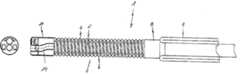
- FIG. 1shows the front portion of an endoscope shaft including its movable distal end in accordance with a first preferred embodiment of the invention.
- FIG. 2Ashows the movable distal end according to FIG. 1 in an enlarged illustration.
- FIG. 2Bshows a movable distal end in accordance with a second preferred embodiment of the invention.
- FIG. 2Cshows a movable distal end in accordance with a third preferred embodiment of the invention.
- FIG. 3Ashows a shaft head in a top view including the movable end portion according to the first preferred embodiment, wherein the shaft head can also be placed upon the movable end portion according to the second or third embodiment.
- FIG. 3Bshows a shaft head in a side view including the movable end portion according to the first preferred embodiment, wherein the shaft head can also be placed upon the movable end portion according to the second or third embodiment.
- FIGS. 4A to 4 Cshow the motion behavior of the distal end according to the invention when pressure is applied.
- FIG. 5shows an operating device of the distal end according to the invention.
- the endoscope shaft 1 in accordance with the first preferred embodiment of the inventionhas a movable distal end portion 2 adapted to be bent by means of an operating device 3 as it will be described hereinafter by way of FIG. 5 as a possible embodiment which can also be designed differently, however.
- the distal end portion 2includes at least one (four in the present case) decentralized hose member 4 - 7 extending along the distal end portion which is integrally formed of a plurality of (at least two) extension bellows substantially superimposed on a straight line so as to achieve this longitudinal extension.
- This hose-like elongated expansion bellow memberforms a single, i.e. integrated pressure chamber in such a manner that the expansion bellow member substantially extends in the longitudinal direction only, whereby the movable end portion bends due to the decentralized arrangement of the at least one expansion bellow member.
- the endoscope shaft 1moreover includes a rear shaft portion 8 to the rear end of which (not shown in FIG. 1 ) the operating device 3 for the distal end portion 2 is connected and which is preferably used in a feed means 9 comprising a reversing hose system known from prior art.
- the rear shaft portion 8includes a number of working, supply and operating conduits separated from each other through which for instance hydraulic fluid for individually applying pressure to the hose members 4 - 7 , cleansing liquids, working instruments or simply cables for optical or electric means can be guided at a shaft head 10 arranged at the distal end of the end portion 2 .
- the movable distal end portion 2is fixedly connected to the front end of the rear shaft portion 8 in such a manner that the conduits formed in the rear shaft portion 8 open into corresponding conduits inside the distal end portion 2 in a fluid-tight manner.
- the distal end portion 2 hereforis non-detachably welded to the rear shaft portion 8 , wherein also a detachable plug-in or screw-in connection is possible, of course.
- the shaft head 10is connected to the front end of the distal end portion 2 , especially in the same way as the distal end portion 2 is to the rear shaft portion 8 .
- the shaft head 10consists of a housing 11 closed at least at the front face in which a board 12 aligned at a parallel distance from the housing face is inserted.
- a photocell or a camera chip 13as well as lighting bodies are mounted which sealingly project through corresponding openings at the housing front.
- a central working conduit 14which is likewise guided through the board 12 and opens into an aperture at the housing front is laid in the housing 11 .
- the working conduit 14further supply conduits, for instance for supplying cleansing liquid or air, are provided.
- FIG. 2A to 2 Cdifferent embodiments of the distal bendable end portion 2 are illustrated both in a lateral view and in cross-sectional view.
- the movable distal end portion 2comprises four hose members 4 , 5 , 6 , 7 , each of which has the shape of a quarter circle in cross-section.
- Each hose member 4 - 7consists of a hose-like hollow of an as non-extensible as possible but flexible material, such as a reinforced synthetic material the wall thickness of which is greater in the outer partial circle portion than at the two straight flank portions.
- each hose member 4 - 7is formed in the cross-sectional view as an internal partial circle which, when all four hose members 4 - 7 are assembled, encloses a central inner conduit 15 connected to the corresponding working conduit 14 in the shaft head 10 and to the working conduit in the rear shaft portion 8 .
- each hose member 4 - 7has a plurality of radially projecting protuberances which are arranged obliquely with respect to the longitudinal axis of the hose member 4 - 7 .
- this outer supporting corsetis formed of a helical spring 17 the gradient and dimension of which is adapted to the outer helical shape of the distal end portion 2 and which is inserted between the radially projecting protuberances 16 , i.e. into the valleys of the helical shape.
- the helical spring wireis preferably designed such (for instance so as to be rectangular or oval) that it permits an as unforced bending of the spring 17 as possible, but develops a high resistance to a radial expansion of the spring 17 .
- the spring 17furthermore exerts an inwardly directed radial force on the hose members 4 - 7 to keep them in their relative position.
- FIG. 2Ba second preferred embodiment is shown for the movable distal end portion 2 according to the invention, wherein identical reference numerals are used for parts which are equal to the first embodiment.
- the supporting corsetis made of an elastic hose-like envelope 18 which is pulled over the assembled hose members 4 - 7 under a predetermined prestress so as to hereby exert a radially inwardly directed force on the hose members 4 - 7 .
- the envelope 18may be shrunk onto the hose members 4 - 7 or glued to the same.
- the expansion bellow structure of each hose segment 4 - 7 according to the second embodimentis different from that of the first embodiment. Since the helical spring 17 is replaced by the hose envelope 18 , a helical expansion bellow structure according to FIG.
- each hose member 4 - 7is formed as radial ring segments spaced apart in parallel which are completed in the assembled state of the four hose members 4 - 7 to form circumferential closed rings.
- individual metallic or synthetic collarsmay be inserted in the valleys between the protuberances 16 which contribute to preventing the hose members 4 - 7 from radially widening when pressure is applied.
- FIG. 2Ca third preferred embodiment for a distal end portion according to the invention is illustrated, wherein also in this case identical reference numerals are used for components already described before.
- the hose members 4 - 7are designed as in the second embodiment, they may also be designed, however, as in the first embodiment, i.e. having helical protuberances 16 .
- longitudinally extending continuous notches 19are formed at the hose elements 4 - 7 in the form of quarter circle segments as a result of rounded edges due to manufacture. These notches 19 can be utilized as recess of a supporting corset according to the invention.
- the longitudinally extending notches 19are filled with a glue 20 , the notches on the one hand causing, after binding the glue, an outside gluing of the adjacent hose members 4 - 7 and, on the other hand, serving as reinforcing ropes.
- This form of a supporting corsetcan already be realized upon assembling the hose segments 4 - 7 without the dimensions of the distal end portion 2 enlarging in the radial direction.
- these gluingsare not only suited as a sole measure for reducing radial widenings due to the application of pressure but especially as a supplementation of the technical measure as described already by way of FIGS. 2A and 2B .
- the operating means 3 for the hose members 4 - 7 of the distal end portion 2is represented by way of example. Accordingly, it comprises four piston/cylinder or, as an alternative, two double piston/cylinder arrangements 21 which are connected to each other by operating rods 22 .
- Each cylinder, or in the case of the (double-lift) doublethrust double piston cylinderseach cylinder side is hydraulically connected to one of the hose segments 4 - 7 through the operating conduits inside the endoscope shaft so that upon operation of one cylinder (cylinder side) for applying pressure to a hose member at the same time another cylinder (cylinder side) is operated for appropriately reducing the pressure on the respectively diametrical hose member.
- at least one hose memberis extended in the longitudinal direction while the diametrical hose member is shortened in the longitudinal direction, thereby a bend-off of the distal end portion 2 being effected in the direction of the shortening hose member.
- the endoscopecan be manually rotated as a whole inside a hollow to be examined. Hence in this case it is not necessary to design the movable distal end portion to be bendable in all directions. It is rather sufficient to permit a bend-off in one direction only (two-dimensionally). This can be obtained already by only one or two of the decentralized hose members which in this case need not have the shape of a quarter circle but may have any other cross-sectional shape. By this measure not only the constructional effort of the entire endoscope shaft is reduced but also an additional hollow is provided for further or larger operating and supply conduits.
- the envelope-shaped hose 18 shown in FIG. 2Bcan be provided with a reinforcement so that the latter prevents the envelope 18 from radially expanding, but leaves the elasticity of the envelope material in the longitudinal direction largely unaffected.
- hose membersform a substantially straight, longitudinally extending hollow
- FIG. 4A to 4 C and 5Concerning the description of the functioning FIG. 4A to 4 C and 5 are referred to.
- the piston/cylinder units 21 connected theretoare correspondingly operated, whereby hydraulic fluid is guided through hydraulic lines 23 and the hydraulic conduits inside the endoscope shaft 1 to the hose members 4 - 7 or is discharged from the same.
- a pressureis built up hereby in at least one of the hose members 4 - 7 , the same is expanded in the longitudinal direction, whereas the diametrical hose member is shortened in the longitudinal direction by a discharge of the hydraulic fluid.
- the outer supporting corset according to the inventionprevents or reduces a radial swelling of the hose members 4 - 7 so that the volume flow of hydraulic fluid is substantially converted only into a longitudinal expansion of the respective hose member.
Landscapes
- Health & Medical Sciences (AREA)
- Life Sciences & Earth Sciences (AREA)
- Engineering & Computer Science (AREA)
- Physics & Mathematics (AREA)
- Surgery (AREA)
- Biophysics (AREA)
- Veterinary Medicine (AREA)
- Public Health (AREA)
- General Health & Medical Sciences (AREA)
- Animal Behavior & Ethology (AREA)
- Biomedical Technology (AREA)
- Heart & Thoracic Surgery (AREA)
- Medical Informatics (AREA)
- Mechanical Engineering (AREA)
- Radiology & Medical Imaging (AREA)
- Pathology (AREA)
- Optics & Photonics (AREA)
- Nuclear Medicine, Radiotherapy & Molecular Imaging (AREA)
- Fluid Mechanics (AREA)
- Molecular Biology (AREA)
- General Engineering & Computer Science (AREA)
- Pulmonology (AREA)
- Anesthesiology (AREA)
- Hematology (AREA)
- Endoscopes (AREA)
- Instruments For Viewing The Inside Of Hollow Bodies (AREA)
Abstract
Description
Claims (26)
Applications Claiming Priority (2)
| Application Number | Priority Date | Filing Date | Title |
|---|---|---|---|
| DE10209986ADE10209986B4 (en) | 2002-03-07 | 2002-03-07 | Endoscope shaft with a movable end section |
| DE10290986.3 | 2002-03-07 |
Publications (2)
| Publication Number | Publication Date |
|---|---|
| US20030181785A1 US20030181785A1 (en) | 2003-09-25 |
| US6899674B2true US6899674B2 (en) | 2005-05-31 |
Family
ID=27740673
Family Applications (1)
| Application Number | Title | Priority Date | Filing Date |
|---|---|---|---|
| US10/368,734Expired - LifetimeUS6899674B2 (en) | 2002-03-07 | 2003-02-19 | Endoscope shaft comprising a movable end portion |
Country Status (6)
| Country | Link |
|---|---|
| US (1) | US6899674B2 (en) |
| EP (1) | EP1342446B1 (en) |
| JP (1) | JP4044463B2 (en) |
| AT (1) | ATE343345T1 (en) |
| DE (2) | DE10209986B4 (en) |
| ES (1) | ES2279019T3 (en) |
Cited By (65)
| Publication number | Priority date | Publication date | Assignee | Title |
|---|---|---|---|---|
| US20060206002A1 (en)* | 2005-02-28 | 2006-09-14 | Frassica James J | Rotate-to-advance catheterization system |
| US20070055102A1 (en)* | 2005-09-02 | 2007-03-08 | Yasuo Hirata | Endoscope apparatus |
| US7241263B2 (en) | 2004-09-30 | 2007-07-10 | Scimed Life Systems, Inc. | Selectively rotatable shaft coupler |
| US20070198058A1 (en)* | 2006-02-21 | 2007-08-23 | Daniel Gelbart | Method and device for closing holes in tissue |
| US20070282304A1 (en)* | 2006-06-02 | 2007-12-06 | Fujinon Sano Corporation And Fujinon Corporation | Flexible channel for use on endoscope |
| US20080004697A1 (en)* | 2006-06-28 | 2008-01-03 | Samuel Victor Lichtenstein | Method for anchoring a mitral valve |
| US20080004534A1 (en)* | 2006-06-28 | 2008-01-03 | Daniel Gelbart | Intra-cardiac mapping and ablation method |
| US20080009673A1 (en)* | 2006-05-15 | 2008-01-10 | Khachi Gerald J | Balloon endoscope device |
| US20080045778A1 (en)* | 2006-08-02 | 2008-02-21 | Samuel Victor Lichtenstein | System for improving diastolic dysfunction |
| US7413543B2 (en) | 2003-04-01 | 2008-08-19 | Scimed Life Systems, Inc. | Endoscope with actively cooled illumination sources |
| US7479106B2 (en) | 2004-09-30 | 2009-01-20 | Boston Scientific Scimed, Inc. | Automated control of irrigation and aspiration in a single-use endoscope |
| US20090076597A1 (en)* | 2007-09-19 | 2009-03-19 | Jonathan Micheal Dahlgren | System for mechanical adjustment of medical implants |
| US20090158539A1 (en)* | 2007-12-21 | 2009-06-25 | Olympus Medical Systems Corp. | Endoscope washing and disinfecting apparatus and leak detection method performed by the apparatus |
| US7578786B2 (en) | 2003-04-01 | 2009-08-25 | Boston Scientific Scimed, Inc. | Video endoscope |
| US7591783B2 (en) | 2003-04-01 | 2009-09-22 | Boston Scientific Scimed, Inc. | Articulation joint for video endoscope |
| US7597662B2 (en) | 2004-09-30 | 2009-10-06 | Boston Scientific Scimed, Inc. | Multi-fluid delivery system |
| US20090287304A1 (en)* | 2008-05-13 | 2009-11-19 | Kardium Inc. | Medical Device for Constricting Tissue or a Bodily Orifice, for example a mitral valve |
| US7846107B2 (en) | 2005-05-13 | 2010-12-07 | Boston Scientific Scimed, Inc. | Endoscopic apparatus with integrated multiple biopsy device |
| US7955255B2 (en) | 2006-04-20 | 2011-06-07 | Boston Scientific Scimed, Inc. | Imaging assembly with transparent distal cap |
| US7967759B2 (en) | 2006-01-19 | 2011-06-28 | Boston Scientific Scimed, Inc. | Endoscopic system with integrated patient respiratory status indicator |
| US20110178370A1 (en)* | 1997-02-10 | 2011-07-21 | Frassica James J | Rotate to advance catheterization system |
| US8052597B2 (en) | 2005-08-30 | 2011-11-08 | Boston Scientific Scimed, Inc. | Method for forming an endoscope articulation joint |
| US8083671B2 (en) | 2004-09-30 | 2011-12-27 | Boston Scientific Scimed, Inc. | Fluid delivery system for use with an endoscope |
| US8097003B2 (en) | 2005-05-13 | 2012-01-17 | Boston Scientific Scimed, Inc. | Endoscopic apparatus with integrated variceal ligation device |
| US8118732B2 (en) | 2003-04-01 | 2012-02-21 | Boston Scientific Scimed, Inc. | Force feedback control system for video endoscope |
| US8150499B2 (en) | 2006-05-19 | 2012-04-03 | Kardium Inc. | Automatic atherectomy system |
| US8199187B2 (en) | 2004-09-30 | 2012-06-12 | Boston Scientific Scimed, Inc. | Adapter for use with digital imaging medical device |
| US8202265B2 (en) | 2006-04-20 | 2012-06-19 | Boston Scientific Scimed, Inc. | Multiple lumen assembly for use in endoscopes or other medical devices |
| US8235942B2 (en) | 2005-05-04 | 2012-08-07 | Olympus Endo Technology America Inc. | Rotate-to-advance catheterization system |
| US8317678B2 (en) | 2005-05-04 | 2012-11-27 | Olympus Endo Technology America Inc. | Rotate-to-advance catheterization system |
| US8343040B2 (en) | 2005-05-04 | 2013-01-01 | Olympus Endo Technology America Inc. | Rotate-to-advance catheterization system |
| US8353860B2 (en) | 2004-09-30 | 2013-01-15 | Boston Scientific Scimed, Inc. | Device for obstruction removal with specific tip structure |
| US8357148B2 (en) | 2004-09-30 | 2013-01-22 | Boston Scientific Scimed, Inc. | Multi-functional endoscopic system for use in electrosurgical applications |
| US8366674B2 (en) | 2005-05-04 | 2013-02-05 | Olympus Endo Technology America Inc. | Rotate-to-advance catheterization system |
| US8414477B2 (en) | 2005-05-04 | 2013-04-09 | Olympus Endo Technology America Inc. | Rotate-to-advance catheterization system |
| US8435229B2 (en) | 2006-02-28 | 2013-05-07 | Olympus Endo Technology America Inc. | Rotate-to-advance catheterization system |
| US8489172B2 (en) | 2008-01-25 | 2013-07-16 | Kardium Inc. | Liposuction system |
| US8535219B2 (en) | 2003-04-01 | 2013-09-17 | Boston Scientific Scimed, Inc. | Fluid manifold for endoscope system |
| US8574220B2 (en) | 2006-02-28 | 2013-11-05 | Olympus Endo Technology America Inc. | Rotate-to-advance catheterization system |
| US8777841B2 (en) | 2007-05-18 | 2014-07-15 | Olympus Endo Technology America Inc. | Rotate-to-advance catheterization system |
| US8888684B2 (en) | 2006-03-27 | 2014-11-18 | Boston Scientific Scimed, Inc. | Medical devices with local drug delivery capabilities |
| US8906011B2 (en) | 2007-11-16 | 2014-12-09 | Kardium Inc. | Medical device for use in bodily lumens, for example an atrium |
| US8940002B2 (en) | 2010-09-30 | 2015-01-27 | Kardium Inc. | Tissue anchor system |
| US9005151B2 (en) | 2011-09-07 | 2015-04-14 | Choon Kee Lee | Thermal apparatus |
| US9011423B2 (en) | 2012-05-21 | 2015-04-21 | Kardium, Inc. | Systems and methods for selecting, activating, or selecting and activating transducers |
| US9050066B2 (en) | 2010-06-07 | 2015-06-09 | Kardium Inc. | Closing openings in anatomical tissue |
| US9072511B2 (en) | 2011-03-25 | 2015-07-07 | Kardium Inc. | Medical kit for constricting tissue or a bodily orifice, for example, a mitral valve |
| US9119633B2 (en) | 2006-06-28 | 2015-09-01 | Kardium Inc. | Apparatus and method for intra-cardiac mapping and ablation |
| US9186049B2 (en) | 2012-10-25 | 2015-11-17 | Choon Kee Lee | Extensible and guidable apparatus |
| US9198592B2 (en) | 2012-05-21 | 2015-12-01 | Kardium Inc. | Systems and methods for activating transducers |
| US9204964B2 (en) | 2009-10-01 | 2015-12-08 | Kardium Inc. | Medical device, kit and method for constricting tissue or a bodily orifice, for example, a mitral valve |
| US9220395B2 (en) | 1999-09-27 | 2015-12-29 | James J. Frassica | Rotate-to-advance catheterization system |
| US9452016B2 (en) | 2011-01-21 | 2016-09-27 | Kardium Inc. | Catheter system |
| US9480525B2 (en) | 2011-01-21 | 2016-11-01 | Kardium, Inc. | High-density electrode-based medical device system |
| US9492228B2 (en) | 2011-01-21 | 2016-11-15 | Kardium Inc. | Enhanced medical device for use in bodily cavities, for example an atrium |
| USD777925S1 (en) | 2012-01-20 | 2017-01-31 | Kardium Inc. | Intra-cardiac procedure device |
| USD777926S1 (en) | 2012-01-20 | 2017-01-31 | Kardium Inc. | Intra-cardiac procedure device |
| US20170112358A1 (en)* | 2014-04-10 | 2017-04-27 | Sharp Kabushiki Kaisha | Bending device, control device, and medical instrument |
| US20170196436A1 (en)* | 2014-05-30 | 2017-07-13 | Sharp Kabushiki Kaisha | Bending device, control device, and medical instrument |
| US10028783B2 (en) | 2006-06-28 | 2018-07-24 | Kardium Inc. | Apparatus and method for intra-cardiac mapping and ablation |
| US10368936B2 (en) | 2014-11-17 | 2019-08-06 | Kardium Inc. | Systems and methods for selecting, activating, or selecting and activating transducers |
| US10722184B2 (en) | 2014-11-17 | 2020-07-28 | Kardium Inc. | Systems and methods for selecting, activating, or selecting and activating transducers |
| US10827977B2 (en) | 2012-05-21 | 2020-11-10 | Kardium Inc. | Systems and methods for activating transducers |
| US11259867B2 (en) | 2011-01-21 | 2022-03-01 | Kardium Inc. | High-density electrode-based medical device system |
| US11389232B2 (en) | 2006-06-28 | 2022-07-19 | Kardium Inc. | Apparatus and method for intra-cardiac mapping and ablation |
Families Citing this family (34)
| Publication number | Priority date | Publication date | Assignee | Title |
|---|---|---|---|---|
| DE102004052036A1 (en) | 2004-10-26 | 2006-04-27 | Stm Medizintechnik Starnberg Gmbh | Endoscope for examining channel-like cavity e.g. duodenum, has alternating propulsion system to propel endoscope shaft into cavity using auxiliary unit e.g. flexible tube with fluid pad, or guided wire |
| DE102004058929A1 (en)* | 2004-12-07 | 2006-06-08 | Stm Medizintechnik Starnberg Gmbh | Endoscope with rotatable distal endoscope head e.g. for endoscope, has head which is connected by bendable end piece with endoscope shank to tubular construction unit |
| EP1795115B1 (en) | 2005-12-12 | 2016-04-13 | Invendo Medical GmbH | Endoscope having guiding means with variable stiffness |
| US8211114B2 (en)* | 2006-04-24 | 2012-07-03 | Ethicon Endo-Surgery, Inc. | Medical instrument having a medical snare |
| US20070250012A1 (en)* | 2006-04-24 | 2007-10-25 | Ifung Lu | Medical instrument having a medical needle-knife |
| US20070249908A1 (en)* | 2006-04-24 | 2007-10-25 | Ifung Lu | Medical cannula and medical cannula system |
| US9138250B2 (en) | 2006-04-24 | 2015-09-22 | Ethicon Endo-Surgery, Inc. | Medical instrument handle and medical instrument having a handle |
| US7837620B2 (en) | 2006-04-25 | 2010-11-23 | Ethicon Endo-Surgery, Inc. | Medical tubular assembly |
| US7927327B2 (en) | 2006-04-25 | 2011-04-19 | Ethicon Endo-Surgery, Inc. | Medical instrument having an articulatable end effector |
| US20070255312A1 (en)* | 2006-05-01 | 2007-11-01 | Ifung Lu | Medical instrument having an end-effector-associated member |
| US7758593B2 (en) | 2006-05-04 | 2010-07-20 | Ethicon Endo-Surgery, Inc. | Medical instrument handle and medical instrument having same |
| US7597661B2 (en)* | 2006-05-11 | 2009-10-06 | Ethicon Endo-Surgery, Inc. | Medical instrument having a catheter and method for using a catheter |
| US7959642B2 (en)* | 2006-05-16 | 2011-06-14 | Ethicon Endo-Surgery, Inc. | Medical instrument having a needle knife |
| US7892166B2 (en) | 2006-05-18 | 2011-02-22 | Ethicon Endo-Surgery, Inc. | Medical instrument including a catheter having a catheter stiffener and method for using |
| US12082781B2 (en)* | 2007-01-30 | 2024-09-10 | Loma Vista Medical, Inc. | Biological navigation device |
| WO2008095052A2 (en)* | 2007-01-30 | 2008-08-07 | Loma Vista Medical, Inc., | Biological navigation device |
| DE102008009919A1 (en)* | 2008-02-15 | 2009-08-27 | Fraunhofer-Gesellschaft zur Förderung der angewandten Forschung e.V. | Instrument for insertion into inaccessible spaces |
| WO2009141810A2 (en)* | 2008-05-23 | 2009-11-26 | Oscillon Ltd | Method and device for recanalization of total occlusions |
| TWI451855B (en)* | 2008-06-25 | 2014-09-11 | Medical Intubation Tech Corp | Endoscopic swing device |
| US20110090331A1 (en)* | 2009-10-15 | 2011-04-21 | Perceptron, Inc. | Articulating imager for video borescope |
| DE102010011926A1 (en)* | 2010-03-18 | 2011-09-22 | Olympus Winter & Ibe Gmbh | Laparoscopic needle holder |
| EP3372143B1 (en)* | 2011-10-21 | 2020-09-02 | Viking Systems, Inc. | Steerable electronic stereoscopic endoscope |
| US9913570B2 (en)* | 2015-08-07 | 2018-03-13 | Enlightenvue Llc | Endoscope with variable profile tip |
| CN106539552B (en)* | 2015-09-22 | 2018-05-01 | 邝胜 | Controlled deflection structure |
| CN106139383A (en)* | 2016-07-30 | 2016-11-23 | 张燕 | Pipeline connecting flexible pipe spring loop liftex |
| EP3576596A4 (en)* | 2016-12-02 | 2021-01-06 | Vanderbilt University | STEERABLE ENDOSCOPE WITH CONTINUOUS MANIPULATOR |
| DE102017107978B4 (en) | 2017-04-12 | 2019-01-10 | Konstantin Bob | Endoscope head with swiveling camera and working channel unit |
| CA3075487A1 (en) | 2017-06-30 | 2019-01-03 | Enlightenvue Llc | Endoscopy systems and methods of use thereof |
| US10967504B2 (en) | 2017-09-13 | 2021-04-06 | Vanderbilt University | Continuum robots with multi-scale motion through equilibrium modulation |
| GB2578276A (en)* | 2018-07-30 | 2020-05-06 | Imperial College Sci Tech & Medicine | Manipulator |
| US10687698B2 (en) | 2018-09-12 | 2020-06-23 | Enlightenvue Llc | Direct endoluminal- and/or endovascular-illumination systems and methods of use thereof |
| WO2020059643A1 (en)* | 2018-09-20 | 2020-03-26 | 富士フイルム株式会社 | Endoscope tube and endoscope |
| CN113599662B (en)* | 2021-07-09 | 2023-03-21 | 张明泽 | Drainage tube convenient to lay under peritoneoscope |
| DE102022117389A1 (en) | 2022-07-12 | 2024-01-18 | Andreas Karguth | Microrobotic unit for locomotion and positioning in organic cavities |
Citations (5)
| Publication number | Priority date | Publication date | Assignee | Title |
|---|---|---|---|---|
| US4890602A (en)* | 1987-11-25 | 1990-01-02 | Hake Lawrence W | Endoscope construction with means for controlling rigidity and curvature of flexible endoscope tube |
| DE4435644A1 (en) | 1993-10-05 | 1995-04-06 | Asahi Optical Co Ltd | Bending section for an endoscope |
| DE10010932A1 (en) | 2000-03-06 | 2001-09-13 | Stm Medtech Starnberg | Endoscope probe shaft for intestinal examination has orthogonal bellows stack is easy to move to accurate position |
| WO2001080935A1 (en) | 2000-04-21 | 2001-11-01 | Universite Pierre Et Marie Curie (Paris Vi) | Device for positioning, exploring and/or operating in particular in the field of endoscopy and/or minimally invasive surgery |
| US6503194B2 (en) | 1998-06-11 | 2003-01-07 | Fritz Pauker | Endoscope shaft comprising a movable distal end |
Family Cites Families (3)
| Publication number | Priority date | Publication date | Assignee | Title |
|---|---|---|---|---|
| US4976191A (en)* | 1988-10-17 | 1990-12-11 | Kabushiki Kaisha Toshiba | Elastically deformable fluid actuator |
| CN1052916C (en)* | 1990-11-30 | 2000-05-31 | 黎浩钧 | Medical flexible parts and related method and apparatus for controlling curvity |
| US5662587A (en)* | 1992-09-16 | 1997-09-02 | Cedars Sinai Medical Center | Robotic endoscopy |
- 2002
- 2002-03-07DEDE10209986Apatent/DE10209986B4/ennot_activeExpired - Lifetime
- 2003
- 2003-02-19USUS10/368,734patent/US6899674B2/ennot_activeExpired - Lifetime
- 2003-03-05JPJP2003058737Apatent/JP4044463B2/ennot_activeExpired - Fee Related
- 2003-03-06ESES03005058Tpatent/ES2279019T3/ennot_activeExpired - Lifetime
- 2003-03-06EPEP03005058Apatent/EP1342446B1/ennot_activeExpired - Lifetime
- 2003-03-06ATAT03005058Tpatent/ATE343345T1/ennot_activeIP Right Cessation
- 2003-03-06DEDE50305456Tpatent/DE50305456D1/ennot_activeExpired - Lifetime
Patent Citations (7)
| Publication number | Priority date | Publication date | Assignee | Title |
|---|---|---|---|---|
| US4890602A (en)* | 1987-11-25 | 1990-01-02 | Hake Lawrence W | Endoscope construction with means for controlling rigidity and curvature of flexible endoscope tube |
| DE4435644A1 (en) | 1993-10-05 | 1995-04-06 | Asahi Optical Co Ltd | Bending section for an endoscope |
| US5577992A (en) | 1993-10-05 | 1996-11-26 | Asahi Kogaku Kogyo Kabushiki Kaisha | Bendable portion of endoscope |
| US5860914A (en)* | 1993-10-05 | 1999-01-19 | Asahi Kogaku Kogyo Kabushiki Kaisha | Bendable portion of endoscope |
| US6503194B2 (en) | 1998-06-11 | 2003-01-07 | Fritz Pauker | Endoscope shaft comprising a movable distal end |
| DE10010932A1 (en) | 2000-03-06 | 2001-09-13 | Stm Medtech Starnberg | Endoscope probe shaft for intestinal examination has orthogonal bellows stack is easy to move to accurate position |
| WO2001080935A1 (en) | 2000-04-21 | 2001-11-01 | Universite Pierre Et Marie Curie (Paris Vi) | Device for positioning, exploring and/or operating in particular in the field of endoscopy and/or minimally invasive surgery |
Cited By (182)
| Publication number | Priority date | Publication date | Assignee | Title |
|---|---|---|---|---|
| US8764631B2 (en) | 1997-02-10 | 2014-07-01 | Olympus Endo Technology America Inc. | Rotate to advance catheterization system |
| US20110178370A1 (en)* | 1997-02-10 | 2011-07-21 | Frassica James J | Rotate to advance catheterization system |
| US9220395B2 (en) | 1999-09-27 | 2015-12-29 | James J. Frassica | Rotate-to-advance catheterization system |
| US7578786B2 (en) | 2003-04-01 | 2009-08-25 | Boston Scientific Scimed, Inc. | Video endoscope |
| US8425408B2 (en) | 2003-04-01 | 2013-04-23 | Boston Scientific Scimed, Inc. | Articulation joint for video endoscope |
| US8622894B2 (en) | 2003-04-01 | 2014-01-07 | Boston Scientific Scimed, Inc. | Articulation joint |
| US9913573B2 (en) | 2003-04-01 | 2018-03-13 | Boston Scientific Scimed, Inc. | Endoscopic imaging system |
| US8475366B2 (en) | 2003-04-01 | 2013-07-02 | Boston Scientific Scimed, Inc. | Articulation joint for a medical device |
| US8118732B2 (en) | 2003-04-01 | 2012-02-21 | Boston Scientific Scimed, Inc. | Force feedback control system for video endoscope |
| US7413543B2 (en) | 2003-04-01 | 2008-08-19 | Scimed Life Systems, Inc. | Endoscope with actively cooled illumination sources |
| US8608648B2 (en) | 2003-04-01 | 2013-12-17 | Boston Scientific Scimed, Inc. | Articulation joint |
| US10765307B2 (en) | 2003-04-01 | 2020-09-08 | Boston Scientific Scimed, Inc. | Endoscopic imaging system |
| US11324395B2 (en) | 2003-04-01 | 2022-05-10 | Boston Scientific Scimed, Inc. | Endoscopic imaging system |
| US8535219B2 (en) | 2003-04-01 | 2013-09-17 | Boston Scientific Scimed, Inc. | Fluid manifold for endoscope system |
| US7591783B2 (en) | 2003-04-01 | 2009-09-22 | Boston Scientific Scimed, Inc. | Articulation joint for video endoscope |
| US8353860B2 (en) | 2004-09-30 | 2013-01-15 | Boston Scientific Scimed, Inc. | Device for obstruction removal with specific tip structure |
| US8083671B2 (en) | 2004-09-30 | 2011-12-27 | Boston Scientific Scimed, Inc. | Fluid delivery system for use with an endoscope |
| US8199187B2 (en) | 2004-09-30 | 2012-06-12 | Boston Scientific Scimed, Inc. | Adapter for use with digital imaging medical device |
| US8197400B2 (en) | 2004-09-30 | 2012-06-12 | Boston Scientific Scimed, Inc. | Selectively rotatable shaft coupler |
| USRE46007E1 (en) | 2004-09-30 | 2016-05-24 | Boston Scientific Scimed, Inc. | Automated control of irrigation and aspiration in a single-use endoscope |
| US7479106B2 (en) | 2004-09-30 | 2009-01-20 | Boston Scientific Scimed, Inc. | Automated control of irrigation and aspiration in a single-use endoscope |
| US8435172B2 (en) | 2004-09-30 | 2013-05-07 | Boston Scientific Scimed, Inc. | Automated control of irrigation and aspiration in a single-use endoscope |
| US8357148B2 (en) | 2004-09-30 | 2013-01-22 | Boston Scientific Scimed, Inc. | Multi-functional endoscopic system for use in electrosurgical applications |
| US7597662B2 (en) | 2004-09-30 | 2009-10-06 | Boston Scientific Scimed, Inc. | Multi-fluid delivery system |
| US7241263B2 (en) | 2004-09-30 | 2007-07-10 | Scimed Life Systems, Inc. | Selectively rotatable shaft coupler |
| US8377041B2 (en)* | 2005-02-28 | 2013-02-19 | Olympus Endo Technology America Inc. | Rotate-to-advance catheterization system |
| US20060206002A1 (en)* | 2005-02-28 | 2006-09-14 | Frassica James J | Rotate-to-advance catheterization system |
| US8366674B2 (en) | 2005-05-04 | 2013-02-05 | Olympus Endo Technology America Inc. | Rotate-to-advance catheterization system |
| US8317678B2 (en) | 2005-05-04 | 2012-11-27 | Olympus Endo Technology America Inc. | Rotate-to-advance catheterization system |
| US8235942B2 (en) | 2005-05-04 | 2012-08-07 | Olympus Endo Technology America Inc. | Rotate-to-advance catheterization system |
| US8747300B2 (en) | 2005-05-04 | 2014-06-10 | Olympus Endo Technology America Inc. | Rotate-to-advance catheterization system |
| US8343040B2 (en) | 2005-05-04 | 2013-01-01 | Olympus Endo Technology America Inc. | Rotate-to-advance catheterization system |
| US8414477B2 (en) | 2005-05-04 | 2013-04-09 | Olympus Endo Technology America Inc. | Rotate-to-advance catheterization system |
| US7846107B2 (en) | 2005-05-13 | 2010-12-07 | Boston Scientific Scimed, Inc. | Endoscopic apparatus with integrated multiple biopsy device |
| US8097003B2 (en) | 2005-05-13 | 2012-01-17 | Boston Scientific Scimed, Inc. | Endoscopic apparatus with integrated variceal ligation device |
| US8585715B2 (en) | 2005-05-13 | 2013-11-19 | Boston Scientific Scimed, Inc. | Endoscopic apparatus with integrated variceal ligation device |
| US8052597B2 (en) | 2005-08-30 | 2011-11-08 | Boston Scientific Scimed, Inc. | Method for forming an endoscope articulation joint |
| US10052013B2 (en) | 2005-08-30 | 2018-08-21 | Boston Scientific Scimed, Inc. | Medical device comprising segments |
| US9439557B2 (en) | 2005-08-30 | 2016-09-13 | Boston Scientific Scimed, Inc. | Articulation joint |
| US11191424B2 (en) | 2005-08-30 | 2021-12-07 | Boston Scientific Scimed, Inc. | Method for forming an endoscope articulation joint |
| US11957312B2 (en) | 2005-08-30 | 2024-04-16 | Boston Scientific Scimed, Inc. | Method for forming an endoscope articulation joint |
| US20070055102A1 (en)* | 2005-09-02 | 2007-03-08 | Yasuo Hirata | Endoscope apparatus |
| US7967759B2 (en) | 2006-01-19 | 2011-06-28 | Boston Scientific Scimed, Inc. | Endoscopic system with integrated patient respiratory status indicator |
| US7749249B2 (en) | 2006-02-21 | 2010-07-06 | Kardium Inc. | Method and device for closing holes in tissue |
| US8337524B2 (en) | 2006-02-21 | 2012-12-25 | Kardium Inc. | Method and device for closing holes in tissue |
| US20100222789A1 (en)* | 2006-02-21 | 2010-09-02 | Kardium Inc. | Method and device for closing holes in tissue |
| US9572557B2 (en) | 2006-02-21 | 2017-02-21 | Kardium Inc. | Method and device for closing holes in tissue |
| US20070198058A1 (en)* | 2006-02-21 | 2007-08-23 | Daniel Gelbart | Method and device for closing holes in tissue |
| US8435229B2 (en) | 2006-02-28 | 2013-05-07 | Olympus Endo Technology America Inc. | Rotate-to-advance catheterization system |
| US8574220B2 (en) | 2006-02-28 | 2013-11-05 | Olympus Endo Technology America Inc. | Rotate-to-advance catheterization system |
| US8888684B2 (en) | 2006-03-27 | 2014-11-18 | Boston Scientific Scimed, Inc. | Medical devices with local drug delivery capabilities |
| US8870753B2 (en) | 2006-04-20 | 2014-10-28 | Boston Scientific Scimed, Inc. | Imaging assembly with transparent distal cap |
| US9358363B2 (en) | 2006-04-20 | 2016-06-07 | Boston Scientific Scimed, Inc. | Multiple lumen assembly for use in endoscopes or other medical devices |
| US8202265B2 (en) | 2006-04-20 | 2012-06-19 | Boston Scientific Scimed, Inc. | Multiple lumen assembly for use in endoscopes or other medical devices |
| US7955255B2 (en) | 2006-04-20 | 2011-06-07 | Boston Scientific Scimed, Inc. | Imaging assembly with transparent distal cap |
| US20080009673A1 (en)* | 2006-05-15 | 2008-01-10 | Khachi Gerald J | Balloon endoscope device |
| US8038598B2 (en) | 2006-05-15 | 2011-10-18 | Baystate Health, Inc. | Balloon endoscope device |
| US8532746B2 (en) | 2006-05-19 | 2013-09-10 | Kardium Inc. | Automatic atherectomy system |
| US8150499B2 (en) | 2006-05-19 | 2012-04-03 | Kardium Inc. | Automatic atherectomy system |
| US20070282304A1 (en)* | 2006-06-02 | 2007-12-06 | Fujinon Sano Corporation And Fujinon Corporation | Flexible channel for use on endoscope |
| US8663197B2 (en)* | 2006-06-02 | 2014-03-04 | Fujifilm Corporation | Flexible channel for use on endoscope |
| US9119634B2 (en) | 2006-06-28 | 2015-09-01 | Kardium Inc. | Apparatus and method for intra-cardiac mapping and ablation |
| US10828094B2 (en) | 2006-06-28 | 2020-11-10 | Kardium Inc. | Apparatus and method for intra-cardiac mapping and ablation |
| US11389231B2 (en) | 2006-06-28 | 2022-07-19 | Kardium Inc. | Apparatus and method for intra-cardiac mapping and ablation |
| US8449605B2 (en) | 2006-06-28 | 2013-05-28 | Kardium Inc. | Method for anchoring a mitral valve |
| US8920411B2 (en) | 2006-06-28 | 2014-12-30 | Kardium Inc. | Apparatus and method for intra-cardiac mapping and ablation |
| US20080004697A1 (en)* | 2006-06-28 | 2008-01-03 | Samuel Victor Lichtenstein | Method for anchoring a mitral valve |
| US20080004534A1 (en)* | 2006-06-28 | 2008-01-03 | Daniel Gelbart | Intra-cardiac mapping and ablation method |
| US10828093B2 (en) | 2006-06-28 | 2020-11-10 | Kardium Inc. | Apparatus and method for intra-cardiac mapping and ablation |
| US11399890B2 (en) | 2006-06-28 | 2022-08-02 | Kardium Inc. | Apparatus and method for intra-cardiac mapping and ablation |
| US9987084B2 (en) | 2006-06-28 | 2018-06-05 | Kardium Inc. | Apparatus and method for intra-cardiac mapping and ablation |
| US10820941B2 (en) | 2006-06-28 | 2020-11-03 | Kardium Inc. | Apparatus and method for intra-cardiac mapping and ablation |
| US11389232B2 (en) | 2006-06-28 | 2022-07-19 | Kardium Inc. | Apparatus and method for intra-cardiac mapping and ablation |
| US9987083B2 (en) | 2006-06-28 | 2018-06-05 | Kardium Inc. | Apparatus and method for intra-cardiac mapping and ablation |
| US9119633B2 (en) | 2006-06-28 | 2015-09-01 | Kardium Inc. | Apparatus and method for intra-cardiac mapping and ablation |
| US8672998B2 (en) | 2006-06-28 | 2014-03-18 | Kardium Inc. | Method for anchoring a mitral valve |
| US10028783B2 (en) | 2006-06-28 | 2018-07-24 | Kardium Inc. | Apparatus and method for intra-cardiac mapping and ablation |
| US9192468B2 (en) | 2006-06-28 | 2015-11-24 | Kardium Inc. | Method for anchoring a mitral valve |
| US11033392B2 (en) | 2006-08-02 | 2021-06-15 | Kardium Inc. | System for improving diastolic dysfunction |
| US20080045778A1 (en)* | 2006-08-02 | 2008-02-21 | Samuel Victor Lichtenstein | System for improving diastolic dysfunction |
| US7837610B2 (en) | 2006-08-02 | 2010-11-23 | Kardium Inc. | System for improving diastolic dysfunction |
| US20110087203A1 (en)* | 2006-08-02 | 2011-04-14 | Kardium Inc. | System for improving diastolic dysfunction |
| US8870755B2 (en) | 2007-05-18 | 2014-10-28 | Olympus Endo Technology America Inc. | Rotate-to-advance catheterization system |
| US8777841B2 (en) | 2007-05-18 | 2014-07-15 | Olympus Endo Technology America Inc. | Rotate-to-advance catheterization system |
| US20090076597A1 (en)* | 2007-09-19 | 2009-03-19 | Jonathan Micheal Dahlgren | System for mechanical adjustment of medical implants |
| US10828098B2 (en) | 2007-11-16 | 2020-11-10 | Kardium Inc. | Medical device for use in bodily lumens, for example an atrium |
| US9585717B2 (en) | 2007-11-16 | 2017-03-07 | Kardium Inc. | Medical device for use in bodily lumens, for example an atrium |
| US11076913B2 (en) | 2007-11-16 | 2021-08-03 | Kardium Inc. | Medical device for use in bodily lumens, for example an atrium |
| US8932287B2 (en) | 2007-11-16 | 2015-01-13 | Kardium Inc. | Medical device for use in bodily lumens, for example an atrium |
| US10828095B2 (en) | 2007-11-16 | 2020-11-10 | Kardium Inc. | Medical device for use in bodily lumens, for example an atrium |
| US10828096B2 (en) | 2007-11-16 | 2020-11-10 | Kardium Inc. | Medical device for use in bodily lumens, for example an atrium |
| US10828097B2 (en) | 2007-11-16 | 2020-11-10 | Kardium Inc. | Medical device for use in bodily lumens, for example an atrium |
| US11304751B2 (en) | 2007-11-16 | 2022-04-19 | Kardium Inc. | Medical device for use in bodily lumens, for example an atrium |
| US8906011B2 (en) | 2007-11-16 | 2014-12-09 | Kardium Inc. | Medical device for use in bodily lumens, for example an atrium |
| US11331141B2 (en) | 2007-11-16 | 2022-05-17 | Kardium Inc. | Medical device for use in bodily lumens, for example an atrium |
| US11801091B2 (en) | 2007-11-16 | 2023-10-31 | Kardium Inc. | Medical device for use in bodily lumens, for example an atrium |
| US9877779B2 (en) | 2007-11-16 | 2018-01-30 | Kardium Inc. | Medical device for use in bodily lumens, for example an atrium |
| US10499986B2 (en) | 2007-11-16 | 2019-12-10 | Kardium Inc. | Medical device for use in bodily lumens, for example an atrium |
| US11751940B2 (en) | 2007-11-16 | 2023-09-12 | Kardium Inc. | Medical device for use in bodily lumens, for example an atrium |
| US9603661B2 (en) | 2007-11-16 | 2017-03-28 | Kardium Inc. | Medical device for use in bodily lumens, for example an atrium |
| US11633231B2 (en) | 2007-11-16 | 2023-04-25 | Kardium Inc. | Medical device for use in bodily lumens, for example an atrium |
| US11413091B2 (en) | 2007-11-16 | 2022-08-16 | Kardium Inc. | Medical device for use in bodily lumens, for example an atrium |
| US9839474B2 (en) | 2007-11-16 | 2017-12-12 | Kardium Inc. | Medical device for use in bodily lumens, for example an atrium |
| US11432874B2 (en) | 2007-11-16 | 2022-09-06 | Kardium Inc. | Medical device for use in bodily lumens, for example an atrium |
| US9820810B2 (en) | 2007-11-16 | 2017-11-21 | Kardium Inc. | Medical device for use in bodily lumens, for example an atrium |
| US9750569B2 (en) | 2007-11-16 | 2017-09-05 | Kardium Inc. | Medical device for use in bodily lumens, for example an atrium |
| US20090158539A1 (en)* | 2007-12-21 | 2009-06-25 | Olympus Medical Systems Corp. | Endoscope washing and disinfecting apparatus and leak detection method performed by the apparatus |
| US8176771B2 (en)* | 2007-12-21 | 2012-05-15 | Olympus Medical Systems Corp. | Endoscope washing and disinfecting apparatus and leak detection method performed by the apparatus |
| US8489172B2 (en) | 2008-01-25 | 2013-07-16 | Kardium Inc. | Liposuction system |
| US9744038B2 (en) | 2008-05-13 | 2017-08-29 | Kardium Inc. | Medical device for constricting tissue or a bodily orifice, for example a mitral valve |
| US20090287304A1 (en)* | 2008-05-13 | 2009-11-19 | Kardium Inc. | Medical Device for Constricting Tissue or a Bodily Orifice, for example a mitral valve |
| US10687941B2 (en) | 2009-10-01 | 2020-06-23 | Kardium Inc. | Medical device, kit and method for constricting tissue or a bodily orifice, for example, a mitral valve |
| US9867703B2 (en) | 2009-10-01 | 2018-01-16 | Kardium Inc. | Medical device, kit and method for constricting tissue or a bodily orifice, for example, a mitral valve |
| US9204964B2 (en) | 2009-10-01 | 2015-12-08 | Kardium Inc. | Medical device, kit and method for constricting tissue or a bodily orifice, for example, a mitral valve |
| US10813758B2 (en) | 2009-10-01 | 2020-10-27 | Kardium Inc. | Medical device, kit and method for constricting tissue or a bodily orifice, for example, a mitral valve |
| US9918706B2 (en) | 2010-06-07 | 2018-03-20 | Kardium Inc. | Closing openings in anatomical tissue |
| US9050066B2 (en) | 2010-06-07 | 2015-06-09 | Kardium Inc. | Closing openings in anatomical tissue |
| US10603022B2 (en) | 2010-06-07 | 2020-03-31 | Kardium Inc. | Closing openings in anatomical tissue |
| US8940002B2 (en) | 2010-09-30 | 2015-01-27 | Kardium Inc. | Tissue anchor system |
| US11896295B2 (en) | 2011-01-21 | 2024-02-13 | Kardium Inc. | High-density electrode-based medical device system |
| US11298173B2 (en) | 2011-01-21 | 2022-04-12 | Kardium Inc. | Enhanced medical device for use in bodily cavities, for example an atrium |
| US12059202B2 (en) | 2011-01-21 | 2024-08-13 | Kardium Inc. | Catheter system |
| US10485608B2 (en) | 2011-01-21 | 2019-11-26 | Kardium Inc. | Catheter system |
| US11399881B2 (en) | 2011-01-21 | 2022-08-02 | Kardium Inc. | Enhanced medical device for use in bodily cavities, for example an atrium |
| US12178490B2 (en) | 2011-01-21 | 2024-12-31 | Kardium Inc. | Enhanced medical device for use in bodily cavities, for example an atrium |
| US12349955B2 (en) | 2011-01-21 | 2025-07-08 | Kardium Inc. | Enhanced medical device for use in bodily cavities, for example an atrium |
| US9452016B2 (en) | 2011-01-21 | 2016-09-27 | Kardium Inc. | Catheter system |
| US9480525B2 (en) | 2011-01-21 | 2016-11-01 | Kardium, Inc. | High-density electrode-based medical device system |
| US9486273B2 (en) | 2011-01-21 | 2016-11-08 | Kardium Inc. | High-density electrode-based medical device system |
| US11350989B2 (en) | 2011-01-21 | 2022-06-07 | Kardium Inc. | Catheter system |
| US9492228B2 (en) | 2011-01-21 | 2016-11-15 | Kardium Inc. | Enhanced medical device for use in bodily cavities, for example an atrium |
| US11596463B2 (en) | 2011-01-21 | 2023-03-07 | Kardium Inc. | Enhanced medical device for use in bodily cavities, for example an atrium |
| US11607261B2 (en) | 2011-01-21 | 2023-03-21 | Kardium Inc. | Enhanced medical device for use in bodily cavities, for example an atrium |
| US12383325B2 (en) | 2011-01-21 | 2025-08-12 | Kardium Inc. | Enhanced medical device for use in bodily cavities, for example an atrium |
| US9526573B2 (en) | 2011-01-21 | 2016-12-27 | Kardium Inc. | Enhanced medical device for use in bodily cavities, for example an atrium |
| US9675401B2 (en) | 2011-01-21 | 2017-06-13 | Kardium Inc. | Enhanced medical device for use in bodily cavities, for example an atrium |
| US11259867B2 (en) | 2011-01-21 | 2022-03-01 | Kardium Inc. | High-density electrode-based medical device system |
| US9492227B2 (en) | 2011-01-21 | 2016-11-15 | Kardium Inc. | Enhanced medical device for use in bodily cavities, for example an atrium |
| US9072511B2 (en) | 2011-03-25 | 2015-07-07 | Kardium Inc. | Medical kit for constricting tissue or a bodily orifice, for example, a mitral valve |
| US10058318B2 (en) | 2011-03-25 | 2018-08-28 | Kardium Inc. | Medical kit for constricting tissue or a bodily orifice, for example, a mitral valve |
| US9005151B2 (en) | 2011-09-07 | 2015-04-14 | Choon Kee Lee | Thermal apparatus |
| USD777925S1 (en) | 2012-01-20 | 2017-01-31 | Kardium Inc. | Intra-cardiac procedure device |
| USD777926S1 (en) | 2012-01-20 | 2017-01-31 | Kardium Inc. | Intra-cardiac procedure device |
| US9888972B2 (en) | 2012-05-21 | 2018-02-13 | Kardium Inc. | Systems and methods for selecting, activating, or selecting and activating transducers |
| US9693832B2 (en) | 2012-05-21 | 2017-07-04 | Kardium Inc. | Systems and methods for selecting, activating, or selecting and activating transducers |
| US9532831B2 (en) | 2012-05-21 | 2017-01-03 | Kardium Inc. | Systems and methods for activating transducers |
| US11154248B2 (en) | 2012-05-21 | 2021-10-26 | Kardium Inc. | Systems and methods for activating transducers |
| US10918446B2 (en) | 2012-05-21 | 2021-02-16 | Kardium Inc. | Systems and methods for selecting, activating, or selecting and activating transducers |
| US9011423B2 (en) | 2012-05-21 | 2015-04-21 | Kardium, Inc. | Systems and methods for selecting, activating, or selecting and activating transducers |
| US10827977B2 (en) | 2012-05-21 | 2020-11-10 | Kardium Inc. | Systems and methods for activating transducers |
| US9017320B2 (en) | 2012-05-21 | 2015-04-28 | Kardium, Inc. | Systems and methods for activating transducers |
| US9017321B2 (en) | 2012-05-21 | 2015-04-28 | Kardium, Inc. | Systems and methods for activating transducers |
| US12376795B2 (en) | 2012-05-21 | 2025-08-05 | Kardium Inc. | Systems and methods for activating transducers |
| US12376796B2 (en) | 2012-05-21 | 2025-08-05 | Kardium Inc. | Systems and methods for activating transducers |
| US9572509B2 (en) | 2012-05-21 | 2017-02-21 | Kardium Inc. | Systems and methods for activating transducers |
| US10568576B2 (en) | 2012-05-21 | 2020-02-25 | Kardium Inc. | Systems and methods for activating transducers |
| US12324636B2 (en) | 2012-05-21 | 2025-06-10 | Kardium Inc. | Systems and methods for selecting, activating, or selecting and activating transducers |
| US10470826B2 (en) | 2012-05-21 | 2019-11-12 | Kardium Inc. | Systems and methods for selecting, activating, or selecting and activating transducers |
| US12226172B2 (en) | 2012-05-21 | 2025-02-18 | Kardium Inc. | Systems and methods for selecting, activating, or selecting and activating transducers |
| US9439713B2 (en) | 2012-05-21 | 2016-09-13 | Kardium Inc. | Systems and methods for activating transducers |
| US11589821B2 (en) | 2012-05-21 | 2023-02-28 | Kardium Inc. | Systems and methods for activating transducers |
| US11805974B2 (en) | 2012-05-21 | 2023-11-07 | Kardium Inc. | Systems and methods for selecting, activating, or selecting and activating transducers |
| US9198592B2 (en) | 2012-05-21 | 2015-12-01 | Kardium Inc. | Systems and methods for activating transducers |
| US11633238B2 (en) | 2012-05-21 | 2023-04-25 | Kardium Inc. | Systems and methods for selecting, activating, or selecting and activating transducers |
| US9980679B2 (en) | 2012-05-21 | 2018-05-29 | Kardium Inc. | Systems and methods for activating transducers |
| US11672485B2 (en) | 2012-05-21 | 2023-06-13 | Kardium Inc. | Systems and methods for activating transducers |
| US11690684B2 (en) | 2012-05-21 | 2023-07-04 | Kardium Inc. | Systems and methods for selecting, activating, or selecting and activating transducers |
| US9259264B2 (en) | 2012-05-21 | 2016-02-16 | Kardium Inc. | Systems and methods for activating transducers |
| US9445862B2 (en) | 2012-05-21 | 2016-09-20 | Kardium Inc. | Systems and methods for selecting, activating, or selecting and activating transducers |
| US9186049B2 (en) | 2012-10-25 | 2015-11-17 | Choon Kee Lee | Extensible and guidable apparatus |
| US10292572B2 (en)* | 2014-04-10 | 2019-05-21 | Sharp Kabushiki Kaisha | Bending device, control device, and medical instrument |
| US20170112358A1 (en)* | 2014-04-10 | 2017-04-27 | Sharp Kabushiki Kaisha | Bending device, control device, and medical instrument |
| US20170196436A1 (en)* | 2014-05-30 | 2017-07-13 | Sharp Kabushiki Kaisha | Bending device, control device, and medical instrument |
| US10492669B2 (en)* | 2014-05-30 | 2019-12-03 | Sharp Kabushiki Kaisha | Bending device, control device, and medical instrument |
| US10368936B2 (en) | 2014-11-17 | 2019-08-06 | Kardium Inc. | Systems and methods for selecting, activating, or selecting and activating transducers |
| US12133745B2 (en) | 2014-11-17 | 2024-11-05 | Kardium Inc. | Systems and methods for selecting, activating, or selecting and activating transducers |
| US11026637B2 (en) | 2014-11-17 | 2021-06-08 | Kardium Inc. | Systems and methods for selecting, activating, or selecting and activating transducers |
| US10722184B2 (en) | 2014-11-17 | 2020-07-28 | Kardium Inc. | Systems and methods for selecting, activating, or selecting and activating transducers |
| US10751006B2 (en) | 2014-11-17 | 2020-08-25 | Kardium Inc. | Systems and methods for selecting, activating, or selecting and activating transducers |
| US10758191B2 (en) | 2014-11-17 | 2020-09-01 | Kardium Inc. | Systems and methods for selecting, activating, or selecting and activating transducers |
| US12383208B2 (en) | 2014-11-17 | 2025-08-12 | Kardium Inc. | Systems and methods for selecting, activating, or selecting and activating transducers |
| US11026638B2 (en) | 2014-11-17 | 2021-06-08 | Kardium Inc. | Systems and methods for selecting, activating, or selecting and activating transducers |
Also Published As
| Publication number | Publication date |
|---|---|
| EP1342446A3 (en) | 2003-10-01 |
| DE10209986B4 (en) | 2004-07-29 |
| JP4044463B2 (en) | 2008-02-06 |
| EP1342446B1 (en) | 2006-10-25 |
| DE50305456D1 (en) | 2006-12-07 |
| JP2003275166A (en) | 2003-09-30 |
| DE10209986A1 (en) | 2003-10-02 |
| ATE343345T1 (en) | 2006-11-15 |
| US20030181785A1 (en) | 2003-09-25 |
| ES2279019T3 (en) | 2007-08-16 |
| EP1342446A2 (en) | 2003-09-10 |
Similar Documents
| Publication | Publication Date | Title |
|---|---|---|
| US6899674B2 (en) | Endoscope shaft comprising a movable end portion | |
| ES2750844T3 (en) | Instrument for endoscopic applications | |
| US5337733A (en) | Tubular inserting device with variable rigidity | |
| JP3317700B2 (en) | catheter | |
| US6503194B2 (en) | Endoscope shaft comprising a movable distal end | |
| US20020055668A1 (en) | Endoscope shaft | |
| EP0422887B1 (en) | Bending device | |
| JP4962750B2 (en) | In particular a bending deformation device for endoscopy and / or minimally invasive surgical instruments | |
| JPH038436B2 (en) | ||
| CN105792725A (en) | Flexible pipe section for endoscope and endoscope | |
| ES2222944T3 (en) | ENDOSCOPE BAR. | |
| CN115191913A (en) | Bending section, insertion section, and endoscope | |
| US7798956B2 (en) | Alternating propulsion type endoscope and continuous drive type endoscope | |
| US20070135683A1 (en) | Alternating propulsion type endoscope and continuous drive type endoscope | |
| JP6685233B2 (en) | Endoscopic instrument | |
| JP6248116B2 (en) | Flexible and extendable tubular guide and method for manufacturing the same | |
| CN110420007B (en) | Insertion tube assembly for colonoscope | |
| JPH0217063A (en) | Artificial muscle actuator | |
| JP4553501B2 (en) | Endoscope shaft with movable distal end | |
| EP1795115B1 (en) | Endoscope having guiding means with variable stiffness | |
| JP2681026B2 (en) | Endoscope | |
| CN119606284A (en) | Endoscope and hydraulically driven snake for endoscope | |
| JP2007159696A (en) | Alternating propulsion type endoscope and continuous drive type endoscope |
Legal Events
| Date | Code | Title | Description |
|---|---|---|---|
| AS | Assignment | Owner name:STM MEDIZINTECHNIK STARNBERG GMBH, GERMANY Free format text:ASSIGNMENT OF ASSIGNORS INTEREST;ASSIGNORS:VIEBACH, THOMAS;PAUKER, FRITZ;REEL/FRAME:014114/0980 Effective date:20030429 | |
| STCF | Information on status: patent grant | Free format text:PATENTED CASE | |
| FPAY | Fee payment | Year of fee payment:4 | |
| FEPP | Fee payment procedure | Free format text:PAYER NUMBER DE-ASSIGNED (ORIGINAL EVENT CODE: RMPN); ENTITY STATUS OF PATENT OWNER: SMALL ENTITY Free format text:PAYOR NUMBER ASSIGNED (ORIGINAL EVENT CODE: ASPN); ENTITY STATUS OF PATENT OWNER: SMALL ENTITY | |
| FPAY | Fee payment | Year of fee payment:8 | |
| FPAY | Fee payment | Year of fee payment:12 | |
| AS | Assignment | Owner name:STM MEDIZINTECHNIK GMBH, GERMANY Free format text:CHANGE OF NAME;ASSIGNOR:STM MEDIZINTECHNIK STARNBERG GMBH;REEL/FRAME:044697/0320 Effective date:20040724 Owner name:INVENDO MEDICAL GMBH, GERMANY Free format text:CHANGE OF NAME;ASSIGNOR:STM MEDIZINTECHNIK GMBH;REEL/FRAME:044697/0875 Effective date:20060213 |