US6898911B2 - Floor strip - Google Patents
Floor stripDownload PDFInfo
- Publication number
- US6898911B2 US6898911B2US10/319,820US31982002AUS6898911B2US 6898911 B2US6898911 B2US 6898911B2US 31982002 AUS31982002 AUS 31982002AUS 6898911 B2US6898911 B2US 6898911B2
- Authority
- US
- United States
- Prior art keywords
- floor
- assembly according
- floor strip
- strip assembly
- laminate
- Prior art date
- Legal status (The legal status is an assumption and is not a legal conclusion. Google has not performed a legal analysis and makes no representation as to the accuracy of the status listed.)
- Expired - Lifetime
Links
- 239000003638chemical reducing agentSubstances0.000claimsabstractdescription54
- 239000002245particleSubstances0.000claimsabstractdescription17
- 229920005989resinPolymers0.000claimsabstractdescription17
- 239000011347resinSubstances0.000claimsabstractdescription17
- 229920001187thermosetting polymerPolymers0.000claimsabstractdescription15
- 238000005299abrasionMethods0.000claimsabstractdescription11
- 229920000877Melamine resinPolymers0.000claimsdescription7
- 239000000835fiberSubstances0.000claimsdescription7
- UFHFLCQGNIYNRP-UHFFFAOYSA-NHydrogenChemical compound[H][H]UFHFLCQGNIYNRP-UHFFFAOYSA-N0.000claimsdescription4
- VYPSYNLAJGMNEJ-UHFFFAOYSA-NSilicium dioxideChemical compoundO=[Si]=OVYPSYNLAJGMNEJ-UHFFFAOYSA-N0.000claimsdescription4
- XLYOFNOQVPJJNP-UHFFFAOYSA-NwaterSubstancesOXLYOFNOQVPJJNP-UHFFFAOYSA-N0.000claimsdescription3
- 239000003365glass fiberSubstances0.000claimsdescription2
- HBMJWWWQQXIZIP-UHFFFAOYSA-Nsilicon carbideChemical compound[Si+]#[C-]HBMJWWWQQXIZIP-UHFFFAOYSA-N0.000claimsdescription2
- 229910010271silicon carbideInorganic materials0.000claimsdescription2
- 239000000377silicon dioxideSubstances0.000claimsdescription2
- IVJISJACKSSFGE-UHFFFAOYSA-Nformaldehyde;1,3,5-triazine-2,4,6-triamineChemical compoundO=C.NC1=NC(N)=NC(N)=N1IVJISJACKSSFGE-UHFFFAOYSA-N0.000claims1
- TWNQGVIAIRXVLR-UHFFFAOYSA-Noxo(oxoalumanyloxy)alumaneChemical compoundO=[Al]O[Al]=OTWNQGVIAIRXVLR-UHFFFAOYSA-N0.000claims1
- 230000007704transitionEffects0.000abstractdescription24
- PNEYBMLMFCGWSK-UHFFFAOYSA-NAluminaChemical compound[O-2].[O-2].[O-2].[Al+3].[Al+3]PNEYBMLMFCGWSK-UHFFFAOYSA-N0.000description15
- 239000000123paperSubstances0.000description14
- 238000009408flooringMethods0.000description7
- 238000004519manufacturing processMethods0.000description7
- 239000002023woodSubstances0.000description6
- 239000003292glueSubstances0.000description4
- 230000013011matingEffects0.000description4
- 238000000034methodMethods0.000description4
- 230000001105regulatory effectEffects0.000description4
- 238000004026adhesive bondingMethods0.000description3
- 238000010438heat treatmentMethods0.000description3
- 238000003801millingMethods0.000description3
- 239000000853adhesiveSubstances0.000description2
- 230000001070adhesive effectEffects0.000description2
- 239000000969carrierSubstances0.000description2
- 239000011094fiberboardSubstances0.000description2
- 238000010030laminatingMethods0.000description2
- 239000000463materialSubstances0.000description2
- 229920002143Vulcanized fibrePolymers0.000description1
- 239000007864aqueous solutionSubstances0.000description1
- 229910003460diamondInorganic materials0.000description1
- 239000010432diamondSubstances0.000description1
- 230000010339dilationEffects0.000description1
- 239000011888foilSubstances0.000description1
- 239000011121hardwoodSubstances0.000description1
- 238000005470impregnationMethods0.000description1
- 238000003754machiningMethods0.000description1
- 239000004579marbleSubstances0.000description1
- 229910052751metalInorganic materials0.000description1
- 239000002184metalSubstances0.000description1
- 238000012986modificationMethods0.000description1
- 230000004048modificationEffects0.000description1
- 239000003973paintSubstances0.000description1
- 238000003825pressingMethods0.000description1
- 230000002265preventionEffects0.000description1
- 239000007787solidSubstances0.000description1
- 239000002904solventSubstances0.000description1
- 125000006850spacer groupChemical group0.000description1
- 239000000758substrateSubstances0.000description1
Images


Classifications
- B—PERFORMING OPERATIONS; TRANSPORTING
- B27—WORKING OR PRESERVING WOOD OR SIMILAR MATERIAL; NAILING OR STAPLING MACHINES IN GENERAL
- B27N—MANUFACTURE BY DRY PROCESSES OF ARTICLES, WITH OR WITHOUT ORGANIC BINDING AGENTS, MADE FROM PARTICLES OR FIBRES CONSISTING OF WOOD OR OTHER LIGNOCELLULOSIC OR LIKE ORGANIC MATERIAL
- B27N7/00—After-treatment, e.g. reducing swelling or shrinkage, surfacing; Protecting the edges of boards against access of humidity
- B27N7/005—Coating boards, e.g. with a finishing or decorating layer
- B—PERFORMING OPERATIONS; TRANSPORTING
- B32—LAYERED PRODUCTS
- B32B—LAYERED PRODUCTS, i.e. PRODUCTS BUILT-UP OF STRATA OF FLAT OR NON-FLAT, e.g. CELLULAR OR HONEYCOMB, FORM
- B32B3/00—Layered products comprising a layer with external or internal discontinuities or unevennesses, or a layer of non-planar shape; Layered products comprising a layer having particular features of form
- B32B3/26—Layered products comprising a layer with external or internal discontinuities or unevennesses, or a layer of non-planar shape; Layered products comprising a layer having particular features of form characterised by a particular shape of the outline of the cross-section of a continuous layer; characterised by a layer with cavities or internal voids ; characterised by an apertured layer
- B32B3/30—Layered products comprising a layer with external or internal discontinuities or unevennesses, or a layer of non-planar shape; Layered products comprising a layer having particular features of form characterised by a particular shape of the outline of the cross-section of a continuous layer; characterised by a layer with cavities or internal voids ; characterised by an apertured layer characterised by a layer formed with recesses or projections, e.g. hollows, grooves, protuberances, ribs
- B—PERFORMING OPERATIONS; TRANSPORTING
- B32—LAYERED PRODUCTS
- B32B—LAYERED PRODUCTS, i.e. PRODUCTS BUILT-UP OF STRATA OF FLAT OR NON-FLAT, e.g. CELLULAR OR HONEYCOMB, FORM
- B32B27/00—Layered products comprising a layer of synthetic resin
- B32B27/04—Layered products comprising a layer of synthetic resin as impregnant, bonding, or embedding substance
- B—PERFORMING OPERATIONS; TRANSPORTING
- B32—LAYERED PRODUCTS
- B32B—LAYERED PRODUCTS, i.e. PRODUCTS BUILT-UP OF STRATA OF FLAT OR NON-FLAT, e.g. CELLULAR OR HONEYCOMB, FORM
- B32B37/00—Methods or apparatus for laminating, e.g. by curing or by ultrasonic bonding
- B32B37/12—Methods or apparatus for laminating, e.g. by curing or by ultrasonic bonding characterised by using adhesives
- D—TEXTILES; PAPER
- D21—PAPER-MAKING; PRODUCTION OF CELLULOSE
- D21H—PULP COMPOSITIONS; PREPARATION THEREOF NOT COVERED BY SUBCLASSES D21C OR D21D; IMPREGNATING OR COATING OF PAPER; TREATMENT OF FINISHED PAPER NOT COVERED BY CLASS B31 OR SUBCLASS D21G; PAPER NOT OTHERWISE PROVIDED FOR
- D21H27/00—Special paper not otherwise provided for, e.g. made by multi-step processes
- D21H27/18—Paper- or board-based structures for surface covering
- D21H27/22—Structures being applied on the surface by special manufacturing processes, e.g. in presses
- D21H27/26—Structures being applied on the surface by special manufacturing processes, e.g. in presses characterised by the overlay sheet or the top layers of the structures
- D21H27/28—Structures being applied on the surface by special manufacturing processes, e.g. in presses characterised by the overlay sheet or the top layers of the structures treated to obtain specific resistance properties, e.g. against wear or weather
- E—FIXED CONSTRUCTIONS
- E04—BUILDING
- E04F—FINISHING WORK ON BUILDINGS, e.g. STAIRS, FLOORS
- E04F15/00—Flooring
- E04F15/02—Flooring or floor layers composed of a number of similar elements
- E04F15/02005—Construction of joints, e.g. dividing strips
- E—FIXED CONSTRUCTIONS
- E04—BUILDING
- E04F—FINISHING WORK ON BUILDINGS, e.g. STAIRS, FLOORS
- E04F19/00—Other details of constructional parts for finishing work on buildings
- E04F19/02—Borders; Finishing strips, e.g. beadings; Light coves
- E—FIXED CONSTRUCTIONS
- E04—BUILDING
- E04F—FINISHING WORK ON BUILDINGS, e.g. STAIRS, FLOORS
- E04F19/00—Other details of constructional parts for finishing work on buildings
- E04F19/02—Borders; Finishing strips, e.g. beadings; Light coves
- E04F19/06—Borders; Finishing strips, e.g. beadings; Light coves specially designed for securing panels or masking the edges of wall- or floor-covering elements
- E04F19/062—Borders; Finishing strips, e.g. beadings; Light coves specially designed for securing panels or masking the edges of wall- or floor-covering elements used between similar elements
- E—FIXED CONSTRUCTIONS
- E04—BUILDING
- E04F—FINISHING WORK ON BUILDINGS, e.g. STAIRS, FLOORS
- E04F19/00—Other details of constructional parts for finishing work on buildings
- E04F19/02—Borders; Finishing strips, e.g. beadings; Light coves
- E04F19/06—Borders; Finishing strips, e.g. beadings; Light coves specially designed for securing panels or masking the edges of wall- or floor-covering elements
- E04F19/065—Finishing profiles with a T-shaped cross-section or the like
- B—PERFORMING OPERATIONS; TRANSPORTING
- B32—LAYERED PRODUCTS
- B32B—LAYERED PRODUCTS, i.e. PRODUCTS BUILT-UP OF STRATA OF FLAT OR NON-FLAT, e.g. CELLULAR OR HONEYCOMB, FORM
- B32B37/00—Methods or apparatus for laminating, e.g. by curing or by ultrasonic bonding
- B32B37/12—Methods or apparatus for laminating, e.g. by curing or by ultrasonic bonding characterised by using adhesives
- B32B37/1207—Heat-activated adhesive
- B32B2037/1215—Hot-melt adhesive
- B—PERFORMING OPERATIONS; TRANSPORTING
- B32—LAYERED PRODUCTS
- B32B—LAYERED PRODUCTS, i.e. PRODUCTS BUILT-UP OF STRATA OF FLAT OR NON-FLAT, e.g. CELLULAR OR HONEYCOMB, FORM
- B32B2260/00—Layered product comprising an impregnated, embedded, or bonded layer wherein the layer comprises an impregnation, embedding, or binder material
- B32B2260/04—Impregnation, embedding, or binder material
- B32B2260/046—Synthetic resin
- B—PERFORMING OPERATIONS; TRANSPORTING
- B32—LAYERED PRODUCTS
- B32B—LAYERED PRODUCTS, i.e. PRODUCTS BUILT-UP OF STRATA OF FLAT OR NON-FLAT, e.g. CELLULAR OR HONEYCOMB, FORM
- B32B2317/00—Animal or vegetable based
- B32B2317/18—Cellulose, modified cellulose or cellulose derivatives, e.g. viscose
- B—PERFORMING OPERATIONS; TRANSPORTING
- B32—LAYERED PRODUCTS
- B32B—LAYERED PRODUCTS, i.e. PRODUCTS BUILT-UP OF STRATA OF FLAT OR NON-FLAT, e.g. CELLULAR OR HONEYCOMB, FORM
- B32B2419/00—Buildings or parts thereof
- B32B2419/04—Tiles for floors or walls
- D—TEXTILES; PAPER
- D21—PAPER-MAKING; PRODUCTION OF CELLULOSE
- D21H—PULP COMPOSITIONS; PREPARATION THEREOF NOT COVERED BY SUBCLASSES D21C OR D21D; IMPREGNATING OR COATING OF PAPER; TREATMENT OF FINISHED PAPER NOT COVERED BY CLASS B31 OR SUBCLASS D21G; PAPER NOT OTHERWISE PROVIDED FOR
- D21H13/00—Pulp or paper, comprising synthetic cellulose or non-cellulose fibres or web-forming material
- D21H13/36—Inorganic fibres or flakes
- D21H13/38—Inorganic fibres or flakes siliceous
- D21H13/40—Inorganic fibres or flakes siliceous vitreous, e.g. mineral wool, glass fibres
- D—TEXTILES; PAPER
- D21—PAPER-MAKING; PRODUCTION OF CELLULOSE
- D21H—PULP COMPOSITIONS; PREPARATION THEREOF NOT COVERED BY SUBCLASSES D21C OR D21D; IMPREGNATING OR COATING OF PAPER; TREATMENT OF FINISHED PAPER NOT COVERED BY CLASS B31 OR SUBCLASS D21G; PAPER NOT OTHERWISE PROVIDED FOR
- D21H27/00—Special paper not otherwise provided for, e.g. made by multi-step processes
- D21H27/06—Vegetable or imitation parchment; Glassine paper
- Y—GENERAL TAGGING OF NEW TECHNOLOGICAL DEVELOPMENTS; GENERAL TAGGING OF CROSS-SECTIONAL TECHNOLOGIES SPANNING OVER SEVERAL SECTIONS OF THE IPC; TECHNICAL SUBJECTS COVERED BY FORMER USPC CROSS-REFERENCE ART COLLECTIONS [XRACs] AND DIGESTS
- Y10—TECHNICAL SUBJECTS COVERED BY FORMER USPC
- Y10T—TECHNICAL SUBJECTS COVERED BY FORMER US CLASSIFICATION
- Y10T428/00—Stock material or miscellaneous articles
- Y10T428/24—Structurally defined web or sheet [e.g., overall dimension, etc.]
- Y10T428/24174—Structurally defined web or sheet [e.g., overall dimension, etc.] including sheet or component perpendicular to plane of web or sheet
- Y10T428/24182—Inward from edge of web or sheet
Definitions
- the present inventionrelates to a process for the production of a floor strip such as a dilatation profile, a transition profile or a finishing profile.
- the present inventionalso relates to the features of the floor strip.
- floor stripsare provided in a floor system in order to provide a transition or edge to the floor, such as at the corner of the wall or between rooms. They may also be provided between rooms having different types of flooring, such as carpet and tile, or different heights or textures of tiles.
- conventional floor stripsdo not adequately provide a transition between differing floor types because they cannot adequately cover the gap between the differing floor coverings or the differing heights of the tiles.
- the purpose of the present inventionis to provide a floor strip with improved abrasion resistance and features to overcome the problems in the art.
- the processcomprises glueing, preferably under heat and pressure a thin decorative thermosetting laminate of post-forming quality having an abrasion resistance measured as IP-value>3000 revolutions, preferably >6000 revolutions, on a longitudinal carrier, which carrier preferably consists of a fibre board or a particle board with a rectangular cross-section and at least two opposite rounded-off edges.
- the post-forming laminateis glued in one piece on the upper side and two long sides of the carrier via the rounded-off edges, whereupon one or more floor profiles having the same or different cross-section is machined from the laminate coated carrier.
- the carriercan be provided with a rectangular cross-section with three rounded-off edges.
- the laminate clad carrierFrom the same body, the laminate clad carrier, several profiles with varying shape can be machined. Usually a milling machine is used for machining the different kinds of profiles from the laminate coated carrier.
- the carriermay also be molded to achieve various profiles which may be required. Additionally, the carrier is preferably water resistant or even waterproof.
- the carrierconsists of a high density fibre board made of fine fibres, such as known in the industry as medium density fiberboard (MDF) or high density fiberboard (HDF).
- MDFmedium density fiberboard
- HDFhigh density fiberboard
- a heat and moisture resistant glueis used at the glueing.
- the glueingis carried out under heat and pressure.
- the pressurecan be regulated by means of rollers which press the laminate against the carrier.
- the temperaturecan, for instance, be regulated with heating nozzles which can give an even current of warm air.
- the post-forming laminateconsists of at least one monochromatic or patterned paper sheet impregnated with a thermosetting resin, preferably melamine-formaldehyde resin and preferably one or more sheets for instance of parchment, vulcanized fibres or glass fibres.
- a thermosetting resinpreferably melamine-formaldehyde resin and preferably one or more sheets for instance of parchment, vulcanized fibres or glass fibres.
- the last mentioned sheetsare preferably not impregnated with any thermosetting resin, but the thermosetting resin from the sheets situated above will enter these sheets at the laminating step, where all sheets are bonded together.
- the sheetcan be a metallic foil or a layer of paint.
- post-forming laminatemeans a laminate which is so flexible that it can be formed at least to a certain extent after the production thereof.
- Ordinary qualities of thermosetting decorative laminatesare rather brittle and cannot be regarded as post-forming laminates.
- the post-forming laminateincludes at least one uppermost transparent paper sheet made of ⁇ -cellulose and impregnated with a thermosetting resin, preferably melamine-formaldehyde resin.
- a thermosetting resinpreferably melamine-formaldehyde resin.
- At least one of the paper sheets of the postforming laminate impregnated with thermosetting resinpreferably the uppermost one, is coated with hard particles, e.g., those having a Moh's hardness of at least 6, preferably between 6 and 10, similar to the Moh's hardness of at least silica, aluminium oxide, diamond and/or silicon carbide.
- the hard particleshave an average particle size of about 1-80 ⁇ m, preferably about 5-60 ⁇ m evenly distributed over the surface of the paper sheet.
- the hard particlesare applied on the resin impregnated paper surface before the resin has been dried. The hard particles improve the abrasion resistance of the laminate. Hard particles are used in the same way at the production of laminates which are subject to a hard wear such as flooring laminates.
- the abrasion resistance of the post-forming laminatesis tested according to the European standard EN 438-2/6: 1991. According to this standard the abrasion of the decor sheet of the finished laminate to the so-called IP-point (initial point) is measured, where the starting abrasion takes place.
- IP-valuesuitably lies within the interval 3000-20000, preferably 3000-10000 revolutions.
- the carriers for the floor strips to which the post-forming laminate is gluedcan be made of differing profiles to accommodate the specific circumstance, namely whether a dilatation, transition or finishing profile is required.
- the profilefor example a dilatation profile, comprises a general T-shape whereby a first plane extending vertically along the length of the floor strip intersects about in the middle of a second horizontally oriented plane.
- a profileremoves about half of the second plane to form a rotated upside down L-shape, which is used adjacent a wall or on a stepped surface.
- a dilatation profileis similar to a finishing profile, but the second plane is oriented off of horizontal or it is divided into two planes, one at a different level than the other, or one side is removed altogether, which provides a smoother transition between uneven tiles, a carpet and tile, or differing tile textures.
- the pattern of the profilescan also be adapted to other flooring materials than laminate floorings, such as parquette floorings and soft plastic floorings.
- the second planemay have a tab portion on its tile/carpet engaging surface depending orthogonally away from the second plane and displaced away from the first plane.
- the tabis used to engage a reducer that extends between the floor surface and the engagement surface of the second plane.
- the reduceris configured to maintain a horizontal orientation of the second plane and provide a smoother transition between the tile surfaces in the finishing, transition or dilatation profile when they are used between uneven tile surfaces, differing tile textures or between carpet and tile.
- the tab portionfits into a groove on the upper surface of the reducer in mating fashion to create a solid lock between them.
- the tab portionmay be engaged into the edge of a tile panel on the floor.
- the tiles adjacent to the transition areamay require a groove cut into them near the transition.
- a tab portionmay be provided on both sides of the second plane respective to the first plane to further smooth the transition area between the first tile surface, the floor strip and the second surface.
- the design of the tabmay come in varying styles, there may be a straight block type tab, a t-nut type, various interlocking styles and a channel type arrangement. Such types depend on the particular requirements of the tiling circumstance.
- This inventive floor strip according to the abovemay be used as a transition piece between various tongue and groove panels to provide a smooth and aesthetic transition between floor sections having dissimilar surfaces, such as those between a carpeted area and a tiled area, a thin tile area and a hardwood floor, two tile areas having differing textures, etc.
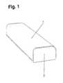
- FIG. 1illustrates a post-forming laminate glued to a longitudinal carrier
- FIG. 2illustrates a dilatation profile with a post-forming laminate glued thereto
- FIG. 3illustrates a finishing profile with a post-forming laminate glued thereto
- FIG. 4illustrates a transition profile with a post-forming laminate glued thereto
- FIG. 5illustrates an exploded view of a dilatation profile extending between uneven tile surfaces
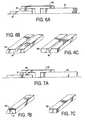
- FIGS. 6A-6Cillustrate an assembled view of a locking tab/reducer assembly
- FIGS. 7A-7Cillustrate an assembled view of a non-locking tab/reducer assembly
- FIG. 8illustrates an assembled view of a dilatation profile having two tab portions locking with edge panels
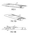
- FIG. 9shows a perspective view of the invention according to one embodiment of the invention.
- FIGS. 10-14illustrate tab designs according to other embodiments of the invention.
- the thickness of the post-forming laminate 1has been magnified as compared to the size of the carrier 2 and the profiles, e.g. 3 - 5 respectively, to better illustrate that a post-forming laminate 1 is glued to the carrier 2 and the profiles 3 - 5 respectively.
- the FIGS. 1-4only show one embodiment of the carrier 2 and the profiles 3 - 5 respectively which can be produced according to the invention. Various other designs are possible as shown in the other drawing figures.
- a roll of transparent so-called overlay paper of ⁇ -cellulose with a surface weight of 25 g/m 2is impregnated with an aqueous solution of melamine-formaldehyde resin to a resin content of 70 percent by weight calculated on dry impregnated paper.
- aluminium oxide particles with an average particle size of 50 ⁇ mare applied to the upper side of the paper in an amount of 7 g/m 2 by means of a doctor-roll placed above the paper web.
- the hard aluminium oxide particlesare then applied to the still-wet melamine-formaldehyde resin which has not dried.
- the impregnated paper webis then fed continuously into a heating oven, where the solvent in the resin evaporates. Simultaneously, the resin is partially cured to so-called B-stage. Thereby the aluminium oxide particles are enclosed in the resin layer and accordingly concentrated to the surface of the product obtained which is usually called a prepreg. The prepreg web obtained is then rolled again.
- a roll of conventional non-transparent decor paper with a decor pattern printed thereon and having a surface weight of 80 g/m 2is treated in the same way as the overlay paper except for the fact that no aluminium oxide particles are applied and that the resin content was 50 percent by weight calculated on dry impregnated paper.
- a roll of unimpregnated parchment with a surface weight of 120 g/m 2is used at the production of the post-forming laminate.
- the two prepreg webs impregnated with melamine-formaldehyde resin and the unimpregnated parchment webare then pressed between two press bands of a continuous laminating press to a decorative post-forming laminate.
- a prepreg web of ⁇ -celluloseis placed on top with the side with the hard particles directed upwards.
- Underneathfollows a prepreg web of decor paper and at the bottom a web of parchment.
- the prepreg webs and the parchment webare pressed together at a pressure of 35 kp/cm 2 and at a temperature of 170° C.
- the decorative post-forming laminate obtainedis then cut with roller knives to strips of suitable length and width.
- a longitudinal carrier 2 with a rectangular cross-section and two opposite rounded-off edges according to FIG. 1are machined from a fibre board or other substrate material by means of a milling machine.
- the fibre boardis a water resistant board of so-called MDF-quality (medium density fibre board quality) or, alternatively, HDF quality (high density fibre board quality), made of finely divided fibres with an adhesive to bond the fibres together.
- a strip of post-forming laminate 1is now glued under heat and pressure to the longitudinal carrier 2 with a heat and moisture resistant glue.
- the pressureis regulated with rolls which press the laminate against the carrier and the temperature 1 is regulated with heating nozzles which blow an even current of warm air.
- a dilation profile 3 according to FIG. 2can be machined from the laminate clad carrier by milling.
- Two finishing profiles 4 according to FIG. 3 or one transition profile 5 according to FIG. 4can be produced from the same carrier. This results in a rational and cost-saving production.
- the carrierscan be the shape as shown in FIGS. 2-9 before the post-forming of the laminate is commenced.
- FIG. 5shows an exploded view of one of the preferred embodiments of the invention, wherein floor strip 100 is attached between two differing sets of tiles, thin tile 70 and thicker tongue and groove tiles 80 and 81 (shown in mating relationship), all on a subfloor 500 .
- FIG. 6Ashows the components of FIG. 5 assembled together.
- floor strip 100is a dilatation profile having a T-shape, with a first plane 50 arranged vertically in use and a second plane 60 oriented horizontally and connecting to the first plane along its mid-section forming a “T.” The second plane overhangs the first plane on a first side 61 and a second side 62 .
- a tab 180extends from the bottom plane of first side 61 of the second plane.
- Reducer 90Due to the differing heights of the tiles 70 and 80 / 81 , a reducer 90 will be required to provide a smooth transition.
- Reducer 90has a height corresponding to the height difference between the tiles and also has a groove 91 on its upper surface for acceptance, in a locking manner, of tab 180 .
- the tabfits into groove 91 and then the reducer is assembled in mating position between an edge 71 of tile 70 and the first side 61 of the second plane.
- the design of the tab and reducerprevents the reducer from laterally moving in relation to floor strip 100 in an assembled condition.
- a simple tongue and groove designis shown, other engagement means may be used (See FIGS.
- the reducers 90(as well as the reducers of the subsequent described embodiments) may carry on an exposed outer surface a pot forming laminate (not shown) in a manner similar to that shown in FIGS. 1-4 .
- Reducer 90may have alternate designs, which are illustrated in FIGS. 6B and 6C .
- Reducer 90shown in FIGS. 5 , 6 A and 6 B, has a sloped portion 93 , which provides a more gradual transition between a tiled floor section having a higher height than an adjacent floor tile section.
- Reducer 95shown in FIG. 6C , has a vertical side 96 , which would provide more of a small step between the different tile floor sections.
- FIGS. 7A-7CAnother embodiment of the invention is shown in FIGS. 7A-7C , whereby instead of tab 180 locking into a reducer, it provides a back stop for a reducer 97 which does not have any groove.
- Other aspects of this embodimentare congruent to those of the previous embodiment and will not be repeated herein.
- Reducer 97is more or less a rectangular box design having one sloped side 109 which as in the previous embodiment provides a gradual transition between floor heights. Reducer 97 does not have a groove, rather the back side 99 is abutted against tab 180 when floor strip 100 and reducer 97 are in their assembled positions, as shown in FIG. 7A. A glue or other adhesive may be used to maintain the parts in their positions and prevent reducer 97 from laterally moving in relation to floor strip 100 . Alternatively, reducer 98 may be used in place of reducer 97 . Reducer 98 has a rectangular box shape which provides a step between floor heights rather than in a sloped fashion.
- FIG. 8A further embodiment of the invention is shown in FIG. 8 .
- floor strip 100is used between two adjacent floor tile sections having similar heights.
- both first side 61 and second side 62 of the second plane 60have tabs 180 and 181 , respectively.
- Tiles 200 and 210have grooves 201 and 211 respectively.
- Tabs 180 and 181fit into grooves 201 and 211 by a tongue and groove style, however, other engagement styles may be used (See FIGS. 9A-9F below) which either positively lock the parts together or simple provide a guide for assembly. Such a design does not require the use of a reducer between the tile and the floor strip.
- the tab and reducer grooveneed not be a simple tongue and groove design, as outlined in FIGS. 5-8 . These were described merely by way of example using floor strip 100 with tab portion 180 as shown in FIG. 9 . Alternatives of the tab on the floor strip in conjunction with a reducer are shown in FIGS. 10-14 . Additionally, the reducers described in conjunction with the invention as a spacer between uneven floor tiles is not necessary. Should the tiles have similar height, a reducer may be removed and such slots which are described in the reducer may also be cut into the appropriate floor tile for positive locking or prevention of associated movement.
- a tab 1800 on floor strip 101has the shape of a t-nut.
- An associated reducer 1000has a shape similar to the t-nut cut through its longitudinal length thereof.
- Tab 1800fits into the reducer 1000 by sliding the tab into an end portion of the reducer and along the length of the reducer. Such a design allows for a positive locking in a lateral direction while allowing movement along the longitudinal axis of the floor strip.
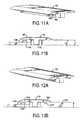
- FIGS. 11A , 12 A and 14 Ashow a tab portion that snaps into the associated reducer.
- a tab 1800 of floor strip 102has a pair of upwardly facing angled teeth 1850 and 1851 .
- a reducer 1100 used in association with tab 1800has a slot 1105 cut there through having an opening congruent to the design of the tab.
- Tabs 1802 , 1820 and 1803 shown in FIGS. 12A and 14Ahave a similar design for the upwardly facing teeth as shown in FIG. 11A , but have a differing number of teeth.
- reducers 1200 and 1400used in association with these tabs respectively, also have slots 1205 and 1405 which are congruent to the associated tabs.
- a tile 1225also has a slot near its edge for acceptance of the tab 1820 .
- Each slot designallows for the tab portion to be snapped into the associated slot for a positive locking between the tab and the slot.
- the slot drawn in these figureshas a shape congruent to the shape of the associated tab, such is not required.
- FIG. 12Balso shows a floor strip 103 having a pair of tabs whereby the tabs snap into both a reducer and the associated tile. However, such a specific case is not required.
- Floor strip 103may be snapped into a pair of tiles or a pair of reducers.
- floor strip 104has a pair of spaced tabs 1380 and 1381 having a generally triangular profile and extending along the length of the floor strip.
- Tabs 1380 and 1381provide a channel by which reducer 1300 is held between the tabs under floor strip 104 . Such a design prevents lateral movement of reducer 1300 in relation to floor strip 104 .
Landscapes
- Engineering & Computer Science (AREA)
- Architecture (AREA)
- Civil Engineering (AREA)
- Structural Engineering (AREA)
- Life Sciences & Earth Sciences (AREA)
- Manufacturing & Machinery (AREA)
- Wood Science & Technology (AREA)
- Forests & Forestry (AREA)
- Floor Finish (AREA)
Abstract
Description
This application is a continuation-in-part of U.S. Ser. No. 08/817,391, filed Apr. 25, 1997 now U.S. Pat. No. 6,517,935 and a continuation-in-part of U.S. Ser. No. 09/986,414, filed Nov. 8, 2001 now abandoned, the entire disclosures of which are hereby incorporated by reference.
1. Field of the Invention
The present invention relates to a process for the production of a floor strip such as a dilatation profile, a transition profile or a finishing profile. The present invention also relates to the features of the floor strip.
2. Description of the Related Art
It is previously known to produce floor strips such as metal strips, wood veneer coated strips and strips of homogeneous wood. However, such floor strips generally do not adequately match the pattern of the other portions of the floor. Thus, there is a strong desire to bring about a floor strip with the same pattern as on a floor of thermosetting laminate. During the last few years these floors have become very usual. For instance they are made with a wood pattern, marble pattern and fancy pattern. Possibly you can use a homogeneous wood strip or a wood veneer-coated strip for a few of the wood patterned floors. Previously known strips do not go well together with all the other floor patterns.
These floor strips are provided in a floor system in order to provide a transition or edge to the floor, such as at the corner of the wall or between rooms. They may also be provided between rooms having different types of flooring, such as carpet and tile, or different heights or textures of tiles. However, conventional floor strips do not adequately provide a transition between differing floor types because they cannot adequately cover the gap between the differing floor coverings or the differing heights of the tiles.
However, it also a problem for sellers of floor strips to inventory differing types of transition profiles, especially in a pattern or color to match a single floor. Thus, there exists a need to provide a single floor strip which can satisfy a number of differing requirements, such a being useful as a finishing profile, a dilatation profile, and a transition profile.
The purpose of the present invention is to provide a floor strip with improved abrasion resistance and features to overcome the problems in the art.
According to the present invention it has quite surprisingly been possible to meet the above needs and bring about a process for the production of floor strips such as a dilatation profile, a transition profile or a finishing profile. The process comprises glueing, preferably under heat and pressure a thin decorative thermosetting laminate of post-forming quality having an abrasion resistance measured as IP-value>3000 revolutions, preferably >6000 revolutions, on a longitudinal carrier, which carrier preferably consists of a fibre board or a particle board with a rectangular cross-section and at least two opposite rounded-off edges.
The post-forming laminate is glued in one piece on the upper side and two long sides of the carrier via the rounded-off edges, whereupon one or more floor profiles having the same or different cross-section is machined from the laminate coated carrier. According to another embodiment the carrier can be provided with a rectangular cross-section with three rounded-off edges.
From the same body, the laminate clad carrier, several profiles with varying shape can be machined. Usually a milling machine is used for machining the different kinds of profiles from the laminate coated carrier. The carrier may also be molded to achieve various profiles which may be required. Additionally, the carrier is preferably water resistant or even waterproof. In a preferred embodiment the carrier consists of a high density fibre board made of fine fibres, such as known in the industry as medium density fiberboard (MDF) or high density fiberboard (HDF).
Advantageously, a heat and moisture resistant glue is used at the glueing. Preferably the glueing is carried out under heat and pressure. For instance, the pressure can be regulated by means of rollers which press the laminate against the carrier. The temperature can, for instance, be regulated with heating nozzles which can give an even current of warm air.
Suitably the post-forming laminate consists of at least one monochromatic or patterned paper sheet impregnated with a thermosetting resin, preferably melamine-formaldehyde resin and preferably one or more sheets for instance of parchment, vulcanized fibres or glass fibres. The last mentioned sheets are preferably not impregnated with any thermosetting resin, but the thermosetting resin from the sheets situated above will enter these sheets at the laminating step, where all sheets are bonded together. Alternatively, the sheet can be a metallic foil or a layer of paint.
Generally the term post-forming laminate means a laminate which is so flexible that it can be formed at least to a certain extent after the production thereof. Ordinary qualities of thermosetting decorative laminates are rather brittle and cannot be regarded as post-forming laminates.
Usually the post-forming laminate includes at least one uppermost transparent paper sheet made of α-cellulose and impregnated with a thermosetting resin, preferably melamine-formaldehyde resin. This so-called overlay is intended to protect an underlying decor sheet from abrasion.
Often at least one of the paper sheets of the postforming laminate impregnated with thermosetting resin, preferably the uppermost one, is coated with hard particles, e.g., those having a Moh's hardness of at least 6, preferably between 6 and 10, similar to the Moh's hardness of at least silica, aluminium oxide, diamond and/or silicon carbide. The hard particles have an average particle size of about 1-80 μm, preferably about 5-60 μm evenly distributed over the surface of the paper sheet. In a preferred embodiment the hard particles are applied on the resin impregnated paper surface before the resin has been dried. The hard particles improve the abrasion resistance of the laminate. Hard particles are used in the same way at the production of laminates which are subject to a hard wear such as flooring laminates.
The abrasion resistance of the post-forming laminates is tested according to the European standard EN 438-2/6: 1991. According to this standard the abrasion of the decor sheet of the finished laminate to the so-called IP-point (initial point) is measured, where the starting abrasion takes place. The IP-value suitably lies within the interval 3000-20000, preferably 3000-10000 revolutions. Thus, the manufacturing process according to the invention makes it possible to produce laminate clad profiles with the same surface pattern and about the same abrasion resistance as the laminate floorings they are intended to be used together with.
The carriers for the floor strips to which the post-forming laminate is glued can be made of differing profiles to accommodate the specific circumstance, namely whether a dilatation, transition or finishing profile is required. The profile, for example a dilatation profile, comprises a general T-shape whereby a first plane extending vertically along the length of the floor strip intersects about in the middle of a second horizontally oriented plane. A profile removes about half of the second plane to form a rotated upside down L-shape, which is used adjacent a wall or on a stepped surface. A dilatation profile is similar to a finishing profile, but the second plane is oriented off of horizontal or it is divided into two planes, one at a different level than the other, or one side is removed altogether, which provides a smoother transition between uneven tiles, a carpet and tile, or differing tile textures. The pattern of the profiles can also be adapted to other flooring materials than laminate floorings, such as parquette floorings and soft plastic floorings.
In order to overcome the problems associated with transitioning between carpet and tile, differing textures of tiles or differing heights of tiles, the second plane may have a tab portion on its tile/carpet engaging surface depending orthogonally away from the second plane and displaced away from the first plane. The tab is used to engage a reducer that extends between the floor surface and the engagement surface of the second plane. The reducer is configured to maintain a horizontal orientation of the second plane and provide a smoother transition between the tile surfaces in the finishing, transition or dilatation profile when they are used between uneven tile surfaces, differing tile textures or between carpet and tile. The tab portion fits into a groove on the upper surface of the reducer in mating fashion to create a solid lock between them.
Alternatively, the tab portion may be engaged into the edge of a tile panel on the floor. In this situation, the tiles adjacent to the transition area may require a groove cut into them near the transition. Such allows the tab portion to maintain a firm and locked relationship with the tile surface and provide a better transition between the tile surface and the respective profile. Further, a tab portion may be provided on both sides of the second plane respective to the first plane to further smooth the transition area between the first tile surface, the floor strip and the second surface.
The design of the tab may come in varying styles, there may be a straight block type tab, a t-nut type, various interlocking styles and a channel type arrangement. Such types depend on the particular requirements of the tiling circumstance.
This inventive floor strip according to the above may be used as a transition piece between various tongue and groove panels to provide a smooth and aesthetic transition between floor sections having dissimilar surfaces, such as those between a carpeted area and a tiled area, a thin tile area and a hardwood floor, two tile areas having differing textures, etc.
The present invention will be explained further in connection with the embodiment example below and the enclosed figures of which:
In the figures of illustrating afloor strip 100, the thickness of thepost-forming laminate 1 has been magnified as compared to the size of thecarrier 2 and the profiles, e.g.3-5 respectively, to better illustrate that apost-forming laminate 1 is glued to thecarrier 2 and the profiles3-5 respectively. Of course theFIGS. 1-4 only show one embodiment of thecarrier 2 and the profiles3-5 respectively which can be produced according to the invention. Various other designs are possible as shown in the other drawing figures.
For example in one embodiment, a roll of transparent so-called overlay paper of α-cellulose with a surface weight of 25 g/m2is impregnated with an aqueous solution of melamine-formaldehyde resin to a resin content of 70 percent by weight calculated on dry impregnated paper. Immediately after the impregnation, aluminium oxide particles with an average particle size of 50 μm are applied to the upper side of the paper in an amount of 7 g/m2by means of a doctor-roll placed above the paper web. Thus, the hard aluminium oxide particles are then applied to the still-wet melamine-formaldehyde resin which has not dried.
The impregnated paper web is then fed continuously into a heating oven, where the solvent in the resin evaporates. Simultaneously, the resin is partially cured to so-called B-stage. Thereby the aluminium oxide particles are enclosed in the resin layer and accordingly concentrated to the surface of the product obtained which is usually called a prepreg. The prepreg web obtained is then rolled again.
A roll of conventional non-transparent decor paper with a decor pattern printed thereon and having a surface weight of 80 g/m2is treated in the same way as the overlay paper except for the fact that no aluminium oxide particles are applied and that the resin content was 50 percent by weight calculated on dry impregnated paper.
A roll of unimpregnated parchment with a surface weight of 120 g/m2is used at the production of the post-forming laminate.
The two prepreg webs impregnated with melamine-formaldehyde resin and the unimpregnated parchment web are then pressed between two press bands of a continuous laminating press to a decorative post-forming laminate. At the pressing, a prepreg web of α-cellulose is placed on top with the side with the hard particles directed upwards. Underneath follows a prepreg web of decor paper and at the bottom a web of parchment. The prepreg webs and the parchment web are pressed together at a pressure of 35 kp/cm2and at a temperature of 170° C. The decorative post-forming laminate obtained is then cut with roller knives to strips of suitable length and width.
Alongitudinal carrier 2 with a rectangular cross-section and two opposite rounded-off edges according toFIG. 1 are machined from a fibre board or other substrate material by means of a milling machine. The fibre board is a water resistant board of so-called MDF-quality (medium density fibre board quality) or, alternatively, HDF quality (high density fibre board quality), made of finely divided fibres with an adhesive to bond the fibres together.
A strip ofpost-forming laminate 1 is now glued under heat and pressure to thelongitudinal carrier 2 with a heat and moisture resistant glue. The pressure is regulated with rolls which press the laminate against the carrier and thetemperature 1 is regulated with heating nozzles which blow an even current of warm air.
Following the above process, the abrasion resistance of the post-forming laminate obtained was measured. Then a value for the IP-point amounting to 7000 revolutions was obtained.
The different structures and designs of the profiles forfloor strip 100, namely the dilatation, finishing and transition will now be described with respect toFIGS. 2-9 . Adilation profile 3 according toFIG. 2 can be machined from the laminate clad carrier by milling. Two finishingprofiles 4 according toFIG. 3 or onetransition profile 5 according toFIG. 4 can be produced from the same carrier. This results in a rational and cost-saving production. Alternatively, the carriers can be the shape as shown inFIGS. 2-9 before the post-forming of the laminate is commenced.
Due to the differing heights of thetiles reducer 90 will be required to provide a smooth transition.Reducer 90 has a height corresponding to the height difference between the tiles and also has a groove91 on its upper surface for acceptance, in a locking manner, oftab 180. Upon assembly oftiles floor strip 100, the tab fits into groove91 and then the reducer is assembled in mating position between an edge71 oftile 70 and thefirst side 61 of the second plane. The design of the tab and reducer prevents the reducer from laterally moving in relation tofloor strip 100 in an assembled condition. Although a simple tongue and groove design is shown, other engagement means may be used (SeeFIGS. 9A-9F , discussed below) which have locking designs which lock the floor strip and reducer together. At each of these mating portions, glue may be used to additionally secure the components together. The reducers90 (as well as the reducers of the subsequent described embodiments) may carry on an exposed outer surface a pot forming laminate (not shown) in a manner similar to that shown inFIGS. 1-4 .
Another embodiment of the invention is shown inFIGS. 7A-7C , whereby instead oftab 180 locking into a reducer, it provides a back stop for areducer 97 which does not have any groove. Other aspects of this embodiment are congruent to those of the previous embodiment and will not be repeated herein.
A further embodiment of the invention is shown in FIG.8. In this embodiment,floor strip 100 is used between two adjacent floor tile sections having similar heights. Further, bothfirst side 61 andsecond side 62 of thesecond plane 60 havetabs Tiles grooves Tabs grooves FIGS. 9A-9F below) which either positively lock the parts together or simple provide a guide for assembly. Such a design does not require the use of a reducer between the tile and the floor strip.
The tab and reducer groove need not be a simple tongue and groove design, as outlined inFIGS. 5-8 . These were described merely by way of example usingfloor strip 100 withtab portion 180 as shown in FIG.9. Alternatives of the tab on the floor strip in conjunction with a reducer are shown inFIGS. 10-14 . Additionally, the reducers described in conjunction with the invention as a spacer between uneven floor tiles is not necessary. Should the tiles have similar height, a reducer may be removed and such slots which are described in the reducer may also be cut into the appropriate floor tile for positive locking or prevention of associated movement.
InFIG. 10A , atab 1800 onfloor strip 101 has the shape of a t-nut. An associatedreducer 1000 has a shape similar to the t-nut cut through its longitudinal length thereof.Tab 1800 fits into thereducer 1000 by sliding the tab into an end portion of the reducer and along the length of the reducer. Such a design allows for a positive locking in a lateral direction while allowing movement along the longitudinal axis of the floor strip.
The designs of the tab portion as shown inFIGS. 11A ,12A and14A show a tab portion that snaps into the associated reducer. InFIG. 11A , atab 1800 offloor strip 102 has a pair of upwardly facingangled teeth reducer 1100 used in association withtab 1800 has aslot 1105 cut there through having an opening congruent to the design of the tab. Whentab 1800 andreducer 1100 are assembled together,floor strip 102 is placed atop the reducer. Upon sufficient pressure on the floor strip,tabs 1801 will snap into theslot 1105.Teeth tab 1801 from being removed fromslot 1105 ofreducer 1100 providing a positive locking together.
InFIG. 13A ,floor strip 104 has a pair of spacedtabs Tabs reducer 1300 is held between the tabs underfloor strip 104. Such a design prevents lateral movement ofreducer 1300 in relation tofloor strip 104.
Although the present invention has been described and illustrated in detail, such explanation is to be clearly understood that the same is by way of illustration and example only, and is not to be taken by way of limitation. Other modifications of the above examples may be made by those having ordinary skill which remain within the scope of the invention. For instance, the examples are described with reference to a dilatation profile for the carrier of the floor strip. However, such tab and reducer designs work just as well with a finishing profile as well as a transition profile, and whether used on carpet or floor tiles.
Claims (18)
1. A floor strip assembly to cover a gap between a first and second floor surface, comprising a longitudinal carrier comprising a rib extending along a longitudinal axis thereof, a plane extending orthogonal to the rib having an engaging surface and an upper surface, and a tab portion on the engaging surface extending away from the engaging surface, and a thermosetting laminate comprising hard particles which impart abrasion resistance to the laminate, wherein the laminate is glued onto the upper surface, an upper end of the rib attaches to the plane along a central axis thereof to form substantially a T-shape profile for the floor strip, dividing the plane into a first side and a second side, the tab portion is located on the first side engaging surface of the plane and a second tab portion is located on the second side engaging surface of the plane and extends orthogonal therefrom, and at least one of the first and second tab portions engages a channel in one of the first and second floor surfaces.
2. The floor strip assembly according toclaim 1 , further comprising a reducer having an upper side that engages the engaging surface and a channel within the upper side that engages the tab portion.
3. The floor strip assembly according toclaim 2 , wherein the reducer is assembled between the first floor surface and the engaging surface and is configured to keep the plane in a horizontal orientation when the first and second floor surfaces have different thicknesses.
4. The floor strip assembly according toclaim 2 , wherein the tab portion slidingly engages the channel when the reducer engages the engaging surface.
5. The floor strip assembly according toclaim 2 , wherein the tab portion snap-fits into the channel.
6. The floor strip assembly according toclaim 1 , wherein the tab portion is one of a general hook shape, and a lip is formed at a point of the hook, and a generally bulbous shape having a plurality of vertically spaced, upwardly facing teeth.
7. The floor strip assembly according toclaim 1 , further comprising a reducer having an upper side that engages the engaging surface and an inner side that abuts the tab portion to prevent lateral movement thereof.
8. The floor assembly according toclaim 7 , wherein the tab portion is one of a generally rectangular shape abutting the inner side of the reducer, and a pair of extensions, which abut an outer and the inner side, respectively, of the reducer.
9. The floor strip assembly according toclaim 1 , wherein the tab portion engages a channel in the first floor surface.
10. The floor strip assembly according toclaim 1 , wherein the upper surface comprises a generally planar surface with two opposite rounded-off edges.
11. The floor strip assembly according toclaim 10 , wherein the laminate covers substantially the entire planar surface and along the rounded-off edges.
12. The floor strip assembly according toclaim 1 , wherein the carrier is water resistant.
13. The floor strip assembly according toclaim 1 , wherein the laminate comprises at least one patterned paper impregnated with a thermosetting resin.
14. The floor strip assembly according toclaim 13 , wherein the thermosetting resin is melamine-formaldehyde.
15. The floor strip assembly according toclaim 13 , wherein the laminate further comprises one or more sheets consisting of fibers selected from parchment, vulcanized or glass fibers which are not impregnated with a thermosetting resin.
16. The floor strip assembly according toclaim 1 , wherein an upper most sheet of the laminate is coated with hard particles selected from the group consisting of silica, aluminum oxide, silicon carbide and combinations thereof, the hard particles having an average size of 1-80 μ.
17. The floor strip assembly according toclaim 1 , wherein the laminate comprises at least one transparent overlay of α-cellulose impregnated with a thermosetting resin.
18. The floor strip assembly according toclaim 17 , wherein the overlay is impregnated with melamine-formaldehyde resin.
Priority Applications (5)
| Application Number | Priority Date | Filing Date | Title |
|---|---|---|---|
| US10/319,820US6898911B2 (en) | 1997-04-25 | 2002-12-16 | Floor strip |
| US10/902,062US7065931B2 (en) | 1994-10-24 | 2004-07-30 | Floor strip |
| US11/140,075US7150134B2 (en) | 1994-10-24 | 2005-05-31 | Floor strip |
| US11/400,519US7640705B2 (en) | 1994-10-24 | 2006-04-10 | Floor strip |
| US11/640,351US8448399B2 (en) | 1994-10-24 | 2006-12-18 | Floor strip |
Applications Claiming Priority (3)
| Application Number | Priority Date | Filing Date | Title |
|---|---|---|---|
| US08/817,391US6517935B1 (en) | 1994-10-24 | 1995-10-17 | Process for the production of a floor strip |
| US09/986,414US20030084634A1 (en) | 2001-11-08 | 2001-11-08 | Transition molding |
| US10/319,820US6898911B2 (en) | 1997-04-25 | 2002-12-16 | Floor strip |
Related Parent Applications (4)
| Application Number | Title | Priority Date | Filing Date |
|---|---|---|---|
| PCT/SE1995/001206Continuation-In-PartWO1996012857A1 (en) | 1994-10-24 | 1995-10-17 | Process for the production of a floor strip |
| US08817391Continuation-In-Part | 1995-10-17 | ||
| US08/817,391Continuation-In-PartUS6517935B1 (en) | 1994-10-24 | 1995-10-17 | Process for the production of a floor strip |
| US09/986,414Continuation-In-PartUS20030084634A1 (en) | 1994-10-24 | 2001-11-08 | Transition molding |
Related Child Applications (2)
| Application Number | Title | Priority Date | Filing Date |
|---|---|---|---|
| US29/208,500DivisionUSD504730S1 (en) | 1994-10-24 | 2004-06-30 | Laminate dilation molding |
| US10/902,062DivisionUS7065931B2 (en) | 1994-10-24 | 2004-07-30 | Floor strip |
Publications (2)
| Publication Number | Publication Date |
|---|---|
| US20030159389A1 US20030159389A1 (en) | 2003-08-28 |
| US6898911B2true US6898911B2 (en) | 2005-05-31 |
Family
ID=27760671
Family Applications (3)
| Application Number | Title | Priority Date | Filing Date |
|---|---|---|---|
| US10/319,820Expired - LifetimeUS6898911B2 (en) | 1994-10-24 | 2002-12-16 | Floor strip |
| US10/902,062Expired - Fee RelatedUS7065931B2 (en) | 1994-10-24 | 2004-07-30 | Floor strip |
| US11/400,519Expired - Fee RelatedUS7640705B2 (en) | 1994-10-24 | 2006-04-10 | Floor strip |
Family Applications After (2)
| Application Number | Title | Priority Date | Filing Date |
|---|---|---|---|
| US10/902,062Expired - Fee RelatedUS7065931B2 (en) | 1994-10-24 | 2004-07-30 | Floor strip |
| US11/400,519Expired - Fee RelatedUS7640705B2 (en) | 1994-10-24 | 2006-04-10 | Floor strip |
Country Status (1)
| Country | Link |
|---|---|
| US (3) | US6898911B2 (en) |
Cited By (58)
| Publication number | Priority date | Publication date | Assignee | Title |
|---|---|---|---|---|
| US20030205013A1 (en)* | 2002-05-03 | 2003-11-06 | Faus Group, Inc. | Flooring system having complementary sub-panels |
| US20040009320A1 (en)* | 2002-05-03 | 2004-01-15 | Garcia Eugenio Cruz | Flooring system having complementary sub-panels |
| US20040074191A1 (en)* | 2002-05-03 | 2004-04-22 | Garcia Eugenio Cruz | Flooring system having microbevels |
| US20040200165A1 (en)* | 2002-05-03 | 2004-10-14 | Faus Group, Inc | Flooring system having sub-panels |
| US20040258907A1 (en)* | 1994-10-24 | 2004-12-23 | Pergo (Europe) Ab | Process for the production of a floor strip |
| US20050150182A1 (en)* | 2001-11-08 | 2005-07-14 | Pergo (Europe) Ab | Transition molding |
| US20050229517A1 (en)* | 2004-03-15 | 2005-10-20 | Gomez Insa Jose F | Molding profile and molding profile assembly |
| US20060005498A1 (en)* | 2004-07-07 | 2006-01-12 | Vincente Sabater | Flooring system having sub-panels with complementary edge patterns |
| US20060150565A1 (en)* | 2005-01-12 | 2006-07-13 | Benny Schacht | Finishing set for floor covering and holder, as well as finishing profile, for a finishing set, and method for manufacturing a finishing profile and a skirting board |
| US20060260254A1 (en)* | 2005-05-20 | 2006-11-23 | Valinge Aluminium Ab | Mechanical Locking System For Floor Panels |
| WO2007008138A1 (en)* | 2005-07-11 | 2007-01-18 | Pergo (Europe) Ab | A joint profile for a panel |
| USD542941S1 (en) | 2005-07-15 | 2007-05-15 | Neuhofer Jr Franz | Combined profiled cover for bridging a gap in a floor covering and a step |
| USD542939S1 (en) | 2005-07-15 | 2007-05-15 | Neuhofer Jr Franz | Combined profiled cover for bridging a gap in a floor covering and an additional profiled cover for covering the edge of a floor covering |
| USD542940S1 (en) | 2005-07-15 | 2007-05-15 | Neuhofer Jr Franz | Profiled cover for bridging a gap between floor coverings of different heights |
| USD543287S1 (en) | 2005-07-15 | 2007-05-22 | Neuhofer Jr Franz | Profiled cover for bridging a gap in a floor covering |
| US20070137129A1 (en)* | 2005-12-21 | 2007-06-21 | Herm. Friedr. Kuenne Gmbh & Co. | Profile-rail system |
| US20070266638A1 (en)* | 2004-02-27 | 2007-11-22 | Neuhofer Franz Jr | Device for Bridging a Difference in Height Between Two Floor Surfaces |
| US20070283654A1 (en)* | 2006-05-25 | 2007-12-13 | Pfleiderer Schweiz Ag | Break-away multi-purpose flooring transition |
| US20070287004A1 (en)* | 2006-05-25 | 2007-12-13 | Gottzmann Andreas M | Laminate and Method of Manufacture |
| US20080034691A1 (en)* | 2006-04-26 | 2008-02-14 | Illinois Tool Works, Inc. | Laminate-clad floor molding and method for manufacture |
| US20080034700A1 (en)* | 2006-05-25 | 2008-02-14 | Pergo (Europe) Ab | Break-away multi-purpose flooring transition |
| US20080034696A1 (en)* | 2004-02-27 | 2008-02-14 | Neuhofer Franz Jun | Covering Device for Floor Coverings |
| US20080053029A1 (en)* | 2006-08-08 | 2008-03-06 | Ricker Michael B | Glueless panel locking system |
| US20080134607A1 (en)* | 2004-10-22 | 2008-06-12 | Valinge Innovation Ab | Mechanical Locking of Floor Panels With a Flexible Tongue |
| US20080168736A1 (en)* | 2002-04-22 | 2008-07-17 | Valinge Innovation Ab | Floorboards, flooring systems and method for manufacturing and installation thereof |
| US20080168730A1 (en)* | 2001-09-20 | 2008-07-17 | Valinge Innovation Ab | Flooring and method for laying and manufacturing the same |
| US20080168729A1 (en)* | 2006-10-18 | 2008-07-17 | Pfleiderer Schweiz Ag | Transitions having disparate surfaces |
| USD574975S1 (en) | 2005-06-03 | 2008-08-12 | Neuhofer Jr Franz | Profile assembly |
| US20080263983A1 (en)* | 2006-11-13 | 2008-10-30 | Pergo (Europe) Ab | Flush or near-flush flooring transitions |
| US20090087643A1 (en)* | 2007-10-02 | 2009-04-02 | Gottzmann Andreas M | Laminate Surface Layer Without an Overlay and Method of Manufacture |
| US20100112667A1 (en)* | 2008-11-03 | 2010-05-06 | Cfd Research Corporation | Microfluidic Biological Extraction Chip |
| US20100218448A1 (en)* | 2006-02-07 | 2010-09-02 | Flooring Industries Limited, Sarl | Finishing Profile For A Floor Covering And Methods For Manufacturing Such Finishing Profile |
| US20100242393A1 (en)* | 2009-03-27 | 2010-09-30 | Sven Kornfalt | Joint cover assembly and kit comprising this joint cover assembly as well as installation method thereof |
| US20110041996A1 (en)* | 2003-12-02 | 2011-02-24 | Valinge Innovation Ab | Floorboard, system and method for forming a flooring, and a flooring formed thereof |
| US20110056167A1 (en)* | 2009-09-04 | 2011-03-10 | Valinge Innovation Ab | Resilient floor |
| US20110088345A1 (en)* | 2005-03-30 | 2011-04-21 | Valinge Innovation Ab | Mechanical locking system for panels and method of installing same |
| US20110223670A1 (en)* | 2010-03-05 | 2011-09-15 | Texas Heart Institute | Ets2 and mesp1 generate cardiac progenitors from fibroblasts |
| US8245478B2 (en) | 2006-01-12 | 2012-08-21 | Välinge Innovation AB | Set of floorboards with sealing arrangement |
| US20120222374A1 (en)* | 2008-06-20 | 2012-09-06 | Larry Bucheger | Wall system |
| US8539731B2 (en) | 2005-05-23 | 2013-09-24 | Pergo (Europe) Ab | Transition molding and installation methods therefor |
| US8584423B2 (en) | 2001-07-27 | 2013-11-19 | Valinge Innovation Ab | Floor panel with sealing means |
| US8689512B2 (en) | 2006-11-15 | 2014-04-08 | Valinge Innovation Ab | Mechanical locking of floor panels with vertical folding |
| US8800150B2 (en) | 2003-02-24 | 2014-08-12 | Valinge Innovation Ab | Floorboard and method for manufacturing thereof |
| US8869485B2 (en) | 2006-12-08 | 2014-10-28 | Valinge Innovation Ab | Mechanical locking of floor panels |
| US8875460B2 (en) | 1999-11-05 | 2014-11-04 | Faus Group, Inc. | Direct laminated floor |
| US9314936B2 (en) | 2011-08-29 | 2016-04-19 | Valinge Flooring Technology Ab | Mechanical locking system for floor panels |
| US9322183B2 (en) | 2004-01-13 | 2016-04-26 | Valinge Innovation Ab | Floor covering and locking systems |
| US9528276B2 (en) | 1998-06-03 | 2016-12-27 | Valinge Innovation Ab | Locking system and flooring board |
| US10059084B2 (en) | 2014-07-16 | 2018-08-28 | Valinge Innovation Ab | Method to produce a thermoplastic wear resistant foil |
| US20180291634A1 (en)* | 2017-03-31 | 2018-10-11 | James Hardie Technology Limited | Fiber cement articles with ultra-smooth exterior surface and methods for manufacturing same |
| US10301830B2 (en) | 2013-03-25 | 2019-05-28 | Valinge Innovation Ab | Floorboards provided with a mechanical locking system |
| US10486399B2 (en) | 1999-12-14 | 2019-11-26 | Valinge Innovation Ab | Thermoplastic planks and methods for making the same |
| US20190383029A1 (en)* | 2018-06-14 | 2019-12-19 | Société en Commandite Prolam | Slip-resistant floor for a cargo-carrying apparatus |
| US10801213B2 (en) | 2018-01-10 | 2020-10-13 | Valinge Innovation Ab | Subfloor joint |
| US11260619B2 (en)* | 2019-04-25 | 2022-03-01 | The Boeing Company | Composite panel systems and methods |
| US11578495B2 (en) | 2018-12-05 | 2023-02-14 | Valinge Innovation Ab | Subfloor joint |
| US11725395B2 (en) | 2009-09-04 | 2023-08-15 | Välinge Innovation AB | Resilient floor |
| US12215505B2 (en) | 2009-09-04 | 2025-02-04 | Välinge Innovation AB | Resilient floor |
Families Citing this family (63)
| Publication number | Priority date | Publication date | Assignee | Title |
|---|---|---|---|---|
| US6898911B2 (en) | 1997-04-25 | 2005-05-31 | Pergo (Europe) Ab | Floor strip |
| USD504730S1 (en) | 1994-10-24 | 2005-05-03 | Pergo (Europe) Ab | Laminate dilation molding |
| US7150134B2 (en) | 1994-10-24 | 2006-12-19 | Pergo (Europe) Ab | Floor strip |
| SE9500810D0 (en) | 1995-03-07 | 1995-03-07 | Perstorp Flooring Ab | Floor tile |
| US7131242B2 (en) | 1995-03-07 | 2006-11-07 | Pergo (Europe) Ab | Flooring panel or wall panel and use thereof |
| US7992358B2 (en) | 1998-02-04 | 2011-08-09 | Pergo AG | Guiding means at a joint |
| SE514645C2 (en) | 1998-10-06 | 2001-03-26 | Perstorp Flooring Ab | Floor covering material comprising disc-shaped floor elements intended to be joined by separate joint profiles |
| SE518184C2 (en) | 2000-03-31 | 2002-09-03 | Perstorp Flooring Ab | Floor covering material comprising disc-shaped floor elements which are joined together by means of interconnecting means |
| SE518212C2 (en)* | 2000-06-09 | 2002-09-10 | Goeteborgs List Och Traeindust | BASEBOARD |
| US7559177B2 (en)* | 2001-11-08 | 2009-07-14 | Pergo (Europe) Ab | Smooth flooring transitions |
| USD504181S1 (en) | 2001-11-08 | 2005-04-19 | Pergo (Europe) Ab | Laminate transition molding |
| US8468769B2 (en)* | 2003-12-31 | 2013-06-25 | Pergo (Europe) Ab | Reversible decorative moldings between floor and wall or wall and ceiling |
| DE10252865A1 (en)* | 2002-11-12 | 2004-05-27 | Kronotec Ag | Process for creating a structured decoration in a wood-based panel |
| DE10252866B3 (en) | 2002-11-12 | 2004-04-29 | Kronotec Ag | Panel used as a floor panel in laminate flooring comprises a support plate made of sized and compacted fiber material and having an upper side with a lower density than a lower side |
| US7617651B2 (en)* | 2002-11-12 | 2009-11-17 | Kronotec Ag | Floor panel |
| DE10252863B4 (en)* | 2002-11-12 | 2007-04-19 | Kronotec Ag | Wood fiber board, in particular floor panel |
| DE50309830D1 (en)* | 2002-11-15 | 2008-06-26 | Flooring Technologies Ltd | Device consisting of two interconnected construction panels and an insert for locking these building panels |
| DE10306118A1 (en) | 2003-02-14 | 2004-09-09 | Kronotec Ag | building board |
| US7678425B2 (en) | 2003-03-06 | 2010-03-16 | Flooring Technologies Ltd. | Process for finishing a wooden board and wooden board produced by the process |
| DE20304761U1 (en)* | 2003-03-24 | 2004-04-08 | Kronotec Ag | Device for connecting building boards, in particular floor panels |
| DE10362218B4 (en)* | 2003-09-06 | 2010-09-16 | Kronotec Ag | Method for sealing a building board |
| DE20315676U1 (en)* | 2003-10-11 | 2003-12-11 | Kronotec Ag | Panel, especially floor panel |
| US7506481B2 (en) | 2003-12-17 | 2009-03-24 | Kronotec Ag | Building board for use in subfloors |
| DE102004005047B3 (en)* | 2004-01-30 | 2005-10-20 | Kronotec Ag | Method and device for introducing a strip forming the spring of a plate |
| DE102004011531C5 (en)* | 2004-03-08 | 2014-03-06 | Kronotec Ag | Wood-based panel, in particular floor panel |
| DE102004011931B4 (en)* | 2004-03-11 | 2006-09-14 | Kronotec Ag | Insulation board made of a wood-material-binder fiber mixture |
| ITMI20041578A1 (en)* | 2004-07-30 | 2004-10-30 | Tocchio S R L | METHOD FOR THE REALIZATION OF DECORATIVE AND LAMINATED PAPERS WITH HIGH ABRASION RESISTANCE, IN PARTICULAR FOR FLOORING. |
| US20060101760A1 (en)* | 2004-11-03 | 2006-05-18 | Cahoon Michael L | Vapor barrier and cavity seal |
| US8146313B2 (en)* | 2005-01-25 | 2012-04-03 | Depro France | Multifunction finishing assembly for floor covering, a method for manufacturing and a method for laying said assembly |
| AT501890B1 (en)* | 2005-04-20 | 2006-12-15 | Neuhofer Martin | METHOD FOR PRODUCING FLOOR PROFILES FROM A WOODEN MATERIAL |
| US20080263979A1 (en)* | 2005-05-20 | 2008-10-30 | Timothy Randall Richardson | Interlocking interior trim |
| CN101310084A (en)* | 2005-08-08 | 2008-11-19 | 克劳诺斯潘技术有限公司 | Flush positioned shaped expansion element |
| US7854986B2 (en)* | 2005-09-08 | 2010-12-21 | Flooring Technologies Ltd. | Building board and method for production |
| DE102005042658B3 (en)* | 2005-09-08 | 2007-03-01 | Kronotec Ag | Tongued and grooved board for flooring has at least one side surface and tongue and/or groove with decorative layer applied |
| DE102005042657B4 (en)* | 2005-09-08 | 2010-12-30 | Kronotec Ag | Building board and method of manufacture |
| DE102005051756A1 (en)* | 2005-10-27 | 2007-05-03 | Basf Ag | An aminoplast resin film comprising paper impregnated with an aminoplast resin mixture containing inorganic nanoparticles |
| DE102005063034B4 (en) | 2005-12-29 | 2007-10-31 | Flooring Technologies Ltd. | Panel, in particular floor panel |
| DE102006006124A1 (en)* | 2006-02-10 | 2007-08-23 | Flooring Technologies Ltd. | Device for locking two building panels |
| DE102006007976B4 (en)* | 2006-02-21 | 2007-11-08 | Flooring Technologies Ltd. | Process for refining a building board |
| FR2899615B1 (en)* | 2006-04-10 | 2008-06-06 | Bernard Francois Michel Proot | UNIQUE FINISHING DEVICE HAVING THREE USE FUNCTIONS FOR WOOD OR SIMILAR FLOOR COATING |
| US20080060304A1 (en)* | 2006-09-13 | 2008-03-13 | Eucatex S/A Industria E Comercio | Constructive arrangement in floor finishing element |
| US20080060292A1 (en)* | 2006-09-13 | 2008-03-13 | Eucatex S/A Industria E Comercio | Constructive arrangement in floor finishing element |
| US7793483B2 (en)* | 2006-09-18 | 2010-09-14 | Pergo AG | Ventilated floor moldings |
| USD665211S1 (en) | 2009-08-06 | 2012-08-14 | Bender James J | Flexible sample of replica wood flooring |
| US20110045453A1 (en) | 2009-08-21 | 2011-02-24 | Bender James J | Kit Of Pre-Construction Samples For Replicating Construction Products |
| US8241039B2 (en)* | 2009-08-21 | 2012-08-14 | Bender James J | Kit of pre-construction samples for replicating construction products |
| USD677955S1 (en) | 2010-06-10 | 2013-03-19 | James J. Bender | Flexible sample of a countertop replica |
| DE102010004717A1 (en) | 2010-01-15 | 2011-07-21 | Pergo (Europe) Ab | Set of panels comprising retaining profiles with a separate clip and method for introducing the clip |
| CN104831904B (en) | 2010-05-10 | 2017-05-24 | 佩尔戈(欧洲)股份公司 | Set of panels |
| USD716086S1 (en) | 2010-06-10 | 2014-10-28 | James J. Bender | Flexible sample of a cabinet replica |
| US8096093B1 (en)* | 2010-09-02 | 2012-01-17 | Pinky Yin Wah Poon | Groutless wall tile systems |
| DE102010047752A1 (en)* | 2010-10-08 | 2012-04-12 | Pergo AG | cover assembly |
| USD731078S1 (en)* | 2013-07-25 | 2015-06-02 | Chad Marcus Frenette | Transition strip |
| US20220381031A1 (en)* | 2013-10-25 | 2022-12-01 | Mbrico, Llc | Tile and Support Structure |
| US10428533B2 (en)* | 2017-05-19 | 2019-10-01 | Natalie A. Magnusson | Wall panel system |
| US11752661B2 (en)* | 2018-05-21 | 2023-09-12 | 5R Technologies Sdn. Bhd. | Natural effect panel and method of fabricating the same |
| CN111503869A (en)* | 2019-01-31 | 2020-08-07 | 青岛海尔空调器有限总公司 | Decorative strip and cabinet air conditioner indoor unit with same |
| US11047139B2 (en) | 2019-07-09 | 2021-06-29 | Schluter Systems L.P. | Veneer profile with fastening feature and related methods |
| US12269251B2 (en) | 2019-11-01 | 2025-04-08 | Thorhammer, LLC. | Floor and wall panel system |
| USD988541S1 (en)* | 2020-10-02 | 2023-06-06 | Daniel Cortavitarte Pérez | Draft excluder for doors and windows |
| GB202118013D0 (en)* | 2021-12-13 | 2022-01-26 | Labonte Paul Andre | Transition molding |
| USD1054595S1 (en) | 2022-01-26 | 2024-12-17 | Mcs Industries, Inc. | Connector for molding |
| USD1057216S1 (en) | 2022-01-26 | 2025-01-07 | Mcs Industries, Inc. | Molding |
Citations (56)
| Publication number | Priority date | Publication date | Assignee | Title |
|---|---|---|---|---|
| US1357713A (en) | 1918-11-16 | 1920-11-02 | Monarch Metal Products Company | Weather-strip for expansion-joints |
| DE467150C (en) | 1927-01-08 | 1929-06-18 | Winkel G M B H R | Microscope for meat inspection or similar purposes |
| US2100238A (en) | 1936-04-08 | 1937-11-23 | John I Burgess | Metallic expansion joint |
| US2194086A (en) | 1938-11-16 | 1940-03-19 | Speedwall Co | Panel joint construction |
| US2363429A (en) | 1940-02-12 | 1944-11-21 | Libbey Owens Ford Glass Co | Wall mounting |
| US3162906A (en) | 1961-04-05 | 1964-12-29 | Tracey Cook Brunstrom & Dudley | Separating strips for wall joints |
| US3199258A (en) | 1962-02-23 | 1965-08-10 | Robertson Co H H | Building outer wall structure |
| US3286425A (en) | 1964-06-19 | 1966-11-22 | Brown Co D S | Joint seals |
| US3331171A (en) | 1964-06-09 | 1967-07-18 | Edward C Hallock | Joint covers |
| US3339329A (en) | 1965-05-18 | 1967-09-05 | Edward T Berg | Arrangement for securing panels to the surface of a roof or wall |
| US3363381A (en) | 1965-09-03 | 1968-01-16 | Dow Chemical Co | Modular panel joining means with expandable locking strips |
| US3488828A (en) | 1967-11-30 | 1970-01-13 | Ppg Industries Inc | Means and method for inserting a structural gasket locking strip |
| US3665666A (en) | 1970-12-03 | 1972-05-30 | Andre Delcroix | Devices for interconnecting plates |
| US3671369A (en) | 1970-05-06 | 1972-06-20 | Aim Products Inc | Universal molding strip for trimming |
| US3696575A (en)* | 1971-06-07 | 1972-10-10 | Metalines Inc | Expansion joint cover |
| US3745726A (en) | 1971-11-15 | 1973-07-17 | Architectural Art Mfg | Floor joint cover assembly |
| US3758650A (en)* | 1969-01-22 | 1973-09-11 | J Hurst | Nal waterstop for use in forming joints in concrete method of sealing shuttering against a deformable section of an exter |
| US3760544A (en) | 1971-05-27 | 1973-09-25 | Tetra Plastics | Sealing gasket with elongated internal stiffner |
| US3810707A (en) | 1969-08-22 | 1974-05-14 | Minnesota Mining & Mfg | Joint structure and method |
| US4067155A (en) | 1975-08-28 | 1978-01-10 | Grefco, Inc. | Sealing system |
| US4198455A (en) | 1978-12-21 | 1980-04-15 | Pan American Gyro-Tex Corporation | Trim and molding strip and the method of forming same |
| US4292774A (en) | 1978-12-22 | 1981-10-06 | Dr. Ing. H.C.F. Porsche Aktiengesellschaft | Window mounting for automotive vehicles |
| US4455803A (en) | 1981-08-17 | 1984-06-26 | Mero-Raumstruktur Gmbh & Co. Wurzburg | Apparatus for sealing flat elements together, particularly roof elements |
| US4461131A (en) | 1982-05-21 | 1984-07-24 | Aar Corporation | Panel interconnection system |
| US4504347A (en) | 1975-10-31 | 1985-03-12 | Werzalit Pressholzwerk J. F. Werz Jr. Kg | Method of hot pressing a synthetic-resin laminate |
| US4520062A (en)* | 1982-11-16 | 1985-05-28 | Nevamar Corporation | Transfer coating of abrasion-resistant layers |
| US4643237A (en) | 1984-03-14 | 1987-02-17 | Jean Rosa | Method for fabricating molding or slotting boards such as shutter slats, molding for carpentry or for construction and apparatus for practicing this process |
| DE3640822A1 (en) | 1986-11-28 | 1988-06-09 | Schade Wilhelm Fa | Profile-rail kit |
| US5034272A (en) | 1988-08-25 | 1991-07-23 | Perstorp Ab | Decorative thermosetting laminate |
| US5074089A (en) | 1987-09-04 | 1991-12-24 | Mero-Raumstruktur Gmbh & Co. | Sealing device for facades and/or roofs |
| US5155952A (en)* | 1987-11-12 | 1992-10-20 | Mero-Raumstruktur Gmbh & Co. | Glazing profile strip for solid glazing or filler elements on the outer faces of buildings |
| US5365713A (en) | 1992-12-14 | 1994-11-22 | Pawling Corporation | Elastomeric seismic seal system |
| WO1996012857A1 (en) | 1994-10-24 | 1996-05-02 | Perstorp Flooring Ab | Process for the production of a floor strip |
| US5581967A (en) | 1995-08-11 | 1996-12-10 | Duramax, Inc. | Flooring adapter transition device |
| DE29703962U1 (en) | 1997-03-05 | 1997-04-24 | Witex AG, 32832 Augustdorf | Element for producing a floor or wall surface covering, in particular laminate panel |
| WO1999001628A1 (en) | 1997-07-02 | 1999-01-14 | Herm. Friedr. Künne Gmbh & Co. | Bridging arrangement |
| US5888017A (en) | 1995-12-26 | 1999-03-30 | Duramax, Inc. | Expansion joint cap |
| DE19821938A1 (en) | 1998-05-15 | 1999-11-18 | Basf Ag | Rapid assembly and clean, reliable adhesion of tongued- and grooved joints |
| US6141920A (en) | 1995-11-08 | 2000-11-07 | Kemper; Hans August | Stair edge profile assembly |
| US6158915A (en) | 1997-09-12 | 2000-12-12 | Fukuvi Chemical Industry Co., Ltd. | Attachment member for board materials |
| WO2001020101A1 (en) | 1999-09-14 | 2001-03-22 | Ian Douglas Law | Edgings |
| US6219982B1 (en) | 1998-04-13 | 2001-04-24 | Miller-Valentine Construction Inc. | Joint cover and sealing device for concrete panels |
| US6230385B1 (en)* | 1996-11-01 | 2001-05-15 | Premark Rwp Holdings, Inc. | Molding affixed with wedged divider track |
| US6253514B1 (en) | 1998-06-08 | 2001-07-03 | Mark Jobe | Pre-cured caulk joint system |
| US6421970B1 (en) | 1995-03-07 | 2002-07-23 | Perstorp Flooring Ab | Flooring panel or wall panel and use thereof |
| US20020127374A1 (en) | 2000-10-02 | 2002-09-12 | Michael Spratling | Adhesive materials for flooring and methods of using same |
| US20020148551A1 (en) | 2000-06-06 | 2002-10-17 | Franz Knauseder | Panel with glue and covering, and method and device for the production thereof |
| US20020189747A1 (en) | 2001-02-02 | 2002-12-19 | Martin Steinwender | Joint between joint faces of two components and method for producing an adhesive matrix on a joint face |
| DE10131248A1 (en) | 2001-06-28 | 2003-01-23 | Kronotec Ag | Building plate e.g. floor panel has glue-filled cushion in groove of one tongued and groove panel which is split to spread its contents when tongue of other panel is inserted |
| US6588165B1 (en) | 2000-10-23 | 2003-07-08 | John T. Wright | Extrusion devices for mounting wall panels |
| US20030154678A1 (en) | 2001-11-08 | 2003-08-21 | Oliver Stanchfield | Transition molding |
| US20030159389A1 (en) | 1997-04-25 | 2003-08-28 | Sven Kornfalt | Floor strip |
| WO2003093686A1 (en) | 2002-04-30 | 2003-11-13 | Karelia Yhtymä Oyj | Building board and method of fastening one |
| US20040031227A1 (en) | 2002-08-19 | 2004-02-19 | M. Kaindl | Cladding panel |
| US20040031226A1 (en) | 2002-08-14 | 2004-02-19 | Miller Robert J. | Pre-glued tongue and groove flooring |
| US20040041225A1 (en) | 2002-02-20 | 2004-03-04 | Michio Nemoto | Power semiconductor rectifier having broad buffer structure |
Family Cites Families (22)
| Publication number | Priority date | Publication date | Assignee | Title |
|---|---|---|---|---|
| US1576527A (en)* | 1923-05-08 | 1926-03-16 | Clarence O Mcbride | Molding |
| US1736539A (en)* | 1927-10-14 | 1929-11-19 | Bethlehem Steel Corp | Welded and calked body and process of producing same |
| DE517353C (en) | 1927-12-08 | 1931-02-03 | Bruno Rewald Dr | Fat product for the preparation of glass leather |
| US1966020A (en)* | 1932-03-08 | 1934-07-10 | Eugene F Rowley | Floor covering seam potector |
| US2926401A (en)* | 1958-07-17 | 1960-03-01 | Milton E Place | Threshold structure |
| US3296056A (en)* | 1964-02-25 | 1967-01-03 | Bechtold Engineering Company | Means for postforming plastic laminated products |
| US3953661A (en)* | 1974-01-03 | 1976-04-27 | Vinylex Corporation | Extrusion apparatus, process and article |
| US4059933A (en)* | 1977-03-11 | 1977-11-29 | Grefco, Inc. | Strip for fastening and sealing sheets of construction material |
| JPS59137482A (en)* | 1983-01-26 | 1984-08-07 | Otsuka Pharmaceut Co Ltd | Pyrrolo(3,2,1,-ij)quinoline-5-carboxylic acid derivative |
| US4653138A (en)* | 1985-10-04 | 1987-03-31 | Carder William E | Carpet fastening method and means |
| US4757657A (en)* | 1986-06-02 | 1988-07-19 | Architectural Wall Systems, Inc. | Floor-to-ceiling wall system |
| US4747197A (en)* | 1987-03-30 | 1988-05-31 | Charron Eli A | Machine for applying T-molding |
| US4806435A (en)* | 1988-01-04 | 1989-02-21 | Athey Robert D | Seam for inpenetrable material |
| SE460274B (en)* | 1988-02-18 | 1989-09-25 | Perstorp Ab | PROCEDURES FOR PREPARING A RESISTANT, DECORATIVE TEMPORARY LAMINATE |
| US5288540A (en)* | 1991-06-21 | 1994-02-22 | Formica Technology Delaware | Damage resistant decorative laminate having excellent appearance and cleanability and methods of producing same |
| SE9201982D0 (en)* | 1992-06-29 | 1992-06-29 | Perstorp Flooring Ab | CARTRIDGES, PROCEDURES FOR PREPARING THEM AND USING THEREOF |
| US7150134B2 (en)* | 1994-10-24 | 2006-12-19 | Pergo (Europe) Ab | Floor strip |
| US5525384A (en)* | 1995-01-12 | 1996-06-11 | Woodland Holding Corporation | Flexible molding strip having inserted decorative cord and furniture provided with such strips |
| US5706623A (en)* | 1997-01-02 | 1998-01-13 | Mono Track Systems, Inc. | Carpet edge strip |
| DE19951516C2 (en) | 1999-10-26 | 2003-04-24 | Kuenne Hermann Friedrich Gmbh | Joint bridging arrangement |
| SE517353C2 (en) | 1999-12-13 | 2002-05-28 | Perstorp Flooring Ab | Transition strip on floors intended to be placed at the end of a floor unit or between two floor units |
| DE20320273U1 (en) | 2003-10-24 | 2004-09-09 | Herm. Friedr. Künne Gmbh & Co. | Floor profile assembly for bridging gap between floor coverings has base profile and cover profile with connecting web unit with ball and socket articulated join for adapting to different heights |
- 2002
- 2002-12-16USUS10/319,820patent/US6898911B2/ennot_activeExpired - Lifetime
- 2004
- 2004-07-30USUS10/902,062patent/US7065931B2/ennot_activeExpired - Fee Related
- 2006
- 2006-04-10USUS11/400,519patent/US7640705B2/ennot_activeExpired - Fee Related
Patent Citations (60)
| Publication number | Priority date | Publication date | Assignee | Title |
|---|---|---|---|---|
| US1357713A (en) | 1918-11-16 | 1920-11-02 | Monarch Metal Products Company | Weather-strip for expansion-joints |
| DE467150C (en) | 1927-01-08 | 1929-06-18 | Winkel G M B H R | Microscope for meat inspection or similar purposes |
| US2100238A (en) | 1936-04-08 | 1937-11-23 | John I Burgess | Metallic expansion joint |
| US2194086A (en) | 1938-11-16 | 1940-03-19 | Speedwall Co | Panel joint construction |
| US2363429A (en) | 1940-02-12 | 1944-11-21 | Libbey Owens Ford Glass Co | Wall mounting |
| US3162906A (en) | 1961-04-05 | 1964-12-29 | Tracey Cook Brunstrom & Dudley | Separating strips for wall joints |
| US3199258A (en) | 1962-02-23 | 1965-08-10 | Robertson Co H H | Building outer wall structure |
| US3331171A (en) | 1964-06-09 | 1967-07-18 | Edward C Hallock | Joint covers |
| US3286425A (en) | 1964-06-19 | 1966-11-22 | Brown Co D S | Joint seals |
| US3339329A (en) | 1965-05-18 | 1967-09-05 | Edward T Berg | Arrangement for securing panels to the surface of a roof or wall |
| US3363381A (en) | 1965-09-03 | 1968-01-16 | Dow Chemical Co | Modular panel joining means with expandable locking strips |
| US3488828A (en) | 1967-11-30 | 1970-01-13 | Ppg Industries Inc | Means and method for inserting a structural gasket locking strip |
| US3758650A (en)* | 1969-01-22 | 1973-09-11 | J Hurst | Nal waterstop for use in forming joints in concrete method of sealing shuttering against a deformable section of an exter |
| US3810707A (en) | 1969-08-22 | 1974-05-14 | Minnesota Mining & Mfg | Joint structure and method |
| US3671369A (en) | 1970-05-06 | 1972-06-20 | Aim Products Inc | Universal molding strip for trimming |
| US3665666A (en) | 1970-12-03 | 1972-05-30 | Andre Delcroix | Devices for interconnecting plates |
| US3760544A (en) | 1971-05-27 | 1973-09-25 | Tetra Plastics | Sealing gasket with elongated internal stiffner |
| US3696575A (en)* | 1971-06-07 | 1972-10-10 | Metalines Inc | Expansion joint cover |
| US3745726A (en) | 1971-11-15 | 1973-07-17 | Architectural Art Mfg | Floor joint cover assembly |
| US4067155A (en) | 1975-08-28 | 1978-01-10 | Grefco, Inc. | Sealing system |
| US4504347A (en) | 1975-10-31 | 1985-03-12 | Werzalit Pressholzwerk J. F. Werz Jr. Kg | Method of hot pressing a synthetic-resin laminate |
| US4198455A (en) | 1978-12-21 | 1980-04-15 | Pan American Gyro-Tex Corporation | Trim and molding strip and the method of forming same |
| US4292774A (en) | 1978-12-22 | 1981-10-06 | Dr. Ing. H.C.F. Porsche Aktiengesellschaft | Window mounting for automotive vehicles |
| US4455803A (en) | 1981-08-17 | 1984-06-26 | Mero-Raumstruktur Gmbh & Co. Wurzburg | Apparatus for sealing flat elements together, particularly roof elements |
| US4461131A (en) | 1982-05-21 | 1984-07-24 | Aar Corporation | Panel interconnection system |
| US4520062A (en)* | 1982-11-16 | 1985-05-28 | Nevamar Corporation | Transfer coating of abrasion-resistant layers |
| US4643237A (en) | 1984-03-14 | 1987-02-17 | Jean Rosa | Method for fabricating molding or slotting boards such as shutter slats, molding for carpentry or for construction and apparatus for practicing this process |
| DE3640822A1 (en) | 1986-11-28 | 1988-06-09 | Schade Wilhelm Fa | Profile-rail kit |
| US5074089A (en) | 1987-09-04 | 1991-12-24 | Mero-Raumstruktur Gmbh & Co. | Sealing device for facades and/or roofs |
| US5155952A (en)* | 1987-11-12 | 1992-10-20 | Mero-Raumstruktur Gmbh & Co. | Glazing profile strip for solid glazing or filler elements on the outer faces of buildings |
| US5034272A (en) | 1988-08-25 | 1991-07-23 | Perstorp Ab | Decorative thermosetting laminate |
| SE467150B (en) | 1988-08-25 | 1992-06-01 | Perstorp Ab | DECORATIVE HEARD PLASTIC LAMINATE WITH EXTREMELY FOREIGN Durability |
| US5365713A (en) | 1992-12-14 | 1994-11-22 | Pawling Corporation | Elastomeric seismic seal system |
| WO1996012857A1 (en) | 1994-10-24 | 1996-05-02 | Perstorp Flooring Ab | Process for the production of a floor strip |
| US20030118812A1 (en) | 1994-10-24 | 2003-06-26 | Sven Kornfalt | Process for the production of a floor strip |
| US6517935B1 (en) | 1994-10-24 | 2003-02-11 | Pergo (Europe) Ab | Process for the production of a floor strip |
| US6421970B1 (en) | 1995-03-07 | 2002-07-23 | Perstorp Flooring Ab | Flooring panel or wall panel and use thereof |
| US5581967A (en) | 1995-08-11 | 1996-12-10 | Duramax, Inc. | Flooring adapter transition device |
| US6141920A (en) | 1995-11-08 | 2000-11-07 | Kemper; Hans August | Stair edge profile assembly |
| US5888017A (en) | 1995-12-26 | 1999-03-30 | Duramax, Inc. | Expansion joint cap |
| US6230385B1 (en)* | 1996-11-01 | 2001-05-15 | Premark Rwp Holdings, Inc. | Molding affixed with wedged divider track |
| DE29703962U1 (en) | 1997-03-05 | 1997-04-24 | Witex AG, 32832 Augustdorf | Element for producing a floor or wall surface covering, in particular laminate panel |
| US20030159389A1 (en) | 1997-04-25 | 2003-08-28 | Sven Kornfalt | Floor strip |
| US6345480B1 (en) | 1997-07-02 | 2002-02-12 | Hermann Friedrich Kunne Gmbh & Co. | Bridging arrangement |
| WO1999001628A1 (en) | 1997-07-02 | 1999-01-14 | Herm. Friedr. Künne Gmbh & Co. | Bridging arrangement |
| US6158915A (en) | 1997-09-12 | 2000-12-12 | Fukuvi Chemical Industry Co., Ltd. | Attachment member for board materials |
| US6219982B1 (en) | 1998-04-13 | 2001-04-24 | Miller-Valentine Construction Inc. | Joint cover and sealing device for concrete panels |
| DE19821938A1 (en) | 1998-05-15 | 1999-11-18 | Basf Ag | Rapid assembly and clean, reliable adhesion of tongued- and grooved joints |
| US6253514B1 (en) | 1998-06-08 | 2001-07-03 | Mark Jobe | Pre-cured caulk joint system |
| WO2001020101A1 (en) | 1999-09-14 | 2001-03-22 | Ian Douglas Law | Edgings |
| US20020148551A1 (en) | 2000-06-06 | 2002-10-17 | Franz Knauseder | Panel with glue and covering, and method and device for the production thereof |
| US20020127374A1 (en) | 2000-10-02 | 2002-09-12 | Michael Spratling | Adhesive materials for flooring and methods of using same |
| US6588165B1 (en) | 2000-10-23 | 2003-07-08 | John T. Wright | Extrusion devices for mounting wall panels |
| US20020189747A1 (en) | 2001-02-02 | 2002-12-19 | Martin Steinwender | Joint between joint faces of two components and method for producing an adhesive matrix on a joint face |
| DE10131248A1 (en) | 2001-06-28 | 2003-01-23 | Kronotec Ag | Building plate e.g. floor panel has glue-filled cushion in groove of one tongued and groove panel which is split to spread its contents when tongue of other panel is inserted |
| US20030154678A1 (en) | 2001-11-08 | 2003-08-21 | Oliver Stanchfield | Transition molding |
| US20040041225A1 (en) | 2002-02-20 | 2004-03-04 | Michio Nemoto | Power semiconductor rectifier having broad buffer structure |
| WO2003093686A1 (en) | 2002-04-30 | 2003-11-13 | Karelia Yhtymä Oyj | Building board and method of fastening one |
| US20040031226A1 (en) | 2002-08-14 | 2004-02-19 | Miller Robert J. | Pre-glued tongue and groove flooring |
| US20040031227A1 (en) | 2002-08-19 | 2004-02-19 | M. Kaindl | Cladding panel |
Non-Patent Citations (1)
| Title |
|---|
| U.S. Appl. No. 10/360,802, filed Feb. 10, 2003. |
Cited By (127)
| Publication number | Priority date | Publication date | Assignee | Title |
|---|---|---|---|---|
| US7820287B2 (en) | 1994-10-24 | 2010-10-26 | Pergo AG | Process for the production of a floor strip |
| US20040258907A1 (en)* | 1994-10-24 | 2004-12-23 | Pergo (Europe) Ab | Process for the production of a floor strip |
| US9528276B2 (en) | 1998-06-03 | 2016-12-27 | Valinge Innovation Ab | Locking system and flooring board |
| US8875460B2 (en) | 1999-11-05 | 2014-11-04 | Faus Group, Inc. | Direct laminated floor |
| US10486399B2 (en) | 1999-12-14 | 2019-11-26 | Valinge Innovation Ab | Thermoplastic planks and methods for making the same |
| US10975580B2 (en) | 2001-07-27 | 2021-04-13 | Valinge Innovation Ab | Floor panel with sealing means |
| US8584423B2 (en) | 2001-07-27 | 2013-11-19 | Valinge Innovation Ab | Floor panel with sealing means |
| US20080168730A1 (en)* | 2001-09-20 | 2008-07-17 | Valinge Innovation Ab | Flooring and method for laying and manufacturing the same |
| US8069631B2 (en) | 2001-09-20 | 2011-12-06 | Valinge Innovation Ab | Flooring and method for laying and manufacturing the same |
| US8250825B2 (en) | 2001-09-20 | 2012-08-28 | Välinge Innovation AB | Flooring and method for laying and manufacturing the same |
| US8793954B2 (en) | 2001-11-08 | 2014-08-05 | Pergo (Europe) Ab | Transition molding |
| US20070193172A1 (en)* | 2001-11-08 | 2007-08-23 | Pergo (Europe) Ab | Transition molding |
| US20060196135A2 (en)* | 2001-11-08 | 2006-09-07 | Pergo (Europe) Ab | Transition molding |
| US8327595B2 (en) | 2001-11-08 | 2012-12-11 | Pergo (Europe) Ab | Transition molding |
| US20050150182A1 (en)* | 2001-11-08 | 2005-07-14 | Pergo (Europe) Ab | Transition molding |
| US7640706B2 (en) | 2001-11-08 | 2010-01-05 | Pergo (Europe) Ab | Transition molding |
| US20080168736A1 (en)* | 2002-04-22 | 2008-07-17 | Valinge Innovation Ab | Floorboards, flooring systems and method for manufacturing and installation thereof |
| US8104244B2 (en) | 2002-04-22 | 2012-01-31 | Valinge Innovation Ab | Floorboards, flooring systems and method for manufacturing and installation thereof |
| US8112958B2 (en) | 2002-05-03 | 2012-02-14 | Faus Group | Flooring system having complementary sub-panels |
| US20030205013A1 (en)* | 2002-05-03 | 2003-11-06 | Faus Group, Inc. | Flooring system having complementary sub-panels |
| US20040200165A1 (en)* | 2002-05-03 | 2004-10-14 | Faus Group, Inc | Flooring system having sub-panels |
| US7836649B2 (en) | 2002-05-03 | 2010-11-23 | Faus Group, Inc. | Flooring system having microbevels |
| US7836648B2 (en) | 2002-05-03 | 2010-11-23 | Faus Group | Flooring system having complementary sub-panels |
| US20040074191A1 (en)* | 2002-05-03 | 2004-04-22 | Garcia Eugenio Cruz | Flooring system having microbevels |
| US8181407B2 (en) | 2002-05-03 | 2012-05-22 | Faus Group | Flooring system having sub-panels |
| US20040009320A1 (en)* | 2002-05-03 | 2004-01-15 | Garcia Eugenio Cruz | Flooring system having complementary sub-panels |
| US8800150B2 (en) | 2003-02-24 | 2014-08-12 | Valinge Innovation Ab | Floorboard and method for manufacturing thereof |
| US9410328B2 (en) | 2003-02-24 | 2016-08-09 | Valinge Innovation Ab | Floorboard and method for manufacturing thereof |
| US10137659B2 (en) | 2003-02-24 | 2018-11-27 | Valinge Innovation Ab | Floorboard and method for manufacturing thereof |
| US20110041996A1 (en)* | 2003-12-02 | 2011-02-24 | Valinge Innovation Ab | Floorboard, system and method for forming a flooring, and a flooring formed thereof |
| US8293058B2 (en)* | 2003-12-02 | 2012-10-23 | Valinge Innovation Ab | Floorboard, system and method for forming a flooring, and a flooring formed thereof |
| US8613826B2 (en) | 2003-12-02 | 2013-12-24 | Valinge Innovation Ab | Floorboard, system and method for forming a flooring, and a flooring formed thereof |
| US9970199B2 (en) | 2003-12-02 | 2018-05-15 | Valinge Innovation Ab | Floorboard, system and method for forming a flooring, and a flooring formed thereof |
| US9605436B2 (en) | 2003-12-02 | 2017-03-28 | Valinge Innovation Ab | Floorboard, system and method for forming a flooring, and a flooring formed thereof |
| US10138637B2 (en) | 2004-01-13 | 2018-11-27 | Valinge Innovation Ab | Floor covering and locking systems |
| US9322183B2 (en) | 2004-01-13 | 2016-04-26 | Valinge Innovation Ab | Floor covering and locking systems |
| US20100293886A1 (en)* | 2004-02-27 | 2010-11-25 | Neuhofer Jr Franz | Device for bridging a difference in height between two floor surfaces |
| US20070266638A1 (en)* | 2004-02-27 | 2007-11-22 | Neuhofer Franz Jr | Device for Bridging a Difference in Height Between Two Floor Surfaces |
| US8186118B2 (en)* | 2004-02-27 | 2012-05-29 | Neuhofer Franz Jun | Covering device for floor coverings |
| US7814720B2 (en) | 2004-02-27 | 2010-10-19 | Neuhofer Franz Jun | Device for bridging a difference in height between two floor surfaces |
| US20080034696A1 (en)* | 2004-02-27 | 2008-02-14 | Neuhofer Franz Jun | Covering Device for Floor Coverings |
| US7908819B2 (en) | 2004-02-27 | 2011-03-22 | Neuhofer Jr Franz | Device for bridging a difference in height between two floor surfaces |
| US20050229517A1 (en)* | 2004-03-15 | 2005-10-20 | Gomez Insa Jose F | Molding profile and molding profile assembly |
| US20100186332A1 (en)* | 2004-03-15 | 2010-07-29 | Gomez Insa Jose Francisco | Molding profile and molding profile assembly |
| US8240098B2 (en) | 2004-03-15 | 2012-08-14 | Faus Group, Inc. | Molding profile and molding profile assembly |
| US20080010925A1 (en)* | 2004-03-15 | 2008-01-17 | Insa Jose F G | Molding profile and molding profile assembly |
| US8561369B2 (en) | 2004-03-15 | 2013-10-22 | Faus Group, Inc. | Molding profile and molding profile assembly |
| US7287357B2 (en)* | 2004-03-15 | 2007-10-30 | Faus Group, Inc. | Molding profile and molding profile assembly |
| US20060005498A1 (en)* | 2004-07-07 | 2006-01-12 | Vincente Sabater | Flooring system having sub-panels with complementary edge patterns |
| US8707650B2 (en) | 2004-10-22 | 2014-04-29 | Valinge Innovation Ab | Mechanical locking system for panels and method of installing same |
| US20080134607A1 (en)* | 2004-10-22 | 2008-06-12 | Valinge Innovation Ab | Mechanical Locking of Floor Panels With a Flexible Tongue |
| US8341915B2 (en) | 2004-10-22 | 2013-01-01 | Valinge Innovation Ab | Mechanical locking of floor panels with a flexible tongue |
| US8042311B2 (en) | 2004-10-22 | 2011-10-25 | Valinge Innovation Ab | Mechanical locking system for panels and method of installing same |
| US8286403B2 (en) | 2005-01-12 | 2012-10-16 | Flooring Industries Limited, Sarl | Finishing set for a floor covering and holder, as well as finishing profile, for a finishing set, and method for manufacturing a finishing profile and a skirting board |
| US8747596B2 (en) | 2005-01-12 | 2014-06-10 | Flooring Industries Limited, Sarl | Finishing set for floor covering and holder, as well as finishing profile, for a finishing set, and method for manufacturing a finishing profile and a skirting board |
| US20070056239A1 (en)* | 2005-01-12 | 2007-03-15 | Benny Schacht | Finishing set for a floor covering and holder, as well as finishing profile, for a finishing set, and method for manufacturing a finishing profile and a skirting board |
| US20060150565A1 (en)* | 2005-01-12 | 2006-07-13 | Benny Schacht | Finishing set for floor covering and holder, as well as finishing profile, for a finishing set, and method for manufacturing a finishing profile and a skirting board |
| US8161708B2 (en) | 2005-01-12 | 2012-04-24 | Flooring Industries Limited, Sarl | Finishing set for a floor covering and holder, as well as finishing profile, for a finishing set, and method for manufacturing a finishing profile and a skirting board |
| US20110088345A1 (en)* | 2005-03-30 | 2011-04-21 | Valinge Innovation Ab | Mechanical locking system for panels and method of installing same |
| US8677714B2 (en) | 2005-03-30 | 2014-03-25 | Valinge Innovation Ab | Mechanical locking system for panels and method of installing same |
| US8079196B2 (en) | 2005-03-30 | 2011-12-20 | Valinge Innovation Ab | Mechanical locking system for panels |
| US8387327B2 (en) | 2005-03-30 | 2013-03-05 | Valinge Innovation Ab | Mechanical locking system for floor panels |
| US8733065B2 (en) | 2005-05-20 | 2014-05-27 | Valinge Innovation Ab | Mechanical locking system for floor panels |
| US8171692B2 (en) | 2005-05-20 | 2012-05-08 | Valinge Innovation Ab | Mechanical locking system for floor panels |
| US20080000187A1 (en)* | 2005-05-20 | 2008-01-03 | Valinge Innovation Ab | Mechanical locking system for floor panels |
| US8061104B2 (en) | 2005-05-20 | 2011-11-22 | Valinge Innovation Ab | Mechanical locking system for floor panels |
| US20060260254A1 (en)* | 2005-05-20 | 2006-11-23 | Valinge Aluminium Ab | Mechanical Locking System For Floor Panels |
| US8539731B2 (en) | 2005-05-23 | 2013-09-24 | Pergo (Europe) Ab | Transition molding and installation methods therefor |
| USD574975S1 (en) | 2005-06-03 | 2008-08-12 | Neuhofer Jr Franz | Profile assembly |
| WO2007008138A1 (en)* | 2005-07-11 | 2007-01-18 | Pergo (Europe) Ab | A joint profile for a panel |
| USD542939S1 (en) | 2005-07-15 | 2007-05-15 | Neuhofer Jr Franz | Combined profiled cover for bridging a gap in a floor covering and an additional profiled cover for covering the edge of a floor covering |
| USD543287S1 (en) | 2005-07-15 | 2007-05-22 | Neuhofer Jr Franz | Profiled cover for bridging a gap in a floor covering |
| USD542940S1 (en) | 2005-07-15 | 2007-05-15 | Neuhofer Jr Franz | Profiled cover for bridging a gap between floor coverings of different heights |
| USD542941S1 (en) | 2005-07-15 | 2007-05-15 | Neuhofer Jr Franz | Combined profiled cover for bridging a gap in a floor covering and a step |
| US7827750B2 (en) | 2005-12-21 | 2010-11-09 | Herm, Friedr. Kuenne Gmbh & Co. | Profile-rail system |
| US20070137129A1 (en)* | 2005-12-21 | 2007-06-21 | Herm. Friedr. Kuenne Gmbh & Co. | Profile-rail system |
| US11066836B2 (en) | 2006-01-12 | 2021-07-20 | Valinge Innovation Ab | Floorboards comprising a decorative edge part in a resilient surface layer |
| US9222267B2 (en) | 2006-01-12 | 2015-12-29 | Valinge Innovation Ab | Set of floorboards having a resilient groove |
| US8511031B2 (en) | 2006-01-12 | 2013-08-20 | Valinge Innovation Ab | Set F floorboards with overlapping edges |
| US8245478B2 (en) | 2006-01-12 | 2012-08-21 | Välinge Innovation AB | Set of floorboards with sealing arrangement |
| US9765530B2 (en) | 2006-01-12 | 2017-09-19 | Valinge Innovation Ab | Floorboards comprising a decorative edge part in a resilient surface layer |
| US10450760B2 (en) | 2006-01-12 | 2019-10-22 | Valinge Innovation Ab | Floorboards comprising a decorative edge part in a resilient surface layer |
| US11702847B2 (en) | 2006-01-12 | 2023-07-18 | Valinge Innovation Ab | Floorboards comprising a decorative edge part in a resilient surface layer |
| US8245473B2 (en) | 2006-02-07 | 2012-08-21 | Flooring Industries Limited, Sarl | Finishing profile for a floor covering and methods for manufacturing such finishing profile |
| US8245474B2 (en) | 2006-02-07 | 2012-08-21 | Flooring Industries Limited, Sarl | Finishing profile for a floor covering and methods for manufacturing such finishing profile |
| US20100218448A1 (en)* | 2006-02-07 | 2010-09-02 | Flooring Industries Limited, Sarl | Finishing Profile For A Floor Covering And Methods For Manufacturing Such Finishing Profile |
| US20080034691A1 (en)* | 2006-04-26 | 2008-02-14 | Illinois Tool Works, Inc. | Laminate-clad floor molding and method for manufacture |
| US20080034700A1 (en)* | 2006-05-25 | 2008-02-14 | Pergo (Europe) Ab | Break-away multi-purpose flooring transition |
| US8122665B2 (en) | 2006-05-25 | 2012-02-28 | Pergo (Europe) Ag | Break-away multi-purpose flooring transition |
| US20100115870A1 (en)* | 2006-05-25 | 2010-05-13 | Oliver Stanchfield | Break-away multi-purpose flooring transition |
| US20070283654A1 (en)* | 2006-05-25 | 2007-12-13 | Pfleiderer Schweiz Ag | Break-away multi-purpose flooring transition |
| US20070287004A1 (en)* | 2006-05-25 | 2007-12-13 | Gottzmann Andreas M | Laminate and Method of Manufacture |
| US7654055B2 (en) | 2006-08-08 | 2010-02-02 | Ricker Michael B | Glueless panel locking system |
| US20080053029A1 (en)* | 2006-08-08 | 2008-03-06 | Ricker Michael B | Glueless panel locking system |
| US20080168729A1 (en)* | 2006-10-18 | 2008-07-17 | Pfleiderer Schweiz Ag | Transitions having disparate surfaces |
| US8484919B2 (en) | 2006-10-18 | 2013-07-16 | Pergo (Europe) Ab | Transitions having disparate surfaces |
| US20080263983A1 (en)* | 2006-11-13 | 2008-10-30 | Pergo (Europe) Ab | Flush or near-flush flooring transitions |
| US8689512B2 (en) | 2006-11-15 | 2014-04-08 | Valinge Innovation Ab | Mechanical locking of floor panels with vertical folding |
| US8869485B2 (en) | 2006-12-08 | 2014-10-28 | Valinge Innovation Ab | Mechanical locking of floor panels |
| US20090087643A1 (en)* | 2007-10-02 | 2009-04-02 | Gottzmann Andreas M | Laminate Surface Layer Without an Overlay and Method of Manufacture |
| US8601759B2 (en)* | 2008-06-20 | 2013-12-10 | Larry Bucheger | Wall system |
| US20120222374A1 (en)* | 2008-06-20 | 2012-09-06 | Larry Bucheger | Wall system |
| US20100112667A1 (en)* | 2008-11-03 | 2010-05-06 | Cfd Research Corporation | Microfluidic Biological Extraction Chip |
| US20100242393A1 (en)* | 2009-03-27 | 2010-09-30 | Sven Kornfalt | Joint cover assembly and kit comprising this joint cover assembly as well as installation method thereof |
| US8528285B2 (en) | 2009-03-27 | 2013-09-10 | Pergo (Europe) Ab | Joint cover assembly and kit comprising this joint cover assembly as well as installation method thereof |
| US8365499B2 (en) | 2009-09-04 | 2013-02-05 | Valinge Innovation Ab | Resilient floor |
| US9249581B2 (en) | 2009-09-04 | 2016-02-02 | Valinge Innovation Ab | Resilient floor |
| US12215505B2 (en) | 2009-09-04 | 2025-02-04 | Välinge Innovation AB | Resilient floor |
| US11725395B2 (en) | 2009-09-04 | 2023-08-15 | Välinge Innovation AB | Resilient floor |
| US8756899B2 (en) | 2009-09-04 | 2014-06-24 | Valinge Innovation Ab | Resilient floor |
| US20110056167A1 (en)* | 2009-09-04 | 2011-03-10 | Valinge Innovation Ab | Resilient floor |
| US20110223670A1 (en)* | 2010-03-05 | 2011-09-15 | Texas Heart Institute | Ets2 and mesp1 generate cardiac progenitors from fibroblasts |
| US9314936B2 (en) | 2011-08-29 | 2016-04-19 | Valinge Flooring Technology Ab | Mechanical locking system for floor panels |
| US12209417B2 (en) | 2011-08-29 | 2025-01-28 | Ceraloc Innovation Ab | Mechanical locking system for floor panels |
| US10301830B2 (en) | 2013-03-25 | 2019-05-28 | Valinge Innovation Ab | Floorboards provided with a mechanical locking system |
| US11898356B2 (en) | 2013-03-25 | 2024-02-13 | Välinge Innovation AB | Floorboards provided with a mechanical locking system |
| US10493731B2 (en) | 2014-07-16 | 2019-12-03 | Valinge Innovation Ab | Method to produce a thermoplastic wear resistant foil |
| US12343966B2 (en) | 2014-07-16 | 2025-07-01 | Valinge Innovation Ab | Method to produce a thermoplastic wear resistant foil |
| US10059084B2 (en) | 2014-07-16 | 2018-08-28 | Valinge Innovation Ab | Method to produce a thermoplastic wear resistant foil |
| US10590657B2 (en)* | 2017-03-31 | 2020-03-17 | James Hardie Technology Limited | Fiber cement articles with ultra-smooth exterior surface and methods for manufacturing same |
| US20180291634A1 (en)* | 2017-03-31 | 2018-10-11 | James Hardie Technology Limited | Fiber cement articles with ultra-smooth exterior surface and methods for manufacturing same |
| US10801213B2 (en) | 2018-01-10 | 2020-10-13 | Valinge Innovation Ab | Subfloor joint |
| US10941578B2 (en) | 2018-01-10 | 2021-03-09 | Valinge Innovation Ab | Subfloor joint |
| US20190383029A1 (en)* | 2018-06-14 | 2019-12-19 | Société en Commandite Prolam | Slip-resistant floor for a cargo-carrying apparatus |
| US12116787B2 (en) | 2018-12-05 | 2024-10-15 | Välinge Innovation AB | Subfloor joint |
| US11578495B2 (en) | 2018-12-05 | 2023-02-14 | Valinge Innovation Ab | Subfloor joint |
| US11260619B2 (en)* | 2019-04-25 | 2022-03-01 | The Boeing Company | Composite panel systems and methods |
Also Published As
| Publication number | Publication date |
|---|---|
| US7640705B2 (en) | 2010-01-05 |
| US20050003149A1 (en) | 2005-01-06 |
| US20060174556A1 (en) | 2006-08-10 |
| US20030159389A1 (en) | 2003-08-28 |
| US7065931B2 (en) | 2006-06-27 |
Similar Documents
| Publication | Publication Date | Title |
|---|---|---|
| US6898911B2 (en) | Floor strip | |
| US8448399B2 (en) | Floor strip | |
| US7559177B2 (en) | Smooth flooring transitions | |
| US11002022B2 (en) | Panel forming | |
| US6517935B1 (en) | Process for the production of a floor strip | |
| RU2358076C1 (en) | Construction panel with compressed edges | |
| US8215078B2 (en) | Building panel with compressed edges and method of making same | |
| US7431979B2 (en) | Wood fiberboard | |
| US7497058B2 (en) | Flooring panel or wall panel and use thereof | |
| RU2358075C2 (en) | System of floor covering and locking, equipment of, for example batten manufacture | |
| CN103748300B (en) | Mechanical locking system for floor panels | |
| AU2006246025B2 (en) | Multilayered board | |
| JP2001519256A (en) | Wear-resistant laminate and method for producing the same | |
| JP2003529474A (en) | Wear-resistant laminate | |
| KR20010100878A (en) | Flooring material comprising elements which are assembled by means of separate joining elements | |
| EP2657430A2 (en) | Multi-Purpose Reducers, Systems and Methods for Production thereof | |
| EP4547454A1 (en) | Set of milling tools and method for manufacturing panels |
Legal Events
| Date | Code | Title | Description |
|---|---|---|---|
| AS | Assignment | Owner name:PERGO (EUROPE) AB, SWEDEN Free format text:ASSIGNMENT OF ASSIGNORS INTEREST;ASSIGNORS:KORNFAULT, SVEN;BENGTSSON, PER;SJOLIN, HANS;AND OTHERS;REEL/FRAME:013921/0430;SIGNING DATES FROM 20030203 TO 20030224 | |
| STCF | Information on status: patent grant | Free format text:PATENTED CASE | |
| FPAY | Fee payment | Year of fee payment:4 | |
| FPAY | Fee payment | Year of fee payment:8 | |
| FPAY | Fee payment | Year of fee payment:12 |