US6898632B2 - Network security tap for use with intrusion detection system - Google Patents
Network security tap for use with intrusion detection systemDownload PDFInfo
- Publication number
- US6898632B2 US6898632B2US10/409,006US40900603AUS6898632B2US 6898632 B2US6898632 B2US 6898632B2US 40900603 AUS40900603 AUS 40900603AUS 6898632 B2US6898632 B2US 6898632B2
- Authority
- US
- United States
- Prior art keywords
- network
- port
- tap
- data
- intrusion detection
- Prior art date
- Legal status (The legal status is an assumption and is not a legal conclusion. Google has not performed a legal analysis and makes no representation as to the accuracy of the status listed.)
- Expired - Lifetime, expires
Links
Images


Classifications
- H—ELECTRICITY
- H04—ELECTRIC COMMUNICATION TECHNIQUE
- H04L—TRANSMISSION OF DIGITAL INFORMATION, e.g. TELEGRAPHIC COMMUNICATION
- H04L63/00—Network architectures or network communication protocols for network security
- H04L63/14—Network architectures or network communication protocols for network security for detecting or protecting against malicious traffic
- H04L63/1408—Network architectures or network communication protocols for network security for detecting or protecting against malicious traffic by monitoring network traffic
- H—ELECTRICITY
- H04—ELECTRIC COMMUNICATION TECHNIQUE
- H04L—TRANSMISSION OF DIGITAL INFORMATION, e.g. TELEGRAPHIC COMMUNICATION
- H04L63/00—Network architectures or network communication protocols for network security
- H04L63/02—Network architectures or network communication protocols for network security for separating internal from external traffic, e.g. firewalls
- H04L63/0227—Filtering policies
Definitions
- the present inventionrelates to network taps for providing access to network data for analysis purposes.
- the inventionrelates to a network tap that permits data packets from an intrusion detection system to be transmitted onto the network.
- network tapswhich are systems for tapping into communication lines.
- a network tapis a device that is positioned in-line in a communication line and enables network analyzers or other devices to have access to a copy of the data transmitted over the communication line.
- a network tapis typically installed by physically cutting or breaking a network cable and positioning the tap between the two ends of the network cable.
- network analyzers or other devicescan access the network data without having to manipulate the network cable or altering the topology of the network.
- conventional network tapsenable access to the network data without disrupting or modifying the network data or the topology of the network.
- optical fibers that transmit lighthave also been used as communication channel medium and have proven to be advantageous for the transmission of large amounts of information, both in digital and analog form.
- Optical fibersunlike metallic conductors, propagate the information signal in a constrained directional path. Furthermore, the optical signal propagates down a very narrow internal portion of the conductor, making the non-intrusive external tapping of the fiber impractical. Therefore, in order to monitor data transmitted on an optical fiber, a splitter, also known as a coupler, must be placed in-line with the optical fiber to reflect a portion of the light from the main optical fiber to another optical fiber that can be coupled to a network analyzer or other test equipment.
- Security systemstypically comprise a firewall and/or an intrusion detection system.
- a firewallgenerally consists of one or more filters placed in the flow of communication to block the transmission of certain classes of traffic.
- a firewallmay consist of one or more gateways that permit traffic flow into a network system.
- firewallsare sometimes defeated, which can result in unauthorized individuals gaining access to the network.
- Intrusion detection systemsare network security devices that identify suspicious patterns that may indicate a network or system attack from someone attempting to break into or compromise the network.
- an intrusion detection systemmay be implemented to prevent against, among other things, access by hackers or deployment of viruses.
- the intrusion detection systemIn order to detect such intrusions, the intrusion detection system must have access to the data flow in a communication line that is in communication with the firewall. The intrusion detection system analyzes the data for indicia of intrusions.
- Firewalls and intrusion detection systemsare usually appliances or software applications implemented on servers or client computers in a network.
- a firewall and an intrusion detection systemare usually separate devices connected to each other and to the network through multiple communication lines and/or switches.
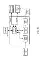
- System 10includes a firewall 12 and tap 14 disposed in communication with a communication line 16 .
- Communication line 16comprises an incoming communication line 18 and an outgoing communication line 20 , which are typically bundled in a single cable, such as an RJ-45 Ethernet cable.
- Firewall 12 and tap 14are generally placed in a strategic location between the other infrastructure of local area network 11 and Internet 15 .
- Communication line 16is connected to an intrusion detection system 22 and a dedicated network analyzer or other testing equipment 24 through tap 14 . That is, tap 14 includes couplers 26 , 28 or other components that enable intrusion detection system 22 and testing equipment 24 to be placed in communication with the data flow in communication line 16 .
- Tap 14may be configured to allow access to data transmitted over either a metallic conductive or an optical fiber communication line 16 as will be understood by those of skill in the art.
- network tapssuch as tap 14
- Conventional network tap 14does not permit devices connected thereto to transmit data onto communication line 16 .
- Network tapswere originally developed to enable testing equipment to access network data and it has generally been understood that network taps should not modify the data on communication line 14 and/or 16 or add data thereto.
- intrusion detection systemsWith the advent of intrusion detection systems, network taps began to be used to provide such intrusion detection systems with access to network data. However, because conventional network taps permit only unidirectional data flow to connected devices, intrusion detection systems have been configured to communicate with the firewall through an additional external, or out-of-band, communication line 30 .
- a switch 32e.g., an Ethernet switch
- This architectureenables intrusion detection system 22 to identify indicia of unauthorized access and to issue kill packets to firewall 12 to prevent additional unauthorized access. In fact, the intrusion detection system 22 can send any type of authorized packets through tap 14 to the firewall 12 and the LAN 11 as necessary.
- switch 32is often expensive. It would thus be an advantage to reduce the number of communication lines required to connect a communication line evaluation device, an intrusion detection system and/or firewall to a network. Furthermore, it would be an advantage to reduce the expense of having an extra switch to allow the intrusion detection system to communicate with the firewall.
- the present inventionis directed to network security taps for analyzing or monitoring one or more communication lines in a network system.
- the security tapsare configured to tap into a communication line that is connected to a firewall.
- the firewallfilters the data packets flowing therethrough to prohibit unwanted data packets from entering the network system. After being filtered by the firewall and processed by the security tap, the data enters into the network system through a network switch.
- the security tapsare configured to be connected to an intrusion detection system and, optionally, one or more testing equipment devices.
- the security tapincludes buffers or other devices to direct a copy of the network data to the attached devices, including the intrusion detection system and any testing equipment. Kill packets or other related data is permitted to be transmitted from the intrusion detection system to the firewall through the security tap.
- the security taptherefore includes a routing node configured to route the data flow from the intrusion detection system to the firewall. This capability is in contrast to conventional network taps, which permit only uni-directional data flow from the communication line to the attached devices.
- the routing nodeis an Ethernet switch that routes packets flowing through the security tap to their correct destinations.
- the Ethernet switchdirects data packets from the intrusion detection system to the firewall.
- the intrusion detection systemidentifies indicia of intrusive activity
- the intrusion detection systemsends a kill packet to the firewall via the security tap and the integrated Ethernet switch.
- the kill packetis routed by the Ethernet switch to the firewall.
- the firewallis programmed by the kill packet to prohibit any further intrusions by the intrusive source.
- the routing nodeis a Field Programmable Gate Array (FPGA).
- the FPGAcan be programmed to coordinate the flow of data in the security tap, similar to that performed by the Ethernet switch.
- the FPGAcontains a processing module which controls the process logic by which the FPGA controls the data flow therethrough.
- the FPGAincludes internal buffers that are used to coordinate the data flow. The buffers are used to avoid data collisions that might otherwise occur as data packets from the intrusion detection system are inserted onto the communication line that is in communication with the firewall. The FPGA buffers the data packets from the intrusion detection system until such time that they can be inserted onto the communication line without colliding with other data packets that are already on the network.
- the FPGAcan also be programmed to control other components of the security tap.
- the FPGAcan be connected to an external client device which enables the FPGA to be programmed by the network administrator or upgraded.
- the FPGAprovides integrated circuitry which enhances the functionality of the security tap.
- the network security taps of the inventionpermit the intrusion detection systems to communicate with the firewall directly through the taps. This is in contrast to conventional network taps that do not allow the backflow of data from attached devices to the communication that has been tapped.
- the network security taps of the inventioneliminate the need for the out-of-band communication link between the intrusion detection system and the firewall.
- FIG. 1illustrates a block diagram of a prior art system incorporating an intrusion detection system in communication with a firewall through an external communication line;
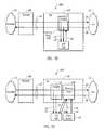
- FIG. 2Aillustrates a block diagram of an exemplary security tap according to one embodiment of the present invention
- FIG. 2Billustrates a block diagram of another embodiment of the security tap of the present invention
- FIG. 2Cillustrates a block diagram of yet another embodiment of the security tap of the present invention.
- FIG. 2Dillustrates a block diagram of still another embodiment of the security tap of the present invention.
- FIG. 2Eillustrates a block diagram of another embodiment of the security tap of the present invention.
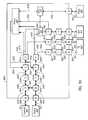
- FIG. 3illustrates a block diagram of a security tap of the present invention implementing an Ethernet switch to allow an intrusion detection system to send information into the security tap;
- FIG. 4Aillustrates a block diagram of the security tap of FIG. 3 , illustrating a microprocessor to control components of the security tap;
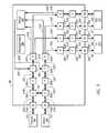
- FIG. 4Billustrates an exemplary hardware configuration for a security tap configured to connect to metal communication lines in accordance with an embodiment of the present invention
- FIG. 4Cillustrates an exemplary hardware configuration for a security tap configured to connect to optical fibers in accordance with an embodiment of the present invention
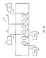
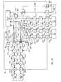
- FIG. 5Aillustrates a block diagram of a security tap of the present invention implementing an FPGA to allow an intrusion detection system to send information into the security tap;
- FIG. 5Billustrates a block diagram of the security tap of FIG. 5A , illustrating how the FPGA controls components of the security tap;
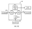
- FIG. 5Cillustrates a block diagram of the FPGA of FIG. 5A ;
- FIG. 5Dillustrates a flow diagram of the process logic steps for the FPGA of FIG. 5A ;
- FIG. 6Aillustrates a block diagram of a security tap of the present invention illustrating an FPGA to allow an intrusion detection system to send information into the security tap and illustrating a client device for upgrading the FPGA;
- FIG. 6Billustrates a block diagram of the security tap of FIG. 6A , illustrating how the FPGA controls other components of the security tap;
- FIG. 6Cillustrates a block diagram of the FPGA of FIG. 6A ;
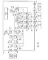
- FIG. 7Aillustrates a block diagram of a security tap of the present invention implementing an Ethernet switches to allow an intrusion detection system to send information into the security tap, a FPGA to control components of the security tap, and a second switch to streamline the data flow in the intrusion detection system;
- FIG. 7Billustrates a block diagram of the security tap of FIG. 7A illustrating how the FPGA controls other components of the security tap;
- FIG. 7Cillustrates a block diagram of signal formats for use in the security tap of FIG. 7A ;
- FIG. 7Dillustrates a block diagram of the FPGA of FIG. 7A ;
- FIG. 7Eillustrates a flow diagram of the process logic steps for the FPGA of FIG. 7A ;
- FIG. 8Aillustrates a block diagram of a security tap of the present invention implementing a switch which allows an intrusion detection system to send information into the security tap, an FPGA for controlling components of the security tap, and a second switch which combines both directions of data into one port for connecting to an intrusion detection system;
- FIG. 8Billustrates a block diagram of a security tap of the present invention implementing a switch which allows an intrusion detection system to send information into the security tap, an FPGA for controlling components of the security tap, and a second switch with a combined metallic conductor port for connecting to an intrusion detection system;
- FIG. 9Aillustrates a block diagram of a security tap of the present invention implementing a plurality of multiplexors, switches, and an FPGA for allowing the security tap to operate in a number of different modes;
- FIG. 9Billustrates a block diagram of the security tap of FIG. 9A illustrating how the FPGA controls other components of the security tap.
- the present inventionrelates to network security taps and associated systems incorporating various security features for monitoring and evaluating network data.
- the network security taps of the inventionpermit intrusion detection systems to access network data and to send kill packets (as well as other packets), as necessary, to the firewall and a local area network through the network security taps.
- FIGS. 2A through 2Eillustrate exemplary systems 100 A through 100 E incorporating security taps 110 A through 110 E that implement features of the present invention.
- the security tapsare illustrated in FIGS. 2A through 2E at a conceptual level, and the details of the circuitry of the security taps of the invention are disclosed hereinbelow in reference to FIGS. 3 through 9B .
- FIGS. 2A through 2Eare similar. As such, like elements are referred to with like reference numerals, using the letters A through E to distinguish the various embodiments.
- a detailed description of system 100 A in FIG. 2Awill be provided with the understanding that many of the details apply to the systems 100 B through 100 E. However, discussion will be provided, where necessary, where new reference numbers are introduced.
- system 100 Amay be implemented in communication systems comprising either conductive metal or optical fiber communication lines.
- System 100 Ais configured to analyze data carried by a main network cable 102 .
- network cable 102includes an incoming communication line 104 and an outgoing communication line 106 .
- the communication linesare full-duplex, which means they are “receive” and “transmit” at different times on the same physical lines.
- the terms “incoming” and “outgoing”, as used herein,are from the standpoint of the local area network 111 .
- Firewall 108filters the data packets that are transmitted on communication lines 104 and 106 , and controls the data that is permitted to pass between local area network 111 and Internet 115 . Because firewall 108 acts generally as a filter, certain unwanted data can pass therethrough until firewall 108 is programmed to filter that particular unwanted data. Firewall 108 acts in unison with an intrusion detection device to maximize its filtering capabilities to prevent unwanted intrusions, as will be discussed further below.
- Network cable 102is also connected to a security tap 110 A.
- Security tap 110 Ais configured with a pair of dedicated couplers 112 , 114 . Couplers 112 and 114 allow an intrusion detection system 116 and a testing equipment 118 to be connected to security tap 110 A. Couplers 112 and 114 are configured to enable a portion of the energy of the data signal of network cable 102 to be tapped and transmitted to intrusion detection system 116 and/or testing equipment 118 . In some cases, the energy of the signal is not decreased at all; rather, it is increased, because it is regenerated within the security tap 110 A. Intrusion detection system 116 and testing equipment 118 are some examples of “attached devices” that may be connected to security tap 110 A.
- an “attached device”may be any equipment which is selectively connectable to security tap 110 A to be allowed to communicate with security tap 110 A.
- an “attached device”may be any equipment which is selectively connectable to security tap 110 A to be allowed to communicate with security tap 110 A.
- the intrusion detection system 116is connected to security tap 110 A via a communication line 124 that carries a representation of the signal that is transmitted on communication line 104 .
- the intrusion detection systemis also connected to security tap 110 A by a communication line 126 that carries a representation of the signal that is transmitted on communication line 106 .
- a communication line 128 from intrusion detection system 116is coupled to outgoing communication line 106 .
- Communication line 128conveys information from intrusion detection system 116 to communication line 106 . That is, security tap 110 A is configured to allow intrusion detection system 116 to send information into the security tap, whereas conventional taps do not allow such functionality.
- coupler 112is configured with a routing node 129 A positioned at the node where communication lines 106 , 126 and 128 intersect.
- routing noderefers to a component of the network security tap that permits data packets from the intrusion detection system or other attached data devices to be inserted into the main communication cable so that the data packets can be transmitted to a firewall or another designated network location.
- the routing nodeis positioned at the intersection of the main communication cable and the communication line from one or more attached devices.
- the routing nodecan include any component that permits data packets from the intrusion detection system to be inserted onto the main communication cable without modifying or being intrusive with respect to the data that is otherwise transmitted thereon.
- routing nodesexamples include the Ethernet switches and the Field Programmable Gate Arrays (FPGAs) disclosed herein. It is noted that the term “routing node” does not necessarily connote a conventional router or the function of a conventional router, but is instead a general term intended to encompass any suitable component that can control the placement or insertion of data packets from the intrusion detection system or other attached data device as set forth above.
- FPGAsField Programmable Gate Arrays
- Routing node 129 Acontrols the flow of data packets sent from intrusion detection system over communication line 128 to communication line 106 .
- Routing node 129 Amay be implemented in embodiments having either metallic conductive wires or optical fibers. In the embodiment of FIG. 2A , routing node 129 A has a limited function of directing the flow of information over the junction of communication line 106 and communication line 128 without disrupting the other data packets carried on communication lines associated with system 10 A. The operation of routing node 129 A will be described in more detail below.
- Test equipment 118is connected to security tap 110 A via communication lines 130 , 132 that carry a representation of the signal that is transmitted on communication lines 106 and 104 , respectively.
- the information from communication lines 130 , 132is sent to testing equipment 118 for analysis.
- testing equipment 118can be any network analyzer or other device that requires non-intrusive access to the network data.
- the testing equipment 118can obtain and display statistics associated with the network data; can analyze the type of data in network cable 102 , the integrity of the communication flow in network cable 102 , or interruptions in network communication; can search for specific patterns, detects errors, etc.
- communication lines 130 , 132 connecting testing equipment 118 with security tap 110 Aare configured to allow uni-directional data flow. That is, testing equipment 118 generally only receives data. However, it will be appreciated that embodiments where testing equipment 118 transmits data into security tap 110 A are contemplated.
- Intrusion detection system 116monitors the traffic on network cable 102 and determines whether there are indicia indicating that an attempt to breach the security associate with local area network 111 is being made.
- intrusion detection system 116is programmed with various algorithms that enable it to detect certain intrusive activity. For example, intrusion detection system 116 may compare the source material and compare the signatures to a database of known attack signatures, compare the traffic load to a baseline traffic load, raising a warning if the traffic load exceeds the baseline to indicate increased activity in the communication line, or detect for anomalies in the data flow, for network attacks, hacking, and the like.
- the network security taps of the inventioncan be used or adapted for use with substantially any conventional intrusion detection system or other intrusion detection systems that will be developed in the future.
- intrusion detection system 116sends a command in the form of one or more data packets (referred herein as “kill packets”) through communication line 128 , which are directed by routing node 129 A into outgoing communication line 106 to firewall 108 .
- the security tap 110 Amay also be configured to route the kill packets or other related data packets to other nodes in the local area network 111 .
- the data packetsinstruct (i.e., reprogram) firewall 108 to place a filter on a specific IP address that appears to be associated with the potential intrusion. That is, the data packets sent from intrusion detection system 116 reprogram firewall 108 to prevent further passage of information coming from the suspected intrusive source.
- Intrusion detection system 116may also maintain a log of activity of the network on which security tap 110 A is placed. System 100 A thus provides a dynamic, learning network security system.
- routing node 129 Aallows limited information to be transmitted into communication line 102 from intrusion detection system 116 , thereby greatly enhancing the ability of an intrusion detection system to operate in an integrated manner in a network.
- security tap 110 Ais largely a passive device, generally remaining idle until an indication of unwanted intrusion is detected. Only then does the intrusion detection system 116 send information to communication line 102 . With coupler 112 incorporating the routing node 129 A, data collisions can be avoided in communication line 102 , ensuring that data is not lost and is efficiently sent from both outgoing communication line 106 and intrusion detection system 116 .
- the security taps of the present inventionthus provide added security features without compromising the integrity of the system.
- security taps of the present inventionare non-intrusive, allowing the security tap to continue to analyze network communications without interrupting the flow of traffic on communication line 102 . It will be appreciated that security tap 110 A may be configured to monitor and analyze multiple communication channels.
- FIG. 2Billustrates a second embodiment of a system 100 B incorporating a security tap 110 B.
- routing node 129 Bis disposed over the node at the intersection of all of the communication lines associated with coupler 112 . That is, routing node 129 B is in communication with communication lines 104 , 106 , 124 , 126 and 128 . Routing node 129 B functions to control the flow of data packets between communication line 106 and communication line 128 . In addition, because routing node 129 B is disposed over the other communication lines, routing node 129 B can be programmed to control, modify, or analyze the data of any communication line within security tap 110 B. Details regarding this embodiment are disclosed below in reference to FIGS. 3 and 5A .
- FIG. 2Balso illustrates that testing equipment 118 is not necessary in order to practice features of the present invention.
- system 100 Bcomprises a security tap 110 B that is connected to an intrusion detection system 116 but not additional testing equipment.
- security tap 110 Bmay be to facilitate the use of an intrusion detection system, without other functionality.
- FIG. 2Cillustrates another embodiment of system 100 C comprising a security tap 110 C.
- coupler 112is distinct from routing node 129 C.
- Routing node 129 Cis positioned at the node of the intersection of 104 , 106 and 128 .
- Routing node 129 Cimplements functionality to control the flow of data between communication line 106 and communication line 128 .
- routing node 129 Chas access to the flow of data in communication line 104 .
- the functions of routing node 129 Cmay control, modify, or analyze the data on other junctions in security tap 110 C. It will be appreciated that this additional circuitry within security tap 110 C allows security tap 110 C to have additional functionality not available in prior art taps, including the native ability to perform some analysis of network data and reporting of statistics associated with the network data.
- FIG. 2Dillustrates an embodiment of a system 100 D with a security tap 110 D.
- security tap 110 Dincorporates intrusion detection system 116 as an integrated hardware. That is, communication lines 124 , 126 and 128 are not external of security tap 110 D. While this embodiment is similar to the embodiment of security tap shown in FIG. 2B , it will be appreciated that such an embodiment may also operate according to the embodiments illustrated in FIG. 2A or 2 C.
- security tap 110 Ddispenses with additional connections and hardware, requiring only ports to connect security tap 110 D to main communication line 102 .
- routing node 129 Dmay be programmed to have other functionality for controlling, modifying or analyzing data flow in communication lines 102 , 124 , 126 and 128 .
- the security tap and the intrusion detection systemare integrated into a single device. Integration in this manner may decrease the flexibility of both the security tap and the intrusion detection system, but may also simplify the use and installation of the intrusion detection system.
- FIG. 2Eillustrates a system 100 E incorporating another embodiment of security tap 10 E.
- security tap 110 Ecomprises a separate coupler 112 and routing node 129 E, similar to that shown in FIG. 2 C.
- Intrusion detection system 116is connected to routing node 129 E through communication line 128 .
- Communication line 128is coupled to outgoing communication line 106 to allow information to be sent to firewall 108 .
- another communication line 131connects intrusion detection system 116 to routing node 129 E.
- Communication line 131is coupled to incoming communication line 104 .
- routing node 129 Eis able to transmit information from intrusion detection system 116 to other nodes of the local area network 111 .
- Routing node 129 Eis also connected to a client device 134 through a communication line 138 and 140 .
- routing node 129 Eis programmable to allow security tap 110 E to control, modify, or analyze data flow in communication line 102 .
- Client device 134may be any hardware device having an application thereon that allows a user to program routing node 129 E.
- client device 134may be a personal computer, a laptop computer, a hand-held personal data assistant (PDA), a cellular telephone, a notepad, a dedicated programming device designed specifically for programming the routing node 129 E, and the like.
- PDApersonal data assistant
- routing node 129 Ecan be programmed with additional functionality.
- security tap 110 Ecan be used as a network analyzer or a jammer. It will be appreciated that any of the embodiments of security tap 110 illustrated in FIGS. 2A through 2D may be modified to connect to an external client device 134 to upgrade or program the routing node 129 .
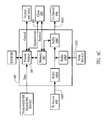
- a security tap 300is shown incorporating a routing node.
- the routing nodeis an Ethernet switch 302 .
- Security tap 300also incorporates a microprocessor 336 , which may be a programmable integrated circuit (PIC), which is a single-chip microcontroller. Alternatively, the microprocessor can be a field a, programmable gate array (FPGA).
- Switch 302is configured to direct data packets flowing through security tap 300 , routing the data packets to their correct destination.
- Microprocessor 336is configured to control switch 302 and other components of security tap 300 as will be discussed in more detail below.
- Security tap 300is configured to tap data carried by primary communication lines or a network cable, represented in FIG. 3 by communication lines 314 , 316 .
- Security tap 300is configured with ports 304 A, 304 B, which enable security tap 300 to be connected to the primary communication lines using, for example, RJ-45 connectors.
- a firewall 306 and network switch 308are in communication with the primary communication lines 314 , 316 , respectively.
- informationflows through the main communication lines 314 and 316 from the Internet, through firewall 306 , then through security tap 300 , and finally to switch 308 , which directs the data packets to the appropriate destinations in the local area network, and the data also can flow in the reverse direction from the local area network to the Internet.
- Security tap 300also includes ports 304 C through 304 F that enable security tap 300 to be connected to testing equipment 310 and an intrusion detection system 312 , through communication lines 318 , 320 , 322 , 324 , respectively.
- Various commercially-available intrusion detection devicesexist, substantially any of which can be used with the security taps of the invention.
- substantially any testing equipment that require non-intrusive access to network datacan be used with the security taps of the invention.
- Ports 304 A through 304 Fmay be any port configuration that provides a suitable communication line connection to security tap 300 .
- ports 304 A through 304 Fmay be RJ-45 connections.
- RJ-45 connectionscan be configured for connection to Ethernet cables.
- the label “RJ”is used to represent an RJ-45 connection. Because RJ-45 cables support full duplex communication, a pair of RJ-45 ports connects the main communication line, represented by numerals 314 and 316 , to the security tap.
- security tap 300may use two connectors to connect with the firewall 306 and two additional connectors to connect with the switch 308 .
- ports 304 A through 304 Fmay be modified to have a “transmit” port and a “receive” port to allow the communication line to be connected thereto.
- the type of connection for ports 304 A through 304 Fmay be configured depending on design requirements.
- the main communication cablecan be viewed as a first segment 314 and a second segment 316 which allows uninterrupted bi-directional data flow between firewall 306 and switch 308 .
- first segment 314 and second segment 316must be physically severed to allow network tap 300 to be disposed therebetween.
- first segment 314 and second segment 316are connected to network tap 300 , a complete data circuit is formed, re-establishing the uninterrupted, bi-directional data flow between firewall 306 and switch 308 .
- Ports 304 A and 304 Benable the connection of first segment 314 and second segment 316 of the main communication cable to security tap 300 , respectively.
- FIG. 4Billustrates an exemplary hardware configuration for connecting a metallic conductive wire communication line to security tap 300 . That is, port 304 A is connected to firewall 306 through communication line 314 and port 304 B is connected to switch 308 through communication line 316 . In addition, ports 304 C, 304 D are connected to testing equipment 310 through communication lines 318 , 320 , and ports 304 E, 304 F are connected to intrusion detection system 312 via ports 322 , 324 . Note that ports 304 C, 304 D, 304 E allow uni-directional data flow while port 304 F allows bi-directional data flow.
- FIG. 4Cillustrates an exemplary hardware configuration for connecting an optical fiber communication line to security tap 300 .
- port 304 Ais modified to have an IN or “transmit” port and an OUT or “receive” port which connects to firewall 306 through communication line 314 .
- communication line 314is represented by two optical fibers, one representing ingoing data flow, the other representing outgoing data flow.
- Port 304 Bis modified to have an IN port and an OUT port which connects to firewall 308 through communication line 316 (again, with communication line 316 being represented by distinct optical fibers).
- Ports 304 C, 304 Dare modified to have two OUT ports which allow for uni-directional data flow to testing equipment 310 .
- Ports 304 E, 304 Fare modified to connect to intrusion detection system 312 , with port 304 E allowing uni-directional data flow and port 304 F allowing bi-directional data flow.
- ports 304 A, 304 Bare connected to relays 326 A, 326 B via communication lines 314 A, 316 A, respectively.
- Relays 326 A, 326 Bsend the information to transformers 328 A, 328 B through communication lines 314 B, 316 B, respectively. If there is no system power at the security tap, relays 326 A, 326 B transmit the data directly to each other via communication link 334 . Thus, the data link through the security tap is operational even if the power supply is lost or disabled.
- transformers 328 A, 328 Bprovide the isolation and common mode filtering required to support category 5 UTP cables for use in Ethernet 10/100/1000Base-T duplex applications.
- Informationflows from transformers 328 A, 328 B to physical layer devices 330 A, 330 B through communication lines 314 C, 316 C, respectively.
- Physical layer devices (“PHYs”) 330 A, 330 Bconvert the electrical signals into a desired format which is compatible with the signal's intended destination.
- PHYsPhysical layer devices
- physical layer devices 330 A, 330 Bconvert the signal to a format which is compatible with switch 302 .
- the data from physical layer devices 330 A, 330 Bare sent to fan out buffers 332 A, 332 B by communication lines 314 D, 316 D, respectively.
- Fan out buffers 332 A, 332 Benable the data packets to be duplicated and sent to multiple destinations.
- Fan out buffer 332 Asends data packets to switch 302 and physical layer devices 330 D, 330 F through communication lines 314 E, 314 F, 314 G, respectively.
- fan out buffer 332 Bsends data packets to switch 302 and physical layer devices 330 C, 330 E through communication lines 316 E, 316 F, 316 G, respectively.
- Communication lines 324 E, 324 Dconnect switch 302 to physical layer devices 330 B, 330 A, respectively.
- firewall 306flows through the path formed by communication lines 314 A, 314 B, 314 C, 314 D, 314 E, 324 E, 316 C, 316 B and 316 A.
- Ethernet switch 308flows through the path formed by communication lines 316 A, 316 B, 316 C, 316 D, 316 E, 324 D, 314 C, 314 B and 314 A.
- Physical layer devices 330 C through 330 Fare connected to transformers 328 C through 328 F by communication lines 316 H, 314 H, 316 J, 324 B, respectively.
- Transformers 328 C through 328 Fare, in turn, are connected to ports 304 C through 304 F through communication lines 3161 , 3141 , 316 K, 324 A, respectively.
- Testing equipment 310is connected to ports 304 C, 304 D by communication lines 318 , 320 , respectively.
- intrusion detection system 312is connected to ports 304 E, 304 F by communication lines 322 , 324 , respectively.
- physical layer device 330 Fis connected to switch 302 via communication line 324 C.
- physical layer devicesmay be a transceiver such as the Alaska® Quad Gigabit Ethernet Transceiver manufactured by Marvell located in Sunnyvale, Calif.
- communication lines 314 , 316 and 324allow bi-directional data flow therethrough.
- communication lines 314 A, 314 B, 314 C, 316 A, 316 B, 316 C, 324 A and 324 Ballow bi-directional data flow therethrough.
- These bi-directional communication linesare illustrated in FIG. 3 with a single line, although physically these lines are embodied using several pairs of conductors.
- communication lines 318 , 320 and 322allow uni-directional data flow therethrough.
- communication lines 314 D through 3141 , 316 D through 316 K, 324 C, 324 D and 324 Ealso allow uni-directional data flow therethrough.
- bi-directional data flowis indicated by a double-headed arrow while uni-directional data flow is indicated by a single-headed arrow.
- the signal on which the data packets are encodedis split or duplicated so that a representation of the data flowing between firewall 306 and Ethernet switch 308 can be sent to testing equipment 310 and intrusion detection system 312 to be monitored. That is, data packets are sent from fan out buffers 332 A, 332 B to physical layer devices 330 C through 330 F. These data packets are sent to testing equipment 310 and intrusion detection system 312 . Data packets from fan out buffers 332 A, 332 B are also sent to switch 302 .
- port 304 Fallows bi-directional flow of data therethrough.
- switch 302is an Ethernet switch
- port 304 Fis configured to accept Ethernet traffic generated by intrusion detection system 312 .
- Port 304 Fis thus configured to receive various types of device data from the attached device, intrusion detection system 312 .
- Device datamay be instructions from the attached device, messages to be sent to other components of the network, or, in this particular application, a control signal in the form of one or more kill packets.
- intrusion detection system 312identifies intrusive activity, it sends a kill packet through port 304 F to transformer 328 F and to physical layer device 330 F.
- the kill packetis sent from physical layer device 330 F through communication line 324 C to switch 302 .
- the kill packetcontains header information such that Ethernet switch 302 directs the data packet to firewall 306 . That is, the kill packet is sent via communication line 324 D to physical layer device 330 A which is in the data flow path of firewall 306 .
- the kill packet sent from intrusion detection system 312instructs firewall 310 to prohibit further data flow from the intrusive source.
- the kill packetcan also be addressed to another network node in the local area network, in which case, switch 302 also directs the kill packet to the other designated node.
- another kill packetis sent to switch 308 to prevent further intrusions through the other network node into the local area network.
- This second kill packetcan be sent at substantially the same time as the first kill packet so that both ends of the main communication cable are protected from the intrusion.
- Ethernet switch 302represents a hub for data packets coming from firewall 306 , switch 308 and intrusion detection system 312 .
- Ethernet switch 302examines the destination address in the header of each data packet and sends the data packet to the corresponding port.
- Ethernet switch 302prevents the collision of data by coordinating data flow therethrough.
- a suitable Ethernet switchis the Scalable 12-Port Gigabit Ethernet MultiLayer Switch manufactured by Broadcom located in Irvine, Calif. Because switch 302 is connected to both physical layer devices 330 A, 330 B by communication lines 324 E, 324 D, information may be sent from intrusion detection system 312 to switch 308 . This may be desirable, for example, where intrusion detection system 312 sends information regarding the intrusive source to be logged in the network system.
- FIG. 4Adepicts security tap 300 and a configuration for controlling components of the security tap.
- Microprocessor 336is configured to control switch 302 , physical layer devices 330 A through 330 F, and relays 326 A, 326 B as indicated by control lines 338 A through 3381 .
- Microprocessor 336may comprise a microchip with integrated circuitry configured to control these components.
- microprocessor 336is configured to control the ability of switch 302 to allow incoming data from intrusion detection system 312 . Essentially, this provides security tap 300 with an “enable” or “disable” mode—in the “enable” mode, backflow data from intrusion detection system 312 is allowed; in the “disable” mode, switch 302 does not accept data transmissions from intrusion detection system 312 .
- security tap 300may include a manual switch or another user interface for enabling a user to enable/disable the bi-directional communication between security tap 300 and intrusion detection system 312 . This may be advantageous, for example, where the user desires to substitute the intrusion detection system with other testing equipment.
- the enable/disable featuremay be applied to any embodiment disclosed herein. The enable/disable feature is further discussed in detail with respect to FIG. 9 A.
- the microprocessor 336may be configured to control other components of security tap 300 other than those illustrated in FIG. 4 A.
- signals between ports 304 A through 304 G and physical layer devices 330 A through 330 Gmay be transmitted in Media Dependent Interface (MDI) format.
- MDIMedia Dependent Interface
- Signals between one physical layer devices to another physical layer devicemay be transmitted in Serial Gigabit Media Independent Interface (SGMII) format which consist of serial 1.25 GHz encoding.
- microprocessor 336may communicate with physical layer devices 330 A through 330 F using SGMII format.
- SGMIISerial Gigabit Media Independent Interface
- FIG. 5Aillustrates a security tap 400 incorporating an alternative routing node.
- the routing nodeis a Field Programmable Gate Array (FPGA) 440 .
- An FPGAis an integrated circuit which is controlled using programmable code.
- FPGA 440can be programmed to coordinate the flow of data from an intrusion detection system 412 to a firewall 406 .
- Many of the elements in FIG. 5Aare similar to the elements in FIG. 3 . As such, like elements are referred to with like reference numerals, substituting 300 's for 400 's. Thus, a detailed description of security tap 400 will not be provided, except where new reference numbers are introduced.
- FPGA 440now acts as the router for data flow between firewall 406 , Ethernet switch 408 , testing equipment 410 and intrusion detection system 412 .
- FPGA 440is connected to a plurality of physical layer devices 430 G through 430 J through communication lines 442 A through 442 D, respectively.
- FPGA 440provides circuitry which can be preprogrammed to perform certain functions.
- FPGA 440can be programmed by an external source after the security tap 400 has been deployed in a network.
- datais allowed to flow in a continuous circuit between firewall 406 and Ethernet switch 408 through FPGA 440 .
- intrusion detection system 412is able to send data packets through FPGA 440 , which can then be directed to firewall 406 or other components of security tap 400 without the data colliding with other data flowing through FPGA 440 .
- FPGA 440in addition to controlling the flow of data therethrough, FPGA 440 also controls physical layer devices 430 A through 430 J and relays 426 A, 426 B. Control lines 444 A through 444 L indicate the connection between FPGA 440 and each of these respective components.
- FIG. 5Cillustrates FPGA 440 in more detail. As shown in FIG. 5C , FPGA 440 is disposed over the junction between communication line 442 D containing outgoing information from switch 408 and communication line 424 C containing outgoing information from intrusion detection system 412 . FIG. 5C only depicts the situation in which information from switch 408 and intrusion detection system 412 may possibly collide. However, as discussed above, FPGA 440 is programmed to route information between firewall 406 , switch 408 , testing equipment 410 and intrusion detection system 412 .
- FPGA 440comprises processing module 445 that is programmed to coordinate the flow of data packets in FPGA 440 .
- FPGA 440includes buffers 446 A, 446 B, 446 C disposed in communication with communication lines 442 D, 424 C, 442 C, respectively.
- Buffers 446 A, 446 B, 446 Care configured with cache memories that retain data packets according to the logic in processing module 445 .
- Processing module 445is programmed with basic logic that coordinates the flow of data packets between buffers 446 A, 446 B, 446 C.
- process logic 445is programmed to control physical layer devices and relays in security tap 400 .
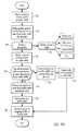
- FIG. 5Dillustrates a flow diagram 500 of one example of the process logic steps that can be programmed in FPGA 440 .
- the flow diagram of FIG. 5Dillustrates one example of a method of determining when a data packet received from the intrusion detection system and stored in buffer 446 B can be safely inserted into the flow of data on the communication line that is connected with the firewall without resulting in corruption of the data otherwise carried on the communication line.
- the basic criterionis that a data packet (e.g., a kill packet) can be inserted into the data flow at an idle time in the data flow or when only idle data packets are otherwise transmitted on the communication line.
- FPGA 440detects the presence of one or more data packets stored in buffer 446 A.
- FPGA 440extracts one packet at a time from buffer 446 A for analysis.
- FPGA 440goes through a simple packet analysis, obtaining various statistics relating to the packet. Such statistics may include whether or not the packet is idle, the packet size, CRC errors in the packet, the priority level of the packet, and the like.
- FPGA 440updates a statistics table which is maintained on all of the packets flowing through FPGA 440 .
- FPGA 440detects the presence of one or more packets stored in buffer 446 B. In addition, FPGA 440 analyzes the one or more packets for idle packets. While not shown, FPGA 440 may also do a packet analysis on packets stored in buffer 446 B. At step 512 , FPGA 440 determines whether enough idle packets have passed through buffer 446 A to allow data packets from buffer 446 B to be inserted into communication line 442 D. At step 514 , if there are enough idle packets to insert data packets from buffer 446 B, FPGA 440 extracts one packet at a time from buffer 446 B and discards or overwrites the idle packet. At step 520 , FPGA 440 shifts the packet into buffer 446 C. At step 522 , FPGA 440 transmits the packet into outgoing traffic directed to firewall 406 . Thus, intrusion detection system 412 is allowed to transmit information through security tap 400 .
- buffer 446 Bstores the data packets from intrusion detection system 412 until enough idles are determined by step 512 .
- FPGA 440prepares the idle and/or data packet to be transmitted to buffer 446 C. That is, FPGA 440 waits until the entire packet is loaded and ready.
- the packetis transmitted to outgoing traffic directed to firewall 406 .
- the foregoingis merely one example of an exemplary process logic that FPGA 440 could be programmed to perform. Other process logic steps may be used depending on design considerations.
- the data packets stored in buffer 446 Aare analyzed only when it is first determined that there is a data packet in buffer 446 B that needs to be inserted into the data flow on the communication line.
- the presence of a data packet in buffer 446 Bis quite infrequent, since these data packets are typically kill packets that are generated in response to a determination that an intrusion may be underway.
- FIG. 6Aanother embodiment of a security tap 600 is illustrated. Many of the elements in FIG. 6A are similar to the elements in FIG. 5 A. As such, like elements are referred to with like reference numerals, substituting 600 's for 400 's. Thus, a detailed description of security tap 600 will not be provided, except where new reference numbers are introduced.
- security tap 600has a connection between FPGA 640 and a client device 650 .
- Client device 650may be any suitable programming device as described above.
- client device 650connects to a port 604 G through communication line 652 .
- Port 604 Gconnects to transformer 628 G via communication line 652 A.
- Transformer 628 Gconnects to a physical layer device 630 K via a communication line 652 B.
- FPGA 640operates to coordinate the flow of data from intrusion detection system 612 to firewall 606 and/or other components of security tap 600 . Because the elements between FIGS. 5A and 6A are similar, the process logic for the FPGA discussed with respect to FIG. 5C also applies to FPGA 640 . That is, the steps that FPGA 640 uses to coordinate the flow of data packets between intrusion detection system 610 and firewall 608 may be similar to the steps illustrates and discussed with respect to FIG. 5 C. Alternatively, other process logic flow may be used to produce the same functionality. In addition, as depicted in FIG. 6B , FPGA 640 controls the operation of physical layer devices 630 A- 630 K and relays 326 A, 326 B as indicated by control lines 654 A- 654 M.
- FPGA 640is allowed receive and transmit communication through an external source, client device 650 .
- Client device 650comprises client software which allows a user to program FPGA 640 externally.
- FPGA 640may thus be programmed to control physical layer devices, relays, or other components of security tap 600 .
- FPGA 640may be programmed to add or alter functionality of the FPGA.
- FPGA 640can be programmed to collects certain statistical information on the data flow in security tap 600 and to transmit those statistics to client device 650 .
- Port 604 Gmay thus be properly termed a “management port.”
- the client device 650can be either local with respect to security tap 600 or can be remote, with communication being established using the Internet or a private network. Client device 650 allows FPGA 640 to be reprogrammed at the location where security tap 600 is connected to the network instead of having to disconnect security tap 600 from the network to reprogram or replace the security tap. Those skilled in the art will recognize that client device 650 will give security tap 600 an IP address for purposes of network configurations. Where prior art taps were not detectable by network monitoring devices, some embodiments of security taps of the present invention will be recognizable.
- FPGA 640comprises a process module 645 that is programmed to operate FPGA 640 .
- FPGAalso comprises buffers 646 A, 646 B, 646 C that coordinate the flow of data from intrusion detection system 612 to firewall 606 .
- FPGA 640operates to coordinate the flow of data therethrough.
- Buffers 646 A, 646 B and 646 Coperate in conjunction with process module 645 in a manner that is substantially similar to that described with reference to FIG. 5 C.
- FPGA 640comprises a memory 647 .
- Process module 645 , memory 647 and buffer 646operate together to extract data from the security tap 600 and deliver information to client device 650 upon request. That is, information enters FPGA 640 from firewall 606 , switch 608 and intrusion detection system 612 .
- Process module 645analyzes the data and saves relevant statistics regarding the data in memory 647 .
- statistics saved in memory 647are transmitted to buffer 646 C and delivered to client device 650 .
- FIG. 6Calso illustrates that FPGA 640 controls components of security tap 600 .
- process module 645is connected to physical layer devices and relays to control these elements.
- FPGA 640is connected to client device 650 in such a way that allows process module 645 to be reprogrammed by an external user. This may be advantageous where a user desires FPGA 640 to have additional functionality than it previously had. Alternatively, client device 650 may delete or alter current functions of FPGA 640 .
- FIG. 7Aan alternative embodiment of a security tap 700 is illustrated. Many of the elements in FIG. 7A are similar to the elements in FIGS. 4A , 5 A and 6 A. As such, like elements are referred to with like reference numerals, substituting 700 's for 300 's, 400 's and 600 's. Thus, a detailed description of security tap 700 will not be provided, except where new reference numbers are introduced.
- the routing nodeis an Ethernet switch 702 .
- security tap 700incorporates a combination of FPGAs and Ethernet switches to provide additional functionality.
- a switch 702is connected to fan out buffers 732 A, 732 B and physical layer devices 730 A, 730 B, 730 F.
- switch 702functions to coordinate the data flow between firewall 706 , switch 708 and intrusion detection system 712 .
- switch 702may be configured to collect some information on the data flowing through switch 702 .
- security tap 700comprises a second Ethernet switch 756 .
- Switch 756is disposed between fan out buffers 732 A, 732 B and physical layer device 730 E. Communication lines 714 F, 716 F from fan out buffers 732 A, 732 B are connected to switch 756 .
- Switch 756is connected to physical layer device 730 E through communication line 758 .
- Switch 756contains ports that allows communication lines 714 F, 716 F to be integrated into a single communication line 758 .
- switch 756combines the data flow from both communication lines 714 F, 716 F into a single signal which is delivered by communication line 758 and ultimately to port 704 E to intrusion detection system 712 .
- Port 704 Eis configured to receive only outgoing information from security tap 700 .
- port 704 Fis configured to receive only incoming information from intrusion detection system 712 .
- ports 704 E, 704 Fare configured to receive uni-directional flow of data.
- port 304 Eis configured to receive uni-directional data flow while port 304 F is configured for bi-directional data flow.
- the sole function of port 704 Eis to access network data from security tap 700 .
- port 704 Fis a control signal port, whose sole function is to receive control signals in the form of kill data packets from the data device, the intrusion detection system.
- the factors for deciding whether to use security tap 700 of FIG. 7A or security tap 300 of FIG. 3include the configuration of the corresponding connectors of the intrusion detection system.
- switches 702 , 756may be the same switch.
- Broadcomprovides the hardware required to implement all of the required connections.
- security tap 700comprises an FPGA 760 that is connected to switches 702 , 756 through communication lines 762 , 764 , respectively.
- FPGA 760is also connected to client device 750 in much the same manner as in FIG. 6 A. Accordingly, the connection between FPGA 760 and client device 750 will not be discussed in detail.
- the connection between FPGA 760 and client device 750allows FPGA to be programmed with additional features.
- FPGA 760is configured to extract statistical information from switch 702 through communication line 762 .
- FPGA 760is also configured to control components of security tap 700 . With reference to FIG. 7B , FPGA 760 controls switches 702 , 756 , physical layer devices 730 A through 730 G and relays 726 A, 726 B as indicated by control lines 766 A through 766 K.
- signals between ports 704 A through 704 G and physical layer devices 730 A through 730 Gmay be transmitted in Media Dependent Interface (MDI) format. This is represented by the double-lined arrows in FIG. 7 C. Signals between one physical layer devices to another physical layer device may be transmitted in Serial Gigabit Media Independent Interface (SGMII) format which consist of serial 1.25 GHz encoding. This is indicated in FIG. 7C by single-lined arrows. The exception to this may be signals coming to and from FPGA 760 , which may communicate with switches 702 , 756 using a PCI bus, SPI communication or I 2 C serial communication format. This is represented in FIG. 7C by dashed-lined arrows. Those skilled in the art will recognize that other configurations may be used depending on design considerations.
- MDIMedia Dependent Interface
- SGMIISerial Gigabit Media Independent Interface
- Security tap 700thus provides a number of features.
- switch 702allows data from intrusion detection system 712 to be sent to firewall 706 without disrupting data flow through security tap 700 .
- switch 702can collect some statistical information about the data flowing therethrough. This statistical information can be retrieved by FPGA 760 and sent to client device 750 .
- switch 756simplifies the types of ports and connections that are required, allowing port 704 F to have unidirectional data flow instead of bi-directional data flow.
- FPGA 760provides for control of components of security tap 700 .
- FPGA 760can be programmed by an external source (i.e., client device 750 ) to perform other functions.
- FPGA 760comprises process module 745 , memory 747 , and buffers 768 A, 768 B. Information from switch 702 is sent to buffer 768 A in FPGA 760 . The buffered information is then analyzed by process module 745 . Certain statistics may be stored in memory 747 . Upon request by client device 750 , these statistics can be transferred to buffer 768 B and then transmitted to client 750 .
- FPGA 760also provides for the control of components of security tap 760 . As shown in FIG. 7D , process module 745 can be connected to physical layer devices, relays, and switches to control their operation. In addition, the connection between FPGA 760 and client device 650 allows FPGA 760 to be reprogrammed by an external user.
- FIG. 7Eillustrates a process logic flow diagram for FPGA 760 in one embodiment where FPGA 760 functions as a statistical collector.
- incoming data from switch 702is stored in buffer 768 A.
- process module 745analyzes the data, depending on the type of predetermined statistics a user desires. For example, process module 745 may determine the packet size, existence of CRC errors, priority level and the like.
- process module 745may update a statistics table stored in memory 747 .
- the data analysisis stored in the local memory 747 .
- FPGA 760may then do a number of things with the data stored in local memory 747 .
- FPGA 760can respond to a request from client device 750 .
- client device 750requests data from FPGA 760 .
- process module 745processes the request and writes the requested data into buffer 768 B.
- process module 745sends the requested data in buffer 768 B to client device 750 .
- FPGA 760may also use the data stored in local memory 747 to enable it to control switches, physical layer devices, or relays.
- process module 745accesses the data stored in local memory 747 to instruct it how to control or operate switches 702 , 756 or other components of FPGA 760 .
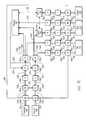
- FIG. 8Aillustrates another embodiment of a security tap 800 A.
- Many of the elements in FIG. 8Aare similar to the elements in FIG. 7 A. As such, like elements are referred to with like reference numerals, substituting 800 's for 700 's. Thus, a detailed description of security tap 800 A will not be provided, except where new reference numbers are introduced.
- FIG. 8Aprovides an alternative configuration for connecting security tap 800 A to intrusion detection system 812 so that only a single connecting cable is required. That is, intrusion detection system 812 is connected to security tap 800 A via port 804 E. Intrusion detection system 812 is connected to port 804 E by communication line 870 , which is shown as a single cable. Communication line 870 thus provides for bi-directional (i.e., full-duplex) transmissions. This embodiment can be used for those intrusion detection system that require full-duplex transmission connections. This embodiment enables intrusion detection system 812 to omit a switch which the previous embodiments required in order to route the flow of data from port 304 E and 304 F to the intrusion detection system.
- a switch 856combines the data flow of communication lines 814 F and 816 F into one outgoing communication line 858 .
- Physical layer device 830 Eis configured to receive the data flow from communication line 858 .
- physical layer device 830 Eis connected to switch 802 through communication line 870 C to deliver data thereto.
- Physical layer device 830 Ealso connects to transformer 828 E through communication line 870 B, which, in turn, is connected to port 804 E through communication line 870 A.
- Transformer 828 E and port 804 Eare configured to allow bi-directional flow of communication therethrough.
- only a single port 804 Eis required to connect intrusion detection system 812 to security tap 800 A.
- the embodiment of FIG. 8Adispenses with dual ports required to connect intrusion detection system 812 to security tap 800 A.
- FIG. 8Aprovides an alternative embodiment for the connection between FPGA 860 and client device 850 .
- Port 804 Gcomprises an XportTM Embedded Device Server manufactured by Lantronix® located in Irvine, Calif. XportTM can communicate with FPGA 860 by serial communication. The Xport configuration allows for direct communication between client device 850 and FPGA 860 .
- client device 850is connected to port 804 G through communication line 872 .
- Port 804 Gis connected directly to FPGA 860 through communication line 872 A. This embodiment eliminates the requirement for a physical layer device and transformer to connect FPGA 860 to port 804 G.
- Switch 802acts as a routing node in security tap 800 A as discussed in detail with respect to FIG. 3 .
- FPGA 860is configured to control components of security tap 800 A.
- the control links illustrated in FIG. 7Bapply to the embodiment of FIG. 8 A.
- the general concepts of the configuration of the signal format illustrated in FIG. 7Calso apply to this particular embodiment.
- the process logic of FPGA 860is similar to the process logic of FPGA 760 described with reference to FIGS. 7D and 7E .
- FIG. 8Billustrates yet another embodiment of a security tap 800 B. Many of the elements in FIG. 8B are similar to the elements in FIGS. 7A and 8A . Thus, a detailed description of security tap 800 B will not be provided, except where new reference numbers are introduced.
- FIG. 8Bprovides an alternative embodiment for the connection between security tap 800 B and intrusion detection system 812 .
- port 874replaces ports 704 E and 704 F of FIG. 7 A.
- Port 874is a Small Form Factor Pluggable (SFP) connector configured for Ethernet transmissions.
- port 874is configured for 10/100/Gigabit Ethernet transmissions.
- the SFP transceiver modulecan be plugged and unplugged from the housing of the security tap and not directly soldered thereto. This functionality allows for different types of SFP connectors to be coupled to security tap 800 B.
- the SFP connectoris configured to couple to a conductive metallic wire connection.
- the SFP connectoris configured to couple to an optical fiber connection.
- the configuration of port 874can be selected depending on the type of connection that intrusion detection system 812 requires.
- any port 804 A through 804 Fmay be configured to be interchangeable.
- Switch 856combines the data flow from communication lines 814 F and 816 F into a single outgoing communication line 876 .
- Communication line 876connects directly to port 874 .
- port 874is connected directly to switch 802 through communication line 878 .
- Security tap 800 Bis thus configured with a single port to connect intrusion detection system 812 .
- switch 802acts as a routing node in security tap 800 A and FPGA 860 is configured to control components of security tap 800 B.
- the control lines illustrated in FIG. 7Bapply to the embodiment of FIG. 8 B.
- the general concepts of the configuration of the signal format illustrated in FIG. 7Calso apply to this particular embodiment.
- the process logic of FPGA 860is similar to the process logic of FPGA 760 described with reference to FIGS. 7D and 7E .
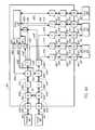
- FIG. 9Aillustrates yet another embodiment of a security tap 900 .
- many of the elements in FIG. 9Aare similar to the elements in FIG. 7 A.
- like elementsare referred to with like reference numerals, substituting 900 's for 700 's.
- a detailed description of security tap 900will not be provided, except where new reference numbers are introduced.
- FIG. 9Aillustrates a security tap which can operate in different modes. These modes are made possible by multiplexors 980 A through 980 G, which operation will be described in more detail below.
- Multiplexors 980 A through 980 Gare circuit devices that have several inputs and one user-selectable output.
- security tap 900is substantially the same with respect to firewall 906 , switch 908 , ports 904 A, 904 B, relays 926 A, 926 B, transformers 928 A, 928 B and physical layer devices 930 A, 930 B. However, at fan out buffers 932 A, 932 B, the configuration of security tap 900 differs from the embodiment of FIG. 7 A.
- Fan out buffers 932 A, 932 Bthe data packets are duplicated and sent out to a number of different locations.
- Fan out buffers 932 Asends information to switch 902 , multiplexor 980 F, switch 956 , multiplexor 980 D and multiplexor 980 B through communication lines 914 E through 914 I, respectively.
- fan out buffer 932 Bsend data packets to multiplexor 980 A, switch 902 , multiplexor 980 E, switch 956 and multiplexor 980 C through communication lines 916 E through 916 I, respectively.
- Switch 956combines the information from communication lines 914 G and 916 H. In addition, as will be discussed in more detail below, switch 956 mirrors or duplicates the combined information from communication lines 914 G and 916 H such that the mirrored information can be sent to both multiplexors 980 C and 980 E through communication lines 984 A and 984 B, respectively.
- Multiplexors 980 C through 980 Fsend information to physical layer devices 930 C through 930 F through communication lines 982 C through 982 F, respectively.
- Physical layer devices 930 C through 930 Ftransmit information to transformers 928 C through 928 F through communication lines 918 B, 920 B, 922 B, 924 B, respectively.
- transformers 928 C through 928 Ftransmit information to ports 904 C through 904 F via communication lines 918 A, 920 A, 922 A, 924 A, respectively.
- Physical layer devices 930 C and 930 Ftransmit information to multiplexor 980 G through communication lines 918 C, 924 C, respectively.
- Multiplexor 980 Gis connected to switch 902 through communication line 986 .
- Switch 902is connected to multiplexors 980 A, 980 B through communication lines 988 A, 988 B, respectively.
- multiplexors 980 A, 980 Bare connected to physical layer devices 930 A, 930 B through communication lines 982 A, 982 B, respectively.
- client device 950is connected to FPGA 960 in a similar manner as reflected in FIG. 8 A. That is, port 904 G can be configured as an Xport to allow serial communication between client device 950 and FPGA 960 .
- security tap 900includes port 904 H configured as a Mini Din Serial port. In another embodiment, port 904 H could be a DB-9 serial port.
- Client device 950is connected to port 904 H through communication line 990 .
- port 904 His connected to FPGA 960 through communication line 990 A.
- Port 904 Henables serial communication between client device 950 and FPGA 960 .
- client device 950can communicate with FPGA 960 to debug security tap 900 , configure the IP setup of security tap 900 , and other control functions.
- security tap 900The combination of switch 902 , switch 956 and multiplexors 980 A through 980 G allows security tap 900 to operate in different modes.
- switches 902 and 956 and multiplexor 980 Gare taken out of the main data link by FPGA 960 .
- FPGA 960controls the multiplexors so that the data coming and going to the switches is not used.
- FPGA 960controls multiplexors 980 A, 980 B to select communication lines 914 I and 916 E and ignore lines 988 A and 988 B. While ports 904 C and 904 F are configured for bi-directional data flow, the data entering the security tap 900 from testing equipment 910 and intrusion detection device 912 is not used.
- each port 904 C through 904 Fis required to properly connect testing equipment 910 and intrusion detection device 912 .
- intrusion detection device 912would require an additional communication line and external switch to communicate with firewall 906 .
- security tap 900can be operated in a completely passive manner.
- switch 902In a “switching” mode, testing equipment 910 and intrusion detection device 912 are still not allowed to transmit information. However, in this embodiment, switch 902 is enabled while switch 956 is disabled by FPGA 960 . At fan out buffers 932 A, 932 B, the communication lines that are used are communication lines 914 E, 914 F, 914 H, 916 F, 916 G, 916 I. Thus, an additional data path is created from switch 902 to multiplexors 980 A, 980 B through communication lines 988 A, 988 B. FPGA 960 controls multiplexors 980 A, 980 B to only acknowledge or accept information from communication lines 988 A, 988 B.
- Multiplexors 980 A, 980 Btransmit information to physical layer devices 930 A, 930 B through communication lines 982 A, 982 B.
- Ports 904 C through 904 Fstill operate in a uni-directional mode.
- the testing equipment 910 and intrusion detection device 912still operate in a passive manner.
- switch 902 and multiplexor 980 Gare used while switch 956 is not used.
- the return path formed by communication lines 918 C, 924 C between physical layer devices 930 C, 930 F and multiplexor 980 Gis enabled.
- Data flow through ports 904 C and 904 Fis now bi-directional such that data packets (i.e., kill packets) can be sent from intrusion detection system 912 from either port.
- testing equipment 910 and intrusion detection system 912are interchangeable. That is, intrusion detection system 912 may be connected to either ports 904 C, 904 D or ports 904 E, 904 F.
- testing equipment 910may be connected to either ports 904 C, 904 D or ports 904 E, 904 F. Thus, it is also contemplated that testing equipment 910 is able to transmit data packets into security tap 900 through either port 904 C or port 904 F.
- switches 902 and multiplexor 980 Gare enabled by FPGA 960 .
- testing equipment 910 and intrusion detection system 912are enable to send data packets into security tap 900 through ports 904 C or 904 E as described above.
- FPGA 960controls multiplexors 980 A, 980 B to only acknowledge transmissions from communication lines 988 A, 988 B.
- different port configurationsare possible depending on how FPGA 960 controls multiplexors 980 C and 980 E. These configurations are based on whether multiplexors 980 C and 980 E are enabled or disabled by FPGA 960 .
- FPGA 960allows ports 904 C through 904 E to have different configurations based on the desire of the user.
- the first port configurationis similar to the port configuration of FIG. 3 .
- Ports 904 C and 904 Eare configured to receive a representation of data transmissions from switch 908 through communication lines 916 I and 916 G, respectively.
- Ports 904 D and 904 Freceive a representation of data transmission from firewall 906 through communication lines 914 H and 914 F, respectively.
- switch 956would be disabled.
- FPGA 960would control multiplexors 980 C and 980 E to acknowledge only transmissions from communication lines 916 I and 916 G.
- Ports 904 C and 904 Eare configured to allow bi-directional flow of data to allow testing equipment 910 or intrusion detection system 912 to send data packets therethrough.
- ports 904 C and 904 Eare interchangeable to allow testing equipment 910 and intrusion detection system 912 to be interchangeable.
- the second port configurationis similar to the port configuration of FIG. 7 A.
- FPGA 960enables switch 956 .
- Switch 956combines the information from fan out buffers 932 A, 932 B.
- Switch 956duplicates the combined information and sends the information to multiplexors 980 C and 980 E through communication lines 984 A, 984 B.
- the second port configurationfocuses on ports 904 E and 904 F.
- FPGA 960controls multiplexor 980 E to acknowledge transmissions from switch 956 , but not communication line 916 G.
- FPGA 960controls multiplexor 980 F to not acknowledge transmissions from communication line 914 F. It will be appreciated that all of the necessary information contained in communication lines 916 G and 914 F is represented in communication line 984 B.
- port 904 Econtains only outgoing data flow
- port 904 Fcontains only ingoing data flow.
- such a port configurationmay be advantageous in some intrusion detection systems.
- the third port configurationis similar to the port configuration of FIG. 8 A.
- FPGA 960enables switch 956 , which sends a duplicate of information to multiplexor 980 C through communication line 984 A.
- the third port configurationfocuses on ports 904 C and 904 D.
- FPGA 960controls multiplexor 980 C to ignore the transmissions from communication line 916 I and use communication line 984 A to send out port 904 C.
- FPGA 960controls multiplexor 980 D to ignore the transmissions from communication line 914 H. It will be appreciated that all of the necessary information contained in communication lines 916 I and 914 H is represented in communication line 984 A.
- port 904 Cis configured to allow bi-directional data flow while port 904 D is essentially disabled.
- some embodiments of intrusion detections systemsare configured to be connected to a security tap through a single cable.
- port 904 Callows transmission of data packets from intrusion detection system 912 .
- FPGA 960can control switch 956 and multiplexors 980 C through 980 F so that different modes are enabled.
- the following tablegives an example of the types of modes that can be enabled simultaneously.
- the terms OFF/ONare used for switch 956 to indicate whether the FPGA 960 has disabled or enabled switch 956 .
- the term OFFis used with multiplexors 980 D and 980 F where no transmissions are allowed therethrough.
- the term ONis used with multiplexors 980 C through 980 F to indicate that the multiplexors simply allow whatever transmissions it is receiving to pass there through.
- MODE 1 and MODE 2are used with the multiplexors where there is a possibility of simultaneous transmissions from the fan out buffers and from switch 956 .
- MODE 1only acknowledges transmissions from the communication line coming from the fan out buffer.
- MODE 2only acknowledges transmission from switch 956 .
- each configuration of portsmay be interchangeably used for either testing equipment 910 or intrusion detection system 912 .
- testing equipment 910 and intrusion detection systems 912may be connected to security tap 900 at any one time, depending on the user's preferences.
- switches 902 and 956are enabled while multiplexor 980 G is disabled. This disables the return paths created by communication lines 918 C and 918 D.
- different port configurationsare still enabled depending on how the components of security tap 900 are operated by FPGA 960 .
- the first port configuration discussed aboveis possible, wherein multiplexors 980 C through 980 F acknowledge transmissions from communication lines 914 F, 916 G, 914 G and 916 I, respectively.
- a fourth port configurationis possible in either ports 904 C and 904 D or ports 904 E and 904 F.
- FPGA 960disables multiplexor 980 D.
- Port 904 Cdelivers a representation of the signal from the main communication cable as combined by switch 956 .
- FPGA 960controls multiplexor 980 C to acknowledge only transmissions from communication line 984 A. Because multiplexor 980 G is also disabled, the return path from physical layer device 930 C to multiplexor 980 G is disabled. Thus, only uni-directional transmission flow through port 904 C.
- multiplexor 980 Dis disabled so that no transmissions are allowed through port 904 D.
- testing equipment 910 or intrusion detection system 912may be connected to port 904 C through a single cable to operate in a passive manner.
- port 904 Edelivers a representation of the signal from the main communication cable as combined by switch 956 .
- FPGA 960disables multiplexor 980 F so that transmissions are not allowed through port 904 F.
- testing equipment 910 or intrusion detection system 912may be connected to port 904 E through a single cable to operate in a passive manner.
- the following tableprovides the types of port configurations that can be operated simultaneously in the “switching/combined tap” mode, with the same terminology from the previous table being applied here.
- network tap 900may operate in a number of different modes controlled by the operation of FPGA 960 . Within these modes are a number of port configurations which may be used to connect different types of testing equipment or intrusion detection systems. This may be advantageous where different manufacturers of testing equipment or intrusion detection systems may implement different connections such that security tap 900 may be used on virtually any network system.
- Switching between modesmay be facilitated by a software program located on client device 950 .
- a password or another type of appropriate management securityis required to operate the software to prevent unauthorized access to the network.
- softwaremay be loaded into FPGA 960 through client device 950 .
- a usermay be able to manually switch modes through switches or buttons on the front panel of security tap 900 .
- switch 902acts as a routing node in security tap 900 .
- FPGA 960allows the embodiment of FIG. 9A to have all of the functionality described with reference to FIG. 7 A. That is, FPGA 960 controls switches, physical layer devices, relays, and now multiplexors, as illustrated in FIG. 9B by control lines 966 A through 966 Q. FPGA 960 may obtain statistics from switches 902 , 956 . FPGA 960 is also programmable such that a user may program additional functionality through client device 950 . Furthermore, the general concepts of the configuration of the signal format illustrated in FIG. 7C also apply to this particular embodiment. In addition, the process logic of FPGA 960 is similar to the process logic of FPGA 760 described with reference to FIGS. 7D and 7E .
- the configuration of the routing nodedepends on many design considerations.
- the FPGAallows a user to customize the types of statistics to be extracted from the system, whereas a switch provides only limited statistics.
- the FPGAcan be programmed on-site or remotely, providing the user increased flexibility in its functional capabilities, whereas the switch is not programmable although it can be dynamically controlled.
- the FPGAtheoretically has a higher efficiency in preventing data collisions than the switch, whereas switches are known to drop some packets.
- the hardware for an FPGAis also less expensive than a switch.
- the FPGArequires extensive programming time, whereas switch technology is already developed in the art. Because the FPGA must be custom-designed, the development costs may be higher than those associated with the use of switches.
- the FPGA embodimentsalso may require extra physical layer devices to convert the signals to SGMII format, thus adding additional cost.
- a company called Xilinxlocated in San Jose, Calif., makes FPGA devices which have built-in SERDES that can receive differential signals up to 3.125 GHz. Using a Xilinx Virtex-II Pro FPGA, the extra physical layer devices would not be required.
- An additional benefit of using an FPGAis that the operation of the network tap can be digitally controlled in a robust and programmable way. This permits the network tap to perform any of a variety of operations that have not been possible in conventional network taps that do not include an FPGA or a similar digital controller. Some of these functions include the network analysis and statistics gathering operations described above.
Landscapes
- Engineering & Computer Science (AREA)
- Computer Security & Cryptography (AREA)
- Computer Hardware Design (AREA)
- Computing Systems (AREA)
- General Engineering & Computer Science (AREA)
- Computer Networks & Wireless Communication (AREA)
- Signal Processing (AREA)
- Data Exchanges In Wide-Area Networks (AREA)
- Small-Scale Networks (AREA)
Abstract
Description
| Ports | 904E/904F | Switch | MUX | MUX | |||
| configuration | configuration | ||||||
| 956 | 980E | MUX | 980F | ||||
| First | First | OFF | ON | ON | ON | ON | |
| First | Second | ON | MODE 1 | ON | MODE 2 | OFF | |
| Third | First | ON | MODE 2 | OFF | MODE 1 | ON | |
| Third | Second | ON | MODE 2 | OFF | MODE 2 | OFF | |
| Ports | 904E/904F | Switch | MUX | MUX | |||
| configuration | configuration | ||||||
| 956 | 980E | MUX | 980F | ||||
| First | First | OFF | ON | ON | ON | ON | |
| First | Fourth | ON | MODE 1 | ON | MODE 2 | OFF | |
| Fourth | First | ON | MODE 2 | OFF | MODE 1 | ON | |
| Fourth | Fourth | ON | MODE 2 | OFF | MODE 2 | OFF | |
Claims (30)
Priority Applications (2)
| Application Number | Priority Date | Filing Date | Title |
|---|---|---|---|
| US10/409,006US6898632B2 (en) | 2003-03-31 | 2003-04-07 | Network security tap for use with intrusion detection system |
| PCT/US2004/008499WO2004095305A1 (en) | 2003-03-31 | 2004-03-19 | Network security tap for use with intrusion detection system |
Applications Claiming Priority (2)
| Application Number | Priority Date | Filing Date | Title |
|---|---|---|---|
| US45916603P | 2003-03-31 | 2003-03-31 | |
| US10/409,006US6898632B2 (en) | 2003-03-31 | 2003-04-07 | Network security tap for use with intrusion detection system |
Publications (2)
| Publication Number | Publication Date |
|---|---|
| US20050005031A1 US20050005031A1 (en) | 2005-01-06 |
| US6898632B2true US6898632B2 (en) | 2005-05-24 |
Family
ID=33313083
Family Applications (1)
| Application Number | Title | Priority Date | Filing Date |
|---|---|---|---|
| US10/409,006Expired - LifetimeUS6898632B2 (en) | 2003-03-31 | 2003-04-07 | Network security tap for use with intrusion detection system |
Country Status (2)
| Country | Link |
|---|---|
| US (1) | US6898632B2 (en) |
| WO (1) | WO2004095305A1 (en) |
Cited By (212)
| Publication number | Priority date | Publication date | Assignee | Title |
|---|---|---|---|---|
| US20040001507A1 (en)* | 2002-05-14 | 2004-01-01 | Wilfried Krug | Data network interface and communication devices having a data network interface |
| US20040143761A1 (en)* | 2003-01-21 | 2004-07-22 | John Mendonca | Method for protecting security of network intrusion detection sensors |
| US20050050205A1 (en)* | 2003-08-29 | 2005-03-03 | Gordy Stephen C. | Multi-port network tap |
| US20050076227A1 (en)* | 2003-10-02 | 2005-04-07 | Koo-Hong Kang | In-line mode network intrusion detect and prevent system and method thereof |
| US20050114663A1 (en)* | 2003-11-21 | 2005-05-26 | Finisar Corporation | Secure network access devices with data encryption |
| US20050254490A1 (en)* | 2004-05-05 | 2005-11-17 | Tom Gallatin | Asymmetric packet switch and a method of use |
| US20060023709A1 (en)* | 2004-08-02 | 2006-02-02 | Hall Michael L | Inline intrusion detection using a single physical port |
| US20060059554A1 (en)* | 2004-09-13 | 2006-03-16 | Ofer Akerman | System and method for information technology intrusion prevention |
| US20060153092A1 (en)* | 2004-12-24 | 2006-07-13 | Eldad Matityahu | Active response communications network tap |
| US20060161983A1 (en)* | 2005-01-20 | 2006-07-20 | Cothrell Scott A | Inline intrusion detection |
| US20060256716A1 (en)* | 2005-05-13 | 2006-11-16 | Lockheed Martin Corporation | Electronic communication control |
| WO2006031486A3 (en)* | 2004-09-03 | 2006-12-07 | Univ California | A system for secure access to, and activation of, a network tap |
| US20070016767A1 (en)* | 2005-07-05 | 2007-01-18 | Netdevices, Inc. | Switching Devices Avoiding Degradation of Forwarding Throughput Performance When Downloading Signature Data Related to Security Applications |
| US20070162974A1 (en)* | 2005-07-09 | 2007-07-12 | Ads-Tec Automation Daten- Und Systemtechnik Gmbh | Protection System for a Data Processing Device |
| US20070210909A1 (en)* | 2006-03-09 | 2007-09-13 | Honeywell International Inc. | Intrusion detection in an IP connected security system |
| US20070253349A1 (en)* | 2005-11-15 | 2007-11-01 | Finisar Corporation | Passive Network Tap With Bidirectional Coupler and Associated Splitting Methods |
| US20080005782A1 (en)* | 2004-04-01 | 2008-01-03 | Ashar Aziz | Heuristic based capture with replay to virtual machine |
| US20080084876A1 (en)* | 2006-10-09 | 2008-04-10 | Robert Bosch Gmbh | System and method for intelligent data routing |
| US20080189410A1 (en)* | 2007-02-01 | 2008-08-07 | Finisar Corporation | Directing a network transaction to a probe |
| US7562389B1 (en) | 2004-07-30 | 2009-07-14 | Cisco Technology, Inc. | Method and system for network security |
| US20090245128A1 (en)* | 2007-08-07 | 2009-10-01 | Eldad Matityahu | Integrated switch tap arrangement with visual display arrangement and methods thereof |
| US20090303883A1 (en)* | 2008-06-05 | 2009-12-10 | David Kucharczyk | Ethernet switch-based network monitoring system and methods |
| WO2010083397A1 (en)* | 2009-01-15 | 2010-07-22 | Vss Monitoring, Inc. | Intelligent fast switch-over network tap system and methods |
| US20100192223A1 (en)* | 2004-04-01 | 2010-07-29 | Osman Abdoul Ismael | Detecting Malicious Network Content Using Virtual Environment Components |
| US7852554B2 (en) | 2005-04-20 | 2010-12-14 | The Regents Of The University Of California | Cryogenic immersion microscope |
| US20110078794A1 (en)* | 2009-09-30 | 2011-03-31 | Jayaraman Manni | Network-Based Binary File Extraction and Analysis for Malware Detection |
| US20110093951A1 (en)* | 2004-06-14 | 2011-04-21 | NetForts, Inc. | Computer worm defense system and method |
| US20110145912A1 (en)* | 2009-12-11 | 2011-06-16 | Moshe Litvin | Media access control address translation in virtualized environments |
| US20110164521A1 (en)* | 2007-08-07 | 2011-07-07 | Eldad Matityahu | Arrangement for utilization rate display and methods thereof |
| US20110211473A1 (en)* | 2010-02-28 | 2011-09-01 | Eldad Matityahu | Time machine device and methods thereof |
| US8204984B1 (en) | 2004-04-01 | 2012-06-19 | Fireeye, Inc. | Systems and methods for detecting encrypted bot command and control communication channels |
| US8375444B2 (en) | 2006-04-20 | 2013-02-12 | Fireeye, Inc. | Dynamic signature creation and enforcement |
| US8528086B1 (en) | 2004-04-01 | 2013-09-03 | Fireeye, Inc. | System and method of detecting computer worms |
| US8537690B2 (en) | 2007-12-27 | 2013-09-17 | Net Optics, Inc. | Director device arrangement with visual display arrangement and methods thereof |
| US8539582B1 (en) | 2004-04-01 | 2013-09-17 | Fireeye, Inc. | Malware containment and security analysis on connection |
| US8549638B2 (en) | 2004-06-14 | 2013-10-01 | Fireeye, Inc. | System and method of containing computer worms |
| US8561177B1 (en) | 2004-04-01 | 2013-10-15 | Fireeye, Inc. | Systems and methods for detecting communication channels of bots |
| US8566946B1 (en) | 2006-04-20 | 2013-10-22 | Fireeye, Inc. | Malware containment on connection |
| US8584239B2 (en) | 2004-04-01 | 2013-11-12 | Fireeye, Inc. | Virtual machine with dynamic data flow analysis |
| US8582472B2 (en) | 2007-08-07 | 2013-11-12 | Net Optics, Inc. | Arrangement for an enhanced communication network tap port aggregator and methods thereof |
| US8614946B1 (en) | 2013-06-07 | 2013-12-24 | Sideband Networks Inc. | Dynamic switch port monitoring |
| US20140022891A1 (en)* | 2010-02-28 | 2014-01-23 | Eldad Matityahu | Arrangements and methods for minimizing delay in high-speed taps |
| US8850571B2 (en) | 2008-11-03 | 2014-09-30 | Fireeye, Inc. | Systems and methods for detecting malicious network content |
| US8881282B1 (en) | 2004-04-01 | 2014-11-04 | Fireeye, Inc. | Systems and methods for malware attack detection and identification |
| US8898788B1 (en) | 2004-04-01 | 2014-11-25 | Fireeye, Inc. | Systems and methods for malware attack prevention |
| US8902735B2 (en) | 2010-02-28 | 2014-12-02 | Net Optics, Inc. | Gigabits zero-delay tap and methods thereof |
| US8990944B1 (en) | 2013-02-23 | 2015-03-24 | Fireeye, Inc. | Systems and methods for automatically detecting backdoors |
| US8997219B2 (en) | 2008-11-03 | 2015-03-31 | Fireeye, Inc. | Systems and methods for detecting malicious PDF network content |
| US9009823B1 (en) | 2013-02-23 | 2015-04-14 | Fireeye, Inc. | Framework for efficient security coverage of mobile software applications installed on mobile devices |
| US9009822B1 (en) | 2013-02-23 | 2015-04-14 | Fireeye, Inc. | Framework for multi-phase analysis of mobile applications |
| US9027135B1 (en) | 2004-04-01 | 2015-05-05 | Fireeye, Inc. | Prospective client identification using malware attack detection |
| WO2015074896A1 (en)* | 2013-11-19 | 2015-05-28 | Siemens Aktiengesellschaft | Method for acquiring data transmitted in a computer network comprising at least one computer, and data acquisition arrangement |
| US9104867B1 (en) | 2013-03-13 | 2015-08-11 | Fireeye, Inc. | Malicious content analysis using simulated user interaction without user involvement |
| US9106694B2 (en) | 2004-04-01 | 2015-08-11 | Fireeye, Inc. | Electronic message analysis for malware detection |
| US9159035B1 (en) | 2013-02-23 | 2015-10-13 | Fireeye, Inc. | Framework for computer application analysis of sensitive information tracking |
| US9171160B2 (en) | 2013-09-30 | 2015-10-27 | Fireeye, Inc. | Dynamically adaptive framework and method for classifying malware using intelligent static, emulation, and dynamic analyses |
| US9176843B1 (en) | 2013-02-23 | 2015-11-03 | Fireeye, Inc. | Framework for efficient security coverage of mobile software applications |
| US9189627B1 (en) | 2013-11-21 | 2015-11-17 | Fireeye, Inc. | System, apparatus and method for conducting on-the-fly decryption of encrypted objects for malware detection |
| US9195829B1 (en) | 2013-02-23 | 2015-11-24 | Fireeye, Inc. | User interface with real-time visual playback along with synchronous textual analysis log display and event/time index for anomalous behavior detection in applications |
| US9223972B1 (en) | 2014-03-31 | 2015-12-29 | Fireeye, Inc. | Dynamically remote tuning of a malware content detection system |
| US9241010B1 (en) | 2014-03-20 | 2016-01-19 | Fireeye, Inc. | System and method for network behavior detection |
| US9251343B1 (en) | 2013-03-15 | 2016-02-02 | Fireeye, Inc. | Detecting bootkits resident on compromised computers |
| US9262635B2 (en) | 2014-02-05 | 2016-02-16 | Fireeye, Inc. | Detection efficacy of virtual machine-based analysis with application specific events |
| US9294501B2 (en) | 2013-09-30 | 2016-03-22 | Fireeye, Inc. | Fuzzy hash of behavioral results |
| US9300686B2 (en) | 2013-06-28 | 2016-03-29 | Fireeye, Inc. | System and method for detecting malicious links in electronic messages |
| US9306974B1 (en) | 2013-12-26 | 2016-04-05 | Fireeye, Inc. | System, apparatus and method for automatically verifying exploits within suspect objects and highlighting the display information associated with the verified exploits |
| US9306959B2 (en) | 2010-02-26 | 2016-04-05 | Ixia | Dual bypass module and methods thereof |
| US9311479B1 (en) | 2013-03-14 | 2016-04-12 | Fireeye, Inc. | Correlation and consolidation of analytic data for holistic view of a malware attack |
| US9355247B1 (en) | 2013-03-13 | 2016-05-31 | Fireeye, Inc. | File extraction from memory dump for malicious content analysis |
| US9363280B1 (en) | 2014-08-22 | 2016-06-07 | Fireeye, Inc. | System and method of detecting delivery of malware using cross-customer data |
| US9367681B1 (en) | 2013-02-23 | 2016-06-14 | Fireeye, Inc. | Framework for efficient security coverage of mobile software applications using symbolic execution to reach regions of interest within an application |
| US9398028B1 (en) | 2014-06-26 | 2016-07-19 | Fireeye, Inc. | System, device and method for detecting a malicious attack based on communcations between remotely hosted virtual machines and malicious web servers |
| US9430646B1 (en) | 2013-03-14 | 2016-08-30 | Fireeye, Inc. | Distributed systems and methods for automatically detecting unknown bots and botnets |
| US9432389B1 (en) | 2014-03-31 | 2016-08-30 | Fireeye, Inc. | System, apparatus and method for detecting a malicious attack based on static analysis of a multi-flow object |
| US9438623B1 (en) | 2014-06-06 | 2016-09-06 | Fireeye, Inc. | Computer exploit detection using heap spray pattern matching |
| US9438613B1 (en) | 2015-03-30 | 2016-09-06 | Fireeye, Inc. | Dynamic content activation for automated analysis of embedded objects |
| US9483644B1 (en) | 2015-03-31 | 2016-11-01 | Fireeye, Inc. | Methods for detecting file altering malware in VM based analysis |
| US9495180B2 (en) | 2013-05-10 | 2016-11-15 | Fireeye, Inc. | Optimized resource allocation for virtual machines within a malware content detection system |
| US9519782B2 (en) | 2012-02-24 | 2016-12-13 | Fireeye, Inc. | Detecting malicious network content |
| US9536091B2 (en) | 2013-06-24 | 2017-01-03 | Fireeye, Inc. | System and method for detecting time-bomb malware |
| US20170026406A1 (en)* | 2013-12-20 | 2017-01-26 | Telefonaktiebolaget Lm Ericsson (Publ) | A Method for Providing a Connection Between a Communications Service Provider and an Internet Protocol, IP, Server, Providing a Service, as well as a Perimeter Network, Comprising the IP Server, and an IP Server Providing the Service |
| US9565202B1 (en) | 2013-03-13 | 2017-02-07 | Fireeye, Inc. | System and method for detecting exfiltration content |
| US9591015B1 (en) | 2014-03-28 | 2017-03-07 | Fireeye, Inc. | System and method for offloading packet processing and static analysis operations |
| US9594904B1 (en) | 2015-04-23 | 2017-03-14 | Fireeye, Inc. | Detecting malware based on reflection |
| US9594912B1 (en) | 2014-06-06 | 2017-03-14 | Fireeye, Inc. | Return-oriented programming detection |
| US9628507B2 (en) | 2013-09-30 | 2017-04-18 | Fireeye, Inc. | Advanced persistent threat (APT) detection center |
| US9628498B1 (en) | 2004-04-01 | 2017-04-18 | Fireeye, Inc. | System and method for bot detection |
| US9626509B1 (en) | 2013-03-13 | 2017-04-18 | Fireeye, Inc. | Malicious content analysis with multi-version application support within single operating environment |
| US9635039B1 (en) | 2013-05-13 | 2017-04-25 | Fireeye, Inc. | Classifying sets of malicious indicators for detecting command and control communications associated with malware |
| US9690933B1 (en) | 2014-12-22 | 2017-06-27 | Fireeye, Inc. | Framework for classifying an object as malicious with machine learning for deploying updated predictive models |
| US9690606B1 (en) | 2015-03-25 | 2017-06-27 | Fireeye, Inc. | Selective system call monitoring |
| US9690936B1 (en) | 2013-09-30 | 2017-06-27 | Fireeye, Inc. | Multistage system and method for analyzing obfuscated content for malware |
| US9736179B2 (en) | 2013-09-30 | 2017-08-15 | Fireeye, Inc. | System, apparatus and method for using malware analysis results to drive adaptive instrumentation of virtual machines to improve exploit detection |
| US9747446B1 (en) | 2013-12-26 | 2017-08-29 | Fireeye, Inc. | System and method for run-time object classification |
| US9773112B1 (en) | 2014-09-29 | 2017-09-26 | Fireeye, Inc. | Exploit detection of malware and malware families |
| US9813448B2 (en) | 2010-02-26 | 2017-11-07 | Ixia | Secured network arrangement and methods thereof |
| US9824216B1 (en) | 2015-12-31 | 2017-11-21 | Fireeye, Inc. | Susceptible environment detection system |
| US9825989B1 (en) | 2015-09-30 | 2017-11-21 | Fireeye, Inc. | Cyber attack early warning system |
| US9825976B1 (en) | 2015-09-30 | 2017-11-21 | Fireeye, Inc. | Detection and classification of exploit kits |
| US9824209B1 (en) | 2013-02-23 | 2017-11-21 | Fireeye, Inc. | Framework for efficient security coverage of mobile software applications that is usable to harden in the field code |
| US9838417B1 (en) | 2014-12-30 | 2017-12-05 | Fireeye, Inc. | Intelligent context aware user interaction for malware detection |
| US9888016B1 (en) | 2013-06-28 | 2018-02-06 | Fireeye, Inc. | System and method for detecting phishing using password prediction |
| US9921978B1 (en) | 2013-11-08 | 2018-03-20 | Fireeye, Inc. | System and method for enhanced security of storage devices |
| US9973531B1 (en) | 2014-06-06 | 2018-05-15 | Fireeye, Inc. | Shellcode detection |
| US10021124B2 (en) | 2003-07-01 | 2018-07-10 | Securityprofiling, Llc | Computer program product and apparatus for multi-path remediation |
| US10027689B1 (en) | 2014-09-29 | 2018-07-17 | Fireeye, Inc. | Interactive infection visualization for improved exploit detection and signature generation for malware and malware families |
| US10033747B1 (en) | 2015-09-29 | 2018-07-24 | Fireeye, Inc. | System and method for detecting interpreter-based exploit attacks |
| US10050998B1 (en) | 2015-12-30 | 2018-08-14 | Fireeye, Inc. | Malicious message analysis system |
| US10075455B2 (en) | 2014-12-26 | 2018-09-11 | Fireeye, Inc. | Zero-day rotating guest image profile |
| US10075466B1 (en) | 2003-07-01 | 2018-09-11 | Securityprofiling, Llc | Real-time vulnerability monitoring |
| US10084813B2 (en) | 2014-06-24 | 2018-09-25 | Fireeye, Inc. | Intrusion prevention and remedy system |
| US10089461B1 (en) | 2013-09-30 | 2018-10-02 | Fireeye, Inc. | Page replacement code injection |
| US10104110B2 (en) | 2003-07-01 | 2018-10-16 | Securityprofiling, Llc | Anti-vulnerability system, method, and computer program product |
| US10133863B2 (en) | 2013-06-24 | 2018-11-20 | Fireeye, Inc. | Zero-day discovery system |
| US10133866B1 (en) | 2015-12-30 | 2018-11-20 | Fireeye, Inc. | System and method for triggering analysis of an object for malware in response to modification of that object |
| US10148693B2 (en) | 2015-03-25 | 2018-12-04 | Fireeye, Inc. | Exploit detection system |
| US10169585B1 (en) | 2016-06-22 | 2019-01-01 | Fireeye, Inc. | System and methods for advanced malware detection through placement of transition events |
| US10176321B2 (en) | 2015-09-22 | 2019-01-08 | Fireeye, Inc. | Leveraging behavior-based rules for malware family classification |
| US10192052B1 (en) | 2013-09-30 | 2019-01-29 | Fireeye, Inc. | System, apparatus and method for classifying a file as malicious using static scanning |
| US10210329B1 (en) | 2015-09-30 | 2019-02-19 | Fireeye, Inc. | Method to detect application execution hijacking using memory protection |
| US10242185B1 (en) | 2014-03-21 | 2019-03-26 | Fireeye, Inc. | Dynamic guest image creation and rollback |
| US10284575B2 (en) | 2015-11-10 | 2019-05-07 | Fireeye, Inc. | Launcher for setting analysis environment variations for malware detection |
| US10341365B1 (en) | 2015-12-30 | 2019-07-02 | Fireeye, Inc. | Methods and system for hiding transition events for malware detection |
| US10417031B2 (en) | 2015-03-31 | 2019-09-17 | Fireeye, Inc. | Selective virtualization for security threat detection |
| US10447728B1 (en) | 2015-12-10 | 2019-10-15 | Fireeye, Inc. | Technique for protecting guest processes using a layered virtualization architecture |
| US10454950B1 (en) | 2015-06-30 | 2019-10-22 | Fireeye, Inc. | Centralized aggregation technique for detecting lateral movement of stealthy cyber-attacks |
| US10462173B1 (en) | 2016-06-30 | 2019-10-29 | Fireeye, Inc. | Malware detection verification and enhancement by coordinating endpoint and malware detection systems |
| US10476906B1 (en) | 2016-03-25 | 2019-11-12 | Fireeye, Inc. | System and method for managing formation and modification of a cluster within a malware detection system |
| US10474813B1 (en) | 2015-03-31 | 2019-11-12 | Fireeye, Inc. | Code injection technique for remediation at an endpoint of a network |
| US10491627B1 (en) | 2016-09-29 | 2019-11-26 | Fireeye, Inc. | Advanced malware detection using similarity analysis |
| US10503904B1 (en) | 2017-06-29 | 2019-12-10 | Fireeye, Inc. | Ransomware detection and mitigation |
| US10515214B1 (en) | 2013-09-30 | 2019-12-24 | Fireeye, Inc. | System and method for classifying malware within content created during analysis of a specimen |
| US10523609B1 (en) | 2016-12-27 | 2019-12-31 | Fireeye, Inc. | Multi-vector malware detection and analysis |
| US10528726B1 (en) | 2014-12-29 | 2020-01-07 | Fireeye, Inc. | Microvisor-based malware detection appliance architecture |
| US10554507B1 (en) | 2017-03-30 | 2020-02-04 | Fireeye, Inc. | Multi-level control for enhanced resource and object evaluation management of malware detection system |
| US10552610B1 (en) | 2016-12-22 | 2020-02-04 | Fireeye, Inc. | Adaptive virtual machine snapshot update framework for malware behavioral analysis |
| US10565378B1 (en) | 2015-12-30 | 2020-02-18 | Fireeye, Inc. | Exploit of privilege detection framework |
| US10572665B2 (en) | 2012-12-28 | 2020-02-25 | Fireeye, Inc. | System and method to create a number of breakpoints in a virtual machine via virtual machine trapping events |
| US10581879B1 (en) | 2016-12-22 | 2020-03-03 | Fireeye, Inc. | Enhanced malware detection for generated objects |
| US10581874B1 (en) | 2015-12-31 | 2020-03-03 | Fireeye, Inc. | Malware detection system with contextual analysis |
| US10587647B1 (en) | 2016-11-22 | 2020-03-10 | Fireeye, Inc. | Technique for malware detection capability comparison of network security devices |
| US10592678B1 (en) | 2016-09-09 | 2020-03-17 | Fireeye, Inc. | Secure communications between peers using a verified virtual trusted platform module |
| US10601863B1 (en) | 2016-03-25 | 2020-03-24 | Fireeye, Inc. | System and method for managing sensor enrollment |
| US10601865B1 (en) | 2015-09-30 | 2020-03-24 | Fireeye, Inc. | Detection of credential spearphishing attacks using email analysis |
| US10601848B1 (en) | 2017-06-29 | 2020-03-24 | Fireeye, Inc. | Cyber-security system and method for weak indicator detection and correlation to generate strong indicators |
| US10642753B1 (en) | 2015-06-30 | 2020-05-05 | Fireeye, Inc. | System and method for protecting a software component running in virtual machine using a virtualization layer |
| US10671721B1 (en) | 2016-03-25 | 2020-06-02 | Fireeye, Inc. | Timeout management services |
| US10671726B1 (en) | 2014-09-22 | 2020-06-02 | Fireeye Inc. | System and method for malware analysis using thread-level event monitoring |
| US10701091B1 (en) | 2013-03-15 | 2020-06-30 | Fireeye, Inc. | System and method for verifying a cyberthreat |
| US10706149B1 (en) | 2015-09-30 | 2020-07-07 | Fireeye, Inc. | Detecting delayed activation malware using a primary controller and plural time controllers |
| US10708163B1 (en) | 2018-07-13 | 2020-07-07 | Keysight Technologies, Inc. | Methods, systems, and computer readable media for automatic configuration and control of remote inline network monitoring probe |
| US10715542B1 (en) | 2015-08-14 | 2020-07-14 | Fireeye, Inc. | Mobile application risk analysis |
| US10713358B2 (en) | 2013-03-15 | 2020-07-14 | Fireeye, Inc. | System and method to extract and utilize disassembly features to classify software intent |
| US10728263B1 (en) | 2015-04-13 | 2020-07-28 | Fireeye, Inc. | Analytic-based security monitoring system and method |
| US10726127B1 (en) | 2015-06-30 | 2020-07-28 | Fireeye, Inc. | System and method for protecting a software component running in a virtual machine through virtual interrupts by the virtualization layer |
| US10740456B1 (en) | 2014-01-16 | 2020-08-11 | Fireeye, Inc. | Threat-aware architecture |
| US10747872B1 (en) | 2017-09-27 | 2020-08-18 | Fireeye, Inc. | System and method for preventing malware evasion |
| US10785255B1 (en) | 2016-03-25 | 2020-09-22 | Fireeye, Inc. | Cluster configuration within a scalable malware detection system |
| US10791132B1 (en)* | 2017-06-09 | 2020-09-29 | Amazon Technologies, Inc. | System and method for identifying suspicious network traffic |
| US10791138B1 (en) | 2017-03-30 | 2020-09-29 | Fireeye, Inc. | Subscription-based malware detection |
| US10798112B2 (en) | 2017-03-30 | 2020-10-06 | Fireeye, Inc. | Attribute-controlled malware detection |
| US10795991B1 (en) | 2016-11-08 | 2020-10-06 | Fireeye, Inc. | Enterprise search |
| US10805340B1 (en) | 2014-06-26 | 2020-10-13 | Fireeye, Inc. | Infection vector and malware tracking with an interactive user display |
| US10805346B2 (en) | 2017-10-01 | 2020-10-13 | Fireeye, Inc. | Phishing attack detection |
| US10817606B1 (en) | 2015-09-30 | 2020-10-27 | Fireeye, Inc. | Detecting delayed activation malware using a run-time monitoring agent and time-dilation logic |
| US10826931B1 (en) | 2018-03-29 | 2020-11-03 | Fireeye, Inc. | System and method for predicting and mitigating cybersecurity system misconfigurations |
| US10846117B1 (en) | 2015-12-10 | 2020-11-24 | Fireeye, Inc. | Technique for establishing secure communication between host and guest processes of a virtualization architecture |
| US10855700B1 (en) | 2017-06-29 | 2020-12-01 | Fireeye, Inc. | Post-intrusion detection of cyber-attacks during lateral movement within networks |
| US10893068B1 (en) | 2017-06-30 | 2021-01-12 | Fireeye, Inc. | Ransomware file modification prevention technique |
| US10893059B1 (en) | 2016-03-31 | 2021-01-12 | Fireeye, Inc. | Verification and enhancement using detection systems located at the network periphery and endpoint devices |
| US10904286B1 (en) | 2017-03-24 | 2021-01-26 | Fireeye, Inc. | Detection of phishing attacks using similarity analysis |
| US10902119B1 (en) | 2017-03-30 | 2021-01-26 | Fireeye, Inc. | Data extraction system for malware analysis |
| US10956477B1 (en) | 2018-03-30 | 2021-03-23 | Fireeye, Inc. | System and method for detecting malicious scripts through natural language processing modeling |
| US11003773B1 (en) | 2018-03-30 | 2021-05-11 | Fireeye, Inc. | System and method for automatically generating malware detection rule recommendations |
| US11005860B1 (en) | 2017-12-28 | 2021-05-11 | Fireeye, Inc. | Method and system for efficient cybersecurity analysis of endpoint events |
| US11075930B1 (en) | 2018-06-27 | 2021-07-27 | Fireeye, Inc. | System and method for detecting repetitive cybersecurity attacks constituting an email campaign |
| US11095610B2 (en)* | 2019-09-19 | 2021-08-17 | Blue Ridge Networks, Inc. | Methods and apparatus for autonomous network segmentation |
| US11108809B2 (en) | 2017-10-27 | 2021-08-31 | Fireeye, Inc. | System and method for analyzing binary code for malware classification using artificial neural network techniques |
| US11113086B1 (en) | 2015-06-30 | 2021-09-07 | Fireeye, Inc. | Virtual system and method for securing external network connectivity |
| US11176251B1 (en) | 2018-12-21 | 2021-11-16 | Fireeye, Inc. | Determining malware via symbolic function hash analysis |
| US11182473B1 (en) | 2018-09-13 | 2021-11-23 | Fireeye Security Holdings Us Llc | System and method for mitigating cyberattacks against processor operability by a guest process |
| US11200080B1 (en) | 2015-12-11 | 2021-12-14 | Fireeye Security Holdings Us Llc | Late load technique for deploying a virtualization layer underneath a running operating system |
| US11212257B2 (en) | 2018-06-22 | 2021-12-28 | Aeronix, Inc. | Multi-level secure ethernet switch |
| US11228491B1 (en) | 2018-06-28 | 2022-01-18 | Fireeye Security Holdings Us Llc | System and method for distributed cluster configuration monitoring and management |
| US11240275B1 (en) | 2017-12-28 | 2022-02-01 | Fireeye Security Holdings Us Llc | Platform and method for performing cybersecurity analyses employing an intelligence hub with a modular architecture |
| US11245703B2 (en) | 2019-09-27 | 2022-02-08 | Bank Of America Corporation | Security tool for considering multiple security contexts |
| US11244056B1 (en) | 2014-07-01 | 2022-02-08 | Fireeye Security Holdings Us Llc | Verification of trusted threat-aware visualization layer |
| US11258806B1 (en) | 2019-06-24 | 2022-02-22 | Mandiant, Inc. | System and method for automatically associating cybersecurity intelligence to cyberthreat actors |
| US11271955B2 (en) | 2017-12-28 | 2022-03-08 | Fireeye Security Holdings Us Llc | Platform and method for retroactive reclassification employing a cybersecurity-based global data store |
| US11310238B1 (en) | 2019-03-26 | 2022-04-19 | FireEye Security Holdings, Inc. | System and method for retrieval and analysis of operational data from customer, cloud-hosted virtual resources |
| US11316900B1 (en) | 2018-06-29 | 2022-04-26 | FireEye Security Holdings Inc. | System and method for automatically prioritizing rules for cyber-threat detection and mitigation |
| US11314859B1 (en) | 2018-06-27 | 2022-04-26 | FireEye Security Holdings, Inc. | Cyber-security system and method for detecting escalation of privileges within an access token |
| US11368475B1 (en) | 2018-12-21 | 2022-06-21 | Fireeye Security Holdings Us Llc | System and method for scanning remote services to locate stored objects with malware |
| US11392700B1 (en) | 2019-06-28 | 2022-07-19 | Fireeye Security Holdings Us Llc | System and method for supporting cross-platform data verification |
| US11436327B1 (en) | 2019-12-24 | 2022-09-06 | Fireeye Security Holdings Us Llc | System and method for circumventing evasive code for cyberthreat detection |
| US11522884B1 (en) | 2019-12-24 | 2022-12-06 | Fireeye Security Holdings Us Llc | Subscription and key management system |
| US11552986B1 (en) | 2015-12-31 | 2023-01-10 | Fireeye Security Holdings Us Llc | Cyber-security framework for application of virtual features |
| US11556640B1 (en) | 2019-06-27 | 2023-01-17 | Mandiant, Inc. | Systems and methods for automated cybersecurity analysis of extracted binary string sets |
| US11558401B1 (en) | 2018-03-30 | 2023-01-17 | Fireeye Security Holdings Us Llc | Multi-vector malware detection data sharing system for improved detection |
| US11601444B1 (en) | 2018-12-31 | 2023-03-07 | Fireeye Security Holdings Us Llc | Automated system for triage of customer issues |
| US11637862B1 (en) | 2019-09-30 | 2023-04-25 | Mandiant, Inc. | System and method for surfacing cyber-security threats with a self-learning recommendation engine |
| US11636198B1 (en) | 2019-03-30 | 2023-04-25 | Fireeye Security Holdings Us Llc | System and method for cybersecurity analyzer update and concurrent management system |
| US11677786B1 (en) | 2019-03-29 | 2023-06-13 | Fireeye Security Holdings Us Llc | System and method for detecting and protecting against cybersecurity attacks on servers |
| US11743290B2 (en) | 2018-12-21 | 2023-08-29 | Fireeye Security Holdings Us Llc | System and method for detecting cyberattacks impersonating legitimate sources |
| US11763004B1 (en) | 2018-09-27 | 2023-09-19 | Fireeye Security Holdings Us Llc | System and method for bootkit detection |
| US11838300B1 (en) | 2019-12-24 | 2023-12-05 | Musarubra Us Llc | Run-time configurable cybersecurity system |
| US11886585B1 (en) | 2019-09-27 | 2024-01-30 | Musarubra Us Llc | System and method for identifying and mitigating cyberattacks through malicious position-independent code execution |
| US11943248B1 (en) | 2018-04-06 | 2024-03-26 | Keysight Technologies, Inc. | Methods, systems, and computer readable media for network security testing using at least one emulated server |
| US11979428B1 (en) | 2016-03-31 | 2024-05-07 | Musarubra Us Llc | Technique for verifying exploit/malware at malware detection appliance through correlation with endpoints |
| US12074887B1 (en) | 2018-12-21 | 2024-08-27 | Musarubra Us Llc | System and method for selectively processing content after identification and removal of malicious content |
| US12200013B2 (en) | 2019-08-07 | 2025-01-14 | Musarubra Us Llc | System and method for detecting cyberattacks impersonating legitimate sources |
| US12445481B1 (en) | 2023-04-17 | 2025-10-14 | Musarubra Us Llc | Distributed malware detection system and submission workflow thereof |
Families Citing this family (41)
| Publication number | Priority date | Publication date | Assignee | Title |
|---|---|---|---|---|
| US7904454B2 (en)* | 2001-07-16 | 2011-03-08 | International Business Machines Corporation | Database access security |
| WO2005015370A1 (en)* | 2003-08-11 | 2005-02-17 | Telecom Italia S.P.A. | Method and system for detecting unauthorised use of a communication network |
| US8356349B2 (en)* | 2003-10-30 | 2013-01-15 | Telecom Italia S.P.A. | Method and system for intrusion prevention and deflection |
| US7409715B2 (en)* | 2003-12-10 | 2008-08-05 | Alcatel Lucent | Mechanism for detection of attacks based on impersonation in a wireless network |
| US7426512B1 (en)* | 2004-02-17 | 2008-09-16 | Guardium, Inc. | System and methods for tracking local database access |
| US8369218B2 (en)* | 2004-04-28 | 2013-02-05 | Net Optics, Inc. | Zero-interrupt network tap |
| US7422152B2 (en) | 2004-05-13 | 2008-09-09 | Cisco Technology, Inc. | Methods and devices for providing scalable RFID networks |
| US7607166B2 (en)* | 2004-07-12 | 2009-10-20 | Cisco Technology, Inc. | Secure manufacturing devices in a switched Ethernet network |
| US8458467B2 (en)* | 2005-06-21 | 2013-06-04 | Cisco Technology, Inc. | Method and apparatus for adaptive application message payload content transformation in a network infrastructure element |
| US7664879B2 (en)* | 2004-11-23 | 2010-02-16 | Cisco Technology, Inc. | Caching content and state data at a network element |
| US7987272B2 (en) | 2004-12-06 | 2011-07-26 | Cisco Technology, Inc. | Performing message payload processing functions in a network element on behalf of an application |
| US7725934B2 (en)* | 2004-12-07 | 2010-05-25 | Cisco Technology, Inc. | Network and application attack protection based on application layer message inspection |
| US8082304B2 (en)* | 2004-12-10 | 2011-12-20 | Cisco Technology, Inc. | Guaranteed delivery of application layer messages by a network element |
| US7606267B2 (en)* | 2004-12-10 | 2009-10-20 | Cisco Technology, Inc. | Reducing the sizes of application layer messages in a network element |
| US7698416B2 (en)* | 2005-01-25 | 2010-04-13 | Cisco Technology, Inc. | Application layer message-based server failover management by a network element |
| US7760859B2 (en)* | 2005-03-07 | 2010-07-20 | Net Optics, Inc. | Intelligent communications network tap port aggregator |
| US7926033B2 (en)* | 2005-05-27 | 2011-04-12 | Cisco Technology, Inc. | Method for supporting new network element software versions in an element management system without upgrading |
| US8266327B2 (en)* | 2005-06-21 | 2012-09-11 | Cisco Technology, Inc. | Identity brokering in a network element |
| CA2611340A1 (en)* | 2005-06-22 | 2007-01-04 | The Johns Hopkins University | Biomarker for ovarian cancer: ctap3-related proteins |
| US7345585B2 (en)* | 2005-08-01 | 2008-03-18 | Cisco Technology, Inc. | Network based device for providing RFID middleware functionality |
| US7970788B2 (en)* | 2005-08-02 | 2011-06-28 | International Business Machines Corporation | Selective local database access restriction |
| US7814548B2 (en) | 2005-09-13 | 2010-10-12 | Honeywell International Inc. | Instance based learning framework for effective behavior profiling and anomaly intrusion detection |
| US7933923B2 (en) | 2005-11-04 | 2011-04-26 | International Business Machines Corporation | Tracking and reconciling database commands |
| US8170020B2 (en)* | 2005-12-08 | 2012-05-01 | Microsoft Corporation | Leveraging active firewalls for network intrusion detection and retardation of attack |
| US7797406B2 (en)* | 2006-07-27 | 2010-09-14 | Cisco Technology, Inc. | Applying quality of service to application messages in network elements based on roles and status |
| US8141100B2 (en) | 2006-12-20 | 2012-03-20 | International Business Machines Corporation | Identifying attribute propagation for multi-tier processing |
| US8495367B2 (en) | 2007-02-22 | 2013-07-23 | International Business Machines Corporation | Nondestructive interception of secure data in transit |
| US8438425B1 (en)* | 2007-12-26 | 2013-05-07 | Emc (Benelux) B.V., S.A.R.L. | Testing a device for use in a storage area network |
| US7817636B2 (en)* | 2008-01-30 | 2010-10-19 | Cisco Technology, Inc. | Obtaining information on forwarding decisions for a packet flow |
| US8261326B2 (en) | 2008-04-25 | 2012-09-04 | International Business Machines Corporation | Network intrusion blocking security overlay |
| US20110087771A1 (en)* | 2009-10-05 | 2011-04-14 | Vss Monitoring, Inc. | Method, apparatus and system for a layer of stacked network captured traffic distribution devices |
| US8737197B2 (en) | 2010-02-26 | 2014-05-27 | Net Optic, Inc. | Sequential heartbeat packet arrangement and methods thereof |
| US20120023340A1 (en)* | 2010-07-23 | 2012-01-26 | Gigamon, Llc. | Network switch with power over ethernet |
| US9009782B2 (en)* | 2013-08-19 | 2015-04-14 | Freescale Semiconductor, Inc. | Steering traffic among multiple network services using a centralized dispatcher |
| US10009263B1 (en) | 2015-10-09 | 2018-06-26 | Gigamon Inc. | Network switch device for routing network traffic through an inline tool |
| US9912575B2 (en)* | 2015-11-18 | 2018-03-06 | Gigamon Inc. | Routing network traffic packets through a shared inline tool |
| DE102016205983A1 (en)* | 2016-04-11 | 2017-10-12 | Siemens Aktiengesellschaft | Arrangement for checking at least one firewall device and method for protecting at least one data receiver |
| US9781603B1 (en)* | 2016-10-20 | 2017-10-03 | Fortress Cyber Security, LLC | Combined network and physical security appliance |
| US11297071B2 (en)* | 2020-05-12 | 2022-04-05 | Siemens Mobility GmbH | Time-stamping for industrial unidirectional communication device with data integrity management |
| LU500592B1 (en)* | 2021-08-30 | 2023-02-28 | Phoenix Contact Gmbh & Co | Network coupling device for a network and network with a network coupling device |
| US20240039224A1 (en)* | 2022-07-29 | 2024-02-01 | Methode Electronics, Inc. | Single-pair ethernet pluggable module |
Citations (4)
| Publication number | Priority date | Publication date | Assignee | Title |
|---|---|---|---|---|
| US5940376A (en) | 1997-01-29 | 1999-08-17 | Cabletron Systems, Inc. | Method and apparatus to establish a tap-point in a switched network using self-configuring switches having distributed configuration capabilities |
| US5956337A (en)* | 1993-08-30 | 1999-09-21 | Washington University | ATM switch interface |
| US6026442A (en) | 1997-11-24 | 2000-02-15 | Cabletron Systems, Inc. | Method and apparatus for surveillance in communications networks |
| US6441931B1 (en)* | 1996-02-23 | 2002-08-27 | Nortel Networks Limited | Method and apparatus for monitoring a dedicated communications medium in a switched data network |
- 2003
- 2003-04-07USUS10/409,006patent/US6898632B2/ennot_activeExpired - Lifetime
- 2004
- 2004-03-19WOPCT/US2004/008499patent/WO2004095305A1/enactiveApplication Filing
Patent Citations (4)
| Publication number | Priority date | Publication date | Assignee | Title |
|---|---|---|---|---|
| US5956337A (en)* | 1993-08-30 | 1999-09-21 | Washington University | ATM switch interface |
| US6441931B1 (en)* | 1996-02-23 | 2002-08-27 | Nortel Networks Limited | Method and apparatus for monitoring a dedicated communications medium in a switched data network |
| US5940376A (en) | 1997-01-29 | 1999-08-17 | Cabletron Systems, Inc. | Method and apparatus to establish a tap-point in a switched network using self-configuring switches having distributed configuration capabilities |
| US6026442A (en) | 1997-11-24 | 2000-02-15 | Cabletron Systems, Inc. | Method and apparatus for surveillance in communications networks |
Cited By (386)
| Publication number | Priority date | Publication date | Assignee | Title |
|---|---|---|---|---|
| US20040001507A1 (en)* | 2002-05-14 | 2004-01-01 | Wilfried Krug | Data network interface and communication devices having a data network interface |
| US7808973B2 (en)* | 2002-05-14 | 2010-10-05 | Siemens Aktiengesellschaft | Data network interface and communication devices having a data network interface |
| US20040143761A1 (en)* | 2003-01-21 | 2004-07-22 | John Mendonca | Method for protecting security of network intrusion detection sensors |
| US7523503B2 (en)* | 2003-01-21 | 2009-04-21 | Hewlett-Packard Development Company, L.P. | Method for protecting security of network intrusion detection sensors |
| US10075466B1 (en) | 2003-07-01 | 2018-09-11 | Securityprofiling, Llc | Real-time vulnerability monitoring |
| US10154055B2 (en) | 2003-07-01 | 2018-12-11 | Securityprofiling, Llc | Real-time vulnerability monitoring |
| US11632388B1 (en) | 2003-07-01 | 2023-04-18 | Securityprofiling, Llc | Real-time vulnerability monitoring |
| US11310262B1 (en) | 2003-07-01 | 2022-04-19 | Security Profiling, LLC | Real-time vulnerability monitoring |
| US10547631B1 (en) | 2003-07-01 | 2020-01-28 | Securityprofiling, Llc | Real-time vulnerability monitoring |
| US10021124B2 (en) | 2003-07-01 | 2018-07-10 | Securityprofiling, Llc | Computer program product and apparatus for multi-path remediation |
| US10893066B1 (en) | 2003-07-01 | 2021-01-12 | Securityprofiling, Llc | Computer program product and apparatus for multi-path remediation |
| US10050988B2 (en) | 2003-07-01 | 2018-08-14 | Securityprofiling, Llc | Computer program product and apparatus for multi-path remediation |
| US10104110B2 (en) | 2003-07-01 | 2018-10-16 | Securityprofiling, Llc | Anti-vulnerability system, method, and computer program product |
| US7308705B2 (en)* | 2003-08-29 | 2007-12-11 | Finisar Corporation | Multi-port network tap |
| US20050050205A1 (en)* | 2003-08-29 | 2005-03-03 | Gordy Stephen C. | Multi-port network tap |
| US7401145B2 (en)* | 2003-10-02 | 2008-07-15 | Electronics And Telecommunications Research Institute | In-line mode network intrusion detect and prevent system and method thereof |
| US20050076227A1 (en)* | 2003-10-02 | 2005-04-07 | Koo-Hong Kang | In-line mode network intrusion detect and prevent system and method thereof |
| US20050114663A1 (en)* | 2003-11-21 | 2005-05-26 | Finisar Corporation | Secure network access devices with data encryption |
| US10068091B1 (en) | 2004-04-01 | 2018-09-04 | Fireeye, Inc. | System and method for malware containment |
| US9356944B1 (en) | 2004-04-01 | 2016-05-31 | Fireeye, Inc. | System and method for detecting malicious traffic using a virtual machine configured with a select software environment |
| US10284574B1 (en) | 2004-04-01 | 2019-05-07 | Fireeye, Inc. | System and method for threat detection and identification |
| US20080005782A1 (en)* | 2004-04-01 | 2008-01-03 | Ashar Aziz | Heuristic based capture with replay to virtual machine |
| US10165000B1 (en) | 2004-04-01 | 2018-12-25 | Fireeye, Inc. | Systems and methods for malware attack prevention by intercepting flows of information |
| US10567405B1 (en) | 2004-04-01 | 2020-02-18 | Fireeye, Inc. | System for detecting a presence of malware from behavioral analysis |
| US10587636B1 (en) | 2004-04-01 | 2020-03-10 | Fireeye, Inc. | System and method for bot detection |
| US10097573B1 (en) | 2004-04-01 | 2018-10-09 | Fireeye, Inc. | Systems and methods for malware defense |
| US10623434B1 (en) | 2004-04-01 | 2020-04-14 | Fireeye, Inc. | System and method for virtual analysis of network data |
| US8635696B1 (en) | 2004-04-01 | 2014-01-21 | Fireeye, Inc. | System and method of detecting time-delayed malicious traffic |
| US10757120B1 (en) | 2004-04-01 | 2020-08-25 | Fireeye, Inc. | Malicious network content detection |
| US20100192223A1 (en)* | 2004-04-01 | 2010-07-29 | Osman Abdoul Ismael | Detecting Malicious Network Content Using Virtual Environment Components |
| US10027690B2 (en) | 2004-04-01 | 2018-07-17 | Fireeye, Inc. | Electronic message analysis for malware detection |
| US11082435B1 (en) | 2004-04-01 | 2021-08-03 | Fireeye, Inc. | System and method for threat detection and identification |
| US11153341B1 (en) | 2004-04-01 | 2021-10-19 | Fireeye, Inc. | System and method for detecting malicious network content using virtual environment components |
| US9912684B1 (en) | 2004-04-01 | 2018-03-06 | Fireeye, Inc. | System and method for virtual analysis of network data |
| US9838411B1 (en) | 2004-04-01 | 2017-12-05 | Fireeye, Inc. | Subscriber based protection system |
| US9661018B1 (en) | 2004-04-01 | 2017-05-23 | Fireeye, Inc. | System and method for detecting anomalous behaviors using a virtual machine environment |
| US9628498B1 (en) | 2004-04-01 | 2017-04-18 | Fireeye, Inc. | System and method for bot detection |
| US9591020B1 (en) | 2004-04-01 | 2017-03-07 | Fireeye, Inc. | System and method for signature generation |
| US9516057B2 (en) | 2004-04-01 | 2016-12-06 | Fireeye, Inc. | Systems and methods for computer worm defense |
| US10511614B1 (en) | 2004-04-01 | 2019-12-17 | Fireeye, Inc. | Subscription based malware detection under management system control |
| US9306960B1 (en) | 2004-04-01 | 2016-04-05 | Fireeye, Inc. | Systems and methods for unauthorized activity defense |
| US9282109B1 (en) | 2004-04-01 | 2016-03-08 | Fireeye, Inc. | System and method for analyzing packets |
| US11637857B1 (en) | 2004-04-01 | 2023-04-25 | Fireeye Security Holdings Us Llc | System and method for detecting malicious traffic using a virtual machine configured with a select software environment |
| US9197664B1 (en) | 2004-04-01 | 2015-11-24 | Fire Eye, Inc. | System and method for malware containment |
| US9106694B2 (en) | 2004-04-01 | 2015-08-11 | Fireeye, Inc. | Electronic message analysis for malware detection |
| US8171553B2 (en)* | 2004-04-01 | 2012-05-01 | Fireeye, Inc. | Heuristic based capture with replay to virtual machine |
| US8204984B1 (en) | 2004-04-01 | 2012-06-19 | Fireeye, Inc. | Systems and methods for detecting encrypted bot command and control communication channels |
| US8291499B2 (en) | 2004-04-01 | 2012-10-16 | Fireeye, Inc. | Policy based capture with replay to virtual machine |
| US9071638B1 (en) | 2004-04-01 | 2015-06-30 | Fireeye, Inc. | System and method for malware containment |
| US9027135B1 (en) | 2004-04-01 | 2015-05-05 | Fireeye, Inc. | Prospective client identification using malware attack detection |
| US8984638B1 (en) | 2004-04-01 | 2015-03-17 | Fireeye, Inc. | System and method for analyzing suspicious network data |
| US8898788B1 (en) | 2004-04-01 | 2014-11-25 | Fireeye, Inc. | Systems and methods for malware attack prevention |
| US8528086B1 (en) | 2004-04-01 | 2013-09-03 | Fireeye, Inc. | System and method of detecting computer worms |
| US8881282B1 (en) | 2004-04-01 | 2014-11-04 | Fireeye, Inc. | Systems and methods for malware attack detection and identification |
| US8539582B1 (en) | 2004-04-01 | 2013-09-17 | Fireeye, Inc. | Malware containment and security analysis on connection |
| US8793787B2 (en) | 2004-04-01 | 2014-07-29 | Fireeye, Inc. | Detecting malicious network content using virtual environment components |
| US8561177B1 (en) | 2004-04-01 | 2013-10-15 | Fireeye, Inc. | Systems and methods for detecting communication channels of bots |
| US8776229B1 (en) | 2004-04-01 | 2014-07-08 | Fireeye, Inc. | System and method of detecting malicious traffic while reducing false positives |
| US8584239B2 (en) | 2004-04-01 | 2013-11-12 | Fireeye, Inc. | Virtual machine with dynamic data flow analysis |
| US9231889B2 (en) | 2004-05-05 | 2016-01-05 | Gigamon Inc. | Packet switch and method of use |
| US20110044349A1 (en)* | 2004-05-05 | 2011-02-24 | Gigamon Llc. | Packet switch and method of use |
| US20050254490A1 (en)* | 2004-05-05 | 2005-11-17 | Tom Gallatin | Asymmetric packet switch and a method of use |
| US9225669B2 (en) | 2004-05-05 | 2015-12-29 | Gigamon Inc. | Packet switch and method of use |
| US9391925B2 (en) | 2004-05-05 | 2016-07-12 | Gigamon Inc. | Packet switch methods and systems |
| US9077656B2 (en) | 2004-05-05 | 2015-07-07 | Gigamon Inc. | Packet switch methods and systems |
| US8391286B2 (en) | 2004-05-05 | 2013-03-05 | Gigamon Llc | Packet switch methods |
| US7835358B2 (en)* | 2004-05-05 | 2010-11-16 | Gigamon Llc. | Packet switch and method of use |
| US20110093951A1 (en)* | 2004-06-14 | 2011-04-21 | NetForts, Inc. | Computer worm defense system and method |
| US9838416B1 (en) | 2004-06-14 | 2017-12-05 | Fireeye, Inc. | System and method of detecting malicious content |
| US8549638B2 (en) | 2004-06-14 | 2013-10-01 | Fireeye, Inc. | System and method of containing computer worms |
| US8006305B2 (en) | 2004-06-14 | 2011-08-23 | Fireeye, Inc. | Computer worm defense system and method |
| US7562389B1 (en) | 2004-07-30 | 2009-07-14 | Cisco Technology, Inc. | Method and system for network security |
| US20060023709A1 (en)* | 2004-08-02 | 2006-02-02 | Hall Michael L | Inline intrusion detection using a single physical port |
| US7555774B2 (en) | 2004-08-02 | 2009-06-30 | Cisco Technology, Inc. | Inline intrusion detection using a single physical port |
| WO2006031486A3 (en)* | 2004-09-03 | 2006-12-07 | Univ California | A system for secure access to, and activation of, a network tap |
| US20060059554A1 (en)* | 2004-09-13 | 2006-03-16 | Ofer Akerman | System and method for information technology intrusion prevention |
| US20060153092A1 (en)* | 2004-12-24 | 2006-07-13 | Eldad Matityahu | Active response communications network tap |
| US8320242B2 (en) | 2004-12-24 | 2012-11-27 | Net Optics, Inc. | Active response communications network tap |
| US9009830B2 (en)* | 2005-01-20 | 2015-04-14 | Cisco Technology, Inc. | Inline intrusion detection |
| US20060161983A1 (en)* | 2005-01-20 | 2006-07-20 | Cothrell Scott A | Inline intrusion detection |
| US20100226383A1 (en)* | 2005-01-20 | 2010-09-09 | Cisco Technology, Inc. | Inline Intrusion Detection |
| US7725938B2 (en)* | 2005-01-20 | 2010-05-25 | Cisco Technology, Inc. | Inline intrusion detection |
| US7852554B2 (en) | 2005-04-20 | 2010-12-14 | The Regents Of The University Of California | Cryogenic immersion microscope |
| US7599289B2 (en)* | 2005-05-13 | 2009-10-06 | Lockheed Martin Corporation | Electronic communication control |
| US20060256716A1 (en)* | 2005-05-13 | 2006-11-16 | Lockheed Martin Corporation | Electronic communication control |
| US20070016767A1 (en)* | 2005-07-05 | 2007-01-18 | Netdevices, Inc. | Switching Devices Avoiding Degradation of Forwarding Throughput Performance When Downloading Signature Data Related to Security Applications |
| US20070162974A1 (en)* | 2005-07-09 | 2007-07-12 | Ads-Tec Automation Daten- Und Systemtechnik Gmbh | Protection System for a Data Processing Device |
| US20070253349A1 (en)* | 2005-11-15 | 2007-11-01 | Finisar Corporation | Passive Network Tap With Bidirectional Coupler and Associated Splitting Methods |
| US7860033B2 (en)* | 2005-11-15 | 2010-12-28 | Light Greta L | Passive network tap with bidirectional coupler and associated splitting methods |
| US20070210909A1 (en)* | 2006-03-09 | 2007-09-13 | Honeywell International Inc. | Intrusion detection in an IP connected security system |
| US8566946B1 (en) | 2006-04-20 | 2013-10-22 | Fireeye, Inc. | Malware containment on connection |
| US8375444B2 (en) | 2006-04-20 | 2013-02-12 | Fireeye, Inc. | Dynamic signature creation and enforcement |
| US7912981B2 (en) | 2006-10-09 | 2011-03-22 | Robert Bosch Gmbh | System and method for intelligent data routing |
| US20080084876A1 (en)* | 2006-10-09 | 2008-04-10 | Robert Bosch Gmbh | System and method for intelligent data routing |
| US20080189410A1 (en)* | 2007-02-01 | 2008-08-07 | Finisar Corporation | Directing a network transaction to a probe |
| US20090245128A1 (en)* | 2007-08-07 | 2009-10-01 | Eldad Matityahu | Integrated switch tap arrangement with visual display arrangement and methods thereof |
| US9712419B2 (en) | 2007-08-07 | 2017-07-18 | Ixia | Integrated switch tap arrangement and methods thereof |
| US8094576B2 (en)* | 2007-08-07 | 2012-01-10 | Net Optic, Inc. | Integrated switch tap arrangement with visual display arrangement and methods thereof |
| US20110164521A1 (en)* | 2007-08-07 | 2011-07-07 | Eldad Matityahu | Arrangement for utilization rate display and methods thereof |
| US8582472B2 (en) | 2007-08-07 | 2013-11-12 | Net Optics, Inc. | Arrangement for an enhanced communication network tap port aggregator and methods thereof |
| US8432827B2 (en) | 2007-08-07 | 2013-04-30 | Net Optics, Inc. | Arrangement for utilization rate display and methods thereof |
| US8537690B2 (en) | 2007-12-27 | 2013-09-17 | Net Optics, Inc. | Director device arrangement with visual display arrangement and methods thereof |
| US20090303883A1 (en)* | 2008-06-05 | 2009-12-10 | David Kucharczyk | Ethernet switch-based network monitoring system and methods |
| US7792046B2 (en) | 2008-06-05 | 2010-09-07 | Vss Monitoring, Inc. | Ethernet switch-based network monitoring system and methods |
| US8990939B2 (en) | 2008-11-03 | 2015-03-24 | Fireeye, Inc. | Systems and methods for scheduling analysis of network content for malware |
| US9438622B1 (en) | 2008-11-03 | 2016-09-06 | Fireeye, Inc. | Systems and methods for analyzing malicious PDF network content |
| US9118715B2 (en) | 2008-11-03 | 2015-08-25 | Fireeye, Inc. | Systems and methods for detecting malicious PDF network content |
| US9954890B1 (en) | 2008-11-03 | 2018-04-24 | Fireeye, Inc. | Systems and methods for analyzing PDF documents |
| US8997219B2 (en) | 2008-11-03 | 2015-03-31 | Fireeye, Inc. | Systems and methods for detecting malicious PDF network content |
| US8850571B2 (en) | 2008-11-03 | 2014-09-30 | Fireeye, Inc. | Systems and methods for detecting malicious network content |
| WO2010083397A1 (en)* | 2009-01-15 | 2010-07-22 | Vss Monitoring, Inc. | Intelligent fast switch-over network tap system and methods |
| US11381578B1 (en) | 2009-09-30 | 2022-07-05 | Fireeye Security Holdings Us Llc | Network-based binary file extraction and analysis for malware detection |
| US20110078794A1 (en)* | 2009-09-30 | 2011-03-31 | Jayaraman Manni | Network-Based Binary File Extraction and Analysis for Malware Detection |
| US8832829B2 (en) | 2009-09-30 | 2014-09-09 | Fireeye, Inc. | Network-based binary file extraction and analysis for malware detection |
| US8935779B2 (en) | 2009-09-30 | 2015-01-13 | Fireeye, Inc. | Network-based binary file extraction and analysis for malware detection |
| US8640221B2 (en)* | 2009-12-11 | 2014-01-28 | Juniper Networks, Inc. | Media access control address translation in virtualized environments |
| US9413719B2 (en) | 2009-12-11 | 2016-08-09 | Juniper Networks, Inc. | Media access control address translation in virtualized environments |
| US20110145912A1 (en)* | 2009-12-11 | 2011-06-16 | Moshe Litvin | Media access control address translation in virtualized environments |
| US9894037B2 (en) | 2009-12-11 | 2018-02-13 | Juniper Networks, Inc. | Media access control address translation in virtualized environments |
| US9258325B2 (en) | 2009-12-11 | 2016-02-09 | Juniper Networks, Inc. | Media access control address translation in virtualized environments |
| US9813448B2 (en) | 2010-02-26 | 2017-11-07 | Ixia | Secured network arrangement and methods thereof |
| US9306959B2 (en) | 2010-02-26 | 2016-04-05 | Ixia | Dual bypass module and methods thereof |
| US8902735B2 (en) | 2010-02-28 | 2014-12-02 | Net Optics, Inc. | Gigabits zero-delay tap and methods thereof |
| US20140022891A1 (en)* | 2010-02-28 | 2014-01-23 | Eldad Matityahu | Arrangements and methods for minimizing delay in high-speed taps |
| US8755293B2 (en) | 2010-02-28 | 2014-06-17 | Net Optics, Inc. | Time machine device and methods thereof |
| US9749261B2 (en)* | 2010-02-28 | 2017-08-29 | Ixia | Arrangements and methods for minimizing delay in high-speed taps |
| US20110211473A1 (en)* | 2010-02-28 | 2011-09-01 | Eldad Matityahu | Time machine device and methods thereof |
| US9519782B2 (en) | 2012-02-24 | 2016-12-13 | Fireeye, Inc. | Detecting malicious network content |
| US10282548B1 (en) | 2012-02-24 | 2019-05-07 | Fireeye, Inc. | Method for detecting malware within network content |
| US10572665B2 (en) | 2012-12-28 | 2020-02-25 | Fireeye, Inc. | System and method to create a number of breakpoints in a virtual machine via virtual machine trapping events |
| US9824209B1 (en) | 2013-02-23 | 2017-11-21 | Fireeye, Inc. | Framework for efficient security coverage of mobile software applications that is usable to harden in the field code |
| US9792196B1 (en) | 2013-02-23 | 2017-10-17 | Fireeye, Inc. | Framework for efficient security coverage of mobile software applications |
| US9594905B1 (en) | 2013-02-23 | 2017-03-14 | Fireeye, Inc. | Framework for efficient security coverage of mobile software applications using machine learning |
| US9176843B1 (en) | 2013-02-23 | 2015-11-03 | Fireeye, Inc. | Framework for efficient security coverage of mobile software applications |
| US9225740B1 (en) | 2013-02-23 | 2015-12-29 | Fireeye, Inc. | Framework for iterative analysis of mobile software applications |
| US9159035B1 (en) | 2013-02-23 | 2015-10-13 | Fireeye, Inc. | Framework for computer application analysis of sensitive information tracking |
| US10181029B1 (en) | 2013-02-23 | 2019-01-15 | Fireeye, Inc. | Security cloud service framework for hardening in the field code of mobile software applications |
| US9367681B1 (en) | 2013-02-23 | 2016-06-14 | Fireeye, Inc. | Framework for efficient security coverage of mobile software applications using symbolic execution to reach regions of interest within an application |
| US9009822B1 (en) | 2013-02-23 | 2015-04-14 | Fireeye, Inc. | Framework for multi-phase analysis of mobile applications |
| US10019338B1 (en) | 2013-02-23 | 2018-07-10 | Fireeye, Inc. | User interface with real-time visual playback along with synchronous textual analysis log display and event/time index for anomalous behavior detection in applications |
| US9009823B1 (en) | 2013-02-23 | 2015-04-14 | Fireeye, Inc. | Framework for efficient security coverage of mobile software applications installed on mobile devices |
| US8990944B1 (en) | 2013-02-23 | 2015-03-24 | Fireeye, Inc. | Systems and methods for automatically detecting backdoors |
| US9195829B1 (en) | 2013-02-23 | 2015-11-24 | Fireeye, Inc. | User interface with real-time visual playback along with synchronous textual analysis log display and event/time index for anomalous behavior detection in applications |
| US10929266B1 (en) | 2013-02-23 | 2021-02-23 | Fireeye, Inc. | Real-time visual playback with synchronous textual analysis log display and event/time indexing |
| US10296437B2 (en) | 2013-02-23 | 2019-05-21 | Fireeye, Inc. | Framework for efficient security coverage of mobile software applications |
| US9626509B1 (en) | 2013-03-13 | 2017-04-18 | Fireeye, Inc. | Malicious content analysis with multi-version application support within single operating environment |
| US9912698B1 (en) | 2013-03-13 | 2018-03-06 | Fireeye, Inc. | Malicious content analysis using simulated user interaction without user involvement |
| US9565202B1 (en) | 2013-03-13 | 2017-02-07 | Fireeye, Inc. | System and method for detecting exfiltration content |
| US10848521B1 (en) | 2013-03-13 | 2020-11-24 | Fireeye, Inc. | Malicious content analysis using simulated user interaction without user involvement |
| US11210390B1 (en) | 2013-03-13 | 2021-12-28 | Fireeye Security Holdings Us Llc | Multi-version application support and registration within a single operating system environment |
| US10198574B1 (en) | 2013-03-13 | 2019-02-05 | Fireeye, Inc. | System and method for analysis of a memory dump associated with a potentially malicious content suspect |
| US9934381B1 (en) | 2013-03-13 | 2018-04-03 | Fireeye, Inc. | System and method for detecting malicious activity based on at least one environmental property |
| US10025927B1 (en) | 2013-03-13 | 2018-07-17 | Fireeye, Inc. | Malicious content analysis with multi-version application support within single operating environment |
| US9355247B1 (en) | 2013-03-13 | 2016-05-31 | Fireeye, Inc. | File extraction from memory dump for malicious content analysis |
| US9104867B1 (en) | 2013-03-13 | 2015-08-11 | Fireeye, Inc. | Malicious content analysis using simulated user interaction without user involvement |
| US10467414B1 (en) | 2013-03-13 | 2019-11-05 | Fireeye, Inc. | System and method for detecting exfiltration content |
| US10812513B1 (en) | 2013-03-14 | 2020-10-20 | Fireeye, Inc. | Correlation and consolidation holistic views of analytic data pertaining to a malware attack |
| US9430646B1 (en) | 2013-03-14 | 2016-08-30 | Fireeye, Inc. | Distributed systems and methods for automatically detecting unknown bots and botnets |
| US10122746B1 (en) | 2013-03-14 | 2018-11-06 | Fireeye, Inc. | Correlation and consolidation of analytic data for holistic view of malware attack |
| US9641546B1 (en) | 2013-03-14 | 2017-05-02 | Fireeye, Inc. | Electronic device for aggregation, correlation and consolidation of analysis attributes |
| US10200384B1 (en) | 2013-03-14 | 2019-02-05 | Fireeye, Inc. | Distributed systems and methods for automatically detecting unknown bots and botnets |
| US9311479B1 (en) | 2013-03-14 | 2016-04-12 | Fireeye, Inc. | Correlation and consolidation of analytic data for holistic view of a malware attack |
| US10713358B2 (en) | 2013-03-15 | 2020-07-14 | Fireeye, Inc. | System and method to extract and utilize disassembly features to classify software intent |
| US10701091B1 (en) | 2013-03-15 | 2020-06-30 | Fireeye, Inc. | System and method for verifying a cyberthreat |
| US9251343B1 (en) | 2013-03-15 | 2016-02-02 | Fireeye, Inc. | Detecting bootkits resident on compromised computers |
| US9495180B2 (en) | 2013-05-10 | 2016-11-15 | Fireeye, Inc. | Optimized resource allocation for virtual machines within a malware content detection system |
| US10469512B1 (en) | 2013-05-10 | 2019-11-05 | Fireeye, Inc. | Optimized resource allocation for virtual machines within a malware content detection system |
| US10637880B1 (en) | 2013-05-13 | 2020-04-28 | Fireeye, Inc. | Classifying sets of malicious indicators for detecting command and control communications associated with malware |
| US10033753B1 (en) | 2013-05-13 | 2018-07-24 | Fireeye, Inc. | System and method for detecting malicious activity and classifying a network communication based on different indicator types |
| US9635039B1 (en) | 2013-05-13 | 2017-04-25 | Fireeye, Inc. | Classifying sets of malicious indicators for detecting command and control communications associated with malware |
| US8614946B1 (en) | 2013-06-07 | 2013-12-24 | Sideband Networks Inc. | Dynamic switch port monitoring |
| US10083302B1 (en) | 2013-06-24 | 2018-09-25 | Fireeye, Inc. | System and method for detecting time-bomb malware |
| US9536091B2 (en) | 2013-06-24 | 2017-01-03 | Fireeye, Inc. | System and method for detecting time-bomb malware |
| US10335738B1 (en) | 2013-06-24 | 2019-07-02 | Fireeye, Inc. | System and method for detecting time-bomb malware |
| US10133863B2 (en) | 2013-06-24 | 2018-11-20 | Fireeye, Inc. | Zero-day discovery system |
| US9888016B1 (en) | 2013-06-28 | 2018-02-06 | Fireeye, Inc. | System and method for detecting phishing using password prediction |
| US10505956B1 (en) | 2013-06-28 | 2019-12-10 | Fireeye, Inc. | System and method for detecting malicious links in electronic messages |
| US9300686B2 (en) | 2013-06-28 | 2016-03-29 | Fireeye, Inc. | System and method for detecting malicious links in electronic messages |
| US9888019B1 (en) | 2013-06-28 | 2018-02-06 | Fireeye, Inc. | System and method for detecting malicious links in electronic messages |
| US9736179B2 (en) | 2013-09-30 | 2017-08-15 | Fireeye, Inc. | System, apparatus and method for using malware analysis results to drive adaptive instrumentation of virtual machines to improve exploit detection |
| US9912691B2 (en) | 2013-09-30 | 2018-03-06 | Fireeye, Inc. | Fuzzy hash of behavioral results |
| US9294501B2 (en) | 2013-09-30 | 2016-03-22 | Fireeye, Inc. | Fuzzy hash of behavioral results |
| US10657251B1 (en) | 2013-09-30 | 2020-05-19 | Fireeye, Inc. | Multistage system and method for analyzing obfuscated content for malware |
| US10735458B1 (en) | 2013-09-30 | 2020-08-04 | Fireeye, Inc. | Detection center to detect targeted malware |
| US10218740B1 (en) | 2013-09-30 | 2019-02-26 | Fireeye, Inc. | Fuzzy hash of behavioral results |
| US11075945B2 (en) | 2013-09-30 | 2021-07-27 | Fireeye, Inc. | System, apparatus and method for reconfiguring virtual machines |
| US9690936B1 (en) | 2013-09-30 | 2017-06-27 | Fireeye, Inc. | Multistage system and method for analyzing obfuscated content for malware |
| US10713362B1 (en) | 2013-09-30 | 2020-07-14 | Fireeye, Inc. | Dynamically adaptive framework and method for classifying malware using intelligent static, emulation, and dynamic analyses |
| US9628507B2 (en) | 2013-09-30 | 2017-04-18 | Fireeye, Inc. | Advanced persistent threat (APT) detection center |
| US10515214B1 (en) | 2013-09-30 | 2019-12-24 | Fireeye, Inc. | System and method for classifying malware within content created during analysis of a specimen |
| US9910988B1 (en) | 2013-09-30 | 2018-03-06 | Fireeye, Inc. | Malware analysis in accordance with an analysis plan |
| US10089461B1 (en) | 2013-09-30 | 2018-10-02 | Fireeye, Inc. | Page replacement code injection |
| US9171160B2 (en) | 2013-09-30 | 2015-10-27 | Fireeye, Inc. | Dynamically adaptive framework and method for classifying malware using intelligent static, emulation, and dynamic analyses |
| US10192052B1 (en) | 2013-09-30 | 2019-01-29 | Fireeye, Inc. | System, apparatus and method for classifying a file as malicious using static scanning |
| US9921978B1 (en) | 2013-11-08 | 2018-03-20 | Fireeye, Inc. | System and method for enhanced security of storage devices |
| CN105765912A (en)* | 2013-11-19 | 2016-07-13 | 西门子公司 | Method and data detection device for detecting data transmitted in a computer network with at least one computer |
| WO2015074896A1 (en)* | 2013-11-19 | 2015-05-28 | Siemens Aktiengesellschaft | Method for acquiring data transmitted in a computer network comprising at least one computer, and data acquisition arrangement |
| US9189627B1 (en) | 2013-11-21 | 2015-11-17 | Fireeye, Inc. | System, apparatus and method for conducting on-the-fly decryption of encrypted objects for malware detection |
| US9560059B1 (en) | 2013-11-21 | 2017-01-31 | Fireeye, Inc. | System, apparatus and method for conducting on-the-fly decryption of encrypted objects for malware detection |
| US9973530B2 (en)* | 2013-12-20 | 2018-05-15 | Telefonaktiebolaget Lm Ericsson (Publ) | Method for providing a connection between a communications service provider and an internet protocol, IP, server, providing a service, as well as a perimeter network, comprising the IP server, and an IP server providing the service |
| US20170026406A1 (en)* | 2013-12-20 | 2017-01-26 | Telefonaktiebolaget Lm Ericsson (Publ) | A Method for Providing a Connection Between a Communications Service Provider and an Internet Protocol, IP, Server, Providing a Service, as well as a Perimeter Network, Comprising the IP Server, and an IP Server Providing the Service |
| US11838317B2 (en) | 2013-12-20 | 2023-12-05 | Telefonaktiebolaget Lm Ericsson, (Publ) | Method for providing a connection between a communications service provider and an internet protocol, IP, server, providing a service, as well as a perimeter network, comprising the IP server, and an IP server providing the service |
| US10911484B2 (en) | 2013-12-20 | 2021-02-02 | Telefonaktiebolaget Lm Ericsson (Publ) | Method for providing a connection between a communications service provider and an internet protocol, IP, server, providing a service, as well as a perimeter network, comprising the IP server, and an IP server providing the service |
| US9747446B1 (en) | 2013-12-26 | 2017-08-29 | Fireeye, Inc. | System and method for run-time object classification |
| US10467411B1 (en) | 2013-12-26 | 2019-11-05 | Fireeye, Inc. | System and method for generating a malware identifier |
| US11089057B1 (en) | 2013-12-26 | 2021-08-10 | Fireeye, Inc. | System, apparatus and method for automatically verifying exploits within suspect objects and highlighting the display information associated with the verified exploits |
| US9306974B1 (en) | 2013-12-26 | 2016-04-05 | Fireeye, Inc. | System, apparatus and method for automatically verifying exploits within suspect objects and highlighting the display information associated with the verified exploits |
| US9756074B2 (en) | 2013-12-26 | 2017-09-05 | Fireeye, Inc. | System and method for IPS and VM-based detection of suspicious objects |
| US10476909B1 (en) | 2013-12-26 | 2019-11-12 | Fireeye, Inc. | System, apparatus and method for automatically verifying exploits within suspect objects and highlighting the display information associated with the verified exploits |
| US10740456B1 (en) | 2014-01-16 | 2020-08-11 | Fireeye, Inc. | Threat-aware architecture |
| US9916440B1 (en) | 2014-02-05 | 2018-03-13 | Fireeye, Inc. | Detection efficacy of virtual machine-based analysis with application specific events |
| US9262635B2 (en) | 2014-02-05 | 2016-02-16 | Fireeye, Inc. | Detection efficacy of virtual machine-based analysis with application specific events |
| US10534906B1 (en) | 2014-02-05 | 2020-01-14 | Fireeye, Inc. | Detection efficacy of virtual machine-based analysis with application specific events |
| US9241010B1 (en) | 2014-03-20 | 2016-01-19 | Fireeye, Inc. | System and method for network behavior detection |
| US10432649B1 (en) | 2014-03-20 | 2019-10-01 | Fireeye, Inc. | System and method for classifying an object based on an aggregated behavior results |
| US10242185B1 (en) | 2014-03-21 | 2019-03-26 | Fireeye, Inc. | Dynamic guest image creation and rollback |
| US11068587B1 (en) | 2014-03-21 | 2021-07-20 | Fireeye, Inc. | Dynamic guest image creation and rollback |
| US10454953B1 (en) | 2014-03-28 | 2019-10-22 | Fireeye, Inc. | System and method for separated packet processing and static analysis |
| US11082436B1 (en) | 2014-03-28 | 2021-08-03 | Fireeye, Inc. | System and method for offloading packet processing and static analysis operations |
| US9591015B1 (en) | 2014-03-28 | 2017-03-07 | Fireeye, Inc. | System and method for offloading packet processing and static analysis operations |
| US9787700B1 (en) | 2014-03-28 | 2017-10-10 | Fireeye, Inc. | System and method for offloading packet processing and static analysis operations |
| US9223972B1 (en) | 2014-03-31 | 2015-12-29 | Fireeye, Inc. | Dynamically remote tuning of a malware content detection system |
| US11297074B1 (en) | 2014-03-31 | 2022-04-05 | FireEye Security Holdings, Inc. | Dynamically remote tuning of a malware content detection system |
| US10341363B1 (en) | 2014-03-31 | 2019-07-02 | Fireeye, Inc. | Dynamically remote tuning of a malware content detection system |
| US9432389B1 (en) | 2014-03-31 | 2016-08-30 | Fireeye, Inc. | System, apparatus and method for detecting a malicious attack based on static analysis of a multi-flow object |
| US11949698B1 (en) | 2014-03-31 | 2024-04-02 | Musarubra Us Llc | Dynamically remote tuning of a malware content detection system |
| US9973531B1 (en) | 2014-06-06 | 2018-05-15 | Fireeye, Inc. | Shellcode detection |
| US9594912B1 (en) | 2014-06-06 | 2017-03-14 | Fireeye, Inc. | Return-oriented programming detection |
| US9438623B1 (en) | 2014-06-06 | 2016-09-06 | Fireeye, Inc. | Computer exploit detection using heap spray pattern matching |
| US10757134B1 (en) | 2014-06-24 | 2020-08-25 | Fireeye, Inc. | System and method for detecting and remediating a cybersecurity attack |
| US10084813B2 (en) | 2014-06-24 | 2018-09-25 | Fireeye, Inc. | Intrusion prevention and remedy system |
| US9661009B1 (en) | 2014-06-26 | 2017-05-23 | Fireeye, Inc. | Network-based malware detection |
| US10805340B1 (en) | 2014-06-26 | 2020-10-13 | Fireeye, Inc. | Infection vector and malware tracking with an interactive user display |
| US9398028B1 (en) | 2014-06-26 | 2016-07-19 | Fireeye, Inc. | System, device and method for detecting a malicious attack based on communcations between remotely hosted virtual machines and malicious web servers |
| US9838408B1 (en) | 2014-06-26 | 2017-12-05 | Fireeye, Inc. | System, device and method for detecting a malicious attack based on direct communications between remotely hosted virtual machines and malicious web servers |
| US11244056B1 (en) | 2014-07-01 | 2022-02-08 | Fireeye Security Holdings Us Llc | Verification of trusted threat-aware visualization layer |
| US9609007B1 (en) | 2014-08-22 | 2017-03-28 | Fireeye, Inc. | System and method of detecting delivery of malware based on indicators of compromise from different sources |
| US9363280B1 (en) | 2014-08-22 | 2016-06-07 | Fireeye, Inc. | System and method of detecting delivery of malware using cross-customer data |
| US10404725B1 (en) | 2014-08-22 | 2019-09-03 | Fireeye, Inc. | System and method of detecting delivery of malware using cross-customer data |
| US10027696B1 (en) | 2014-08-22 | 2018-07-17 | Fireeye, Inc. | System and method for determining a threat based on correlation of indicators of compromise from other sources |
| US10671726B1 (en) | 2014-09-22 | 2020-06-02 | Fireeye Inc. | System and method for malware analysis using thread-level event monitoring |
| US10027689B1 (en) | 2014-09-29 | 2018-07-17 | Fireeye, Inc. | Interactive infection visualization for improved exploit detection and signature generation for malware and malware families |
| US9773112B1 (en) | 2014-09-29 | 2017-09-26 | Fireeye, Inc. | Exploit detection of malware and malware families |
| US10868818B1 (en) | 2014-09-29 | 2020-12-15 | Fireeye, Inc. | Systems and methods for generation of signature generation using interactive infection visualizations |
| US10902117B1 (en) | 2014-12-22 | 2021-01-26 | Fireeye, Inc. | Framework for classifying an object as malicious with machine learning for deploying updated predictive models |
| US10366231B1 (en) | 2014-12-22 | 2019-07-30 | Fireeye, Inc. | Framework for classifying an object as malicious with machine learning for deploying updated predictive models |
| US9690933B1 (en) | 2014-12-22 | 2017-06-27 | Fireeye, Inc. | Framework for classifying an object as malicious with machine learning for deploying updated predictive models |
| US10075455B2 (en) | 2014-12-26 | 2018-09-11 | Fireeye, Inc. | Zero-day rotating guest image profile |
| US10528726B1 (en) | 2014-12-29 | 2020-01-07 | Fireeye, Inc. | Microvisor-based malware detection appliance architecture |
| US9838417B1 (en) | 2014-12-30 | 2017-12-05 | Fireeye, Inc. | Intelligent context aware user interaction for malware detection |
| US10798121B1 (en) | 2014-12-30 | 2020-10-06 | Fireeye, Inc. | Intelligent context aware user interaction for malware detection |
| US9690606B1 (en) | 2015-03-25 | 2017-06-27 | Fireeye, Inc. | Selective system call monitoring |
| US10148693B2 (en) | 2015-03-25 | 2018-12-04 | Fireeye, Inc. | Exploit detection system |
| US10666686B1 (en) | 2015-03-25 | 2020-05-26 | Fireeye, Inc. | Virtualized exploit detection system |
| US9438613B1 (en) | 2015-03-30 | 2016-09-06 | Fireeye, Inc. | Dynamic content activation for automated analysis of embedded objects |
| US10474813B1 (en) | 2015-03-31 | 2019-11-12 | Fireeye, Inc. | Code injection technique for remediation at an endpoint of a network |
| US9483644B1 (en) | 2015-03-31 | 2016-11-01 | Fireeye, Inc. | Methods for detecting file altering malware in VM based analysis |
| US9846776B1 (en) | 2015-03-31 | 2017-12-19 | Fireeye, Inc. | System and method for detecting file altering behaviors pertaining to a malicious attack |
| US10417031B2 (en) | 2015-03-31 | 2019-09-17 | Fireeye, Inc. | Selective virtualization for security threat detection |
| US11868795B1 (en) | 2015-03-31 | 2024-01-09 | Musarubra Us Llc | Selective virtualization for security threat detection |
| US11294705B1 (en) | 2015-03-31 | 2022-04-05 | Fireeye Security Holdings Us Llc | Selective virtualization for security threat detection |
| US10728263B1 (en) | 2015-04-13 | 2020-07-28 | Fireeye, Inc. | Analytic-based security monitoring system and method |
| US9594904B1 (en) | 2015-04-23 | 2017-03-14 | Fireeye, Inc. | Detecting malware based on reflection |
| US10726127B1 (en) | 2015-06-30 | 2020-07-28 | Fireeye, Inc. | System and method for protecting a software component running in a virtual machine through virtual interrupts by the virtualization layer |
| US11113086B1 (en) | 2015-06-30 | 2021-09-07 | Fireeye, Inc. | Virtual system and method for securing external network connectivity |
| US10642753B1 (en) | 2015-06-30 | 2020-05-05 | Fireeye, Inc. | System and method for protecting a software component running in virtual machine using a virtualization layer |
| US10454950B1 (en) | 2015-06-30 | 2019-10-22 | Fireeye, Inc. | Centralized aggregation technique for detecting lateral movement of stealthy cyber-attacks |
| US10715542B1 (en) | 2015-08-14 | 2020-07-14 | Fireeye, Inc. | Mobile application risk analysis |
| US10176321B2 (en) | 2015-09-22 | 2019-01-08 | Fireeye, Inc. | Leveraging behavior-based rules for malware family classification |
| US10887328B1 (en) | 2015-09-29 | 2021-01-05 | Fireeye, Inc. | System and method for detecting interpreter-based exploit attacks |
| US10033747B1 (en) | 2015-09-29 | 2018-07-24 | Fireeye, Inc. | System and method for detecting interpreter-based exploit attacks |
| US10601865B1 (en) | 2015-09-30 | 2020-03-24 | Fireeye, Inc. | Detection of credential spearphishing attacks using email analysis |
| US10817606B1 (en) | 2015-09-30 | 2020-10-27 | Fireeye, Inc. | Detecting delayed activation malware using a run-time monitoring agent and time-dilation logic |
| US10873597B1 (en) | 2015-09-30 | 2020-12-22 | Fireeye, Inc. | Cyber attack early warning system |
| US9825976B1 (en) | 2015-09-30 | 2017-11-21 | Fireeye, Inc. | Detection and classification of exploit kits |
| US10706149B1 (en) | 2015-09-30 | 2020-07-07 | Fireeye, Inc. | Detecting delayed activation malware using a primary controller and plural time controllers |
| US11244044B1 (en) | 2015-09-30 | 2022-02-08 | Fireeye Security Holdings Us Llc | Method to detect application execution hijacking using memory protection |
| US10210329B1 (en) | 2015-09-30 | 2019-02-19 | Fireeye, Inc. | Method to detect application execution hijacking using memory protection |
| US9825989B1 (en) | 2015-09-30 | 2017-11-21 | Fireeye, Inc. | Cyber attack early warning system |
| US10284575B2 (en) | 2015-11-10 | 2019-05-07 | Fireeye, Inc. | Launcher for setting analysis environment variations for malware detection |
| US10834107B1 (en) | 2015-11-10 | 2020-11-10 | Fireeye, Inc. | Launcher for setting analysis environment variations for malware detection |
| US10846117B1 (en) | 2015-12-10 | 2020-11-24 | Fireeye, Inc. | Technique for establishing secure communication between host and guest processes of a virtualization architecture |
| US10447728B1 (en) | 2015-12-10 | 2019-10-15 | Fireeye, Inc. | Technique for protecting guest processes using a layered virtualization architecture |
| US11200080B1 (en) | 2015-12-11 | 2021-12-14 | Fireeye Security Holdings Us Llc | Late load technique for deploying a virtualization layer underneath a running operating system |
| US10050998B1 (en) | 2015-12-30 | 2018-08-14 | Fireeye, Inc. | Malicious message analysis system |
| US10341365B1 (en) | 2015-12-30 | 2019-07-02 | Fireeye, Inc. | Methods and system for hiding transition events for malware detection |
| US10565378B1 (en) | 2015-12-30 | 2020-02-18 | Fireeye, Inc. | Exploit of privilege detection framework |
| US10581898B1 (en) | 2015-12-30 | 2020-03-03 | Fireeye, Inc. | Malicious message analysis system |
| US10133866B1 (en) | 2015-12-30 | 2018-11-20 | Fireeye, Inc. | System and method for triggering analysis of an object for malware in response to modification of that object |
| US10872151B1 (en) | 2015-12-30 | 2020-12-22 | Fireeye, Inc. | System and method for triggering analysis of an object for malware in response to modification of that object |
| US10445502B1 (en) | 2015-12-31 | 2019-10-15 | Fireeye, Inc. | Susceptible environment detection system |
| US10581874B1 (en) | 2015-12-31 | 2020-03-03 | Fireeye, Inc. | Malware detection system with contextual analysis |
| US9824216B1 (en) | 2015-12-31 | 2017-11-21 | Fireeye, Inc. | Susceptible environment detection system |
| US11552986B1 (en) | 2015-12-31 | 2023-01-10 | Fireeye Security Holdings Us Llc | Cyber-security framework for application of virtual features |
| US10476906B1 (en) | 2016-03-25 | 2019-11-12 | Fireeye, Inc. | System and method for managing formation and modification of a cluster within a malware detection system |
| US10616266B1 (en) | 2016-03-25 | 2020-04-07 | Fireeye, Inc. | Distributed malware detection system and submission workflow thereof |
| US10601863B1 (en) | 2016-03-25 | 2020-03-24 | Fireeye, Inc. | System and method for managing sensor enrollment |
| US10785255B1 (en) | 2016-03-25 | 2020-09-22 | Fireeye, Inc. | Cluster configuration within a scalable malware detection system |
| US10671721B1 (en) | 2016-03-25 | 2020-06-02 | Fireeye, Inc. | Timeout management services |
| US11632392B1 (en) | 2016-03-25 | 2023-04-18 | Fireeye Security Holdings Us Llc | Distributed malware detection system and submission workflow thereof |
| US11979428B1 (en) | 2016-03-31 | 2024-05-07 | Musarubra Us Llc | Technique for verifying exploit/malware at malware detection appliance through correlation with endpoints |
| US10893059B1 (en) | 2016-03-31 | 2021-01-12 | Fireeye, Inc. | Verification and enhancement using detection systems located at the network periphery and endpoint devices |
| US11936666B1 (en) | 2016-03-31 | 2024-03-19 | Musarubra Us Llc | Risk analyzer for ascertaining a risk of harm to a network and generating alerts regarding the ascertained risk |
| US10169585B1 (en) | 2016-06-22 | 2019-01-01 | Fireeye, Inc. | System and methods for advanced malware detection through placement of transition events |
| US12166786B1 (en) | 2016-06-30 | 2024-12-10 | Musarubra Us Llc | Malware detection verification and enhancement by coordinating endpoint and malware detection systems |
| US10462173B1 (en) | 2016-06-30 | 2019-10-29 | Fireeye, Inc. | Malware detection verification and enhancement by coordinating endpoint and malware detection systems |
| US11240262B1 (en) | 2016-06-30 | 2022-02-01 | Fireeye Security Holdings Us Llc | Malware detection verification and enhancement by coordinating endpoint and malware detection systems |
| US10592678B1 (en) | 2016-09-09 | 2020-03-17 | Fireeye, Inc. | Secure communications between peers using a verified virtual trusted platform module |
| US10491627B1 (en) | 2016-09-29 | 2019-11-26 | Fireeye, Inc. | Advanced malware detection using similarity analysis |
| US10795991B1 (en) | 2016-11-08 | 2020-10-06 | Fireeye, Inc. | Enterprise search |
| US12130909B1 (en) | 2016-11-08 | 2024-10-29 | Musarubra Us Llc | Enterprise search |
| US10587647B1 (en) | 2016-11-22 | 2020-03-10 | Fireeye, Inc. | Technique for malware detection capability comparison of network security devices |
| US10552610B1 (en) | 2016-12-22 | 2020-02-04 | Fireeye, Inc. | Adaptive virtual machine snapshot update framework for malware behavioral analysis |
| US10581879B1 (en) | 2016-12-22 | 2020-03-03 | Fireeye, Inc. | Enhanced malware detection for generated objects |
| US10523609B1 (en) | 2016-12-27 | 2019-12-31 | Fireeye, Inc. | Multi-vector malware detection and analysis |
| US12348561B1 (en) | 2017-03-24 | 2025-07-01 | Musarubra Us Llc | Detection of phishing attacks using similarity analysis |
| US11570211B1 (en) | 2017-03-24 | 2023-01-31 | Fireeye Security Holdings Us Llc | Detection of phishing attacks using similarity analysis |
| US10904286B1 (en) | 2017-03-24 | 2021-01-26 | Fireeye, Inc. | Detection of phishing attacks using similarity analysis |
| US10554507B1 (en) | 2017-03-30 | 2020-02-04 | Fireeye, Inc. | Multi-level control for enhanced resource and object evaluation management of malware detection system |
| US10798112B2 (en) | 2017-03-30 | 2020-10-06 | Fireeye, Inc. | Attribute-controlled malware detection |
| US11399040B1 (en) | 2017-03-30 | 2022-07-26 | Fireeye Security Holdings Us Llc | Subscription-based malware detection |
| US10848397B1 (en) | 2017-03-30 | 2020-11-24 | Fireeye, Inc. | System and method for enforcing compliance with subscription requirements for cyber-attack detection service |
| US10791138B1 (en) | 2017-03-30 | 2020-09-29 | Fireeye, Inc. | Subscription-based malware detection |
| US11997111B1 (en) | 2017-03-30 | 2024-05-28 | Musarubra Us Llc | Attribute-controlled malware detection |
| US11863581B1 (en) | 2017-03-30 | 2024-01-02 | Musarubra Us Llc | Subscription-based malware detection |
| US12278834B1 (en) | 2017-03-30 | 2025-04-15 | Musarubra Us Llc | Subscription-based malware detection |
| US10902119B1 (en) | 2017-03-30 | 2021-01-26 | Fireeye, Inc. | Data extraction system for malware analysis |
| US20210006580A1 (en)* | 2017-06-09 | 2021-01-07 | Amazon Technologies, Inc. | System and method for identifying suspicious network traffic |
| US10791132B1 (en)* | 2017-06-09 | 2020-09-29 | Amazon Technologies, Inc. | System and method for identifying suspicious network traffic |
| US10601848B1 (en) | 2017-06-29 | 2020-03-24 | Fireeye, Inc. | Cyber-security system and method for weak indicator detection and correlation to generate strong indicators |
| US10503904B1 (en) | 2017-06-29 | 2019-12-10 | Fireeye, Inc. | Ransomware detection and mitigation |
| US10855700B1 (en) | 2017-06-29 | 2020-12-01 | Fireeye, Inc. | Post-intrusion detection of cyber-attacks during lateral movement within networks |
| US10893068B1 (en) | 2017-06-30 | 2021-01-12 | Fireeye, Inc. | Ransomware file modification prevention technique |
| US10747872B1 (en) | 2017-09-27 | 2020-08-18 | Fireeye, Inc. | System and method for preventing malware evasion |
| US10805346B2 (en) | 2017-10-01 | 2020-10-13 | Fireeye, Inc. | Phishing attack detection |
| US11637859B1 (en) | 2017-10-27 | 2023-04-25 | Mandiant, Inc. | System and method for analyzing binary code for malware classification using artificial neural network techniques |
| US11108809B2 (en) | 2017-10-27 | 2021-08-31 | Fireeye, Inc. | System and method for analyzing binary code for malware classification using artificial neural network techniques |
| US12069087B2 (en) | 2017-10-27 | 2024-08-20 | Google Llc | System and method for analyzing binary code for malware classification using artificial neural network techniques |
| US11240275B1 (en) | 2017-12-28 | 2022-02-01 | Fireeye Security Holdings Us Llc | Platform and method for performing cybersecurity analyses employing an intelligence hub with a modular architecture |
| US11949692B1 (en) | 2017-12-28 | 2024-04-02 | Google Llc | Method and system for efficient cybersecurity analysis of endpoint events |
| US11005860B1 (en) | 2017-12-28 | 2021-05-11 | Fireeye, Inc. | Method and system for efficient cybersecurity analysis of endpoint events |
| US11271955B2 (en) | 2017-12-28 | 2022-03-08 | Fireeye Security Holdings Us Llc | Platform and method for retroactive reclassification employing a cybersecurity-based global data store |
| US10826931B1 (en) | 2018-03-29 | 2020-11-03 | Fireeye, Inc. | System and method for predicting and mitigating cybersecurity system misconfigurations |
| US11558401B1 (en) | 2018-03-30 | 2023-01-17 | Fireeye Security Holdings Us Llc | Multi-vector malware detection data sharing system for improved detection |
| US11856011B1 (en) | 2018-03-30 | 2023-12-26 | Musarubra Us Llc | Multi-vector malware detection data sharing system for improved detection |
| US10956477B1 (en) | 2018-03-30 | 2021-03-23 | Fireeye, Inc. | System and method for detecting malicious scripts through natural language processing modeling |
| US11003773B1 (en) | 2018-03-30 | 2021-05-11 | Fireeye, Inc. | System and method for automatically generating malware detection rule recommendations |
| US11943248B1 (en) | 2018-04-06 | 2024-03-26 | Keysight Technologies, Inc. | Methods, systems, and computer readable media for network security testing using at least one emulated server |
| US11212257B2 (en) | 2018-06-22 | 2021-12-28 | Aeronix, Inc. | Multi-level secure ethernet switch |
| US11882140B1 (en) | 2018-06-27 | 2024-01-23 | Musarubra Us Llc | System and method for detecting repetitive cybersecurity attacks constituting an email campaign |
| US11075930B1 (en) | 2018-06-27 | 2021-07-27 | Fireeye, Inc. | System and method for detecting repetitive cybersecurity attacks constituting an email campaign |
| US11314859B1 (en) | 2018-06-27 | 2022-04-26 | FireEye Security Holdings, Inc. | Cyber-security system and method for detecting escalation of privileges within an access token |
| US11228491B1 (en) | 2018-06-28 | 2022-01-18 | Fireeye Security Holdings Us Llc | System and method for distributed cluster configuration monitoring and management |
| US11316900B1 (en) | 2018-06-29 | 2022-04-26 | FireEye Security Holdings Inc. | System and method for automatically prioritizing rules for cyber-threat detection and mitigation |
| US10708163B1 (en) | 2018-07-13 | 2020-07-07 | Keysight Technologies, Inc. | Methods, systems, and computer readable media for automatic configuration and control of remote inline network monitoring probe |
| US11182473B1 (en) | 2018-09-13 | 2021-11-23 | Fireeye Security Holdings Us Llc | System and method for mitigating cyberattacks against processor operability by a guest process |
| US11763004B1 (en) | 2018-09-27 | 2023-09-19 | Fireeye Security Holdings Us Llc | System and method for bootkit detection |
| US11368475B1 (en) | 2018-12-21 | 2022-06-21 | Fireeye Security Holdings Us Llc | System and method for scanning remote services to locate stored objects with malware |
| US11176251B1 (en) | 2018-12-21 | 2021-11-16 | Fireeye, Inc. | Determining malware via symbolic function hash analysis |
| US11743290B2 (en) | 2018-12-21 | 2023-08-29 | Fireeye Security Holdings Us Llc | System and method for detecting cyberattacks impersonating legitimate sources |
| US12074887B1 (en) | 2018-12-21 | 2024-08-27 | Musarubra Us Llc | System and method for selectively processing content after identification and removal of malicious content |
| US11601444B1 (en) | 2018-12-31 | 2023-03-07 | Fireeye Security Holdings Us Llc | Automated system for triage of customer issues |
| US11985149B1 (en) | 2018-12-31 | 2024-05-14 | Musarubra Us Llc | System and method for automated system for triage of cybersecurity threats |
| US11750618B1 (en) | 2019-03-26 | 2023-09-05 | Fireeye Security Holdings Us Llc | System and method for retrieval and analysis of operational data from customer, cloud-hosted virtual resources |
| US11310238B1 (en) | 2019-03-26 | 2022-04-19 | FireEye Security Holdings, Inc. | System and method for retrieval and analysis of operational data from customer, cloud-hosted virtual resources |
| US11677786B1 (en) | 2019-03-29 | 2023-06-13 | Fireeye Security Holdings Us Llc | System and method for detecting and protecting against cybersecurity attacks on servers |
| US11636198B1 (en) | 2019-03-30 | 2023-04-25 | Fireeye Security Holdings Us Llc | System and method for cybersecurity analyzer update and concurrent management system |
| US12248563B1 (en) | 2019-03-30 | 2025-03-11 | Musarubra Us Llc | System and method for cybersecurity analyzer update and concurrent management system |
| US11258806B1 (en) | 2019-06-24 | 2022-02-22 | Mandiant, Inc. | System and method for automatically associating cybersecurity intelligence to cyberthreat actors |
| US12063229B1 (en) | 2019-06-24 | 2024-08-13 | Google Llc | System and method for associating cybersecurity intelligence to cyberthreat actors through a similarity matrix |
| US11556640B1 (en) | 2019-06-27 | 2023-01-17 | Mandiant, Inc. | Systems and methods for automated cybersecurity analysis of extracted binary string sets |
| US11392700B1 (en) | 2019-06-28 | 2022-07-19 | Fireeye Security Holdings Us Llc | System and method for supporting cross-platform data verification |
| US12445458B1 (en) | 2019-06-28 | 2025-10-14 | Google Llc | System and method for identifying malicious hosts prior to commencement of a cyber-attack |
| US12200013B2 (en) | 2019-08-07 | 2025-01-14 | Musarubra Us Llc | System and method for detecting cyberattacks impersonating legitimate sources |
| US11095610B2 (en)* | 2019-09-19 | 2021-08-17 | Blue Ridge Networks, Inc. | Methods and apparatus for autonomous network segmentation |
| US11245703B2 (en) | 2019-09-27 | 2022-02-08 | Bank Of America Corporation | Security tool for considering multiple security contexts |
| US11886585B1 (en) | 2019-09-27 | 2024-01-30 | Musarubra Us Llc | System and method for identifying and mitigating cyberattacks through malicious position-independent code execution |
| US11637862B1 (en) | 2019-09-30 | 2023-04-25 | Mandiant, Inc. | System and method for surfacing cyber-security threats with a self-learning recommendation engine |
| US12388865B2 (en) | 2019-09-30 | 2025-08-12 | Google Llc | System and method for surfacing cyber-security threats with a self-learning recommendation engine |
| US11947669B1 (en) | 2019-12-24 | 2024-04-02 | Musarubra Us Llc | System and method for circumventing evasive code for cyberthreat detection |
| US11838300B1 (en) | 2019-12-24 | 2023-12-05 | Musarubra Us Llc | Run-time configurable cybersecurity system |
| US11522884B1 (en) | 2019-12-24 | 2022-12-06 | Fireeye Security Holdings Us Llc | Subscription and key management system |
| US11436327B1 (en) | 2019-12-24 | 2022-09-06 | Fireeye Security Holdings Us Llc | System and method for circumventing evasive code for cyberthreat detection |
| US12363145B1 (en) | 2019-12-24 | 2025-07-15 | Musarubra Us Llc | Run-time configurable cybersecurity system |
| US11888875B1 (en) | 2019-12-24 | 2024-01-30 | Musarubra Us Llc | Subscription and key management system |
| US12445481B1 (en) | 2023-04-17 | 2025-10-14 | Musarubra Us Llc | Distributed malware detection system and submission workflow thereof |
Also Published As
| Publication number | Publication date |
|---|---|
| WO2004095305A1 (en) | 2004-11-04 |
| US20050005031A1 (en) | 2005-01-06 |
Similar Documents
| Publication | Publication Date | Title |
|---|---|---|
| US6898632B2 (en) | Network security tap for use with intrusion detection system | |
| US7505416B2 (en) | Network tap with integrated circuitry | |
| US20050129033A1 (en) | Network tap for use with multiple attached devices | |
| US7613837B2 (en) | Network tap with interchangeable ports | |
| US20050050205A1 (en) | Multi-port network tap | |
| US7860033B2 (en) | Passive network tap with bidirectional coupler and associated splitting methods | |
| US8027277B2 (en) | Passive network tap for tapping network data | |
| US6823383B2 (en) | Stealth network | |
| US6240533B1 (en) | Method and apparatus for providing uninterrupted communication over a network link | |
| US8386846B2 (en) | Network switch with backup power supply | |
| US8200802B2 (en) | Methods and systems for provisioning and maintaining a circuit in a data network | |
| US7712130B2 (en) | Multiconfigurable device masking shunt and method of use | |
| KR20020085053A (en) | Network traffic flow control system | |
| US20070058641A1 (en) | Enterprise physical layer switch | |
| CN103812795B (en) | Communication system and network repeater | |
| US6026078A (en) | Apparatus and method for providing multiple network port configurations | |
| JP3811007B2 (en) | Virtual connection protection switching | |
| WO2007059509A2 (en) | Passive tap and associated system for tapping network data | |
| EP1686756B1 (en) | Communication system, method and apparatus for providing mirroring service in the communication system | |
| KR200398406Y1 (en) | Apparatus for controlling network traffic of High availability | |
| US20020129276A1 (en) | Dual network with distributed firewall for network security | |
| KR101811389B1 (en) | Mobile communication router apparatus and dualized communication system comprising the same | |
| KR20180091215A (en) | Network security method and apparatus thereof | |
| KR100513379B1 (en) | Multi-Connection Management System And Method For Private Branch Exchange System | |
| KR20030024940A (en) | A multiple sharing device and method |
Legal Events
| Date | Code | Title | Description |
|---|---|---|---|
| AS | Assignment | Owner name:FINISAR CORPORATION, CALIFORNIA Free format text:ASSIGNMENT OF ASSIGNORS INTEREST;ASSIGNORS:GORDY, STEPHEN;POELSTRA, HENRY D.;OTIS, ROBERT W.;AND OTHERS;REEL/FRAME:015362/0726;SIGNING DATES FROM 20030718 TO 20030905 | |
| STCF | Information on status: patent grant | Free format text:PATENTED CASE | |
| CC | Certificate of correction | ||
| FPAY | Fee payment | Year of fee payment:4 | |
| AS | Assignment | Owner name:JDS UNIPHASE CORPORATION, CALIFORNIA Free format text:ASSIGNMENT OF ASSIGNORS INTEREST;ASSIGNOR:FINISAR CORPORATION;REEL/FRAME:025730/0518 Effective date:20090713 | |
| FPAY | Fee payment | Year of fee payment:8 | |
| AS | Assignment | Owner name:VIAVI SOLUTIONS INC., CALIFORNIA Free format text:CHANGE OF NAME;ASSIGNOR:JDS UNIPHASE CORPORATION;REEL/FRAME:037057/0627 Effective date:20150731 | |
| FPAY | Fee payment | Year of fee payment:12 | |
| FEPP | Fee payment procedure | Free format text:PAYER NUMBER DE-ASSIGNED (ORIGINAL EVENT CODE: RMPN); ENTITY STATUS OF PATENT OWNER: LARGE ENTITY Free format text:PAYOR NUMBER ASSIGNED (ORIGINAL EVENT CODE: ASPN); ENTITY STATUS OF PATENT OWNER: LARGE ENTITY | |
| AS | Assignment | Owner name:WELLS FARGO BANK, NATIONAL ASSOCIATION, AS ADMINISTRATIVE AGENT, COLORADO Free format text:SECURITY INTEREST;ASSIGNORS:VIAVI SOLUTIONS INC.;3Z TELECOM, INC.;ACTERNA LLC;AND OTHERS;REEL/FRAME:052729/0321 Effective date:20200519 | |
| AS | Assignment | Owner name:RPC PHOTONICS, INC., NEW YORK Free format text:TERMINATIONS OF SECURITY INTEREST AT REEL 052729, FRAME 0321;ASSIGNOR:WELLS FARGO BANK, NATIONAL ASSOCIATION, AS ADMINISTRATIVE AGENT;REEL/FRAME:058666/0639 Effective date:20211229 Owner name:VIAVI SOLUTIONS INC., CALIFORNIA Free format text:TERMINATIONS OF SECURITY INTEREST AT REEL 052729, FRAME 0321;ASSIGNOR:WELLS FARGO BANK, NATIONAL ASSOCIATION, AS ADMINISTRATIVE AGENT;REEL/FRAME:058666/0639 Effective date:20211229 |