US6897810B2 - Multi-band antenna - Google Patents
Multi-band antennaDownload PDFInfo
- Publication number
- US6897810B2 US6897810B2US10/315,687US31568702AUS6897810B2US 6897810 B2US6897810 B2US 6897810B2US 31568702 AUS31568702 AUS 31568702AUS 6897810 B2US6897810 B2US 6897810B2
- Authority
- US
- United States
- Prior art keywords
- patch
- radiating
- antenna
- ground
- radiating patch
- Prior art date
- Legal status (The legal status is an assumption and is not a legal conclusion. Google has not performed a legal analysis and makes no representation as to the accuracy of the status listed.)
- Expired - Fee Related, expires
Links
Images


Classifications
- H—ELECTRICITY
- H01—ELECTRIC ELEMENTS
- H01Q—ANTENNAS, i.e. RADIO AERIALS
- H01Q1/00—Details of, or arrangements associated with, antennas
- H01Q1/12—Supports; Mounting means
- H01Q1/22—Supports; Mounting means by structural association with other equipment or articles
- H01Q1/24—Supports; Mounting means by structural association with other equipment or articles with receiving set
- H01Q1/241—Supports; Mounting means by structural association with other equipment or articles with receiving set used in mobile communications, e.g. GSM
- H01Q1/242—Supports; Mounting means by structural association with other equipment or articles with receiving set used in mobile communications, e.g. GSM specially adapted for hand-held use
- H01Q1/243—Supports; Mounting means by structural association with other equipment or articles with receiving set used in mobile communications, e.g. GSM specially adapted for hand-held use with built-in antennas
- H—ELECTRICITY
- H01—ELECTRIC ELEMENTS
- H01Q—ANTENNAS, i.e. RADIO AERIALS
- H01Q9/00—Electrically-short antennas having dimensions not more than twice the operating wavelength and consisting of conductive active radiating elements
- H01Q9/04—Resonant antennas
- H01Q9/0407—Substantially flat resonant element parallel to ground plane, e.g. patch antenna
- H01Q9/0421—Substantially flat resonant element parallel to ground plane, e.g. patch antenna with a shorting wall or a shorting pin at one end of the element
Definitions
- the present inventionrelates to an antenna, and in particular to a multi-band antenna employed in a mobile electronic device.
- WLANwireless local area network
- the wireless 802.11a standard for WLANruns in the 5 GHz spectrum, from 5.15-5.825 GHz.
- 802.11autilizes the 300 MHz of bandwidth in the 5 GHz Unlicensed National Information Infrastructure (U-NII) band. Although the lower 200 MHz is physically contiguous, the Federal Communications Commission (FCC) has divided the total 300 MHz into three distinct 100 MHz realms; low (5.15-5.25 GHz), middle (5.25-5.35 GHz) and high (5.725-5.825 GHz), each with a different legal maximum power output in the U.S.
- U-NIIUnlicensed National Information Infrastructure
- 802.11a/b dual-mode WLAN productsare becoming more prevalent up in the market, so there is a growing need for dual-band antennas for use in such products to adapt them for dual-mode operation.
- a dual-band planar inverted-F antenna (PIFA)is a good miniaturized built-in antenna for mobile electronic products.
- the bandwidth of the conventional dual-band PIFA antennais not wide enough to cover the total bandwidth of 802.11a and 802.11b.
- the bandwidth of the dual-band PIFAcan only cover the bandwidth of 802.11b and one or two bands of 802.11a.
- U.S. Pat. No. 6,204,819 B1discloses an antenna combining a PIFA and a loop antenna, which are selected by a plurality of switches. Though this antenna can achieve wider bandwidth by adjusting the parameters of the loop antenna, the tridimensional structure of this antenna occupies more space in an electronic device, and the employment of those switches increases the complexity and the cost of this antenna.
- an improved antennais desired to overcome the above-mentioned shortcomings of existing antennas.
- a primary object, therefore, of the present inventionis to provide a multi-band antenna combining two different types of antennas for operating in different frequency bands.
- a multi-band antenna in accordance with the present invention for an electronic deviceincludes a ground patch, a first radiating patch, a second radiating patch, a connecting patch connecting the first and second radiating patches with the ground patch, and a feeder cable.
- the multi-band antennafurther comprises an insulative planar base, and the ground patch, the first radiating patch, the second radiating patch and the connecting patch are made of thin sheet metal and are arranged on a same surface of the insulative planar base.
- the ground patch, the connecting patch, the second radiating patch and the feeder cableform a planar inverted-F antenna (PIFA) for receiving or transmitting lower frequency signals, while the first radiating patch, the connecting patch, the ground patch and the feeder cable form a loop antenna for receiving or transmitting higher frequency signals.
- PIFAplanar inverted-F antenna
- FIG. 1is a plan view of a preferred embodiment of a multi-band antenna in accordance with the present invention, with a coaxial cable electrically connected thereto.
- FIG. 2is a plan view of the multi-band antenna of FIG. 1 , illustrating some dimensions of the multi-band antenna.
- FIG. 3is a test chart recording for the multi-band antenna of FIG. 1 , showing Voltage Standing Wave Ratio (VSWR) as a function of frequency.
- VSWRVoltage Standing Wave Ratio
- FIG. 4is a recording of a horizontally polarized principle plane radiation pattern of the multi-band antenna of FIG. 1 operating at a frequency of 2.484 GHz.
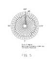
- FIG. 5is a recording of a vertically polarized principle plane radiation pattern of the multi-band antenna of FIG. 1 operating at a frequency of 2.484 GHz.
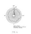
- FIG. 6is a recording of a horizontally polarized principle plane radiation pattern of the multi-band antenna of FIG. 1 operating at a frequency of 5.35 GHz.
- FIG. 7is a recording of a vertically polarized principle plane radiation pattern of the multi-band antenna of FIG. 1 operating at a frequency of 5.35 GHz.
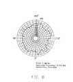
- FIG. 8is a recording of a horizontally polarized principle plane radiation pattern of the multi-band antenna of FIG. 1 operating at a frequency of 5.725 GHz.
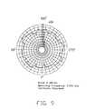
- FIG. 9is a recording of a vertically polarized principle plane radiation pattern of the multi-band antenna of FIG. 1 operating at a frequency of 5.725 GHz.
- a multi-band antenna 1in accordance with a preferred embodiment of the present invention comprises an insulative planar base 30 , a ground patch 10 , a first radiating patch 21 , a second radiating patch 22 , a connecting patch 23 and a signal feeder cable 40 .
- the ground patch 10 , the first radiating patch 21 , the second radiating patch 22 and the connecting patch 23are made from conductive sheet metal, are arranged on a same surface of the insulative planar base 30 , and electrically connect with one another.
- the connecting patch 23connects at a first end to the ground patch 10 , at a medial portion to a first end of the first radiating patch 21 , and at a second end to a medial portion of the second radiating patch 22 .
- a second end of the first radiating patch 21connects with a first end of the second radiating patch 22
- a second end of the second radiating patch 22is a free end and extends parallel to the ground patch 10 .
- the signal feeder cable 40is a coaxial cable and comprises a conductive inner core 42 , a dielectric layer (not labeled), a conductive outer shield 41 over the dielectric layer, and an outer jacket (not labeled).
- the inner core 42is soldered onto a top surface of a connecting point of the first radiating patch 21 and the second radiating patch 22
- the outer shield 41is soldered onto a top surface of the ground patch 10 .
- the inner core 42 , the first radiating patch 21 , the connecting patch 23 , the ground patch 10 and the outer shield 41connect in turn to form a loop antenna for receiving or transmitting higher frequency signals.
- the second radiating patch 22 , the connecting patch 23 , the ground patch 10 and the feeder cable 40connect to form a planar inverted-F antenna (PIFA) for receiving or transmitting lower frequency signals.
- PIFAplanar inverted-F antenna
- multi-band antenna 1major dimensions of the multi-band antenna 1 are labeled thereon, wherein all dimensions are in millimeters (mm).
- the multi-band antenna 1is assembled in an electronic device (e.g. a laptop computer, not shown) by the insulative planar base 30 .
- the ground patch 10is grounded.
- RF signalsare fed to the multi-band antenna 1 by the conductive inner core 42 of the feeder cable 40 and the conductive outer shield 41 .
- FIG. 3shows a test chart recording of Voltage Standing Wave Ratio (VSWR) of the multi-band antenna 1 as a function of frequency. Note that VSWR drops below the desirable maximum value “2” in the 2.3-2.725 GHz frequency band and in the 4.85-5.975 GHz frequency band, indicating acceptably efficient operation in these two wide frequency bands, which cover more than the total bandwidth of the 802.11a and 802.11b standards.
- VSWRVoltage Standing Wave Ratio
- FIGS. 4-9respectively show horizontally and vertically polarized principle plane radiation patterns of the multi-band antenna 1 operating at frequencies of 2.484 GHz, 5.35 GHz, and 5.725 GHz. Note that each radiation pattern is close to a corresponding optimal radiation pattern and there is no obvious radiating blind area.
- the location of the solder point of the inner core 42 on the first radiating patch 21 and the second radiating patch 22is predetermined to achieve a desired matching impedance and an optimal VSWR for both bands. Additionally, the resonance point of the multi-band antenna 1 can be adjusted by changing the dimensions of the first radiating patch 21 or the second radiating patch 2 , or changing the location of the solder point of the inner core 42 .
- the high frequency resonance point of the multi-band antenna 1will move to higher frequency and the low frequency resonance point will move to lower frequency; when the location of the solder point of the inner core 42 moves to the second radiating patch 22 , the high frequency resonance point of the multi-band antenna 1 will move to lower frequency and the low frequency resonance point will move to higher frequency
Landscapes
- Engineering & Computer Science (AREA)
- Computer Networks & Wireless Communication (AREA)
- Waveguide Aerials (AREA)
Abstract
Description
This present application is related to a other two patent applications commonly entitled “MULTI-BAND ANTENNA”, invented by the same inventors, and assigned to a common assignee.
1. Field of the Invention
The present invention relates to an antenna, and in particular to a multi-band antenna employed in a mobile electronic device.
2. Description of the Prior Art
In 1999, the wireless local area network (WLAN) market saw the introduction of the 2.4 GHz IEEE 802.11b standard. Today 802.11b and IEEE 802.11a are among several technologies competing for market leadership and dominance.
The wireless 802.11a standard for WLAN runs in the 5 GHz spectrum, from 5.15-5.825 GHz. 802.11a utilizes the 300 MHz of bandwidth in the 5 GHz Unlicensed National Information Infrastructure (U-NII) band. Although the lower 200 MHz is physically contiguous, the Federal Communications Commission (FCC) has divided the total 300 MHz into three distinct 100 MHz realms; low (5.15-5.25 GHz), middle (5.25-5.35 GHz) and high (5.725-5.825 GHz), each with a different legal maximum power output in the U.S.
802.11a/b dual-mode WLAN products are becoming more prevalent up in the market, so there is a growing need for dual-band antennas for use in such products to adapt them for dual-mode operation. A dual-band planar inverted-F antenna (PIFA) is a good miniaturized built-in antenna for mobile electronic products. However, the bandwidth of the conventional dual-band PIFA antenna is not wide enough to cover the total bandwidth of 802.11a and 802.11b. Generally, because of this narrowband characteristic, the bandwidth of the dual-band PIFA can only cover the bandwidth of 802.11b and one or two bands of 802.11a.
One solution to the above problem is to combine two, or more than two, types of antennas. For example, U.S. Pat. No. 6,204,819 B1 discloses an antenna combining a PIFA and a loop antenna, which are selected by a plurality of switches. Though this antenna can achieve wider bandwidth by adjusting the parameters of the loop antenna, the tridimensional structure of this antenna occupies more space in an electronic device, and the employment of those switches increases the complexity and the cost of this antenna.
Hence, an improved antenna is desired to overcome the above-mentioned shortcomings of existing antennas.
A primary object, therefore, of the present invention is to provide a multi-band antenna combining two different types of antennas for operating in different frequency bands.
A multi-band antenna in accordance with the present invention for an electronic device includes a ground patch, a first radiating patch, a second radiating patch, a connecting patch connecting the first and second radiating patches with the ground patch, and a feeder cable. The multi-band antenna further comprises an insulative planar base, and the ground patch, the first radiating patch, the second radiating patch and the connecting patch are made of thin sheet metal and are arranged on a same surface of the insulative planar base. The ground patch, the connecting patch, the second radiating patch and the feeder cable form a planar inverted-F antenna (PIFA) for receiving or transmitting lower frequency signals, while the first radiating patch, the connecting patch, the ground patch and the feeder cable form a loop antenna for receiving or transmitting higher frequency signals.
Other objects, advantages and novel features of the invention will become more apparent from the following detailed description of a preferred embodiment when taken in conjunction with the accompanying drawings.
Reference will now be made in detail to a preferred embodiment of the present invention.
Referring toFIG. 1 , amulti-band antenna 1 in accordance with a preferred embodiment of the present invention comprises aninsulative planar base 30, aground patch 10, a first radiatingpatch 21, a second radiatingpatch 22, a connectingpatch 23 and a signal feeder cable40.
Theground patch 10, the first radiatingpatch 21, the second radiatingpatch 22 and the connectingpatch 23 are made from conductive sheet metal, are arranged on a same surface of theinsulative planar base 30, and electrically connect with one another. The connectingpatch 23 connects at a first end to theground patch 10, at a medial portion to a first end of the first radiatingpatch 21, and at a second end to a medial portion of the second radiatingpatch 22. A second end of the first radiatingpatch 21 connects with a first end of the second radiatingpatch 22, and a second end of the second radiatingpatch 22 is a free end and extends parallel to theground patch 10.
The signal feeder cable40 is a coaxial cable and comprises a conductiveinner core 42, a dielectric layer (not labeled), a conductiveouter shield 41 over the dielectric layer, and an outer jacket (not labeled). Theinner core 42 is soldered onto a top surface of a connecting point of the first radiatingpatch 21 and the second radiatingpatch 22, and theouter shield 41 is soldered onto a top surface of theground patch 10.
Theinner core 42, the first radiatingpatch 21, the connectingpatch 23, theground patch 10 and theouter shield 41 connect in turn to form a loop antenna for receiving or transmitting higher frequency signals. The second radiatingpatch 22, the connectingpatch 23, theground patch 10 and the feeder cable40 connect to form a planar inverted-F antenna (PIFA) for receiving or transmitting lower frequency signals.
Referring toFIG. 2 , major dimensions of themulti-band antenna 1 are labeled thereon, wherein all dimensions are in millimeters (mm).
In assembly, themulti-band antenna 1 is assembled in an electronic device (e.g. a laptop computer, not shown) by theinsulative planar base 30. Theground patch 10 is grounded. RF signals are fed to themulti-band antenna 1 by the conductiveinner core 42 of the feeder cable40 and the conductiveouter shield 41.
The location of the solder point of theinner core 42 on the first radiatingpatch 21 and the second radiatingpatch 22 is predetermined to achieve a desired matching impedance and an optimal VSWR for both bands. Additionally, the resonance point of themulti-band antenna 1 can be adjusted by changing the dimensions of the first radiatingpatch 21 or the second radiatingpatch 2, or changing the location of the solder point of theinner core 42. For example, when the location of the solder point of theinner core 42 moves to the first radiatingpatch 21, the high frequency resonance point of themulti-band antenna 1 will move to higher frequency and the low frequency resonance point will move to lower frequency; when the location of the solder point of theinner core 42 moves to the second radiatingpatch 22, the high frequency resonance point of themulti-band antenna 1 will move to lower frequency and the low frequency resonance point will move to higher frequency
It is to be understood, however, that even though numerous characteristics and advantages of the present invention have been set forth in the foregoing description, together with details of the structure and function of the invention, the disclosure is illustrative only, and changes may be made in detail, especially in matters of shape, size, and arrangement of parts within the principles of the invention to the full extent indicated by the broad general meaning of the terms in which the appended claims are expressed.
Claims (13)
1. A multi-band antenna for an electronic device, comprising:
a ground patch;
a first radiating patch;
a second radiating patch;
a connecting patch connecting the first and second radiating patches with the ground patch; and
a feeder cable;
wherein the first radiating patch comprises a first end connected to the connecting patch and a second end connected to a first end of the second radiating patch.
2. The multi-band antenna as claimed inclaim 1 , wherein the connecting patch connects at a first end to the ground patch, at a medial portion to the first end of the first radiating patch, and at a second end to a medial portion of the second radiating patch.
3. The multi-band antenna as claimed inclaim 1 , wherein a second end of the second radiating patch is a free end and extends parallel to the grounding patch.
4. The multi-band antenna as claimed inclaim 1 , wherein the feeder cable is a coaxial cable feeder and comprises a conductive inner core wire and a conductive outer shield.
5. The multi-band antenna as claimed inclaim 4 , wherein the inner core wire is electrically connected to the connecting portion of the first radiating patch and the second radiating patch, and the outer shield is electrically connected to the ground patch.
6. The multi-band antenna as claimed inclaim 1 , further comprising an insulative planar base, wherein the ground patch, the first radiating patch, the second radiating patch and the connecting patch are arranged on a same surface of the insulative planer base.
7. The multi-band antenna as claimed inclaim 1 , wherein the ground patch, the connecting patch, the second radiating patch and the feeder cable form a planar inverted-F antenna (PIFA), and the first radiating patch, the connecting patch, the ground patch and the feeder cable form a loop antenna.
8. A multi-band antenna for an electronic device, comprising:
a generally planar inverted-F antenna (PIFA) comprising a radiating patch and a ground patch which are substantially arranged in a plane;
a loop antenna, arranged in the same plane with the inverted-F antenna (PIFA); and
a feeder cable to feed both the PIFA and the loop antenna.
9. The multi-band antenna as claimed inclaim 8 , wherein the PIFA operates in a lower frequency band, and the loop antenna operates in a higher frequency band.
10. A substrate multi-band antenna for an electronic device, comprising:
a cable including an inner core and a grounding braiding surrounding said inner core;
first and second radiating patches extending oppositely by two sides of said cable;
a ground patch spaced from both said first and second radiating patches; and
a connecting patch respectively connecting said first radiating patch and said second radiating patch to the ground patch; wherein
the inner core is connected to an junction of said first radiating patch and said second radiating patch, and the grounding braiding is connected to the ground patch.
11. The antenna as claimed inclaim 10 , wherein a portion of a connection path provided by the connecting patch from the second radiating patch to the ground patch, is same as that provided by the connecting patch from the first radiating patch to the ground patch.
12. The antenna as claimed inclaim 10 , wherein a distance between the first radiating patch and the ground patch, is different from that between the second radiating patch and the ground patch.
13. The antenna as claimed inclaim 10 , wherein said first radiating patch is of straight line while the second radiating patch includes two turns.
Applications Claiming Priority (2)
| Application Number | Priority Date | Filing Date | Title |
|---|---|---|---|
| TW91218157 | 2002-11-13 | ||
| TW091218157UTW549620U (en) | 2002-11-13 | 2002-11-13 | Multi-band antenna |
Publications (2)
| Publication Number | Publication Date |
|---|---|
| US20040090374A1 US20040090374A1 (en) | 2004-05-13 |
| US6897810B2true US6897810B2 (en) | 2005-05-24 |
Family
ID=29998500
Family Applications (1)
| Application Number | Title | Priority Date | Filing Date |
|---|---|---|---|
| US10/315,687Expired - Fee RelatedUS6897810B2 (en) | 2002-11-13 | 2002-12-09 | Multi-band antenna |
Country Status (2)
| Country | Link |
|---|---|
| US (1) | US6897810B2 (en) |
| TW (1) | TW549620U (en) |
Cited By (62)
| Publication number | Priority date | Publication date | Assignee | Title |
|---|---|---|---|---|
| US20030227351A1 (en)* | 2002-05-15 | 2003-12-11 | Hrl Laboratories, Llc | Single-pole multi-throw switch having low parasitic reactance, and an antenna incorporating the same |
| US20040135649A1 (en)* | 2002-05-15 | 2004-07-15 | Sievenpiper Daniel F | Single-pole multi-throw switch having low parasitic reactance, and an antenna incorporating the same |
| US20040227678A1 (en)* | 2003-05-12 | 2004-11-18 | Hrl Laboratories, Llc | Compact tunable antenna |
| US20040227583A1 (en)* | 2003-05-12 | 2004-11-18 | Hrl Laboratories, Llc | RF MEMS switch with integrated impedance matching structure |
| US20040227667A1 (en)* | 2003-05-12 | 2004-11-18 | Hrl Laboratories, Llc | Meta-element antenna and array |
| US20040263408A1 (en)* | 2003-05-12 | 2004-12-30 | Hrl Laboratories, Llc | Adaptive beam forming antenna system using a tunable impedance surface |
| US20050068234A1 (en)* | 2003-09-26 | 2005-03-31 | Hung Zhen Da | Multi-band antenna |
| US20060109179A1 (en)* | 2003-04-28 | 2006-05-25 | Harald Humpfer | Antenna device |
| US7071888B2 (en) | 2003-05-12 | 2006-07-04 | Hrl Laboratories, Llc | Steerable leaky wave antenna capable of both forward and backward radiation |
| US7154451B1 (en) | 2004-09-17 | 2006-12-26 | Hrl Laboratories, Llc | Large aperture rectenna based on planar lens structures |
| US20070018892A1 (en)* | 2005-07-22 | 2007-01-25 | Hon Hai Precision Ind. Co., Ltd. | Planar inverted F antenna and method of making the same |
| US20070103370A1 (en)* | 2005-11-04 | 2007-05-10 | Hon Hai Precision Ind. Co., Ltd. | Multi-band antenna |
| US20070132641A1 (en)* | 2003-10-31 | 2007-06-14 | Lk Products Oy | Multiband planar antenna |
| US7307589B1 (en) | 2005-12-29 | 2007-12-11 | Hrl Laboratories, Llc | Large-scale adaptive surface sensor arrays |
| US7391375B1 (en)* | 2007-02-16 | 2008-06-24 | Cheng Uei Precision Industry Co., Ltd. | Multi-band antenna |
| US7456803B1 (en) | 2003-05-12 | 2008-11-25 | Hrl Laboratories, Llc | Large aperture rectenna based on planar lens structures |
| US20080303731A1 (en)* | 2007-06-07 | 2008-12-11 | Hsin-Tsung Wu | Multi-band antenna |
| US20090135072A1 (en)* | 2007-11-26 | 2009-05-28 | Hon Hai Precision Ind.Co., Ltd. | Multi-band antenna |
| US20090231230A1 (en)* | 2008-03-17 | 2009-09-17 | Hon Hai Precision Industry Co., Ltd. | Multi-band antenna with improved connecting portion |
| US20100085259A1 (en)* | 2008-10-07 | 2010-04-08 | Ralink Technology Corporation | Planar antenna |
| US20100127941A1 (en)* | 2008-11-21 | 2010-05-27 | Yuh-Yuh Chiang | Wireless signal antenna |
| US7868829B1 (en) | 2008-03-21 | 2011-01-11 | Hrl Laboratories, Llc | Reflectarray |
| US20110068983A1 (en)* | 2009-09-18 | 2011-03-24 | Aisin Seiki Kabushiki Kaisha | Multi-frequency antenna |
| US20110127336A1 (en)* | 2008-08-19 | 2011-06-02 | Murata Manufacturing Co., Ltd. | Wireless ic device and method for manufacturing same |
| US8436785B1 (en) | 2010-11-03 | 2013-05-07 | Hrl Laboratories, Llc | Electrically tunable surface impedance structure with suppressed backward wave |
| US8466756B2 (en) | 2007-04-19 | 2013-06-18 | Pulse Finland Oy | Methods and apparatus for matching an antenna |
| US8473017B2 (en) | 2005-10-14 | 2013-06-25 | Pulse Finland Oy | Adjustable antenna and methods |
| US8564485B2 (en) | 2005-07-25 | 2013-10-22 | Pulse Finland Oy | Adjustable multiband antenna and methods |
| US8618990B2 (en) | 2011-04-13 | 2013-12-31 | Pulse Finland Oy | Wideband antenna and methods |
| US8629813B2 (en) | 2007-08-30 | 2014-01-14 | Pusle Finland Oy | Adjustable multi-band antenna and methods |
| US8648752B2 (en) | 2011-02-11 | 2014-02-11 | Pulse Finland Oy | Chassis-excited antenna apparatus and methods |
| US8786499B2 (en) | 2005-10-03 | 2014-07-22 | Pulse Finland Oy | Multiband antenna system and methods |
| US8847833B2 (en) | 2009-12-29 | 2014-09-30 | Pulse Finland Oy | Loop resonator apparatus and methods for enhanced field control |
| US8866689B2 (en) | 2011-07-07 | 2014-10-21 | Pulse Finland Oy | Multi-band antenna and methods for long term evolution wireless system |
| US8982011B1 (en) | 2011-09-23 | 2015-03-17 | Hrl Laboratories, Llc | Conformal antennas for mitigation of structural blockage |
| US8988296B2 (en) | 2012-04-04 | 2015-03-24 | Pulse Finland Oy | Compact polarized antenna and methods |
| US8994609B2 (en) | 2011-09-23 | 2015-03-31 | Hrl Laboratories, Llc | Conformal surface wave feed |
| US9123990B2 (en) | 2011-10-07 | 2015-09-01 | Pulse Finland Oy | Multi-feed antenna apparatus and methods |
| US20150325915A1 (en)* | 2014-05-09 | 2015-11-12 | Universal Scientific Industrial (Shanghai) Co., Ltd. | Multi-band antenna |
| US9203154B2 (en) | 2011-01-25 | 2015-12-01 | Pulse Finland Oy | Multi-resonance antenna, antenna module, radio device and methods |
| US9246210B2 (en) | 2010-02-18 | 2016-01-26 | Pulse Finland Oy | Antenna with cover radiator and methods |
| US9350081B2 (en) | 2014-01-14 | 2016-05-24 | Pulse Finland Oy | Switchable multi-radiator high band antenna apparatus |
| US9406998B2 (en) | 2010-04-21 | 2016-08-02 | Pulse Finland Oy | Distributed multiband antenna and methods |
| US9450291B2 (en) | 2011-07-25 | 2016-09-20 | Pulse Finland Oy | Multiband slot loop antenna apparatus and methods |
| US9461371B2 (en) | 2009-11-27 | 2016-10-04 | Pulse Finland Oy | MIMO antenna and methods |
| US9466887B2 (en) | 2010-11-03 | 2016-10-11 | Hrl Laboratories, Llc | Low cost, 2D, electronically-steerable, artificial-impedance-surface antenna |
| US9484619B2 (en) | 2011-12-21 | 2016-11-01 | Pulse Finland Oy | Switchable diversity antenna apparatus and methods |
| US9531058B2 (en) | 2011-12-20 | 2016-12-27 | Pulse Finland Oy | Loosely-coupled radio antenna apparatus and methods |
| US9590308B2 (en) | 2013-12-03 | 2017-03-07 | Pulse Electronics, Inc. | Reduced surface area antenna apparatus and mobile communications devices incorporating the same |
| US9634383B2 (en) | 2013-06-26 | 2017-04-25 | Pulse Finland Oy | Galvanically separated non-interacting antenna sector apparatus and methods |
| US9647338B2 (en) | 2013-03-11 | 2017-05-09 | Pulse Finland Oy | Coupled antenna structure and methods |
| US9673507B2 (en) | 2011-02-11 | 2017-06-06 | Pulse Finland Oy | Chassis-excited antenna apparatus and methods |
| US9680212B2 (en) | 2013-11-20 | 2017-06-13 | Pulse Finland Oy | Capacitive grounding methods and apparatus for mobile devices |
| US9722308B2 (en) | 2014-08-28 | 2017-08-01 | Pulse Finland Oy | Low passive intermodulation distributed antenna system for multiple-input multiple-output systems and methods of use |
| US9761951B2 (en) | 2009-11-03 | 2017-09-12 | Pulse Finland Oy | Adjustable antenna apparatus and methods |
| US9906260B2 (en) | 2015-07-30 | 2018-02-27 | Pulse Finland Oy | Sensor-based closed loop antenna swapping apparatus and methods |
| US9903736B2 (en) | 2014-09-18 | 2018-02-27 | Arad Measuring Technologies Ltd. | Utility meter having a meter register utilizing a multiple resonance antenna |
| US9948002B2 (en) | 2014-08-26 | 2018-04-17 | Pulse Finland Oy | Antenna apparatus with an integrated proximity sensor and methods |
| US9973228B2 (en) | 2014-08-26 | 2018-05-15 | Pulse Finland Oy | Antenna apparatus with an integrated proximity sensor and methods |
| US9979078B2 (en) | 2012-10-25 | 2018-05-22 | Pulse Finland Oy | Modular cell antenna apparatus and methods |
| US10069209B2 (en) | 2012-11-06 | 2018-09-04 | Pulse Finland Oy | Capacitively coupled antenna apparatus and methods |
| US10079428B2 (en) | 2013-03-11 | 2018-09-18 | Pulse Finland Oy | Coupled antenna structure and methods |
Families Citing this family (8)
| Publication number | Priority date | Publication date | Assignee | Title |
|---|---|---|---|---|
| TW583785B (en)* | 2003-04-08 | 2004-04-11 | Yageo Corp | Integrated antenna for portable computer |
| TWI243512B (en)* | 2003-11-18 | 2005-11-11 | Hon Hai Prec Ind Co Ltd | Planar inverted-f antenna and method of manufacturing of the same |
| US7307591B2 (en)* | 2004-07-20 | 2007-12-11 | Nokia Corporation | Multi-band antenna |
| US20060089108A1 (en)* | 2004-10-26 | 2006-04-27 | Isaac Lagnado | Mechanical latch including RF antenna |
| US9136594B2 (en)* | 2009-08-20 | 2015-09-15 | Qualcomm Incorporated | Compact multi-band planar inverted F antenna |
| US8644894B2 (en) | 2010-03-12 | 2014-02-04 | Blackberry Limited | Mobile wireless device with multi-band antenna and related methods |
| TWI543444B (en)* | 2012-08-20 | 2016-07-21 | 鴻海精密工業股份有限公司 | Dual-band planar inverted-f antenna |
| US10431885B2 (en)* | 2016-09-19 | 2019-10-01 | Wistron Neweb Corporation | Antenna system and antenna structure thereof |
Citations (7)
| Publication number | Priority date | Publication date | Assignee | Title |
|---|---|---|---|---|
| US6002367A (en) | 1996-05-17 | 1999-12-14 | Allgon Ab | Planar antenna device |
| US6072434A (en) | 1997-02-04 | 2000-06-06 | Lucent Technologies Inc. | Aperture-coupled planar inverted-F antenna |
| US6204819B1 (en) | 2000-05-22 | 2001-03-20 | Telefonaktiebolaget L.M. Ericsson | Convertible loop/inverted-f antennas and wireless communicators incorporating the same |
| US6346914B1 (en)* | 1999-08-25 | 2002-02-12 | Filtronic Lk Oy | Planar antenna structure |
| US20030107518A1 (en)* | 2001-12-12 | 2003-06-12 | Li Ronglin | Folded shorted patch antenna |
| US20030201942A1 (en)* | 2002-04-25 | 2003-10-30 | Ethertronics, Inc. | Low-profile, multi-frequency, multi-band, capacitively loaded magnetic dipole antenna |
| US20040017319A1 (en)* | 2002-07-24 | 2004-01-29 | Phycomp Taiwan Ltd. | Integrated antenna for portable computer |
- 2002
- 2002-11-13TWTW091218157Upatent/TW549620U/enunknown
- 2002-12-09USUS10/315,687patent/US6897810B2/ennot_activeExpired - Fee Related
Patent Citations (7)
| Publication number | Priority date | Publication date | Assignee | Title |
|---|---|---|---|---|
| US6002367A (en) | 1996-05-17 | 1999-12-14 | Allgon Ab | Planar antenna device |
| US6072434A (en) | 1997-02-04 | 2000-06-06 | Lucent Technologies Inc. | Aperture-coupled planar inverted-F antenna |
| US6346914B1 (en)* | 1999-08-25 | 2002-02-12 | Filtronic Lk Oy | Planar antenna structure |
| US6204819B1 (en) | 2000-05-22 | 2001-03-20 | Telefonaktiebolaget L.M. Ericsson | Convertible loop/inverted-f antennas and wireless communicators incorporating the same |
| US20030107518A1 (en)* | 2001-12-12 | 2003-06-12 | Li Ronglin | Folded shorted patch antenna |
| US20030201942A1 (en)* | 2002-04-25 | 2003-10-30 | Ethertronics, Inc. | Low-profile, multi-frequency, multi-band, capacitively loaded magnetic dipole antenna |
| US20040017319A1 (en)* | 2002-07-24 | 2004-01-29 | Phycomp Taiwan Ltd. | Integrated antenna for portable computer |
Non-Patent Citations (1)
| Title |
|---|
| Fang-I Hsu, "Planar Near-Field to Far-Field Transformation and PIFA Antenna Suitable for Wireless LAN", Paper of Institute of Communication Engineering National Chiao Tung University of Taiwan, 2001, http//datas.ncl.edu.tw/. |
Cited By (80)
| Publication number | Priority date | Publication date | Assignee | Title |
|---|---|---|---|---|
| US20040135649A1 (en)* | 2002-05-15 | 2004-07-15 | Sievenpiper Daniel F | Single-pole multi-throw switch having low parasitic reactance, and an antenna incorporating the same |
| US20030227351A1 (en)* | 2002-05-15 | 2003-12-11 | Hrl Laboratories, Llc | Single-pole multi-throw switch having low parasitic reactance, and an antenna incorporating the same |
| US7298228B2 (en) | 2002-05-15 | 2007-11-20 | Hrl Laboratories, Llc | Single-pole multi-throw switch having low parasitic reactance, and an antenna incorporating the same |
| US7276990B2 (en) | 2002-05-15 | 2007-10-02 | Hrl Laboratories, Llc | Single-pole multi-throw switch having low parasitic reactance, and an antenna incorporating the same |
| US20060109179A1 (en)* | 2003-04-28 | 2006-05-25 | Harald Humpfer | Antenna device |
| US7218282B2 (en)* | 2003-04-28 | 2007-05-15 | Fraunhofer-Gesellschaft Zur Foerderung Der Angewandten Forschung E.V. | Antenna device |
| US7253699B2 (en) | 2003-05-12 | 2007-08-07 | Hrl Laboratories, Llc | RF MEMS switch with integrated impedance matching structure |
| US20040227667A1 (en)* | 2003-05-12 | 2004-11-18 | Hrl Laboratories, Llc | Meta-element antenna and array |
| US20040227678A1 (en)* | 2003-05-12 | 2004-11-18 | Hrl Laboratories, Llc | Compact tunable antenna |
| US7068234B2 (en) | 2003-05-12 | 2006-06-27 | Hrl Laboratories, Llc | Meta-element antenna and array |
| US7071888B2 (en) | 2003-05-12 | 2006-07-04 | Hrl Laboratories, Llc | Steerable leaky wave antenna capable of both forward and backward radiation |
| US20040227583A1 (en)* | 2003-05-12 | 2004-11-18 | Hrl Laboratories, Llc | RF MEMS switch with integrated impedance matching structure |
| US7164387B2 (en)* | 2003-05-12 | 2007-01-16 | Hrl Laboratories, Llc | Compact tunable antenna |
| US7456803B1 (en) | 2003-05-12 | 2008-11-25 | Hrl Laboratories, Llc | Large aperture rectenna based on planar lens structures |
| US7245269B2 (en) | 2003-05-12 | 2007-07-17 | Hrl Laboratories, Llc | Adaptive beam forming antenna system using a tunable impedance surface |
| US20040263408A1 (en)* | 2003-05-12 | 2004-12-30 | Hrl Laboratories, Llc | Adaptive beam forming antenna system using a tunable impedance surface |
| US7034754B2 (en)* | 2003-09-26 | 2006-04-25 | Hon Hai Precision Ind. Co., Ltd. | Multi-band antenna |
| US20050068234A1 (en)* | 2003-09-26 | 2005-03-31 | Hung Zhen Da | Multi-band antenna |
| US20070132641A1 (en)* | 2003-10-31 | 2007-06-14 | Lk Products Oy | Multiband planar antenna |
| US7352326B2 (en)* | 2003-10-31 | 2008-04-01 | Lk Products Oy | Multiband planar antenna |
| US7154451B1 (en) | 2004-09-17 | 2006-12-26 | Hrl Laboratories, Llc | Large aperture rectenna based on planar lens structures |
| US20070018892A1 (en)* | 2005-07-22 | 2007-01-25 | Hon Hai Precision Ind. Co., Ltd. | Planar inverted F antenna and method of making the same |
| US7375686B2 (en)* | 2005-07-22 | 2008-05-20 | Hon Hai Precision Ind. Co., Ltd. | Planar inverted F antenna and method of making the same |
| US8564485B2 (en) | 2005-07-25 | 2013-10-22 | Pulse Finland Oy | Adjustable multiband antenna and methods |
| US8786499B2 (en) | 2005-10-03 | 2014-07-22 | Pulse Finland Oy | Multiband antenna system and methods |
| US8473017B2 (en) | 2005-10-14 | 2013-06-25 | Pulse Finland Oy | Adjustable antenna and methods |
| US20070103370A1 (en)* | 2005-11-04 | 2007-05-10 | Hon Hai Precision Ind. Co., Ltd. | Multi-band antenna |
| US7339536B2 (en)* | 2005-11-04 | 2008-03-04 | Hon Hai Precision Ind. Co., Ltd. | Multi-band antenna |
| US7307589B1 (en) | 2005-12-29 | 2007-12-11 | Hrl Laboratories, Llc | Large-scale adaptive surface sensor arrays |
| US7391375B1 (en)* | 2007-02-16 | 2008-06-24 | Cheng Uei Precision Industry Co., Ltd. | Multi-band antenna |
| US8466756B2 (en) | 2007-04-19 | 2013-06-18 | Pulse Finland Oy | Methods and apparatus for matching an antenna |
| US20080303731A1 (en)* | 2007-06-07 | 2008-12-11 | Hsin-Tsung Wu | Multi-band antenna |
| US7482986B2 (en)* | 2007-06-07 | 2009-01-27 | Cheng Uei Precision Industry Co., Ltd. | Multi-band antenna |
| US8629813B2 (en) | 2007-08-30 | 2014-01-14 | Pusle Finland Oy | Adjustable multi-band antenna and methods |
| US8144062B2 (en)* | 2007-11-26 | 2012-03-27 | Hon Hai Precision Ind. Co., Ltd. | Multi-band antenna |
| US20090135072A1 (en)* | 2007-11-26 | 2009-05-28 | Hon Hai Precision Ind.Co., Ltd. | Multi-band antenna |
| US20090231230A1 (en)* | 2008-03-17 | 2009-09-17 | Hon Hai Precision Industry Co., Ltd. | Multi-band antenna with improved connecting portion |
| US7868829B1 (en) | 2008-03-21 | 2011-01-11 | Hrl Laboratories, Llc | Reflectarray |
| US20110127336A1 (en)* | 2008-08-19 | 2011-06-02 | Murata Manufacturing Co., Ltd. | Wireless ic device and method for manufacturing same |
| US8870077B2 (en)* | 2008-08-19 | 2014-10-28 | Murata Manufacturing Co., Ltd. | Wireless IC device and method for manufacturing same |
| US20100085259A1 (en)* | 2008-10-07 | 2010-04-08 | Ralink Technology Corporation | Planar antenna |
| US20100127941A1 (en)* | 2008-11-21 | 2010-05-27 | Yuh-Yuh Chiang | Wireless signal antenna |
| US8390517B2 (en)* | 2008-11-21 | 2013-03-05 | Wistron Neweb Corp. | Wireless signal antenna |
| US20110068983A1 (en)* | 2009-09-18 | 2011-03-24 | Aisin Seiki Kabushiki Kaisha | Multi-frequency antenna |
| US9761951B2 (en) | 2009-11-03 | 2017-09-12 | Pulse Finland Oy | Adjustable antenna apparatus and methods |
| US9461371B2 (en) | 2009-11-27 | 2016-10-04 | Pulse Finland Oy | MIMO antenna and methods |
| US8847833B2 (en) | 2009-12-29 | 2014-09-30 | Pulse Finland Oy | Loop resonator apparatus and methods for enhanced field control |
| US9246210B2 (en) | 2010-02-18 | 2016-01-26 | Pulse Finland Oy | Antenna with cover radiator and methods |
| US9406998B2 (en) | 2010-04-21 | 2016-08-02 | Pulse Finland Oy | Distributed multiband antenna and methods |
| US9466887B2 (en) | 2010-11-03 | 2016-10-11 | Hrl Laboratories, Llc | Low cost, 2D, electronically-steerable, artificial-impedance-surface antenna |
| US8436785B1 (en) | 2010-11-03 | 2013-05-07 | Hrl Laboratories, Llc | Electrically tunable surface impedance structure with suppressed backward wave |
| US9203154B2 (en) | 2011-01-25 | 2015-12-01 | Pulse Finland Oy | Multi-resonance antenna, antenna module, radio device and methods |
| US9917346B2 (en) | 2011-02-11 | 2018-03-13 | Pulse Finland Oy | Chassis-excited antenna apparatus and methods |
| US9673507B2 (en) | 2011-02-11 | 2017-06-06 | Pulse Finland Oy | Chassis-excited antenna apparatus and methods |
| US8648752B2 (en) | 2011-02-11 | 2014-02-11 | Pulse Finland Oy | Chassis-excited antenna apparatus and methods |
| US8618990B2 (en) | 2011-04-13 | 2013-12-31 | Pulse Finland Oy | Wideband antenna and methods |
| US8866689B2 (en) | 2011-07-07 | 2014-10-21 | Pulse Finland Oy | Multi-band antenna and methods for long term evolution wireless system |
| US9450291B2 (en) | 2011-07-25 | 2016-09-20 | Pulse Finland Oy | Multiband slot loop antenna apparatus and methods |
| US8994609B2 (en) | 2011-09-23 | 2015-03-31 | Hrl Laboratories, Llc | Conformal surface wave feed |
| US8982011B1 (en) | 2011-09-23 | 2015-03-17 | Hrl Laboratories, Llc | Conformal antennas for mitigation of structural blockage |
| US9123990B2 (en) | 2011-10-07 | 2015-09-01 | Pulse Finland Oy | Multi-feed antenna apparatus and methods |
| US9531058B2 (en) | 2011-12-20 | 2016-12-27 | Pulse Finland Oy | Loosely-coupled radio antenna apparatus and methods |
| US9484619B2 (en) | 2011-12-21 | 2016-11-01 | Pulse Finland Oy | Switchable diversity antenna apparatus and methods |
| US8988296B2 (en) | 2012-04-04 | 2015-03-24 | Pulse Finland Oy | Compact polarized antenna and methods |
| US9509054B2 (en) | 2012-04-04 | 2016-11-29 | Pulse Finland Oy | Compact polarized antenna and methods |
| US9979078B2 (en) | 2012-10-25 | 2018-05-22 | Pulse Finland Oy | Modular cell antenna apparatus and methods |
| US10069209B2 (en) | 2012-11-06 | 2018-09-04 | Pulse Finland Oy | Capacitively coupled antenna apparatus and methods |
| US10079428B2 (en) | 2013-03-11 | 2018-09-18 | Pulse Finland Oy | Coupled antenna structure and methods |
| US9647338B2 (en) | 2013-03-11 | 2017-05-09 | Pulse Finland Oy | Coupled antenna structure and methods |
| US9634383B2 (en) | 2013-06-26 | 2017-04-25 | Pulse Finland Oy | Galvanically separated non-interacting antenna sector apparatus and methods |
| US9680212B2 (en) | 2013-11-20 | 2017-06-13 | Pulse Finland Oy | Capacitive grounding methods and apparatus for mobile devices |
| US9590308B2 (en) | 2013-12-03 | 2017-03-07 | Pulse Electronics, Inc. | Reduced surface area antenna apparatus and mobile communications devices incorporating the same |
| US9350081B2 (en) | 2014-01-14 | 2016-05-24 | Pulse Finland Oy | Switchable multi-radiator high band antenna apparatus |
| US20150325915A1 (en)* | 2014-05-09 | 2015-11-12 | Universal Scientific Industrial (Shanghai) Co., Ltd. | Multi-band antenna |
| US9461362B2 (en)* | 2014-05-09 | 2016-10-04 | Universal Scientific Industrial (Shanghai) Co., Ltd. | Multi-band antenna |
| US9948002B2 (en) | 2014-08-26 | 2018-04-17 | Pulse Finland Oy | Antenna apparatus with an integrated proximity sensor and methods |
| US9973228B2 (en) | 2014-08-26 | 2018-05-15 | Pulse Finland Oy | Antenna apparatus with an integrated proximity sensor and methods |
| US9722308B2 (en) | 2014-08-28 | 2017-08-01 | Pulse Finland Oy | Low passive intermodulation distributed antenna system for multiple-input multiple-output systems and methods of use |
| US9903736B2 (en) | 2014-09-18 | 2018-02-27 | Arad Measuring Technologies Ltd. | Utility meter having a meter register utilizing a multiple resonance antenna |
| US9906260B2 (en) | 2015-07-30 | 2018-02-27 | Pulse Finland Oy | Sensor-based closed loop antenna swapping apparatus and methods |
Also Published As
| Publication number | Publication date |
|---|---|
| TW549620U (en) | 2003-08-21 |
| US20040090374A1 (en) | 2004-05-13 |
Similar Documents
| Publication | Publication Date | Title |
|---|---|---|
| US6897810B2 (en) | Multi-band antenna | |
| US7119747B2 (en) | Multi-band antenna | |
| US6734826B1 (en) | Multi-band antenna | |
| US6864841B2 (en) | Multi-band antenna | |
| US7429955B2 (en) | Multi-band antenna | |
| US6864842B2 (en) | Tri-band antenna | |
| US7375686B2 (en) | Planar inverted F antenna and method of making the same | |
| US7034754B2 (en) | Multi-band antenna | |
| US6801169B1 (en) | Multi-band printed monopole antenna | |
| US20040222936A1 (en) | Multi-band dipole antenna | |
| US6844853B2 (en) | Dual band antenna for wireless communication | |
| US6380903B1 (en) | Antenna systems including internal planar inverted-F antennas coupled with retractable antennas and wireless communicators incorporating same | |
| US20050035919A1 (en) | Multi-band printed dipole antenna | |
| US8593354B2 (en) | Multi-band antenna | |
| US7030830B2 (en) | Dual-access monopole antenna assembly | |
| US20060103577A1 (en) | Ultra wideband internal antenna | |
| US20040104849A1 (en) | Dual band antenna | |
| US20020190905A1 (en) | Integrated antenna for laptop applications | |
| US20050259024A1 (en) | Multi-band antenna with wide bandwidth | |
| US7692599B2 (en) | Ultra-wideband shorted dipole antenna | |
| US7095371B2 (en) | Antenna assembly | |
| US20090073050A1 (en) | Dual band antenna | |
| US6897817B2 (en) | Independently tunable multiband meanderline loaded antenna | |
| US7106254B2 (en) | Single-mode antenna assembly | |
| US20080094303A1 (en) | Planer inverted-F antenna device |
Legal Events
| Date | Code | Title | Description |
|---|---|---|---|
| AS | Assignment | Owner name:HON HAI PRECISION IND. CO., LTD., TAIWAN Free format text:ASSIGNMENT OF ASSIGNORS INTEREST;ASSIGNORS:DAI, HSIN KUO;TAI, LUNG SHENG;LIN, HSIEN-CHU;AND OTHERS;REEL/FRAME:013562/0665 Effective date:20021128 | |
| FPAY | Fee payment | Year of fee payment:4 | |
| FPAY | Fee payment | Year of fee payment:8 | |
| REMI | Maintenance fee reminder mailed | ||
| LAPS | Lapse for failure to pay maintenance fees | ||
| STCH | Information on status: patent discontinuation | Free format text:PATENT EXPIRED DUE TO NONPAYMENT OF MAINTENANCE FEES UNDER 37 CFR 1.362 | |
| FP | Lapsed due to failure to pay maintenance fee | Effective date:20170524 |