US6897514B2 - Two mask floating gate EEPROM and method of making - Google Patents
Two mask floating gate EEPROM and method of makingDownload PDFInfo
- Publication number
- US6897514B2 US6897514B2US10/066,376US6637602AUS6897514B2US 6897514 B2US6897514 B2US 6897514B2US 6637602 AUS6637602 AUS 6637602AUS 6897514 B2US6897514 B2US 6897514B2
- Authority
- US
- United States
- Prior art keywords
- floating gate
- layer
- transistor
- control gate
- source
- Prior art date
- Legal status (The legal status is an assumption and is not a legal conclusion. Google has not performed a legal analysis and makes no representation as to the accuracy of the status listed.)
- Expired - Fee Related, expires
Links
- 238000007667floatingMethods0.000titleclaimsabstractdescription110
- 238000004519manufacturing processMethods0.000titleabstractdescription11
- 230000000873masking effectEffects0.000claimsabstractdescription18
- 239000010410layerSubstances0.000claimsdescription181
- 230000015654memoryEffects0.000claimsdescription46
- 239000000758substrateSubstances0.000claimsdescription30
- 229910021420polycrystalline siliconInorganic materials0.000claimsdescription24
- 229920005591polysiliconPolymers0.000claimsdescription21
- 239000004065semiconductorSubstances0.000claimsdescription18
- 125000006850spacer groupChemical group0.000claimsdescription15
- 239000011229interlayerSubstances0.000claimsdescription12
- 229910021332silicideInorganic materials0.000claimsdescription12
- FVBUAEGBCNSCDD-UHFFFAOYSA-Nsilicide(4-)Chemical group[Si-4]FVBUAEGBCNSCDD-UHFFFAOYSA-N0.000claimsdescription12
- 230000005641tunnelingEffects0.000claimsdescription9
- 229910052751metalInorganic materials0.000claimsdescription7
- 239000002184metalSubstances0.000claimsdescription7
- 238000000034methodMethods0.000abstractdescription32
- 229920002120photoresistant polymerPolymers0.000abstractdescription24
- 238000000059patterningMethods0.000abstractdescription9
- VYPSYNLAJGMNEJ-UHFFFAOYSA-NSilicium dioxideChemical compoundO=[Si]=OVYPSYNLAJGMNEJ-UHFFFAOYSA-N0.000description23
- 230000008569processEffects0.000description20
- 229910052814silicon oxideInorganic materials0.000description19
- 229910052710siliconInorganic materials0.000description18
- 239000010703siliconSubstances0.000description18
- XUIMIQQOPSSXEZ-UHFFFAOYSA-NSiliconChemical compound[Si]XUIMIQQOPSSXEZ-UHFFFAOYSA-N0.000description17
- 230000015572biosynthetic processEffects0.000description13
- 229910052581Si3N4Inorganic materials0.000description10
- HQVNEWCFYHHQES-UHFFFAOYSA-Nsilicon nitrideChemical compoundN12[Si]34N5[Si]62N3[Si]51N64HQVNEWCFYHHQES-UHFFFAOYSA-N0.000description10
- 238000005530etchingMethods0.000description8
- 238000003491arrayMethods0.000description7
- 239000002019doping agentSubstances0.000description7
- 238000005468ion implantationMethods0.000description6
- 238000002955isolationMethods0.000description6
- 229910021417amorphous siliconInorganic materials0.000description5
- 238000000151depositionMethods0.000description5
- 230000008021depositionEffects0.000description5
- 238000002513implantationMethods0.000description5
- 238000002425crystallisationMethods0.000description4
- 230000008025crystallizationEffects0.000description4
- 230000007423decreaseEffects0.000description4
- 239000011521glassSubstances0.000description4
- 239000012212insulatorSubstances0.000description4
- 239000000463materialSubstances0.000description4
- 230000003647oxidationEffects0.000description4
- 238000007254oxidation reactionMethods0.000description4
- 238000000137annealingMethods0.000description3
- 239000005380borophosphosilicate glassSubstances0.000description3
- 239000005388borosilicate glassSubstances0.000description3
- 239000003054catalystSubstances0.000description3
- 239000003989dielectric materialSubstances0.000description3
- 229910052760oxygenInorganic materials0.000description3
- 239000001301oxygenSubstances0.000description3
- -1oxygen ionsChemical class0.000description3
- 230000002093peripheral effectEffects0.000description3
- 239000005360phosphosilicate glassSubstances0.000description3
- 238000000206photolithographyMethods0.000description3
- 238000005498polishingMethods0.000description3
- 239000004642PolyimideSubstances0.000description2
- 229910008484TiSiInorganic materials0.000description2
- 230000004913activationEffects0.000description2
- QVGXLLKOCUKJST-UHFFFAOYSA-Natomic oxygenChemical compound[O]QVGXLLKOCUKJST-UHFFFAOYSA-N0.000description2
- 230000008901benefitEffects0.000description2
- 239000000919ceramicSubstances0.000description2
- 239000002800charge carrierSubstances0.000description2
- 230000009977dual effectEffects0.000description2
- 238000010438heat treatmentMethods0.000description2
- 239000007943implantSubstances0.000description2
- 238000002347injectionMethods0.000description2
- 239000007924injectionSubstances0.000description2
- 239000011810insulating materialSubstances0.000description2
- 238000004518low pressure chemical vapour depositionMethods0.000description2
- 229910052750molybdenumInorganic materials0.000description2
- 229910021421monocrystalline siliconInorganic materials0.000description2
- 229910052763palladiumInorganic materials0.000description2
- 239000004033plasticSubstances0.000description2
- 229910052697platinumInorganic materials0.000description2
- 229920001721polyimidePolymers0.000description2
- 229920000642polymerPolymers0.000description2
- 235000012239silicon dioxideNutrition0.000description2
- 239000000377silicon dioxideSubstances0.000description2
- 238000003860storageMethods0.000description2
- 239000010409thin filmSubstances0.000description2
- 229910052719titaniumInorganic materials0.000description2
- 229910052723transition metalInorganic materials0.000description2
- 229910052721tungstenInorganic materials0.000description2
- 241000252506CharaciformesSpecies0.000description1
- 230000005689Fowler Nordheim tunnelingEffects0.000description1
- 229910001218Gallium arsenideInorganic materials0.000description1
- 101100521334Mus musculus Prom1 geneProteins0.000description1
- 229910017920NH3OHInorganic materials0.000description1
- 239000003990capacitorSubstances0.000description1
- 238000006243chemical reactionMethods0.000description1
- 230000000295complement effectEffects0.000description1
- 238000010276constructionMethods0.000description1
- 238000007796conventional methodMethods0.000description1
- 239000013078crystalSubstances0.000description1
- 230000003247decreasing effectEffects0.000description1
- 238000010586diagramMethods0.000description1
- 238000009792diffusion processMethods0.000description1
- 238000009826distributionMethods0.000description1
- 238000005516engineering processMethods0.000description1
- 230000005669field effectEffects0.000description1
- 238000011049fillingMethods0.000description1
- 239000010408filmSubstances0.000description1
- 239000002784hot electronSubstances0.000description1
- 239000012535impuritySubstances0.000description1
- 238000011065in-situ storageMethods0.000description1
- 150000002500ionsChemical class0.000description1
- 238000005224laser annealingMethods0.000description1
- 239000004973liquid crystal related substanceSubstances0.000description1
- 230000007246mechanismEffects0.000description1
- 229910044991metal oxideInorganic materials0.000description1
- 150000004706metal oxidesChemical class0.000description1
- 238000012986modificationMethods0.000description1
- 230000004048modificationEffects0.000description1
- 229910052759nickelInorganic materials0.000description1
- 150000004767nitridesChemical class0.000description1
- 230000003071parasitic effectEffects0.000description1
- 238000001953recrystallisationMethods0.000description1
- 238000007788rougheningMethods0.000description1
- 238000000926separation methodMethods0.000description1
- 239000002356single layerSubstances0.000description1
- 239000007790solid phaseSubstances0.000description1
- 239000000243solutionSubstances0.000description1
- 239000000126substanceSubstances0.000description1
- 229910052715tantalumInorganic materials0.000description1
- 238000012876topographyMethods0.000description1
- 150000003624transition metalsChemical class0.000description1
- 238000001039wet etchingMethods0.000description1
Images


Classifications
- H—ELECTRICITY
- H10—SEMICONDUCTOR DEVICES; ELECTRIC SOLID-STATE DEVICES NOT OTHERWISE PROVIDED FOR
- H10D—INORGANIC ELECTRIC SEMICONDUCTOR DEVICES
- H10D30/00—Field-effect transistors [FET]
- H10D30/60—Insulated-gate field-effect transistors [IGFET]
- H10D30/69—IGFETs having charge trapping gate insulators, e.g. MNOS transistors
- H10D30/693—Vertical IGFETs having charge trapping gate insulators
- H—ELECTRICITY
- H10—SEMICONDUCTOR DEVICES; ELECTRIC SOLID-STATE DEVICES NOT OTHERWISE PROVIDED FOR
- H10B—ELECTRONIC MEMORY DEVICES
- H10B20/00—Read-only memory [ROM] devices
- H—ELECTRICITY
- H10—SEMICONDUCTOR DEVICES; ELECTRIC SOLID-STATE DEVICES NOT OTHERWISE PROVIDED FOR
- H10D—INORGANIC ELECTRIC SEMICONDUCTOR DEVICES
- H10D30/00—Field-effect transistors [FET]
- H10D30/60—Insulated-gate field-effect transistors [IGFET]
- H10D30/68—Floating-gate IGFETs
- H10D30/681—Floating-gate IGFETs having only two programming levels
- H—ELECTRICITY
- H10—SEMICONDUCTOR DEVICES; ELECTRIC SOLID-STATE DEVICES NOT OTHERWISE PROVIDED FOR
- H10D—INORGANIC ELECTRIC SEMICONDUCTOR DEVICES
- H10D30/00—Field-effect transistors [FET]
- H10D30/60—Insulated-gate field-effect transistors [IGFET]
- H10D30/68—Floating-gate IGFETs
- H10D30/6891—Floating-gate IGFETs characterised by the shapes, relative sizes or dispositions of the floating gate electrode
- H—ELECTRICITY
- H10—SEMICONDUCTOR DEVICES; ELECTRIC SOLID-STATE DEVICES NOT OTHERWISE PROVIDED FOR
- H10D—INORGANIC ELECTRIC SEMICONDUCTOR DEVICES
- H10D30/00—Field-effect transistors [FET]
- H10D30/60—Insulated-gate field-effect transistors [IGFET]
- H10D30/69—IGFETs having charge trapping gate insulators, e.g. MNOS transistors
- H—ELECTRICITY
- H10—SEMICONDUCTOR DEVICES; ELECTRIC SOLID-STATE DEVICES NOT OTHERWISE PROVIDED FOR
- H10D—INORGANIC ELECTRIC SEMICONDUCTOR DEVICES
- H10D8/00—Diodes
- H10D8/812—Charge-trapping diodes
- H—ELECTRICITY
- H10—SEMICONDUCTOR DEVICES; ELECTRIC SOLID-STATE DEVICES NOT OTHERWISE PROVIDED FOR
- H10D—INORGANIC ELECTRIC SEMICONDUCTOR DEVICES
- H10D88/00—Three-dimensional [3D] integrated devices
- H—ELECTRICITY
- H10—SEMICONDUCTOR DEVICES; ELECTRIC SOLID-STATE DEVICES NOT OTHERWISE PROVIDED FOR
- H10D—INORGANIC ELECTRIC SEMICONDUCTOR DEVICES
- H10D86/00—Integrated devices formed in or on insulating or conducting substrates, e.g. formed in silicon-on-insulator [SOI] substrates or on stainless steel or glass substrates
Definitions
- the present inventionis directed generally to semiconductor devices and methods of fabrication and more particularly to a nonvolatile EEPROM memory device and method of fabrication.
- the memory cellis constructed in a p-type silicon substrate.
- this silicon-oxide-nitride-oxide-silicon (SONOS) 1TC memoryrequires LOCOS (localized oxidation of silicon) isolation regions, which cause the cell area to be larger than desirable, and leads to a less than optimum cell density and increases the number of photolithographic masking steps.
- LOCOSlocalized oxidation of silicon
- each memory cellis a “self-aligned” floating gate cell and contains a polycrystalline silicon thin film transistor electrically erasable programmable read only memory (TFT EEPROM) over an insulating layer.
- TFT EEPROMpolycrystalline silicon thin film transistor electrically erasable programmable read only memory
- the bit linesextend in the direction parallel to the source-channel-drain direction (i.e., the bit lines extend parallel to the charge carrier flow direction).
- the word linesextend in the direction perpendicular to the source-channel-drain direction (i.e., the word lines extend perpendicular to the charge carrier flow direction).
- the TFT EEPROMsdo not contain a separate control gate. Instead, the word line acts as a control gate in regions where it overlies the floating gates.
- the layout of Koyamarequires two polycide contact pads to be formed to contact the source and drain regions of each TFT.
- the bit linesare formed above the word lines and contact the contact pads through contact vias in an interlayer insulating layer which separates the bits lines from the word lines. Therefore, each cell in this layout is not fully aligned, because the contact pads and the contact vias are each patterned using a non-self-aligned photolithography step. Therefore, each memory cell has an area that is larger than desirable, and leads to a less than optimum cell density.
- the memory cell of Koyamais also complex to fabricate because it requires the formation of contact pads and bit line contact vias, which requires separate photolithographic masking steps. Furthermore, the manufacturability of the device of Koyama is less than optimum because both bit lines and word lines have a non-planar top surface due to the non-planar underlying topography. This may lead to open circuits in the bit and word lines.
- a preferred embodiment of the present inventionprovides a floating gate transistor, comprising a channel island region, a source region located adjacent to a first side of the channel island region, a drain region located adjacent to a second side of the channel island region, a tunneling dielectric located above the channel island region and a floating gate having a first, second, third and fourth side surfaces, wherein the floating gate is located above the tunneling dielectric.
- the transistoralso comprises a control gate dielectric located above the floating gate and a control gate located above the control gate dielectric. The first and second side surfaces of the control gate are aligned to third and fourth side surfaces of the channel island region, and to third and the fourth side surfaces of the floating gate.
- Another preferred embodiment of the present inventionprovides a method of making a floating gate transistor, comprising providing a semiconductor active area, forming a tunnel dielectric layer over the active area, forming a floating gate layer over the tunnel dielectric layer, forming a first photoresist mask over the floating gate layer, patterning the floating gate layer using the first photoresist mask to form a floating gate rail and doping the active area using the floating gate rail as a mask to form source and drain regions in the active area.
- the methodfurther comprises forming an intergate insulating layer adjacent to lower portions of side surfaces of the floating gate rail, forming a control gate dielectric layer over and adjacent to upper portions of the side surfaces of the floating gate rail, forming a control gate layer over the control gate dielectric layer, forming a second photoresist mask over the control gate layer, and patterning the control gate layer, the control gate dielectric layer, the floating gate rail, the tunnel dielectric layer and the active area using the second photoresist mask to form a control gate, a control gate dielectric, a floating gate, a tunnel dielectric and a channel island region.
- Another preferred embodiment of the present inventionprovides a method of forming an array of floating gate transistors, comprising forming at least portions of a plurality of floating gates over a tunnel dielectric located over a semiconductor active area, doping the active area using the at least portions of the plurality of floating gates as a mask to form a plurality of bit lines in the active area and forming an intergate insulating layer between lower portions of side surfaces of the at least portions of the plurality of floating gates.
- the methodfurther comprises forming a control gate dielectric on exposed upper surfaces of the at least portions of the floating gates and on exposed upper portions of side surfaces of the at least portions of the floating gates, and forming a plurality of word lines over the control dielectric and over the intergate insulating layer.
- Another preferred embodiment of the present inventionprovides method of making a floating gate transistor, comprising forming the entire floating gate transistor using two photolithographic masking steps.
- FIG. 1is diagram of the process flow of a method of making a prior art memory device.
- FIG. 2is a side cross-sectional view of an in process memory array after the formation of the floating gate rails according to the first preferred embodiment of the present invention.
- FIG. 3is a top view of FIG. 2 .
- FIG. 4is a side cross-sectional view of an in process memory array after floating gate rail patterning and bit line implantation and silicidation according to the first preferred embodiment of the present invention.
- the cross-sectionis perpendicular to the bit lines.
- FIG. 5is a top view of FIG. 4 .
- FIG. 6is a side cross-sectional view of an in process memory array after the formation of the intergate insulating layer according to the first preferred embodiment of the present invention.
- the cross-sectionis perpendicular to the bit lines.
- FIG. 7is a side cross-sectional view of the array after the formation of the control gate layer according to the first preferred embodiment of the present invention.
- the cross-sectionis perpendicular to the bit lines.
- FIG. 8is a side cross-sectional view of the array after the patterning of the control gate layer according to the first preferred embodiment of the present invention.
- the cross-sectionis taken along line A-A′ in FIG. 7 , and is parallel to the bit lines.
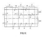
- FIG. 9is a top view of FIG. 8 .
- FIG. 10is a three dimensional view of FIGS. 8 and 9 .
- FIG. 11is a side cross-sectional view of the array according to the second preferred embodiment of the present invention.
- the cross-sectionis perpendicular to the bit lines.
- FIGS. 12-13are schematic side cross-sectional views of angled ion implantation methods to form asymmetric source and drain regions of the second preferred embodiment of the present invention.
- FIG. 14is a schematic side cross-sectional view of a three dimensional array according to the third preferred embodiment of the present invention.
- FIGS. 15-18are schematic side cross-sectional views of formation of interconnects between device levels according to a fourth preferred embodiment of the present invention.
- the present inventorshave realized that memory cell area is enlarged by misalignment tolerances that are put into place to guarantee complete overlap between features on different layers.
- the present inventorshave developed a fully aligned memory cell structure which does not require misalignment tolerances. Therefore, such a cell structure has a smaller area per bit (i.e., per cell) and uses fewer mask steps.
- the fully aligned cell structureincreases memory density and decreases die size and cost. Furthermore, by optionally stacking the cells vertically in the Z-direction, the memory density is further increased, which leads to further decreases in the die size and cost.
- an entire floating gate EEPROM transistormay be made using only two photolithographic masking steps. This decreases the process cost and complexity and ensures the precise alignment or self-alignment of the layers of the transistor, since many of these layers are patterned together using the same photoresist mask.
- channel islandwhich has at least two side surfaces which are aligned to the floating and control gates. Furthermore, forming channel regions as islands and then filling the trenches between the islands with an insulating layer creates trench isolation between adjacent transistors without requiring an extra photolithographic masking step. In contrast, an extra photolithographic masking step is required to form prior art LOCOS or trench isolation between transistors.
- the separate photolithographic masking step to form bit lines of the prior art process of FIG. 1may be eliminated by forming the bit lines using the same masking step used to form the floating gates.
- the floating gate layeris patterned only in one direction to form floating gate rails or strips.
- the semiconductor active region portions exposed between the floating gate railsis implanted and/or silicided to form conductive rails or strips extending parallel to the floating gate rails.
- These conductive rails in the active regionact as the bit lines.
- These bit linesare then covered by an intergate insulating layer which is formed in self-alignment between the floating gate rails.
- the floating gate railsare then patterned to form discrete floating gates using the same mask as is used to form the channel regions and the control gate. Since the intergate insulating layer covers the bit lines during this etching step, the bit lines are not etched during the channel etching step.
- the portions of the bit lines adjacent to the patterned floating gatesact as the source and drain of a given EEPROM transistor
- bit line contact padsi.e., source and drain electrodes
- bit line contact viasare not required because the bit lines may be formed in self-alignment with the EEPROM floating gates.
- the bit and word linesmay have a substantially planar upper surface, which improves the reliability of the device.
- the present inventionis not limited to an array of transistors, and includes the formation of a single transistor. It should also be noted that the array 1 does not have to be formed in a silicon layer located on an insulating surface (i.e., does not have to be formed as a TFT array), and may instead be formed in a bulk silicon substrate to form a bulk MOSFET EEPROM array.
- a substrate having an insulating surfacei.e., a Silicon-On-Insulator (SOI) substrate
- the substratemay comprise a semiconductor (i.e., silicon, GaAs, etc.) wafer covered with an insulating layer, such as a silicon oxide or nitride layer, a glass substrate, a plastic substrate, or a ceramic substrate.
- the substrateis a monocrystalline bulk silicon substrate that has received prior processing steps, such as forming CMOS (complementary metal oxide semiconductor) transistors in the substrate.
- the CMOS transistorsmay comprise peripheral or driver circuitry for the memory array.
- the circuitrycomprises row and column address decoders, column input/outputs (I/O's), and other logic circuitry.
- the driver circuitrymay be formed on an insulating substrate, such as a silicon-on-insulator substrate, a glass substrate, a plastic substrate, or a ceramic substrate.
- the silicon-on-insulator substratemay be formed by any conventional method, such as wafer bonding, Separation by Implantation of Oxygen (SIMOX), and formation of an insulating layer on a silicon substrate.
- SIMOXSeparation by Implantation of Oxygen
- an interlayer insulating layeralso known as an interlayer dielectric
- the interlayer insulating layer 3may comprise one or more of any suitable insulating layers, such as silicon oxide, silicon nitride, silicon oxynitride, PSG, BPSG, BSG, spin-on glass and/or a polymer dielectric layer (such as polyimide, etc.).
- the interlayer insulating layer 3is preferably planarized using chemical-mechanical polishing (CMP), etch back and/or any other means.
- a semiconductor active area layer 5is then deposited over the insulating layer 3 to complete the SOI substrate.
- the semiconductor layerwill be used for the transistor active areas.
- Layer 5may have any desired thickness, such as 10 to 120 nm, preferably less than 100 nm, most preferably less than 30 nm. Layer 5 is chosen so that in depletion regime the space charge region below the transistor gate extends over the entire layer.
- the layer 5may be thinned to the desired thickness using wet silicon etching or by sacrificial oxidation following by a wet oxide etch.
- the semiconductor layer 5comprises an amorphous or polycrystalline silicon layer doped with first conductivity type dopants.
- layer 5may be p-type doped by in-situ doping during deposition, or after deposition by ion implantation or diffusion.
- the crystallinity of the semiconductor layer 5may be improved by heating the layer 5 .
- an amorphous silicon layermay be recrystallized to form polysilicon or a grain size of a polysilicon layer may be increased.
- the heatingmay comprise thermal or laser annealing the layer 5 .
- catalyst induced crystallizationmay be used to improve the crystallinity of layer 5 .
- a catalyst elementsuch as Ni, Ge, Mo, Co, Pt, Pd, a silicide thereof, or other transition metal elements, is placed in contact with the semiconductor layer 5 . Then, the layer 5 is thermally and/or laser annealed.
- the catalyst elementeither propagates through the silicon layer leaving a trail of large grains, or serves as a seed where silicon crystallization begins. In the latter case, the amorphous silicon layer then crystallizes laterally from this seed by means of solid phase crystallization (SPC).
- SPCsolid phase crystallization
- amorphous or polysilicon layer 5may be omitted if a single crystal SOI substrate is used.
- oxygen ionsare implanted deep into a single crystal silicon substrate, forming a buried silicon oxide layer therein. A single crystal silicon layer remains above the buried silicon oxide layer.
- the surface of the active area layer 5is preferably cleaned from impurities and a native oxide is removed.
- a tunnel dielectric 7is formed on the active area layer 5 .
- the tunnel dielectriccomprises a thermally grown silicon oxide layer (i.e., a silicon dioxide layer grown on the silicon layer 5 by exposing layer 5 to an oxygen containing atmosphere to convert a top portion of layer 5 to silicon dioxide).
- the tunnel dielectrichas a thickness of 5 nm to 10 nm, preferably 7 nm. It should be noted that different layer thicknesses and different materials, such as silicon nitride or silicon oxynitride, may be used instead.
- a floating gate layer 9is deposited over, and preferably directly on the tunnel dielectric 7 .
- the floating gate layer 9preferably comprises a polysilicon layer, such as an N+ polysilicon layer.
- a polysilicon layermay have any appropriate thickness, such as 100 to 300 nm, preferably 200 nm, and any appropriate dopant concentration, such as 10 19 -10 21 cm ⁇ 3 , preferably 10 20 cm ⁇ 3 .
- an optional hardmask or etch stop layer 11such as a silicon oxide layer or a dual lower silicon oxide/upper silicon nitride film, is formed on the surface of the floating gate layer 9 .
- Layer 11may have any appropriate thickness, such as, for example 20-200 nm, preferably 50 nm. Materials other than silicon oxide and silicon nitride may be used for layer 11 , if desired.
- a bit line patternis transferred to the in process array using a reverse bit line mask, as shown in FIG. 2 .
- a positive photoresist layer 13is formed over the hardmask layer 11 and then exposed through the reverse bit line mask and developed.
- a negative photoresistis used, then the clear and the opaque areas of the bit line mask are reversed.
- the photoresist mask 13 featuresare etched into the hardmask layer 11 , and the floating gate layer 9 , to form a plurality of rail stacks 15 , as shown in FIG. 2 .
- the tunnel dielectric 7serves as an etch stop layer. Then, the photoresist mask 13 is stripped from the patterned gate rail stacks 15 .
- FIG. 3illustrates the top view of the in process array shown in FIG. 2 .
- the rail stacks 15are in the shape of strips, and contain the floating gate rails 9 and the hardmask rails 11 .
- the tunnel dielectric 7is exposed in the areas between the rail stacks 15 .
- an optional thin layer of silicon nitride, oxynitiride or oxideis grown to seal the exposed sidewalls of the floating gate rails 9 .
- the array bit lines 17are formed by self-aligned ion implantation into the active layer 5 , using the rail stacks 15 as a mask, as shown in FIG. 4 .
- the photoresist layer 13is removed prior to the implantation. Alternatively, it may be left on the rail stacks 15 during this implantation.
- the ion implantationis carried out through the tunnel dielectric 7 . However, if desired, the portions of the tunnel dielectric 7 between the floating gate rails 9 may be removed prior to the ion implantation.
- Channel regions 19 in the active layer 5are located below the floating gate rails 9 .
- the bit lines 17are doped with a second conductivity type dopant different from the first conductivity type dopant of the channels 19 .
- the channels 19are p-type doped, then the bit lines 17 are n-type doped, and vice-versa.
- the spacers 21comprise silicon oxide or silicon nitride. Most preferably, the spacers comprise a different material from the hardmask layer.
- the spacers 21are preferably formed by conformal deposition of a silicon oxide layer over the stacks 15 , followed by an anisotropic oxide etch. The spacer etch process concludes with an etch process for the tunnel dielectric 7 to expose the bit lines 17 . Doping in the bit lines 17 may be increased at this time by additional self-aligned ion implantation, using the rail stacks 15 and spacers 21 as a mask, if desired.
- the implantation before spacer formationis used to form lightly doped portions or extensions of the source/drain (LDD) portions (about 1 ⁇ 10 16 to about 1 ⁇ 10 18 cm ⁇ 3 doping concentration) while the doping after spacer formation is used to form heavily doped source and drain regions (about 1 ⁇ 10 19 to about 1 ⁇ 10 21 cm ⁇ 3 doping concentration).
- the bit linesa n-type doped.
- p-type dopingmay be used instead.
- the formation of the spacers 21 and the lightly doped extensionsmay be omitted if desired.
- the salicide processis then used to form silicide regions 23 in the top of the bit lines 17 in a self-aligned fashion, as shown in FIG. 4 .
- the salicide processcomprises three steps. First a layer of metal, such as Ti, W, Mo, Ta, etc., or a transition metal such as Co, Ni, Pt or Pd is blanket deposited over the exposed bit line regions 17 , the sidewall spacers 21 and the hardmask layer 11 of the rail stacks 15 . The array is annealed to perform a silicidation by direct metallurgical reaction, where the metal layer reacts with the silicon in regions 17 to form the silicide regions 23 over regions 17 .
- metalsuch as Ti, W, Mo, Ta, etc.
- a transition metalsuch as Co, Ni, Pt or Pd
- the unnreacted metal remaining on the spacers 21 and the hardmask layer 11is removed by a selective etch, e.g., by a piranha solution.
- the silicide regions 23comprise portions of the bit lines 17 in addition to the previously doped silicon regions in the active layer 5 .
- FIG. 5shows the top view of the device in FIG. 4 at this stage in the processing.
- the bit lines 17 containing silicide regions 23extend as strips parallel to the rail stacks 15 .
- a conformal intergate insulating layer 25is then deposited to fill the trenches above the bit lines 17 and between the floating gate rails 15 and sidewall spacers, as shown in FIG. 6 (the sidewall spacers 21 are merged into layer 25 in FIG. 6 ).
- the insulating layer 25may comprise any insulating material, such as silicon oxide, silicon oxynitride, phosphosilicate glass (PSG), borophosphosilicate glass (BPSG), borosilicate glass (BSG), spin-on glass, a polymer dielectric layer (such as polyimide, etc.), and/or any other desired insulating material.
- the intergate insulating layeris an isolation silicon oxide layer deposited by a high density plasma (HDP) method.
- HDPhigh density plasma
- the intergate insulating layer 25is formed over and between the rail stacks 15 (i.e., over and adjacent to the floating gate rails 9 ).
- the intergate insulating layer 25is then etched back such that the intergate insulating layer 25 remains adjacent to lower portions 27 of the floating gate rail side surfaces, below top portions 29 of the floating gate rail side surfaces.
- the top portions 29 of the side surfaces of the floating gate rails 9are exposed during this etchback.
- the top portions of the sidewall spacers 21 and the hardmask layer 11are removed from the floating gate rails 9 during the etchback, as shown in FIG. 6 .
- a control gate dielectric layer 31(also known as an inter-poly dielectric) is formed over the floating gate rails 9 , as shown in FIG. 7 .
- the control gate dielectric layer 31is formed on the upper portions 29 of the side surfaces of the floating gate rail 9 and on the top surface of the floating gate rail 9 .
- the control gate dielectric layer 31may have any appropriate thickness, such as 8 to 20 nm, preferably 12 nm of silicon oxide equivalent.
- the control gate dielectricmay comprise several dielectric materials with varying dielectric permittivities.
- the silicon oxide equivalentis silicon oxide of such thickness that when used as a dielectric in a capacitor, it yields the same capacitance per unit area as the control gate dielectric.
- the control gate dielectric layer 31may be grown on the control gate by thermal oxidation or deposited by CVD or other means.
- the control gate dielectricmay comprise silicon oxide, silicon nitride, silicon oxynitride, or a stack comprising a thermally grown silicon oxide layer, a LPCVD deposited silicon nitride layer and a high temperature LPCVD deposited silicon oxide (HTO) layer.
- the top surface and the upper portions 29 of the side surfaces of the floating gate rails 9may be roughened prior to forming the control gate dielectric layer.
- the rougheningmay be accomplished by etching the exposed polysilicon of the rails 9 with an etching medium which selectively attacks polysilicon grain boundaries, such as wet etching with NH 3 OH.
- control gate layer 33is then deposited over the entire device, as shown in FIG. 7 .
- the control gate layer 33is formed on the control gate dielectric layer 31 such that the control gate layer 33 is located over the top surface of the floating gate rails 9 and laterally adjacent to the upper portions 29 of the side surfaces of the floating gate rails. Since the control gate is located adjacent to the top and sides of the floating gate, this increases the capacitance between the floating and control gates.
- the control gate layer 33comprises a multilayer stack comprising a first N+ polysilicon layer, a silicide layer (such as a TiSi or WSi, etc.) and a second N+ polysilicon layer.
- the polysilicon layersare preferably 100-300 nm thick, such as 200 nm thick.
- the silicide layeris preferably 50 to 100 nm thick, such as 60 nm thick.
- the lower polysilicon layerfills in the openings between the floating gates and overlies the control gate dielectric.
- the control gate layercan also be a single layer of silicide, metal, or any other combination of heavily doped amorphous or polycrystalline silicon, silicide, and/or metal.
- a second photoresist mask 35is formed by applying a photoresist layer over the control gate layer 33 , exposing it through the word line mask and developing it.
- the second photoresist mask 35is used as a mask to anisotropically etch the control gate layer 33 , the control gate dielectric layer 31 , the floating gate rails 9 , the tunnel dielectric layer 7 and the active layer 5 to form a plurality of control gates 43 , a plurality of control gate dielectrics 41 , a plurality of floating gates 49 , a plurality of tunnel dielectrics 47 and a plurality of channel island regions 19 , as shown in FIG. 8 .
- Photoresist mask 35is shown in dashed lines to indicate that it has already been removed in the array of FIG. 8 .
- FIG. 8is a cross sectional view along line A-A′ in FIG. 7 .
- Each control gate 43 , control gate dielectric 41 , floating gate 49 , tunnel dielectric 47 and channel island region 19comprise a second rail stack 45 as shown in FIG. 8 .
- the sidewalls of the layers of the rail stacks 45are aligned since the rail stacks 45 were formed during one etching step using the same mask 35 .
- the exposed sidewalls of the channel region islands 19 , the floating gates 49 and the control gates 43 sidewallsmay be optionally sealed by growing a thin layer of silicon nitride or oxide on them, for example by thermal nitridation or oxidation. This completes construction of the memory array 1 .
- An insulating fill layer 50is then deposited between the second rail stacks 45 , and if necessary planarized by chemical mechanical polishing or etchback, over the control gates 43 .
- Layer 50acts as trench isolation fill between the adjacent channel island regions 19 .
- Layer 50preferably comprises the same material as the interlayer insulating layer 3 .
- FIG. 9is a top view and FIG. 10 is a three dimensional view of memory array 1 after the second photoresist mask 35 is removed and layer 50 is formed.
- the array of EEPROMs shown in FIGS. 8-10contains a plurality of bit line columns 17 .
- Each bit line 17contacts the source or the drain regions 57 of the TFT EEPROMs 51 (one exemplary memory cell or TFT EEPROM 51 is delineated by a dotted-dashed line in FIG. 9 ).
- the source and drain regions 57are portions of the bit lines 17 that are located adjacent to the floating gates 49 .
- the bit lines and the source and drain regionsare formed in the same step without requiring an extra photolithographic masking step.
- the columns of bit lines 17extend substantially perpendicular to the source-channel-drain direction of the TFT EEPROMs 51 (i.e., at least a portion of the bit lines extends 0-20 degrees from this perpendicular direction).
- the bit lines 17comprise rails which are located under the intergate insulating layer 25 .
- each region 57is located between two floating gates 49 . Therefore, a particular region 57 may be considered to be a “source” with respect to one adjacent floating gate 49 , and a “drain” with respect to the other adjacent floating gate 49 .
- a source region 57is located adjacent to a first side of the channel island region 19 , while a drain region 57 located adjacent to a second side of the channel island region 19 , such that the channel region is located between the source and drain regions 57 .
- the term “rail” and “rail stack”are not limited to strips which extend in only one direction, and the “rails” and “rail stacks” may have curves or bends and extend in more than one direction.
- the array 1also contains a plurality of word lines 53 which contain the control gates 43 .
- the control gate 43 of each transistorcomprises a portion of a word line 53 .
- the rows of word lines 53extend substantially parallel to the source-channel-drain direction of the TFT EEPROMs 51 (i.e., at least a portion of the word lines extends 0-20 degrees from this parallel direction).
- the floating gates 49comprise posts located between the channel islands 19 and the control gates 43 .
- the posts 49have four side surfaces as shown in FIGS. 6 , 7 , 8 and 9 .
- the first 55 and second 56 side surfaces of the control gate 43are aligned to third 59 and fourth 61 side surfaces of the channel island region 19 , and to third 63 and the fourth 65 side surfaces of the floating gate 49 , as shown in FIG. 8 .
- the first 55 and the second 56 side surfaces of the control gate 43are aligned to side surfaces of the control gate dielectric 41 and to side surfaces of the tunneling dielectric 47 , as shown in FIG. 8 .
- the word line photolithography stepdoes not require misalignment tolerances, since the word lines 53 are patterned using the same mask as the floating gate rails 9 and the active layer 5 (i.e., channel regions 19 ) of each TFT 51 in the cell. Therefore, the word lines 53 are not only aligned to the floating gates 49 of the TFT EEPROMs 51 but are also aligned to the channel regions 19 of each memory cell. Furthermore, during the same etching step, the adjacent control gates, floating gates and channel islands are isolated from each other. By using a fully aligned memory cell, the number of expensive and time consuming photolithography steps are reduced. Furthermore, since no misalignment tolerances for each cell are required, the cell density is increased. Another advantage of the device of the first embodiment is that since a thick intergate insulating layer 25 is located between the bit lines 17 and the word lines 53 , the parasitic capacitance and a chance of a short circuit between the bit lines and the word lines are decreased.
- the nonvolatile memory array 1may be programmed and erased by various conventional mechanisms.
- the cells or TFT EEPROMs 51 of the arraymay be programmed or written by applying a programming voltage between the source and drain regions to achieve channel hot carrier (e.g., electron) injection into the floating gate 49 .
- the cells or TFTs 51 of the arraymay be erased in blocks by applying an erase voltage between the control gate and a source or a drain to achieve Fowler-Nordheim carrier (i.e., electron) tunneling from the floating gate to the channel.
- Fowler-Nordheim carrieri.e., electron
- the array 100contains cells or TFTs 151 which have asymmetric source and drain regions 157 , as shown in FIG. 11 .
- the drain overlap with the floating gate 149is much larger than the source overlap with the floating gate 149 .
- a region 157 that acts as a source for one floating gate 149acts as a drain for an adjacent floating gate 149 .
- the other features of the TFTs 151are the same as those of TFTs 51 described in the first preferred embodiment.
- the array 100may be programmed or written bitwise by Fowler-Nordheim tunneling from the floating gate 149 to the drain 157 .
- the control gate 143is grounded, while a programming voltage is applied to the asymmetric drain regions 157 , while the source regions 157 float. Since the source region is offset from the floating gate, no tunneling occurs from the floating gate to the source. This programming step decreases the threshold voltage of the TFT 151 .
- the cells or TFTs 151 of the array 100may be erased in blocks by applying a high erase voltage to the control gate and grounding the source and drain regions to achieve Fowler-Nordheim carrier (i.e., electron) tunneling from the channel to the floating gate. This programming increases the threshold voltage of the TFT 151 .
- the asymmetric source and drain regions 157may be formed by any desired method.
- the source and drain regions 157are formed by performing an angled ion implant 161 using the first rail stack 115 as a mask.
- the angled implant 161comprises implanting heavily doped source and drain regions 157 . If desired to form lightly doped portions of the source regions 163 , then a lightly doped source region 163 is implanted at a smaller angle 165 sufficient to achieve an offset source as shown in FIG. 13 .
- the first and second preferred embodimentsdescribe and illustrate a cross-point array of word lines and bit lines at a horizontal level and a method of making thereof.
- Each memory cellconsists of a single programmable field effect transistor (i.e., TFT), with its source and drain connected to the j th bit line and the (j+1) st bit line, respectively, and a control gate being either connected to or comprising the k th word line.
- This memory arrangementis known as the NOR Virtual Ground (NVG) Array (also referred to as VGA).
- VGANOR Virtual Ground
- the memory arraymay also be arranged in non volatile flash memory architectures other than VGA, such as NOR-type memory or Dual String NOR (DuSNOR) memory, for example.
- the DuSNOR architecturewhere two adjacent cell strings share a common source line but use different drain lines, is described in K. S. Kim, et al., IEDM-95, (1995) page 263, incorporated herein by reference.
- the DuSNOR memorymay be fabricated using the same process as the VGA memory, except that an additional masking step is used to pattern the active area layer 5 to separate the drain regions of adjacent cells.
- the active area 5is patterned using a third mask to form a plurality of islands containing two EEPROM transistors sharing a common source.
- this additional masking stepcan instead be used to separate both drains and sources of adjacent cells, thus achieving full isolation of adjacent cell strings.
- the active area 5is patterned using a third mask to form a plurality of islands containing one EEPROM transistor to form an array with separated drain and source lines. Thus, each cell does not share a source or a drain (i.e., bit) line with a laterally adjacent cell.
- This NOR-type memory array architectureis known as Separated Source Line NOR (SSL-NOR) memory.
- the SSL-NOR array architectureis described in I. Fujiwara, et al., Proceedings of Non-Volatile Semiconductor Memory Workshop (2000), page 117, incorporated herein by reference.
- the process sequence of the first and second preferred embodiments of the present inventionrequires only two photolithographic masking steps to form each cell.
- One masking stepis for gate patterning/self aligned bit line formation.
- the other masking stepis for word line patterning.
- the methods of the preferred embodiments of the present inventionexploit self-alignment to reduce alignment tolerances between the masks.
- the memory cell area achieved with the foregoing processis about 4f 2 , where f is the minimum feature size (i.e. 0.18 microns in a 0.18 micron semiconductor process).
- the term “about”allows for small deviations (10% or less) due to non-uniform process conditions and other small deviations from desired process parameters.
- the array of the first and second preferred embodimentsis very suitable for vertical stacking of horizontal planar arrays to form a three dimensional array of device levels, each device level containing an array TFT EEPROMs described above.
- FIG. 14illustrates a three dimensional memory array 200 of the third preferred embodiment containing a plurality of device levels 202 , the device levels containing the array 1 or 100 of TFT EEPROMs described above.
- Each device level 202 of the array 200is separated and decoupled in the vertical direction by an interlayer insulating layer 203 .
- the interlayer insulating layer 203also isolates adjacent word lines 53 and adjacent portions of the active areas 5 below the respective word lines in each device level 202 . Connection between the bit lines, word lines and peripheral or driver circuits in the substrate 206 is made through vertical interlevel interconnects 208 .
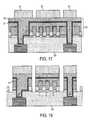
- FIGS. 15 through 18illustrate a method of forming vertical interlevel interconnects 208 between an upper device level 202 and a lower device level 202 or driver circuits in the substrate 206 , according to a fourth preferred embodiment of the present invention.
- a photoresist mask 209is formed by applying a photoresist layer over the first N+ polysilicon layer of the control gate layer 33 , exposing the photoresist layer through an interlevel interconnect mask and developing the photoresist, as shown in FIG. 15 .
- the photoresist mask 209is used to anisotropically etch the first N+ polysilicon layer 33 , the control gate dielectric layer 31 , the floating gate rails 9 , the tunnel dielectric layer 7 , and the active layer 5 , stopping the etch on the interlayer insulating layer 203 and the intergate insulating layer 25 . Then, the insulating layers 203 and 25 are etched anisotropically using mask 209 to form at least one via extending to the lower device level 202 or substrate 206 , as shown in FIG. 16 . The use of the intergate insulating layer 25 as an etch stop allows the formation of a stepped via, as shown on the left side of FIG. 16 . The photoresist mask 209 is subsequently removed.
- a conducting layer 211comprising a metal layer, such as Ti, W, etc., or a silicide layer, such as TiSi, WSi, etc., is deposited conformally on the first heavily doped N+ polysilicon layer 33 , followed by conformal deposition of an optional second N+ polysilicon layer 213 .
- P+ polysiliconmay be used instead of N+ polysilicon for these layers.
- the wordline photoresist mask 35is formed over layer 213 , as shown in FIG. 17 .
- the control gate etch processis performed similar to that shown in FIG.
- the vertical interlevel interconnects 208are formed, as shown in FIG. 18 .
- the patterned conducting layer 211 and the second polysilicon layer 213form the interconnects 208 as well as the upper portion of the control gates 43 (i.e., an upper portion of the word lines or gate lines 53 ).
- the word or gate linecomprises the same layer(s) as the interlevel interconnects.
- the array of nonvolatile memory devices 200comprises a monolithic three dimensional array of memory devices.
- the term “monolithic”means that layers of each level of the array 200 were directly deposited on the layers of each underlying level of the array.
- a first array or device level 202 of TFT EEPROMsis provided over the substrate 206 .
- the interlayer insulating layer 203is formed over this array. Then, at least one or more additional arrays or device levels 202 of TFT EEPROMs are monolithically formed on the interlayer insulating layer 203 .
- two dimensional arraysmay be formed separately and then packaged together to form a non-monolithic three dimensional memory array 200 .
- a plurality of arrays 1 or 100 of TFT EEPROMsare formed on different silicon-on-insulator substrates. The substrates are thinned by polishing or etching the back sides of the substrates. The arrays are then attached or glued to each other to form a three dimensional memory array 200 .
- the TFTs in a plurality of the levels 202 of the three dimensional array 200 of FIG. 14undergo a recrystallization and/or a dopant activation step at the same time. This reduces the device fabrication time and cost. Furthermore, if each level of the array is subjected to a separate crystallization and/or dopant activation annealing. then the lower levels would undergo more annealing steps than the upper levels. This may lead to device non uniformity because the grain size may be larger in the active areas of the lower levels and/or the source and drain regions may have a different dopant distribution in the lower levels than in the upper levels.
- Each cell in one level 202 of the memory array 200can be formed using only two photolithographic masking steps. However, additional masking steps may be needed to form contacts to the bit lines and the word lines.
- the preferred aspects of the present inventionmay also be applied to nonvolatile flash memory architectures other than VGA, DuSNOR and SSL-NOR memory.
- the present inventionis not limited to TFT EEPROM flash memory arrays, and also encompasses other semiconductor devices within its scope.
- the self-aligned transistorsmay be MOSFETs in a bulk substrate.
- These self-aligned transistorsmay be used as non-flash EEPROMs (i.e., EEPROMs where each transistor is erased separately), UV erasable PROMs (EPROMs), mask ROMs, dynamic random access memories (DRAMs), liquid crystal displays (LCDs), field programmable gate arrays (FPGA) and microprocessors.
- non-flash EEPROMsi.e., EEPROMs where each transistor is erased separately
- EPROMsUV erasable PROMs
- DRAMsdynamic random access memories
- LCDsliquid crystal displays
- FPGAfield programmable gate arrays
Landscapes
- Non-Volatile Memory (AREA)
- Semiconductor Memories (AREA)
Abstract
Description
Claims (17)
Priority Applications (2)
| Application Number | Priority Date | Filing Date | Title |
|---|---|---|---|
| US10/066,376US6897514B2 (en) | 2001-03-28 | 2002-02-05 | Two mask floating gate EEPROM and method of making |
| US10/849,152US7615436B2 (en) | 2001-03-28 | 2004-05-20 | Two mask floating gate EEPROM and method of making |
Applications Claiming Priority (3)
| Application Number | Priority Date | Filing Date | Title |
|---|---|---|---|
| US27985501P | 2001-03-28 | 2001-03-28 | |
| US09/927,648US6881994B2 (en) | 2000-08-14 | 2001-08-13 | Monolithic three dimensional array of charge storage devices containing a planarized surface |
| US10/066,376US6897514B2 (en) | 2001-03-28 | 2002-02-05 | Two mask floating gate EEPROM and method of making |
Related Parent Applications (1)
| Application Number | Title | Priority Date | Filing Date |
|---|---|---|---|
| US09/927,648Continuation-In-PartUS6881994B2 (en) | 2000-08-14 | 2001-08-13 | Monolithic three dimensional array of charge storage devices containing a planarized surface |
Related Child Applications (1)
| Application Number | Title | Priority Date | Filing Date |
|---|---|---|---|
| US10/849,152DivisionUS7615436B2 (en) | 2001-03-28 | 2004-05-20 | Two mask floating gate EEPROM and method of making |
Publications (2)
| Publication Number | Publication Date |
|---|---|
| US20020142546A1 US20020142546A1 (en) | 2002-10-03 |
| US6897514B2true US6897514B2 (en) | 2005-05-24 |
Family
ID=26959918
Family Applications (2)
| Application Number | Title | Priority Date | Filing Date |
|---|---|---|---|
| US10/066,376Expired - Fee RelatedUS6897514B2 (en) | 2001-03-28 | 2002-02-05 | Two mask floating gate EEPROM and method of making |
| US10/849,152Expired - LifetimeUS7615436B2 (en) | 2001-03-28 | 2004-05-20 | Two mask floating gate EEPROM and method of making |
Family Applications After (1)
| Application Number | Title | Priority Date | Filing Date |
|---|---|---|---|
| US10/849,152Expired - LifetimeUS7615436B2 (en) | 2001-03-28 | 2004-05-20 | Two mask floating gate EEPROM and method of making |
Country Status (1)
| Country | Link |
|---|---|
| US (2) | US6897514B2 (en) |
Cited By (29)
| Publication number | Priority date | Publication date | Assignee | Title |
|---|---|---|---|---|
| US20040126949A1 (en)* | 2002-08-19 | 2004-07-01 | Samsung Electronics Co., Ltd. | Gate electrode of a semiconductor device and method of forming the same |
| US20050112804A1 (en)* | 2002-03-13 | 2005-05-26 | Matrix Semiconductor, Inc. | Silicide-silicon oxide-semiconductor antifuse device and method of making |
| US20050201150A1 (en)* | 2003-06-06 | 2005-09-15 | Chih-Hsin Wang | Method and apparatus for semiconductor device and semiconductor memory device |
| US20060001053A1 (en)* | 2003-06-06 | 2006-01-05 | Chih-Hsin Wang | Method and apparatus transporting charges in semiconductor device and semiconductor memory device |
| US20060006454A1 (en)* | 2004-07-01 | 2006-01-12 | Chih-Hsin Wang | Electrically alterable memory cell |
| US20060014329A1 (en)* | 2004-07-16 | 2006-01-19 | Samsung Electronics Co., Ltd., | Nanodots formed on silicon oxide and method of manufacturing the same |
| US20060145272A1 (en)* | 2004-12-30 | 2006-07-06 | Kim Heung J | Mask ROM and fabricating method thereof |
| US20060205132A1 (en)* | 2004-11-23 | 2006-09-14 | Micron Technology, Inc. | Scalable integrated logic and non-volatile memory |
| US20060208305A1 (en)* | 2004-07-19 | 2006-09-21 | Micron Technology, Inc. | In-service reconfigurable DRAM and flash memory device |
| US20060244037A1 (en)* | 2005-01-24 | 2006-11-02 | Hiroaki Kouketsu | Semiconductor device and fabrication method thereof |
| US20060289924A1 (en)* | 2005-06-28 | 2006-12-28 | Chih-Hsin Wang | Low power electrically alterable nonvolatile memory cells and arrays |
| US20070008778A1 (en)* | 2003-06-06 | 2007-01-11 | Chih-Hsin Wang | Methods for operating semiconductor device and semiconductor memory device |
| US20070134876A1 (en)* | 2005-12-09 | 2007-06-14 | Macronix International Co., Ltd. | Stacked thin film transistor, non-volatile memory devices and methods for fabricating the same |
| US20070161150A1 (en)* | 2005-12-28 | 2007-07-12 | Intel Corporation | Forming ultra dense 3-D interconnect structures |
| US20070273234A1 (en)* | 2006-05-23 | 2007-11-29 | Melfi Michael J | Cogging reduction in permanent magnet machines |
| US20080026530A1 (en)* | 2006-07-26 | 2008-01-31 | Tobias Mono | Method of forming a doped portion of a semiconductor and method of forming a transistor |
| US20080203464A1 (en)* | 2004-07-01 | 2008-08-28 | Chih-Hsin Wang | Electrically alterable non-volatile memory and array |
| US20090046515A1 (en)* | 2007-08-14 | 2009-02-19 | Sung Kun Park | NOR Flash Memory Device and Method for Fabricating the Same |
| CN100501978C (en)* | 2005-12-09 | 2009-06-17 | 旺宏电子股份有限公司 | Stacked thin film transistor nonvolatile memory device and method of manufacturing the same |
| US20090180324A1 (en)* | 2008-01-15 | 2009-07-16 | Ramaswamy D V Nirmal | Semiconductor Constructions, NAND Unit Cells, Methods Of Forming Semiconductor Constructions, And Methods Of Forming NAND Unit Cells |
| US20090294842A1 (en)* | 2008-05-30 | 2009-12-03 | Micron Technology, Inc. | Methods of forming data cells and connections to data cells |
| US20100224923A1 (en)* | 2009-03-04 | 2010-09-09 | Yong-Hoon Son | Semiconductor memory device and method of manufacturing the same |
| US20100252874A1 (en)* | 2009-04-06 | 2010-10-07 | Thomas Schulz | Memory Device |
| US8072023B1 (en) | 2007-11-12 | 2011-12-06 | Marvell International Ltd. | Isolation for non-volatile memory cell array |
| US8120088B1 (en) | 2007-12-07 | 2012-02-21 | Marvell International Ltd. | Non-volatile memory cell and array |
| US20150214332A1 (en)* | 2012-09-12 | 2015-07-30 | Institute of Microelectronics, Chinese Academy of Sciences | Method for manufacturing semiconductor device |
| US9240405B2 (en) | 2011-04-19 | 2016-01-19 | Macronix International Co., Ltd. | Memory with off-chip controller |
| USRE47311E1 (en) | 2005-01-03 | 2019-03-19 | Macronix International Co., Ltd. | Silicon on insulator and thin film transistor bandgap engineered split gate memory |
| US12419037B2 (en) | 2022-01-07 | 2025-09-16 | Changxin Memory Technologies, Inc. | Semiconductor structure and method for manufacturing semiconductor structure |
Families Citing this family (51)
| Publication number | Priority date | Publication date | Assignee | Title |
|---|---|---|---|---|
| KR100821456B1 (en) | 2000-08-14 | 2008-04-11 | 샌디스크 쓰리디 엘엘씨 | Dense array and charge storage device and manufacturing method thereof |
| US7125763B1 (en)* | 2000-09-29 | 2006-10-24 | Spansion Llc | Silicided buried bitline process for a non-volatile memory cell |
| US6841813B2 (en) | 2001-08-13 | 2005-01-11 | Matrix Semiconductor, Inc. | TFT mask ROM and method for making same |
| US6744094B2 (en)* | 2001-08-24 | 2004-06-01 | Micron Technology Inc. | Floating gate transistor with horizontal gate layers stacked next to vertical body |
| US6706576B1 (en)* | 2002-03-14 | 2004-03-16 | Advanced Micro Devices, Inc. | Laser thermal annealing of silicon nitride for increased density and etch selectivity |
| US6737675B2 (en) | 2002-06-27 | 2004-05-18 | Matrix Semiconductor, Inc. | High density 3D rail stack arrays |
| US6807119B2 (en)* | 2002-12-23 | 2004-10-19 | Matrix Semiconductor, Inc. | Array containing charge storage and dummy transistors and method of operating the array |
| US6849905B2 (en)* | 2002-12-23 | 2005-02-01 | Matrix Semiconductor, Inc. | Semiconductor device with localized charge storage dielectric and method of making same |
| US6885044B2 (en)* | 2003-07-30 | 2005-04-26 | Promos Technologies, Inc. | Arrays of nonvolatile memory cells wherein each cell has two conductive floating gates |
| KR100685880B1 (en)* | 2004-12-30 | 2007-02-23 | 동부일렉트로닉스 주식회사 | Flash Y pyrom cell and manufacturing method thereof |
| US7776686B2 (en)* | 2005-03-08 | 2010-08-17 | Nec Electronics Corporation | Method of fabricating a non-volatile memory element including nitriding and oxidation of an insulating film |
| US8174017B2 (en)* | 2005-08-17 | 2012-05-08 | Georgia Tech Research Corporation | Integrating three-dimensional high capacitance density structures |
| US7538384B2 (en)* | 2005-12-05 | 2009-05-26 | Taiwan Semiconductor Manufacturing Company, Ltd. | Non-volatile memory array structure |
| US7394128B2 (en)* | 2005-12-15 | 2008-07-01 | Infineon Technologies Ag | Semiconductor memory device with channel regions along sidewalls of fins |
| DE102005060083B4 (en)* | 2005-12-15 | 2014-08-28 | Qimonda Ag | Semiconductor memory device, method for its formation, memory cell and method for their training |
| US7439594B2 (en) | 2006-03-16 | 2008-10-21 | Micron Technology, Inc. | Stacked non-volatile memory with silicon carbide-based amorphous silicon thin film transistors |
| JP4594921B2 (en)* | 2006-12-18 | 2010-12-08 | 株式会社東芝 | Method for manufacturing nonvolatile semiconductor device |
| KR20080060486A (en)* | 2006-12-27 | 2008-07-02 | 동부일렉트로닉스 주식회사 | Flash memory and manufacturing method thereof |
| JP2008166437A (en)* | 2006-12-27 | 2008-07-17 | Spansion Llc | Semiconductor device, control method thereof, and manufacturing method thereof |
| US7718546B2 (en)* | 2007-06-27 | 2010-05-18 | Sandisk 3D Llc | Method for fabricating a 3-D integrated circuit using a hard mask of silicon-oxynitride on amorphous carbon |
| US20090050471A1 (en)* | 2007-08-24 | 2009-02-26 | Spansion Llc | Process of forming an electronic device including depositing layers within openings |
| US8008216B2 (en)* | 2007-09-24 | 2011-08-30 | Texas Instruments Incorporated | Nitrogen profile in high-K dielectrics using ultrathin disposable capping layers |
| US8999823B2 (en)* | 2008-10-23 | 2015-04-07 | Sharp Kabushiki Kaisha | Semiconductor device, method for manufacturing same, and display device |
| US8097911B2 (en)* | 2008-12-31 | 2012-01-17 | Intel Corporation | Etch stop structures for floating gate devices |
| US8507966B2 (en) | 2010-03-02 | 2013-08-13 | Micron Technology, Inc. | Semiconductor cells, arrays, devices and systems having a buried conductive line and methods for forming the same |
| US9646869B2 (en)* | 2010-03-02 | 2017-05-09 | Micron Technology, Inc. | Semiconductor devices including a diode structure over a conductive strap and methods of forming such semiconductor devices |
| US8288795B2 (en) | 2010-03-02 | 2012-10-16 | Micron Technology, Inc. | Thyristor based memory cells, devices and systems including the same and methods for forming the same |
| US9608119B2 (en) | 2010-03-02 | 2017-03-28 | Micron Technology, Inc. | Semiconductor-metal-on-insulator structures, methods of forming such structures, and semiconductor devices including such structures |
| US8513722B2 (en) | 2010-03-02 | 2013-08-20 | Micron Technology, Inc. | Floating body cell structures, devices including same, and methods for forming same |
| US8877596B2 (en) | 2010-06-24 | 2014-11-04 | International Business Machines Corporation | Semiconductor devices with asymmetric halo implantation and method of manufacture |
| US8598621B2 (en) | 2011-02-11 | 2013-12-03 | Micron Technology, Inc. | Memory cells, memory arrays, methods of forming memory cells, and methods of forming a shared doped semiconductor region of a vertically oriented thyristor and a vertically oriented access transistor |
| US8952418B2 (en) | 2011-03-01 | 2015-02-10 | Micron Technology, Inc. | Gated bipolar junction transistors |
| EP2495762B1 (en)* | 2011-03-03 | 2017-11-01 | IMEC vzw | Method for producing a floating gate semiconductor memory device |
| US8519431B2 (en) | 2011-03-08 | 2013-08-27 | Micron Technology, Inc. | Thyristors |
| US8900988B2 (en) | 2011-04-15 | 2014-12-02 | International Business Machines Corporation | Method for forming self-aligned airgap interconnect structures |
| US9054160B2 (en) | 2011-04-15 | 2015-06-09 | International Business Machines Corporation | Interconnect structure and method for fabricating on-chip interconnect structures by image reversal |
| US8890318B2 (en) | 2011-04-15 | 2014-11-18 | International Business Machines Corporation | Middle of line structures |
| US9318614B2 (en)* | 2012-08-02 | 2016-04-19 | Cbrite Inc. | Self-aligned metal oxide TFT with reduced number of masks and with reduced power consumption |
| US8796754B2 (en)* | 2011-06-22 | 2014-08-05 | Macronix International Co., Ltd. | Multi level programmable memory structure with multiple charge storage structures and fabricating method thereof |
| US8772848B2 (en) | 2011-07-26 | 2014-07-08 | Micron Technology, Inc. | Circuit structures, memory circuitry, and methods |
| US8822137B2 (en) | 2011-08-03 | 2014-09-02 | International Business Machines Corporation | Self-aligned fine pitch permanent on-chip interconnect structures and method of fabrication |
| US20130062732A1 (en)* | 2011-09-08 | 2013-03-14 | International Business Machines Corporation | Interconnect structures with functional components and methods for fabrication |
| US9087753B2 (en) | 2012-05-10 | 2015-07-21 | International Business Machines Corporation | Printed transistor and fabrication method |
| US9305941B2 (en)* | 2012-11-02 | 2016-04-05 | Apple Inc. | Device and method for improving AMOLED driving |
| US9478495B1 (en) | 2015-10-26 | 2016-10-25 | Sandisk Technologies Llc | Three dimensional memory device containing aluminum source contact via structure and method of making thereof |
| CN108878431A (en)* | 2017-05-11 | 2018-11-23 | 北京兆易创新科技股份有限公司 | A kind of NOR type floating-gate memory and preparation method |
| CN108878434A (en)* | 2017-05-11 | 2018-11-23 | 北京兆易创新科技股份有限公司 | A kind of NOR type floating-gate memory and preparation method |
| CN108878430A (en)* | 2017-05-11 | 2018-11-23 | 北京兆易创新科技股份有限公司 | A kind of NOR type floating-gate memory and preparation method |
| CN110476209B (en) | 2019-06-28 | 2020-11-17 | 长江存储科技有限责任公司 | In-memory computation in three-dimensional memory devices |
| WO2020258209A1 (en)* | 2019-06-28 | 2020-12-30 | Yangtze Memory Technologies Co., Ltd. | Computation-in-memory in three-dimensional memory device |
| CN115581069A (en)* | 2021-06-21 | 2023-01-06 | 联华电子股份有限公司 | Electronic erasable rewritable read-only memory array and its forming method |
Citations (149)
| Publication number | Priority date | Publication date | Assignee | Title |
|---|---|---|---|---|
| US3414892A (en) | 1967-12-26 | 1968-12-03 | Lab For Electronics Inc | Means interconnecting printed circuit memory planes |
| US3432827A (en) | 1964-09-04 | 1969-03-11 | An Controls Inc Di | Stacked magnetic memory system |
| US3571809A (en) | 1968-11-04 | 1971-03-23 | Energy Conversion Devices Inc | Memory matrix having serially connected threshold and memory switch devices at each cross-over point |
| US3573757A (en) | 1968-11-04 | 1971-04-06 | Energy Conversion Devices Inc | Memory matrix having serially connected threshold and memory switch devices at each cross-over point |
| US3576549A (en) | 1969-04-14 | 1971-04-27 | Cogar Corp | Semiconductor device, method, and memory array |
| US3582908A (en) | 1969-03-10 | 1971-06-01 | Bell Telephone Labor Inc | Writing a read-only memory while protecting nonselected elements |
| US3629863A (en) | 1968-11-04 | 1971-12-21 | Energy Conversion Devices Inc | Film deposited circuits and devices therefor |
| US3634929A (en) | 1968-11-02 | 1972-01-18 | Tokyo Shibaura Electric Co | Method of manufacturing semiconductor integrated circuits |
| US3671948A (en) | 1970-09-25 | 1972-06-20 | North American Rockwell | Read-only memory |
| US3699543A (en) | 1968-11-04 | 1972-10-17 | Energy Conversion Devices Inc | Combination film deposited switch unit and integrated circuits |
| US3717852A (en) | 1971-09-17 | 1973-02-20 | Ibm | Electronically rewritable read-only memory using via connections |
| US3728695A (en) | 1971-10-06 | 1973-04-17 | Intel Corp | Random-access floating gate mos memory array |
| US3787822A (en) | 1971-04-23 | 1974-01-22 | Philips Corp | Method of providing internal connections in a semiconductor device |
| US3846767A (en) | 1973-10-24 | 1974-11-05 | Energy Conversion Devices Inc | Method and means for resetting filament-forming memory semiconductor device |
| US3863231A (en) | 1973-07-23 | 1975-01-28 | Nat Res Dev | Read only memory with annular fuse links |
| US3877049A (en) | 1973-11-28 | 1975-04-08 | William D Buckley | Electrodes for amorphous semiconductor switch devices and method of making the same |
| US3886577A (en) | 1973-09-12 | 1975-05-27 | Energy Conversion Devices Inc | Filament-type memory semiconductor device and method of making the same |
| US3922648A (en) | 1974-08-19 | 1975-11-25 | Energy Conversion Devices Inc | Method and means for preventing degradation of threshold voltage of filament-forming memory semiconductor device |
| US3980505A (en) | 1973-09-12 | 1976-09-14 | Buckley William D | Process of making a filament-type memory semiconductor device |
| US3990098A (en) | 1972-12-22 | 1976-11-02 | E. I. Du Pont De Nemours And Co. | Structure capable of forming a diode and associated conductive path |
| US4146902A (en) | 1975-12-03 | 1979-03-27 | Nippon Telegraph And Telephone Public Corp. | Irreversible semiconductor switching element and semiconductor memory device utilizing the same |
| US4177475A (en) | 1977-10-31 | 1979-12-04 | Burroughs Corporation | High temperature amorphous memory device for an electrically alterable read-only memory |
| US4203123A (en) | 1977-12-12 | 1980-05-13 | Burroughs Corporation | Thin film memory device employing amorphous semiconductor materials |
| US4203158A (en) | 1978-02-24 | 1980-05-13 | Intel Corporation | Electrically programmable and erasable MOS floating gate memory device employing tunneling and method of fabricating same |
| US4272880A (en) | 1979-04-20 | 1981-06-16 | Intel Corporation | MOS/SOS Process |
| US4281397A (en) | 1979-10-29 | 1981-07-28 | Texas Instruments Incorporated | Virtual ground MOS EPROM or ROM matrix |
| EP0073486A2 (en) | 1981-08-31 | 1983-03-09 | Kabushiki Kaisha Toshiba | Stacked semiconductor memory |
| US4419741A (en) | 1980-01-28 | 1983-12-06 | Rca Corporation | Read only memory (ROM) having high density memory array with on pitch decoder circuitry |
| US4420766A (en) | 1981-02-09 | 1983-12-13 | Harris Corporation | Reversibly programmable polycrystalline silicon memory element |
| US4442507A (en) | 1981-02-23 | 1984-04-10 | Burroughs Corporation | Electrically programmable read-only memory stacked above a semiconductor substrate |
| US4489478A (en) | 1981-09-29 | 1984-12-25 | Fujitsu Limited | Process for producing a three-dimensional semiconductor device |
| US4494135A (en) | 1976-04-06 | 1985-01-15 | U.S. Philips Corporation | Programmable read only memory cell having an electrically destructible programmation element integrally formed with a junction diode |
| US4498226A (en) | 1981-08-31 | 1985-02-12 | Tokyo Shibaura Denki Kabushiki Kaisha | Method for manufacturing three-dimensional semiconductor device by sequential beam epitaxy |
| US4499557A (en) | 1980-10-28 | 1985-02-12 | Energy Conversion Devices, Inc. | Programmable cell for use in programmable electronic arrays |
| US4500905A (en) | 1981-09-30 | 1985-02-19 | Tokyo Shibaura Denki Kabushiki Kaisha | Stacked semiconductor device with sloping sides |
| US4507757A (en) | 1982-03-23 | 1985-03-26 | Texas Instruments Incorporated | Avalanche fuse element in programmable memory |
| US4535424A (en) | 1982-06-03 | 1985-08-13 | Texas Instruments Incorporated | Solid state three dimensional semiconductor memory array |
| US4543594A (en) | 1982-09-07 | 1985-09-24 | Intel Corporation | Fusible link employing capacitor structure |
| US4569121A (en) | 1983-03-07 | 1986-02-11 | Signetics Corporation | Method of fabricating a programmable read-only memory cell incorporating an antifuse utilizing deposition of amorphous semiconductor layer |
| JPS61222216A (en) | 1985-03-28 | 1986-10-02 | Canon Inc | Manufacture of superlattice semiconductor device |
| US4630096A (en) | 1984-05-30 | 1986-12-16 | Motorola, Inc. | High density IC module assembly |
| US4646266A (en) | 1984-09-28 | 1987-02-24 | Energy Conversion Devices, Inc. | Programmable semiconductor structures and methods for using the same |
| US4672577A (en) | 1984-06-18 | 1987-06-09 | Hiroshima University | Three-dimensional integrated circuit with optically coupled shared memories |
| US4677742A (en) | 1983-01-18 | 1987-07-07 | Energy Conversion Devices, Inc. | Electronic matrix arrays and method for making the same |
| US4710798A (en) | 1985-09-10 | 1987-12-01 | Northern Telecom Limited | Integrated circuit chip package |
| US4729005A (en) | 1985-04-29 | 1988-03-01 | General Electric Company | Method and apparatus for improved metal-insulator-semiconductor device operation |
| JPS6352463B2 (en) | 1978-11-08 | 1988-10-19 | Kyushu Nippon Electric | |
| US4811082A (en) | 1986-11-12 | 1989-03-07 | International Business Machines Corporation | High performance integrated circuit packaging structure |
| US4811114A (en) | 1986-02-24 | 1989-03-07 | Konishiroku Photo Industry Co., Ltd. | Image reading apparatus |
| US4820657A (en) | 1987-02-06 | 1989-04-11 | Georgia Tech Research Corporation | Method for altering characteristics of junction semiconductor devices |
| US4823181A (en) | 1986-05-09 | 1989-04-18 | Actel Corporation | Programmable low impedance anti-fuse element |
| US4876220A (en) | 1986-05-16 | 1989-10-24 | Actel Corporation | Method of making programmable low impedance interconnect diode element |
| US4881114A (en) | 1986-05-16 | 1989-11-14 | Actel Corporation | Selectively formable vertical diode circuit element |
| US4899205A (en) | 1986-05-09 | 1990-02-06 | Actel Corporation | Electrically-programmable low-impedance anti-fuse element |
| US4922319A (en) | 1985-09-09 | 1990-05-01 | Fujitsu Limited | Semiconductor programmable memory device |
| US4943538A (en) | 1986-05-09 | 1990-07-24 | Actel Corporation | Programmable low impedance anti-fuse element |
| EP0387834A2 (en) | 1989-03-14 | 1990-09-19 | Kabushiki Kaisha Toshiba | Semiconductor structure for processing and storing of information |
| EP0395886A2 (en) | 1989-04-03 | 1990-11-07 | Olympus Optical Co., Ltd. | Memory cell and multidimensinal memory device constituted by arranging the memory cells |
| US5001539A (en) | 1988-07-08 | 1991-03-19 | Mitsubishi Denki Kabushiki Kaisha | Multiple layer static random access memory device |
| US5070383A (en) | 1989-01-10 | 1991-12-03 | Zoran Corporation | Programmable memory matrix employing voltage-variable resistors |
| US5070384A (en) | 1990-04-12 | 1991-12-03 | Actel Corporation | Electrically programmable antifuse element incorporating a dielectric and amorphous silicon interlayer |
| US5089862A (en) | 1986-05-12 | 1992-02-18 | Warner Jr Raymond M | Monocrystalline three-dimensional integrated circuit |
| US5091762A (en) | 1988-07-05 | 1992-02-25 | Kabushiki Kaisha Toshiba | Semiconductor memory device with a 3-dimensional structure |
| US5160987A (en) | 1989-10-26 | 1992-11-03 | International Business Machines Corporation | Three-dimensional semiconductor structures formed from planar layers |
| EP0516866A1 (en) | 1991-05-03 | 1992-12-09 | International Business Machines Corporation | Modular multilayer interwiring structure |
| US5191405A (en) | 1988-12-23 | 1993-03-02 | Matsushita Electric Industrial Co., Ltd. | Three-dimensional stacked lsi |
| US5202754A (en) | 1991-09-13 | 1993-04-13 | International Business Machines Corporation | Three-dimensional multichip packages and methods of fabrication |
| US5266912A (en) | 1992-08-19 | 1993-11-30 | Micron Technology, Inc. | Inherently impedance matched multiple integrated circuit module |
| US5283468A (en) | 1988-05-30 | 1994-02-01 | Canon Kabushiki Kaisha | Electric circuit apparatus |
| JPH0622352B2 (en) | 1988-10-12 | 1994-03-23 | 勝敏 嶺 | Noise removal method |
| US5306935A (en) | 1988-12-21 | 1994-04-26 | Texas Instruments Incorporated | Method of forming a nonvolatile stacked memory |
| US5311039A (en) | 1990-04-24 | 1994-05-10 | Seiko Epson Corporation | PROM and ROM memory cells |
| EP0606653A1 (en) | 1993-01-04 | 1994-07-20 | Texas Instruments Incorporated | Field programmable distributed processing memory |
| US5334880A (en) | 1991-04-30 | 1994-08-02 | International Business Machines Corporation | Low voltage programmable storage element |
| WO1994026083A1 (en) | 1993-04-23 | 1994-11-10 | Irvine Sensors Corporation | Electronic module comprising a stack of ic chips |
| US5383149A (en) | 1993-11-26 | 1995-01-17 | United Microelectronics Corporation | Ulsi mask ROM structure and method of manufacture |
| US5391518A (en) | 1993-09-24 | 1995-02-21 | Vlsi Technology, Inc. | Method of making a field programmable read only memory (ROM) cell using an amorphous silicon fuse with buried contact polysilicon and metal electrodes |
| US5391907A (en) | 1991-04-15 | 1995-02-21 | Gold Star Electron Co., Ltd. | Semiconductor device with buried inverse T-type field region |
| US5398200A (en) | 1992-03-02 | 1995-03-14 | Motorola, Inc. | Vertically formed semiconductor random access memory device |
| EP0644548A2 (en) | 1993-09-13 | 1995-03-22 | International Business Machines Corporation | Integrated memory cube, structure and fabrication |
| US5422435A (en) | 1992-05-22 | 1995-06-06 | National Semiconductor Corporation | Stacked multi-chip modules and method of manufacturing |
| US5426566A (en) | 1991-09-30 | 1995-06-20 | International Business Machines Corporation | Multichip integrated circuit packages and systems |
| US5427979A (en) | 1993-10-18 | 1995-06-27 | Vlsi Technology, Inc. | Method for making multi-level antifuse structure |
| US5434745A (en) | 1994-07-26 | 1995-07-18 | White Microelectronics Div. Of Bowmar Instrument Corp. | Stacked silicon die carrier assembly |
| US5441907A (en) | 1994-06-27 | 1995-08-15 | Taiwan Semiconductor Manufacturing Company | Process for manufacturing a plug-diode mask ROM |
| US5453952A (en) | 1991-04-23 | 1995-09-26 | Mitsubishi Denki Kabushiki Kaisha | Semiconductor device having peripheral circuit formed of TFT (thin film transistor) |
| US5455455A (en) | 1992-09-14 | 1995-10-03 | Badehi; Peirre | Methods for producing packaged integrated circuit devices and packaged integrated circuit devices produced thereby |
| US5463244A (en) | 1994-05-26 | 1995-10-31 | Symetrix Corporation | Antifuse programmable element using ferroelectric material |
| US5468997A (en) | 1991-06-10 | 1995-11-21 | Ngk Spark Plug Co., Ltd. | Integrated circuit package having a multilayered wiring portion formed on an insulating substrate |
| US5471090A (en) | 1993-03-08 | 1995-11-28 | International Business Machines Corporation | Electronic structures having a joining geometry providing reduced capacitive loading |
| US5481133A (en) | 1994-03-21 | 1996-01-02 | United Microelectronics Corporation | Three-dimensional multichip package |
| US5523622A (en) | 1992-11-24 | 1996-06-04 | Hitachi, Ltd. | Semiconductor integrated device having parallel signal lines |
| US5523628A (en) | 1994-08-05 | 1996-06-04 | Hughes Aircraft Company | Apparatus and method for protecting metal bumped integrated circuit chips during processing and for providing mechanical support to interconnected chips |
| US5535156A (en) | 1994-05-05 | 1996-07-09 | California Institute Of Technology | Transistorless, multistable current-mode memory cells and memory arrays and methods of reading and writing to the same |
| US5536968A (en) | 1992-12-18 | 1996-07-16 | At&T Global Information Solutions Company | Polysilicon fuse array structure for integrated circuits |
| US5552963A (en) | 1994-03-07 | 1996-09-03 | Staktek Corporation | Bus communication system for stacked high density integrated circuit packages |
| US5572046A (en) | 1993-06-30 | 1996-11-05 | Semiconductor Energy Laboratory Co., Ltd. | Semiconductor device having at least two thin film transistors |
| US5581498A (en) | 1993-08-13 | 1996-12-03 | Irvine Sensors Corporation | Stack of IC chips in lieu of single IC chip |
| US5585675A (en) | 1994-05-11 | 1996-12-17 | Harris Corporation | Semiconductor die packaging tub having angularly offset pad-to-pad via structure configured to allow three-dimensional stacking and electrical interconnections among multiple identical tubs |
| US5654220A (en) | 1992-04-08 | 1997-08-05 | Elm Technology Corporation | Method of making a stacked 3D integrated circuit structure |
| US5675547A (en) | 1995-06-01 | 1997-10-07 | Sony Corporation | One time programmable read only memory programmed by destruction of insulating layer |
| EP0800137A1 (en) | 1996-04-04 | 1997-10-08 | International Business Machines Corporation | Memory controller |
| US5693552A (en) | 1996-04-29 | 1997-12-02 | United Microelectronics Corporation | Method for fabricating read-only memory device with a three-dimensional memory cell structure |
| US5696031A (en) | 1996-11-20 | 1997-12-09 | Micron Technology, Inc. | Device and method for stacking wire-bonded integrated circuit dice on flip-chip bonded integrated circuit dice |
| US5703747A (en) | 1995-02-22 | 1997-12-30 | Voldman; Steven Howard | Multichip semiconductor structures with interchip electrostatic discharge protection, and fabrication methods therefore |
| US5737259A (en) | 1996-11-22 | 1998-04-07 | United Microelectronics Corporation | Method of decoding a diode type read only memory |
| US5751012A (en) | 1995-06-07 | 1998-05-12 | Micron Technology, Inc. | Polysilicon pillar diode for use in a non-volatile memory cell |
| US5776810A (en) | 1992-01-14 | 1998-07-07 | Sandisk Corporation | Method for forming EEPROM with split gate source side injection |
| US5780925A (en) | 1992-10-28 | 1998-07-14 | International Business Machines Corporation | Lead frame package for electronic devices |
| US5781031A (en) | 1995-11-21 | 1998-07-14 | International Business Machines Corporation | Programmable logic array |
| US5801437A (en) | 1993-03-29 | 1998-09-01 | Staktek Corporation | Three-dimensional warp-resistant integrated circuit module method and apparatus |
| US5835396A (en) | 1996-10-17 | 1998-11-10 | Zhang; Guobiao | Three-dimensional read-only memory |
| US5883409A (en) | 1992-01-14 | 1999-03-16 | Sandisk Corporation | EEPROM with split gate source side injection |
| US5889302A (en) | 1997-04-21 | 1999-03-30 | Advanced Micro Devices, Inc. | Multilayer floating gate field effect transistor structure for use in integrated circuit devices |
| US5915167A (en) | 1997-04-04 | 1999-06-22 | Elm Technology Corporation | Three dimensional structure memory |
| US5930608A (en) | 1992-02-21 | 1999-07-27 | Semiconductor Energy Laboratory Co., Ltd. | Method of fabricating a thin film transistor in which the channel region of the transistor consists of two portions of differing crystallinity |
| US5936280A (en) | 1997-04-21 | 1999-08-10 | Advanced Micro Devices, Inc. | Multilayer quadruple gate field effect transistor structure for use in integrated circuit devices |
| US5969380A (en) | 1996-06-07 | 1999-10-19 | Micron Technology, Inc. | Three dimensional ferroelectric memory |
| US5976953A (en) | 1993-09-30 | 1999-11-02 | Kopin Corporation | Three dimensional processor using transferred thin film circuits |
| US5978258A (en) | 1996-10-21 | 1999-11-02 | Micron Technology, Inc. | MOS diode for use in a non-volatile memory cell background |
| US5981974A (en) | 1996-09-30 | 1999-11-09 | Sharp Kabushiki Kaisha | Semiconductor device and method for fabricating the same |
| US5985693A (en) | 1994-09-30 | 1999-11-16 | Elm Technology Corporation | High density three-dimensional IC interconnection |
| US6034882A (en) | 1998-11-16 | 2000-03-07 | Matrix Semiconductor, Inc. | Vertically stacked field programmable nonvolatile memory and method of fabrication |
| US6057598A (en) | 1997-01-31 | 2000-05-02 | Vlsi Technology, Inc. | Face on face flip chip integration |
| US6072234A (en) | 1996-12-21 | 2000-06-06 | Irvine Sensors Corporation | Stack of equal layer neo-chips containing encapsulated IC chips of different sizes |
| US6087722A (en) | 1998-05-28 | 2000-07-11 | Samsung Electronics Co., Ltd. | Multi-chip package |
| US6107666A (en) | 1996-11-22 | 2000-08-22 | United Microelectronics Corp. | High density ROM and a method of making the same |
| US6110278A (en) | 1998-08-10 | 2000-08-29 | Saxena; Arjun N. | Methods for and products of growth of single-crystal on arrayed nucleation sites (SCANS) defined in nucleation unfriendly substrates |
| US6114767A (en) | 1997-07-31 | 2000-09-05 | Nec Corporation | EEPROM semiconductor device and method of fabricating the same |
| US6197641B1 (en) | 1998-08-28 | 2001-03-06 | Lucent Technologies Inc. | Process for fabricating vertical transistors |
| USRE37259E1 (en) | 1996-04-19 | 2001-07-03 | Energy Conversion Devices, Inc. | Multibit single cell memory element having tapered contact |
| US6281042B1 (en) | 1998-08-31 | 2001-08-28 | Micron Technology, Inc. | Structure and method for a high performance electronic packaging assembly |
| US6291858B1 (en) | 2000-01-03 | 2001-09-18 | International Business Machines Corporation | Multistack 3-dimensional high density semiconductor device and method for fabrication |
| US6307257B1 (en) | 1999-05-14 | 2001-10-23 | Siliconware Precision Industries, Co., Ltd. | Dual-chip integrated circuit package with a chip-die pad formed from leadframe leads |
| US20010033030A1 (en) | 1997-04-04 | 2001-10-25 | Elm Technology Corporation | Three dimensional structure integrated circuits |
| US6314013B1 (en) | 1998-11-23 | 2001-11-06 | Micron Technology, Inc. | Stacked integrated circuits |
| US6322903B1 (en) | 1999-12-06 | 2001-11-27 | Tru-Si Technologies, Inc. | Package of integrated circuits and vertical integration |
| US20010055838A1 (en) | 2000-04-28 | 2001-12-27 | Matrix Semiconductor Inc. | Nonvolatile memory on SOI and compound semiconductor substrates and method of fabrication |
| US20010054759A1 (en) | 2000-06-02 | 2001-12-27 | Kabushiki Kaisha Shinkawa | Semiconductor device |
| US6337521B1 (en) | 1999-09-22 | 2002-01-08 | Hitachi, Ltd. | Semiconductor device and a method of manufacturing the same |
| US6351028B1 (en) | 1999-02-08 | 2002-02-26 | Micron Technology, Inc. | Multiple die stack apparatus employing T-shaped interposer elements |
| US20020024146A1 (en) | 2000-08-29 | 2002-02-28 | Nec Corporation | Semiconductor device |
| US6353265B1 (en) | 2001-02-06 | 2002-03-05 | Mitsubishi Denki Kabushiki Kaisha | Semiconductor device |
| US20020028541A1 (en) | 2000-08-14 | 2002-03-07 | Lee Thomas H. | Dense arrays and charge storage devices, and methods for making same |
| US20020027275A1 (en) | 2000-09-07 | 2002-03-07 | Hiroaki Fujimoto | Semiconductor device |
| US6355501B1 (en) | 2000-09-21 | 2002-03-12 | International Business Machines Corporation | Three-dimensional chip stacking assembly |
| US6612570B1 (en) | 1999-06-07 | 2003-09-02 | William A. Cox | High speed stacking apparatus |
| US6627518B1 (en) | 1998-02-27 | 2003-09-30 | Seiko Epson Corporation | Method for making three-dimensional device |
| US6653733B1 (en) | 1996-02-23 | 2003-11-25 | Micron Technology, Inc. | Conductors in semiconductor devices |
Family Cites Families (17)
| Publication number | Priority date | Publication date | Assignee | Title |
|---|---|---|---|---|
| US390098A (en)* | 1888-09-25 | Sojst | ||
| JPS5728364A (en)* | 1980-07-28 | 1982-02-16 | Fujitsu Ltd | Semiconductor memory device |
| US4639893A (en)* | 1984-05-15 | 1987-01-27 | Wafer Scale Integration, Inc. | Self-aligned split gate EPROM |
| US4762577A (en)* | 1987-01-30 | 1988-08-09 | Westinghouse Electric Corp. | 9 Chromium- 1 molybdenum steel alloy having superior high temperature properties and weldability, a method for preparing same and articles fabricated therefrom |
| US5268319A (en)* | 1988-06-08 | 1993-12-07 | Eliyahou Harari | Highly compact EPROM and flash EEPROM devices |
| JP3535205B2 (en)* | 1993-03-22 | 2004-06-07 | 株式会社半導体エネルギー研究所 | Method for manufacturing thin film transistor |
| JP2956455B2 (en) | 1993-11-17 | 1999-10-04 | 日本電気株式会社 | Method for manufacturing semiconductor memory device |
| US5557122A (en)* | 1995-05-12 | 1996-09-17 | Alliance Semiconductors Corporation | Semiconductor electrode having improved grain structure and oxide growth properties |
| US6005270A (en) | 1997-11-10 | 1999-12-21 | Sony Corporation | Semiconductor nonvolatile memory device and method of production of same |
| JP4538693B2 (en) | 1998-01-26 | 2010-09-08 | ソニー株式会社 | Memory device and manufacturing method thereof |
| US6420215B1 (en)* | 2000-04-28 | 2002-07-16 | Matrix Semiconductor, Inc. | Three-dimensional memory array and method of fabrication |
| US7125763B1 (en)* | 2000-09-29 | 2006-10-24 | Spansion Llc | Silicided buried bitline process for a non-volatile memory cell |
| US6593624B2 (en)* | 2001-09-25 | 2003-07-15 | Matrix Semiconductor, Inc. | Thin film transistors with vertically offset drain regions |
| US6841813B2 (en)* | 2001-08-13 | 2005-01-11 | Matrix Semiconductor, Inc. | TFT mask ROM and method for making same |
| US6853049B2 (en) | 2002-03-13 | 2005-02-08 | Matrix Semiconductor, Inc. | Silicide-silicon oxide-semiconductor antifuse device and method of making |
| US6737675B2 (en)* | 2002-06-27 | 2004-05-18 | Matrix Semiconductor, Inc. | High density 3D rail stack arrays |
| US6713810B1 (en)* | 2003-02-10 | 2004-03-30 | Micron Technology, Inc. | Non-volatile devices, and electronic systems comprising non-volatile devices |
- 2002
- 2002-02-05USUS10/066,376patent/US6897514B2/ennot_activeExpired - Fee Related
- 2004
- 2004-05-20USUS10/849,152patent/US7615436B2/ennot_activeExpired - Lifetime
Patent Citations (159)
| Publication number | Priority date | Publication date | Assignee | Title |
|---|---|---|---|---|
| US3432827A (en) | 1964-09-04 | 1969-03-11 | An Controls Inc Di | Stacked magnetic memory system |
| US3414892A (en) | 1967-12-26 | 1968-12-03 | Lab For Electronics Inc | Means interconnecting printed circuit memory planes |
| US3634929A (en) | 1968-11-02 | 1972-01-18 | Tokyo Shibaura Electric Co | Method of manufacturing semiconductor integrated circuits |
| US3571809A (en) | 1968-11-04 | 1971-03-23 | Energy Conversion Devices Inc | Memory matrix having serially connected threshold and memory switch devices at each cross-over point |
| US3573757A (en) | 1968-11-04 | 1971-04-06 | Energy Conversion Devices Inc | Memory matrix having serially connected threshold and memory switch devices at each cross-over point |
| US3629863A (en) | 1968-11-04 | 1971-12-21 | Energy Conversion Devices Inc | Film deposited circuits and devices therefor |
| US3699543A (en) | 1968-11-04 | 1972-10-17 | Energy Conversion Devices Inc | Combination film deposited switch unit and integrated circuits |
| US3582908A (en) | 1969-03-10 | 1971-06-01 | Bell Telephone Labor Inc | Writing a read-only memory while protecting nonselected elements |
| US3576549A (en) | 1969-04-14 | 1971-04-27 | Cogar Corp | Semiconductor device, method, and memory array |
| US3671948A (en) | 1970-09-25 | 1972-06-20 | North American Rockwell | Read-only memory |
| US3787822A (en) | 1971-04-23 | 1974-01-22 | Philips Corp | Method of providing internal connections in a semiconductor device |
| US3717852A (en) | 1971-09-17 | 1973-02-20 | Ibm | Electronically rewritable read-only memory using via connections |
| US3728695A (en) | 1971-10-06 | 1973-04-17 | Intel Corp | Random-access floating gate mos memory array |
| US3990098A (en) | 1972-12-22 | 1976-11-02 | E. I. Du Pont De Nemours And Co. | Structure capable of forming a diode and associated conductive path |
| US3863231A (en) | 1973-07-23 | 1975-01-28 | Nat Res Dev | Read only memory with annular fuse links |
| US3886577A (en) | 1973-09-12 | 1975-05-27 | Energy Conversion Devices Inc | Filament-type memory semiconductor device and method of making the same |
| US3980505A (en) | 1973-09-12 | 1976-09-14 | Buckley William D | Process of making a filament-type memory semiconductor device |
| US3846767A (en) | 1973-10-24 | 1974-11-05 | Energy Conversion Devices Inc | Method and means for resetting filament-forming memory semiconductor device |
| US3877049A (en) | 1973-11-28 | 1975-04-08 | William D Buckley | Electrodes for amorphous semiconductor switch devices and method of making the same |
| US3922648A (en) | 1974-08-19 | 1975-11-25 | Energy Conversion Devices Inc | Method and means for preventing degradation of threshold voltage of filament-forming memory semiconductor device |
| US4146902A (en) | 1975-12-03 | 1979-03-27 | Nippon Telegraph And Telephone Public Corp. | Irreversible semiconductor switching element and semiconductor memory device utilizing the same |
| US4494135A (en) | 1976-04-06 | 1985-01-15 | U.S. Philips Corporation | Programmable read only memory cell having an electrically destructible programmation element integrally formed with a junction diode |
| US4177475A (en) | 1977-10-31 | 1979-12-04 | Burroughs Corporation | High temperature amorphous memory device for an electrically alterable read-only memory |
| US4203123A (en) | 1977-12-12 | 1980-05-13 | Burroughs Corporation | Thin film memory device employing amorphous semiconductor materials |
| US4203158B1 (en) | 1978-02-24 | 1992-09-22 | Intel Corp | |
| US4203158A (en) | 1978-02-24 | 1980-05-13 | Intel Corporation | Electrically programmable and erasable MOS floating gate memory device employing tunneling and method of fabricating same |
| JPS6352463B2 (en) | 1978-11-08 | 1988-10-19 | Kyushu Nippon Electric | |
| US4272880A (en) | 1979-04-20 | 1981-06-16 | Intel Corporation | MOS/SOS Process |
| US4281397A (en) | 1979-10-29 | 1981-07-28 | Texas Instruments Incorporated | Virtual ground MOS EPROM or ROM matrix |
| US4419741A (en) | 1980-01-28 | 1983-12-06 | Rca Corporation | Read only memory (ROM) having high density memory array with on pitch decoder circuitry |
| US4499557A (en) | 1980-10-28 | 1985-02-12 | Energy Conversion Devices, Inc. | Programmable cell for use in programmable electronic arrays |
| US4420766A (en) | 1981-02-09 | 1983-12-13 | Harris Corporation | Reversibly programmable polycrystalline silicon memory element |
| US4442507A (en) | 1981-02-23 | 1984-04-10 | Burroughs Corporation | Electrically programmable read-only memory stacked above a semiconductor substrate |
| US4498226A (en) | 1981-08-31 | 1985-02-12 | Tokyo Shibaura Denki Kabushiki Kaisha | Method for manufacturing three-dimensional semiconductor device by sequential beam epitaxy |
| EP0073486A2 (en) | 1981-08-31 | 1983-03-09 | Kabushiki Kaisha Toshiba | Stacked semiconductor memory |
| US4489478A (en) | 1981-09-29 | 1984-12-25 | Fujitsu Limited | Process for producing a three-dimensional semiconductor device |
| US4500905A (en) | 1981-09-30 | 1985-02-19 | Tokyo Shibaura Denki Kabushiki Kaisha | Stacked semiconductor device with sloping sides |
| US4507757A (en) | 1982-03-23 | 1985-03-26 | Texas Instruments Incorporated | Avalanche fuse element in programmable memory |
| US4535424A (en) | 1982-06-03 | 1985-08-13 | Texas Instruments Incorporated | Solid state three dimensional semiconductor memory array |
| US4543594A (en) | 1982-09-07 | 1985-09-24 | Intel Corporation | Fusible link employing capacitor structure |
| US4677742A (en) | 1983-01-18 | 1987-07-07 | Energy Conversion Devices, Inc. | Electronic matrix arrays and method for making the same |
| US4569121A (en) | 1983-03-07 | 1986-02-11 | Signetics Corporation | Method of fabricating a programmable read-only memory cell incorporating an antifuse utilizing deposition of amorphous semiconductor layer |
| US4630096A (en) | 1984-05-30 | 1986-12-16 | Motorola, Inc. | High density IC module assembly |
| US4672577A (en) | 1984-06-18 | 1987-06-09 | Hiroshima University | Three-dimensional integrated circuit with optically coupled shared memories |
| US4646266A (en) | 1984-09-28 | 1987-02-24 | Energy Conversion Devices, Inc. | Programmable semiconductor structures and methods for using the same |
| JPS61222216A (en) | 1985-03-28 | 1986-10-02 | Canon Inc | Manufacture of superlattice semiconductor device |
| US4729005A (en) | 1985-04-29 | 1988-03-01 | General Electric Company | Method and apparatus for improved metal-insulator-semiconductor device operation |
| US4922319A (en) | 1985-09-09 | 1990-05-01 | Fujitsu Limited | Semiconductor programmable memory device |
| US4710798A (en) | 1985-09-10 | 1987-12-01 | Northern Telecom Limited | Integrated circuit chip package |
| US4811114A (en) | 1986-02-24 | 1989-03-07 | Konishiroku Photo Industry Co., Ltd. | Image reading apparatus |
| US4899205A (en) | 1986-05-09 | 1990-02-06 | Actel Corporation | Electrically-programmable low-impedance anti-fuse element |
| US4823181A (en) | 1986-05-09 | 1989-04-18 | Actel Corporation | Programmable low impedance anti-fuse element |
| US4943538A (en) | 1986-05-09 | 1990-07-24 | Actel Corporation | Programmable low impedance anti-fuse element |
| US5089862A (en) | 1986-05-12 | 1992-02-18 | Warner Jr Raymond M | Monocrystalline three-dimensional integrated circuit |
| US4881114A (en) | 1986-05-16 | 1989-11-14 | Actel Corporation | Selectively formable vertical diode circuit element |
| US4876220A (en) | 1986-05-16 | 1989-10-24 | Actel Corporation | Method of making programmable low impedance interconnect diode element |
| US4811082A (en) | 1986-11-12 | 1989-03-07 | International Business Machines Corporation | High performance integrated circuit packaging structure |
| US4820657A (en) | 1987-02-06 | 1989-04-11 | Georgia Tech Research Corporation | Method for altering characteristics of junction semiconductor devices |
| US5283468A (en) | 1988-05-30 | 1994-02-01 | Canon Kabushiki Kaisha | Electric circuit apparatus |
| US5091762A (en) | 1988-07-05 | 1992-02-25 | Kabushiki Kaisha Toshiba | Semiconductor memory device with a 3-dimensional structure |
| US5001539A (en) | 1988-07-08 | 1991-03-19 | Mitsubishi Denki Kabushiki Kaisha | Multiple layer static random access memory device |
| JPH0622352B2 (en) | 1988-10-12 | 1994-03-23 | 勝敏 嶺 | Noise removal method |
| US5306935A (en) | 1988-12-21 | 1994-04-26 | Texas Instruments Incorporated | Method of forming a nonvolatile stacked memory |
| US5191405A (en) | 1988-12-23 | 1993-03-02 | Matsushita Electric Industrial Co., Ltd. | Three-dimensional stacked lsi |
| US5070383A (en) | 1989-01-10 | 1991-12-03 | Zoran Corporation | Programmable memory matrix employing voltage-variable resistors |
| EP0387834A2 (en) | 1989-03-14 | 1990-09-19 | Kabushiki Kaisha Toshiba | Semiconductor structure for processing and storing of information |
| EP0395886A2 (en) | 1989-04-03 | 1990-11-07 | Olympus Optical Co., Ltd. | Memory cell and multidimensinal memory device constituted by arranging the memory cells |
| US5160987A (en) | 1989-10-26 | 1992-11-03 | International Business Machines Corporation | Three-dimensional semiconductor structures formed from planar layers |
| US5070384A (en) | 1990-04-12 | 1991-12-03 | Actel Corporation | Electrically programmable antifuse element incorporating a dielectric and amorphous silicon interlayer |
| US5311039A (en) | 1990-04-24 | 1994-05-10 | Seiko Epson Corporation | PROM and ROM memory cells |
| US5391907A (en) | 1991-04-15 | 1995-02-21 | Gold Star Electron Co., Ltd. | Semiconductor device with buried inverse T-type field region |
| US5453952A (en) | 1991-04-23 | 1995-09-26 | Mitsubishi Denki Kabushiki Kaisha | Semiconductor device having peripheral circuit formed of TFT (thin film transistor) |
| US5334880A (en) | 1991-04-30 | 1994-08-02 | International Business Machines Corporation | Low voltage programmable storage element |
| EP0516866A1 (en) | 1991-05-03 | 1992-12-09 | International Business Machines Corporation | Modular multilayer interwiring structure |
| US5468997A (en) | 1991-06-10 | 1995-11-21 | Ngk Spark Plug Co., Ltd. | Integrated circuit package having a multilayered wiring portion formed on an insulating substrate |
| US5202754A (en) | 1991-09-13 | 1993-04-13 | International Business Machines Corporation | Three-dimensional multichip packages and methods of fabrication |
| US5426566A (en) | 1991-09-30 | 1995-06-20 | International Business Machines Corporation | Multichip integrated circuit packages and systems |
| US5883409A (en) | 1992-01-14 | 1999-03-16 | Sandisk Corporation | EEPROM with split gate source side injection |
| US5776810A (en) | 1992-01-14 | 1998-07-07 | Sandisk Corporation | Method for forming EEPROM with split gate source side injection |
| US5930608A (en) | 1992-02-21 | 1999-07-27 | Semiconductor Energy Laboratory Co., Ltd. | Method of fabricating a thin film transistor in which the channel region of the transistor consists of two portions of differing crystallinity |
| US5398200A (en) | 1992-03-02 | 1995-03-14 | Motorola, Inc. | Vertically formed semiconductor random access memory device |
| US5654220A (en) | 1992-04-08 | 1997-08-05 | Elm Technology Corporation | Method of making a stacked 3D integrated circuit structure |
| US5495398A (en) | 1992-05-22 | 1996-02-27 | National Semiconductor Corporation | Stacked multi-chip modules and method of manufacturing |
| US5422435A (en) | 1992-05-22 | 1995-06-06 | National Semiconductor Corporation | Stacked multi-chip modules and method of manufacturing |
| US5502289A (en) | 1992-05-22 | 1996-03-26 | National Semiconductor Corporation | Stacked multi-chip modules and method of manufacturing |
| US5266912A (en) | 1992-08-19 | 1993-11-30 | Micron Technology, Inc. | Inherently impedance matched multiple integrated circuit module |
| US5455455A (en) | 1992-09-14 | 1995-10-03 | Badehi; Peirre | Methods for producing packaged integrated circuit devices and packaged integrated circuit devices produced thereby |
| US5780925A (en) | 1992-10-28 | 1998-07-14 | International Business Machines Corporation | Lead frame package for electronic devices |
| US5523622A (en) | 1992-11-24 | 1996-06-04 | Hitachi, Ltd. | Semiconductor integrated device having parallel signal lines |
| US5536968A (en) | 1992-12-18 | 1996-07-16 | At&T Global Information Solutions Company | Polysilicon fuse array structure for integrated circuits |
| EP0606653A1 (en) | 1993-01-04 | 1994-07-20 | Texas Instruments Incorporated | Field programmable distributed processing memory |
| US5471090A (en) | 1993-03-08 | 1995-11-28 | International Business Machines Corporation | Electronic structures having a joining geometry providing reduced capacitive loading |
| US5801437A (en) | 1993-03-29 | 1998-09-01 | Staktek Corporation | Three-dimensional warp-resistant integrated circuit module method and apparatus |
| WO1994026083A1 (en) | 1993-04-23 | 1994-11-10 | Irvine Sensors Corporation | Electronic module comprising a stack of ic chips |
| US5572046A (en) | 1993-06-30 | 1996-11-05 | Semiconductor Energy Laboratory Co., Ltd. | Semiconductor device having at least two thin film transistors |
| US5581498A (en) | 1993-08-13 | 1996-12-03 | Irvine Sensors Corporation | Stack of IC chips in lieu of single IC chip |
| EP0644548A2 (en) | 1993-09-13 | 1995-03-22 | International Business Machines Corporation | Integrated memory cube, structure and fabrication |
| US5561622A (en) | 1993-09-13 | 1996-10-01 | International Business Machines Corporation | Integrated memory cube structure |
| US5391518A (en) | 1993-09-24 | 1995-02-21 | Vlsi Technology, Inc. | Method of making a field programmable read only memory (ROM) cell using an amorphous silicon fuse with buried contact polysilicon and metal electrodes |
| US5976953A (en) | 1993-09-30 | 1999-11-02 | Kopin Corporation | Three dimensional processor using transferred thin film circuits |
| US5427979A (en) | 1993-10-18 | 1995-06-27 | Vlsi Technology, Inc. | Method for making multi-level antifuse structure |
| US5383149A (en) | 1993-11-26 | 1995-01-17 | United Microelectronics Corporation | Ulsi mask ROM structure and method of manufacture |
| US5552963A (en) | 1994-03-07 | 1996-09-03 | Staktek Corporation | Bus communication system for stacked high density integrated circuit packages |
| US5481133A (en) | 1994-03-21 | 1996-01-02 | United Microelectronics Corporation | Three-dimensional multichip package |
| US5745407A (en) | 1994-05-05 | 1998-04-28 | California Institute Of Technology | Transistorless, multistable current-mode memory cells and memory arrays and methods of reading and writing to the same |
| US5535156A (en) | 1994-05-05 | 1996-07-09 | California Institute Of Technology | Transistorless, multistable current-mode memory cells and memory arrays and methods of reading and writing to the same |
| US5585675A (en) | 1994-05-11 | 1996-12-17 | Harris Corporation | Semiconductor die packaging tub having angularly offset pad-to-pad via structure configured to allow three-dimensional stacking and electrical interconnections among multiple identical tubs |
| US5463244A (en) | 1994-05-26 | 1995-10-31 | Symetrix Corporation | Antifuse programmable element using ferroelectric material |
| US5441907A (en) | 1994-06-27 | 1995-08-15 | Taiwan Semiconductor Manufacturing Company | Process for manufacturing a plug-diode mask ROM |
| US5434745A (en) | 1994-07-26 | 1995-07-18 | White Microelectronics Div. Of Bowmar Instrument Corp. | Stacked silicon die carrier assembly |
| US5523628A (en) | 1994-08-05 | 1996-06-04 | Hughes Aircraft Company | Apparatus and method for protecting metal bumped integrated circuit chips during processing and for providing mechanical support to interconnected chips |
| US5985693A (en) | 1994-09-30 | 1999-11-16 | Elm Technology Corporation | High density three-dimensional IC interconnection |
| US5703747A (en) | 1995-02-22 | 1997-12-30 | Voldman; Steven Howard | Multichip semiconductor structures with interchip electrostatic discharge protection, and fabrication methods therefore |
| US5675547A (en) | 1995-06-01 | 1997-10-07 | Sony Corporation | One time programmable read only memory programmed by destruction of insulating layer |
| US5751012A (en) | 1995-06-07 | 1998-05-12 | Micron Technology, Inc. | Polysilicon pillar diode for use in a non-volatile memory cell |
| US5781031A (en) | 1995-11-21 | 1998-07-14 | International Business Machines Corporation | Programmable logic array |
| US6653733B1 (en) | 1996-02-23 | 2003-11-25 | Micron Technology, Inc. | Conductors in semiconductor devices |
| EP0800137A1 (en) | 1996-04-04 | 1997-10-08 | International Business Machines Corporation | Memory controller |
| USRE37259E1 (en) | 1996-04-19 | 2001-07-03 | Energy Conversion Devices, Inc. | Multibit single cell memory element having tapered contact |
| US5693552A (en) | 1996-04-29 | 1997-12-02 | United Microelectronics Corporation | Method for fabricating read-only memory device with a three-dimensional memory cell structure |
| US5969380A (en) | 1996-06-07 | 1999-10-19 | Micron Technology, Inc. | Three dimensional ferroelectric memory |
| US5981974A (en) | 1996-09-30 | 1999-11-09 | Sharp Kabushiki Kaisha | Semiconductor device and method for fabricating the same |
| US5835396A (en) | 1996-10-17 | 1998-11-10 | Zhang; Guobiao | Three-dimensional read-only memory |
| US5978258A (en) | 1996-10-21 | 1999-11-02 | Micron Technology, Inc. | MOS diode for use in a non-volatile memory cell background |
| US5696031A (en) | 1996-11-20 | 1997-12-09 | Micron Technology, Inc. | Device and method for stacking wire-bonded integrated circuit dice on flip-chip bonded integrated circuit dice |
| US5737259A (en) | 1996-11-22 | 1998-04-07 | United Microelectronics Corporation | Method of decoding a diode type read only memory |
| US6107666A (en) | 1996-11-22 | 2000-08-22 | United Microelectronics Corp. | High density ROM and a method of making the same |
| US6072234A (en) | 1996-12-21 | 2000-06-06 | Irvine Sensors Corporation | Stack of equal layer neo-chips containing encapsulated IC chips of different sizes |
| US6057598A (en) | 1997-01-31 | 2000-05-02 | Vlsi Technology, Inc. | Face on face flip chip integration |
| US5915167A (en) | 1997-04-04 | 1999-06-22 | Elm Technology Corporation | Three dimensional structure memory |
| US6208545B1 (en) | 1997-04-04 | 2001-03-27 | Glenn J. Leedy | Three dimensional structure memory |
| US20010033030A1 (en) | 1997-04-04 | 2001-10-25 | Elm Technology Corporation | Three dimensional structure integrated circuits |
| US6133640A (en) | 1997-04-04 | 2000-10-17 | Elm Technology Corporation | Three-dimensional structure memory |
| US5889302A (en) | 1997-04-21 | 1999-03-30 | Advanced Micro Devices, Inc. | Multilayer floating gate field effect transistor structure for use in integrated circuit devices |
| US5936280A (en) | 1997-04-21 | 1999-08-10 | Advanced Micro Devices, Inc. | Multilayer quadruple gate field effect transistor structure for use in integrated circuit devices |
| US6114767A (en) | 1997-07-31 | 2000-09-05 | Nec Corporation | EEPROM semiconductor device and method of fabricating the same |
| US6627518B1 (en) | 1998-02-27 | 2003-09-30 | Seiko Epson Corporation | Method for making three-dimensional device |
| US6087722A (en) | 1998-05-28 | 2000-07-11 | Samsung Electronics Co., Ltd. | Multi-chip package |
| US6110278A (en) | 1998-08-10 | 2000-08-29 | Saxena; Arjun N. | Methods for and products of growth of single-crystal on arrayed nucleation sites (SCANS) defined in nucleation unfriendly substrates |
| US6197641B1 (en) | 1998-08-28 | 2001-03-06 | Lucent Technologies Inc. | Process for fabricating vertical transistors |
| US6281042B1 (en) | 1998-08-31 | 2001-08-28 | Micron Technology, Inc. | Structure and method for a high performance electronic packaging assembly |
| US6185122B1 (en) | 1998-11-16 | 2001-02-06 | Matrix Semiconductor, Inc. | Vertically stacked field programmable nonvolatile memory and method of fabrication |
| US6034882A (en) | 1998-11-16 | 2000-03-07 | Matrix Semiconductor, Inc. | Vertically stacked field programmable nonvolatile memory and method of fabrication |
| US6314013B1 (en) | 1998-11-23 | 2001-11-06 | Micron Technology, Inc. | Stacked integrated circuits |
| US20020030262A1 (en) | 1999-02-08 | 2002-03-14 | Salman Akram | Multiple die stack apparatus employing T-shaped interposer elements |
| US6351028B1 (en) | 1999-02-08 | 2002-02-26 | Micron Technology, Inc. | Multiple die stack apparatus employing T-shaped interposer elements |
| US20020030263A1 (en) | 1999-02-08 | 2002-03-14 | Salman Akram | Multiple die stack apparatus employing T-shaped interposer elements |
| US6307257B1 (en) | 1999-05-14 | 2001-10-23 | Siliconware Precision Industries, Co., Ltd. | Dual-chip integrated circuit package with a chip-die pad formed from leadframe leads |
| US6612570B1 (en) | 1999-06-07 | 2003-09-02 | William A. Cox | High speed stacking apparatus |
| US6337521B1 (en) | 1999-09-22 | 2002-01-08 | Hitachi, Ltd. | Semiconductor device and a method of manufacturing the same |
| US6322903B1 (en) | 1999-12-06 | 2001-11-27 | Tru-Si Technologies, Inc. | Package of integrated circuits and vertical integration |
| US6291858B1 (en) | 2000-01-03 | 2001-09-18 | International Business Machines Corporation | Multistack 3-dimensional high density semiconductor device and method for fabrication |
| US20010055838A1 (en) | 2000-04-28 | 2001-12-27 | Matrix Semiconductor Inc. | Nonvolatile memory on SOI and compound semiconductor substrates and method of fabrication |
| US20010054759A1 (en) | 2000-06-02 | 2001-12-27 | Kabushiki Kaisha Shinkawa | Semiconductor device |
| US20020028541A1 (en) | 2000-08-14 | 2002-03-07 | Lee Thomas H. | Dense arrays and charge storage devices, and methods for making same |
| US20020024146A1 (en) | 2000-08-29 | 2002-02-28 | Nec Corporation | Semiconductor device |
| US20020027275A1 (en) | 2000-09-07 | 2002-03-07 | Hiroaki Fujimoto | Semiconductor device |
| US6355501B1 (en) | 2000-09-21 | 2002-03-12 | International Business Machines Corporation | Three-dimensional chip stacking assembly |
| US6353265B1 (en) | 2001-02-06 | 2002-03-05 | Mitsubishi Denki Kabushiki Kaisha | Semiconductor device |
Non-Patent Citations (110)
| Title |
|---|
| "3D Chip-On-Chip Stacking," Semiconductor International, Dec. 1991. |
| Abou-Samra S.J.: "3D CMOS SOI for High Performance Computing", Low Power Electronics and Design Proceedings, 1996. |
| Abstract "Closing in on Gigabit DRAMS", Electronic Engineering Times, Nov. 27, 1995, pp. 35. |
| Abstract "IEDM Ponders the 'Gigachip' Era", Electronic Engineering Times, Jan. 20, 1992, p. 35. |
| Abstract "Interconnects & Packaging", Electronic Engineering Times, Nov. 27, 1995, pp. 43. |
| Abstract "Layers of BST Materials Push Toward 1Gbit DRAM", Electronics Times, Oct. 19, 1995. |
| Abstract "Looking Diverse Storage", Electronic Engineering Times, Oct. 31, 1994, p. 44. |
| Abstract "MCMs Hit the Road", Electronic Engineering Times, Jun. 15, 1992, p. 45. |
| Abstract "Memory Packs Poised 3D Use", Electronic Engineering Times, Dec. 7, 1992, p. 82. |
| Abstract "Module Pact Pairs Cubic Memory with VisionTek", Semiconductor Industry & Business Survey, vol. 17, No. 15, Oct. 23, 1995. |
| Abstract "Special Report: Memory Market Startups Cubic Memory; 3D Space Savers", Semiconductor Industry & Business Survey, vol. 16, No. 13, Sep. 12, 1994. |
| Abstract "Tech Watch: 1-Gbit DRAM in Sight", Electronic World News, Dec. 16, 1991, p. 20. |
| Abstract "Technique Boosts 3D Memory Density", Electronic Engineering Times, Aug. 29, 1994, pp. 16. |
| Abstract "Technologles Will Pursue Higher DRAM Densities", Electronic News (1991), Dec. 4, 1994, pp. 12. |
| Abstract "Wide Application of Low-Cost Associative Processing Associative Processing Seen", Electronic Engineering Times, Aug. 26, 1996, p. 43. |
| Abstract "MCMs Meld into Systems", Electronic Engineering Times, Jul. 22, 1991, p. 35. |
| Abstract "Systems EEs See Future in SD", Electronic Engineering Times, Sep. 24, 1990, pp. 37. |
| Abstract Lomatch S.: "Multilayered Josephson Junction Logic and Memory Devices", Proceeding of the SPIE-The International Society for Optical Engineering vol. 2157, pp. 332-343. |
| Abstract Sakamato K: "Architecture of Three Dimensional Devices", Journal: Bulletin of the Electrotechnical Laboratory, vol. 51, No. 1, 1987, pp. 16-29. |
| Abstract, Lu N.C.C.: "Advanced Cell Structures for Dynamic RAMs", IEEE Circuits and Devices Magazine, vol. 5, No. 1, Jan. 1989, pp. 27-36. |
| Akasaka Yoichi: "Three-dimesional IC Trends", Proceedings of the IEEE, vol. 74, No. 12, 1986, pp. 1703-1714. |
| Akasaka Yoichi: Three-dimensional Integrated Circuit: Technology and Application Prospect, Microeletronics Journal, vol. 20, No.s 1-2, 1989; pp. 105-112. |
| B.J. Woo et al.: "A Novel Memory Cell Using Flash Array Contactless Eprom (Face) Technology," IEDM, pp. 90-93, 1990, IEEE. |
| Baoz Eitan et al.: "Alternate Metal Virtual Ground (AMG)-A New Scaling Concept for Very High-Density EPROM's," IEEE Electron Device Letters, pp. 450-452, vol. 12, No. 8, Aug. 1991, IEEE. |
| Bertin Claude L.: "Evaluation of a Three-dimesionnal Memory Cube System", IEEE Transactions on Components, Hybrids, and Manufacturing Technology, vol. 16, No. 8, Dec. 1993, pp. 1006-1011. |
| Boaz Eitan et al.: "Multilevel Flash cells and their Trade-offs," IEEE Electron Device Letters, pp. 169-172, 1996, IEEE. |
| Boaz Eitan et al.: "NROM: A Novel Localized Trapping, 2-Bit Nonvolatile Memory Cell," IEEE Electron Device Letters, pp. 543-545, vol. 21, No. 11, Nov. 2000, IEEE. |
| Bomy Chen et al.: "Yield Improvement for a 3.5-ns BICMOS Technology in a 200-mm Manufacturing Line," IBM Technology Products, 1993, pp. 301-305, VLSITSA. |
| Brian Dipert: "Exotic Memories, Diverse Approaches," EDN Asia, Sep. 2001. |
| C. Hayzelden et al.: "Silicide Formation and Silicide-Mediated Crystallization of Nickel-Implanted Amorphous Silicon Thin Films," J. Appl. Phys. 73(12), Jun. 15, 1993, pp. 8279-8289, 1993 American Institute of Physics. |
| Camperi-Ginestet C.: "Vertical Electrical Interconnection of Compound Semiconductor Thin-Film Devices to Underlying Silicon Circuitry", IEEE Photonics Technology Letters; vol. 4, No. 9, Sep. 1992, pp. 1003-1006. |
| Carter William H.; "National Science Foundation (NSF) Forum on Optical Science and Engineering", Proceedings SPIE-The International Society for Optical Engineering, vol. 2524, Jul. 11-12 1995, (Artical by N. Joverst titled "Manufacturable Multi-Malenal Integration Compound Semi-conductor Devices Bonded to Silicon Circuity". |
| Chang-Dong Kim et al.: "Short-Channel Amorphous-Silcon Thin-Film Transistors," IEEE Transactions on Electron Devices, pp. 2172-2176, vol. 43, No. 12, Dec. 1996, IEEE. |
| Chen et al. "Three Dimensional CMOS Integrated Circuits on Large Grain Polysilicon Films" EEE, Hong Kong University of Science and Technology 2000 IEEE. |
| De Graaf C, et al.: "A Novel High-Density, Low-Cost Diode Programmable Read Only Memory," IEDM, beginning at p. 189. |
| Dietmar Gogl et al.: "A 1-Kbit EEPROM in SIMOX Technology for High-Temperature Applications up to 250° C.," IEEE Journal of Solid-State Circuits, Oct. 2000, vol. 35, No. 10, IEEE. |
| Dov Frohman-Bentchkowsky: "A Fully Decoded 2048-Bit Electrically Programmable FAMOS Read-Only Memory," IEEE Journal of Solid-State Circuits, pp. 301-306, vol. sc-6, No. 5, Oct. 1971. |
| Dr. Heinrich Endert: "Excimer Laser as Tools for Material Processing in Manufacturing," Technical Digest: International Electron Devices Meeting, 1985, pp. 28-29, Washington, DC, Dec. 1-4, 1985, Göttingen, Germany. |
| Fumihiko Hayashi et al.: "A Self-Gate Flash EEPROM Cell with 3-D Pillar Structure," 1999 Symposium on VLSI Technology Digest of Technical Papers, pp. 87-88, Stanford University, Stanford, CA 94305, USA. |
| G.K. Giust et al.: "High-Performance Laser-Processed Polysilicon Thin-Film Transistors," IEE Electron Device Letters, pp. 77-79, vol. 20, No. 2, Feb. 1999, IEEE. |
| G.K. Giust et al.: "High-Performance Thin-Film Transistors Fabricated Using Excimer Laser Processing and Grain Engineering," IEEE Transactions on Electron Devices, pp. 928-932, vol. 45, No. 4, Apr. 1998, IEEE. |
| G.K. Giust et al.: "Laser-Processed Thin-Film Transistors Fabricated from Sputtered Amorphous-Silicon Films," IEEE Transactions on Electron Devices, pp. 207-213, vol. 47, No. 1, Jan. 2000, IEEE. |
| Hayashi, "A New Three Dimensional IC Fabrication Technology, Stacking Thin Film Dual-CMOS Layers", IEDM. 1991, pp. 25.6.1-25.6.4. |
| Hongmei Wang et al.: "Submicron Super TFTs for 3-D VLSI Applications," IEEE Electron Device Letters, pp. 391-393, vol. 21, No. 9, Sep. 2000, IEEE. |
| Hongmei Wang et al.: "Submicron Super TFTs for 3-D VLSI Applications," IEEE Electron Device Letters, vol. 21, No. 9. pp. 439-441, Sep. 2000, IEEE. |
| Hongmei Wang et al.: "Super Thin-Film Transistor with SOI CMOS Performance Formed by a Novel Grain Enhancement Method," IEEE Transactions on Electron Devices, pp. 1580-1586, vol. 47, No. 8, Aug. 2000, IEEE. |
| Ichiro Fujiwara et al.: "MONOS Memory Cell Scalable to 0.1mum and Beyond," pp. 117-118. |
| Ichiro Fujiwara et al.: "MONOS Memory Cell Scalable to 0.1μm and Beyond," pp. 117-118. |
| Inoue Y.; "A Three-Dimensional Static RAM", IEEE Electron Device Letters, vol. 7, No. 5, May 1986, pp. 327-329. |
| J. Esquivel et al. "High Density Contactless, Self Aligned EPROM Cell Array Technology," Texas Instruments (Dallas), IEDM 86, pp. 592-595, 1986, IEEE. |
| Jin-Woo Lee et al.: "Improved Stability of Polysilicon Thin-Film Transistors under Self-Heating and High Endurance EEPROM Cells for Systems-On-Panel," IEEE Electron Device Letters, 1998, pp. 265-268, IEEE. |
| Johan H. Klootwijk et al.: "Deposited Inter-Polysilicon Dielectrics for Nonvolatle Memories," IEEE Transactions on Electron Devices, pp. 1435-1445, vol. 46, No. 7, Jul. 1999, IEEE. |
| John H. Douglas: "The Route to 3-D Chips," High Technology, Sep. 1983, pp. 55-59, vol. 3, No. 9, High Technology Publishing Corporation, Boston, MA. |
| John R. Lindsey et al.: "Polysilicon Thin Film Transistor for Three Dimensional Memory," The 198<SUP>th </SUP>Meeting of The Electrochemical Society, vol. 2000-2. |
| John R. Lindsey et al.: "Polysilicon Thin Film Transistor for Three Dimensional Memory," The 198th Meeting of The Electrochemical Society, vol. 2000-2. |
| Jung-Hoon Oh et al.: "A High-Endurance Low-Temperature Polysilicon Thin-Film Transistor EEPROM Cell," pp. 304-306, IEEE Electron Device Letters, vol. 21, No. 6, Jun. 2000, IEEE. |
| K. Miyashita et al.: "Optimized Halo Structure for 80 nm Physical Gate CMOS Technology with Indium and Antimony Highly Angled Ion Implantation," IEDM 99-645, pp. 27.2.1-27.2.4, 1999, IEEE. |
| Kenji Taniguchi et al.: "Process Modeling and Simulation: Boundary Conditions for Point Defect-Based Impurity Diffusion Model," IEEE Transactions on Computer-Aided Design, pp. 1177-1183, vol. 9, No. 11, Nov. 1990, IEEE. |
| Kim C. Hardee et al.: "A Fault-Tolerant 30 ns/375 mW 16Kx1 NMOS Static RAM," IEEE Journal of Solid State Circuits, Oct. 1981, vol. SC-16, No. 5, pp. 435-443. |
| Kim C. Hardee et al.: "A Fault-Tolerant 30 ns/375 mW 16K×1 NMOS Static RAM," IEEE Journal of Solid State Circuits, Oct. 1981, vol. SC-16, No. 5, pp. 435-443. |
| Kuniyoshi Yoshikawa et al.: "An Asymmetrical Lightly Doped Source Cell for Virtual Ground High-Density EPROM's," IEEE Transactions on Electron Devices, pp. 1046-1051, vol. 37, No. 4, Apr. 1990, IEEE. |
| Kurokawa Takakazu: "3-D VLSI Technology in Japan and an Example: A Syndrome Decoder for Double Error Correction", FGCS-Future, Generation, Computer, Systems, vol. 4, No. 2, 1988, pp. 145-155, Amsterdam, The Netherlands. |
| M. Arienzo et al.: "Diffusion of Arsenic in Bilayer Polycrystalline Silicon Films," J. Appl. Phys., Jan. 1984, pp. 365-369, vol. 55, No. 2, American Institute of Physics. |
| Makiniak David; "Vertical Integration of Silicon Allows Packaging of Extremely Dense System Memory in Tiny Volumes: Memory-chip Stacks Send Density Skyward", Electronic Design, No. 17, Aug. 22, 1994, pp. 69-75, Cleveland Ohio. |
| Marvin H. White et al. "On the Go with Sonos," Circuit & Devices, pp. 22-31, Jul. 2000, IEEE. |
| Min Cao et al.: "A High-Performance Polysilicon Thin-Film Transistor Using XeCl Excimer Laser Crystallization of Pre-Patterned Amorphous Si Films," IEEE Transactions on Electron Devices, Apr. 1996, pp. 561-567, vol. 43, No. 4, IEEE. |
| Mino Cao et al.: "A Simple EEPROM Cell Using Twin Polysilicon Thin Film Transistors," IEEE Electron Device, Aug. 1994, pp. 304-306, vol. 15, No. 8, IEEE. |
| N.D. Young et al.: "The Fabrication and Characterization of EEPROM Arrays on Glass Using a Low-Temperature Poly-Si TFT Process," IEEE Transactions on Electron Devices, pp. 1930-1936, vol. 43, No. 11, Nov. 1996, IEEE. |
| Nae-In Lee et al.: "High-Performance EEPROM's Using N- and P-Channel Polysilicon Thin-Film Transistors with Electron Cyclotron Resonance N2O-Plasma Oxide," pp. 15-17, IEEE Electron Device Letters, vol. 20, No. 1, Jan. 1999, IEEE. |
| NEC Corporation: "A Novel Cell Structure for Giga-bit EPROMs and Flash Memories Using Polysilicon Thin Film Transistors," 1992 Symposium on VLSI Technology Digest of Technical Papers, pp. 44-45, 1992, IEEE. |
| Noriaki Sato et al.: "A New Programmable Cell Utilizing Insulator Breakdown," IEDM, 1985 pp. 639-642, IEEE. |
| O. Bellezza et al.: "A New Self-Aligned Field Oxide Cell for Multimegabit Eproms," IEDM pp. 579-582, IEEE. |
| P. Candelier et al.: "Simplified 0.35-mum Flash EEPROM Process Using High-Temperature Oxide (HTO) Deposited by LPCVD as Interpoly Dielectrics and Peripheral Transistors Gate Oxide," IEEE Electron Device Letters, Jul. 1997, pp. 306-308, vol. 18, No. 7, IEEE. |
| P. Candelier et al.: "Simplified 0.35-μm Flash EEPROM Process Using High-Temperature Oxide (HTO) Deposited by LPCVD as Interpoly Dielectrics and Peripheral Transistors Gate Oxide," IEEE Electron Device Letters, Jul. 1997, pp. 306-308, vol. 18, No. 7, IEEE. |
| Pein Howard: "Performance of the 3-D PENCIL Flash EPROM Cell an Memory Array", IEEE Transactions on Electron Devices, vol. 42, No. 11, Nov. 1995, pp. 1982-1991. |
| Peter K. Naji et al.: "A 256kb 3.0V 1T1MTJ Nonvolatile Magnetoresistive RAM," 2001 IEEE International Solid-State Circuits Conference Digest of Technical Papers, ISSCC 2001/Session 7/Technology Directions: Advanced Technologies/7,6, Feb. 6, 2001, pp. 122-123 (including enlargement of figures, totaling 9 pages), and associated Visual Supplement, pp. 94-95, 4040-405 (enlargements of slides submitted, totaling 25 pages). |
| Qi Xiang et al. "Deep Sub-100nm CMOS with Ultra Low Gate Sheet Resistance by NiSi," IEEE, pp. 76-77, 2000. Symposium on VLSI Technology Digest of Technical Papers. |
| Qiuxia Xu et al.: "New Ti-SALICIDE Process Using Sb and Ge Preamorphization for Sub-0.2mum CMOS Technology," IEEE Transactions on Electron Devices, pp. 2002-2009, vol. 45, No. 9, Sep. 1998, IEEE. |
| Qiuxia Xu et al.: "New Ti-SALICIDE Process Using Sb and Ge Preamorphization for Sub-0.2μm CMOS Technology," IEEE Transactions on Electron Devices, pp. 2002-2009, vol. 45, No. 9, Sep. 1998, IEEE. |
| R. Kazerounian et al.: Alternate Metal Virtual Ground EPROM Array Implemented in a 0.8mum Process for Very High Density Applications, IEDM 91, pp. 311-314, 1991, IEEE. |
| R. Kazerounian et al.: Alternate Metal Virtual Ground EPROM Array Implemented in a 0.8μm Process for Very High Density Applications, IEDM 91, pp. 311-314, 1991, IEEE. |
| Reber M.; "Benefits of Vertically Stacked Integrated Circuits for Sequential Logic", IEEE, 1998, pp. 121-124. |
| Reber M.; "Beneifts of Vertically Stacked Integrated Circuits for Sequential Logic", IEDM, 1996, pp. 121-124. |
| Richard W. Lay: "TRW Develops Wireless Multiboard Interconnect System," Electronic Engineering Times, Nov. 5, 1994. |
| S.D. Brotherton et al.: "Excimer-Laser-Annealed Poly-Si Thin-Film Transistors," IEEE Transactions on Electron Devices, Feb. 1993, pp. 407-413, vol. 40, No. 2, IEEE. |
| Sakamoto Kaji: "Archtecture des Circuits a Trois Dimension (Architecture of Three Dimensional Devices)", Bulletin of the Electrotechnical Laboratory, ISSN 0366-9092, vol. 51, No. 1, 1987, pp. 18-29. |
| Schlaeppi H.P.: "nd Core Memories using Multiple Coincidence", IRE Transactions on Electronic Computers, Jun. 1960, pp. 192-196. |
| Schlaeppppi H.P.; "Session V: Information Storeage Techniques", International Solid-State Circuits Conference, Feb. 11, 1960, pp. 54-55. |
| Seok-Woon Lee et al.: "Pd induced lateral crystallization of Amorphous Si Thin Films," Appl. Phys. Lett. 66 (13), pp. 1671-1673, Mar. 27, 1995, American Institute of Physics. |
| Seungheon Song et al.: "High Performance Transistors with State-of-the-Art CMOS Technologies," IEDM 99, pp. 427-430, 1999, IEEE. |
| Stanley Wolf: "Silicon Processing for the VLSI Era," Semiconductor Memory Process Integration, vol. 2. |
| Stephen C.H. Ho et al.: "Thermal Stability of Nickel Silicides in Different Silicon Substrates," Department of Electrical and Electronic Engineering, pp. 105-108, 1998, IEEE. |
| Stern Jon M.: Design and Evaluation of an Epoxy Three-dimensional Multichip Module, IEEE Transactions on Components, Packaging, and Manufacturing Technology-Part B, vol. 19, No. 1, Feb. 1996, pp. 188-194. |
| Sung-Hoi Hur et al.: "A Poly-Si Thin-Film Transistor EEPROM Cell with a Folded Floating Gate," IEEE Transactions on Electron Devices, pp. 436-438, vol. 48, No. 2, Feb. 1999, IEEE. |
| Takeo Shiba et al.: "In Situ Phosphorus-Doped Polysilicon Emitter Technology for Very High-Speed, Small Emitter Bipolar Transistors," IEEE Transactions on Electron Devices, pp. 889-897, vol. 43, No. 6, Jun. 1996, IEEE. |
| Terril Rob: "3D Packaging Technology Overview and Mass Memory Applications", IEDM, 1996, pp. 347-355. |
| Thakur Shashidhar: "An Optimal Layer Assignment Algorithm for Minimizing Crosstalk for Three VHV Channel Routing", IEDM, 1995, pp. 207-210. |
| Toshio Wada et al.; "A 15-ns 1024-Bit Fully Static MOS RAM," IEEE Journal of Solid-State Circuits, Oct. 1978, vol. SC-13, No. 5, pp. 635-639. |
| Victor W.C. Chan et al.: "Three Dimensional CMOS Integrated Circuits on Large Grain Polysilicon Films," IEDM, 2000, IEEE. |
| Vivek Subramanian et al.: "Low Leakage Germanium-Seeded Laterally-Crystallized Single-Grain 100-nm TFT's for Vertical Integration Applications," IEEE Electron Device Letters, pp. 341-343, vol. 20, No. 7, Jul. 1999, IEEE. |
| Vivek Subramanian: "Control of Nucleation and Grain Growth in Solid-Phase Crystallized Silicon for High-Performance Thin Film Transistors," A Dissertation Submitted to the Department of Electrical Engineering and the Committee of Graduate Studies of Stanford University in Partial Fulfillment of the Requirements for the Degree of Doctor of Philosphy, Jun. 1998. |
| Watanabe Hidehiro; "Stacked Capacitor Cells for High-density Dynamic Rams", IEDM, 1988, pp. 600-603. |
| Web Page; "Stacked Memory Modules", IBM Technical Disclosure Bulletin, vol. 38, No. 5, 1995. |
| Web Page-ime.org.sg; "Tachyon and IME to Build 3D Chips for Greater Speed and Performance," Press Release, dated Jan. 18, 2002. |
| Webpage-Ja-Hum Ku et al.: "High Performance pMOSFETs With Ni(Si/sub x/Ge/sub 1-x Si/Sub 0.8/Ge/sub 0.2/ gate, IEEE Xplore Citation," VLSI Technology, 200. Digest of Technical Paper Symposium on page(s): 114-115 Jun. 13-15, 2000. |
| Webpage-M.C. Poon et al.: "Thermal Stability of Cobalt and Nickel Silicides in Amorpho Crystalline Silicon," p. 1, IEEE Xplore, Electron Devices Meeting, 1997, Proceedings, 19 Hong Kong, 2000, IEEE. |
| Webpage-Qi Xiang et al.: "Deep sub-100 nm CMOS with Ultra Low Gate Sheet Resista NiSi," VLSI Technology, 2000. Digest of Technical Paper Symposium on . . . pp. 76-77, IEEE Xplore, Jun. 13-15, 2000. |
| Yamazaki K.: "4-Layer 3-D IC Technologies for Parallel Signal Processing", International Electron Devices Meeting Technical Digest, Dec. 9-12, 1990, pp. 25.5.1-25.5.4. |
| Yamazaki K; "Fabrication Technologies for Dual 4-KBIT Stacked SRAM", IEDM 16.8., 1985, pp. 435-438. |
| Yoshihiro Takao et al. "Low-Power and High-Stability SRAM Technology Using a Laser-Recrystallized p-Channel SOI MOSFET," IEEE Transactions on Electron Devices, pp. 2147-2152, vol. 39, No. 9, Sep. 1992, IEEE. |
Cited By (69)
| Publication number | Priority date | Publication date | Assignee | Title |
|---|---|---|---|---|
| US7655509B2 (en) | 2002-03-13 | 2010-02-02 | Sandisk 3D Llc | Silicide-silicon oxide-semiconductor antifuse device and method of making |
| US20050112804A1 (en)* | 2002-03-13 | 2005-05-26 | Matrix Semiconductor, Inc. | Silicide-silicon oxide-semiconductor antifuse device and method of making |
| US20080009105A1 (en)* | 2002-03-13 | 2008-01-10 | Sandisk 3D Llc | Silicide-silicon oxide-semiconductor antifuse device and method of making |
| US7329565B2 (en) | 2002-03-13 | 2008-02-12 | Sanddisk 3D Llc | Silicide-silicon oxide-semiconductor antifuse device and method of making |
| US7915095B2 (en) | 2002-03-13 | 2011-03-29 | Sandisk 3D Llc | Silicide-silicon oxide-semiconductor antifuse device and method of making |
| US20040126949A1 (en)* | 2002-08-19 | 2004-07-01 | Samsung Electronics Co., Ltd. | Gate electrode of a semiconductor device and method of forming the same |
| US7741177B2 (en) | 2003-06-06 | 2010-06-22 | Chih-Hsin Wang | Method and apparatus transporting charges in semiconductor device and semiconductor memory device |
| US20070281425A1 (en)* | 2003-06-06 | 2007-12-06 | Chih-Hsin Wang | Method and apparatus transporting charges in semiconductor device and semiconductor memory device |
| US7613041B2 (en) | 2003-06-06 | 2009-11-03 | Chih-Hsin Wang | Methods for operating semiconductor device and semiconductor memory device |
| US7745286B2 (en) | 2003-06-06 | 2010-06-29 | Chih-Hsin Wang | Methods of forming semiconductor devices |
| US20080070390A1 (en)* | 2003-06-06 | 2008-03-20 | Chih-Hsin Wang | Method and apparatus for semiconductor device and semiconductor memory device |
| US7824981B2 (en) | 2003-06-06 | 2010-11-02 | Chih-Hsin Wang | Method and apparatus for semiconductor device and semiconductor memory device |
| US20060001053A1 (en)* | 2003-06-06 | 2006-01-05 | Chih-Hsin Wang | Method and apparatus transporting charges in semiconductor device and semiconductor memory device |
| US20070008778A1 (en)* | 2003-06-06 | 2007-01-11 | Chih-Hsin Wang | Methods for operating semiconductor device and semiconductor memory device |
| US7297634B2 (en)* | 2003-06-06 | 2007-11-20 | Marvell World Trade Ltd. | Method and apparatus for semiconductor device and semiconductor memory device |
| US7550800B2 (en) | 2003-06-06 | 2009-06-23 | Chih-Hsin Wang | Method and apparatus transporting charges in semiconductor device and semiconductor memory device |
| US20050201150A1 (en)* | 2003-06-06 | 2005-09-15 | Chih-Hsin Wang | Method and apparatus for semiconductor device and semiconductor memory device |
| US20060006454A1 (en)* | 2004-07-01 | 2006-01-12 | Chih-Hsin Wang | Electrically alterable memory cell |
| US20080203464A1 (en)* | 2004-07-01 | 2008-08-28 | Chih-Hsin Wang | Electrically alterable non-volatile memory and array |
| US7759719B2 (en) | 2004-07-01 | 2010-07-20 | Chih-Hsin Wang | Electrically alterable memory cell |
| US7560394B2 (en) | 2004-07-16 | 2009-07-14 | Samsung Electronics Co., Ltd. | Nanodots formed on silicon oxide and method of manufacturing the same |
| US20060014329A1 (en)* | 2004-07-16 | 2006-01-19 | Samsung Electronics Co., Ltd., | Nanodots formed on silicon oxide and method of manufacturing the same |
| US7411823B2 (en)* | 2004-07-19 | 2008-08-12 | Micron Technology, Inc. | In-service reconfigurable DRAM and flash memory device |
| US20060208305A1 (en)* | 2004-07-19 | 2006-09-21 | Micron Technology, Inc. | In-service reconfigurable DRAM and flash memory device |
| US20060205132A1 (en)* | 2004-11-23 | 2006-09-14 | Micron Technology, Inc. | Scalable integrated logic and non-volatile memory |
| US7300842B2 (en)* | 2004-12-30 | 2007-11-27 | Dongbu Electronics Co., Ltd. | Method of fabricating a mask ROM |
| US20080067610A1 (en)* | 2004-12-30 | 2008-03-20 | Kim Heung J | Mask rom and fabricating method thereof |
| US20060145272A1 (en)* | 2004-12-30 | 2006-07-06 | Kim Heung J | Mask ROM and fabricating method thereof |
| USRE47311E1 (en) | 2005-01-03 | 2019-03-19 | Macronix International Co., Ltd. | Silicon on insulator and thin film transistor bandgap engineered split gate memory |
| US9496275B2 (en) | 2005-01-24 | 2016-11-15 | Monterey Research, Llc | Semiconductor memory device having lowered bit line resistance |
| US8901637B2 (en)* | 2005-01-24 | 2014-12-02 | Spansion Llc | Semiconductor memory device having lowered bit line resistance |
| US20060244037A1 (en)* | 2005-01-24 | 2006-11-02 | Hiroaki Kouketsu | Semiconductor device and fabrication method thereof |
| US7547601B2 (en) | 2005-06-28 | 2009-06-16 | Marvell World Trade Ltd. | Low power electrically alterable nonvolatile memory cells and arrays |
| US20080061321A1 (en)* | 2005-06-28 | 2008-03-13 | Chih-Hsin Wang | Low power electrically alterable nonvolatile memory cells and arrays |
| US20060289924A1 (en)* | 2005-06-28 | 2006-12-28 | Chih-Hsin Wang | Low power electrically alterable nonvolatile memory cells and arrays |
| US7719050B1 (en) | 2005-06-28 | 2010-05-18 | Chih-Hsin Wang | Low power electrically alterable nonvolatile memory cells and arrays |
| US7411244B2 (en) | 2005-06-28 | 2008-08-12 | Chih-Hsin Wang | Low power electrically alterable nonvolatile memory cells and arrays |
| CN100501978C (en)* | 2005-12-09 | 2009-06-17 | 旺宏电子股份有限公司 | Stacked thin film transistor nonvolatile memory device and method of manufacturing the same |
| US20090096017A1 (en)* | 2005-12-09 | 2009-04-16 | Macronix International Co., Ltd. | Stacked thin film transistor, non-volatile memory devices and methods for fabricating the same |
| US7999295B2 (en) | 2005-12-09 | 2011-08-16 | Macronix International Co., Ltd. | Stacked thin film transistor, non-volatile memory devices and methods for fabricating the same |
| US20070134876A1 (en)* | 2005-12-09 | 2007-06-14 | Macronix International Co., Ltd. | Stacked thin film transistor, non-volatile memory devices and methods for fabricating the same |
| US7473589B2 (en) | 2005-12-09 | 2009-01-06 | Macronix International Co., Ltd. | Stacked thin film transistor, non-volatile memory devices and methods for fabricating the same |
| US20070161150A1 (en)* | 2005-12-28 | 2007-07-12 | Intel Corporation | Forming ultra dense 3-D interconnect structures |
| US20070273234A1 (en)* | 2006-05-23 | 2007-11-29 | Melfi Michael J | Cogging reduction in permanent magnet machines |
| US20080026530A1 (en)* | 2006-07-26 | 2008-01-31 | Tobias Mono | Method of forming a doped portion of a semiconductor and method of forming a transistor |
| US7618867B2 (en) | 2006-07-26 | 2009-11-17 | Infineon Technologies Ag | Method of forming a doped portion of a semiconductor and method of forming a transistor |
| US20090046515A1 (en)* | 2007-08-14 | 2009-02-19 | Sung Kun Park | NOR Flash Memory Device and Method for Fabricating the Same |
| US8164955B2 (en)* | 2007-08-14 | 2012-04-24 | Dongbu Hitek Co., Ltd. | NOR flash memory device and method for fabricating the same |
| US8072023B1 (en) | 2007-11-12 | 2011-12-06 | Marvell International Ltd. | Isolation for non-volatile memory cell array |
| US8120088B1 (en) | 2007-12-07 | 2012-02-21 | Marvell International Ltd. | Non-volatile memory cell and array |
| US9431422B2 (en) | 2008-01-15 | 2016-08-30 | Micron Technology, Inc. | Semiconductor constructions and NAND unit cells |
| US10079244B2 (en) | 2008-01-15 | 2018-09-18 | Micron Technology, Inc. | Semiconductor constructions and NAND unit cells |
| US11205657B2 (en) | 2008-01-15 | 2021-12-21 | Micron Technology, Inc. | Semiconductor constructions |
| US8394683B2 (en) | 2008-01-15 | 2013-03-12 | Micron Technology, Inc. | Methods of forming semiconductor constructions, and methods of forming NAND unit cells |
| US8610193B2 (en) | 2008-01-15 | 2013-12-17 | Micron Technology Inc. | Semiconductor constructions, NAND unit cells, methods of forming semiconductor constructions, and methods of forming NAND unit cells |
| US20090180324A1 (en)* | 2008-01-15 | 2009-07-16 | Ramaswamy D V Nirmal | Semiconductor Constructions, NAND Unit Cells, Methods Of Forming Semiconductor Constructions, And Methods Of Forming NAND Unit Cells |
| US11094706B2 (en) | 2008-01-15 | 2021-08-17 | Micron Technology, Inc. | NAND unit cells |
| US11094707B2 (en) | 2008-01-15 | 2021-08-17 | Micron Technology, Inc. | NAND unit cells |
| US9230978B2 (en) | 2008-01-15 | 2016-01-05 | Micron Technology, Inc. | Semiconductor constructions and NAND unit cells |
| US20090294842A1 (en)* | 2008-05-30 | 2009-12-03 | Micron Technology, Inc. | Methods of forming data cells and connections to data cells |
| US8076229B2 (en)* | 2008-05-30 | 2011-12-13 | Micron Technology, Inc. | Methods of forming data cells and connections to data cells |
| US20100224923A1 (en)* | 2009-03-04 | 2010-09-09 | Yong-Hoon Son | Semiconductor memory device and method of manufacturing the same |
| US8338873B2 (en) | 2009-03-04 | 2012-12-25 | Samsung Electronics Co., Ltd. | Semiconductor memory device including active pillars and gate pattern |
| US20100252874A1 (en)* | 2009-04-06 | 2010-10-07 | Thomas Schulz | Memory Device |
| US9059302B2 (en)* | 2009-04-06 | 2015-06-16 | Infineon Technologies Ag | Floating gate memory device with at least partially surrounding control gate |
| US9240405B2 (en) | 2011-04-19 | 2016-01-19 | Macronix International Co., Ltd. | Memory with off-chip controller |
| US9331172B2 (en)* | 2012-09-12 | 2016-05-03 | Institute of Microelectronics, Chinese Academy of Sciences | Method for making HKMG dummy gate structure with amorphous/ONO masking structure and procedure |
| US20150214332A1 (en)* | 2012-09-12 | 2015-07-30 | Institute of Microelectronics, Chinese Academy of Sciences | Method for manufacturing semiconductor device |
| US12419037B2 (en) | 2022-01-07 | 2025-09-16 | Changxin Memory Technologies, Inc. | Semiconductor structure and method for manufacturing semiconductor structure |
Also Published As
| Publication number | Publication date |
|---|---|
| US20040207001A1 (en) | 2004-10-21 |
| US20020142546A1 (en) | 2002-10-03 |
| US7615436B2 (en) | 2009-11-10 |
Similar Documents
| Publication | Publication Date | Title |
|---|---|---|
| US6897514B2 (en) | Two mask floating gate EEPROM and method of making | |
| US10644021B2 (en) | Dense arrays and charge storage devices | |
| US5960265A (en) | Method of making EEPROM having coplanar on-insulator FET and control gate | |
| US6274907B1 (en) | Nonvolatile semiconductor memory device and its manufacture | |
| US6593624B2 (en) | Thin film transistors with vertically offset drain regions | |
| US6566195B2 (en) | Method and structure for an improved floating gate memory cell | |
| TW200416738A (en) | Self-aligned 2-bit "double poly CMP " flash memory cell | |
| US6555870B1 (en) | Nonvolatile semiconductor memory device and method for producing same | |
| US6744664B1 (en) | Dual-bit floating-gate flash cell structure and its contactless flash memory arrays | |
| US20210217758A1 (en) | Floating gate memory cell and memory array structure | |
| JP2000150833A (en) | Method of manufacturing semiconductor integrated circuit device and semiconductor integrated circuit device |
Legal Events
| Date | Code | Title | Description |
|---|---|---|---|
| AS | Assignment | Owner name:MATRIX SEMICONDUCTOR, INC., CALIFORNIA Free format text:ASSIGNMENT OF ASSIGNORS INTEREST;ASSIGNORS:KOUZNETSOV, IGOR G.;WALKER, ANDREW J.;REEL/FRAME:012560/0781 Effective date:20020204 | |
| AS | Assignment | Owner name:SANDISK 3D LLC,CALIFORNIA Free format text:MERGER;ASSIGNOR:MATRIX SEMICONDUCTOR, INC.;REEL/FRAME:017544/0769 Effective date:20051020 Owner name:SANDISK 3D LLC, CALIFORNIA Free format text:MERGER;ASSIGNOR:MATRIX SEMICONDUCTOR, INC.;REEL/FRAME:017544/0769 Effective date:20051020 | |
| AS | Assignment | Owner name:SANDISK 3D LLC, CALIFORNIA Free format text:CORRECTIVE ASSIGNMENT TO CORRECT THE CORRECTIVE MERGER TO ADD PAGES TO THE MERGER DOCUMENT PREVIOUSLY RECORDED PREVIOUSLY RECORDED ON REEL 017544 FRAME 0769;ASSIGNOR:MATRIX SEMICONDUCTOR, INC.;REEL/FRAME:018950/0686 Effective date:20051020 Owner name:SANDISK 3D LLC,CALIFORNIA Free format text:CORRECTIVE ASSIGNMENT TO CORRECT THE CORRECTIVE MERGER TO ADD PAGES TO THE MERGER DOCUMENT PREVIOUSLY RECORDED PREVIOUSLY RECORDED ON REEL 017544 FRAME 0769. ASSIGNOR(S) HEREBY CONFIRMS THE MERGER;ASSIGNOR:MATRIX SEMICONDUCTOR, INC.;REEL/FRAME:018950/0686 Effective date:20051020 Owner name:SANDISK 3D LLC, CALIFORNIA Free format text:CORRECTIVE ASSIGNMENT TO CORRECT THE CORRECTIVE MERGER TO ADD PAGES TO THE MERGER DOCUMENT PREVIOUSLY RECORDED PREVIOUSLY RECORDED ON REEL 017544 FRAME 0769. ASSIGNOR(S) HEREBY CONFIRMS THE MERGER;ASSIGNOR:MATRIX SEMICONDUCTOR, INC.;REEL/FRAME:018950/0686 Effective date:20051020 | |
| REMI | Maintenance fee reminder mailed | ||
| LAPS | Lapse for failure to pay maintenance fees | ||
| STCH | Information on status: patent discontinuation | Free format text:PATENT EXPIRED DUE TO NONPAYMENT OF MAINTENANCE FEES UNDER 37 CFR 1.362 | |
| FP | Lapsed due to failure to pay maintenance fee | Effective date:20090524 | |
| AS | Assignment | Owner name:SANDISK TECHNOLOGIES INC., TEXAS Free format text:ASSIGNMENT OF ASSIGNORS INTEREST;ASSIGNOR:SANDISK 3D LLC.;REEL/FRAME:038300/0665 Effective date:20160324 | |
| AS | Assignment | Owner name:SANDISK TECHNOLOGIES INC., TEXAS Free format text:CORRECTIVE ASSIGNMENT TO CORRECT THE INCORRECT LISTED PATENT NUMBER 8853569 TO THE CORRECT PATENT NUMBER 8883569 PREVIOUSLY RECORDED ON REEL 038300 FRAME 0665. ASSIGNOR(S) HEREBY CONFIRMS THE ASSIGNMENT;ASSIGNOR:SANDISK 3D LLC;REEL/FRAME:038520/0552 Effective date:20160324 | |
| AS | Assignment | Owner name:SANDISK TECHNOLOGIES LLC, TEXAS Free format text:CHANGE OF NAME;ASSIGNOR:SANDISK TECHNOLOGIES INC;REEL/FRAME:038807/0980 Effective date:20160516 | |
| AS | Assignment | Owner name:WODEN TECHNOLOGIES INC., DELAWARE Free format text:ASSIGNMENT OF ASSIGNORS INTEREST;ASSIGNOR:SANDISK TECHNOLOGIES LLC;REEL/FRAME:058871/0928 Effective date:20210729 |