US6896683B1 - Surgical instrument with improved handle assembly - Google Patents
Surgical instrument with improved handle assemblyDownload PDFInfo
- Publication number
- US6896683B1 US6896683B1US09/675,851US67585100AUS6896683B1US 6896683 B1US6896683 B1US 6896683B1US 67585100 AUS67585100 AUS 67585100AUS 6896683 B1US6896683 B1US 6896683B1
- Authority
- US
- United States
- Prior art keywords
- handle
- handle assembly
- fulcrum
- surgical instrument
- cartridge
- Prior art date
- Legal status (The legal status is an assumption and is not a legal conclusion. Google has not performed a legal analysis and makes no representation as to the accuracy of the status listed.)
- Expired - Lifetime, expires
Links
- 230000008878couplingEffects0.000claimsabstract3
- 238000010168coupling processMethods0.000claimsabstract3
- 238000005859coupling reactionMethods0.000claimsabstract3
- 239000012636effectorSubstances0.000claimsdescription37
- 230000002401inhibitory effectEffects0.000claimsdescription3
- 230000000694effectsEffects0.000claimsdescription2
- 238000004140cleaningMethods0.000abstractdescription9
- 210000003811fingerAnatomy0.000description23
- 230000000712assemblyEffects0.000description19
- 238000000429assemblyMethods0.000description19
- 238000000034methodMethods0.000description9
- 238000000926separation methodMethods0.000description5
- 230000002829reductive effectEffects0.000description4
- 230000008901benefitEffects0.000description3
- 238000010276constructionMethods0.000description3
- 230000001012protectorEffects0.000description3
- 0CCC1C(C)*(C)CC1Chemical compoundCCC1C(C)*(C)CC10.000description2
- 210000004204blood vesselAnatomy0.000description2
- 238000006467substitution reactionMethods0.000description2
- 210000003813thumbAnatomy0.000description2
- 230000004075alterationEffects0.000description1
- 238000013459approachMethods0.000description1
- 239000000356contaminantSubstances0.000description1
- 238000002788crimpingMethods0.000description1
- 230000001351cycling effectEffects0.000description1
- 230000003247decreasing effectEffects0.000description1
- 230000007812deficiencyEffects0.000description1
- 230000001419dependent effectEffects0.000description1
- 238000003780insertionMethods0.000description1
- 230000037431insertionEffects0.000description1
- 230000002452interceptive effectEffects0.000description1
- 230000000670limiting effectEffects0.000description1
- 238000012423maintenanceMethods0.000description1
- 238000004519manufacturing processMethods0.000description1
- 239000000463materialSubstances0.000description1
- 230000007246mechanismEffects0.000description1
- 239000002184metalSubstances0.000description1
- 238000012986modificationMethods0.000description1
- 230000004048modificationEffects0.000description1
- 239000002991molded plasticSubstances0.000description1
- 239000004033plasticSubstances0.000description1
- 230000008569processEffects0.000description1
- 230000000750progressive effectEffects0.000description1
- 230000000087stabilizing effectEffects0.000description1
- 230000001954sterilising effectEffects0.000description1
Images


Classifications
- A—HUMAN NECESSITIES
- A61—MEDICAL OR VETERINARY SCIENCE; HYGIENE
- A61B—DIAGNOSIS; SURGERY; IDENTIFICATION
- A61B17/00—Surgical instruments, devices or methods
- A61B17/12—Surgical instruments, devices or methods for ligaturing or otherwise compressing tubular parts of the body, e.g. blood vessels or umbilical cord
- A61B17/128—Surgical instruments, devices or methods for ligaturing or otherwise compressing tubular parts of the body, e.g. blood vessels or umbilical cord for applying or removing clamps or clips
- A—HUMAN NECESSITIES
- A61—MEDICAL OR VETERINARY SCIENCE; HYGIENE
- A61B—DIAGNOSIS; SURGERY; IDENTIFICATION
- A61B17/00—Surgical instruments, devices or methods
- A61B17/28—Surgical forceps
- A61B17/29—Forceps for use in minimally invasive surgery
- A61B17/2909—Handles
- A61B2017/2912—Handles transmission of forces to actuating rod or piston
- A61B2017/2913—Handles transmission of forces to actuating rod or piston cams or guiding means
- A61B2017/2916—Handles transmission of forces to actuating rod or piston cams or guiding means pins in guiding slots
Definitions
- This inventionrelates generally to surgical instruments, and more specifically to instruments having such as ligating clip appliers adapted to operate and effectors such as multiple-clip cartridges.
- Surgical instrument clip applierscommonly include handles that are operable by a user to close a pair of jaws.
- a ligating clipremovably mounted within the jaws, can be crimped or closed to engage tissue or occlude a body conduit such as a blood vessel.
- the clipis initially mounted within the jaws when the jaws are in an opened state.
- the handlesare operated to move the jaws to a closed state, the clip is crimped to achieve ligation. Reopening the jaws permits removal of the clip applier from the ligating clip.
- the attachment systemis of particular concern.
- attachmentshave been made solely with a snap fitting at the fulcrum of the handle assembly.
- a pin carried by the cartridgehas been laterally movable by the handle assembly but has been free to float vertically of the handle assembly. Accordingly, the pin has not functioned as part of the attachment system.
- Box hingeshave been used at the pivot point or fulcrum in an attempt to increase the stability of the handle assembly. These hinges provide larger areas of surface contact but unfortunately these areas are fairly close to the fulcrum and therefore offer very short lever arms for the maintenance of stability.
- box hingeshave been of some value for stability purposes, they present many hidden surfaces which are not susceptible to cleaning. Furthermore, the box hinges have functioned as permanent attachments and have not permitted complete separation of the handles.
- the disposable cartridgeis typically manufactured with molded plastic components which are not particularly amenable to close tolerances. Especially where complex linkage is involved, the need for plastic parts with closer tolerances can add significantly to manufacturing costs.
- the present inventionwhich includes a bayonet fitting disposed at the pivot point or fulcrum of the handle assembly.
- the bayonet fittingnot only provides increased stability for the handle assembly, but also facilitates assembly of the handles and subsequent disassembly for cleaning purposes. Upon disassembly, all surfaces are exposed to enhance cleaning of the separate handles of the assembly.
- a locking pincan be provided to inhibit disassembly when desired.
- Cleaningis also facilitated by provision of a leaf spring having a slot which engages a hook on the opposing handle. When the slot and hook are engaged, separation of the handle is inhibited; when disengaged, separation and disassembly is facilitated to accommodate cleaning.
- Flangesare provided at the proximal end of the handle assembly and spaced a significant distance from the fulcrum. These flanges provide major surfaces which slide upon each other to facilitate alignment and stability of the handle assembly. With the flanges widely spaced from the fulcrum, a long moment arm is provided to enhance alignment of the assembly.
- These flangescan be provided with slots which intersect each other at a point which moves along the assembly as the handles are opened and closed.
- the cartridgecan be provided with a snap fitting, movable with an operating pin, which engages these slots at the point of intersection. In this manner the cartridge is provided with a snap fit at both its proximal end and its distal end in order to enhance engagement of the cartridge and the handle assembly.
- the mechanism associated with operation of the cartridgeis provided by these intersecting slots in the handle assembly. Since the assembly can be formed of metal and machined to a higher degree of tolerance, this structure offers a high degree of manufacturability and lower cost.
- Overdrive protectionis provided at opposing ends of the handle assembly. This protection is available not only between the handles but also between the handle assembly and the cartridge.
- Palmingis facilitated by providing handle bars with an increased spacing to inhibit slipping of the surgeon's fingers along the bars. Finger ridges are also provided to facilitate positioning of the fingers in this favored step of operation.
- a surgical instrumentin one aspect of the invention, includes a handle assembly, and an end effectors removably attached to the assembly and operable by the assembly.
- a second handleis pivotal on a first handle of the assembly at a fulcrum.
- a female bayonet fittingis disposed at the fulcrum on the first handle while a male bayonet fitting is disposed at the fulcrum on the second handle.
- the fulcrumdivides the handle assembly into a proximal end and a distal end.
- a pair of handle barsextend to the pair of finger rings and are disposed relative to each other to intersect at an imaginary apex other than the fulcrum.
- the first and second handlesare pivotal at a fulcrum and relative to an axis, between an open position and a closed position.
- a first flange fixed to the first handle and extending inwardly toward the second handleincludes portions defining a first slot.
- a second flange, fixed to the second handle and extending inwardly toward the first handleincludes portions defining a second slot.
- the first slotis disposed at an angle to the second slot and intersects the second slot at a point of insertion which moves between the opened position and the closed position of the handles.
- An operating pin included in the cartridgeis coupled to the slots at the point of intersection to operate the cartridge as the handles move between the opened position and the closed position.
- a snap fittingis coupled to the operating pin of the cartridge to engage the handle assembly at the point of intersection in a snap-fit relationship.
- the first flangehas a first planar surface and the second flange has a second planar surface. These first and second planar surfaces slidingly engage each other to define a point of stability inhibiting movement of the first flange in a direction transverse to the second flange. This point of stability is spaced from a second point of stability, a distance greater than one-half the length of the clip applier.
- overdrive protectorsare included in the handle assembly for preventing pivoting of the handles beyond the closed position.
- a first pair of the overdrive protectorsare disposed between the handles of the handle assembly.
- a second pair of the overdrive protectorsis disposed between the handle assembly and the cartridge.
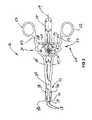
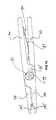
- FIG. 1is a top/side perspective view of a handle assembly and associated clip cartridge of the present invention
- FIG. 2is a top view of the clip applier illustrated in FIG. 1 ;
- FIG. 3is a bottom plan view of the clip applier illustrated in FIG. 1 ;
- FIG. 4is an exploded view of the clip applier illustrating separate handles associated with the handle assembly of the present invention
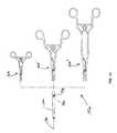
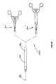
- FIGS. 5-7are side elevation views illustrating a preferred method for mounting the disposable cartridge on the non-disposable handle assembly in a snap fit relationship
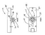
- FIG. 5is a side elevation view of the cartridge being moved toward an operating position on the handle assembly
- FIG. 6is a side elevation view illustrating a snap fit of the cartridge on the fulcrum of the handle assembly
- FIG. 7is a side elevation view illustrating a snap fit relationship between the cartridge and the slots of the handle assembly
- FIG. 8is a side view of a snap fitting carried by the operating pin of the cartridge and adapted for a snap fit into the slots of the handle assembly;
- FIG. 9is a bottom plan view of the snap fitting illustrated in FIG. 8 ;
- FIG. 10is a top plan view of the flanges and associated intersecting slots associated with the handle assembly, the handles of the assembly being shown in an open state;
- FIG. 11is a top plan view similar to FIG. 10 and showing the handles of the assembly in a closed state;
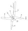
- FIG. 12is a top side perspective view of the handles aligned for assembly or disassembly at a bayonet fitting disposed at the fulcrum of the assembly;
- FIG. 13is a perspective view of a female portion of the bayonet fitting illustrated in FIG. 12 ;
- FIG. 14is a perspective view of a male portion of the bayonet fitting illustrated in FIG. 12 ;
- FIG. 15is a top plan view of the bayonet fitting showing the handles aligned for assembly and further illustrating a locking pin to inhibit disassembly;
- FIG. 16is a top view similar to FIG. 16 and showing the handle assembly in a closed operating position
- FIG. 17is a side elevation view of the handle assembly illustrating areas of increased thickness facilitating stability of the assembly and comfort for the user;
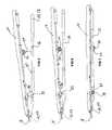
- FIG. 18 - FIG. 21illustrates top plan views of various sizes of handle assemblies adapted for use with various sizes of cartridges and clips;
- FIG. 18illustrates a top plan view of three handles assemblies of the present invention adapted for use with a small-size clip and cartridge
- FIG. 19illustrates three sizes of handle assemblies adapted for use with a medium-size clip and cartridge
- FIG. 20illustrates two handle assemblies adapted for use with a medium-large clip and cartridge
- FIG. 21illustrates two handle assemblies adapted for use with a large-size clip and cartridge
- FIG. 22is a top plan view of a handle assembly of the present invention adapted for alternative use with various end effectors.
- FIG. 1A modular ligating clip applier is illustrated in FIG. 1 and designated by the reference numeral 10 .
- a cartridge 12 containing a train of ligating clips 14is removably carried on and operated by a handle assembly 16 having an axis 17 .
- Jaws 18carried by the cartridge 12 , are adapted to receive the clips, one at a time, and to crimp the received clip onto body tissue, such as a blood vessel of a patient.
- Movement of the jaws 18 from the normally opened state to the closed stateis accomplished by operation of the handle assembly 16 which, in a preferred embodiment, has a scissors configuration.
- the handle assembly 16has a distal end 22 terminating in a pair of pawls 23 and a proximal end 25 terminating in a pair of finger rings 27 .
- the pawls 23extend outwardly of the jaws 18 and are operable by closing the finger rings 27 to move the jaws 18 from the normally opened position to the closed position.
- a modular ligating clip applier of this typeis illustrated and described in U.S. patent application Ser. No. 60/117,079 filed on Jan. 25, 1999 and entitled “Modular Ligating Apparatus and Method” and in PCT/US00/01296 filed on Jan. 19, 2000 and entitled “Modulating Ligating Apparatus and Method.” This application is incorporated herein by reference.
- the scissors configuration of the handle assembly 16is best illustrated in the bottom plan view of FIG. 3 .
- the handle assembly 16includes handles 30 and 32 which are pivotally attached to each other at a fulcrum 34 .
- the handles 30 and 32At the distal end 21 , distally of the fulcrum 34 , the handles 30 and 32 include a pair of arms 36 and 38 , which extend to associated pawls 41 and 43 , respectively.
- the handles 30 and 32include a pair of legs 45 and 47 which are generally aligned with the associated arms 36 and 38 . Disposed proximally of the legs 45 and 47 are a pair of handle bars 50 and 52 which extend to associated finger rings 54 and 56 , respectively.
- the handle 30has a flange 58 which extends inwardly of the leg 45 and the handle bar 50 .
- the flange 58includes a slot 61 and a surface 63 which faces the cartridge 12 .
- the handle 32includes a flange 65 which extends inwardly of the leg 47 and the handle bar 52 .
- the flange 65includes a slot 67 and a surface 70 which faces away from the cartridge 12 .
- the slots 61 and 67 in this embodimentare generally straight and disposed at a common angle relative to the axis 17 . As the handles 30 and 32 pivot on the fulcrum 34 , the slots 61 and 67 intersect at a point which moves progressively along the axis 17 . A button or snap 72 coupled to an operating pin 74 of the cartridge 12 , can be snap fit into the slots 61 and 67 at this point of intersection.
- the separate handles 30 and 32 and the cartridge 12are illustrated in greater detail in the exploded view of FIG. 4 .
- the jaws 18 and snap 72are carried by the cartridge 12 along with a projection 76 .
- this projection 76is maintained in a snap-fit relationship with a bayonet fitting disposed at the fulcrum 34 .
- this bayonet fittingincludes a male component 78 carried by the handle 32 , and a female component 81 carried by the handle 30 .
- the bayonet fittingwhich is discussed in greater detail below, defines a hole 83 into which the projection 76 can be snapped fit when the cartridge 12 is mounted on the handle assembly 16 .
- a locking pin 85 , leaf spring 87 and associated hook 90are discussed in greater detail below.
- FIGS. 5-7A preferred method for mounting the cartridge 12 on the handle assembly 16 is illustrated in the progressive views of FIGS. 5-7 .
- the cartridge 12 and handle assembly 16are shown to be aligned and ready for engagement.
- the jaws 18are positioned between the pawls 41 and 43 .
- the remainder of the cartridge 12is positioned over the axis 17 as shown in the plan view of FIG. 2 .
- the projection 76 on the cartridge 12snaps into the hole 83 on the handle assembly 16 .
- Further pivotal movement of the cartridge 12will cause the snap 72 and associated operating pin 74 to snap into the slots 61 and 67 at their point of intersection, as illustrated in FIG. 3 .
- the cartridge 12is generally parallel to the plane of the handle assembly 16 with the cartridge 12 supported in a removable snap-fit relationship by the projection 76 and the snap 72 .
- these points of connection defined by the projection 76 and snap 72are widely separated by a distance greater than about one-half the length of the cartridge 12 . This aids in stabilizing the cartridge 12 on the handle assembly 16 in the operative position illustrated in FIG. 7 .
- the configuration of the button or snap 72is illustrated in a preferred embodiment shown in the enlarged views of FIGS. 8 and 9 .
- the snap 72is movable on the cartridge 12 which includes a bottom plate 92 and cover 94 .
- the operating pin 74 of the cartridge 12is moveable in a slot 97 which extends through the bottom plate 92 and provides the pin 74 with access into the cover 94 .
- the snap 72can be formed with a flange 96 which is integral with a set of inwardly biased teeth 98 and outwardly biased fingers 101 .
- the snap 72can be snap-fit onto the pin 74 , with the teeth 98 engaging the pin 74 preferably in a non-removable relationship.
- the flange 96 of the snap 72is slidable along with the operating pin 74 along the bottom plate 92 .
- the fingers 101 of the snap 72are biased outwardly with ridges which removably engage the slots 61 and 67 of the handle assembly 16 at their point of intersection, as best illustrated in FIG. 3 .
- the slots 61 , 67 and the commensurate movement of the snap 72 and operating pin 74can be better understood with reference to FIG. 10 wherein the handle assembly 16 is shown in the opened state, and FIG. 11 wherein the handle assembly 16 is shown in the closed state.
- the slots 61 and 67are generally straight and extend along respective axes 103 and 105 .
- the slot 61 of the handlescan be angled proximally and outwardly to define an angle ⁇ between the axis 17 of the handle assembly 16 and the axis 103 of the slot 61 .
- the slot 67 of the handle 32can be angled proximally and outwardly to define an angle ⁇ between the axis 17 of the handle assembly 16 and the axis 105 of the slot 67 .
- the slots 61 and 67are shown to intersect at a distal point of the intersection 107 which defines the distal most position for the snap 72 and operating pin 74 .
- the point of intersection defined by the slots 61 and 67moves from the distal point of intersection of 107 toward a proximal point of intersection 109 .
- the proximal point of intersection 109defines the proximal-most position of the snap 72 and operating pin 74 .
- the pin 74 of the cartridge 12can be moved along the axis 17 between the points 107 and 109 .
- the slots 61 and 67pivot with the associated handles 30 and 32 on the fulcrum 34 as illustrated in FIG. 3 .
- the angles ⁇ and ⁇measured between the axis 17 and the respective axes 103 and 105 , will vary as the handles 30 , 32 are moved between the opened position ( FIG. 10 ) and closed position (FIG. 11 ).
- the sum of the angles ⁇ and ⁇ in the opened positionis equal to about 59 degrees.
- the sum of the angles ⁇ and ⁇is equal to about 49 degrees.
- the shapes of the slots 61 and 67 , their relative positions, and their positions relative to the axis 17dictate the timing, direction and velocity of movement for the pin 74 .
- the pin 74will move at a generally constant rate between the points 107 and 109 .
- the slots 61 and 67may have different shapes, may be cured, or may have different relationships with respect to the axis 17 .
- FIG. 12shows the structure and method associated with assembling the handles 30 and 32 of the handle assembly 16 .
- the structure of the bayonet fittings 78 and 81 associated with the handles 32 and 30 , respectively,are of particular interest in FIG. 12 and the enlarged views of FIGS. 13 and 14 .
- the female fitting 81can be formed in a section 112 of the handle 30 which has been machined to provide a reduced thickness and an alignment surface 114 .
- the female fitting 81can be formed as a circular hole with a pair of flanges 116 extended into the hole from opposite directions. Each of these flanges is provided with an outwardly facing shoulder 118 which engages the male fitting 78 .
- a similar section 121can be formed with a reduced thickness and an inwardly facing alignment surface 123 .
- the male fitting 78is provided with the configuration of a cylinder 125 which defines the interior hole 83 for the projection 76 (FIG. 4 ).
- Extending outwardly of the cylinder 125are a pair of opposing flanges 127 and 130 .
- the handles 30 and 32can be positioned as illustrated in FIG. 12 at a relative angle such as 110 degrees so that the flanges 127 and 130 of the male fitting 78 can be received between the flanges 116 of the female fitting 81 .
- the handles 30 and 32can be moved toward the closed position as illustrated in FIG. 15 . With this pivotal movement, the flanges 127 and 130 associated with the male fitting 78 will ride along the shoulders 118 associated with the flanges 116 of the female fitting 81 . Ultimately the handles 30 and 32 can be moved to the closed position as illustrated in FIG. 16 .
- bayonet fittings 78 and 81not only provide a high level of structural but also facilitate both assembly and disassembly of the handles 30 and 32 . Disassembly can be of particular interest in the cleaning of the handles 30 and 32 . By separating the fittings 78 and 81 , all surfaces of the handles 30 and 32 are exposed so that there are no hidden compartments containing contaminants or debris.
- a pin hole 132can be provided as illustrated in FIG. 13 .
- This holeis sized and configured to receive the locking pin 85 ( FIG. 4 ) which extends slightly into the circular opening associated with the female fitting 81 .
- the pin 85can prevent disassembly of the handles 30 and 32 if that feature is preferred in a particular embodiment.
- FIG. 16the pin 85 is shown with the bayonet fittings 78 and 81 and the handles 30 and 32 in the closed position.
- FIG. 16also illustrates another aspect of the present invention wherein the leaf spring 87 on the handle 32 engages the hook 90 on the handle 30 .
- This leaf spring 87biases the handles 30 and 32 toward the open state.
- the hook 90rides within a slot at the proximal end of the leaf spring 87 .
- this slotis closed; so the leaf spring 87 and associated hook, when engaged, will limit further separation of the handles 30 and 32 .
- the lead spring 87can be removed from the hook 90 as illustrated in FIG. 12 .
- FIG. 17Another aspect of the invention is illustrated in the side elevation view of FIG. 17 .
- a preferred embodiment of the handle assembly 16provides for areas of increased thickness and areas of decreased thickness. This particular structure provides increased balance and improved tactile feedback for the surgeon. It has been found that by increasing the thickness of the handle assembly 16 in the areas of the fulcrum 34 and the finger rings 54 and 56 , greater balance can be achieved for the instrument. This provides a reduced area of thickness between the two increased areas of thickness and thereby improves the balance and feel of the instrument.
- the thickness of the handle assembly 16 at the fulcrum 34is about ⁇ fraction (3/16) ⁇ inch. This same thickness is maintained at the finger rings 54 and 56 . In the region between these two areas, the handles 30 and 32 are provided with a reduced thickness such as 1 ⁇ 8 inch to balance the instrument.
- FIG. 2Another feature of the present invention is associated with the handle bars 50 and 52 , perhaps best illustrated in FIG. 2 . It has been found that many of the surgeons using modular clip appliers, operate the device by “palming” the handle assembly. Rather than placing their fingers within the finger rings 54 and 56 , the handles are engaged by the palm of the hand. With this orientation the fingers extend along one of the handles, such as the handle 30 , while the thumb extends along the other handle, such as the handle 32 . In order to facilitate palming of the present handle assembly 16 , the legs 45 and 47 which intersect at the fulcrum 34 , do not extend in straight lines to the finger rings 54 and 56 , respectively.
- these legs 45 and 47diverge outwardly to the handle bars 50 and 52 respectively, which then extend to the finger rings 54 and 56 .
- These handle bars 50 and 52which may also be straight in configuration, are disposed on imaginary lines 134 and 136 , respectively which converge distally to a point that is distal of the fulcrum 34 .
- This structureprovides the handles 30 and 32 with a remote configuration near the fulcrum 34 , which facilitates reaching into narrow areas of the body. More proximally, near the finger rings 54 and 56 , the handles 30 and 32 have a wider construction at the handle bars 50 and 52 which facilitates the palming aspect of the present invention. This wider configuration is achieved even though the handle bars 50 and 52 may be parallel to the legs 32 and 30 , respectively. Ridges 138 and 141 can be provided along the respective handle bars 50 and 52 in order to facilitate finger placement and inhibit sliding of the handle assembly 16 in the user's hand.
- the clips 14are traditionally provided in four different sizes: a small clip having a width of about 1 ⁇ 8 inch; a medium clip having a width about ⁇ fraction (3/16) ⁇ inch; a medium-large clip having a width of about 1 ⁇ 4 inch; and a large clip having a width approaching 3 ⁇ 8 inches.
- These four clipsare illustrated in the respective views of FIGS. 18 , 19 , 20 and 21 where elements of similar structure are designated by the same reference numeral followed by the respective lower-case letters “a”, ”b”, “c”, and “d”.
- the clipis designated by the reference numeral 14 a while in FIG. 21 the clip is designated by the reference numeral 14 a.
- a dedicated group of handle assemblies 143 amay be desired for each of the clips and its associated cartridge. Such a group is designated by the reference numeral 143 a in FIG. 18 .
- the small clip 14 acan be housed in a small cartridge 12 a having a length such as six inches.
- the dedicated handle assembliesmay include a short handle assembly 16 a , a medium handle assembly 16 a ′, and a long handle assembly 16 a ′′.
- the group of dedicated handle assemblies 143 awill enable a user to select a handle assembly which is sufficiently long to reach the operative site but sufficiently short to maximize manipulation of the cartridge 12 a .
- the short handle assembly 16 ahas the length of about six inches
- the medium handle assembly 16 a ′′has a length of about 8 inches
- the long handle assembly 16 a ′′has the length of about 11 inches.
- the medium-sized clip 14 bis capable of being housed in the cartridge 12 b having a length such as seven inches.
- the group of dedicated handle assemblies 143 bincludes a short handle assembly 16 b , a medium handle assembly 16 b ′ and a long handle assembly 16 b ′′.
- each of the handle assemblies in the group 143 bwill typically be longer than the associated handle assemblies in the group 143 a (FIG. 18 ).
- placement of the flanges 58 b and 65 b and the associated slots 61 b and 67 bmay also vary.
- the medium-large clip 14 cis adapted to be carried in the cartridge 12 c which may have a length of about 22.37 cm (8.809 in).
- This cartridge 12 ccan be adapted for use with a group of dedicated handle assemblies designated by the reference number 143 c . These assemblies include a medium handle assembly 16 c ′, and large handle assembly 16 c ′′. Once again, each of the handle assemblies in this group 143 c may be longer than the associated assembly in the group 143 b (FIG. 19 ).
- the cartridge 12 dmay nevertheless be adapted for use with the same group of handle assemblies 143 c previously discussed.
- the handle assemblies 16 c ′ and 16 c ′′ mentioned with respect to FIG. 20can be used to operate the cartridge 12 d illustrated in FIG. 21 .
- This universal group 143 c of handle assembliescan function with different sizes of the clips 14 c and 14 d , as well as the different sizes of cartridges 12 c and 12 d .
- the slots 61 c and 67 ccan be made sufficiently long to accommodate the pin 74 d , with the pin 74 c using less than the entire length of the slots 61 c and 67 c.
- overdrive protectionis provided in order to prevent closure of the handles 30 and 32 beyond the point required by the cartridge 12 .
- this overdrive protectionis provided in several locations. For example, with reference to FIG. 16 , it will be noted that interfering lugs 145 and 147 can be provided on the respective arms 36 and 38 . When these lugs 145 and 147 come into contact, further closure of the handles 30 and 32 is prevented.
- lugs 150 and 152are created on the associated handles 30 and 32 . These lugs 150 and 152 have an interference fit with the opposing handle 32 and 30 , respectively, at the point of maximum closure.
- the end effectorsuch as the jaws of a staple cartridge are permanently or removable attached to the handle assembly, improved alignment and stability is always of interest.
- Other end effectors contemplatedmight include shears, scissors, graspers, clips, clamps and clinches, for example.
- the end effectorsuch as the staple jaws 18
- the end effectorcan be mounted on a disposable carrier, such as a staple cartridge that is removably attached to a non-disposable handle assembly.
- the inventioncontemplates a disposable portion and a non-disposable portion.
- the disposable portionsuch as the cartridge 12
- the end effectorssuch as the jaws 18
- an associated structurefor maintaining alignment of the end effectors.
- the non-disposable portionincludes the handle assembly which can be sterilized, typically by autoclaving to facilitate repeated use of this non-disposable portion.
- the disposable portionis intended to be carried by the non-disposable portion, as the cartridge 12 is carried by the handle assembly 16 . More specifically, the cartridge 12 can be removably attached to the handle assembly 16 to facilitate assembly and disassembly of the disposable portion from the non-disposable portion. In a preferred embodiment, this attachment of the disposable portion to the non-disposable portion is accomplished without attaching the end effectors, such as the jaws 18 , to either the arms 36 , 38 , or the pawls 41 , 43 . Rather, the end effectors are free to move or float relative to the arms 36 , 38 and the pawls 41 , 43 .
- the alignment of the end effectoris dependent upon only the alignment structure within the disposable portion, such as the cartridge 12 .
- the jaws 18floating relative to the arms 36 , 38 and the pawls, 41 , 43 , their alignment is independent of the alignment of the handle assembly 16 .
- the handle assembly 16Since the handle assembly 16 is intended to be non-disposable, it is the structure most likely to receive severe treatment sometimes associated with the sterilizing or autoclaving process. This treatment is most likely to produce any misalignment associated with the combination.
- the disposable portion or cartridge 12is new to the combination each time the handle assembly 16 is used. This brings to the combination not only new end effectors, such as the jaws 18 , but also new alignment structure for the end effectors.
- FIG. 22illustrates a handle assembly 16 adapted for alternative use with three types of end effectors, namely, a scissors end effector 160 , a graspers end effector 162 , and the clip applier end effector 165 which includes the jaws 18 .
- the end effectorhas its own alignment structure.
- the graspers end effector 162includes grasper jaws 166 and an associated alignment structure 168 . From this view, it can be further appreciated that misalignment of the handle assembly 16 will not effect the alignment of the jaws 166 which are independently aligned by the structure 168 .
Landscapes
- Health & Medical Sciences (AREA)
- Surgery (AREA)
- Life Sciences & Earth Sciences (AREA)
- Heart & Thoracic Surgery (AREA)
- Nuclear Medicine, Radiotherapy & Molecular Imaging (AREA)
- Vascular Medicine (AREA)
- Engineering & Computer Science (AREA)
- Biomedical Technology (AREA)
- Reproductive Health (AREA)
- Medical Informatics (AREA)
- Molecular Biology (AREA)
- Animal Behavior & Ethology (AREA)
- General Health & Medical Sciences (AREA)
- Public Health (AREA)
- Veterinary Medicine (AREA)
- Surgical Instruments (AREA)
Abstract
Description
Claims (23)
Priority Applications (2)
| Application Number | Priority Date | Filing Date | Title |
|---|---|---|---|
| US09/675,851US6896683B1 (en) | 1999-01-25 | 2000-09-28 | Surgical instrument with improved handle assembly |
| US11/021,852US7731725B2 (en) | 1999-01-25 | 2004-12-23 | Surgical instrument with improved handle assembly |
Applications Claiming Priority (3)
| Application Number | Priority Date | Filing Date | Title |
|---|---|---|---|
| US11707999P | 1999-01-25 | 1999-01-25 | |
| PCT/US2000/001296WO2000042922A1 (en) | 1999-01-25 | 2000-01-19 | Modular ligating apparatus and method |
| US09/675,851US6896683B1 (en) | 1999-01-25 | 2000-09-28 | Surgical instrument with improved handle assembly |
Related Parent Applications (1)
| Application Number | Title | Priority Date | Filing Date |
|---|---|---|---|
| PCT/US2000/001296ContinuationWO2000042922A1 (en) | 1999-01-25 | 2000-01-19 | Modular ligating apparatus and method |
Related Child Applications (1)
| Application Number | Title | Priority Date | Filing Date |
|---|---|---|---|
| US11/021,852DivisionUS7731725B2 (en) | 1999-01-25 | 2004-12-23 | Surgical instrument with improved handle assembly |
Publications (1)
| Publication Number | Publication Date |
|---|---|
| US6896683B1true US6896683B1 (en) | 2005-05-24 |
Family
ID=34594185
Family Applications (2)
| Application Number | Title | Priority Date | Filing Date |
|---|---|---|---|
| US09/675,851Expired - LifetimeUS6896683B1 (en) | 1999-01-25 | 2000-09-28 | Surgical instrument with improved handle assembly |
| US11/021,852Expired - Fee RelatedUS7731725B2 (en) | 1999-01-25 | 2004-12-23 | Surgical instrument with improved handle assembly |
Family Applications After (1)
| Application Number | Title | Priority Date | Filing Date |
|---|---|---|---|
| US11/021,852Expired - Fee RelatedUS7731725B2 (en) | 1999-01-25 | 2004-12-23 | Surgical instrument with improved handle assembly |
Country Status (1)
| Country | Link |
|---|---|
| US (2) | US6896683B1 (en) |
Cited By (58)
| Publication number | Priority date | Publication date | Assignee | Title |
|---|---|---|---|---|
| US20050222588A1 (en)* | 2004-03-30 | 2005-10-06 | Frans Vandenbroek | Convertible surgical clip applier system |
| US20070073314A1 (en)* | 2005-09-29 | 2007-03-29 | Applied Medical Resources Corporation | Manually actuated surgical clip applier |
| US7655004B2 (en) | 2007-02-15 | 2010-02-02 | Ethicon Endo-Surgery, Inc. | Electroporation ablation apparatus, system, and method |
| US7815662B2 (en) | 2007-03-08 | 2010-10-19 | Ethicon Endo-Surgery, Inc. | Surgical suture anchors and deployment device |
| US8037591B2 (en) | 2009-02-02 | 2011-10-18 | Ethicon Endo-Surgery, Inc. | Surgical scissors |
| US8070759B2 (en) | 2008-05-30 | 2011-12-06 | Ethicon Endo-Surgery, Inc. | Surgical fastening device |
| US8075572B2 (en) | 2007-04-26 | 2011-12-13 | Ethicon Endo-Surgery, Inc. | Surgical suturing apparatus |
| US8100922B2 (en) | 2007-04-27 | 2012-01-24 | Ethicon Endo-Surgery, Inc. | Curved needle suturing tool |
| US8114119B2 (en) | 2008-09-09 | 2012-02-14 | Ethicon Endo-Surgery, Inc. | Surgical grasping device |
| US8114072B2 (en) | 2008-05-30 | 2012-02-14 | Ethicon Endo-Surgery, Inc. | Electrical ablation device |
| US8157834B2 (en) | 2008-11-25 | 2012-04-17 | Ethicon Endo-Surgery, Inc. | Rotational coupling device for surgical instrument with flexible actuators |
| US8172772B2 (en) | 2008-12-11 | 2012-05-08 | Ethicon Endo-Surgery, Inc. | Specimen retrieval device |
| US8211125B2 (en) | 2008-08-15 | 2012-07-03 | Ethicon Endo-Surgery, Inc. | Sterile appliance delivery device for endoscopic procedures |
| US8241204B2 (en) | 2008-08-29 | 2012-08-14 | Ethicon Endo-Surgery, Inc. | Articulating end cap |
| US8252057B2 (en) | 2009-01-30 | 2012-08-28 | Ethicon Endo-Surgery, Inc. | Surgical access device |
| US8262680B2 (en) | 2008-03-10 | 2012-09-11 | Ethicon Endo-Surgery, Inc. | Anastomotic device |
| US8262655B2 (en) | 2007-11-21 | 2012-09-11 | Ethicon Endo-Surgery, Inc. | Bipolar forceps |
| US8262563B2 (en) | 2008-07-14 | 2012-09-11 | Ethicon Endo-Surgery, Inc. | Endoscopic translumenal articulatable steerable overtube |
| US8317806B2 (en) | 2008-05-30 | 2012-11-27 | Ethicon Endo-Surgery, Inc. | Endoscopic suturing tension controlling and indication devices |
| US8337394B2 (en) | 2008-10-01 | 2012-12-25 | Ethicon Endo-Surgery, Inc. | Overtube with expandable tip |
| US8353487B2 (en) | 2009-12-17 | 2013-01-15 | Ethicon Endo-Surgery, Inc. | User interface support devices for endoscopic surgical instruments |
| US8361112B2 (en) | 2008-06-27 | 2013-01-29 | Ethicon Endo-Surgery, Inc. | Surgical suture arrangement |
| US8361066B2 (en) | 2009-01-12 | 2013-01-29 | Ethicon Endo-Surgery, Inc. | Electrical ablation devices |
| US8403926B2 (en) | 2008-06-05 | 2013-03-26 | Ethicon Endo-Surgery, Inc. | Manually articulating devices |
| US8409200B2 (en) | 2008-09-03 | 2013-04-02 | Ethicon Endo-Surgery, Inc. | Surgical grasping device |
| US8480657B2 (en) | 2007-10-31 | 2013-07-09 | Ethicon Endo-Surgery, Inc. | Detachable distal overtube section and methods for forming a sealable opening in the wall of an organ |
| US8480689B2 (en) | 2008-09-02 | 2013-07-09 | Ethicon Endo-Surgery, Inc. | Suturing device |
| US8496574B2 (en) | 2009-12-17 | 2013-07-30 | Ethicon Endo-Surgery, Inc. | Selectively positionable camera for surgical guide tube assembly |
| US8506564B2 (en) | 2009-12-18 | 2013-08-13 | Ethicon Endo-Surgery, Inc. | Surgical instrument comprising an electrode |
| US8529563B2 (en) | 2008-08-25 | 2013-09-10 | Ethicon Endo-Surgery, Inc. | Electrical ablation devices |
| US8568410B2 (en) | 2007-08-31 | 2013-10-29 | Ethicon Endo-Surgery, Inc. | Electrical ablation surgical instruments |
| US8579897B2 (en) | 2007-11-21 | 2013-11-12 | Ethicon Endo-Surgery, Inc. | Bipolar forceps |
| US8608652B2 (en) | 2009-11-05 | 2013-12-17 | Ethicon Endo-Surgery, Inc. | Vaginal entry surgical devices, kit, system, and method |
| US8652150B2 (en) | 2008-05-30 | 2014-02-18 | Ethicon Endo-Surgery, Inc. | Multifunction surgical device |
| US8679003B2 (en) | 2008-05-30 | 2014-03-25 | Ethicon Endo-Surgery, Inc. | Surgical device and endoscope including same |
| US8771260B2 (en) | 2008-05-30 | 2014-07-08 | Ethicon Endo-Surgery, Inc. | Actuating and articulating surgical device |
| US8828031B2 (en) | 2009-01-12 | 2014-09-09 | Ethicon Endo-Surgery, Inc. | Apparatus for forming an anastomosis |
| US8888792B2 (en) | 2008-07-14 | 2014-11-18 | Ethicon Endo-Surgery, Inc. | Tissue apposition clip application devices and methods |
| US8906035B2 (en) | 2008-06-04 | 2014-12-09 | Ethicon Endo-Surgery, Inc. | Endoscopic drop off bag |
| US8939897B2 (en) | 2007-10-31 | 2015-01-27 | Ethicon Endo-Surgery, Inc. | Methods for closing a gastrotomy |
| US8986199B2 (en) | 2012-02-17 | 2015-03-24 | Ethicon Endo-Surgery, Inc. | Apparatus and methods for cleaning the lens of an endoscope |
| US9005198B2 (en) | 2010-01-29 | 2015-04-14 | Ethicon Endo-Surgery, Inc. | Surgical instrument comprising an electrode |
| US9028483B2 (en) | 2009-12-18 | 2015-05-12 | Ethicon Endo-Surgery, Inc. | Surgical instrument comprising an electrode |
| US9049987B2 (en) | 2011-03-17 | 2015-06-09 | Ethicon Endo-Surgery, Inc. | Hand held surgical device for manipulating an internal magnet assembly within a patient |
| US9078662B2 (en) | 2012-07-03 | 2015-07-14 | Ethicon Endo-Surgery, Inc. | Endoscopic cap electrode and method for using the same |
| US9226772B2 (en) | 2009-01-30 | 2016-01-05 | Ethicon Endo-Surgery, Inc. | Surgical device |
| US9233241B2 (en) | 2011-02-28 | 2016-01-12 | Ethicon Endo-Surgery, Inc. | Electrical ablation devices and methods |
| US9254169B2 (en) | 2011-02-28 | 2016-02-09 | Ethicon Endo-Surgery, Inc. | Electrical ablation devices and methods |
| US9277957B2 (en) | 2012-08-15 | 2016-03-08 | Ethicon Endo-Surgery, Inc. | Electrosurgical devices and methods |
| US9314620B2 (en) | 2011-02-28 | 2016-04-19 | Ethicon Endo-Surgery, Inc. | Electrical ablation devices and methods |
| US9427255B2 (en) | 2012-05-14 | 2016-08-30 | Ethicon Endo-Surgery, Inc. | Apparatus for introducing a steerable camera assembly into a patient |
| US9545290B2 (en) | 2012-07-30 | 2017-01-17 | Ethicon Endo-Surgery, Inc. | Needle probe guide |
| US9572623B2 (en) | 2012-08-02 | 2017-02-21 | Ethicon Endo-Surgery, Inc. | Reusable electrode and disposable sheath |
| US10092291B2 (en) | 2011-01-25 | 2018-10-09 | Ethicon Endo-Surgery, Inc. | Surgical instrument with selectively rigidizable features |
| US10098527B2 (en) | 2013-02-27 | 2018-10-16 | Ethidcon Endo-Surgery, Inc. | System for performing a minimally invasive surgical procedure |
| US10314649B2 (en) | 2012-08-02 | 2019-06-11 | Ethicon Endo-Surgery, Inc. | Flexible expandable electrode and method of intraluminal delivery of pulsed power |
| US10779882B2 (en) | 2009-10-28 | 2020-09-22 | Ethicon Endo-Surgery, Inc. | Electrical ablation devices |
| US20210330328A1 (en)* | 2020-04-24 | 2021-10-28 | NeuraMedica Inc. | Clips, Appliers, and Cartridges |
Families Citing this family (120)
| Publication number | Priority date | Publication date | Assignee | Title |
|---|---|---|---|---|
| EP1608272B1 (en) | 2003-03-11 | 2017-01-25 | Covidien LP | Clip applying apparatus with angled jaw |
| US8714429B2 (en)* | 2003-04-29 | 2014-05-06 | Covidien Lp | Dissecting tip for surgical stapler |
| US7819886B2 (en) | 2004-10-08 | 2010-10-26 | Tyco Healthcare Group Lp | Endoscopic surgical clip applier |
| EP2641548B1 (en) | 2004-10-08 | 2015-08-19 | Covidien LP | Endoscopic surgical clip applier |
| US8409222B2 (en) | 2004-10-08 | 2013-04-02 | Covidien Lp | Endoscopic surgical clip applier |
| CA2809110A1 (en) | 2004-10-08 | 2006-04-20 | Tyco Healthcare Group Lp | Apparatus for applying surgical clips |
| US9763668B2 (en) | 2004-10-08 | 2017-09-19 | Covidien Lp | Endoscopic surgical clip applier |
| US8603106B2 (en) | 2005-05-20 | 2013-12-10 | Neotract, Inc. | Integrated handle assembly for anchor delivery system |
| US8628542B2 (en) | 2005-05-20 | 2014-01-14 | Neotract, Inc. | Median lobe destruction apparatus and method |
| US10925587B2 (en) | 2005-05-20 | 2021-02-23 | Neotract, Inc. | Anchor delivery system |
| US8668705B2 (en) | 2005-05-20 | 2014-03-11 | Neotract, Inc. | Latching anchor device |
| US7645286B2 (en) | 2005-05-20 | 2010-01-12 | Neotract, Inc. | Devices, systems and methods for retracting, lifting, compressing, supporting or repositioning tissues or anatomical structures |
| US7758594B2 (en) | 2005-05-20 | 2010-07-20 | Neotract, Inc. | Devices, systems and methods for treating benign prostatic hyperplasia and other conditions |
| US9549739B2 (en) | 2005-05-20 | 2017-01-24 | Neotract, Inc. | Devices, systems and methods for treating benign prostatic hyperplasia and other conditions |
| US10195014B2 (en) | 2005-05-20 | 2019-02-05 | Neotract, Inc. | Devices, systems and methods for treating benign prostatic hyperplasia and other conditions |
| CA2605135C (en) | 2006-10-17 | 2014-12-30 | Tyco Healthcare Group Lp | Apparatus for applying surgical clips |
| EP2157920B1 (en) | 2007-03-26 | 2017-09-27 | Covidien LP | Endoscopic surgical clip applier |
| CN102327136B (en) | 2007-04-11 | 2014-04-23 | 柯惠Lp公司 | Surgical clip applier |
| US8496684B2 (en)* | 2007-10-31 | 2013-07-30 | Ethicon Endo-Surgery, Inc. | Method for deploying a device for gastric volume reduction |
| US20100023024A1 (en)* | 2008-07-25 | 2010-01-28 | Zeiner Mark S | Reloadable laparoscopic fastener deploying device with disposable cartridge for use in a gastric volume reduction procedure |
| US20100023025A1 (en)* | 2008-07-25 | 2010-01-28 | Zeiner Mark S | Reloadable laparoscopic fastener deploying device with disposable cartridge for use in a gastric volume reduction procedure |
| US20100023022A1 (en)* | 2008-07-25 | 2010-01-28 | Zeiner Mark S | Reloadable laparoscopic fastener deploying device with disposable cartridge use in a gastric volume reduction procedure |
| US20100023026A1 (en)* | 2008-07-25 | 2010-01-28 | Zeiner Mark S | Reloadable laparoscopic fastener deploying device with disposable cartridge for use in a gastric volume reduction procedure |
| US20110208212A1 (en) | 2010-02-19 | 2011-08-25 | Zergiebel Earl M | Surgical clip applier |
| US8056565B2 (en) | 2008-08-25 | 2011-11-15 | Tyco Healthcare Group Lp | Surgical clip applier and method of assembly |
| US8465502B2 (en) | 2008-08-25 | 2013-06-18 | Covidien Lp | Surgical clip applier and method of assembly |
| US8267944B2 (en) | 2008-08-29 | 2012-09-18 | Tyco Healthcare Group Lp | Endoscopic surgical clip applier with lock out |
| US8409223B2 (en) | 2008-08-29 | 2013-04-02 | Covidien Lp | Endoscopic surgical clip applier with clip retention |
| US8585717B2 (en) | 2008-08-29 | 2013-11-19 | Covidien Lp | Single stroke endoscopic surgical clip applier |
| US9358015B2 (en) | 2008-08-29 | 2016-06-07 | Covidien Lp | Endoscopic surgical clip applier with wedge plate |
| JP2010193994A (en)* | 2009-02-24 | 2010-09-09 | Fujifilm Corp | Clip package, multiple clip system, and mechanism for preventing mismatch of the multiple clip system |
| US8734469B2 (en) | 2009-10-13 | 2014-05-27 | Covidien Lp | Suture clip applier |
| US9186136B2 (en) | 2009-12-09 | 2015-11-17 | Covidien Lp | Surgical clip applier |
| US8545486B2 (en) | 2009-12-15 | 2013-10-01 | Covidien Lp | Surgical clip applier |
| US8403945B2 (en) | 2010-02-25 | 2013-03-26 | Covidien Lp | Articulating endoscopic surgical clip applier |
| US8403946B2 (en) | 2010-07-28 | 2013-03-26 | Covidien Lp | Articulating clip applier cartridge |
| US8968337B2 (en) | 2010-07-28 | 2015-03-03 | Covidien Lp | Articulating clip applier |
| US9011464B2 (en) | 2010-11-02 | 2015-04-21 | Covidien Lp | Self-centering clip and jaw |
| US9186153B2 (en) | 2011-01-31 | 2015-11-17 | Covidien Lp | Locking cam driver and jaw assembly for clip applier |
| US9775623B2 (en) | 2011-04-29 | 2017-10-03 | Covidien Lp | Surgical clip applier including clip relief feature |
| US20130131697A1 (en) | 2011-11-21 | 2013-05-23 | Covidien Lp | Surgical clip applier |
| US9364239B2 (en) | 2011-12-19 | 2016-06-14 | Covidien Lp | Jaw closure mechanism for a surgical clip applier |
| US9364216B2 (en) | 2011-12-29 | 2016-06-14 | Covidien Lp | Surgical clip applier with integrated clip counter |
| WO2013138927A1 (en)* | 2012-03-20 | 2013-09-26 | Adamson Systems Engineering Inc. | Audio system with integrated power, audio signal and control distribution |
| US10292801B2 (en) | 2012-03-29 | 2019-05-21 | Neotract, Inc. | System for delivering anchors for treating incontinence |
| EP2833802A4 (en)* | 2012-04-04 | 2015-11-18 | Cardica Inc | Surgical staple cartridge with bendable tip |
| US9408610B2 (en) | 2012-05-04 | 2016-08-09 | Covidien Lp | Surgical clip applier with dissector |
| US9532787B2 (en) | 2012-05-31 | 2017-01-03 | Covidien Lp | Endoscopic clip applier |
| US10130353B2 (en) | 2012-06-29 | 2018-11-20 | Neotract, Inc. | Flexible system for delivering an anchor |
| US9113892B2 (en) | 2013-01-08 | 2015-08-25 | Covidien Lp | Surgical clip applier |
| US9968362B2 (en) | 2013-01-08 | 2018-05-15 | Covidien Lp | Surgical clip applier |
| US9750500B2 (en) | 2013-01-18 | 2017-09-05 | Covidien Lp | Surgical clip applier |
| US9775624B2 (en) | 2013-08-27 | 2017-10-03 | Covidien Lp | Surgical clip applier |
| US9707005B2 (en) | 2014-02-14 | 2017-07-18 | Ethicon Llc | Lockout mechanisms for surgical devices |
| US10702278B2 (en) | 2014-12-02 | 2020-07-07 | Covidien Lp | Laparoscopic surgical ligation clip applier |
| US9931124B2 (en) | 2015-01-07 | 2018-04-03 | Covidien Lp | Reposable clip applier |
| CN107205747B (en) | 2015-01-15 | 2020-09-08 | 柯惠有限合伙公司 | Reusable endoscopic surgical clip applier |
| US10292712B2 (en) | 2015-01-28 | 2019-05-21 | Covidien Lp | Surgical clip applier with integrated cutter |
| US10159491B2 (en) | 2015-03-10 | 2018-12-25 | Covidien Lp | Endoscopic reposable surgical clip applier |
| CN108348259B (en) | 2015-11-03 | 2020-12-11 | 柯惠有限合伙公司 | Endoscopic Surgical Fixture Applicator |
| US10390831B2 (en) | 2015-11-10 | 2019-08-27 | Covidien Lp | Endoscopic reposable surgical clip applier |
| US10905425B2 (en) | 2015-11-10 | 2021-02-02 | Covidien Lp | Endoscopic reposable surgical clip applier |
| US10702280B2 (en) | 2015-11-10 | 2020-07-07 | Covidien Lp | Endoscopic reposable surgical clip applier |
| CN108472044B (en) | 2016-01-11 | 2021-04-16 | 柯惠有限合伙公司 | endoscope-reserved surgical clip applier |
| AU2016388454A1 (en) | 2016-01-18 | 2018-07-19 | Covidien Lp | Endoscopic surgical clip applier |
| CA2958160A1 (en) | 2016-02-24 | 2017-08-24 | Covidien Lp | Endoscopic reposable surgical clip applier |
| WO2018027788A1 (en) | 2016-08-11 | 2018-02-15 | Covidien Lp | Endoscopic surgical clip applier and clip applying systems |
| CN109640844B (en) | 2016-08-25 | 2021-08-06 | 柯惠Lp公司 | Endoscopic Surgical Clip Appliers and Applicator Systems |
| US10639044B2 (en) | 2016-10-31 | 2020-05-05 | Covidien Lp | Ligation clip module and clip applier |
| US10660651B2 (en) | 2016-10-31 | 2020-05-26 | Covidien Lp | Endoscopic reposable surgical clip applier |
| US10610236B2 (en) | 2016-11-01 | 2020-04-07 | Covidien Lp | Endoscopic reposable surgical clip applier |
| US10426489B2 (en) | 2016-11-01 | 2019-10-01 | Covidien Lp | Endoscopic reposable surgical clip applier |
| US10492795B2 (en) | 2016-11-01 | 2019-12-03 | Covidien Lp | Endoscopic surgical clip applier |
| US10709455B2 (en) | 2017-02-02 | 2020-07-14 | Covidien Lp | Endoscopic surgical clip applier |
| US11116514B2 (en) | 2017-02-06 | 2021-09-14 | Covidien Lp | Surgical clip applier with user feedback feature |
| US10758244B2 (en) | 2017-02-06 | 2020-09-01 | Covidien Lp | Endoscopic surgical clip applier |
| US10660725B2 (en) | 2017-02-14 | 2020-05-26 | Covidien Lp | Endoscopic surgical clip applier including counter assembly |
| US10603038B2 (en) | 2017-02-22 | 2020-03-31 | Covidien Lp | Surgical clip applier including inserts for jaw assembly |
| US10548602B2 (en) | 2017-02-23 | 2020-02-04 | Covidien Lp | Endoscopic surgical clip applier |
| US11583291B2 (en) | 2017-02-23 | 2023-02-21 | Covidien Lp | Endoscopic surgical clip applier |
| US10675043B2 (en) | 2017-05-04 | 2020-06-09 | Covidien Lp | Reposable multi-fire surgical clip applier |
| US10722235B2 (en) | 2017-05-11 | 2020-07-28 | Covidien Lp | Spring-release surgical clip |
| US10639032B2 (en) | 2017-06-30 | 2020-05-05 | Covidien Lp | Endoscopic surgical clip applier including counter assembly |
| US10660723B2 (en) | 2017-06-30 | 2020-05-26 | Covidien Lp | Endoscopic reposable surgical clip applier |
| US10675112B2 (en) | 2017-08-07 | 2020-06-09 | Covidien Lp | Endoscopic surgical clip applier including counter assembly |
| US10932790B2 (en) | 2017-08-08 | 2021-03-02 | Covidien Lp | Geared actuation mechanism and surgical clip applier including the same |
| US10863992B2 (en) | 2017-08-08 | 2020-12-15 | Covidien Lp | Endoscopic surgical clip applier |
| US10786262B2 (en) | 2017-08-09 | 2020-09-29 | Covidien Lp | Endoscopic reposable surgical clip applier |
| US10786263B2 (en) | 2017-08-15 | 2020-09-29 | Covidien Lp | Endoscopic reposable surgical clip applier |
| US10835341B2 (en) | 2017-09-12 | 2020-11-17 | Covidien Lp | Endoscopic surgical clip applier and handle assemblies for use therewith |
| US10758245B2 (en) | 2017-09-13 | 2020-09-01 | Covidien Lp | Clip counting mechanism for surgical clip applier |
| US10653429B2 (en) | 2017-09-13 | 2020-05-19 | Covidien Lp | Endoscopic surgical clip applier |
| US10835260B2 (en) | 2017-09-13 | 2020-11-17 | Covidien Lp | Endoscopic surgical clip applier and handle assemblies for use therewith |
| US10945734B2 (en) | 2017-11-03 | 2021-03-16 | Covidien Lp | Rotation knob assemblies and surgical instruments including the same |
| US11116513B2 (en) | 2017-11-03 | 2021-09-14 | Covidien Lp | Modular surgical clip cartridge |
| US11376015B2 (en) | 2017-11-03 | 2022-07-05 | Covidien Lp | Endoscopic surgical clip applier and handle assemblies for use therewith |
| US10828036B2 (en) | 2017-11-03 | 2020-11-10 | Covidien Lp | Endoscopic surgical clip applier and handle assemblies for use therewith |
| US10932791B2 (en) | 2017-11-03 | 2021-03-02 | Covidien Lp | Reposable multi-fire surgical clip applier |
| US10722236B2 (en) | 2017-12-12 | 2020-07-28 | Covidien Lp | Endoscopic reposable surgical clip applier |
| US10743887B2 (en) | 2017-12-13 | 2020-08-18 | Covidien Lp | Reposable multi-fire surgical clip applier |
| US10959737B2 (en) | 2017-12-13 | 2021-03-30 | Covidien Lp | Reposable multi-fire surgical clip applier |
| US10849630B2 (en) | 2017-12-13 | 2020-12-01 | Covidien Lp | Reposable multi-fire surgical clip applier |
| ES2953556T3 (en) | 2017-12-23 | 2023-11-14 | Teleflex Life Sciences Ltd | Expandable Tissue Docking Apparatus |
| US11051827B2 (en) | 2018-01-16 | 2021-07-06 | Covidien Lp | Endoscopic surgical instrument and handle assemblies for use therewith |
| US10993721B2 (en) | 2018-04-25 | 2021-05-04 | Covidien Lp | Surgical clip applier |
| US10786273B2 (en) | 2018-07-13 | 2020-09-29 | Covidien Lp | Rotation knob assemblies for handle assemblies |
| US11259887B2 (en) | 2018-08-10 | 2022-03-01 | Covidien Lp | Feedback mechanisms for handle assemblies |
| US11344316B2 (en) | 2018-08-13 | 2022-05-31 | Covidien Lp | Elongated assemblies for surgical clip appliers and surgical clip appliers incorporating the same |
| US11033256B2 (en) | 2018-08-13 | 2021-06-15 | Covidien Lp | Linkage assembly for reusable surgical handle assemblies |
| US11051828B2 (en) | 2018-08-13 | 2021-07-06 | Covidien Lp | Rotation knob assemblies and surgical instruments including same |
| US11278267B2 (en) | 2018-08-13 | 2022-03-22 | Covidien Lp | Latch assemblies and surgical instruments including the same |
| US11253267B2 (en) | 2018-08-13 | 2022-02-22 | Covidien Lp | Friction reduction mechanisms for handle assemblies |
| US11246601B2 (en) | 2018-08-13 | 2022-02-15 | Covidien Lp | Elongated assemblies for surgical clip appliers and surgical clip appliers incorporating the same |
| US11219463B2 (en) | 2018-08-13 | 2022-01-11 | Covidien Lp | Bilateral spring for surgical instruments and surgical instruments including the same |
| US11147566B2 (en) | 2018-10-01 | 2021-10-19 | Covidien Lp | Endoscopic surgical clip applier |
| US11524398B2 (en) | 2019-03-19 | 2022-12-13 | Covidien Lp | Gear drive mechanisms for surgical instruments |
| US11779340B2 (en) | 2020-01-02 | 2023-10-10 | Covidien Lp | Ligation clip loading device |
| US11723669B2 (en) | 2020-01-08 | 2023-08-15 | Covidien Lp | Clip applier with clip cartridge interface |
| US12114866B2 (en) | 2020-03-26 | 2024-10-15 | Covidien Lp | Interoperative clip loading device |
| US12419648B2 (en) | 2022-09-26 | 2025-09-23 | Covidien Lp | Two-part fasteners for surgical clip appliers and surgical clip appliers for deploying the same |
Citations (28)
| Publication number | Priority date | Publication date | Assignee | Title |
|---|---|---|---|---|
| US2733441A (en) | 1956-02-07 | white | ||
| US3775826A (en) | 1971-09-17 | 1973-12-04 | Ici Ltd | Clip applicator |
| US3827277A (en) | 1969-07-29 | 1974-08-06 | Ici Ltd | Applicator for surgical clips |
| US4166466A (en) | 1976-10-08 | 1979-09-04 | Jarvik Robert K | Repeating hemostatic clip applying instruments and multi-clip cartridges therefor |
| US4226242A (en) | 1977-09-13 | 1980-10-07 | United States Surgical Corporation | Repeating hemostatic clip applying instruments and multi-clip cartridges therefor |
| US4296751A (en) | 1979-08-02 | 1981-10-27 | Blake Joseph W Iii | Surgical device |
| US4425915A (en) | 1982-02-26 | 1984-01-17 | Ethicon, Inc. | Surgical clip applier with in-line cartridge and interruptable biased feeder |
| US4430997A (en) | 1980-11-19 | 1984-02-14 | Ethicon, Inc. | Multiple clip applier |
| US4448193A (en) | 1982-02-26 | 1984-05-15 | Ethicon, Inc. | Surgical clip applier with circular clip magazine |
| US4452357A (en) | 1980-07-22 | 1984-06-05 | Charles H. Klieman | Surgical stapler |
| US4478220A (en) | 1982-02-05 | 1984-10-23 | Ethicon, Inc. | Ligating clip cartridge |
| US4480640A (en) | 1980-04-22 | 1984-11-06 | Senco Products, Inc. | Ligating device |
| US4480641A (en) | 1982-02-05 | 1984-11-06 | Ethicon, Inc. | Tip configuration for a ligating clip applier |
| US4491133A (en) | 1982-02-05 | 1985-01-01 | Ethicon, Inc. | Folding cartridge for a multiple clip applier |
| US4522207A (en) | 1981-02-06 | 1985-06-11 | Charles H. Klieman | Spring activated hemostatic clip applicator |
| US4534351A (en) | 1982-10-20 | 1985-08-13 | Senmed, Inc. | Ligator |
| US4557263A (en) | 1984-01-23 | 1985-12-10 | United States Surgical Corporation | Apparatus for applying surgical clips |
| US4616650A (en) | 1984-07-27 | 1986-10-14 | United States Surgical Corporation | Apparatus for applying surgical clips |
| US4616651A (en) | 1985-04-15 | 1986-10-14 | Ethicon, Inc. | Surgical clip applier instrument adapter jaws |
| US4712549A (en) | 1985-07-01 | 1987-12-15 | Edward Weck & Co. | Automatic hemostatic clip applier |
| US5049152A (en) | 1989-03-07 | 1991-09-17 | Richard-Allan Medical Industries | Hemostatic clip applicator |
| US5100420A (en) | 1989-07-18 | 1992-03-31 | United States Surgical Corporation | Apparatus and method for applying surgical clips in laparoscopic or endoscopic procedures |
| US5431668A (en) | 1993-04-29 | 1995-07-11 | Ethicon, Inc. | Ligating clip applier |
| US5626585A (en) | 1994-09-16 | 1997-05-06 | United States Surgical Corporation | Ligating clip advance |
| US5643291A (en) | 1994-09-29 | 1997-07-01 | United States Surgical Corporation | Surgical clip applicator |
| US5690673A (en)* | 1995-03-09 | 1997-11-25 | Koscher; Stephan | Surgical instrument |
| US5772673A (en) | 1996-03-07 | 1998-06-30 | United States Surgical Corporation | Apparatus for applying surgical clips |
| US5810878A (en)* | 1997-02-12 | 1998-09-22 | Sdgi Holdings, Inc. | Rod introducer forceps |
Family Cites Families (16)
| Publication number | Priority date | Publication date | Assignee | Title |
|---|---|---|---|---|
| US2284859A (en)* | 1941-04-21 | 1942-06-02 | Lyman C Blair | Scissors |
| US3082426A (en) | 1960-06-17 | 1963-03-26 | George Oliver Halsted | Surgical stapling device |
| US3439523A (en)* | 1964-03-30 | 1969-04-22 | Peter B Samuels | Hemostatic clip constructions |
| US4152920A (en)* | 1977-10-17 | 1979-05-08 | United States Surgical Corporation | System for applying surgical clips |
| USD253611S (en) | 1977-10-31 | 1979-12-04 | Ethicon, Inc. | Surgical clip applier |
| US4372316A (en) | 1979-08-02 | 1983-02-08 | Blake Joseph W Iii | Surgical device |
| US4662374A (en) | 1979-08-02 | 1987-05-05 | American Hospital Supply Corp. | Ligator device |
| US4471780A (en)* | 1982-02-05 | 1984-09-18 | Ethicon, Inc. | Multiple ligating clip applier instrument |
| FR2679763B1 (en) | 1991-07-31 | 1994-02-04 | Vitacorp | SURGICAL PLIERS FOR POSITIONING SUTURE CLIPS. |
| US5366134A (en)* | 1991-10-18 | 1994-11-22 | United States Surgical Corporation | Surgical fastening apparatus |
| CA2133687C (en) | 1992-10-09 | 2007-03-27 | David T. Green | Surgical clip applier |
| US5330487A (en) | 1992-12-17 | 1994-07-19 | Tfi Acquistion Corp. | Drive mechanism for surgical instruments |
| US5700270A (en) | 1995-10-20 | 1997-12-23 | United States Surgical Corporation | Surgical clip applier |
| DE19603889C2 (en) | 1996-02-03 | 1999-05-06 | Aesculap Ag & Co Kg | Surgical application device |
| US5833696A (en) | 1996-10-03 | 1998-11-10 | United States Surgical Corporation | Apparatus for applying surgical clips |
| US5868759A (en) | 1997-10-10 | 1999-02-09 | United States Surgical Corporation | Surgical clip applier |
- 2000
- 2000-09-28USUS09/675,851patent/US6896683B1/ennot_activeExpired - Lifetime
- 2004
- 2004-12-23USUS11/021,852patent/US7731725B2/ennot_activeExpired - Fee Related
Patent Citations (29)
| Publication number | Priority date | Publication date | Assignee | Title |
|---|---|---|---|---|
| US2733441A (en) | 1956-02-07 | white | ||
| US3827277A (en) | 1969-07-29 | 1974-08-06 | Ici Ltd | Applicator for surgical clips |
| US3775826A (en) | 1971-09-17 | 1973-12-04 | Ici Ltd | Clip applicator |
| US4166466A (en) | 1976-10-08 | 1979-09-04 | Jarvik Robert K | Repeating hemostatic clip applying instruments and multi-clip cartridges therefor |
| US4226242A (en) | 1977-09-13 | 1980-10-07 | United States Surgical Corporation | Repeating hemostatic clip applying instruments and multi-clip cartridges therefor |
| US4296751A (en) | 1979-08-02 | 1981-10-27 | Blake Joseph W Iii | Surgical device |
| US4480640A (en) | 1980-04-22 | 1984-11-06 | Senco Products, Inc. | Ligating device |
| US4452357A (en) | 1980-07-22 | 1984-06-05 | Charles H. Klieman | Surgical stapler |
| US4430997A (en) | 1980-11-19 | 1984-02-14 | Ethicon, Inc. | Multiple clip applier |
| US4522207A (en) | 1981-02-06 | 1985-06-11 | Charles H. Klieman | Spring activated hemostatic clip applicator |
| US4478220A (en) | 1982-02-05 | 1984-10-23 | Ethicon, Inc. | Ligating clip cartridge |
| US4480641A (en) | 1982-02-05 | 1984-11-06 | Ethicon, Inc. | Tip configuration for a ligating clip applier |
| US4491133A (en) | 1982-02-05 | 1985-01-01 | Ethicon, Inc. | Folding cartridge for a multiple clip applier |
| US4448193A (en) | 1982-02-26 | 1984-05-15 | Ethicon, Inc. | Surgical clip applier with circular clip magazine |
| US4425915A (en) | 1982-02-26 | 1984-01-17 | Ethicon, Inc. | Surgical clip applier with in-line cartridge and interruptable biased feeder |
| US4534351A (en) | 1982-10-20 | 1985-08-13 | Senmed, Inc. | Ligator |
| US4557263A (en) | 1984-01-23 | 1985-12-10 | United States Surgical Corporation | Apparatus for applying surgical clips |
| US4616650A (en) | 1984-07-27 | 1986-10-14 | United States Surgical Corporation | Apparatus for applying surgical clips |
| US4616651A (en) | 1985-04-15 | 1986-10-14 | Ethicon, Inc. | Surgical clip applier instrument adapter jaws |
| US4712549A (en) | 1985-07-01 | 1987-12-15 | Edward Weck & Co. | Automatic hemostatic clip applier |
| US5049152A (en) | 1989-03-07 | 1991-09-17 | Richard-Allan Medical Industries | Hemostatic clip applicator |
| US5100420A (en) | 1989-07-18 | 1992-03-31 | United States Surgical Corporation | Apparatus and method for applying surgical clips in laparoscopic or endoscopic procedures |
| US5423835A (en) | 1989-07-18 | 1995-06-13 | United States Surgical Corp | Apparatus and method for applying surgical clips in laparosopic or endoscopic procedures |
| US5431668A (en) | 1993-04-29 | 1995-07-11 | Ethicon, Inc. | Ligating clip applier |
| US5626585A (en) | 1994-09-16 | 1997-05-06 | United States Surgical Corporation | Ligating clip advance |
| US5643291A (en) | 1994-09-29 | 1997-07-01 | United States Surgical Corporation | Surgical clip applicator |
| US5690673A (en)* | 1995-03-09 | 1997-11-25 | Koscher; Stephan | Surgical instrument |
| US5772673A (en) | 1996-03-07 | 1998-06-30 | United States Surgical Corporation | Apparatus for applying surgical clips |
| US5810878A (en)* | 1997-02-12 | 1998-09-22 | Sdgi Holdings, Inc. | Rod introducer forceps |
Cited By (84)
| Publication number | Priority date | Publication date | Assignee | Title |
|---|---|---|---|---|
| US8475473B2 (en)* | 2004-03-30 | 2013-07-02 | Applied Medical Resources Corporation | Convertible surgical clip applier system |
| US20050222588A1 (en)* | 2004-03-30 | 2005-10-06 | Frans Vandenbroek | Convertible surgical clip applier system |
| US20070073314A1 (en)* | 2005-09-29 | 2007-03-29 | Applied Medical Resources Corporation | Manually actuated surgical clip applier |
| WO2007041132A1 (en)* | 2005-09-29 | 2007-04-12 | Applied Medical Resources Corporation | Manually actuated surgical clip applier |
| US9326776B2 (en) | 2005-09-29 | 2016-05-03 | Applied Medical Resources Corporation | Manually actuated surgical clip applier |
| US7655004B2 (en) | 2007-02-15 | 2010-02-02 | Ethicon Endo-Surgery, Inc. | Electroporation ablation apparatus, system, and method |
| US8029504B2 (en) | 2007-02-15 | 2011-10-04 | Ethicon Endo-Surgery, Inc. | Electroporation ablation apparatus, system, and method |
| US8449538B2 (en) | 2007-02-15 | 2013-05-28 | Ethicon Endo-Surgery, Inc. | Electroporation ablation apparatus, system, and method |
| US8425505B2 (en) | 2007-02-15 | 2013-04-23 | Ethicon Endo-Surgery, Inc. | Electroporation ablation apparatus, system, and method |
| US9375268B2 (en) | 2007-02-15 | 2016-06-28 | Ethicon Endo-Surgery, Inc. | Electroporation ablation apparatus, system, and method |
| US10478248B2 (en) | 2007-02-15 | 2019-11-19 | Ethicon Llc | Electroporation ablation apparatus, system, and method |
| US7815662B2 (en) | 2007-03-08 | 2010-10-19 | Ethicon Endo-Surgery, Inc. | Surgical suture anchors and deployment device |
| US8075572B2 (en) | 2007-04-26 | 2011-12-13 | Ethicon Endo-Surgery, Inc. | Surgical suturing apparatus |
| US8100922B2 (en) | 2007-04-27 | 2012-01-24 | Ethicon Endo-Surgery, Inc. | Curved needle suturing tool |
| US8568410B2 (en) | 2007-08-31 | 2013-10-29 | Ethicon Endo-Surgery, Inc. | Electrical ablation surgical instruments |
| US8480657B2 (en) | 2007-10-31 | 2013-07-09 | Ethicon Endo-Surgery, Inc. | Detachable distal overtube section and methods for forming a sealable opening in the wall of an organ |
| US8939897B2 (en) | 2007-10-31 | 2015-01-27 | Ethicon Endo-Surgery, Inc. | Methods for closing a gastrotomy |
| US8262655B2 (en) | 2007-11-21 | 2012-09-11 | Ethicon Endo-Surgery, Inc. | Bipolar forceps |
| US8579897B2 (en) | 2007-11-21 | 2013-11-12 | Ethicon Endo-Surgery, Inc. | Bipolar forceps |
| US8262680B2 (en) | 2008-03-10 | 2012-09-11 | Ethicon Endo-Surgery, Inc. | Anastomotic device |
| US8679003B2 (en) | 2008-05-30 | 2014-03-25 | Ethicon Endo-Surgery, Inc. | Surgical device and endoscope including same |
| US8652150B2 (en) | 2008-05-30 | 2014-02-18 | Ethicon Endo-Surgery, Inc. | Multifunction surgical device |
| US8771260B2 (en) | 2008-05-30 | 2014-07-08 | Ethicon Endo-Surgery, Inc. | Actuating and articulating surgical device |
| US8317806B2 (en) | 2008-05-30 | 2012-11-27 | Ethicon Endo-Surgery, Inc. | Endoscopic suturing tension controlling and indication devices |
| US8114072B2 (en) | 2008-05-30 | 2012-02-14 | Ethicon Endo-Surgery, Inc. | Electrical ablation device |
| US8070759B2 (en) | 2008-05-30 | 2011-12-06 | Ethicon Endo-Surgery, Inc. | Surgical fastening device |
| US8906035B2 (en) | 2008-06-04 | 2014-12-09 | Ethicon Endo-Surgery, Inc. | Endoscopic drop off bag |
| US8403926B2 (en) | 2008-06-05 | 2013-03-26 | Ethicon Endo-Surgery, Inc. | Manually articulating devices |
| US8361112B2 (en) | 2008-06-27 | 2013-01-29 | Ethicon Endo-Surgery, Inc. | Surgical suture arrangement |
| US11399834B2 (en) | 2008-07-14 | 2022-08-02 | Cilag Gmbh International | Tissue apposition clip application methods |
| US8888792B2 (en) | 2008-07-14 | 2014-11-18 | Ethicon Endo-Surgery, Inc. | Tissue apposition clip application devices and methods |
| US8262563B2 (en) | 2008-07-14 | 2012-09-11 | Ethicon Endo-Surgery, Inc. | Endoscopic translumenal articulatable steerable overtube |
| US10105141B2 (en) | 2008-07-14 | 2018-10-23 | Ethicon Endo-Surgery, Inc. | Tissue apposition clip application methods |
| US8211125B2 (en) | 2008-08-15 | 2012-07-03 | Ethicon Endo-Surgery, Inc. | Sterile appliance delivery device for endoscopic procedures |
| US8529563B2 (en) | 2008-08-25 | 2013-09-10 | Ethicon Endo-Surgery, Inc. | Electrical ablation devices |
| US8241204B2 (en) | 2008-08-29 | 2012-08-14 | Ethicon Endo-Surgery, Inc. | Articulating end cap |
| US8480689B2 (en) | 2008-09-02 | 2013-07-09 | Ethicon Endo-Surgery, Inc. | Suturing device |
| US8409200B2 (en) | 2008-09-03 | 2013-04-02 | Ethicon Endo-Surgery, Inc. | Surgical grasping device |
| US8114119B2 (en) | 2008-09-09 | 2012-02-14 | Ethicon Endo-Surgery, Inc. | Surgical grasping device |
| US8337394B2 (en) | 2008-10-01 | 2012-12-25 | Ethicon Endo-Surgery, Inc. | Overtube with expandable tip |
| US9220526B2 (en) | 2008-11-25 | 2015-12-29 | Ethicon Endo-Surgery, Inc. | Rotational coupling device for surgical instrument with flexible actuators |
| US10314603B2 (en) | 2008-11-25 | 2019-06-11 | Ethicon Llc | Rotational coupling device for surgical instrument with flexible actuators |
| US8157834B2 (en) | 2008-11-25 | 2012-04-17 | Ethicon Endo-Surgery, Inc. | Rotational coupling device for surgical instrument with flexible actuators |
| US8172772B2 (en) | 2008-12-11 | 2012-05-08 | Ethicon Endo-Surgery, Inc. | Specimen retrieval device |
| US9011431B2 (en) | 2009-01-12 | 2015-04-21 | Ethicon Endo-Surgery, Inc. | Electrical ablation devices |
| US8828031B2 (en) | 2009-01-12 | 2014-09-09 | Ethicon Endo-Surgery, Inc. | Apparatus for forming an anastomosis |
| US10004558B2 (en) | 2009-01-12 | 2018-06-26 | Ethicon Endo-Surgery, Inc. | Electrical ablation devices |
| US8361066B2 (en) | 2009-01-12 | 2013-01-29 | Ethicon Endo-Surgery, Inc. | Electrical ablation devices |
| US8252057B2 (en) | 2009-01-30 | 2012-08-28 | Ethicon Endo-Surgery, Inc. | Surgical access device |
| US9226772B2 (en) | 2009-01-30 | 2016-01-05 | Ethicon Endo-Surgery, Inc. | Surgical device |
| US8037591B2 (en) | 2009-02-02 | 2011-10-18 | Ethicon Endo-Surgery, Inc. | Surgical scissors |
| US10779882B2 (en) | 2009-10-28 | 2020-09-22 | Ethicon Endo-Surgery, Inc. | Electrical ablation devices |
| US8608652B2 (en) | 2009-11-05 | 2013-12-17 | Ethicon Endo-Surgery, Inc. | Vaginal entry surgical devices, kit, system, and method |
| US8353487B2 (en) | 2009-12-17 | 2013-01-15 | Ethicon Endo-Surgery, Inc. | User interface support devices for endoscopic surgical instruments |
| US8496574B2 (en) | 2009-12-17 | 2013-07-30 | Ethicon Endo-Surgery, Inc. | Selectively positionable camera for surgical guide tube assembly |
| US10098691B2 (en) | 2009-12-18 | 2018-10-16 | Ethicon Endo-Surgery, Inc. | Surgical instrument comprising an electrode |
| US8506564B2 (en) | 2009-12-18 | 2013-08-13 | Ethicon Endo-Surgery, Inc. | Surgical instrument comprising an electrode |
| US9028483B2 (en) | 2009-12-18 | 2015-05-12 | Ethicon Endo-Surgery, Inc. | Surgical instrument comprising an electrode |
| US9005198B2 (en) | 2010-01-29 | 2015-04-14 | Ethicon Endo-Surgery, Inc. | Surgical instrument comprising an electrode |
| US10092291B2 (en) | 2011-01-25 | 2018-10-09 | Ethicon Endo-Surgery, Inc. | Surgical instrument with selectively rigidizable features |
| US9233241B2 (en) | 2011-02-28 | 2016-01-12 | Ethicon Endo-Surgery, Inc. | Electrical ablation devices and methods |
| US10258406B2 (en) | 2011-02-28 | 2019-04-16 | Ethicon Llc | Electrical ablation devices and methods |
| US9254169B2 (en) | 2011-02-28 | 2016-02-09 | Ethicon Endo-Surgery, Inc. | Electrical ablation devices and methods |
| US9314620B2 (en) | 2011-02-28 | 2016-04-19 | Ethicon Endo-Surgery, Inc. | Electrical ablation devices and methods |
| US10278761B2 (en) | 2011-02-28 | 2019-05-07 | Ethicon Llc | Electrical ablation devices and methods |
| US9049987B2 (en) | 2011-03-17 | 2015-06-09 | Ethicon Endo-Surgery, Inc. | Hand held surgical device for manipulating an internal magnet assembly within a patient |
| US9883910B2 (en) | 2011-03-17 | 2018-02-06 | Eticon Endo-Surgery, Inc. | Hand held surgical device for manipulating an internal magnet assembly within a patient |
| US8986199B2 (en) | 2012-02-17 | 2015-03-24 | Ethicon Endo-Surgery, Inc. | Apparatus and methods for cleaning the lens of an endoscope |
| US9427255B2 (en) | 2012-05-14 | 2016-08-30 | Ethicon Endo-Surgery, Inc. | Apparatus for introducing a steerable camera assembly into a patient |
| US11284918B2 (en) | 2012-05-14 | 2022-03-29 | Cilag GmbH Inlernational | Apparatus for introducing a steerable camera assembly into a patient |
| US10206709B2 (en) | 2012-05-14 | 2019-02-19 | Ethicon Llc | Apparatus for introducing an object into a patient |
| US9788888B2 (en) | 2012-07-03 | 2017-10-17 | Ethicon Endo-Surgery, Inc. | Endoscopic cap electrode and method for using the same |
| US9078662B2 (en) | 2012-07-03 | 2015-07-14 | Ethicon Endo-Surgery, Inc. | Endoscopic cap electrode and method for using the same |
| US10492880B2 (en) | 2012-07-30 | 2019-12-03 | Ethicon Llc | Needle probe guide |
| US9545290B2 (en) | 2012-07-30 | 2017-01-17 | Ethicon Endo-Surgery, Inc. | Needle probe guide |
| US10314649B2 (en) | 2012-08-02 | 2019-06-11 | Ethicon Endo-Surgery, Inc. | Flexible expandable electrode and method of intraluminal delivery of pulsed power |
| US9572623B2 (en) | 2012-08-02 | 2017-02-21 | Ethicon Endo-Surgery, Inc. | Reusable electrode and disposable sheath |
| US9788885B2 (en) | 2012-08-15 | 2017-10-17 | Ethicon Endo-Surgery, Inc. | Electrosurgical system energy source |
| US10342598B2 (en) | 2012-08-15 | 2019-07-09 | Ethicon Llc | Electrosurgical system for delivering a biphasic waveform |
| US9277957B2 (en) | 2012-08-15 | 2016-03-08 | Ethicon Endo-Surgery, Inc. | Electrosurgical devices and methods |
| US10098527B2 (en) | 2013-02-27 | 2018-10-16 | Ethidcon Endo-Surgery, Inc. | System for performing a minimally invasive surgical procedure |
| US11484191B2 (en) | 2013-02-27 | 2022-11-01 | Cilag Gmbh International | System for performing a minimally invasive surgical procedure |
| US20210330328A1 (en)* | 2020-04-24 | 2021-10-28 | NeuraMedica Inc. | Clips, Appliers, and Cartridges |
| US11812966B2 (en)* | 2020-04-24 | 2023-11-14 | NeuraMedica Inc. | Clips, appliers, and cartridges |
Also Published As
| Publication number | Publication date |
|---|---|
| US7731725B2 (en) | 2010-06-08 |
| US20050113847A1 (en) | 2005-05-26 |
Similar Documents
| Publication | Publication Date | Title |
|---|---|---|
| US6896683B1 (en) | Surgical instrument with improved handle assembly | |
| US12201296B2 (en) | Surgical linear cutter wishbone separation mechanism with detent | |
| AU743794B2 (en) | Apparatus for applying surgical clips | |
| US5797959A (en) | Surgical apparatus with articulating jaw structure | |
| US8033440B2 (en) | Surgical stapling device | |
| AU2003223434B2 (en) | Surgical clip applier with high torque jaws | |
| EP1974677B1 (en) | Anvil-mounted dissecting tip for surgical stapling device | |
| US5083695A (en) | Stapler and firing device | |
| US11399827B2 (en) | Separation mechanism for surgical linear cutter | |
| CA2491182C (en) | Retaining pin lever advancement mechanism for a curved cutter stapler | |
| AU2010201445B2 (en) | Stapler cartridge and channel interlock | |
| JP2008093434A (en) | Surgical instrument with articulating tool assembly | |
| AU2004240258A1 (en) | Replaceable cartridge module for a surgical stapling and cutting instrument | |
| US12414770B2 (en) | Articulation assembly for a surgical device | |
| CA2361957C (en) | Improved stapler and firing device |
Legal Events
| Date | Code | Title | Description |
|---|---|---|---|
| AS | Assignment | Owner name:APPLIED MEDICAL RESOURCES CORPORATION, CALIFORNIA Free format text:ASSIGNMENT OF ASSIGNORS INTEREST;ASSIGNORS:GADBERRY, DONALD L.;KAHLE, HANK;ANDERSON, STEVEN R.;AND OTHERS;REEL/FRAME:011165/0161 Effective date:20000927 | |
| STCF | Information on status: patent grant | Free format text:PATENTED CASE | |
| CC | Certificate of correction | ||
| FPAY | Fee payment | Year of fee payment:4 | |
| AS | Assignment | Owner name:CITIBANK, N.A., TEXAS Free format text:SECURITY AGREEMENT;ASSIGNOR:APPLIED MEDICAL RESOURCES CORPORATION;REEL/FRAME:028115/0276 Effective date:20120417 | |
| FPAY | Fee payment | Year of fee payment:8 | |
| FPAY | Fee payment | Year of fee payment:12 | |
| SULP | Surcharge for late payment | Year of fee payment:11 | |
| AS | Assignment | Owner name:JPMORGAN CHASE BANK, N.A., AS ADMINISTRATIVE AGENT, ILLINOIS Free format text:SECURITY INTEREST;ASSIGNOR:APPLIED MEDICAL RESOURCES CORPORATION;REEL/FRAME:042669/0725 Effective date:20170531 Owner name:JPMORGAN CHASE BANK, N.A., AS ADMINISTRATIVE AGENT Free format text:SECURITY INTEREST;ASSIGNOR:APPLIED MEDICAL RESOURCES CORPORATION;REEL/FRAME:042669/0725 Effective date:20170531 | |
| AS | Assignment | Owner name:APPLIED MEDICAL RESOURCES CORPORATION, CALIFORNIA Free format text:RELEASE BY SECURED PARTY;ASSIGNOR:JPMORGAN CHASE BANK, N.A.;REEL/FRAME:056751/0169 Effective date:20210625 | |
| AS | Assignment | Owner name:APPLIED MEDICAL RESOURCES CORPORATION, CALIFORNIA Free format text:RELEASE BY SECURED PARTY;ASSIGNOR:CITIBANK N.A., AS ADMINISTRATIVE AGENT;REEL/FRAME:066795/0595 Effective date:20240129 |