US6896658B2 - Simultaneous multi-mode and multi-band ultrasonic imaging - Google Patents
Simultaneous multi-mode and multi-band ultrasonic imagingDownload PDFInfo
- Publication number
- US6896658B2 US6896658B2US10/039,862US3986201AUS6896658B2US 6896658 B2US6896658 B2US 6896658B2US 3986201 AUS3986201 AUS 3986201AUS 6896658 B2US6896658 B2US 6896658B2
- Authority
- US
- United States
- Prior art keywords
- data
- signals
- ultrasound
- parallel
- ultrasound pulse
- Prior art date
- Legal status (The legal status is an assumption and is not a legal conclusion. Google has not performed a legal analysis and makes no representation as to the accuracy of the status listed.)
- Expired - Lifetime, expires
Links
- 238000003384imaging methodMethods0.000titleclaimsabstractdescription65
- 238000000034methodMethods0.000claimsabstractdescription68
- 238000002604ultrasonographyMethods0.000claimsabstractdescription63
- 238000007781pre-processingMethods0.000claimsabstractdescription33
- 238000010304firingMethods0.000claimsabstractdescription15
- 238000012545processingMethods0.000claimsdescription25
- 238000012805post-processingMethods0.000claimsdescription12
- 230000002123temporal effectEffects0.000claimsdescription11
- 238000004458analytical methodMethods0.000claimsdescription5
- 230000001360synchronised effectEffects0.000claimsdescription5
- 238000012285ultrasound imagingMethods0.000abstractdescription5
- 230000015572biosynthetic processEffects0.000abstractdescription4
- 239000000463materialSubstances0.000description14
- 238000001914filtrationMethods0.000description11
- 238000011835investigationMethods0.000description8
- 238000006243chemical reactionMethods0.000description7
- 230000007340echolocationEffects0.000description7
- 238000004364calculation methodMethods0.000description6
- 238000010586diagramMethods0.000description6
- 238000002592echocardiographyMethods0.000description6
- 238000012935AveragingMethods0.000description5
- 238000001228spectrumMethods0.000description5
- 230000003068static effectEffects0.000description5
- 238000001514detection methodMethods0.000description4
- 230000001934delayEffects0.000description3
- 238000005516engineering processMethods0.000description3
- 230000033001locomotionEffects0.000description3
- 230000003595spectral effectEffects0.000description3
- 230000005540biological transmissionEffects0.000description2
- 230000017531blood circulationEffects0.000description2
- 238000001208nuclear magnetic resonance pulse sequenceMethods0.000description2
- 238000007792additionMethods0.000description1
- 230000003321amplificationEffects0.000description1
- 230000002238attenuated effectEffects0.000description1
- 239000003086colorantSubstances0.000description1
- 239000002131composite materialSubstances0.000description1
- 238000007906compressionMethods0.000description1
- 239000002872contrast mediaSubstances0.000description1
- 230000008878couplingEffects0.000description1
- 238000010168coupling processMethods0.000description1
- 238000005859coupling reactionMethods0.000description1
- 238000013480data collectionMethods0.000description1
- 238000013500data storageMethods0.000description1
- 239000003814drugSubstances0.000description1
- 238000009499grossingMethods0.000description1
- 210000003709heart valveAnatomy0.000description1
- 238000003199nucleic acid amplification methodMethods0.000description1
- 238000002310reflectometryMethods0.000description1
- 238000000926separation methodMethods0.000description1
- 238000012800visualizationMethods0.000description1
Images


Classifications
- G—PHYSICS
- G03—PHOTOGRAPHY; CINEMATOGRAPHY; ANALOGOUS TECHNIQUES USING WAVES OTHER THAN OPTICAL WAVES; ELECTROGRAPHY; HOLOGRAPHY
- G03B—APPARATUS OR ARRANGEMENTS FOR TAKING PHOTOGRAPHS OR FOR PROJECTING OR VIEWING THEM; APPARATUS OR ARRANGEMENTS EMPLOYING ANALOGOUS TECHNIQUES USING WAVES OTHER THAN OPTICAL WAVES; ACCESSORIES THEREFOR
- G03B42/00—Obtaining records using waves other than optical waves; Visualisation of such records by using optical means
- G03B42/06—Obtaining records using waves other than optical waves; Visualisation of such records by using optical means using ultrasonic, sonic or infrasonic waves
- G—PHYSICS
- G01—MEASURING; TESTING
- G01N—INVESTIGATING OR ANALYSING MATERIALS BY DETERMINING THEIR CHEMICAL OR PHYSICAL PROPERTIES
- G01N29/00—Investigating or analysing materials by the use of ultrasonic, sonic or infrasonic waves; Visualisation of the interior of objects by transmitting ultrasonic or sonic waves through the object
- G01N29/04—Analysing solids
- G01N29/06—Visualisation of the interior, e.g. acoustic microscopy
- G01N29/0609—Display arrangements, e.g. colour displays
- G—PHYSICS
- G01—MEASURING; TESTING
- G01N—INVESTIGATING OR ANALYSING MATERIALS BY DETERMINING THEIR CHEMICAL OR PHYSICAL PROPERTIES
- G01N29/00—Investigating or analysing materials by the use of ultrasonic, sonic or infrasonic waves; Visualisation of the interior of objects by transmitting ultrasonic or sonic waves through the object
- G01N29/04—Analysing solids
- G01N29/11—Analysing solids by measuring attenuation of acoustic waves
- G—PHYSICS
- G01—MEASURING; TESTING
- G01N—INVESTIGATING OR ANALYSING MATERIALS BY DETERMINING THEIR CHEMICAL OR PHYSICAL PROPERTIES
- G01N29/00—Investigating or analysing materials by the use of ultrasonic, sonic or infrasonic waves; Visualisation of the interior of objects by transmitting ultrasonic or sonic waves through the object
- G01N29/34—Generating the ultrasonic, sonic or infrasonic waves, e.g. electronic circuits specially adapted therefor
- G01N29/348—Generating the ultrasonic, sonic or infrasonic waves, e.g. electronic circuits specially adapted therefor with frequency characteristics, e.g. single frequency signals, chirp signals
- G—PHYSICS
- G01—MEASURING; TESTING
- G01S—RADIO DIRECTION-FINDING; RADIO NAVIGATION; DETERMINING DISTANCE OR VELOCITY BY USE OF RADIO WAVES; LOCATING OR PRESENCE-DETECTING BY USE OF THE REFLECTION OR RERADIATION OF RADIO WAVES; ANALOGOUS ARRANGEMENTS USING OTHER WAVES
- G01S15/00—Systems using the reflection or reradiation of acoustic waves, e.g. sonar systems
- G01S15/88—Sonar systems specially adapted for specific applications
- G01S15/89—Sonar systems specially adapted for specific applications for mapping or imaging
- G01S15/8906—Short-range imaging systems; Acoustic microscope systems using pulse-echo techniques
- G01S15/895—Short-range imaging systems; Acoustic microscope systems using pulse-echo techniques characterised by the transmitted frequency spectrum
- G01S15/8954—Short-range imaging systems; Acoustic microscope systems using pulse-echo techniques characterised by the transmitted frequency spectrum using a broad-band spectrum
- G—PHYSICS
- G01—MEASURING; TESTING
- G01S—RADIO DIRECTION-FINDING; RADIO NAVIGATION; DETERMINING DISTANCE OR VELOCITY BY USE OF RADIO WAVES; LOCATING OR PRESENCE-DETECTING BY USE OF THE REFLECTION OR RERADIATION OF RADIO WAVES; ANALOGOUS ARRANGEMENTS USING OTHER WAVES
- G01S7/00—Details of systems according to groups G01S13/00, G01S15/00, G01S17/00
- G01S7/52—Details of systems according to groups G01S13/00, G01S15/00, G01S17/00 of systems according to group G01S15/00
- G01S7/52017—Details of systems according to groups G01S13/00, G01S15/00, G01S17/00 of systems according to group G01S15/00 particularly adapted to short-range imaging
- G01S7/52023—Details of receivers
- G—PHYSICS
- G01—MEASURING; TESTING
- G01N—INVESTIGATING OR ANALYSING MATERIALS BY DETERMINING THEIR CHEMICAL OR PHYSICAL PROPERTIES
- G01N2291/00—Indexing codes associated with group G01N29/00
- G01N2291/01—Indexing codes associated with the measuring variable
- G01N2291/017—Doppler techniques
- G—PHYSICS
- G01—MEASURING; TESTING
- G01N—INVESTIGATING OR ANALYSING MATERIALS BY DETERMINING THEIR CHEMICAL OR PHYSICAL PROPERTIES
- G01N2291/00—Indexing codes associated with group G01N29/00
- G01N2291/02—Indexing codes associated with the analysed material
- G01N2291/022—Liquids
- G01N2291/0228—Aqueous liquids
- G—PHYSICS
- G01—MEASURING; TESTING
- G01N—INVESTIGATING OR ANALYSING MATERIALS BY DETERMINING THEIR CHEMICAL OR PHYSICAL PROPERTIES
- G01N2291/00—Indexing codes associated with group G01N29/00
- G01N2291/02—Indexing codes associated with the analysed material
- G01N2291/024—Mixtures
- G01N2291/02416—Solids in liquids
- G—PHYSICS
- G01—MEASURING; TESTING
- G01N—INVESTIGATING OR ANALYSING MATERIALS BY DETERMINING THEIR CHEMICAL OR PHYSICAL PROPERTIES
- G01N2291/00—Indexing codes associated with group G01N29/00
- G01N2291/02—Indexing codes associated with the analysed material
- G01N2291/024—Mixtures
- G01N2291/02466—Biological material, e.g. blood
Definitions
- the inventionis in the field of imaging devices and more particularly in the field of ultrasonic imaging.
- Ultrasonic imagingis a frequently used method for examining a wide range of materials. The method is especially common in medicine because of its relatively non-invasive nature, low cost, and fast diagnostic cycles.
- ultrasound imagingis accomplished by generating and directing ultrasonic sound waves into a material under investigation and then observing reflections generated at the boundaries of dissimilar materials. The reflections are converted to electrical signals by receiving devices (transducers) and then processed, using beam-forming techniques known in the art, to determine the locations of echo sources. The resulting data is displayed using a display device such as a monitor.
- the ultrasonic signal transmitted into the material under investigationis generated by applying continuous or pulsed electronic signals to a transducer.
- the transmit frequency of medical ultrasoundis most commonly in the range of 1 MHz to 15 MHz.
- the ultrasoundpropagates through the material under investigation and reflects off of structures such as boundaries between adjacent tissue layers.
- the ultrasonic energymay be scattered, resonated, attenuated, reflected, or otherwise modified. Portions of the reflected signals are returned to the transducers and detected as echoes.
- the detecting transducersconvert the echo signals to electronic signals and furnish them to a beamformer.
- the beamformercalculates locations of echo sources and typically includes simple filters and signal averagers.
- Calculated positional informationis used to generate two-dimensional data that can be presented as an image.
- the rate at which images are formed(the frame rate) is limited by at least the pulse return time.
- the pulse return timeis the time between the transmission of ultrasonic sound into the media of interest and the detection of the last reflected signals.
- harmonic frequency componentsare generated. These additional harmonic frequency components continue to propagate and, in turn, reflect off of or interact with other structures in the material under investigation. Both fundamental and harmonic signals are detected.
- the analysis of harmonic signalsis generally associated with the visualization of boundaries or image contrast agents designed to re-radiate ultrasound at specific harmonic frequencies.
- Several modes of ultrasonic imagingare established in the prior art. These prior art modes include analyzing signals at the fundamental (base-band) or harmonic frequencies for studying static structures in the material under investigation, and detecting movement using spectral Doppler or color Doppler imaging modes. These imaging modes are either sequentially or alternatively executed and the results combined in a single image. For example, in one prior art system a first series of ultrasound pulses is first fired to facilitate tissue harmonic imaging that is utilized to examine a human heart. A second series of ultrasound pulses is fired to generate color Doppler imaging signals at a fundamental frequency. These signals measure the velocity of blood flow through the heart. The first series and second series of ultrasound pulses are alternated in a line-interleaved or frame-interleaved manner.
- the signals generated by each seriesare analyzed separately and the resulting two-dimensional data is combined in a single data set for display to the user.
- the displayit is common to use color to differentiate and characterize the combined data sets. Since the data are recorded using two different sets of ultrasound pulses, generated at different times, the displayed image may contain undesirable temporal anomalies. For example, such an anomaly could indicate blood flow through a closed heart valve. Also, using multiple series of pulses exposes the material under investigation to additional ultrasound energy. This additional energy may be considered undesirable.
- FIG. 1is a block diagram of an embodiment of the invention
- FIG. 2is a flow diagram showing steps of an embodiment of the invention
- FIG. 3shows illustrative waveforms representing signals found at a step in the execution of an embodiment of the invention
- FIG. 4Ashows an example of a demodulated signal spectrum from a single channel associated with a single receiving transducer
- FIG. 4Bshows an illustrative spectrum representing signals found after demodulation by an I/Q mixer
- FIG. 5is a block diagram showing an embodiment of the invention wherein harmonic signals for 2D imaging and fundamental signals for Doppler imaging are processed in parallel;
- FIG. 6Ashows steps involved in a method of the invention wherein harmonic signals are processed for 2D imaging
- FIG. 6Bshows steps involved in a method of the invention wherein fundamental signals are processed for Doppler imaging
- FIG. 7Ashows an illustrative spectrum representing signals found after processing using a multi-phase averager
- FIG. 7Bshows an illustrative spectrum representing signals found after demodulating the signal shown in FIG. 7A using a digital mixer.
- the present inventionincludes systems and methods for performing parallel and multi-mode processing of ultrasound signals.
- one method of parallel processing ultrasound signalsis ultrasonic imaging including the steps of transmitting ultrasound pulses into a media of interest that modifies the ultrasound pulses, receiving the modified ultrasound pulses at a sensor, generating signals responsive to the received ultrasound pulses using the sensor, processing the signals using a plurality of imaging modes; interpreting the processed signals to generate responsive positional data; and generating image data with no visible temporal anomalies using the positional data.
- an imageis said to be visibly temporally synchronized.
- This methodcan be performed using an ultrasonic imaging system including an ultrasound transducer for transmitting ultrasound pulses into a media of interest that modifies the ultrasound pulses, a sensor (which is optionally the same transducer used for transmitting) for receiving the modified ultrasound pulses and generating analog signals responsive to the modified ultrasound pulses, an A/D converter for converting the analog signals to digital data, a plurality of frequency band preprocessors for preprocessing the digital data in parallel, and an echo-forming system for interpreting the preprocessed digital data and generating positional data responsive to the preprocessed digital data.
- the echo-forming systemoptionally includes an area-forming system, a volume-forming system, or a multidimensional-forming system.
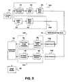
- FIG. 1is a block diagram showing an embodiment of the invention generally designated system 100 .
- System 100includes a waveform generator 110 that produces waveforms having a plurality of pulses. These pulses are optionally of differing or multiple frequencies.
- the output of waveform generator 110is coupled to a broad-beam transmitter 115 .
- Broad-beam transmitter 115splits the input waveform into multiple channels, amplifies the signal, and/or applies the delays required to form a broad-beam ultrasound wave.
- Broad-beam technologyreduces the number of transmitted pulses required to image an area and enables use of area-forming techniques in place of prior art beam-forming methods.
- broad-beam transmitter 115is replaced by a prior art beam transmitter.
- the output of broad-beam transmitter 115is coupled through a multi-channel transmit/receive switch 120 and used to drive an ultrasound transducer 125 .
- Ultrasound transducer 125sends ultrasound pulses 127 into a media of interest 130 . These ultrasound pulses 127 are modified through attenuation, scattering, reflection, harmonic generation, or the like. Returning echoes are received by transducer elements 128 .
- Transducer elements 128which are used to detect echoes, may be a part of ultrasound transducer 125 , used to generate ultrasound pulses 127 .
- the detected signalsinclude ultrasound with frequencies near the original transmitting frequency as well as with other harmonic frequencies.
- Each of transducer elements 128converts the received ultrasound pulses into electrical signals and couples these electrical signals to a distinct data channel 133 .
- pulsesare coupled to multi-channel transmit/receive switch 120 from distinct data channels 133 .
- Transmit/receive switch 120directs the electrical signals to a multi-channel analog amplifier 135 .
- Analog amplifier 135amplifies the signals and couples them to a mixer 140 for demodulation.
- Mixer 140can be an analog mixer, a multi-channel mixer, a phase modulator, a time signal multiplier and/or any other signal modulator known in the art.
- the demodulated signalsare made up of in-phase and quadrature (I/Q) components.
- Each distinct data channel 133is independently coupled through a filter 142 .
- filter 142includes a multi-channel band-pass filter that selectively impedes specific frequency ranges.
- the resulting signalsare digitized using a multi-channel A/D (analog to digital) converter 145 and are stored in an I/Q data buffer 150 .
- I/Q data buffer 150is multi-channel and can optionally be programmed to individually sum digitized signals received from each distinct data channel 133 .
- I/Q data buffer 150makes the stored data available to a preprocessing module 160 .
- a digital mixer 140 and/or digital filter 142are optionally placed after A/D converter 145 .
- An embodiment of preprocessing module 160includes a plurality of frequency band preprocessors 162 A-Z. These labels are arbitrary designations and not intended to limit the number of frequency band preprocessors 162 to twenty-six.
- Each frequency band preprocessor 162can process multiple data sets, from several or all of the distinct data channels 133 , stored in I/Q data buffer 150 .
- the frequency band preprocessorsare optionally differentiated by one or more characteristics. These differentiating characteristics include, for example, the processing frequency range (frequency band), specific encoding within the processed signal, the mode of processing preformed, or the like. Signals, resulting from one or more transmit/receive cycles, are optionally combined, filtered, decoded, and/or modulated, prior to image formation.
- each frequency band preprocessor 162 A-Z within preprocessing module 160can access all or part of the data within I/Q data buffer 150 .
- the frequency band preprocessors 162 A-Zmay each take selected data and process it in parallel such that all of the data passed by band-pass filter 142 is optionally processed by at least one frequency band preprocessor 162 A-Z.
- the preprocessed, multi-band, multi-channel signalsare optionally stored in multi-channel data buffer 165 and made available to a series of area-formers 172 within an area-forming module 170 .
- area-formers 172are individually designated 172 A-Z. These labels are arbitrary designations and not intended to limit the number of area-former 172 A-Z to twenty-six.
- Embodiments of area-forming module 170processes data stored in multi-channel data buffer 165 , or delivered directly from preprocessing module 160 .
- the processing performed by area-forming module 170includes calculating positional information regarding the source of signals within the media of interest 130 .
- Each of area-former 172 A-Zis capable of forming positional information covering an area using broad-beam technology, rather than just positional information along a line. Because preprocessing module 160 preprocesses the data, each of area-formers 172 optionally operates on a data set restricted to a specific criterion or processed to accentuate a specific aspect of the data. For example, in one embodiment area-former 172 A receives data preprocessed to identify moving components within media of interest 130 .
- Area-former 172 Amay operate on Doppler components of the total signal received by preprocessing module 160 .
- area-former 172 Bis disposed to process data combined after processing by frequency band preprocessors 162 A and 162 B, each of which preprocesses data with a specific encoding.
- frequency band preprocessors 162 A and 162 Beach of which preprocesses data with a specific encoding.
- each area-former 172 A-ZWhen input data is processed in parallel, each area-former 172 A-Z generates output data with the same time zero and temporal characteristics and the output data is temporally synchronized. Because preprocessing module 160 optionally reduces the total amount of data, area-forming module 170 may operate on only part of the data received by preprocessing module 160 and calculations may, thus, be performed more rapidly.
- Data prepared by preprocessing module 160are parallel processed by area-forming module 170 .
- the parallel aspect of the processingeliminates temporal delays between the outputs of the area-forming module 170 and allows different types of imaging modes to be simultaneously executed. For example, data accentuating motion can be processed in one imaging mode at the same time that data representing static structures is processed in another imaging mode.
- output of area-forming module 170is combined, or further processed, in a post-processor system 180 . Since the outputs of area-forming module 170 can be based on signals recorded at substantially the same time, the output data, which can result from several imaging modes, are combined without introducing temporal jitter.
- post-processor system 180also combines data from multiple broad-beam zones and prepares a single data set for delivery to an image scan converter 190 for output on an optional image display 192 .
- FIG. 2is a flow diagram showing steps of an embodiment of the invention utilizing the system illustrated by FIG. 1 .
- waveform generator 110is used to produce a waveform having a series of pulses. These pulses are grouped as singlets, pairs, or larger combinations of pulses.
- the waveform generated in waveform generation step 210optionally includes a plurality of characteristics such as frequencies, amplitudes, pulse widths, phases, or variation thereof. These characteristics are optionally used to encode the waveform.
- FIG. 3illustrates the waveform including a series of pulse pairs having opposite phase.
- broad-beam transmitter 115processes the waveform generated by waveform generator 110 .
- the processing by broad-beam transmitter 115includes amplifying the waveform, separating the waveform among distinct data channels 133 , applying delays and weightings to each distinct data channel 133 , and the like.
- Broad-beam generation step 215further effectuates coupling the processed waveform within each distinct data channel 133 to multi-channel transmit/receive switch 120 and to multi-element ultrasound transducer 125 .
- each element of ultrasound transducer 125emits ultrasound pulses 127 using the processed waveforms. Since the present invention optionally includes broad-beam technology, the number of pulses required to cover the imaging area can be significantly fewer than the number required to cover a similar area using conventional beamforming methods known in the art.
- ultrasound pulses 127propagate through media of interest 130 . Variations in media of interest 130 cause echoes to be generated and ultrasound pulses 127 to be altered.
- returning ultrasound signalsare received by ultrasound transducer 125 using transducer elements 128 . Transducer elements 128 receive the returning ultrasound signals at the frequency near or at the frequencies of ultrasound pulses 127 and/or at harmonics thereof.
- Each receivergenerates signals in at least one of distinct data channel 133 and the signals of each distinct data channel 133 are coupled through transmit/receive switch 120 to analog amplifier 135 .
- From echo receiving step 230 through a post-processing step 275all operations are optionally performed on distinct data sets, such as set distinguished by different analysis modes, in parallel.
- An amplification step 235uses a low-noise analog amplifier 135 to amplify distinct data channel 133 signals.
- each channelis processed by mixer 140 that demodulates the signals.
- FIG. 4Aillustrates an example of a resulting demodulated signal spectrum from a single channel associated with a single receiver. Signal components can be found near the frequency (f 0 ) at which the ultrasound was transmitted and at harmonics of the transmitted frequency (2f 0 , 3f 0 , or the like).
- mixer 140demodulates the components of the signal at the fundamental frequency (f 0 ) to a base-band frequency (f b ) and demodulates the 2 nd harmonic components of the signal to a new frequency (f b +f 0 ).
- f bbase-band frequency
- FIG. 4 Beach signal is optionally coupled through filter 142 .
- Filter 142applies a high-pass, low-pass, or band-pass filter to the signal. The type of filtering is selected as a function of the expected use of the signal.
- A/D conversion step 250the signal in each distinct data channel 133 is converted from the analog to the digital domain by A/D converter 145 .
- A/D conversion step 250occurs prior to demodulation step 240 or filtering step 245 .
- a data storage step 255the digitized data from each channel is stored in I/Q data buffer 150 .
- I/Q buffer 150optionally sums the digital signals resulting from a plurality of pulses. The summed, “raw,” data is sampled at the output of the I/Q data buffer 150 . Under selected summation and phase conditions, the summation process results in an average approaching zero for some components of the signals.
- preprocessing module 160reads data from I/Q data buffer 150 and processes it using one or more of frequency band preprocessors 162 A-Z
- Each frequency band preprocessor 162 A-Zcan access all of the data available in I/Q data buffer 150 . However, depending on the type of imaging mode desired, each frequency band preprocessor 162 A-Z can also be operated to process only a segment of the data. In various aspects of the invention, these segments are divided by transducer channel, frequency range, or encoding. In various embodiments, frequency band preprocessors 162 A-Z apply a variety of processing routines to the data.
- preprocessing module 160processes the data stored in I/Q data buffer 150 in multiple modes, in multiple frequency bands, with multiple encodings, and/or in multiple independent data channels. Since preprocessing module 160 consists of multiple independent frequency band preprocessors 162 A-Z, processing can occur in parallel.
- signalsare processed by frequency band pre-processors 162 A-Z as a function of encoding included within the signal. For example, if waveform generator 110 produces pulses at two or more distinct frequencies, the returned (encoded) ultrasound echoes can be differentiated (decoded) by their frequency. This ability to differentiate allows pulses to be sent into the material under investigation at a rate faster than un-encoded pulses, since a second set of pulses can be sent before the first is received. Using this encoding the pulse transmit rate and the collection of data is not limited by the roundtrip time of a pulse. The pulse roundtrip time is the time between transmission of a pulse and the detection of all resulting echoes. Frequency band preprocessors 162 A-Z can be individually arranged to select and process signals resulting from one or more of distinct frequency bands.
- datais optionally stored in multi-channel data buffer 165 in a data storing step 265 .
- This stepenables further data manipulation, such as averaging and synchronization between preprocessing module 160 and area-forming module 170 . If the product of the number of preprocessing modes, frequency bands, and data channels is larger than the number of frequency band pre-processors then some of the channels can be preprocessed in parallel and the results are stored in multi-channel data buffer 165 . Following this preprocessing process, another set of channels is optionally preprocessed and stored. The preprocessing process can be repeated until all channels have been preprocessed and stored.
- the use of multi-channel data buffer 165further enables the implementation of a larger number of parallel preprocessing modes, frequency bands, encoding, and the like.
- preprocessed datais used to perform parallel area-forming calculations using area-forming module 170 .
- Area-forming module 170includes a plurality of area-former 172 A-Z, Each area-former 172 A-Z can be enabled to identify locations of echo sources from data generated by an individual frequency band preprocessor 162 A-Z,
- area-former 172 Ais configured to process data preprocessed by frequency band preprocessor 162 A.
- area-former 172 Ais configured to process data combined in multi-channel data buffer 165 after parts of the data are separately preprocessed by frequency band preprocessor 162 B and frequency band preprocessor 162 A. Preprocessing the data potentially reduces noise, undesirable signal components, and the total amount of data within each data channel.
- area-former 172 A-Zwithin area-forming module 170 enables parallel processing of data associated with multiple imaging modes.
- area-former 172 Ais configured to process data associated with moving echo sources and area-formi er 172 B is configured to process data associated with static echo sources.
- area-former 172 Ais configured to process data with encoding type A and area-former 172 B is configured to process data with encoding type B, where encoding types A and B are any two distinguishable encoding schemes.
- post-processing step 275the output of area-forming module 170 is post-processed by post-processing system 180 .
- Post-processingcan include one or more elements such as encoding of data generated using different modes, sum and difference calculations between data generated using different modes, calculation of differences among data recorded at different times, differential and integral calculations, or the like.
- Post-processing system 180can also combine data derived from multiple transmit zones to produce data sets covering an expanded area. Post-processing generates at least data representing some attribute of the signal as a function of a coordinate system.
- an imageis prepared using image scan converter 190 .
- the imageoptionally includes motion video and/or false color representations of the encoding developed in post-processing step 275 .
- velocities of detected materialsare calculated and colors are chosen so as to visually convey the range and distribution of velocities.
- static components of the material of interestare shown using a color scheme designed to show material ultrasound reflectivity.
- the image prepared in image scan conversion step 280is displayed using image display 192 .
- the final imagesare displayed with little or no time delay or time lag between various components of the image that result from different imaging mode or frequency bands.
- more than one imaging modeis optionally performed on a single set of data produced from a single set of transmitted ultrasound pulses.
- a single set of ultrasound pulsesare used in parallel to generate echo location data based on multiple analysis modes.
- parallel multi-mode imagingcreates a visibly temporally synchronized image, thereby eliminating time jitter (temporal anomalies) associated with prior art methods of serial generation of echo data in multi-rode imaging.
- Multi-band preprocessing and area-formingenables the separation of signals based on encoding characteristics. For example, images, or other echo location data, produced from separate frequency bands can be formed in parallel and compounded together to decrease speckle noise without reduction of frame rate.
- FIG. 5is a block diagram showing an embodiment of the invention wherein harmonic signals for 2D imaging and fundamental signals for color Doppler imaging are produced and processed in parallel.
- This embodimentexecutes the two different data processing modes at the same time.
- one of the modesis designed to perform high-resolution 2D harmonic tissue imaging, while the other mode is designed to perform color Doppler flow imaging. Both modes use the same set of data that are produced from a series of pulse firings and collected at I/Q data buffer 150 .
- Alternative embodimentsoptionally include more than two different analysis modes executed in parallel.
- frequency band preprocessor 162 AIn the 2D harmonic tissue imaging mode, data is copied from I/Q buffer 150 to frequency band preprocessor 162 A.
- frequency band preprocessor 162 Ais used to process harmonic signals to produce a high resolution 2D tissue image.
- Frequency band preprocessor 162 Ais configured to include multi-pulse averager 510 , digital mixer 520 , and base-band filter 530 .
- the results of the preprocessingare optionally stored in multi-channel data buffer 165 and coupled to area-former 172 A to reconstruct echo location data (image).
- the echo location data (image)is coupled to post-processor 182 A.
- post-processor 182 Aincludes a magnitude detector 560 and 2D image processor 570 .
- frequency band preprocessor 162 BIn the Doppler flow imaging mode, data is copied from I/Q buffer 150 to frequency band preprocessor 162 B. In this embodiment, this data is the same data copied from I/Q buffer 150 for use in a parallel 2D harmonic tissue imaging mode.
- frequency band preprocessor 162 BIn the Doppler flow imaging mode, frequency band preprocessor 162 B is configured to include a clutter filter 540 and a base-band filter 550 . Using these elements, frequency band preprocessor 162 B processes the fundamental frequency signal to detect moving targets within media of interest 130 .
- post-processor 182 BAfter optional storage in multi-channel data buffer 165 and processing by area-former 172 B, the re-constructed echo location data is coupled to post-processor 182 B, which includes a Doppler flow estimator 580 and a color flow image processor 590 .
- Image scan converter 190combines the echo location data generated using both processing modes and converts the combined data into an appropriate display format to form the final image. The final image
- preprocessor 162 Aincludes multi-pulse averager 510 , digital mixer 520 , and base-band filter 530 in one instance of an embodiment, in a subsequent instance of the same embodiment preprocessor 162 A may be reconfigured via software to include instead clutter filter 540 and base-band filter 550 .
- Post-processor 182 Ais optionally configurable through software in an analogous manner.
- FIG. 6includes two flowcharts showing processes enabling two different imaging modes that can be executed in parallel utilizing the elements shown in FIG. 5 .
- FIG. 6Ashows steps involved in a method of the invention wherein harmonic signals are processed for 2D imaging.
- FIG. 6Bshows steps involved in a method of the invention wherein fundamental signals are processed for Doppler imaging. Both flowcharts start from step 255 and conclude at step 280 of FIG. 2 .
- data preprocessing step 260includes a data averaging step 610 , a digital modulation step 620 , and a base-band filtering step 630 .
- data averaging step 610multi-pulse averager 510 ( FIG. 5 ) reduces or eliminates fundamental frequency components by averaging multiple received signals generated using multiple pairs of phase-inverted transmitting pulses. Since the 2 nd harmonic component of the received signals from these phase-inverted pulse sequence are in-phase, the signal-to-noise ratio of the 2 nd harmonic component is enhanced by the averaging process. An illustration of resulting signals is shown in FIG. 7 A. Signals at the fundamental frequency are essentially cancelled and the 2 nd harmonic signals are enhanced.
- the signal averagesimply serves to improve signal-to-noise ratio.
- digital demodulation step 620the digital mixer 520 demodulates the 2 nd harmonic component down to base-band frequency. Possible resulting signals are illustrated in FIG. 7 B.
- base-band filtering step 630base-band filter 530 is used to filter out any residual fundamental frequency component and other noise outside the base-band, while preserving the demodulated 2 nd harmonic signal.
- the dataare optionally stored, in a data storing step 265 , in multi-channel data buffer 165 .
- the pre-processed 2 nd harmonic componentsare coupled to area-former 172 A and echo location data is re-constructed for 2D tissue image.
- post-processing step 275includes a signal magnitude detection step 640 and a 2D image processing step 650 .
- Magnitude detection step 640includes I/Q signal-to-magnitude conversion and log-compression.
- 2D image processing step 650optionally includes operations such as adjustment of gain and dynamic range, spatial and/or temporal filtering, and the like.
- preprocessing step 260includes a clutter filtering step 660 and a base-band filtering step 670 .
- clutter filtering step 660clutter filter 540 is applied to the same multiple signals collected for harmonic tissue imaging to remove signals resulting from stationary and slow-moving sources within the media of interest 130 .
- base-band filtering step 670base-band filter 550 is used to extract the clutter filtered fundamental frequency component and remove any noise outside base-band.
- Preprocess data step 260is followed by optional store data step 265 and area-forming step 270 .
- a post-processing step 275includes a Doppler parameter estimation step 680 and a Doppler parameter post-processing step 690 .
- Doppler parameter estimation step 680Doppler flow estimator 580 calculates flow parameters such as Doppler velocity, Doppler velocity variance, Doppler energy, and the like. These calculations are optionally accomplished using auto-correlation methods known in the art.
- color flow image processor 590can use thresholds, noise reduction, smoothing, color coding and/or other image processing techniques to generate a color image conveying information of the Doppler parameters of interest.
- FIGS. 6A and 6Bare optionally performed in parallel.
- the results of both processesare combined in a single image data set in image scan conversion step 280 (FIG. 2 ).
- This single image data setis displayed in display step 285 using image display 192 . Since both imaging modes are executed in parallel and use the same set of received data the outputs are generated more quickly than serial execution and the images produced using each imaging mode are temporally synchronized with each other. Quicker image generation enables a higher frame rate.
- the synchronization of data collection for multiple imaging modescan eliminate or reduce temporal anomalies within a resulting composite image. Encoded data arising from multiple transmitted pulses are optionally added together to improve signal-to-noise ratios.
- Steps 260 through 275optionally include additional and alternative imaging modes such as fundamental imaging, color Doppler imaging, harmonic imaging, spectral Doppler imaging, and/or any other ultrasound imaging mode.
- additional and alternative imaging modessuch as fundamental imaging, color Doppler imaging, harmonic imaging, spectral Doppler imaging, and/or any other ultrasound imaging mode.
- Combinations of three or more parallel modesare also possible in alternative embodiments.
- one set of three parallel modesincludes harmonic tissue imaging, color Doppler imaging, and spectral Doppler imaging.
- another set of three parallel modesincludes harmonic tissue imaging, Doppler tissue imaging and color Doppler imaging.
- each zonecan be processed independently and an image of the combined zones can be constructed by image scan converter 190 .
- a set of N pulsesis used to generate data using parallel processing.
- K zonesa total of K*N pulses are required to form a complete image.
- the minimum value of Nis two and for other imaging modes the minimum value of N is one.
- Increasing the number of processing modesdoes not necessarily increase the number of required pulses.
- minimizing power consumptionextends the lifetime of limited power sources, such as batteries, and enables the use of battery powered, single or multi-mode, instruments with increased operating times.
- the parallel processing architecture described in this inventionresult in very fast data processing speeds.
- the pre-processing of raw I/Q dataoptimizes the input signal and improves signal to noise ratios prior to area formation. This optimized input signal improves the quality of area formation and precision of the resulting image data.
- preprocessing module 160 and area-forming module 170can be used for the processing of ultrasound data obtained through alternative means.
- area formers 172are replaced by alternative echo-forming systems, such as series of parallel multi-line beamformers, individual examples of which are known in the art. Echo-forming systems include beam-forming systems, area-forming systems, volume-forming systems, and multidimensional-forming systems.
- the ultrasound system of the present inventionmay be used to image a wide range of materials.
Landscapes
- Physics & Mathematics (AREA)
- General Physics & Mathematics (AREA)
- Engineering & Computer Science (AREA)
- Acoustics & Sound (AREA)
- Immunology (AREA)
- Health & Medical Sciences (AREA)
- General Health & Medical Sciences (AREA)
- Analytical Chemistry (AREA)
- Chemical & Material Sciences (AREA)
- Pathology (AREA)
- Life Sciences & Earth Sciences (AREA)
- Biochemistry (AREA)
- Radar, Positioning & Navigation (AREA)
- Remote Sensing (AREA)
- Computer Networks & Wireless Communication (AREA)
- Ultra Sonic Daignosis Equipment (AREA)
- Investigating Or Analyzing Materials By The Use Of Ultrasonic Waves (AREA)
- Organic Low-Molecular-Weight Compounds And Preparation Thereof (AREA)
Abstract
Description
Claims (19)
Priority Applications (15)
| Application Number | Priority Date | Filing Date | Title |
|---|---|---|---|
| US10/039,862US6896658B2 (en) | 2001-10-20 | 2001-10-20 | Simultaneous multi-mode and multi-band ultrasonic imaging |
| US10/211,391US6685645B1 (en) | 2001-10-20 | 2002-08-01 | Broad-beam imaging |
| DE10248747.2ADE10248747B4 (en) | 2001-10-20 | 2002-10-18 | Wide-ray picture |
| JP2002304291AJP2003180687A (en) | 2001-10-20 | 2002-10-18 | Simultaneous multi-mode and multi-band ultrasonic imaging |
| DE10248745.6ADE10248745B4 (en) | 2001-10-20 | 2002-10-18 | Method of using ultrasound to analyze media of interest and ultrasound analysis system |
| JP2002304295AJP4874497B2 (en) | 2001-10-20 | 2002-10-18 | Wide beam imaging |
| US10/759,558US7238157B2 (en) | 1999-08-20 | 2004-01-16 | Broad-beam imaging methods |
| US11/043,632US7682309B2 (en) | 2001-10-20 | 2005-01-25 | Ultrasound system for generating a single set of ultrasound pulse firings |
| US11/592,702US8679018B2 (en) | 1999-08-20 | 2006-11-03 | Broad-beam imaging |
| US12/684,084US8226561B2 (en) | 1999-08-20 | 2010-01-07 | Ultrasound imaging system |
| US12/684,086US8764661B2 (en) | 1999-08-20 | 2010-01-07 | Echolocation data generation |
| JP2010019579AJP5489758B2 (en) | 2001-10-20 | 2010-01-29 | Wide beam imaging |
| JP2012219778AJP5490198B2 (en) | 2001-10-20 | 2012-10-01 | Wide beam imaging |
| US14/270,230US20150087983A1 (en) | 1999-08-20 | 2014-05-05 | Echolocation Data Generation |
| US14/687,801US20160011498A1 (en) | 1999-08-20 | 2015-04-15 | Echolocation data generation |
Applications Claiming Priority (1)
| Application Number | Priority Date | Filing Date | Title |
|---|---|---|---|
| US10/039,862US6896658B2 (en) | 2001-10-20 | 2001-10-20 | Simultaneous multi-mode and multi-band ultrasonic imaging |
Related Parent Applications (1)
| Application Number | Title | Priority Date | Filing Date |
|---|---|---|---|
| US10/039,910Continuation-In-PartUS6936008B2 (en) | 1999-08-20 | 2001-10-20 | Ultrasound system with cableless coupling assembly |
Related Child Applications (3)
| Application Number | Title | Priority Date | Filing Date |
|---|---|---|---|
| US10/039,922Continuation-In-PartUS6773399B2 (en) | 1999-08-20 | 2001-10-20 | Block-switching in ultrasound imaging |
| US10/759,558Continuation-In-PartUS7238157B2 (en) | 1999-08-20 | 2004-01-16 | Broad-beam imaging methods |
| US11/043,632ContinuationUS7682309B2 (en) | 2001-10-20 | 2005-01-25 | Ultrasound system for generating a single set of ultrasound pulse firings |
Publications (2)
| Publication Number | Publication Date |
|---|---|
| US20030078497A1 US20030078497A1 (en) | 2003-04-24 |
| US6896658B2true US6896658B2 (en) | 2005-05-24 |
Family
ID=21907718
Family Applications (2)
| Application Number | Title | Priority Date | Filing Date |
|---|---|---|---|
| US10/039,862Expired - LifetimeUS6896658B2 (en) | 1999-08-20 | 2001-10-20 | Simultaneous multi-mode and multi-band ultrasonic imaging |
| US11/043,632Expired - LifetimeUS7682309B2 (en) | 2001-10-20 | 2005-01-25 | Ultrasound system for generating a single set of ultrasound pulse firings |
Family Applications After (1)
| Application Number | Title | Priority Date | Filing Date |
|---|---|---|---|
| US11/043,632Expired - LifetimeUS7682309B2 (en) | 2001-10-20 | 2005-01-25 | Ultrasound system for generating a single set of ultrasound pulse firings |
Country Status (3)
| Country | Link |
|---|---|
| US (2) | US6896658B2 (en) |
| JP (1) | JP2003180687A (en) |
| DE (1) | DE10248745B4 (en) |
Cited By (30)
| Publication number | Priority date | Publication date | Assignee | Title |
|---|---|---|---|---|
| US20030013966A1 (en)* | 1996-06-28 | 2003-01-16 | Sonosite, Inc. | Balance body ultrasound system |
| US20030195418A1 (en)* | 1996-06-28 | 2003-10-16 | Sonosite, Inc. | Balance body ultrasound system |
| US20040133110A1 (en)* | 2002-02-01 | 2004-07-08 | Sonosite, Inc. | CW beam former in an ASIC |
| US20040138564A1 (en)* | 1996-06-28 | 2004-07-15 | Sonosite, Inc. | Ultrasonic signal processor for a hand held ultrasonic diagnostic instrument |
| US20040152982A1 (en)* | 2002-03-29 | 2004-08-05 | Sonosite, Inc. | Modular apparatus for diagnostic ultrasound |
| US20040150963A1 (en)* | 2003-01-31 | 2004-08-05 | Sonosite, Inc. | System for use with a modular apparatus for diagnostic ultrasound |
| US20050131294A1 (en)* | 2001-10-20 | 2005-06-16 | Zonare Medical Systems, Inc. | Ultrasound system for generating a single set of ultrasound pulse firings |
| US20060036178A1 (en)* | 1999-08-20 | 2006-02-16 | Umit Tarakci | Cableless coupling methods for ultrasound |
| US20060173308A1 (en)* | 2003-06-03 | 2006-08-03 | Akira Sasaki | Ultrasonograph |
| US20070016072A1 (en)* | 2005-05-06 | 2007-01-18 | Sorin Grunwald | Endovenous access and guidance system utilizing non-image based ultrasound |
| US20070049822A1 (en)* | 2005-08-31 | 2007-03-01 | Sonosite, Inc. | Medical device guide locator |
| US20070093715A1 (en)* | 2005-10-24 | 2007-04-26 | Sonosite, Inc. | Array interconnect for improved directivity |
| US20070213615A1 (en)* | 1999-08-20 | 2007-09-13 | Mclaughlin Glen | Broad-beam imaging |
| US20080316861A1 (en)* | 2001-10-20 | 2008-12-25 | Xufeng Xi | Block-switching in ultrasound imaging |
| US20090005675A1 (en)* | 2005-05-06 | 2009-01-01 | Sorin Grunwald | Apparatus and Method for Endovascular Device Guiding and Positioning Using Physiological Parameters |
| US20090118612A1 (en)* | 2005-05-06 | 2009-05-07 | Sorin Grunwald | Apparatus and Method for Vascular Access |
| US20090171216A1 (en)* | 2007-12-27 | 2009-07-02 | Alain Sadaka | Connections For Ultrasound Transducers |
| US7643040B1 (en) | 2004-04-08 | 2010-01-05 | Sonosite, Inc. | System and method for enhancing gray scale output on a color display |
| US7686766B2 (en) | 2001-04-19 | 2010-03-30 | Sonosite, Inc. | Medical diagnostic ultrasound instrument with ECG module, authorization mechanism and methods of use |
| US20100217126A1 (en)* | 2009-02-25 | 2010-08-26 | Tsutomu Yawata | Ultrasonic diagnostic apparatus, method of displaying ultrasonic images and program |
| US8066642B1 (en) | 2005-05-03 | 2011-11-29 | Sonosite, Inc. | Systems and methods for ultrasound beam forming data control |
| US8965490B2 (en) | 2012-05-07 | 2015-02-24 | Vasonova, Inc. | Systems and methods for detection of the superior vena cava area |
| US9117439B2 (en) | 2008-03-13 | 2015-08-25 | Supersonic Imagine | Method and apparatus for ultrasound synthetic imagining |
| US9119551B2 (en) | 2010-11-08 | 2015-09-01 | Vasonova, Inc. | Endovascular navigation system and method |
| US9864485B2 (en) | 2014-03-21 | 2018-01-09 | Biolase, Inc. | Dental laser interface system and method |
| US10154826B2 (en) | 2013-07-17 | 2018-12-18 | Tissue Differentiation Intelligence, Llc | Device and method for identifying anatomical structures |
| US10201326B2 (en) | 2013-07-02 | 2019-02-12 | Samsung Electronics Co., Ltd. | Ultrasonic diagnostic apparatus and method of operating the same |
| US10716536B2 (en) | 2013-07-17 | 2020-07-21 | Tissue Differentiation Intelligence, Llc | Identifying anatomical structures |
| US11701086B1 (en) | 2016-06-21 | 2023-07-18 | Tissue Differentiation Intelligence, Llc | Methods and systems for improved nerve detection |
| US11986341B1 (en) | 2016-05-26 | 2024-05-21 | Tissue Differentiation Intelligence, Llc | Methods for accessing spinal column using B-mode imaging to determine a trajectory without penetrating the the patient's anatomy |
Families Citing this family (20)
| Publication number | Priority date | Publication date | Assignee | Title |
|---|---|---|---|---|
| US8658453B2 (en)* | 2004-09-15 | 2014-02-25 | Sonetics Ultrasound, Inc. | Capacitive micromachined ultrasonic transducer |
| US7888709B2 (en)* | 2004-09-15 | 2011-02-15 | Sonetics Ultrasound, Inc. | Capacitive micromachined ultrasonic transducer and manufacturing method |
| US20080015436A1 (en)* | 2006-07-13 | 2008-01-17 | Misonix, Incorporated | High intensity focused ultrasound method and associated apparatus |
| US8690782B2 (en)* | 2007-07-12 | 2014-04-08 | Siemens Medical Solutions Usa, Inc. | System for generating multiple beams from a single receive event |
| CN102665569B (en) | 2009-10-12 | 2015-05-13 | 硅谷医疗器械有限公司 | Intravascular ultrasound system for co-registered imaging |
| JP5760994B2 (en)* | 2011-11-30 | 2015-08-12 | コニカミノルタ株式会社 | Ultrasound diagnostic imaging equipment |
| US9693754B2 (en) | 2013-05-15 | 2017-07-04 | Acist Medical Systems, Inc. | Imaging processing systems and methods |
| JP6353038B2 (en) | 2013-10-07 | 2018-07-04 | アシスト・メディカル・システムズ,インコーポレイテッド | Signal processing for intravascular imaging |
| WO2017027789A1 (en) | 2015-08-12 | 2017-02-16 | Sonectics Ultrasound, Inc. | Method and system for measuring pressure using ultrasound |
| US10653393B2 (en) | 2015-10-08 | 2020-05-19 | Acist Medical Systems, Inc. | Intravascular ultrasound imaging with frequency selective imaging methods and systems |
| US10909661B2 (en) | 2015-10-08 | 2021-02-02 | Acist Medical Systems, Inc. | Systems and methods to reduce near-field artifacts |
| US11369337B2 (en) | 2015-12-11 | 2022-06-28 | Acist Medical Systems, Inc. | Detection of disturbed blood flow |
| WO2017117389A1 (en) | 2015-12-31 | 2017-07-06 | Acist Medical Systems, Inc. | Semi-automated image segmentation system and method |
| US10489919B2 (en) | 2016-05-16 | 2019-11-26 | Acist Medical Systems, Inc. | Motion-based image segmentation systems and methods |
| CN107561157B (en)* | 2016-06-30 | 2023-08-04 | 重庆医科大学 | Water quality detector and method thereof |
| DE112018003501T5 (en)* | 2017-07-09 | 2020-04-23 | The Board Of Trustees Of The Leland Stanford Junior University | ULTRASOUND IMAGING WITH SPECTRAL COMPOUNDING FOR SPECKLE REDUCTION |
| US11372092B2 (en)* | 2019-01-04 | 2022-06-28 | Shenzhen Mindray Bio-Medical Electronics Co., Ltd. | Hybrid ultrasound transmitter |
| US11024034B2 (en) | 2019-07-02 | 2021-06-01 | Acist Medical Systems, Inc. | Image segmentation confidence determination |
| CN113534088A (en)* | 2021-07-02 | 2021-10-22 | 中国船舶重工集团公司第七二四研究所 | A Design Method for Multi-level Parallel Software Real-time Processing of Radar Signals |
| CN117322905A (en)* | 2022-06-27 | 2024-01-02 | 深圳开立生物医疗科技股份有限公司 | Ultrasonic contrast imaging method and device, ultrasonic equipment and storage medium |
Citations (41)
| Publication number | Priority date | Publication date | Assignee | Title |
|---|---|---|---|---|
| US4398540A (en) | 1979-11-05 | 1983-08-16 | Tokyo Shibaura Denki Kabushiki Kaisha | Compound mode ultrasound diagnosis apparatus |
| US4409982A (en) | 1980-10-20 | 1983-10-18 | Picker Corporation | Ultrasonic step scanning utilizing curvilinear transducer array |
| US4803990A (en) | 1985-12-03 | 1989-02-14 | U.S. Philips Corporation | Examining moving objects by ultrasound echograpy |
| US4853904A (en) | 1986-09-19 | 1989-08-01 | U.S. Philips Corporation | Apparatus for examining a moving object by means of ultrasound echography |
| US5119342A (en) | 1990-10-05 | 1992-06-02 | Acoustic Imaging Technologies Corporation | Focused ultrasound imaging system and method |
| US5140558A (en) | 1988-08-29 | 1992-08-18 | Acoustic Imaging Technologies Corporation | Focused ultrasound imaging system and method |
| US5278757A (en) | 1991-11-15 | 1994-01-11 | The Trustees Of The University Of Pennsylvania | Synthetic aperture ultrasonic imaging system using a minimum or reduced redundancy phased array |
| US5291090A (en) | 1992-12-17 | 1994-03-01 | Hewlett-Packard Company | Curvilinear interleaved longitudinal-mode ultrasound transducers |
| US5295485A (en) | 1991-12-13 | 1994-03-22 | Hitachi, Ltd. | Ultrasonic diagnostic system |
| US5483963A (en) | 1994-07-22 | 1996-01-16 | Loral Infrared & Imaging Systems, Inc. | Two dimensional transducer integrated circuit |
| USRE35148E (en)* | 1983-05-16 | 1996-01-23 | Riverside Research Institute | Frequency diversity for image enhancement |
| US5505203A (en) | 1994-11-23 | 1996-04-09 | General Electric Company | Method and apparatus for automatic transducer selection in ultrasound imaging system |
| US5667373A (en) | 1994-08-05 | 1997-09-16 | Acuson Corporation | Method and apparatus for coherent image formation |
| US5722412A (en) | 1996-06-28 | 1998-03-03 | Advanced Technology Laboratories, Inc. | Hand held ultrasonic diagnostic instrument |
| US5740806A (en) | 1996-03-29 | 1998-04-21 | Siemens Medical Systems, Inc. | Dynamic receive aperture transducer for 1.5D imaging |
| US5793701A (en) | 1995-04-07 | 1998-08-11 | Acuson Corporation | Method and apparatus for coherent image formation |
| US5817024A (en) | 1996-06-28 | 1998-10-06 | Sonosight, Inc. | Hand held ultrasonic diagnostic instrument with digital beamformer |
| US5839442A (en) | 1995-06-29 | 1998-11-24 | Teratech Corporation | Portable ultrasound imaging system |
| US5893363A (en) | 1996-06-28 | 1999-04-13 | Sonosight, Inc. | Ultrasonic array transducer transceiver for a hand held ultrasonic diagnostic instrument |
| US5897501A (en) | 1997-05-07 | 1999-04-27 | General Electric Company | Imaging system with multiplexer for controlling a multi-row ultrasonic transducer array |
| US5905692A (en) | 1997-12-31 | 1999-05-18 | Analogic Corporation | Digital ultrasound beamformer |
| US5904652A (en) | 1995-06-29 | 1999-05-18 | Teratech Corporation | Ultrasound scan conversion with spatial dithering |
| US5908389A (en)* | 1996-09-27 | 1999-06-01 | Atl Ultrasound, Inc. | Ultrasonic diagnostic imaging of harmonic frequencies with speckle reduction processing |
| US5919138A (en) | 1997-08-22 | 1999-07-06 | Acuson Corporation | Ultrasound imaging system user interface |
| US5925967A (en) | 1998-02-13 | 1999-07-20 | Toda; Kohji | Ultrasonic switching device |
| US5964709A (en) | 1995-06-29 | 1999-10-12 | Teratech Corporation | Portable ultrasound imaging system |
| US5970025A (en) | 1998-06-10 | 1999-10-19 | Acuson Corporation | Ultrasound beamformation integrated circuit and method |
| US5973438A (en) | 1998-02-13 | 1999-10-26 | Toda; Kohji | Ultrasonic switching device |
| US6055861A (en) | 1993-06-02 | 2000-05-02 | Hewlett-Packard Company | Methods and apparatus for ultrasound imaging using combined scan patterns |
| US6063030A (en) | 1993-11-29 | 2000-05-16 | Adalberto Vara | PC based ultrasound device with virtual control user interface |
| US6089096A (en) | 1998-07-01 | 2000-07-18 | Aloka Co., Ltd. | Elevation focusing by beamformer channel sharing |
| US6113545A (en) | 1998-04-20 | 2000-09-05 | General Electric Company | Ultrasonic beamforming with improved signal-to-noise ratio using orthogonal complementary sets |
| US6126608A (en) | 1999-05-18 | 2000-10-03 | Pie Medical Equipment B.V. | Portable ultrasound diagnostic system with handsfree display |
| US6135961A (en) | 1996-06-28 | 2000-10-24 | Sonosite, Inc. | Ultrasonic signal processor for a hand held ultrasonic diagnostic instrument |
| US6139498A (en) | 1998-12-29 | 2000-10-31 | Ge Diasonics Israel, Ltd. | Ultrasound system performing simultaneous parallel computer instructions |
| US6174286B1 (en) | 1998-11-25 | 2001-01-16 | Acuson Corporation | Medical diagnostic ultrasound method and system for element switching |
| US6203498B1 (en) | 1996-06-28 | 2001-03-20 | Sonosite, Inc. | Ultrasonic imaging device with integral display |
| US6238346B1 (en) | 1999-06-25 | 2001-05-29 | Agilent Technologies, Inc. | System and method employing two dimensional ultrasound array for wide field of view imaging |
| US6251073B1 (en) | 1999-08-20 | 2001-06-26 | Novasonics, Inc. | Miniaturized ultrasound apparatus and method |
| US6514206B2 (en)* | 2001-03-09 | 2003-02-04 | Koninklijke Philips Electronics, N.V. | Simultaneous fundamental and harmonic ultrasonic imaging |
| US6695783B2 (en)* | 2000-12-22 | 2004-02-24 | Koninklijke Philips Electronics N.V. | Multiline ultrasound beamformers |
Family Cites Families (40)
| Publication number | Priority date | Publication date | Assignee | Title |
|---|---|---|---|---|
| US2961613A (en) | 1956-01-19 | 1960-11-22 | Hughes Aircraft Co | Linear frequency discriminator |
| US4044359A (en) | 1962-01-09 | 1977-08-23 | General Electric Company | Multiple intermediate frequency side-lobe canceller |
| DE2059507A1 (en) | 1970-12-03 | 1972-06-08 | Krupp Gmbh | Switching arrangement for damping a broadband basic noise level and interference signals superimposed on it |
| US3953822A (en) | 1973-10-15 | 1976-04-27 | Rca Corporation | Wave-energy imaging technique |
| US3952280A (en) | 1974-01-10 | 1976-04-20 | Esl Incorporated | Radiation monitoring of an object space with a clutter suppression technique |
| US4016750B1 (en) | 1975-11-06 | 1994-04-05 | Stanford Research Inst | Ultrasonic imaging method and apparatus |
| US4228804A (en) | 1978-02-28 | 1980-10-21 | Case Western Reserve University | Diagnostic ultrasonography utilizing frequency spectrum analysis presented in terms of B-scan color patterns or X-Y graph displays |
| US4295485A (en)* | 1978-04-26 | 1981-10-20 | Waterfield Engineering Limited | Diaphragm valve |
| JPS5571316A (en) | 1978-11-24 | 1980-05-29 | Hitachi Ltd | Recursive digital filter |
| US4412350A (en) | 1981-12-30 | 1983-10-25 | Bell Telephone Laboratories, Incorporated | Method and apparatus for distinguishing between minimum and non-minimum phase fades |
| US4471785A (en) | 1982-09-29 | 1984-09-18 | Sri International | Ultrasonic imaging system with correction for velocity inhomogeneity and multipath interference using an ultrasonic imaging array |
| US4926872A (en)* | 1988-03-28 | 1990-05-22 | Hewlett-Packard Company | Ultrasonic transducer system and method for the operation thereof |
| US5410516A (en) | 1988-09-01 | 1995-04-25 | Schering Aktiengesellschaft | Ultrasonic processes and circuits for performing them |
| DE4125109C2 (en)* | 1991-07-30 | 1994-10-20 | Gutehoffnungshuette Man | Continuous conveying ship unloader for bulk goods |
| US5255683A (en) | 1991-12-30 | 1993-10-26 | Sound Science Limited Partnership | Methods of and systems for examining tissue perfusion using ultrasonic contrast agents |
| US5369624A (en)* | 1993-03-26 | 1994-11-29 | Siemens Medical Systems, Inc. | Digital beamformer having multi-phase parallel processing |
| JPH078492A (en)* | 1993-06-28 | 1995-01-13 | Toshiba Corp | Ultrasonic diagnostic equipment |
| JP3465197B2 (en)* | 1993-09-14 | 2003-11-10 | 株式会社日立メディコ | Ultrasound diagnostic equipment |
| JPH0838473A (en)* | 1994-07-29 | 1996-02-13 | Hitachi Medical Corp | Ultrasonic diagnostic device |
| JP3625305B2 (en)* | 1994-12-28 | 2005-03-02 | 株式会社東芝 | Ultrasonic diagnostic equipment |
| US5608690A (en) | 1995-03-02 | 1997-03-04 | Acuson Corporation | Transmit beamformer with frequency dependent focus |
| US5617862A (en) | 1995-05-02 | 1997-04-08 | Acuson Corporation | Method and apparatus for beamformer system with variable aperture |
| ATE285711T1 (en)* | 1995-10-10 | 2005-01-15 | Advanced Tech Lab | ULTRASONIC IMAGING FOR DIAGNOSTICS USING CONTRAST AGENTS |
| US5793438A (en)* | 1995-11-13 | 1998-08-11 | Hyundai Electronics America | Electronic program guide with enhanced presentation |
| US5891038A (en)* | 1996-12-30 | 1999-04-06 | General Electric Company | Method, apparatus and applications for combining transmit wave functions to obtain synthetic waveform in ultrasonic imaging system |
| US6108572A (en)* | 1998-03-31 | 2000-08-22 | General Electric Company | Method and apparatus for harmonic imaging using multiple focal zones |
| US5980458A (en) | 1999-01-15 | 1999-11-09 | Hewlett-Packard Company | Data acquisition in ultrasonic imaging systems using multiple, parallel receive and transmit lines |
| JP2000217825A (en)* | 1999-01-28 | 2000-08-08 | Shimadzu Corp | Ultrasound diagnostic equipment |
| US6139501A (en)* | 1999-06-08 | 2000-10-31 | Atl Ultrasound, Inc. | Coincident tissue and motion ultrasonic diagnostic imaging |
| US6896658B2 (en)* | 2001-10-20 | 2005-05-24 | Zonare Medical Systems, Inc. | Simultaneous multi-mode and multi-band ultrasonic imaging |
| US6773399B2 (en) | 2001-10-20 | 2004-08-10 | Zonare Medical Systems, Inc. | Block-switching in ultrasound imaging |
| US6936008B2 (en) | 1999-08-20 | 2005-08-30 | Zonare Medical Systems, Inc. | Ultrasound system with cableless coupling assembly |
| JP5241980B2 (en)* | 2000-01-20 | 2013-07-17 | 株式会社東芝 | Ultrasonic diagnostic equipment |
| US6866631B2 (en) | 2001-05-31 | 2005-03-15 | Zonare Medical Systems, Inc. | System for phase inversion ultrasonic imaging |
| USD469877S1 (en) | 2001-08-31 | 2003-02-04 | Novasonics, Inc. | Handheld ultrasonic display device with cover |
| USD469539S1 (en) | 2001-08-31 | 2003-01-28 | Novasonics, Inc. | Handheld ultrasonic display device |
| USD467002S1 (en) | 2001-09-19 | 2002-12-10 | Novasonics, Inc. | Handheld ultrasonic transducer with curved bulb grip |
| USD462446S1 (en) | 2001-09-19 | 2002-09-03 | Novasonics, Inc. | Handheld ultrasonic transducer with bulb grip |
| USD461814S1 (en) | 2001-10-15 | 2002-08-20 | Novasonics, Inc. | Docking station |
| US6618206B2 (en) | 2001-10-20 | 2003-09-09 | Zonare Medical Systems, Inc. | System and method for acoustic imaging at two focal lengths with a single lens |
- 2001
- 2001-10-20USUS10/039,862patent/US6896658B2/ennot_activeExpired - Lifetime
- 2002
- 2002-10-18JPJP2002304291Apatent/JP2003180687A/enactivePending
- 2002-10-18DEDE10248745.6Apatent/DE10248745B4/ennot_activeExpired - Lifetime
- 2005
- 2005-01-25USUS11/043,632patent/US7682309B2/ennot_activeExpired - Lifetime
Patent Citations (42)
| Publication number | Priority date | Publication date | Assignee | Title |
|---|---|---|---|---|
| US4398540A (en) | 1979-11-05 | 1983-08-16 | Tokyo Shibaura Denki Kabushiki Kaisha | Compound mode ultrasound diagnosis apparatus |
| US4409982A (en) | 1980-10-20 | 1983-10-18 | Picker Corporation | Ultrasonic step scanning utilizing curvilinear transducer array |
| USRE35148F1 (en)* | 1983-05-16 | 1999-08-17 | Riverside Research Inst | Frequency diversity for image enhancement |
| USRE35148E (en)* | 1983-05-16 | 1996-01-23 | Riverside Research Institute | Frequency diversity for image enhancement |
| US4803990A (en) | 1985-12-03 | 1989-02-14 | U.S. Philips Corporation | Examining moving objects by ultrasound echograpy |
| US4853904A (en) | 1986-09-19 | 1989-08-01 | U.S. Philips Corporation | Apparatus for examining a moving object by means of ultrasound echography |
| US5140558A (en) | 1988-08-29 | 1992-08-18 | Acoustic Imaging Technologies Corporation | Focused ultrasound imaging system and method |
| US5119342A (en) | 1990-10-05 | 1992-06-02 | Acoustic Imaging Technologies Corporation | Focused ultrasound imaging system and method |
| US5278757A (en) | 1991-11-15 | 1994-01-11 | The Trustees Of The University Of Pennsylvania | Synthetic aperture ultrasonic imaging system using a minimum or reduced redundancy phased array |
| US5295485A (en) | 1991-12-13 | 1994-03-22 | Hitachi, Ltd. | Ultrasonic diagnostic system |
| US5291090A (en) | 1992-12-17 | 1994-03-01 | Hewlett-Packard Company | Curvilinear interleaved longitudinal-mode ultrasound transducers |
| US6055861A (en) | 1993-06-02 | 2000-05-02 | Hewlett-Packard Company | Methods and apparatus for ultrasound imaging using combined scan patterns |
| US6063030A (en) | 1993-11-29 | 2000-05-16 | Adalberto Vara | PC based ultrasound device with virtual control user interface |
| US5483963A (en) | 1994-07-22 | 1996-01-16 | Loral Infrared & Imaging Systems, Inc. | Two dimensional transducer integrated circuit |
| US5667373A (en) | 1994-08-05 | 1997-09-16 | Acuson Corporation | Method and apparatus for coherent image formation |
| US5505203A (en) | 1994-11-23 | 1996-04-09 | General Electric Company | Method and apparatus for automatic transducer selection in ultrasound imaging system |
| US5793701A (en) | 1995-04-07 | 1998-08-11 | Acuson Corporation | Method and apparatus for coherent image formation |
| US5839442A (en) | 1995-06-29 | 1998-11-24 | Teratech Corporation | Portable ultrasound imaging system |
| US5904652A (en) | 1995-06-29 | 1999-05-18 | Teratech Corporation | Ultrasound scan conversion with spatial dithering |
| US5964709A (en) | 1995-06-29 | 1999-10-12 | Teratech Corporation | Portable ultrasound imaging system |
| US5740806A (en) | 1996-03-29 | 1998-04-21 | Siemens Medical Systems, Inc. | Dynamic receive aperture transducer for 1.5D imaging |
| US5893363A (en) | 1996-06-28 | 1999-04-13 | Sonosight, Inc. | Ultrasonic array transducer transceiver for a hand held ultrasonic diagnostic instrument |
| US5722412A (en) | 1996-06-28 | 1998-03-03 | Advanced Technology Laboratories, Inc. | Hand held ultrasonic diagnostic instrument |
| US6203498B1 (en) | 1996-06-28 | 2001-03-20 | Sonosite, Inc. | Ultrasonic imaging device with integral display |
| US5817024A (en) | 1996-06-28 | 1998-10-06 | Sonosight, Inc. | Hand held ultrasonic diagnostic instrument with digital beamformer |
| US6135961A (en) | 1996-06-28 | 2000-10-24 | Sonosite, Inc. | Ultrasonic signal processor for a hand held ultrasonic diagnostic instrument |
| US5908389A (en)* | 1996-09-27 | 1999-06-01 | Atl Ultrasound, Inc. | Ultrasonic diagnostic imaging of harmonic frequencies with speckle reduction processing |
| US5897501A (en) | 1997-05-07 | 1999-04-27 | General Electric Company | Imaging system with multiplexer for controlling a multi-row ultrasonic transducer array |
| US5919138A (en) | 1997-08-22 | 1999-07-06 | Acuson Corporation | Ultrasound imaging system user interface |
| US5905692A (en) | 1997-12-31 | 1999-05-18 | Analogic Corporation | Digital ultrasound beamformer |
| US5973438A (en) | 1998-02-13 | 1999-10-26 | Toda; Kohji | Ultrasonic switching device |
| US5925967A (en) | 1998-02-13 | 1999-07-20 | Toda; Kohji | Ultrasonic switching device |
| US6113545A (en) | 1998-04-20 | 2000-09-05 | General Electric Company | Ultrasonic beamforming with improved signal-to-noise ratio using orthogonal complementary sets |
| US5970025A (en) | 1998-06-10 | 1999-10-19 | Acuson Corporation | Ultrasound beamformation integrated circuit and method |
| US6089096A (en) | 1998-07-01 | 2000-07-18 | Aloka Co., Ltd. | Elevation focusing by beamformer channel sharing |
| US6174286B1 (en) | 1998-11-25 | 2001-01-16 | Acuson Corporation | Medical diagnostic ultrasound method and system for element switching |
| US6139498A (en) | 1998-12-29 | 2000-10-31 | Ge Diasonics Israel, Ltd. | Ultrasound system performing simultaneous parallel computer instructions |
| US6126608A (en) | 1999-05-18 | 2000-10-03 | Pie Medical Equipment B.V. | Portable ultrasound diagnostic system with handsfree display |
| US6238346B1 (en) | 1999-06-25 | 2001-05-29 | Agilent Technologies, Inc. | System and method employing two dimensional ultrasound array for wide field of view imaging |
| US6251073B1 (en) | 1999-08-20 | 2001-06-26 | Novasonics, Inc. | Miniaturized ultrasound apparatus and method |
| US6695783B2 (en)* | 2000-12-22 | 2004-02-24 | Koninklijke Philips Electronics N.V. | Multiline ultrasound beamformers |
| US6514206B2 (en)* | 2001-03-09 | 2003-02-04 | Koninklijke Philips Electronics, N.V. | Simultaneous fundamental and harmonic ultrasonic imaging |
Non-Patent Citations (10)
| Title |
|---|
| U.S. Appl. No. 09/860,209, filed May 18, 2001, Mir Imran, Miniaturized Ultrasound Apparatus and Method. |
| U.S. Appl. No. 09/872,541, filed May 31, 2001, Glen McLaughlin, System and Method for Phase Inversion Ultrasonic Imaging. |
| U.S. Appl. No. 10/039,858, filed Oct. 20, 2001, Umit Tarakci, A System and Method for Acoustic Imaging at Two Focal Lengths with a Single Lens. |
| U.S. Appl. No. 10/039,910, filed Oct. 20, 2001, Umit Tarakci, System and Method for Coupling Ultrasound Generating Elements to Circuitry. |
| U.S. Appl. No. 10/039,922, filed Oct. 20, 2001, Xufeng Xi, Block Switching in Ultrasound Imaging. |
| U.S. Appl. No. 29/147,576, Ian Felix, Handheld Ultrasonic Display Device, Aug. 31, 2001. |
| U.S. Appl. No. 29/147,660, Ian Felix, Handheld Ultrasonic Display Device with Cover, Aug. 31, 2001. |
| U.S. Appl. No. 29/148,421, Ian Felix, Handheld Ultrasonic Transducer with Curved Bulb Grip, Sep. 19, 2001. |
| U.S. Appl. No. 29/148,532, Ian Felix, Handheld Ultrasonic Transducer with Bulb Grip, Sep. 19, 2001. |
| U.S. Appl. No. 29/149,730, Ian Felix, Docking Station, Oct. 15, 2001. |
Cited By (78)
| Publication number | Priority date | Publication date | Assignee | Title |
|---|---|---|---|---|
| US8216146B2 (en) | 1996-06-28 | 2012-07-10 | Sonosite, Inc. | Ultrasonic signal processor for a hand held ultrasonic diagnostic instrument |
| US20030195418A1 (en)* | 1996-06-28 | 2003-10-16 | Sonosite, Inc. | Balance body ultrasound system |
| US7604596B2 (en) | 1996-06-28 | 2009-10-20 | Sonosite, Inc. | Ultrasonic signal processor for a hand held ultrasonic diagnostic instrument |
| US20040138564A1 (en)* | 1996-06-28 | 2004-07-15 | Sonosite, Inc. | Ultrasonic signal processor for a hand held ultrasonic diagnostic instrument |
| US20100121196A1 (en)* | 1996-06-28 | 2010-05-13 | Sonosite, Inc. | Ultrasonic Signal Processor for a Hand Held Ultrasonic Diagnostic Instrument |
| US7740586B2 (en) | 1996-06-28 | 2010-06-22 | Sonosite, Inc. | Ultrasonic signal processor for a hand held ultrasonic diagnostic instrument |
| US7819807B2 (en) | 1996-06-28 | 2010-10-26 | Sonosite, Inc. | Balance body ultrasound system |
| US20030013966A1 (en)* | 1996-06-28 | 2003-01-16 | Sonosite, Inc. | Balance body ultrasound system |
| US20100274131A1 (en)* | 1996-06-28 | 2010-10-28 | Sonosite, Inc. | Balance Body Ultrasound System |
| US20070232910A1 (en)* | 1996-06-28 | 2007-10-04 | Sonosite, Inc. | Ultrasonic signal processor for a hand held ultrasonic diagnostic instrument |
| US8435183B2 (en) | 1996-06-28 | 2013-05-07 | Sonosite, Inc. | Balance body ultrasound system |
| US8052606B2 (en) | 1996-06-28 | 2011-11-08 | Sonosite, Inc. | Balance body ultrasound system |
| US20060036178A1 (en)* | 1999-08-20 | 2006-02-16 | Umit Tarakci | Cableless coupling methods for ultrasound |
| US8679018B2 (en) | 1999-08-20 | 2014-03-25 | Zonare Medical Systems, Inc. | Broad-beam imaging |
| US8764661B2 (en) | 1999-08-20 | 2014-07-01 | Zonare Medical Systems, Inc. | Echolocation data generation |
| US8226561B2 (en) | 1999-08-20 | 2012-07-24 | Zonare Medical Systems, Inc. | Ultrasound imaging system |
| US20070213615A1 (en)* | 1999-08-20 | 2007-09-13 | Mclaughlin Glen | Broad-beam imaging |
| US7686766B2 (en) | 2001-04-19 | 2010-03-30 | Sonosite, Inc. | Medical diagnostic ultrasound instrument with ECG module, authorization mechanism and methods of use |
| US20080316861A1 (en)* | 2001-10-20 | 2008-12-25 | Xufeng Xi | Block-switching in ultrasound imaging |
| US7682309B2 (en)* | 2001-10-20 | 2010-03-23 | Zonare Medical Systems, Inc. | Ultrasound system for generating a single set of ultrasound pulse firings |
| US20050131294A1 (en)* | 2001-10-20 | 2005-06-16 | Zonare Medical Systems, Inc. | Ultrasound system for generating a single set of ultrasound pulse firings |
| US7169108B2 (en) | 2002-02-01 | 2007-01-30 | Sonosite, Inc. | CW beam former in an ASIC |
| US20040133110A1 (en)* | 2002-02-01 | 2004-07-08 | Sonosite, Inc. | CW beam former in an ASIC |
| US8088071B2 (en) | 2002-03-29 | 2012-01-03 | Sonosite, Inc. | Modular apparatus for diagnostic ultrasound |
| US7534211B2 (en) | 2002-03-29 | 2009-05-19 | Sonosite, Inc. | Modular apparatus for diagnostic ultrasound |
| US20040152982A1 (en)* | 2002-03-29 | 2004-08-05 | Sonosite, Inc. | Modular apparatus for diagnostic ultrasound |
| US20090275835A1 (en)* | 2002-03-29 | 2009-11-05 | Sonosite, Inc. | Modular apparatus for diagnostic ultrasound |
| US20040150963A1 (en)* | 2003-01-31 | 2004-08-05 | Sonosite, Inc. | System for use with a modular apparatus for diagnostic ultrasound |
| US7591786B2 (en) | 2003-01-31 | 2009-09-22 | Sonosite, Inc. | Dock for connecting peripheral devices to a modular diagnostic ultrasound apparatus |
| US7481768B2 (en)* | 2003-06-03 | 2009-01-27 | Hitachi Medical Corporation | Ultrasonograph |
| US20060173308A1 (en)* | 2003-06-03 | 2006-08-03 | Akira Sasaki | Ultrasonograph |
| US20090131795A1 (en)* | 2003-06-03 | 2009-05-21 | Akira Sasaki | Ultrasonic Diagnostic Apparatus |
| US7643040B1 (en) | 2004-04-08 | 2010-01-05 | Sonosite, Inc. | System and method for enhancing gray scale output on a color display |
| US20100053197A1 (en)* | 2004-04-08 | 2010-03-04 | Sonosite, Inc. | System and Method for Enhancing Gray Scale Output on a Color Display |
| US8066642B1 (en) | 2005-05-03 | 2011-11-29 | Sonosite, Inc. | Systems and methods for ultrasound beam forming data control |
| US9671491B2 (en) | 2005-05-03 | 2017-06-06 | Fujifilm Sonosite, Inc. | Systems for ultrasound beam forming data control |
| US9151832B2 (en) | 2005-05-03 | 2015-10-06 | Fujifilm Sonosite, Inc. | Systems and methods for ultrasound beam forming data control |
| US10368837B2 (en) | 2005-05-06 | 2019-08-06 | Arrow International, Inc. | Apparatus and method for vascular access |
| US12150716B2 (en) | 2005-05-06 | 2024-11-26 | Teleflex Life Sciences Llc | Endovascular navigation system and method |
| US10335240B2 (en) | 2005-05-06 | 2019-07-02 | Arrow International, Inc. | Endovascular navigation system and method |
| US20090118612A1 (en)* | 2005-05-06 | 2009-05-07 | Sorin Grunwald | Apparatus and Method for Vascular Access |
| US10321890B2 (en) | 2005-05-06 | 2019-06-18 | Arrow International, Inc. | Apparatus and method for endovascular device guiding and positioning using physiological parameters |
| US10470743B2 (en) | 2005-05-06 | 2019-11-12 | Arrow International, Inc. | Apparatus and method for endovascular device guiding and positioning using physiological parameters |
| US20070016070A1 (en)* | 2005-05-06 | 2007-01-18 | Sorin Grunwald | Endovascular access and guidance system utilizing divergent beam ultrasound |
| EP2474268A1 (en) | 2005-05-06 | 2012-07-11 | Vasonova, Inc. | Apparatus for endovascular device guiding and positioning |
| US20070016068A1 (en)* | 2005-05-06 | 2007-01-18 | Sorin Grunwald | Ultrasound methods of positioning guided vascular access devices in the venous system |
| US20090005675A1 (en)* | 2005-05-06 | 2009-01-01 | Sorin Grunwald | Apparatus and Method for Endovascular Device Guiding and Positioning Using Physiological Parameters |
| US8409103B2 (en) | 2005-05-06 | 2013-04-02 | Vasonova, Inc. | Ultrasound methods of positioning guided vascular access devices in the venous system |
| US20070016069A1 (en)* | 2005-05-06 | 2007-01-18 | Sorin Grunwald | Ultrasound sensor |
| US8597193B2 (en) | 2005-05-06 | 2013-12-03 | Vasonova, Inc. | Apparatus and method for endovascular device guiding and positioning using physiological parameters |
| US20070016072A1 (en)* | 2005-05-06 | 2007-01-18 | Sorin Grunwald | Endovenous access and guidance system utilizing non-image based ultrasound |
| US20090177090A1 (en)* | 2005-05-06 | 2009-07-09 | Sorin Grunwald | Endovascular devices and methods of use |
| US9339207B2 (en) | 2005-05-06 | 2016-05-17 | Vasonova, Inc. | Endovascular devices and methods of use |
| US9204819B2 (en) | 2005-05-06 | 2015-12-08 | Vasonova, Inc. | Endovenous access and guidance system utilizing non-image based ultrasound |
| US9198600B2 (en) | 2005-05-06 | 2015-12-01 | Vasonova, Inc. | Endovascular access and guidance system utilizing divergent beam ultrasound |
| US8147408B2 (en) | 2005-08-31 | 2012-04-03 | Sonosite, Inc. | Medical device guide locator |
| US20070049822A1 (en)* | 2005-08-31 | 2007-03-01 | Sonosite, Inc. | Medical device guide locator |
| US20070093715A1 (en)* | 2005-10-24 | 2007-04-26 | Sonosite, Inc. | Array interconnect for improved directivity |
| US7804970B2 (en) | 2005-10-24 | 2010-09-28 | Sonosite, Inc. | Array interconnect for improved directivity |
| US20090171216A1 (en)* | 2007-12-27 | 2009-07-02 | Alain Sadaka | Connections For Ultrasound Transducers |
| US8390174B2 (en) | 2007-12-27 | 2013-03-05 | Boston Scientific Scimed, Inc. | Connections for ultrasound transducers |
| US9117439B2 (en) | 2008-03-13 | 2015-08-25 | Supersonic Imagine | Method and apparatus for ultrasound synthetic imagining |
| US20100217126A1 (en)* | 2009-02-25 | 2010-08-26 | Tsutomu Yawata | Ultrasonic diagnostic apparatus, method of displaying ultrasonic images and program |
| US11445996B2 (en) | 2010-11-08 | 2022-09-20 | Teleflex Life Sciences Limited | Endovascular navigation system and method |
| US9119551B2 (en) | 2010-11-08 | 2015-09-01 | Vasonova, Inc. | Endovascular navigation system and method |
| US10368830B2 (en) | 2010-11-08 | 2019-08-06 | Arrow International Inc. | Endovascular navigation system and method |
| US9743994B2 (en) | 2012-05-07 | 2017-08-29 | Vasonova, Inc. | Right atrium indicator |
| US9345447B2 (en) | 2012-05-07 | 2016-05-24 | Vasonova, Inc. | Right atrium indicator |
| US8965490B2 (en) | 2012-05-07 | 2015-02-24 | Vasonova, Inc. | Systems and methods for detection of the superior vena cava area |
| US10201326B2 (en) | 2013-07-02 | 2019-02-12 | Samsung Electronics Co., Ltd. | Ultrasonic diagnostic apparatus and method of operating the same |
| US10154826B2 (en) | 2013-07-17 | 2018-12-18 | Tissue Differentiation Intelligence, Llc | Device and method for identifying anatomical structures |
| US10716536B2 (en) | 2013-07-17 | 2020-07-21 | Tissue Differentiation Intelligence, Llc | Identifying anatomical structures |
| US9864485B2 (en) | 2014-03-21 | 2018-01-09 | Biolase, Inc. | Dental laser interface system and method |
| US10877630B2 (en) | 2014-03-21 | 2020-12-29 | Biolase, Inc. | Dental laser interface system and method |
| US11250941B2 (en) | 2014-03-21 | 2022-02-15 | Biolase, Inc. | Dental laser interface system and method |
| US11568978B2 (en) | 2014-03-21 | 2023-01-31 | Biolase, Inc. | Dental laser interface system and method |
| US11986341B1 (en) | 2016-05-26 | 2024-05-21 | Tissue Differentiation Intelligence, Llc | Methods for accessing spinal column using B-mode imaging to determine a trajectory without penetrating the the patient's anatomy |
| US11701086B1 (en) | 2016-06-21 | 2023-07-18 | Tissue Differentiation Intelligence, Llc | Methods and systems for improved nerve detection |
Also Published As
| Publication number | Publication date |
|---|---|
| DE10248745A1 (en) | 2003-05-28 |
| DE10248745B4 (en) | 2019-12-12 |
| US7682309B2 (en) | 2010-03-23 |
| US20050131294A1 (en) | 2005-06-16 |
| US20030078497A1 (en) | 2003-04-24 |
| JP2003180687A (en) | 2003-07-02 |
Similar Documents
| Publication | Publication Date | Title |
|---|---|---|
| US6896658B2 (en) | Simultaneous multi-mode and multi-band ultrasonic imaging | |
| US4217909A (en) | Directional detection of blood velocities in an ultrasound system | |
| US5526816A (en) | Ultrasonic spectral contrast imaging | |
| JP4150866B2 (en) | Method of operating an ultrasound imaging system | |
| JP4365909B2 (en) | Pulse inversion Doppler ultrasonic diagnostic image processing method and apparatus | |
| EP1122556B1 (en) | Enhanced tissue-generated harmonic imaging using coded excitation | |
| US6508767B2 (en) | Ultrasonic harmonic image segmentation | |
| US4265126A (en) | Measurement of true blood velocity by an ultrasound system | |
| US6210332B1 (en) | Method and apparatus for flow imaging using coded excitation | |
| EP0985936B1 (en) | Nonlinear imaging using orthogonal transmit and receive codes | |
| US6406430B1 (en) | Ultrasound image display by combining enhanced flow imaging in B-mode and color flow mode | |
| US20030216644A1 (en) | Display for subtraction imaging techniques | |
| US6139501A (en) | Coincident tissue and motion ultrasonic diagnostic imaging | |
| EP1121901A2 (en) | Angle independent ultrasound volume flow measurement | |
| EP0008517A1 (en) | Duplex ultrasonic imaging system with repetitive excitation of common transducer in Doppler modality | |
| JPH02211136A (en) | Dual mode supersonic imaging device | |
| US5706818A (en) | Ultrasonic diagnosing apparatus | |
| US9448100B2 (en) | Signal processing apparatus | |
| US5501224A (en) | Ultrasonic diagnostic apparatus | |
| US6155981A (en) | Diagnostic ultrasonic imaging system and method for discriminating non-linearities | |
| KR101809358B1 (en) | Ultrasonic doppler imaging apparatus using new plane wave synthesis method and controlling method thereof | |
| JP2002000605A (en) | Ultrasonic receiver and receiving method | |
| US6290647B1 (en) | Contrast agent imaging with subharmonic and harmonic signals in diagnostic medical ultrasound | |
| JP7715521B2 (en) | Ultrasound diagnostic equipment | |
| Oddershede et al. | Synthetic aperture flow angle estimation on in-vivo data from the carotid artery |
Legal Events
| Date | Code | Title | Description |
|---|---|---|---|
| AS | Assignment | Owner name:NOVASONCIS CORPORATION, CALIFORNIA Free format text:ASSIGNMENT OF ASSIGNORS INTEREST;ASSIGNORS:JI, TING-LAN;MCLAUGHLIN, GLEN;REEL/FRAME:012465/0141 Effective date:20011019 | |
| AS | Assignment | Owner name:NOVASONICS, INC., CALIFORNIA Free format text:ASSIGNMENT OF ASSIGNORS INTEREST;ASSIGNORS:JI, TING-LAN;MCLAUGHLIN, GLEN;REEL/FRAME:012943/0593 Effective date:20020502 | |
| STCF | Information on status: patent grant | Free format text:PATENTED CASE | |
| AS | Assignment | Owner name:ZONARE MEDICAL SYSTEMS, INC., CALIFORNIA Free format text:CHANGE OF NAME;ASSIGNOR:NOVASONICS, INC.;REEL/FRAME:017461/0884 Effective date:20021015 | |
| FPAY | Fee payment | Year of fee payment:4 | |
| FPAY | Fee payment | Year of fee payment:8 | |
| FEPP | Fee payment procedure | Free format text:PAT HOLDER NO LONGER CLAIMS SMALL ENTITY STATUS, ENTITY STATUS SET TO UNDISCOUNTED (ORIGINAL EVENT CODE: STOL); ENTITY STATUS OF PATENT OWNER: LARGE ENTITY | |
| AS | Assignment | Owner name:SHENZHEN MINDRAY BIO-MEDICAL ELECTRONICS CO., LTD. Free format text:ASSIGNMENT OF ASSIGNORS INTEREST;ASSIGNOR:ZONARE MEDICAL SYSTEMS, INC.;REEL/FRAME:036052/0956 Effective date:20150609 | |
| AS | Assignment | Owner name:AVINTIV SPECIALTY MATERIALS, INC. (F/K/A POLYMER G Free format text:RELEASE BY SECURED PARTY;ASSIGNOR:WILMINGTON TRUST COMPANY;REEL/FRAME:036743/0667 Effective date:20151001 Owner name:AVINTIV SPECIALTY MATERIALS, INC. (F/K/A POLYMER G Free format text:RELEASE BY SECURED PARTY;ASSIGNOR:CITIBANK, N.A.;REEL/FRAME:036743/0900 Effective date:20151001 | |
| FPAY | Fee payment | Year of fee payment:12 | |
| AS | Assignment | Owner name:SHENZHEN MINDRAY ANIMAL MEDICAL TECHNOLOGY CO., LTD., CHINA Free format text:LICENSE;ASSIGNOR:SHENZHEN MINDRAY BIOMEDICAL ELECTRONICS CO., LTD.;REEL/FRAME:060440/0796 Effective date:20220601 |