US6895856B1 - Device and method for a high pressure press - Google Patents
Device and method for a high pressure pressDownload PDFInfo
- Publication number
- US6895856B1 US6895856B1US09/719,289US71928901AUS6895856B1US 6895856 B1US6895856 B1US 6895856B1US 71928901 AUS71928901 AUS 71928901AUS 6895856 B1US6895856 B1US 6895856B1
- Authority
- US
- United States
- Prior art keywords
- wear liner
- pressure
- liner
- press
- wear
- Prior art date
- Legal status (The legal status is an assumption and is not a legal conclusion. Google has not performed a legal analysis and makes no representation as to the accuracy of the status listed.)
- Expired - Fee Related
Links
Images

Classifications
- B—PERFORMING OPERATIONS; TRANSPORTING
- B01—PHYSICAL OR CHEMICAL PROCESSES OR APPARATUS IN GENERAL
- B01J—CHEMICAL OR PHYSICAL PROCESSES, e.g. CATALYSIS OR COLLOID CHEMISTRY; THEIR RELEVANT APPARATUS
- B01J3/00—Processes of utilising sub-atmospheric or super-atmospheric pressure to effect chemical or physical change of matter; Apparatus therefor
- B01J3/002—Component parts of these vessels not mentioned in B01J3/004, B01J3/006, B01J3/02 - B01J3/08; Measures taken in conjunction with the process to be carried out, e.g. safety measures
- A—HUMAN NECESSITIES
- A23—FOODS OR FOODSTUFFS; TREATMENT THEREOF, NOT COVERED BY OTHER CLASSES
- A23B—PRESERVATION OF FOODS, FOODSTUFFS OR NON-ALCOHOLIC BEVERAGES; CHEMICAL RIPENING OF FRUIT OR VEGETABLES
- A23B2/00—Preservation of foods or foodstuffs, in general
- A23B2/10—Preservation of foods or foodstuffs, in general by treatment with pressure variation, shock, acceleration or shear stress
- A23B2/103—Preservation of foods or foodstuffs, in general by treatment with pressure variation, shock, acceleration or shear stress using sub- or super-atmospheric pressures, or pressure variations transmitted by a liquid or gas
- B—PERFORMING OPERATIONS; TRANSPORTING
- B01—PHYSICAL OR CHEMICAL PROCESSES OR APPARATUS IN GENERAL
- B01J—CHEMICAL OR PHYSICAL PROCESSES, e.g. CATALYSIS OR COLLOID CHEMISTRY; THEIR RELEVANT APPARATUS
- B01J3/00—Processes of utilising sub-atmospheric or super-atmospheric pressure to effect chemical or physical change of matter; Apparatus therefor
- B01J3/06—Processes using ultra-high pressure, e.g. for the formation of diamonds; Apparatus therefor, e.g. moulds or dies
- B—PERFORMING OPERATIONS; TRANSPORTING
- B30—PRESSES
- B30B—PRESSES IN GENERAL
- B30B11/00—Presses specially adapted for forming shaped articles from material in particulate or plastic state, e.g. briquetting presses, tabletting presses
- B30B11/001—Presses specially adapted for forming shaped articles from material in particulate or plastic state, e.g. briquetting presses, tabletting presses using a flexible element, e.g. diaphragm, urged by fluid pressure; Isostatic presses
- B30B11/002—Isostatic press chambers; Press stands therefor
- B—PERFORMING OPERATIONS; TRANSPORTING
- B30—PRESSES
- B30B—PRESSES IN GENERAL
- B30B11/00—Presses specially adapted for forming shaped articles from material in particulate or plastic state, e.g. briquetting presses, tabletting presses
- B30B11/004—Presses specially adapted for forming shaped articles from material in particulate or plastic state, e.g. briquetting presses, tabletting presses involving the use of very high pressures
- A—HUMAN NECESSITIES
- A23—FOODS OR FOODSTUFFS; TREATMENT THEREOF, NOT COVERED BY OTHER CLASSES
- A23V—INDEXING SCHEME RELATING TO FOODS, FOODSTUFFS OR NON-ALCOHOLIC BEVERAGES AND LACTIC OR PROPIONIC ACID BACTERIA USED IN FOODSTUFFS OR FOOD PREPARATION
- A23V2002/00—Food compositions, function of food ingredients or processes for food or foodstuffs
- Y—GENERAL TAGGING OF NEW TECHNOLOGICAL DEVELOPMENTS; GENERAL TAGGING OF CROSS-SECTIONAL TECHNOLOGIES SPANNING OVER SEVERAL SECTIONS OF THE IPC; TECHNICAL SUBJECTS COVERED BY FORMER USPC CROSS-REFERENCE ART COLLECTIONS [XRACs] AND DIGESTS
- Y10—TECHNICAL SUBJECTS COVERED BY FORMER USPC
- Y10T—TECHNICAL SUBJECTS COVERED BY FORMER US CLASSIFICATION
- Y10T29/00—Metal working
- Y10T29/49—Method of mechanical manufacture
- Y10T29/49805—Shaping by direct application of fluent pressure
- Y—GENERAL TAGGING OF NEW TECHNOLOGICAL DEVELOPMENTS; GENERAL TAGGING OF CROSS-SECTIONAL TECHNOLOGIES SPANNING OVER SEVERAL SECTIONS OF THE IPC; TECHNICAL SUBJECTS COVERED BY FORMER USPC CROSS-REFERENCE ART COLLECTIONS [XRACs] AND DIGESTS
- Y10—TECHNICAL SUBJECTS COVERED BY FORMER USPC
- Y10T—TECHNICAL SUBJECTS COVERED BY FORMER US CLASSIFICATION
- Y10T29/00—Metal working
- Y10T29/49—Method of mechanical manufacture
- Y10T29/49815—Disassembling
- Y10T29/49821—Disassembling by altering or destroying work part or connector
Definitions
- the present inventionrelates to a device and method used in conjunction with high pressure presses in the areas of isostatic pressing and the high pressure treatment of substances.
- the present inventionrelates to a type of wear liner for use in high pressure presses and a method for fitting and replacing the wear liner.
- high pressure treatmenthas been used as a method for inactivating micro-organisms and certain enzymes in foodstuffs and other provisions.
- a decisive factor for obtaining a good result from a high pressure treatmentis that the pressure is sufficiently high.
- the pressureis usually set at a pressure between 1,000–15,000 bar.
- the high working pressureis generated inside the innermost cylinder, or inner liner, that defines the pressure chamber.
- the inner lineris subjected to very great fatigue stress. Liner failure unavoidably arises after some time in operation and so the inner liner is usually designed and made as a wear liner, which is replaceable.
- Wear linershave to be replaced due to wear or fracture.
- the replacement operationincludes a removal stage in which the wear liner is removed and an insertion stage in which a new wear liner is put in place.
- a worn wear linerwith, for example, a wire-wound press of the type described in PCT/SE95/000153, the piston part of the inner pressure intensifier of the press is arranged with specially adapted tools so that pressure can be brought to bear on the liner holder and the wear liner. Pressure from the inner pressure intensifier is applied to the liner holder and the wear liner and they are driven out of the cylindrical pressure chamber together under pressure.
- a new wear lineris placed in position inside a liner holder and driven into place inside the cylindrical pressure chamber of the press by the internal pressure intensifier, which is combined with special tools.
- both the interior of the cylindrical pressure chamber and the exterior of the liner holderare slightly conical in their cylindrical shape, shown schematically as prior art in FIG. 1 .
- the interior of the liner holderis cylindrical in shape.
- the wear lineris placed in the liner holder as a shrink fit. When the liner holder with the wear liner placed inside it is driven into the cylindrical pressure chamber of the press they become compressed and thereby pre-stressed in the radial direction in order to withstand high pressures under use.
- a feature of the wear liner described in PCT/SE95/000153is that it is a very thin walled cylinder. This is designed such that in the event of a liner fracture, the additional force that might overload the press frame, which force is proportional to the cross section of the wear liner, is small. This means that the additional force due to the fracture can be safely confined within the press avoiding expensive or dangerous damage to the press or its surroundings.
- a further feature of the wear liner described in PCT/SE95/000153is that it has a means on the outside of the wear liner, for example a spiral groove cut along the whole length of the outside surface of the wear liner.
- a disadvantage with the wear liner described in PCT/SE95/000153is that it has to be mounted inside a wear liner holder, a cylinder with a conical exterior, which is expensive to manufacture. Its use is limited to presses with an internal pressure intensifier or a piston similarly capable of driving the wear liner in and out of the press. It is a lengthy and difficult process to remove the wear liner, as the wear liner and the liner holder have to be driven out of the press by the internal pressure intensifier combined together with special tools.
- the wear liner with the liner holderis also lengthy and difficult to install, as it has to be carefully driven into the press using the internal pressure intensifier together with special tools in order to position the conical liner holder, with the wear liner inside it, inside the cylindrical pressure chamber in a pre-stressed condition.
- High pressure pressesmay or may not have cylindrical pressure chambers that are pre-stressed.
- a sufficiently thick steel cylindermay be used as the cylindrical pressure chamber of a high pressure press without pre-stressing.
- this type of pressrequires frequent safety inspections for signs of damage when operated at higher pressures. Damage to such thick, heavy cylindrical pressure chambers entails expensive repairs or replacements.
- a replaceable wear linerwith a slightly undersized outside diameter when compared to the inside diameter of a cylindrical pressure chamber. It is inserted into the cylindrical pressure chamber of a press without driving it in under the application of pressure. Once in position inside the cylindrical pressure chamber, it is fixed in place by expanding it radially under excess pressure.
- the wear lineris shaped as a thin walled circular cylinder which may be easily removed using a method described in the claims and below.
- the wear lineris inserted into the cylindrical pressure chamber of the press. Once placed inside the cylindrical pressure chamber of a press the wear liner is fixed in place by the application of radial pressure to the inside of the wear liner. This is carried out by closing the press and applying a pre-calculated excess radial pressure to the wear liner inside the press. This plastically deforms the wear liner leaving it with a residual compressive stress that acts as a radial pre-stress to withstand the high pressures generated in use.
- the pressis opened so that the wear liner may be accessed.
- a milling cutter or other toolis introduced inside the wear liner and used to make a series of longitudinal cuts inside the wear liner.
- the cutsare made to a pre-determined depth, running the whole length of the wear liner, deep in the wear liner material but without penetrating through the wear liner material and damaging the liner holder or innermost cylinder.
- the specially adapted milling cuttermakes a cut which is approximately square in cross section. Although the cuts are preferably square in cross section it is within the scope of the invention to make cuts of a different cross section.
- the presscan have a relatively simple design as shown schematically in FIG. 3 .
- the cylindrical pressure chamber 3may be manufactured as a cylinder from a single piece of solid steel.
- the cylindrical pressure chambermay alternatively be specially treated using, for example, an autofrettage process to provide a harder, stronger and radially pre-stressed region in the inner part of the cylinder.
- the wear linermay fit directly inside the cylindrical pressure chamber without any intermediate cylinder or wear liner holder.
- a high pressure presscomprising a replaceable wear liner according to the invention may be used for the treatment of substances, as in PCT/SE95/000153.
- Such a pressmay also be used for the isostatic pressing of powder pre-forms, to compact objects produced from powder or sintered forms.
- Such a pressmay also advantageously be used for consolidation of castings. Many castings contain internal cracks or other flaws following the casting process. Isostatic pressure treatment in such a press may be used to close up internal flaws thus consolidating the material of castings.
- the advantages of this inventionare many.
- the complete operation of changing the wear linertakes very little time and so may be planned with the minimum disruption to production requirements.
- the inventioncan be inserted, removed, and replaced in high pressure presses without the application of pressure to drive it in or out.
- the inventiondoes not require an internal pressure intensifier or other piston with or without special tools to drive it in or drive it out of the press. This is simpler, quicker and removes the risk of accidental damage due to the inaccurate or wrong application of pressure by mistake.
- the inventionis less expensive to manufacture in the embodiment of a regular circular cylindrical form, compared to the cost of making pressure cylinders with conical bores and wear liner holders with conical outer diameters.
- the inventioncan be incorporated in other types of high pressure presses, in addition to the type of press described in PCT/SE95/000153.
- the present inventionmay be used in high pressure presses designed with or without pre-stressed cylindrical pressure chambers, presses with or without an internal pressure intensifier, and presses with wire-wound cylindrical pressure chambers or presses with solid cylindrical pressure chambers. Because the present invention is so widely applicable it is expected to be manufactured in relatively greater numbers with the implicit cost reduction that that involves.
- the present inventionenables high pressure presses to be operated at a higher pressure within their respective design pressure.
- the use of a wear liner with the features disclosed in PCT/SE95/000153means that close safety inspections of a pressure cylinder are not required as frequently since the wear liner is both easily changed and also indicates when damage or wear has taken place, as also described below.
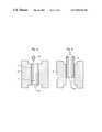
- FIG. 1shows the prior art schematically with a wear liner and a wear liner holder of a high pressure press.
- FIG. 2shows schematically a wear liner according to the invention being inserted into the cylindrical pressure chamber of a high pressure press.
- FIG. 3shows a wear liner according to the invention being expanded and radially pre-stressed inside the cylindrical pressure chamber of a high pressure press.
- FIG. 4shows a wear liner according to the invention in position in the cylindrical pressure chamber of a high pressure press.
- FIG. 5shows cuts being made inside a wear liner according to the present invention prior to removing it from a high pressure press.
- FIG. 6shows a dismantled wear liner according to the present invention being removed from a high pressure press.
- a replaceable wear liner according to the present inventionis shaped as thin-walled circular cylinder, although other cylindrical shapes are within the scope of the invention.
- the outside diameter of a wear liner according to the present inventionis slightly undersize compared to the inside diameter of the cylindrical pressure chamber or liner holder of a high-pressure press 3 .
- the wear liner 1 shown in FIG. 2is inserted in the cylindrical pressure chamber 2 . Once placed inside the cylindrical pressure chamber 2 the wear liner is fixed in place by the application of an excess radial pressure. This is carried out by closing the press 3 and applying a pre-calculated excess pressure to the wear liner inside the press 3 , as shown schematically by letter “P” in FIG. 3 . This plastically deforms the wear liner leaving it with a residual compressive stress that acts as a radial pre-stress against the high pressures generated in use inside the press 3 .
- the wear liner 1is put in place inside the cylindrical pressure chamber 2 inside the press 3 .
- Two end caps 5 , 6are placed in position at either end of the wear liner.
- the end caps 5 , 6are each equipped with a temporary sealing means in the form of temporary undersize end cap seals 7 , 8 which fit inside the ends of the wear liner 1 .
- the inside diameter of the wear lineris undersize when first fitted, which means that the end cap seals 7 , 8 have to be of a slightly smaller diameter than seals for normal service.
- pressuremay be applied inside the wear liner, by means of fluid under pressure supplied by an external pressure source delivered by means such as a pipe (not shown) arranged to pass through an end cap 5 , 6 .
- the wear linerUnder sufficient excess pressure, above the yield point of the material, the wear liner is deformed and permanently expanded to a pre-calculated degree. The pressure is released. The end caps 5 , 6 are removed. The end parts of the wear liner that were adjacent to the end caps and which were not under pressure may have a smaller inside diameter than the main part of the wear liner which was exposed to pressure. When necessary, the inner surface of the undeformed regions of the wear liner adjacent to the end caps may be machined to increase the inside diameter so that it is the same as the rest of the wear liner. The machining can be done before or after the expansion of the wear liner.
- a wear liner according to the inventionmay be removed, either because of a crack or a fracture failure or as part of a planned maintenance operation, as follows.
- One or both end caps 5 , 6 with seals 7 , 8 of the high pressure press 3are removed, depending on the type of press 3 .
- a milling cutter 9 or other type of cutting, milling or grinding toolis arranged to be lowered into the wear liner 1 as shown in FIG. 5 .
- the milling cutter 9is operated so as to make a series of longitudinal cuts 10 running the whole length of the liner. Usually four cuts distributed approximately evenly around the circumference provide sufficient effect. Fewer or more cuts may be used depending on the diameter of the wear liner.
- the cutsare made to a pre-determined depth, as deep as possible in the wear liner material, leaving a thickness of between 1–10% and preferably between 1–5% of the diameter of the wear liner diameter in place.
- the collapsed wear liner 11can then be removed quite easily from the cylindrical pressure chamber 2 and lifted clear with a standard lifting apparatus as shown in FIG. 6 . After the old wear liner has been dismantled and removed a new wear liner can be quickly and easily put in place as described above.
Landscapes
- Chemical & Material Sciences (AREA)
- Engineering & Computer Science (AREA)
- Mechanical Engineering (AREA)
- Chemical Kinetics & Catalysis (AREA)
- Life Sciences & Earth Sciences (AREA)
- Organic Chemistry (AREA)
- Zoology (AREA)
- Physics & Mathematics (AREA)
- Fluid Mechanics (AREA)
- Polymers & Plastics (AREA)
- Food Science & Technology (AREA)
- Wood Science & Technology (AREA)
- Press Drives And Press Lines (AREA)
- Automatic Assembly (AREA)
Abstract
Description
Claims (3)
Applications Claiming Priority (2)
| Application Number | Priority Date | Filing Date | Title |
|---|---|---|---|
| SE9802069ASE514243C2 (en) | 1998-06-09 | 1998-06-09 | Method of providing a high-pressure press as well as a high-pressure press |
| PCT/SE1999/000963WO1999064144A1 (en) | 1998-06-09 | 1999-06-04 | Device and method for a high pressure press |
Publications (1)
| Publication Number | Publication Date |
|---|---|
| US6895856B1true US6895856B1 (en) | 2005-05-24 |
Family
ID=20411654
Family Applications (1)
| Application Number | Title | Priority Date | Filing Date |
|---|---|---|---|
| US09/719,289Expired - Fee RelatedUS6895856B1 (en) | 1998-06-09 | 1999-06-04 | Device and method for a high pressure press |
Country Status (8)
| Country | Link |
|---|---|
| US (1) | US6895856B1 (en) |
| EP (1) | EP1115477B1 (en) |
| AU (1) | AU4810399A (en) |
| BR (1) | BR9911138A (en) |
| DE (1) | DE69915321T2 (en) |
| ES (1) | ES2216534T3 (en) |
| SE (1) | SE514243C2 (en) |
| WO (1) | WO1999064144A1 (en) |
Cited By (3)
| Publication number | Priority date | Publication date | Assignee | Title |
|---|---|---|---|---|
| US7469626B2 (en) | 2005-07-29 | 2008-12-30 | Honeywell International, Inc. | Split ceramic bore liner, rotor body having a split ceramic bore liner and method of lining a rotor bore with a split ceramic bore liner |
| JP2009500551A (en)* | 2005-07-06 | 2009-01-08 | チーム オリオン ヨーロッパ エス.エー. | 2-stroke engine especially for land craft, water craft or air craft models |
| US20150020360A1 (en)* | 2014-10-09 | 2015-01-22 | Caterpillar Inc. | Method of removing a bushing from a machine component |
Families Citing this family (1)
| Publication number | Priority date | Publication date | Assignee | Title |
|---|---|---|---|---|
| EP1201139A1 (en)* | 2000-10-26 | 2002-05-02 | SIG Simonazzi S.p.A. | Pressurization Device |
Citations (11)
| Publication number | Priority date | Publication date | Assignee | Title |
|---|---|---|---|---|
| US4198740A (en)* | 1978-07-24 | 1980-04-22 | The United States Of America As Represented By The United States Department Of Energy | Method for forming or bonding a liner |
| EP0013927A1 (en) | 1979-01-18 | 1980-08-06 | INTERATOM Internationale Atomreaktorbau GmbH | Bimetal cylinder for plastics processing machinery |
| US4328959A (en) | 1980-11-14 | 1982-05-11 | Gerwin Holtmann | Method and device for removing used refractory lining and/or slag deposits from elongated vessels |
| US4359811A (en)* | 1980-08-20 | 1982-11-23 | The Halcon Sd Group, Inc. | Method of coating or lining metals |
| US4377894A (en)* | 1980-03-21 | 1983-03-29 | Kawasaki Jukogyo Kabushiki Kaisha | Method of lining inner wall surfaces of hollow articles |
| US4449281A (en)* | 1982-03-16 | 1984-05-22 | Kawasaki Jukogyo Kabushiki Kaisha | Method of producing multiple-wall, composite tubular structures |
| US5209197A (en)* | 1990-09-06 | 1993-05-11 | Melchior Jean F | Cylinder head/cylinder sealing device for a reciprocating pressurized gas machine |
| US5287621A (en) | 1992-02-12 | 1994-02-22 | Usui Kokusai Sangyo Kaisha Ltd. | Cylinder liner manufacturing process |
| WO1994021370A1 (en) | 1993-03-19 | 1994-09-29 | Asea Brown Boveri Ab | High-pressure press |
| WO1995021690A1 (en) | 1994-02-14 | 1995-08-17 | Asea Brown Boveri Ab | High pressure press and method for high pressure treatment of substances |
| US5475911A (en)* | 1993-05-20 | 1995-12-19 | Wells; Gary L. | Multi-stage dual wall hydroforming |
- 1998
- 1998-06-09SESE9802069Apatent/SE514243C2/ennot_activeIP Right Cessation
- 1999
- 1999-06-04USUS09/719,289patent/US6895856B1/ennot_activeExpired - Fee Related
- 1999-06-04EPEP99931660Apatent/EP1115477B1/ennot_activeExpired - Lifetime
- 1999-06-04ESES99931660Tpatent/ES2216534T3/ennot_activeExpired - Lifetime
- 1999-06-04DEDE69915321Tpatent/DE69915321T2/ennot_activeExpired - Fee Related
- 1999-06-04AUAU48103/99Apatent/AU4810399A/ennot_activeAbandoned
- 1999-06-04WOPCT/SE1999/000963patent/WO1999064144A1/enactiveIP Right Grant
- 1999-06-04BRBR9911138-1Apatent/BR9911138A/ennot_activeApplication Discontinuation
Patent Citations (13)
| Publication number | Priority date | Publication date | Assignee | Title |
|---|---|---|---|---|
| US4198740A (en)* | 1978-07-24 | 1980-04-22 | The United States Of America As Represented By The United States Department Of Energy | Method for forming or bonding a liner |
| EP0013927A1 (en) | 1979-01-18 | 1980-08-06 | INTERATOM Internationale Atomreaktorbau GmbH | Bimetal cylinder for plastics processing machinery |
| US4377894A (en)* | 1980-03-21 | 1983-03-29 | Kawasaki Jukogyo Kabushiki Kaisha | Method of lining inner wall surfaces of hollow articles |
| US4359811A (en)* | 1980-08-20 | 1982-11-23 | The Halcon Sd Group, Inc. | Method of coating or lining metals |
| US4328959A (en) | 1980-11-14 | 1982-05-11 | Gerwin Holtmann | Method and device for removing used refractory lining and/or slag deposits from elongated vessels |
| US4449281A (en)* | 1982-03-16 | 1984-05-22 | Kawasaki Jukogyo Kabushiki Kaisha | Method of producing multiple-wall, composite tubular structures |
| US5209197A (en)* | 1990-09-06 | 1993-05-11 | Melchior Jean F | Cylinder head/cylinder sealing device for a reciprocating pressurized gas machine |
| US5287621A (en) | 1992-02-12 | 1994-02-22 | Usui Kokusai Sangyo Kaisha Ltd. | Cylinder liner manufacturing process |
| WO1994021370A1 (en) | 1993-03-19 | 1994-09-29 | Asea Brown Boveri Ab | High-pressure press |
| US5622105A (en) | 1993-03-19 | 1997-04-22 | Asea Brown Boveri Ab | High-pressure press |
| US5475911A (en)* | 1993-05-20 | 1995-12-19 | Wells; Gary L. | Multi-stage dual wall hydroforming |
| WO1995021690A1 (en) | 1994-02-14 | 1995-08-17 | Asea Brown Boveri Ab | High pressure press and method for high pressure treatment of substances |
| US5765465A (en) | 1994-02-14 | 1998-06-16 | Asea Brown Boveri Ab | High pressure press and method for high pressure treatment of substances |
Cited By (4)
| Publication number | Priority date | Publication date | Assignee | Title |
|---|---|---|---|---|
| JP2009500551A (en)* | 2005-07-06 | 2009-01-08 | チーム オリオン ヨーロッパ エス.エー. | 2-stroke engine especially for land craft, water craft or air craft models |
| JP4913135B2 (en)* | 2005-07-06 | 2012-04-11 | チーム オリオン ヨーロッパ エス.エー. | 2-stroke engine especially for land craft, water craft or air craft models |
| US7469626B2 (en) | 2005-07-29 | 2008-12-30 | Honeywell International, Inc. | Split ceramic bore liner, rotor body having a split ceramic bore liner and method of lining a rotor bore with a split ceramic bore liner |
| US20150020360A1 (en)* | 2014-10-09 | 2015-01-22 | Caterpillar Inc. | Method of removing a bushing from a machine component |
Also Published As
| Publication number | Publication date |
|---|---|
| WO1999064144A1 (en) | 1999-12-16 |
| AU4810399A (en) | 1999-12-30 |
| DE69915321D1 (en) | 2004-04-08 |
| ES2216534T3 (en) | 2004-10-16 |
| SE514243C2 (en) | 2001-01-29 |
| EP1115477A1 (en) | 2001-07-18 |
| SE9802069D0 (en) | 1998-06-09 |
| SE9802069L (en) | 2000-01-18 |
| EP1115477B1 (en) | 2004-03-03 |
| BR9911138A (en) | 2001-10-23 |
| DE69915321T2 (en) | 2005-02-24 |
Similar Documents
| Publication | Publication Date | Title |
|---|---|---|
| US4417459A (en) | Autofrettage process | |
| US4571969A (en) | Autofrettage process | |
| EP2406536B1 (en) | Pressure vessel for a high pressure press | |
| AU692844B2 (en) | High pressure press and method for high pressure treatment of substances | |
| US5235836A (en) | Seal head for tube expansion apparatus | |
| US6895856B1 (en) | Device and method for a high pressure press | |
| US4498220A (en) | Method for pre-expanding heat exchanger tube | |
| US6491882B1 (en) | High-pressure device | |
| US2861530A (en) | Method and apparatus for making metal articles | |
| EP1384008B1 (en) | Surface densification of powder metal bearing caps | |
| WO1999061146A9 (en) | High-pressure apparatus | |
| US20050249615A1 (en) | High pressure reciprocating pump | |
| US5622105A (en) | High-pressure press | |
| MXPA00012226A (en) | Device and method for a high pressure press | |
| US4339935A (en) | Method for calibrating tubular articles | |
| US8302447B2 (en) | Device for forging bush-shaped objects and a forged part produced therewith | |
| CN109372461A (en) | Method for resetting wellhead device out of control of blowout | |
| RU2176182C2 (en) | Method of and device for reconditioning of inner surface of cylinder liners in internal combustion engines | |
| EP1313591A1 (en) | Method for the plastic moulding of the hub recess for a fast running turbine component | |
| EP0740970A2 (en) | Seal head for tube expansion apparatus | |
| Giacomelli et al. | Safety Aspects of design of cylinders and hyper-compressors for LDPE | |
| EP2228197A1 (en) | Apparatus, system, and method of manufacturing a composite tubular using a stiffened mandrel | |
| HUE026149T2 (en) | Packing cups manufacturing | |
| JP2008086962A (en) | Drum structure of high-pressure vessel having cylindrical drum and method for manufacturing drum | |
| SU1655753A1 (en) | Piston rings manufacturing technique |
Legal Events
| Date | Code | Title | Description |
|---|---|---|---|
| AS | Assignment | Owner name:FLOW HOLDINGS GMBH (SAGL) LIMITED LIABILITY COMPAN Free format text:ASSIGNMENT OF ASSIGNORS INTEREST;ASSIGNOR:LONNEBORG, NILS-GUNNAR;REEL/FRAME:011606/0518 Effective date:20010112 | |
| AS | Assignment | Owner name:BANK OF AMERICA, N.A.., WASHINGTON Free format text:SECURITY AGREEMENT;ASSIGNOR:FLOW INTERNATIONAL CORPORATION;REEL/FRAME:013306/0063 Effective date:20020823 | |
| AS | Assignment | Owner name:JOHN HANCOCK LIFE INSURANCE COMPANY, AS COLLATERAL Free format text:SECURITY INTEREST;ASSIGNOR:FLOW INTERNATIONAL CORPORATION;REEL/FRAME:013447/0301 Effective date:20021001 | |
| AS | Assignment | Owner name:BANK OF AMERICA, N.A., WASHINGTON Free format text:SECURITY AGREEMENT;ASSIGNOR:FLOW HOLDINGS SAGL;REEL/FRAME:014615/0205 Effective date:20030728 | |
| AS | Assignment | Owner name:BANK OF AMERICA, N.A.,WASHINGTON Free format text:SECURITY AGREEMENT;ASSIGNOR:FLOW INTERNATIONAL CORPORATION;REEL/FRAME:016283/0522 Effective date:20050708 Owner name:BANK OF AMERICA, N.A., WASHINGTON Free format text:SECURITY AGREEMENT;ASSIGNOR:FLOW INTERNATIONAL CORPORATION;REEL/FRAME:016283/0522 Effective date:20050708 | |
| AS | Assignment | Owner name:FLOW INTERNATIONAL CORPORATION,WASHINGTON Free format text:RELEASE BY SECURED PARTY;ASSIGNOR:BANK OF AMERICA, N.A.;REEL/FRAME:016745/0894 Effective date:20051031 Owner name:FLOW INTERNATIONAL CORPORATION, WASHINGTON Free format text:RELEASE BY SECURED PARTY;ASSIGNOR:BANK OF AMERICA, N.A.;REEL/FRAME:016745/0881 Effective date:20051031 Owner name:FLOW INTERNATIONAL CORPORATION, WASHINGTON Free format text:RELEASE BY SECURED PARTY;ASSIGNOR:BANK OF AMERICA, N.A.;REEL/FRAME:016745/0894 Effective date:20051031 | |
| AS | Assignment | Owner name:FLOW INTERNATIONAL CORPORATION, WASHINGTON Free format text:RELEASE BY SECURED PARTY;ASSIGNOR:JOHN HANCOCK LIFE INSURANCE COMPANY;REEL/FRAME:016761/0670 Effective date:20051031 | |
| AS | Assignment | Owner name:AVURE TECHNOLOGIES AB,SWEDEN Free format text:ASSIGNMENT OF ASSIGNORS INTEREST;ASSIGNOR:FLOW HOLDINGS SAGL;REEL/FRAME:016769/0128 Effective date:20051031 Owner name:AVURE TECHNOLOGIES AB, SWEDEN Free format text:ASSIGNMENT OF ASSIGNORS INTEREST;ASSIGNOR:FLOW HOLDINGS SAGL;REEL/FRAME:016769/0128 Effective date:20051031 | |
| FEPP | Fee payment procedure | Free format text:PAYOR NUMBER ASSIGNED (ORIGINAL EVENT CODE: ASPN); ENTITY STATUS OF PATENT OWNER: LARGE ENTITY | |
| FPAY | Fee payment | Year of fee payment:4 | |
| REMI | Maintenance fee reminder mailed | ||
| LAPS | Lapse for failure to pay maintenance fees | ||
| STCH | Information on status: patent discontinuation | Free format text:PATENT EXPIRED DUE TO NONPAYMENT OF MAINTENANCE FEES UNDER 37 CFR 1.362 | |
| FP | Lapsed due to failure to pay maintenance fee | Effective date:20130524 |