US6895834B1 - Adjustable crank for bicycles - Google Patents
Adjustable crank for bicyclesDownload PDFInfo
- Publication number
- US6895834B1 US6895834B1US10/679,242US67924203AUS6895834B1US 6895834 B1US6895834 B1US 6895834B1US 67924203 AUS67924203 AUS 67924203AUS 6895834 B1US6895834 B1US 6895834B1
- Authority
- US
- United States
- Prior art keywords
- crank arm
- spindle
- bores
- boss
- rotational axis
- Prior art date
- Legal status (The legal status is an assumption and is not a legal conclusion. Google has not performed a legal analysis and makes no representation as to the accuracy of the status listed.)
- Expired - Lifetime, expires
Links
Images


Classifications
- B—PERFORMING OPERATIONS; TRANSPORTING
- B62—LAND VEHICLES FOR TRAVELLING OTHERWISE THAN ON RAILS
- B62M—RIDER PROPULSION OF WHEELED VEHICLES OR SLEDGES; POWERED PROPULSION OF SLEDGES OR SINGLE-TRACK CYCLES; TRANSMISSIONS SPECIALLY ADAPTED FOR SUCH VEHICLES
- B62M3/00—Construction of cranks operated by hand or foot
- B62M3/02—Construction of cranks operated by hand or foot of adjustable length
- Y—GENERAL TAGGING OF NEW TECHNOLOGICAL DEVELOPMENTS; GENERAL TAGGING OF CROSS-SECTIONAL TECHNOLOGIES SPANNING OVER SEVERAL SECTIONS OF THE IPC; TECHNICAL SUBJECTS COVERED BY FORMER USPC CROSS-REFERENCE ART COLLECTIONS [XRACs] AND DIGESTS
- Y10—TECHNICAL SUBJECTS COVERED BY FORMER USPC
- Y10T—TECHNICAL SUBJECTS COVERED BY FORMER US CLASSIFICATION
- Y10T74/00—Machine element or mechanism
- Y10T74/21—Elements
- Y10T74/2164—Cranks and pedals
- Y10T74/2167—Variable
Definitions
- the present inventionrelates generally to transmissions, and more particularly, to crank arms of crank assemblies for bicycles.
- Cyclingis a very popular activity for both recreational riders and racing enthusiasts alike. Professional cyclists and triathletes are earning large sums of money through races, sponsorships, and advertisements.
- bicycle configurationincluding frame size, frame geometry, and crank arm length, is an important aspect for proper efficiency and comfort. While there as been various improvements to the bicycle in recent years, there has never been an easy and efficient method for determining the optimal crank arm length for a specific rider.
- a ridereither purchases a bicycle with any one of a variety of standard crank arm lengths, including 170 mm and 175 mm crank arm lengths, or orders the bicycle with his/her preferred crank arm length.
- a riderwishes to change the length of the crank arms of a bicycle crankset, the rider must begin the labor intensive and time consuming task of removing the crank arms from the spindle, and reattaching a different length set of crank arms to the spindle.
- the ridermust repeat the process. If the rider wishes to try a non-standard size, the rider must have the crank arms fabricated, which takes many months to receive, and is extremely expensive.
- the present inventionis directed to such a system and method.
- an adjustable length crank armin accordance with one embodiment of the present invention, includes a first member having a spindle bore sized and configured to be connectable to a spindle and defining a spindle rotational axis.
- the crank armfurther includes an elongate second member rotatably connected at one end to the first member and having a mounting bore disposed at the opposite end of the second member.
- the mounting boreis adapted to be connected to a pedal shaft and defines a pedal rotational axis spaced a distance X from the spindle rotational axis and parallel therewith.
- the second memberis selectively rotatable between at least two pre-selected positions about a rotational axis eccentric with respect to the spindle rotational axis. The pre-selected positions of the second member vary the distance X between the spindle rotational axis and the pedal rotational axis.
- a crank arm having an adjustable effective lengthincludes a base member having a cylindrically shaped first boss, and a spindle bore sized and configured to be connectable to a spindle and defining a spindle rotational axis parallel and eccentric to an axis of the first boss.
- the crank armalso includes an elongate crank arm member journaled for rotation onto the first boss at one end and having a mounting bore disposed at the other end adapted to be connected to a pedal shaft and defining a pedal rotational axis spaced apart a distance from the spindle rotational axis and parallel therewith. The spaced apart distance defines an effective length of the crank arm.
- the crank arm memberis operable to be selectively rotated between a plurality of pre-selected positions about the axis of the first boss, and further operable to be selectively connected to the base member for rotation therewith.
- the effective length of the crank armis adjustable as the crank arm member rotates between the plurality of pre-selected positions.
- an adjustable length crank armin accordance with yet another embodiment of the present invention, includes a disk shaped base member having a spindle facing side and a crank arm member facing side.
- the base memberincludes a cylindrically shaped first boss having a cylindrical open cavity.
- the base memberfurther includes a spindle through bore connected to the cavity.
- the spindle through boreis adapted for receiving a spindle in a non-rotational manner and defines a spindle rotational axis.
- the base memberfurther includes at least two through bores having centers disposed radially outward of the perimeter of the first boss and centered on an imaginary circle having a pre-selected diameter.
- the crank armalso includes a crank arm member having a spindle end and a pedal end.
- the spindle end of the crank arm memberdefines a cylindrical bore sized and configured for rotatably mounting the crank arm member onto the first boss and includes at least one fastener through bore.
- the pedal end of the crank arm memberdefines a through bore adapted to be connected to a pedal shaft and defines a pedal rotational axis spaced a distance D from the spindle rotational axis.
- the crank arm memberis rotatable about the first boss for selectively aligning the fastener through bore with one of the base member through bores. The rotation of the crank arm member selectively changes the distance D.
- the crank armfurther includes at least one fastener received through the aligned fastener through bore and one of the base member through bores for selectively coupling the base member to the crank arm member for rotation therewith.
- FIG. 1is a partial perspective view of a bicycle to which crank arms constructed in accordance with the present invention are mounted;
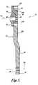
- FIG. 2is an exploded view of the crank assembly of FIG. 1 ;
- FIG. 3Ais a front perspective view of the base member of the left crank arm shown in FIG. 2 ;
- FIG. 3Bis a front elevational view of the base member of the left crank arm shown in FIG. 2 ;
- FIG. 3Cis a rear perspective view of the base member of the left crank arm shown in FIG. 2 ;
- FIG. 3Dis a rear elevational view of the base member of the left crank arm shown in FIG. 2 ;
- FIG. 4Ais a front perspective view of the base member of the right crank arm shown in FIG. 2 ;
- FIG. 4Bis a front elevational view of the base member of the right crank arm shown in FIG. 2 ;
- FIG. 4Cis a rear perspective view of the base member of the right crank arm shown in FIG. 2 ;
- FIG. 4Dis a rear elevational view of the base member of the right crank arm shown in FIG. 2 ;
- FIG. 5is a cross-sectional view of the left crank arm of FIG. 2 ;
- FIG. 6is a cross-sectional view of the right crank arm of FIG. 2 ;
- FIG. 7is a front elevational view of the left crank arm of FIG. 2 ;
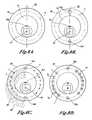
- FIG. 8A–8Dis a sequence depicting one method of positioning and forming the through bores in the base member
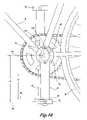
- FIG. 9is a side elevation view of a bicycle to which the crank arms of FIG. 2 are mounted, the crank arms having an effective crank arm length L 1 ;
- FIG. 10is a side elevation view of a bicycle to which the crank arms of FIG. 2 are mounted, the crank arms having an effective crank arm length L 2 ;
- FIG. 11is a side elevation view of a bicycle to which the crank arms of FIG. 2 are mounted, the crank arms having an effective crank arm length L 3 .
- the present inventionis directed to an apparatus for a bicycle or like device for increasing the overall comfort and performance of the rider during use. More specifically, the present invention is directed to an adjustable length crank arm for easily and effectively adjusting the effective crank arm length of a bicycle. While the adjustable length crank arm of the present invention is described herein for use with a bicycle, it will be appreciated that the adjustable length crank arm may be practiced with other crank transmissions, such as the crank assemblies of stationary bicycle exercise trainers. Thus, the following description relating to bicycles is meant to be illustrative and not limiting the broadest scope of the inventions, as claimed.
- FIG. 1illustrates a partial perspective view of a crank assembly 20 operably connected to a bicycle B.
- the crank assembly 20includes an axle (not shown), generally referred to as a spindle, that is mounted within a bottom bracket shell S of the bicycle B for rotation about a spindle rotational axis.
- Left and right crank arms 22 and 24are attached at opposite ends of the spindle for rotation therewith.
- the terms “left” and “right”are used herein to denote the left and right sides of a rider when mounted on the bicycle in the typical riding position, and therefore, should not be considered as limiting the scope of the present invention.
- Left and right pedals 28 and 30are rotatably attached via pedal shafts 32 to the ends of left and right cranks arms 22 and 24 , respectively. Attached for rotation with the right crank arm 24 is at least one chain ring 34 .
- the chain ring 34is configured to connect to a chain (not shown) that couples the chain ring 34 to the rear wheel W through a conventional rear sprocket arrangement (not shown) so that rotation of the pedals 28 and 30 generated by the rider is transmitted to the rear wheel W.
- FIG. 2is an exploded perspective view of the crank assembly 20 illustrating the crank arms 22 and 24 and the spindle 26 (shown mounted in a convention bottom bracket).
- the spindle 26has four flats 36 A– 36 D ( 36 C and 36 D are not shown) machined at a slight angle on each end of the spindle 26 forming tapered square protrusions 38 .
- the tapered square protrusions 38are adapted to fixedly attached to the crank arms 22 and 24 , respectively, by pressing the tapered square protrusions into cooperatively sized and shaped spindle bores of each crank arm.
- a nut or boltmay be tightened against the outer portion of the crank arms 22 and 24 to hold the crank arms onto the spindle 26 as is known in the art.
- the spindle 26is a standard sized, conventional spindle, and thus, will not be described in any more detail.
- Crank arm 22includes a left base member 40 (“base member 40 ”) and a left crank arm member 44 (“crank arm member 44 ”), as shown best in FIGS. 2 , 5 , and 7 .
- the base member 40is disc-shaped, having a cylindrically shaped first boss 48 protruding from the crank arm member side 50 of base member 40 and a frusto-conically shaped second boss 54 protruding from the spindle side 56 of base member 40 .
- the first boss 48is concentrically arranged on the base member 40 and includes a threaded cylindrical cavity 60 , which is eccentric with respect to the first boss 48 .
- the cavity 60extends approximately halfway into the first boss 48 , where it connects and is coaxial with a spindle-mounting bore 66 that extends into the base member 40 and exits through the center of the second boss 54 .
- the spindle-mounting bore 66is sized and configured to receive one of the spindle protrusions in an anti-rotational manner.
- the spindle-mounting bore 66defines a spindle rotational axis 94 (see FIG. 5 ).
- the base member 40further includes a plurality of through bores 70 , which are shown threaded, positioned around the periphery of the base member 40 , radially outward of the first and second bosses 48 and 54 , respectively.
- the positioning of the through bores 70which determine the effective length of the crank arm 22 ( FIG. 2 ), will be described in more detail below.
- the crank arm member 44is formed as an elongate body 80 having a spindle end 82 and a pedal end 84 .
- the pedal end 84 of the crank arm member 44includes a pedal shaft through bore 88 to which a pedal shaft of a pedal is mounted.
- the pedal shaft through bore 88defines a pedal rotational axis 90 .
- the pedal rotational axis 90 of the pedal shaft through bore 88is parallel with the spindle rotational axis 94 .
- a cylindrical aperture 100sized and configured for receiving the first boss 48 of the base member 40 in a rotationally seated or journaled manner.
- the thickness of the crank arm member 44 at the spindle end 82is such that the outer side surface 104 of the crank arm member 44 is flush with the first boss 48 when rotationally seated thereto.
- the crank arm member 44further includes two fastener through bores 110 centered on an imaginary circle having a pitch crank diameter (PCD), the imaginary circle positioned radially outward of the aperture 100 .
- the two fastener through bores 110are also aligned with the longitudinal axis of the crank arm member 44 , as best shown in FIG. 7 .
- the diameter of the two fastener through bores 110are substantially identical to the plurality of through bores 70 in base member 40 .
- the crank arm member 44In operation, to rotationally lock the crank arm member 44 to the base member 40 , the crank arm member 44 is rotated until the two fastener through bores 110 are aligned with two of the plurality of through bores 70 , as shown in FIGS. 5 and 7 , and then fastened together by routing removable fasteners 114 , shown in FIGS. 2 and 7 , such as bolts or detent pins, through the aligned through bores 110 and 70 .
- the through bores 70 of the base member 40can either be threaded, as shown in the FIGS. 2 , 3 A, 3 C, and 5 , or unthreaded, in which a nut can be used to secure the bolt therethrough.
- the crank arm 24includes a right base member 120 (“base member 120 ”) and a right crank arm member 124 (“arm member 124 ”).
- the base member 120is substantially disc-shaped, having a plurality of arms 128 positioned equidistant around its perimeter and projecting radially outward from the center thereof.
- the arms 128include through bores 130 for connecting to the chain ring. It will be appreciated that the base member 120 may be configured so that multiple chain rings of differing diameters may be attached to the arms 128 .
- the base member 120includes a cylindrically shaped first boss 136 protruding from the crank arm member side 138 of base member 120 , and a frusto-conically shaped second boss 144 protruding from the spindle side 146 of base member 120 .
- the second boss 144is concentrically arranged on the base member 120 , while the first boss 136 is positioned offset or eccentric with respect to the base member 120 .
- the first boss 136includes a threaded cylindrical cavity 150 , which is eccentric with respect to the first boss 136 , but concentric with the base member 120 .
- the cavity 150extends approximately halfway into the first boss 136 , where it connects with a spindle-mounting bore 154 that extends into the base member 120 and exits through the center of the second boss 144 .
- the spindle-mounting bore 154is concentric with respect to the base member 120 , and is sized and configured for receiving one of the spindle protrusions in an anti-rotational manner.
- the spindle-mounting boredefines a spindle rotational axis 194 , which is coaxial with the spindle rotational axis of the left crank arm.
- the base member 120further includes a plurality of through bores 160 , which are shown threaded, positioned radially outward of the perimeter of first boss 136 . The positioning of the through bores 160 , which determine the effective length of the crank arm 124 , will be described in more detail below.
- the crank arm member 124is substantially identical to the crank arm member 44 ( FIG. 5 ) in materials, construction, and operation. As best shown in FIG. 6 , the crank arm member 124 is formed as an elongate body 180 having a spindle end 182 and a pedal end 184 . The pedal end 184 of the crank arm member 124 includes a pedal shaft through bore 188 to which a pedal shaft of a pedal is mounted. When assembled, a pedal rotational axis 190 of the pedal shaft through bore 188 is parallel with the spindle rotational axis 194 , as best shown in FIG. 6 .
- crank arm member 124At the spindle end 182 of the crank arm member 124 , there is formed a cylindrical aperture 200 sized and configured for receiving the first boss 136 of the base member 120 in a rotationally seated or journaled manner.
- the thickness of the crank arm member 124 at the spindle end 182is such that the outer side surface 204 of the crank arm member 124 is flush with the first boss 136 when rotationally coupled thereto.
- the crank arm member 124further includes two fastener through bores 210 centered on an imaginary circle having a pitch crank diameter (PCD), the imaginary circle positioned radially outward of the aperture 200 .
- the two fastener through bores 210are aligned with the longitudinal axis of the crank arm member 124 , as best shown in FIG. 2 .
- the diameter of the two fastener through bores 210are substantially identical to the plurality of through bores 160 in member 120 .
- the crank arm member 124In operation, to rotationally lock the crank arm member 124 to the base member 120 , the crank arm member 124 is rotated until the two fastener through bores 210 are aligned with two of the plurality of through bores 160 , as shown in FIG. 6 , and then fastened together by routing removable fasteners 214 , shown in FIG. 2 , such as bolts or detent pins, through the aligned through bores 210 and 160 .
- the through bores 160can either be threaded, as shown in the FIGS. 2 , 4 A, 4 C, and 6 , or unthreaded, in which a nut can be used to secure the bolt therethrough.
- FIGS. 8A–8Dthere is shown a manufacturing sequence to form the through bores 70 in the base member 40 .
- the method of positioning the through bores 160 of the base member 120( FIG. 4A–4D ) is substantially identical.
- an imaginary circle C having a PCD equal to the distance between the fastener through bores of the crank arm memberis scribed onto the base member 40 , as shown best in FIG. 8A .
- a bisecting line BLis scribed onto the base member 40 .
- the bisecting line BLintersects the spindle rotational axis 94 and the rotational axis RA of the crank arm member.
- the first two through boresdesignated as 70 A and 70 B, only in FIGS. 8B–8D , are formed, such as by drilling, at the intersection of the circle C and the bisecting line BL, as shown in FIG. 7B .
- a plurality of semi-circles SC of differing diametersare scribed, as shown in FIG. 7C , each having their centers at the spindle rotational axis 94 .
- the diameters of the semi-circles SCdiffer by the amount of incremental change desired in the adjustable crank arm. For example, in the embodiment shown, the diameters differ in the amount of 2.5 mm, thereby creating an adjustable crank arm that can incrementally change in effective length by 2.5 mm.
- custom lengthsmay be used instead of the standard 2.5 mm increments, such as 2 mm, 1.5 mm, and 3 mm, to name a few.
- any number of through bores 70may be used, as long as they can be positioned around the base member 40 . As such, the number of through bores 70 determines the total number of incremental length changes that can be made by the crank arms.
- the offset distance of the spindle rotational axis 94 from the crank arm member rotational axis RAdetermines one half of the total range of change in effective crank arm length. As such, the offset distance may vary in various embodiments of the present invention.
- the remaining through bores 70are formed, such as by drilling, at the intersections I of the circle C and the semi-circles SC, as shown in FIGS. 8C and 8D .
- the use of semi-circlescorrespond with the use of one fastener and one fastener through bore 110 in the crank arm member 44 , which is an embodiment of the present invention.
- the semi-circleswould be scribed as full circles.
- the through bores 70are tapped to create internal threads.
- the crank arms of the present inventionmay be selectively adjusted to change the effective length of the crank arm (i.e., the distance between the pedal rotational axis and the spindle rotational axis) from between 165 mm and 185 mm in 2.5 mm increments to coincide with the standard length of crank arms commercially available at bicycle shops.
- the present inventionmay be modified to change the desired effective length of the crank arms, the total range of possible effective crank arm lengths, and/or the amount of incremental change.
- crank arms of the present inventioncan be designed to have an effective crank arm length range larger or smaller than 165 mm to 185 mm, or have constant incremental changes in sizes other than the standard 2.5 mm (e.g., 1.0 mm, 1.50 mm, 1.75 mm, etc.) or varying incremental changes in effective crank arm length.
- one varying incremental seriescould begin with 2.5 mm, 1.0 mm, 1.5 mm, 2.0 mm, 2.5 mm, etc.
- FIG. 9is a side elevational view of a bicycle to which the crank arms 22 and 24 are rotationally mounted.
- crank arm 22will be described.
- the operation of the crank arm 24is substantially identical to that of crank arm 22 .
- FIG. 9is a side elevational view of a bicycle to which the crank arms 22 and 24 are rotationally mounted.
- crank arms 22 and 24are vertically aligned and extend in opposite directions (approximately 180 degrees from one another), the fasteners 114 have been routed through the desired aligned through bores 70 for selecting the desired effective crank arm length L 1 (i.e., the distance between the pedal rotational axis 90 and the spindle rotational axis 94 ), and for selectively connecting the base member 40 to the crank arm member 44 in a non-rotational manner.
- L 1i.e., the distance between the pedal rotational axis 90 and the spindle rotational axis 94
- the force imparted on the pedals 28 and 30 in a direction substantially tangential to the pedal rotational axisrotates the crank arms 22 and 24 about the spindle rotational axis, which in turn, rotates the chain ring 34 .
- the rotation of the chain ring 34is transmitted to the rear wheel W of the bicycle through a chain N.
- FIG. 10is a side elevational view of a bicycle to which the crank arms 22 and 24 are rotationally mounted.
- the crank arms 22 and 24vertically extend in opposite directions (approximately 180 degrees from one another), and the fasteners 114 have been routed through the desired aligned through bores 70 for selecting the desired effective crank arm length L 2 , which is greater than the effective length L 1 shown in phantom.
- the new desired effective crank arm length L 2i.e., the distance between the pedal rotational axis 90 and the spindle rotational axis 94 ) shown in FIG. 10 , the following steps are performed.
- the fasteners 114are removed and the crank arm member 44 is rotated about the first boss 48 until the fastener through bores 110 are aligned with the through bores 70 associated with the desired effective crank arm length L 2 .
- the fasteners 114are routed through the aligned through bores 110 , 70 to couple the base member 40 to the crank arm member 44 so that the rotation of the crank arm member 44 is transmitted to the spindle (not shown) through the base member 40 .
- the crank arm 22is rotated downwardly to achieved the orientation shown in FIG. 10 .
- the change in effective lengths between L 1 and L 2is caused by the eccentric relationship of the spindle rotational axis 94 (i.e., the axis of rotation of the crank arm 22 when the crank arm member 44 is coupled to the base member (hidden by the member 44 in FIG. 10 ) in a non-rotational manner, and the rotational axis RA (See FIGS. 8A–8C ) of the crank arm member 44 (i.e., the axis of rotation of the crank arm member 44 about first boss 48 when the crank arm member 44 is coupled for rotation to the base member (hidden by the member 44 in FIG. 10 )).
- crank arms of the present inventioncan change the length between the axes of the spindle and the pedal shaft just by changing the circumferential angular positions of the crank arm members with respect to the base members.
- crank arm membersmay include index markings, such as lines or indicia, which cooperate with an index marking on the first bosses to aid in the alignment or selection of the desired effective crank arm lengths.
- FIG. 11is a side elevational view of a bicycle to which the crank arms 22 and 24 are rotationally mounted.
- the crank arms 22 and 24are vertically aligned and extend in opposite directions (approximately 180 degrees from one another), the fasteners 114 have been routed through the desired aligned through bores 70 for selecting the desired effective crank arm length L 3 , which is greater than the effective lengths L 1 and L 2 shown in phantom.
- the steps described above for the effective crank length L 2are repeated, except for the fastener through bores 110 are aligned with the through bores 70 associated with the desired effective crank arm length L 3 .
- crank arms of the present inventionmay be attached to a bicycle so that the rider can easily and effectively alter the effective length of the crank arms during normal training to determine which crank length provides the best feel and performance.
- the ridermay switch to a fixed length crank arm having the desired effective crank arm length, or the crank arms of the present invention may remain on the bicycle at the desired effective crank length.
- a custom frame or bicycle buildermay utilize the crank arms of the present invention when designing a custom frame for a customer. The present invention allows the custom frame builder to vary the effective crank length, in conjunction with varying the frame size and frame geometry, to provide the customer with the optimal bicycle configuration.
- crank arms of the present inventionmay be used with stationary bicycle trainers, such as the one described in U.S. patent application Ser. No. 09/718,885, filed Nov. 21, 2000, the disclosure of which is hereby incorporated by reference.
- the crank arms of the present inventionwhen used in conjunction with such a trainer can provide a quantitative measure as to what crank arm length the rider is more efficient.
- the aforementioned trainercan output a constant resistance load, e.g., 200 watts at a constant RPM.
- the riderexercises at a constant load, and a constant RPM, and their heart rate is measured. The optimum crank length will result in which crank arm length was associated with the lowest recorded heart rate.
Landscapes
- Engineering & Computer Science (AREA)
- Chemical & Material Sciences (AREA)
- Combustion & Propulsion (AREA)
- Transportation (AREA)
- Mechanical Engineering (AREA)
- Shafts, Cranks, Connecting Bars, And Related Bearings (AREA)
Abstract
Description
Claims (16)
Priority Applications (1)
| Application Number | Priority Date | Filing Date | Title |
|---|---|---|---|
| US10/679,242US6895834B1 (en) | 2002-10-04 | 2003-10-03 | Adjustable crank for bicycles |
Applications Claiming Priority (2)
| Application Number | Priority Date | Filing Date | Title |
|---|---|---|---|
| US41649302P | 2002-10-04 | 2002-10-04 | |
| US10/679,242US6895834B1 (en) | 2002-10-04 | 2003-10-03 | Adjustable crank for bicycles |
Publications (1)
| Publication Number | Publication Date |
|---|---|
| US6895834B1true US6895834B1 (en) | 2005-05-24 |
Family
ID=34594422
Family Applications (1)
| Application Number | Title | Priority Date | Filing Date |
|---|---|---|---|
| US10/679,242Expired - LifetimeUS6895834B1 (en) | 2002-10-04 | 2003-10-03 | Adjustable crank for bicycles |
Country Status (1)
| Country | Link |
|---|---|
| US (1) | US6895834B1 (en) |
Cited By (86)
| Publication number | Priority date | Publication date | Assignee | Title |
|---|---|---|---|---|
| US20060234838A1 (en)* | 2005-04-14 | 2006-10-19 | Icon Ip, Inc. | Method and system for varying stride in an elliptical exercise machine |
| US20080315553A1 (en)* | 2007-06-21 | 2008-12-25 | Guillaume Girout | Bicycle adapted to different forms of cycling |
| GB2451647A (en)* | 2007-08-06 | 2009-02-11 | Ming Cycle Ind Co Ltd | A belt drive bicycle frame with an eccentric bottom bracket |
| US20090199677A1 (en)* | 2008-02-12 | 2009-08-13 | Niner, Inc. | Bicycle eccentric bottom bracket |
| US7717446B2 (en) | 2006-11-21 | 2010-05-18 | Pt Motion Works, Inc. | Self-propelled vehicle propelled by an elliptical drive train |
| US20100167881A1 (en)* | 2008-12-31 | 2010-07-01 | Day Franklin J | Crank mechanism and bicycle incorporating same |
| US20100295262A1 (en)* | 2009-05-19 | 2010-11-25 | Pt Motion Works, Inc. | Folding Steering Column for Elliptical Bike and Method of Use |
| US20100298101A1 (en)* | 2009-05-19 | 2010-11-25 | Pt Motion Works, Inc. | Adjustable Crank Arms for Elliptical Bike and Method of Use |
| US20110041648A1 (en)* | 2008-04-19 | 2011-02-24 | Strala B.V. | Bicycle Pedal |
| USD633416S1 (en) | 2010-03-17 | 2011-03-01 | Pt Motion Works, Inc. | Elliptical bicycle frame |
| USD633827S1 (en) | 2010-03-17 | 2011-03-08 | Pt Motion Works, Inc. | Elliptical bicycle frame |
| US8061728B2 (en) | 2009-05-19 | 2011-11-22 | Pt Motion Works, Inc. | Interlocking guide tracks for elliptical bike and method of use |
| US20130165283A1 (en)* | 2011-12-22 | 2013-06-27 | Travis BRAUN | Eccentric Bottom Bracket Assembly |
| US20130214507A1 (en)* | 2012-02-03 | 2013-08-22 | Industries Rad Inc. | Bicycle frame with adjustable geometry |
| US20140049020A1 (en)* | 2012-08-15 | 2014-02-20 | Cycling Sports Group, Inc. | Insert for adjustment of operational characteristic of a bicycle and bicycle portion with insert |
| US20140157948A1 (en)* | 2012-12-11 | 2014-06-12 | Shimano Inc. | Crank detachable holder |
| US20140216205A1 (en)* | 2013-02-05 | 2014-08-07 | Sergio Landau | Crank Assembly |
| US20140221165A1 (en)* | 2013-02-07 | 2014-08-07 | Yen-Chi Chuang | Oblong Orbital Exercising Machine Having Adjustable Trace of Movement |
| US20140327224A1 (en)* | 2013-05-02 | 2014-11-06 | Shane Chen | Unicycle with inner leg supports |
| WO2018049299A1 (en)* | 2016-09-12 | 2018-03-15 | ROM3 Rehab LLC | Adjustable rehabilitation and exercise device |
| US10053185B1 (en)* | 2017-06-07 | 2018-08-21 | Drivetrain Tech Solution Inc. | Bicycle crankset with eccentric chainring |
| US20190308688A1 (en)* | 2018-04-05 | 2019-10-10 | Specialized Bicycle Components, Inc. | Adjustable bicycle suspension |
| US10493349B2 (en) | 2016-03-18 | 2019-12-03 | Icon Health & Fitness, Inc. | Display on exercise device |
| US10625137B2 (en) | 2016-03-18 | 2020-04-21 | Icon Health & Fitness, Inc. | Coordinated displays in an exercise device |
| US10625114B2 (en) | 2016-11-01 | 2020-04-21 | Icon Health & Fitness, Inc. | Elliptical and stationary bicycle apparatus including row functionality |
| US10646746B1 (en) | 2016-09-12 | 2020-05-12 | Rom Technologies, Inc. | Adjustable rehabilitation and exercise device |
| DE102019101806A1 (en)* | 2019-01-25 | 2020-07-30 | Tq-Systems Gmbh | PEDAL CRANK WITH LENGTH ADJUSTMENT |
| USD928635S1 (en) | 2019-09-18 | 2021-08-24 | Rom Technologies, Inc. | Goniometer |
| US11139060B2 (en) | 2019-10-03 | 2021-10-05 | Rom Technologies, Inc. | Method and system for creating an immersive enhanced reality-driven exercise experience for a user |
| US11185735B2 (en) | 2019-03-11 | 2021-11-30 | Rom Technologies, Inc. | System, method and apparatus for adjustable pedal crank |
| USD939644S1 (en) | 2019-12-17 | 2021-12-28 | Rom Technologies, Inc. | Rehabilitation device |
| US11284797B2 (en) | 2019-10-03 | 2022-03-29 | Rom Technologies, Inc. | Remote examination through augmented reality |
| US11309085B2 (en) | 2019-10-03 | 2022-04-19 | Rom Technologies, Inc. | System and method to enable remote adjustment of a device during a telemedicine session |
| US11325005B2 (en) | 2019-10-03 | 2022-05-10 | Rom Technologies, Inc. | Systems and methods for using machine learning to control an electromechanical device used for prehabilitation, rehabilitation, and/or exercise |
| US11328807B2 (en) | 2019-10-03 | 2022-05-10 | Rom Technologies, Inc. | System and method for using artificial intelligence in telemedicine-enabled hardware to optimize rehabilitative routines capable of enabling remote rehabilitative compliance |
| US11348683B2 (en) | 2019-10-03 | 2022-05-31 | Rom Technologies, Inc. | System and method for processing medical claims |
| US11404150B2 (en) | 2019-10-03 | 2022-08-02 | Rom Technologies, Inc. | System and method for processing medical claims using biometric signatures |
| US11410768B2 (en) | 2019-10-03 | 2022-08-09 | Rom Technologies, Inc. | Method and system for implementing dynamic treatment environments based on patient information |
| US11433276B2 (en) | 2019-05-10 | 2022-09-06 | Rehab2Fit Technologies, Inc. | Method and system for using artificial intelligence to independently adjust resistance of pedals based on leg strength |
| US11445985B2 (en) | 2019-10-03 | 2022-09-20 | Rom Technologies, Inc. | Augmented reality placement of goniometer or other sensors |
| US11471729B2 (en) | 2019-03-11 | 2022-10-18 | Rom Technologies, Inc. | System, method and apparatus for a rehabilitation machine with a simulated flywheel |
| US11479319B2 (en)* | 2016-07-14 | 2022-10-25 | Sen-Piao Lai | Adjustable bottom bracket mechanism |
| US11508482B2 (en) | 2019-10-03 | 2022-11-22 | Rom Technologies, Inc. | Systems and methods for remotely-enabled identification of a user infection |
| US11596829B2 (en) | 2019-03-11 | 2023-03-07 | Rom Technologies, Inc. | Control system for a rehabilitation and exercise electromechanical device |
| US11756666B2 (en) | 2019-10-03 | 2023-09-12 | Rom Technologies, Inc. | Systems and methods to enable communication detection between devices and performance of a preventative action |
| US11780528B2 (en) | 2020-05-21 | 2023-10-10 | Specialized Bicycle Components, Inc. | Adjustable head angle bicycles |
| US11801423B2 (en) | 2019-05-10 | 2023-10-31 | Rehab2Fit Technologies, Inc. | Method and system for using artificial intelligence to interact with a user of an exercise device during an exercise session |
| US11830601B2 (en) | 2019-10-03 | 2023-11-28 | Rom Technologies, Inc. | System and method for facilitating cardiac rehabilitation among eligible users |
| US11887717B2 (en) | 2019-10-03 | 2024-01-30 | Rom Technologies, Inc. | System and method for using AI, machine learning and telemedicine to perform pulmonary rehabilitation via an electromechanical machine |
| US11904207B2 (en) | 2019-05-10 | 2024-02-20 | Rehab2Fit Technologies, Inc. | Method and system for using artificial intelligence to present a user interface representing a user's progress in various domains |
| US11915815B2 (en) | 2019-10-03 | 2024-02-27 | Rom Technologies, Inc. | System and method for using artificial intelligence and machine learning and generic risk factors to improve cardiovascular health such that the need for additional cardiac interventions is mitigated |
| US11915816B2 (en) | 2019-10-03 | 2024-02-27 | Rom Technologies, Inc. | Systems and methods of using artificial intelligence and machine learning in a telemedical environment to predict user disease states |
| US11923065B2 (en) | 2019-10-03 | 2024-03-05 | Rom Technologies, Inc. | Systems and methods for using artificial intelligence and machine learning to detect abnormal heart rhythms of a user performing a treatment plan with an electromechanical machine |
| US11955221B2 (en) | 2019-10-03 | 2024-04-09 | Rom Technologies, Inc. | System and method for using AI/ML to generate treatment plans to stimulate preferred angiogenesis |
| US11955223B2 (en) | 2019-10-03 | 2024-04-09 | Rom Technologies, Inc. | System and method for using artificial intelligence and machine learning to provide an enhanced user interface presenting data pertaining to cardiac health, bariatric health, pulmonary health, and/or cardio-oncologic health for the purpose of performing preventative actions |
| US11955222B2 (en) | 2019-10-03 | 2024-04-09 | Rom Technologies, Inc. | System and method for determining, based on advanced metrics of actual performance of an electromechanical machine, medical procedure eligibility in order to ascertain survivability rates and measures of quality-of-life criteria |
| US11955220B2 (en) | 2019-10-03 | 2024-04-09 | Rom Technologies, Inc. | System and method for using AI/ML and telemedicine for invasive surgical treatment to determine a cardiac treatment plan that uses an electromechanical machine |
| US11961603B2 (en) | 2019-10-03 | 2024-04-16 | Rom Technologies, Inc. | System and method for using AI ML and telemedicine to perform bariatric rehabilitation via an electromechanical machine |
| US11957960B2 (en) | 2019-05-10 | 2024-04-16 | Rehab2Fit Technologies Inc. | Method and system for using artificial intelligence to adjust pedal resistance |
| US12020800B2 (en) | 2019-10-03 | 2024-06-25 | Rom Technologies, Inc. | System and method for using AI/ML and telemedicine to integrate rehabilitation for a plurality of comorbid conditions |
| US12020799B2 (en) | 2019-10-03 | 2024-06-25 | Rom Technologies, Inc. | Rowing machines, systems including rowing machines, and methods for using rowing machines to perform treatment plans for rehabilitation |
| US12062425B2 (en) | 2019-10-03 | 2024-08-13 | Rom Technologies, Inc. | System and method for implementing a cardiac rehabilitation protocol by using artificial intelligence and standardized measurements |
| US12087426B2 (en) | 2019-10-03 | 2024-09-10 | Rom Technologies, Inc. | Systems and methods for using AI ML to predict, based on data analytics or big data, an optimal number or range of rehabilitation sessions for a user |
| US12096997B2 (en) | 2019-10-03 | 2024-09-24 | Rom Technologies, Inc. | Method and system for treating patients via telemedicine using sensor data from rehabilitation or exercise equipment |
| US12100499B2 (en) | 2020-08-06 | 2024-09-24 | Rom Technologies, Inc. | Method and system for using artificial intelligence and machine learning to create optimal treatment plans based on monetary value amount generated and/or patient outcome |
| US12102878B2 (en) | 2019-05-10 | 2024-10-01 | Rehab2Fit Technologies, Inc. | Method and system for using artificial intelligence to determine a user's progress during interval training |
| US12176091B2 (en) | 2019-10-03 | 2024-12-24 | Rom Technologies, Inc. | Systems and methods for using elliptical machine to perform cardiovascular rehabilitation |
| US12176089B2 (en) | 2019-10-03 | 2024-12-24 | Rom Technologies, Inc. | System and method for using AI ML and telemedicine for cardio-oncologic rehabilitation via an electromechanical machine |
| US12191021B2 (en) | 2019-10-03 | 2025-01-07 | Rom Technologies, Inc. | System and method for use of telemedicine-enabled rehabilitative hardware and for encouragement of rehabilitative compliance through patient-based virtual shared sessions |
| US12217865B2 (en) | 2019-10-03 | 2025-02-04 | Rom Technologies, Inc. | Method and system for enabling physician-smart virtual conference rooms for use in a telehealth context |
| US12224052B2 (en) | 2019-10-03 | 2025-02-11 | Rom Technologies, Inc. | System and method for using AI, machine learning and telemedicine for long-term care via an electromechanical machine |
| US12230381B2 (en) | 2019-10-03 | 2025-02-18 | Rom Technologies, Inc. | System and method for an enhanced healthcare professional user interface displaying measurement information for a plurality of users |
| US12230382B2 (en) | 2019-10-03 | 2025-02-18 | Rom Technologies, Inc. | Systems and methods for using artificial intelligence and machine learning to predict a probability of an undesired medical event occurring during a treatment plan |
| US12246222B2 (en) | 2019-10-03 | 2025-03-11 | Rom Technologies, Inc. | Method and system for using artificial intelligence to assign patients to cohorts and dynamically controlling a treatment apparatus based on the assignment during an adaptive telemedical session |
| US12301663B2 (en) | 2019-10-03 | 2025-05-13 | Rom Technologies, Inc. | System and method for transmitting data and ordering asynchronous data |
| US12340884B2 (en) | 2019-10-03 | 2025-06-24 | Rom Technologies, Inc. | Method and system to analytically optimize telehealth practice-based billing processes and revenue while enabling regulatory compliance |
| US12347558B2 (en) | 2019-10-03 | 2025-07-01 | Rom Technologies, Inc. | Method and system for using artificial intelligence and machine learning to provide recommendations to a healthcare provider in or near real-time during a telemedicine session |
| US12347543B2 (en) | 2019-10-03 | 2025-07-01 | Rom Technologies, Inc. | Systems and methods for using artificial intelligence to implement a cardio protocol via a relay-based system |
| US12357195B2 (en) | 2020-06-26 | 2025-07-15 | Rom Technologies, Inc. | System, method and apparatus for anchoring an electronic device and measuring a joint angle |
| US12380984B2 (en) | 2019-10-03 | 2025-08-05 | Rom Technologies, Inc. | Systems and methods for using artificial intelligence and machine learning to generate treatment plans having dynamically tailored cardiac protocols for users to manage a state of an electromechanical machine |
| US12390689B2 (en) | 2019-10-21 | 2025-08-19 | Rom Technologies, Inc. | Persuasive motivation for orthopedic treatment |
| US12402804B2 (en) | 2019-09-17 | 2025-09-02 | Rom Technologies, Inc. | Wearable device for coupling to a user, and measuring and monitoring user activity |
| US12420145B2 (en) | 2019-10-03 | 2025-09-23 | Rom Technologies, Inc. | Systems and methods of using artificial intelligence and machine learning for generating alignment plans to align a user with an imaging sensor during a treatment session |
| US12424319B2 (en) | 2019-11-06 | 2025-09-23 | Rom Technologies, Inc. | System for remote treatment utilizing privacy controls |
| US12420143B1 (en) | 2019-10-03 | 2025-09-23 | Rom Technologies, Inc. | System and method for enabling residentially-based cardiac rehabilitation by using an electromechanical machine and educational content to mitigate risk factors and optimize user behavior |
| US12427376B2 (en) | 2019-10-03 | 2025-09-30 | Rom Technologies, Inc. | Systems and methods for an artificial intelligence engine to optimize a peak performance |
Citations (8)
| Publication number | Priority date | Publication date | Assignee | Title |
|---|---|---|---|---|
| US5161430A (en)* | 1990-05-18 | 1992-11-10 | Febey Richard W | Pedal stroke range adjusting device |
| US5458022A (en)* | 1993-11-15 | 1995-10-17 | Mattfeld; Raymond | Bicycle pedal range adjusting device |
| US5566590A (en)* | 1993-06-01 | 1996-10-22 | Wan; Joo S. | Crank device |
| US5653150A (en)* | 1994-09-08 | 1997-08-05 | Gignoux; Pierre | Pedalling device with suspension for cycles |
| US5879017A (en)* | 1998-05-14 | 1999-03-09 | Debruin; Jeffery N. | Pedaling efficiency |
| US6474193B1 (en)* | 1999-03-25 | 2002-11-05 | Sinties Scientific, Inc. | Pedal crank |
| US6589139B1 (en)* | 1999-03-09 | 2003-07-08 | Paul John Butterworth | Exercise and rehabilitation equipment |
| US6640662B1 (en)* | 2002-05-09 | 2003-11-04 | Craig Baxter | Variable length crank arm assembly |
- 2003
- 2003-10-03USUS10/679,242patent/US6895834B1/ennot_activeExpired - Lifetime
Patent Citations (8)
| Publication number | Priority date | Publication date | Assignee | Title |
|---|---|---|---|---|
| US5161430A (en)* | 1990-05-18 | 1992-11-10 | Febey Richard W | Pedal stroke range adjusting device |
| US5566590A (en)* | 1993-06-01 | 1996-10-22 | Wan; Joo S. | Crank device |
| US5458022A (en)* | 1993-11-15 | 1995-10-17 | Mattfeld; Raymond | Bicycle pedal range adjusting device |
| US5653150A (en)* | 1994-09-08 | 1997-08-05 | Gignoux; Pierre | Pedalling device with suspension for cycles |
| US5879017A (en)* | 1998-05-14 | 1999-03-09 | Debruin; Jeffery N. | Pedaling efficiency |
| US6589139B1 (en)* | 1999-03-09 | 2003-07-08 | Paul John Butterworth | Exercise and rehabilitation equipment |
| US6474193B1 (en)* | 1999-03-25 | 2002-11-05 | Sinties Scientific, Inc. | Pedal crank |
| US6640662B1 (en)* | 2002-05-09 | 2003-11-04 | Craig Baxter | Variable length crank arm assembly |
Cited By (138)
| Publication number | Priority date | Publication date | Assignee | Title |
|---|---|---|---|---|
| US7901330B2 (en) | 2005-04-14 | 2011-03-08 | Icon Ip, Inc. | Method and system for varying stride in an elliptical exercise machine |
| US20060234838A1 (en)* | 2005-04-14 | 2006-10-19 | Icon Ip, Inc. | Method and system for varying stride in an elliptical exercise machine |
| US20100041522A1 (en)* | 2005-04-14 | 2010-02-18 | Icon Ip, Inc. | Method and system for varying stride in an elliptical exercise machine |
| US7604573B2 (en)* | 2005-04-14 | 2009-10-20 | Icon Ip, Inc. | Method and system for varying stride in an elliptical exercise machine |
| US8061727B2 (en) | 2006-11-21 | 2011-11-22 | Pt Motion Works, Inc. | Self-propelled vehicle propelled by an elliptical drive train with adjustable stride length mechanism |
| US8029009B2 (en) | 2006-11-21 | 2011-10-04 | Pt Motion Works, Inc. | Self-propelled vehicle propelled by an elliptical drive train including foot link guide track |
| US20100244398A1 (en)* | 2006-11-21 | 2010-09-30 | Pt Motion Works, Inc. | Self-Propelled Vehicle Propelled by an Elliptical Drive Train With Crank Bearing |
| US8162338B2 (en) | 2006-11-21 | 2012-04-24 | Pt Motion Works, Inc. | Self-propelled vehicle propelled by an elliptical drive train with improved stride length |
| US7717446B2 (en) | 2006-11-21 | 2010-05-18 | Pt Motion Works, Inc. | Self-propelled vehicle propelled by an elliptical drive train |
| US20100244399A1 (en)* | 2006-11-21 | 2010-09-30 | Pt Motion Works, Inc. | Self-Propelled Vehicle Propelled by an Elliptical Drive Train Including Foot Retention |
| US20100219602A1 (en)* | 2006-11-21 | 2010-09-02 | Pt Motion Works, Inc. | Self-Propelled Vehicle Propelled by an Elliptical Drive Train With Adjustable Stride Length Mechanism |
| US20100219601A1 (en)* | 2006-11-21 | 2010-09-02 | Pt Motion Works, Inc. | Self-Propelled Vehicle Propelled by an Elliptical Drive Train Including Foot Link Guide Track |
| US20100219603A1 (en)* | 2006-11-21 | 2010-09-02 | Pt Motion Works, Inc. | Self-Propelled Vehicle Propelled by an Elliptical Drive Train With Direct Drive Power Transfer System |
| US20100219604A1 (en)* | 2006-11-21 | 2010-09-02 | Pt Motion Works, Inc. | Self-Propelled Vehicle Propelled by an Elliptical Drive Train With Adjustable Foot Locations |
| US7854440B2 (en) | 2007-06-21 | 2010-12-21 | Dagg | Bicycle adapted to different forms of cycling |
| FR2917706A1 (en)* | 2007-06-21 | 2008-12-26 | Dagg Sa | VELO ADAPTABLE TO DIFFERENT PRACTICES OF CYCLING. |
| US20080315553A1 (en)* | 2007-06-21 | 2008-12-25 | Guillaume Girout | Bicycle adapted to different forms of cycling |
| GB2451647B (en)* | 2007-08-06 | 2009-06-17 | Ming Cycle Ind Co Ltd | Belt drive bicycle frame with an eccentric bottom bracket |
| GB2451647A (en)* | 2007-08-06 | 2009-02-11 | Ming Cycle Ind Co Ltd | A belt drive bicycle frame with an eccentric bottom bracket |
| US20090199677A1 (en)* | 2008-02-12 | 2009-08-13 | Niner, Inc. | Bicycle eccentric bottom bracket |
| US8561498B2 (en)* | 2008-02-12 | 2013-10-22 | Niner, Inc. | Bicycle eccentric bottom bracket |
| US20110041648A1 (en)* | 2008-04-19 | 2011-02-24 | Strala B.V. | Bicycle Pedal |
| US20100167881A1 (en)* | 2008-12-31 | 2010-07-01 | Day Franklin J | Crank mechanism and bicycle incorporating same |
| US8162337B2 (en) | 2009-05-19 | 2012-04-24 | Pt Motion Works, Inc. | Adjustable crank arms for elliptical bike and method of use |
| US8061728B2 (en) | 2009-05-19 | 2011-11-22 | Pt Motion Works, Inc. | Interlocking guide tracks for elliptical bike and method of use |
| US20100298101A1 (en)* | 2009-05-19 | 2010-11-25 | Pt Motion Works, Inc. | Adjustable Crank Arms for Elliptical Bike and Method of Use |
| US8123242B2 (en) | 2009-05-19 | 2012-02-28 | Pt Motion Works, Inc. | Folding steering column for elliptical bike and method of use |
| US20100295262A1 (en)* | 2009-05-19 | 2010-11-25 | Pt Motion Works, Inc. | Folding Steering Column for Elliptical Bike and Method of Use |
| USD633416S1 (en) | 2010-03-17 | 2011-03-01 | Pt Motion Works, Inc. | Elliptical bicycle frame |
| USD633827S1 (en) | 2010-03-17 | 2011-03-08 | Pt Motion Works, Inc. | Elliptical bicycle frame |
| US20130165283A1 (en)* | 2011-12-22 | 2013-06-27 | Travis BRAUN | Eccentric Bottom Bracket Assembly |
| US9168969B2 (en)* | 2011-12-22 | 2015-10-27 | Trek Bicycle Corporation | Eccentric bottom bracket assembly |
| US20130214507A1 (en)* | 2012-02-03 | 2013-08-22 | Industries Rad Inc. | Bicycle frame with adjustable geometry |
| US8931794B2 (en)* | 2012-02-03 | 2015-01-13 | Industries Rad Inc. | Bicycle frame with adjustable geometry |
| US20140049020A1 (en)* | 2012-08-15 | 2014-02-20 | Cycling Sports Group, Inc. | Insert for adjustment of operational characteristic of a bicycle and bicycle portion with insert |
| US20140157948A1 (en)* | 2012-12-11 | 2014-06-12 | Shimano Inc. | Crank detachable holder |
| US8904905B2 (en)* | 2012-12-11 | 2014-12-09 | Shimano Inc. | Crank detachable holder |
| US20140216205A1 (en)* | 2013-02-05 | 2014-08-07 | Sergio Landau | Crank Assembly |
| US20140221165A1 (en)* | 2013-02-07 | 2014-08-07 | Yen-Chi Chuang | Oblong Orbital Exercising Machine Having Adjustable Trace of Movement |
| US20140327224A1 (en)* | 2013-05-02 | 2014-11-06 | Shane Chen | Unicycle with inner leg supports |
| US9533727B2 (en)* | 2013-05-02 | 2017-01-03 | Shane Chen | Unicycle with inner leg supports |
| US10625137B2 (en) | 2016-03-18 | 2020-04-21 | Icon Health & Fitness, Inc. | Coordinated displays in an exercise device |
| US10493349B2 (en) | 2016-03-18 | 2019-12-03 | Icon Health & Fitness, Inc. | Display on exercise device |
| US11479319B2 (en)* | 2016-07-14 | 2022-10-25 | Sen-Piao Lai | Adjustable bottom bracket mechanism |
| US10173097B2 (en) | 2016-09-12 | 2019-01-08 | ROM3 Rehab LLC | Adjustable rehabilitation and exercise device |
| US10173096B2 (en) | 2016-09-12 | 2019-01-08 | ROM3 Rehab LLC | Adjustable rehabilitation and exercise device |
| US10173095B2 (en) | 2016-09-12 | 2019-01-08 | ROM3 Rehab LLC | Adjustable rehabilitation and exercise device |
| US10226663B2 (en) | 2016-09-12 | 2019-03-12 | ROM3 Rehab LLC | Adjustable rehabilitation and exercise device |
| US10173094B2 (en) | 2016-09-12 | 2019-01-08 | ROM3 Rehab LLC | Adjustable rehabilitation and exercise device |
| WO2018049299A1 (en)* | 2016-09-12 | 2018-03-15 | ROM3 Rehab LLC | Adjustable rehabilitation and exercise device |
| US10646746B1 (en) | 2016-09-12 | 2020-05-12 | Rom Technologies, Inc. | Adjustable rehabilitation and exercise device |
| US10625114B2 (en) | 2016-11-01 | 2020-04-21 | Icon Health & Fitness, Inc. | Elliptical and stationary bicycle apparatus including row functionality |
| US10053185B1 (en)* | 2017-06-07 | 2018-08-21 | Drivetrain Tech Solution Inc. | Bicycle crankset with eccentric chainring |
| US10850799B2 (en)* | 2018-04-05 | 2020-12-01 | Specialized Bicycle Components, Inc. | Adjustable bicycle suspension |
| US11420707B2 (en) | 2018-04-05 | 2022-08-23 | Specialized Bicycle Components, Inc. | Adjustable bicycle suspension |
| US20190308688A1 (en)* | 2018-04-05 | 2019-10-10 | Specialized Bicycle Components, Inc. | Adjustable bicycle suspension |
| DE102019101806A1 (en)* | 2019-01-25 | 2020-07-30 | Tq-Systems Gmbh | PEDAL CRANK WITH LENGTH ADJUSTMENT |
| US12029940B2 (en) | 2019-03-11 | 2024-07-09 | Rom Technologies, Inc. | Single sensor wearable device for monitoring joint extension and flexion |
| US12186623B2 (en) | 2019-03-11 | 2025-01-07 | Rom Technologies, Inc. | Monitoring joint extension and flexion using a sensor device securable to an upper and lower limb |
| US12083380B2 (en) | 2019-03-11 | 2024-09-10 | Rom Technologies, Inc. | Bendable sensor device for monitoring joint extension and flexion |
| US12083381B2 (en) | 2019-03-11 | 2024-09-10 | Rom Technologies, Inc. | Bendable sensor device for monitoring joint extension and flexion |
| US12059591B2 (en) | 2019-03-11 | 2024-08-13 | Rom Technologies, Inc. | Bendable sensor device for monitoring joint extension and flexion |
| US11185735B2 (en) | 2019-03-11 | 2021-11-30 | Rom Technologies, Inc. | System, method and apparatus for adjustable pedal crank |
| US11904202B2 (en) | 2019-03-11 | 2024-02-20 | Rom Technolgies, Inc. | Monitoring joint extension and flexion using a sensor device securable to an upper and lower limb |
| US11752391B2 (en) | 2019-03-11 | 2023-09-12 | Rom Technologies, Inc. | System, method and apparatus for adjustable pedal crank |
| US11596829B2 (en) | 2019-03-11 | 2023-03-07 | Rom Technologies, Inc. | Control system for a rehabilitation and exercise electromechanical device |
| US11541274B2 (en) | 2019-03-11 | 2023-01-03 | Rom Technologies, Inc. | System, method and apparatus for electrically actuated pedal for an exercise or rehabilitation machine |
| US12226670B2 (en) | 2019-03-11 | 2025-02-18 | Rom Technologies, Inc. | System, method and apparatus for electrically actuated pedal for an exercise or rehabilitation machine |
| US12226671B2 (en) | 2019-03-11 | 2025-02-18 | Rom Technologies, Inc. | System, method and apparatus for electrically actuated pedal for an exercise or rehabilitation machine |
| US11471729B2 (en) | 2019-03-11 | 2022-10-18 | Rom Technologies, Inc. | System, method and apparatus for a rehabilitation machine with a simulated flywheel |
| US11433276B2 (en) | 2019-05-10 | 2022-09-06 | Rehab2Fit Technologies, Inc. | Method and system for using artificial intelligence to independently adjust resistance of pedals based on leg strength |
| US11904207B2 (en) | 2019-05-10 | 2024-02-20 | Rehab2Fit Technologies, Inc. | Method and system for using artificial intelligence to present a user interface representing a user's progress in various domains |
| US12324961B2 (en) | 2019-05-10 | 2025-06-10 | Rom Technologies, Inc. | Method and system for using artificial intelligence to present a user interface representing a user's progress in various domains |
| US12285654B2 (en) | 2019-05-10 | 2025-04-29 | Rom Technologies, Inc. | Method and system for using artificial intelligence to interact with a user of an exercise device during an exercise session |
| US12102878B2 (en) | 2019-05-10 | 2024-10-01 | Rehab2Fit Technologies, Inc. | Method and system for using artificial intelligence to determine a user's progress during interval training |
| US11957960B2 (en) | 2019-05-10 | 2024-04-16 | Rehab2Fit Technologies Inc. | Method and system for using artificial intelligence to adjust pedal resistance |
| US11801423B2 (en) | 2019-05-10 | 2023-10-31 | Rehab2Fit Technologies, Inc. | Method and system for using artificial intelligence to interact with a user of an exercise device during an exercise session |
| US12402805B2 (en) | 2019-09-17 | 2025-09-02 | Rom Technologies, Inc. | Wearable device for coupling to a user, and measuring and monitoring user activity |
| US12402804B2 (en) | 2019-09-17 | 2025-09-02 | Rom Technologies, Inc. | Wearable device for coupling to a user, and measuring and monitoring user activity |
| USD928635S1 (en) | 2019-09-18 | 2021-08-24 | Rom Technologies, Inc. | Goniometer |
| US12096997B2 (en) | 2019-10-03 | 2024-09-24 | Rom Technologies, Inc. | Method and system for treating patients via telemedicine using sensor data from rehabilitation or exercise equipment |
| US12217865B2 (en) | 2019-10-03 | 2025-02-04 | Rom Technologies, Inc. | Method and system for enabling physician-smart virtual conference rooms for use in a telehealth context |
| US11830601B2 (en) | 2019-10-03 | 2023-11-28 | Rom Technologies, Inc. | System and method for facilitating cardiac rehabilitation among eligible users |
| US11325005B2 (en) | 2019-10-03 | 2022-05-10 | Rom Technologies, Inc. | Systems and methods for using machine learning to control an electromechanical device used for prehabilitation, rehabilitation, and/or exercise |
| US11915815B2 (en) | 2019-10-03 | 2024-02-27 | Rom Technologies, Inc. | System and method for using artificial intelligence and machine learning and generic risk factors to improve cardiovascular health such that the need for additional cardiac interventions is mitigated |
| US11915816B2 (en) | 2019-10-03 | 2024-02-27 | Rom Technologies, Inc. | Systems and methods of using artificial intelligence and machine learning in a telemedical environment to predict user disease states |
| US11923065B2 (en) | 2019-10-03 | 2024-03-05 | Rom Technologies, Inc. | Systems and methods for using artificial intelligence and machine learning to detect abnormal heart rhythms of a user performing a treatment plan with an electromechanical machine |
| US11955221B2 (en) | 2019-10-03 | 2024-04-09 | Rom Technologies, Inc. | System and method for using AI/ML to generate treatment plans to stimulate preferred angiogenesis |
| US11955223B2 (en) | 2019-10-03 | 2024-04-09 | Rom Technologies, Inc. | System and method for using artificial intelligence and machine learning to provide an enhanced user interface presenting data pertaining to cardiac health, bariatric health, pulmonary health, and/or cardio-oncologic health for the purpose of performing preventative actions |
| US11955222B2 (en) | 2019-10-03 | 2024-04-09 | Rom Technologies, Inc. | System and method for determining, based on advanced metrics of actual performance of an electromechanical machine, medical procedure eligibility in order to ascertain survivability rates and measures of quality-of-life criteria |
| US11955220B2 (en) | 2019-10-03 | 2024-04-09 | Rom Technologies, Inc. | System and method for using AI/ML and telemedicine for invasive surgical treatment to determine a cardiac treatment plan that uses an electromechanical machine |
| US11961603B2 (en) | 2019-10-03 | 2024-04-16 | Rom Technologies, Inc. | System and method for using AI ML and telemedicine to perform bariatric rehabilitation via an electromechanical machine |
| US12427376B2 (en) | 2019-10-03 | 2025-09-30 | Rom Technologies, Inc. | Systems and methods for an artificial intelligence engine to optimize a peak performance |
| US12020800B2 (en) | 2019-10-03 | 2024-06-25 | Rom Technologies, Inc. | System and method for using AI/ML and telemedicine to integrate rehabilitation for a plurality of comorbid conditions |
| US12020799B2 (en) | 2019-10-03 | 2024-06-25 | Rom Technologies, Inc. | Rowing machines, systems including rowing machines, and methods for using rowing machines to perform treatment plans for rehabilitation |
| US11309085B2 (en) | 2019-10-03 | 2022-04-19 | Rom Technologies, Inc. | System and method to enable remote adjustment of a device during a telemedicine session |
| US12062425B2 (en) | 2019-10-03 | 2024-08-13 | Rom Technologies, Inc. | System and method for implementing a cardiac rehabilitation protocol by using artificial intelligence and standardized measurements |
| US12420143B1 (en) | 2019-10-03 | 2025-09-23 | Rom Technologies, Inc. | System and method for enabling residentially-based cardiac rehabilitation by using an electromechanical machine and educational content to mitigate risk factors and optimize user behavior |
| US12420145B2 (en) | 2019-10-03 | 2025-09-23 | Rom Technologies, Inc. | Systems and methods of using artificial intelligence and machine learning for generating alignment plans to align a user with an imaging sensor during a treatment session |
| US11284797B2 (en) | 2019-10-03 | 2022-03-29 | Rom Technologies, Inc. | Remote examination through augmented reality |
| US12087426B2 (en) | 2019-10-03 | 2024-09-10 | Rom Technologies, Inc. | Systems and methods for using AI ML to predict, based on data analytics or big data, an optimal number or range of rehabilitation sessions for a user |
| US11410768B2 (en) | 2019-10-03 | 2022-08-09 | Rom Technologies, Inc. | Method and system for implementing dynamic treatment environments based on patient information |
| US11445985B2 (en) | 2019-10-03 | 2022-09-20 | Rom Technologies, Inc. | Augmented reality placement of goniometer or other sensors |
| US11508482B2 (en) | 2019-10-03 | 2022-11-22 | Rom Technologies, Inc. | Systems and methods for remotely-enabled identification of a user infection |
| US11756666B2 (en) | 2019-10-03 | 2023-09-12 | Rom Technologies, Inc. | Systems and methods to enable communication detection between devices and performance of a preventative action |
| US12176091B2 (en) | 2019-10-03 | 2024-12-24 | Rom Technologies, Inc. | Systems and methods for using elliptical machine to perform cardiovascular rehabilitation |
| US12176089B2 (en) | 2019-10-03 | 2024-12-24 | Rom Technologies, Inc. | System and method for using AI ML and telemedicine for cardio-oncologic rehabilitation via an electromechanical machine |
| US12380985B2 (en) | 2019-10-03 | 2025-08-05 | Rom Technologies, Inc. | Method and system for implementing dynamic treatment environments based on patient information |
| US12191021B2 (en) | 2019-10-03 | 2025-01-07 | Rom Technologies, Inc. | System and method for use of telemedicine-enabled rehabilitative hardware and for encouragement of rehabilitative compliance through patient-based virtual shared sessions |
| US11887717B2 (en) | 2019-10-03 | 2024-01-30 | Rom Technologies, Inc. | System and method for using AI, machine learning and telemedicine to perform pulmonary rehabilitation via an electromechanical machine |
| US12220201B2 (en) | 2019-10-03 | 2025-02-11 | Rom Technologies, Inc. | Remote examination through augmented reality |
| US12224052B2 (en) | 2019-10-03 | 2025-02-11 | Rom Technologies, Inc. | System and method for using AI, machine learning and telemedicine for long-term care via an electromechanical machine |
| US12220202B2 (en) | 2019-10-03 | 2025-02-11 | Rom Technologies, Inc. | Remote examination through augmented reality |
| US11139060B2 (en) | 2019-10-03 | 2021-10-05 | Rom Technologies, Inc. | Method and system for creating an immersive enhanced reality-driven exercise experience for a user |
| US11328807B2 (en) | 2019-10-03 | 2022-05-10 | Rom Technologies, Inc. | System and method for using artificial intelligence in telemedicine-enabled hardware to optimize rehabilitative routines capable of enabling remote rehabilitative compliance |
| US12230381B2 (en) | 2019-10-03 | 2025-02-18 | Rom Technologies, Inc. | System and method for an enhanced healthcare professional user interface displaying measurement information for a plurality of users |
| US12230382B2 (en) | 2019-10-03 | 2025-02-18 | Rom Technologies, Inc. | Systems and methods for using artificial intelligence and machine learning to predict a probability of an undesired medical event occurring during a treatment plan |
| US12230383B2 (en) | 2019-10-03 | 2025-02-18 | Rom Technologies, Inc. | United states systems and methods for using elliptical machine to perform cardiovascular rehabilitation |
| US12246222B2 (en) | 2019-10-03 | 2025-03-11 | Rom Technologies, Inc. | Method and system for using artificial intelligence to assign patients to cohorts and dynamically controlling a treatment apparatus based on the assignment during an adaptive telemedical session |
| US12283356B2 (en) | 2019-10-03 | 2025-04-22 | Rom Technologies, Inc. | System and method for processing medical claims using biometric signatures |
| US11348683B2 (en) | 2019-10-03 | 2022-05-31 | Rom Technologies, Inc. | System and method for processing medical claims |
| US12301663B2 (en) | 2019-10-03 | 2025-05-13 | Rom Technologies, Inc. | System and method for transmitting data and ordering asynchronous data |
| US12327623B2 (en) | 2019-10-03 | 2025-06-10 | Rom Technologies, Inc. | System and method for processing medical claims |
| US11404150B2 (en) | 2019-10-03 | 2022-08-02 | Rom Technologies, Inc. | System and method for processing medical claims using biometric signatures |
| US12340884B2 (en) | 2019-10-03 | 2025-06-24 | Rom Technologies, Inc. | Method and system to analytically optimize telehealth practice-based billing processes and revenue while enabling regulatory compliance |
| US12347558B2 (en) | 2019-10-03 | 2025-07-01 | Rom Technologies, Inc. | Method and system for using artificial intelligence and machine learning to provide recommendations to a healthcare provider in or near real-time during a telemedicine session |
| US12343180B2 (en) | 2019-10-03 | 2025-07-01 | Rom Technologies, Inc. | Augmented reality placement of goniometer or other sensors |
| US12347543B2 (en) | 2019-10-03 | 2025-07-01 | Rom Technologies, Inc. | Systems and methods for using artificial intelligence to implement a cardio protocol via a relay-based system |
| US12380984B2 (en) | 2019-10-03 | 2025-08-05 | Rom Technologies, Inc. | Systems and methods for using artificial intelligence and machine learning to generate treatment plans having dynamically tailored cardiac protocols for users to manage a state of an electromechanical machine |
| US12390689B2 (en) | 2019-10-21 | 2025-08-19 | Rom Technologies, Inc. | Persuasive motivation for orthopedic treatment |
| US12424319B2 (en) | 2019-11-06 | 2025-09-23 | Rom Technologies, Inc. | System for remote treatment utilizing privacy controls |
| USD939644S1 (en) | 2019-12-17 | 2021-12-28 | Rom Technologies, Inc. | Rehabilitation device |
| USD940797S1 (en) | 2019-12-17 | 2022-01-11 | Rom Technologies, Inc. | Rehabilitation device |
| USD948639S1 (en) | 2019-12-17 | 2022-04-12 | Rom Technologies, Inc. | Rehabilitation device |
| US12065213B2 (en) | 2020-05-21 | 2024-08-20 | Specialized Bicycle Components, Inc. | Adjustable head angle bicycles |
| US11780528B2 (en) | 2020-05-21 | 2023-10-10 | Specialized Bicycle Components, Inc. | Adjustable head angle bicycles |
| US12357195B2 (en) | 2020-06-26 | 2025-07-15 | Rom Technologies, Inc. | System, method and apparatus for anchoring an electronic device and measuring a joint angle |
| US12100499B2 (en) | 2020-08-06 | 2024-09-24 | Rom Technologies, Inc. | Method and system for using artificial intelligence and machine learning to create optimal treatment plans based on monetary value amount generated and/or patient outcome |
Similar Documents
| Publication | Publication Date | Title |
|---|---|---|
| US6895834B1 (en) | Adjustable crank for bicycles | |
| US9669257B2 (en) | Bicycling exercise apparatus | |
| US10398934B2 (en) | Bicycling exercise apparatus | |
| US6692419B2 (en) | Exerciser | |
| US4955599A (en) | Exercise cycle with gear drive | |
| US6589139B1 (en) | Exercise and rehabilitation equipment | |
| US5743835A (en) | Bicycle treadmill with single turntable | |
| US4618141A (en) | Therapeutic exercise device | |
| US20240216753A1 (en) | Bicycling exercise apparatus | |
| US20100167881A1 (en) | Crank mechanism and bicycle incorporating same | |
| US7077789B1 (en) | Adjustable magnetic resistance mechanism for upright bikes | |
| US20110251020A1 (en) | Resistance training device and method | |
| JP2009096444A (en) | Crank with pedal fixing fittings | |
| CA2064657A1 (en) | Pedal mechanism for stationary exercising bicycle having independent left and right cranks | |
| CA2085452A1 (en) | Ratcheted pedal mechanism for an exercising apparatus | |
| TWM565053U (en) | Bicycle training device |
Legal Events
| Date | Code | Title | Description |
|---|---|---|---|
| AS | Assignment | Owner name:RACER-MATE, INC., WASHINGTON Free format text:ASSIGNMENT OF ASSIGNORS INTEREST;ASSIGNOR:BAATZ, WILFRIED;REEL/FRAME:014391/0246 Effective date:20040210 | |
| REMI | Maintenance fee reminder mailed | ||
| FPAY | Fee payment | Year of fee payment:4 | |
| SULP | Surcharge for late payment | ||
| FPAY | Fee payment | Year of fee payment:8 | |
| REMI | Maintenance fee reminder mailed | ||
| LAPS | Lapse for failure to pay maintenance fees | ||
| FP | Lapsed due to failure to pay maintenance fee | Effective date:20170524 | |
| PRDP | Patent reinstated due to the acceptance of a late maintenance fee | Effective date:20180323 | |
| FEPP | Fee payment procedure | Free format text:SURCHARGE, PETITION TO ACCEPT PYMT AFTER EXP, UNINTENTIONAL. (ORIGINAL EVENT CODE: M2558); ENTITY STATUS OF PATENT OWNER: SMALL ENTITY Free format text:PETITION RELATED TO MAINTENANCE FEES GRANTED (ORIGINAL EVENT CODE: PMFG) Free format text:PETITION RELATED TO MAINTENANCE FEES FILED (ORIGINAL EVENT CODE: PMFP) | |
| MAFP | Maintenance fee payment | Free format text:PAYMENT OF MAINTENANCE FEE, 12TH YR, SMALL ENTITY (ORIGINAL EVENT CODE: M2553) Year of fee payment:12 | |
| STCF | Information on status: patent grant | Free format text:PATENTED CASE | |
| AS | Assignment | Owner name:SRAM, LLC, ILLINOIS Free format text:ASSIGNMENT OF ASSIGNORS INTEREST;ASSIGNOR:RACER-MATE, INC.;REEL/FRAME:045948/0113 Effective date:20180328 |