US6895474B2 - Synchronous DRAM with selectable internal prefetch size - Google Patents
Synchronous DRAM with selectable internal prefetch sizeDownload PDFInfo
- Publication number
- US6895474B2 US6895474B2US10/133,386US13338602AUS6895474B2US 6895474 B2US6895474 B2US 6895474B2US 13338602 AUS13338602 AUS 13338602AUS 6895474 B2US6895474 B2US 6895474B2
- Authority
- US
- United States
- Prior art keywords
- memory device
- prefetch mode
- bit words
- prefetch
- data transfer
- Prior art date
- Legal status (The legal status is an assumption and is not a legal conclusion. Google has not performed a legal analysis and makes no representation as to the accuracy of the status listed.)
- Expired - Lifetime, expires
Links
Images


Classifications
- G—PHYSICS
- G11—INFORMATION STORAGE
- G11C—STATIC STORES
- G11C7/00—Arrangements for writing information into, or reading information out from, a digital store
- G11C7/10—Input/output [I/O] data interface arrangements, e.g. I/O data control circuits, I/O data buffers
- G11C7/1006—Data managing, e.g. manipulating data before writing or reading out, data bus switches or control circuits therefor
- G—PHYSICS
- G11—INFORMATION STORAGE
- G11C—STATIC STORES
- G11C11/00—Digital stores characterised by the use of particular electric or magnetic storage elements; Storage elements therefor
- G11C11/21—Digital stores characterised by the use of particular electric or magnetic storage elements; Storage elements therefor using electric elements
- G11C11/34—Digital stores characterised by the use of particular electric or magnetic storage elements; Storage elements therefor using electric elements using semiconductor devices
- G11C11/40—Digital stores characterised by the use of particular electric or magnetic storage elements; Storage elements therefor using electric elements using semiconductor devices using transistors
- G11C11/401—Digital stores characterised by the use of particular electric or magnetic storage elements; Storage elements therefor using electric elements using semiconductor devices using transistors forming cells needing refreshing or charge regeneration, i.e. dynamic cells
- G11C11/4063—Auxiliary circuits, e.g. for addressing, decoding, driving, writing, sensing or timing
- G11C11/407—Auxiliary circuits, e.g. for addressing, decoding, driving, writing, sensing or timing for memory cells of the field-effect type
- G11C11/4076—Timing circuits
- G—PHYSICS
- G11—INFORMATION STORAGE
- G11C—STATIC STORES
- G11C7/00—Arrangements for writing information into, or reading information out from, a digital store
- G11C7/10—Input/output [I/O] data interface arrangements, e.g. I/O data control circuits, I/O data buffers
- G11C7/1015—Read-write modes for single port memories, i.e. having either a random port or a serial port
- G11C7/1045—Read-write mode select circuits
- G—PHYSICS
- G11—INFORMATION STORAGE
- G11C—STATIC STORES
- G11C7/00—Arrangements for writing information into, or reading information out from, a digital store
- G11C7/10—Input/output [I/O] data interface arrangements, e.g. I/O data control circuits, I/O data buffers
- G11C7/1072—Input/output [I/O] data interface arrangements, e.g. I/O data control circuits, I/O data buffers for memories with random access ports synchronised on clock signal pulse trains, e.g. synchronous memories, self timed memories
- G—PHYSICS
- G11—INFORMATION STORAGE
- G11C—STATIC STORES
- G11C7/00—Arrangements for writing information into, or reading information out from, a digital store
- G11C7/10—Input/output [I/O] data interface arrangements, e.g. I/O data control circuits, I/O data buffers
- G11C7/1078—Data input circuits, e.g. write amplifiers, data input buffers, data input registers, data input level conversion circuits
- G—PHYSICS
- G11—INFORMATION STORAGE
- G11C—STATIC STORES
- G11C2207/00—Indexing scheme relating to arrangements for writing information into, or reading information out from, a digital store
- G11C2207/10—Aspects relating to interfaces of memory device to external buses
- G11C2207/107—Serial-parallel conversion of data or prefetch
- G—PHYSICS
- G11—INFORMATION STORAGE
- G11C—STATIC STORES
- G11C2207/00—Indexing scheme relating to arrangements for writing information into, or reading information out from, a digital store
- G11C2207/22—Control and timing of internal memory operations
- G11C2207/2281—Timing of a read operation
- G—PHYSICS
- G11—INFORMATION STORAGE
- G11C—STATIC STORES
- G11C2207/00—Indexing scheme relating to arrangements for writing information into, or reading information out from, a digital store
- G11C2207/22—Control and timing of internal memory operations
- G11C2207/229—Timing of a write operation
Definitions
- the present inventionrelates to memory devices. More specifically, the present invention relates to synchronous memory devices which supports at least two internal prefetch sizes.
- DRAMDynamic random access memory
- SDRAMsynchronous DRAM
- DDRdouble data rate SDRAM
- SDRAM devicesstore data in memory cells. Each memory cell stores one bit of data and is organized into an array which can be addressed by a row address and a column address. Each device outputs or accepts a n-bit word of data, where n is an integer, for each read or write, respectively.
- each SDRAM devicetypically includes a plurality of arrays which are read simultaneously using the same row and column address in order to output or accept n-bits of data simultaneously.
- some SDRAM memory devicemay accept a column address which maps to multiple column lines, and thus a plurality of memory cells.
- One limitation on increasing memory device speedis the rate at which column lines can be switched within a memory array. That is, the clock cycle time supplied to an SDRAM is ordinarily limited by the maximum speed which the memory arrays can switch column lines.
- a solution to increasing data transfer rates beyond the limitations imposed by the maximum speed at which column lines can be switchedis to employ prefetching, which allows the internal column cycle time to be spread across multiple external data transfer periods.
- a single read or write transaction in a prefetching memory deviceeffectively consists of a single wider data transfer over one internal data transfer period (at the SDRAM core) and a corresponding number of consecutive n-bit wide external data transfers over the corresponding number of external data transfer periods.
- one common prefetch modeis known as 2n prefetch.
- each readcauses 64-bits (2n) to be read from the internal arrays over a single internal data transfer period, and 32-bits are output from the SDRAM device over each of two consecutive external data transfer periods.
- Another common prefetch modeis known as 4n prefetch, in which the internal read is four times the width of the SDRAM's external interface, and data is output over four consecutive external data transfer periods.
- an external data transfer periodis one clock cycle, while in DDR SDRAM, an external data transfer period is one half of a clock cycle.
- prefetchingpermits increasing the data transfer rate of a SDRAM device beyond the limitation imposed by the column line switching speed.
- the cost of using prefetchingis the increased granularity of the data size being read or written simultaneously. For example, in a memory device having 4n prefetch, at least four words of data are output for each read transaction. For burst reads, the minimum burst size would correspond to the size of the prefetch. Burst reads larger than the minimum burst size would be equal to multiples of the prefetch size, unless the burst read is terminated prematurely. Thus, for a 4n prefetch SDRAM device, burst reads are limited to, for example, 4, 8, or 12 words. Many conventional SDRAM devices are designed to operate with a single prefetch level, since each prefetch level requires a differing number of data lines.
- prefetching memory devicesOne problem introduced by the use of prefetching memory devices relates to compatibility and efficiency. For example, some systems may only be compatible with a particular type of prefetching (e.g., 2n prefetch only). Additionally, other systems may be compatible with a range of prefetching (e.g., 2n- or 4n-prefetch) but may operate more effectively at one of the prefetch modes. Server computers, for example, may favor smaller prefetches such as a 2n prefetch, while workstations may favor larger prefetches, such as a 4n prefetch. Accordingly, there is a need and desire for a method and apparatus to permit a synchronous memory device to operate at a plurality of prefetch levels.
- the present inventionis directed to a method and apparatus for a synchronous memory device which is operable at a plurality of prefetch levels.
- the synchronous memory device of the present inventionincludes the data lines necessary to support at least a larger prefetch mode and a smaller prefetch mode.
- the synchronous memory device of the present inventionfurther includes a control logic which is compatible with the plurality of prefetch modes.
- the control logicdetects the prefetch mode, which may be set by a user by toggling bits in a mode register of the memory device, and operates the memory device at the selected prefetch mode. For reads, the control logic causes a read circuit to (internally) read from a memory array an amount of data equal to the largest supported prefetch size.
- control logicwould cause the memory device to only output data corresponding to the selected prefetch size. Any additional data which was read but not associated with the selected prefetch mode would not be output.
- control logiccauses a write circuit to accept one word of data per data transfer period. When the write circuit has accepted an amount of data corresponding to the selected prefetch mode, the control logic causes the write circuit to write the accepted data to a row of memory array. Any portion of that row not corresponding to the selected prefetch mode would be masked by the write circuit and not be written.
- FIG. 1is a block diagram of a SDRAM in accordance with the principles of the present invention
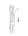
- FIG. 2is an illustration of a mode register of a SDRAM in accordance with one embodiment of the present invention
- FIG. 3is a flow chart illustrating a read transaction
- FIG. 4is a flow chart illustrating a write transaction
- FIG. 5is a illustration of a processor based system with a memory device in accordance with the principles of the present invention.
- the SDRAM 100may be a double data rate or a standard data rate SDRAM.
- the SDRAM 100includes a plurality of control lines 151 .
- Control lines 151may include, for example, well known control signals such as clock signals, column address strobe (CAS) signals, row address strobe (RAS) signals, write enable (WE) signals, etc.
- the control signalsare coupled to the control logic 101 of the SDRAM device. More specifically, the control signals are coupled to a command decoder 102 of the control logic 101 .
- the command decoder 102decodes commands issued by an external memory controller (not illustrated).
- the control logic 101also may include one or more mode registers 103 a .
- the control logic 101may also be coupled to one or more programmable elements such as fuses 103 b .
- the programmable elements 103 bmay instead be a different type of programmable element, such as anti-fuses.
- the SDRAM 100also includes a plurality of address lines 152 , which are coupled to an address register 104 .
- the address register 104latches row and column addresses supplied by on the address lines 152 and provides the addresses to the row address latch and decoder 105 and column address latch and counter 106 , respectively.
- the row address latch and decoder 105latches the row address, then decodes the row address to select a row in memory array 108 .
- the illustrated SDRAM 100contains a single bank of memory implemented as a single memory array 108 , however, it should be understood that the principles of the present invention are applicable to memory devices having multiple arrays and/or multiple banks.
- the column address latch and decoder 106latches a column address and supplies a sequence of one or more column addresses beginning with the latched address to support burst mode reads and writes. That sequence of column addresses is supplied to a column decoder 107 , which, via gating logic 110 selects a column of memory cells in the memory array 108 .
- the sense amplifiers 109are used in conjunction with the gating logic to read or write the memory cells of the memory array 108 .
- the gating logic 110is also coupled, via several circuits to the data lines 153 .
- the datatravels from the gating logic 110 to a read latch 111 .
- the read latch 111is sufficiently large to hold the data associated with the largest supported prefetch mode of the SDRAM 100 .
- a read multiplexer 112is coupled to the read latch 111 to permit a portion of the data stored in the read latch 111 to be outputted via the drivers 113 to the data lines 153 .
- write data from the data lines 153is sent to the receivers 114 to be stored into input register 115 , which are coupled to a write masking logic 116 to supply data to be written to the memory array to the gating logic 110 .
- the input register 115like the read latch 111 , is sufficiently large to hold the data associated with the largest supported prefetch mode of the SDRAM 100 .
- FIG. 1illustrates coupling between the above described circuits using single lines
- the illustrated signal linesare really a plurality of signal lines for conveying a plurality of signals from one circuit to another.
- these signal linesare sufficiently wide to permit the memory device to operate at the largest supported prefetch size.
- the SDRAM 100may support 32-bit words and be operable at 2n- and 4n-prefetch modes.
- the internal data lines and circuitsare sufficiently wide to, for example, permit reading 4 ⁇ 32 or 128 bits of data in a single data transfer period from the memory array 108 .
- the present inventionincludes sufficient circuitry to support the larger prefetch mode (i.e., 4n prefetch in the exemplary embodiment).
- the memory deviceWhen the memory device is configured to operate at the larger prefetch mode the memory device simply accepts or outputs data consistent with the larger prefetch mode.
- the memory deviceWhen the memory device is configured to operate at the smaller prefetch mode (i.e., 2n prefetch in the exemplary embodiment), the memory device masks (i.e., does not output) the portion of data not associated with the selected prefetch mode during reads. Similarly, during writes, the memory device masks out (i.e., does not write) addresses within the memory array which do not correspond to the selected prefetch mode.
- the SDRAM 100may be configured to operate at one of the plurality of supported prefetch modes by programming the one or more mode registers 103 a of the control logic 101 .
- FIG. 2is a more detailed illustration of a mode register 103 a .
- FIG. 2illustrates a 12-bit mode register 103 a , but it should be understood that the mode register 103 a may be one or more mode registers and that the number of bits may be varied.
- bits 0 - 2 of the mode registerare used to encode a burst length
- bit 3is used to store a burst type (i.e., whether burst addresses are sequential or interleaved).
- Bits 4 - 6are conventionally used to encode a CAS latency.
- bits 7 - 11normally encode an operating mode.
- a set of bits from the mode register 103 aare used to encode the prefetch mode.
- the burst length fieldfor example, bits 0 - 2 are utilized to store an encoding of a prefetch mode which the SDRAM 100 will operate at.
- a different group of at least one bitmay be used to encode the prefetch mode.
- one or more of the bits in the operating mode fielde.g., one or more bits from bits 7 - 11
- the mode register fieldsmay be set to a desired value by a memory controller when the memory device is initialized.
- a mode register implementationpermits a system to set the SDRAM 100 to operate at a specific prefetch mode.
- the memory manufacturermay wish to produce a single part which can subsequently be permanently set to one of a plurality of prefetch modes.
- the present inventionmay be practiced via one or more programmable elements, such as fuses 103 b .
- the state of the programmable elementselects a prefetch mode. While FIG. 1 illustrates the programmable element as fuses 103 b , it should be understood that other types of programmable elements, for example, anti-fuses, may be used without departing from the scope of the invention.
- FIG. 3is a flow chart which describes the steps 300 - 311 associated with the read process in accordance with the principles of the present invention.
- the processbegins at step 301 , where the command decoder 102 receives a read command over control lines 151 and the address register 104 receives a column address over address lines 152 . (It is assumed that a row address has been previously latched into the address register 104 through the use of an activate command.)
- the processcontinues at step 302 , where the column address latch and counter 106 receives and latches the column address from the address register 104 .
- the column decoder 107decodes the column address and passes the decoded column address to the gating logic 110 .
- the gating logicreads from the sense amplifiers a plurality of bits required to satisfy the largest prefetch mode supported by the SDRAM 100 .
- the SDRAM 100supports 2n- and 4n-prefetch modes, so four data words of data would be read at step 304 in the exemplary embodiment.
- the datais stored into the read latch 111 .
- the SDRAM 100supports 2n- and 4n-prefetch modes, so regardless of which mode is supported, the SDRAM 100 always outputs at least two words of data per read.
- the control logic 101via signal line 121 causes the read multiplexer 112 to couple the first word of data from the read latch to the drivers 113 to cause the first word of data to appear at the data lines 153 .
- the control logic 101causes the second word of data to be output onto data lines 153 .
- the control logic 101needs to determine whether additional data output is required. If the SDRAM 100 is set to operate at 2n prefetch, the two data words have already been output, therefore the read transaction is completed. However, if the SDRAM 100 is set to operate a 4n prefetch, two more data words must be output before the read is completed. Therefore, at step 308 , the control logic checks to see which prefetch mode is in effect. As previously described, the control logic 101 may examine a field in a mode register 103 a or the states of one or more programmable elements such as fuses 103 b.
- the SDRAM 100is set to operate at 2n prefetch, the read transaction is completed. Therefore, the execution terminates at step 311 . If the SDRAM 100 is set to operate at 4n prefetch, two more data words are required to be output before the read is completed.
- the control logic 101via signal lines 121 causes the read multiplexer 112 to respectively couple the third and fourth words of data from the read latch 111 to the drivers 113 to cause the third and fourth words to be output onto the data lines 153 on successive data transfer periods. At this point, all four data words corresponding to the 4n prefetch mode has been output, so execution terminates at step 311 .
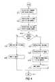
- FIG. 4is a flow chart which describes the steps 400 - 411 associated with the write process in accordance with the principles of the present invention.
- the processbegins at step 401 , where the command decoder 102 receives a write command over control lines 151 and the address register 104 receives a column address over address lines 152 . (It is assumed that a row address has been previously latched into the address register 104 through the use of an activate command.)
- step 402where the column address is latched into the column address latch and counter 106 .
- write data supplied on data lines 153is received by receiver 114 and stored as a first data word in input register 115 .
- the column decoder 107decodes the column address and sends the decoded address to the gating logic 110 . Simultaneously, new write data supplied on data lines 153 is received by the receiver 114 and stored as a second data word in input register 116 .
- the control logicchecks to see which prefetch mode has been set. As noted above, this may include checking a portion of a mode register 103 a or one or more programmable elements such as fuses 103 b.
- step 405the control logic 101 , via signal line 122 , sets the write masking logic to mask the data words not associated the current prefetch mode. In the exemplary embodiment this would corresponds to words 3 and 4 .
- the array 108is written in step 406 . Since words 3 and 4 have been masked by the write masking logic 116 , only words 1 - 2 have been altered in the array. Having written the 2 words associated with the 2n prefetch mode, execution terminates at step 410 .
- step 407(after step 404 ).
- steps 407 - 408the third and fourth data words are received from the data lines 153 and stored as the third and fourth data words, respectively, of the input register 115 .
- the control logicvia signal line 112 , sets the write mask logic 116 to permit all four data words to be written to the memory array 108 (step 409 ).
- FIG. 5illustrates an exemplary processing system 900 which may utilize the memory device 100 of the present invention.
- the processing system 900includes one or more processors 901 coupled to a local bus 904 .
- a memory controller 902 and a primary bus bridge 903are also coupled the local bus 904 .
- the processing system 900may include multiple memory controllers 902 and/or multiple primary bus bridges 903 .
- the memory controller 902 and the primary bus bridge 903may be integrated as a single device 906 .
- the memory controller 902is also coupled to one or more memory buses 907 .
- Each memory busaccepts memory components 908 which include at least one memory device 100 of the present invention.
- the memory components 908may be a memory card or a memory module. Examples of memory modules include single inline memory modules (SIMMs) and dual inline memory modules (DIMMs).
- the memory components 908may include one or more additional devices 909 .
- the additional device 909might be a configuration memory, such as a serial presence detect (SPD) memory.
- the memory controller 902may also be coupled to a cache memory 905 .
- the cache memory 905may be the only cache memory in the processing system.
- processors 901may also include cache memories, which may form a cache hierarchy with cache memory 905 .
- the processing system 900include peripherals or controllers which are bus masters or which support direct memory access (DMA), the memory controller 902 may implement a cache coherency protocol. If the memory controller 902 is coupled to a plurality of memory buses 907 , each memory bus 907 may be operated in parallel, or different address ranges may be mapped to different memory buses 907 .
- DMAdirect memory access
- the primary bus bridge 903is coupled to at least one peripheral bus 910 .
- Various devicessuch as peripherals or additional bus bridges may be coupled to the peripheral bus 910 . These devices may include a storage controller 911 , an miscellaneous I/O device 914 , a secondary bus bridge 915 , a multimedia processor 918 , and an legacy device interface 920 .
- the primary bus bridge 903may also coupled to one or more special purpose high speed ports 922 . In a personal computer, for example, the special purpose port might be the Accelerated Graphics Port (AGP), used to couple a high performance video card to the processing system 900 .
- AGPAccelerated Graphics Port
- the storage controller 911couples one or more storage devices 913 , via a storage bus 912 , to the peripheral bus 910 .
- the storage controller 911may be a SCSI controller and storage devices 913 may be SCSI discs.
- the I/O device 914may be any sort of peripheral.
- the I/O device 914may be an local area network interface, such as an Ethernet card.
- the secondary bus bridgemay be used to interface additional devices via another bus to the processing system.
- the secondary bus bridgemay be an universal serial port (USB) controller used to couple USB devices 917 via to the processing system 900 .
- the multimedia processor 918may be a sound card, a video capture card, or any other type of media interface, which may also be coupled to one additional devices such as speakers 919 .
- the legacy device interface 920is used to couple legacy devices, for example, older styled keyboards and mice, to the processing system 900 .
- FIG. 9illustrates a processing architecture especially suitable for a general purpose computer, such as a personal computer or a workstation, it should be recognized that well known modifications can be made to configure the processing system 900 to become more suitable for use in a variety of applications. For example, in some applications a point-to-point memory architecture may be desirable. Alternatively, many electronic devices which require processing may be implemented using a simpler architecture which relies on a CPU 901 coupled to memory components 908 and/or memory devices 100 .
- These electronic devicesmay include, but are not limited to audio/video processors and recorders, gaming consoles, digital television sets, wired or wireless telephones, navigation devices (including system based on the global positioning system (GPS) and/or inertial navigation), and digital cameras and/or recorders.
- the modificationsmay include, for example, elimination of unnecessary components, addition of specialized devices or circuits, and/or integration of a plurality of devices.
- the present inventionpermits a single memory device to be compatible with at least two prefetch modes.
- the memory devicemay be user programmed to operate at a particular prefetch mode by setting the appropriate field in a mode register 103 a .
- the memory devicemay include manufacturer programmable elements, such as fuses 103 a or anti-fuses, whose state indicate which prefetch mode the memory device will use.
- the present inventioninternally reads data corresponding to the largest supported prefetch size and stores the read data into an internal read latch 111 .
- the read datais then output one word per data transfer period.
- the readcomplete.
- any additional data stored in the internal read latch 111is not outputted.
- the present inventionaccepts write data one word at a time and stores the write data sequentially into different data word positions of an input register 115 .
- the write masking logic 116ensures that only those data locations corresponding to the data words of the current prefetch mode is altered. If not enough data has been received by the current prefetch mode, additional data words are accepted and stored in successive word locations of the input register.
Landscapes
- Engineering & Computer Science (AREA)
- Microelectronics & Electronic Packaging (AREA)
- Computer Hardware Design (AREA)
- Dram (AREA)
Abstract
Description
Claims (90)
Priority Applications (3)
| Application Number | Priority Date | Filing Date | Title |
|---|---|---|---|
| US10/133,386US6895474B2 (en) | 2002-04-29 | 2002-04-29 | Synchronous DRAM with selectable internal prefetch size |
| US10/972,324US6981100B2 (en) | 2002-04-29 | 2004-10-26 | Synchronous DRAM with selectable internal prefetch size |
| US11/268,760US7120754B2 (en) | 2002-04-29 | 2005-11-08 | Synchronous DRAM with selectable internal prefetch size |
Applications Claiming Priority (1)
| Application Number | Priority Date | Filing Date | Title |
|---|---|---|---|
| US10/133,386US6895474B2 (en) | 2002-04-29 | 2002-04-29 | Synchronous DRAM with selectable internal prefetch size |
Related Child Applications (1)
| Application Number | Title | Priority Date | Filing Date |
|---|---|---|---|
| US10/972,324ContinuationUS6981100B2 (en) | 2002-04-29 | 2004-10-26 | Synchronous DRAM with selectable internal prefetch size |
Publications (2)
| Publication Number | Publication Date |
|---|---|
| US20030204674A1 US20030204674A1 (en) | 2003-10-30 |
| US6895474B2true US6895474B2 (en) | 2005-05-17 |
Family
ID=29248970
Family Applications (3)
| Application Number | Title | Priority Date | Filing Date |
|---|---|---|---|
| US10/133,386Expired - LifetimeUS6895474B2 (en) | 2002-04-29 | 2002-04-29 | Synchronous DRAM with selectable internal prefetch size |
| US10/972,324Expired - LifetimeUS6981100B2 (en) | 2002-04-29 | 2004-10-26 | Synchronous DRAM with selectable internal prefetch size |
| US11/268,760Expired - LifetimeUS7120754B2 (en) | 2002-04-29 | 2005-11-08 | Synchronous DRAM with selectable internal prefetch size |
Family Applications After (2)
| Application Number | Title | Priority Date | Filing Date |
|---|---|---|---|
| US10/972,324Expired - LifetimeUS6981100B2 (en) | 2002-04-29 | 2004-10-26 | Synchronous DRAM with selectable internal prefetch size |
| US11/268,760Expired - LifetimeUS7120754B2 (en) | 2002-04-29 | 2005-11-08 | Synchronous DRAM with selectable internal prefetch size |
Country Status (1)
| Country | Link |
|---|---|
| US (3) | US6895474B2 (en) |
Cited By (10)
| Publication number | Priority date | Publication date | Assignee | Title |
|---|---|---|---|---|
| US20050083758A1 (en)* | 2002-04-29 | 2005-04-21 | Ryan Kevin J. | Synchronous DRAM with selectable internal prefetch size |
| US20060117155A1 (en)* | 2004-11-29 | 2006-06-01 | Ware Frederick A | Micro-threaded memory |
| US20070260841A1 (en)* | 2006-05-02 | 2007-11-08 | Hampel Craig E | Memory module with reduced access granularity |
| US20080140974A1 (en)* | 2005-08-01 | 2008-06-12 | Ware Frederick A | Low power memory device |
| US20120191925A1 (en)* | 2011-01-12 | 2012-07-26 | Sony Corporation | Memory access control circuit, prefetch circuit, memory device and information processing system |
| US8432766B2 (en) | 2004-09-30 | 2013-04-30 | Rambus Inc. | Multi-column addressing mode memory system including an integrated circuit memory device |
| US8588017B2 (en) | 2010-10-20 | 2013-11-19 | Samsung Electronics Co., Ltd. | Memory circuits, systems, and modules for performing DRAM refresh operations and methods of operating the same |
| US9268719B2 (en) | 2011-08-05 | 2016-02-23 | Rambus Inc. | Memory signal buffers and modules supporting variable access granularity |
| US9734890B1 (en) | 2016-02-15 | 2017-08-15 | Qualcomm Incorporated | Systems and methods for individually configuring dynamic random access memories sharing a common command access bus |
| US20220075727A1 (en)* | 2019-11-25 | 2022-03-10 | Micron Technology, Inc. | Pre-fetch for memory sub-system with cache |
Families Citing this family (24)
| Publication number | Priority date | Publication date | Assignee | Title |
|---|---|---|---|---|
| US6957308B1 (en)* | 2002-07-11 | 2005-10-18 | Advanced Micro Devices, Inc. | DRAM supporting different burst-length accesses without changing the burst length setting in the mode register |
| KR100666873B1 (en)* | 2003-12-24 | 2007-01-10 | 삼성전자주식회사 | Synchronous DRAM with first dual data rate and second dual data rate |
| KR101001969B1 (en)* | 2003-12-26 | 2010-12-17 | 삼성전자주식회사 | Photosensitive panel and liquid crystal display device having same |
| DE102004024942B3 (en)* | 2004-05-21 | 2005-11-24 | Infineon Technologies Ag | A memory circuit and method for reading out a specific operating information contained in the memory circuit |
| US7287103B2 (en)* | 2005-05-17 | 2007-10-23 | International Business Machines Corporation | Method and apparatus for generating a mask value and command for extreme data rate memories utilizing error correction codes |
| US7613883B2 (en)* | 2006-03-10 | 2009-11-03 | Rambus Inc. | Memory device with mode-selectable prefetch and clock-to-core timing |
| KR100759780B1 (en)* | 2006-09-05 | 2007-09-20 | 삼성전자주식회사 | Semiconductor memory device and data input / output method of semiconductor memory device |
| WO2010116403A1 (en)* | 2009-03-30 | 2010-10-14 | 富士通株式会社 | Prefetch request circuit |
| US9431064B2 (en) | 2012-11-02 | 2016-08-30 | Taiwan Semiconductor Manufacturing Company, Ltd. | Memory circuit and cache circuit configuration |
| KR20140106956A (en)* | 2013-02-27 | 2014-09-04 | 삼성전자주식회사 | Semiconductor memory device for performing a disable operation using anti fuse and method thereof |
| US10846253B2 (en) | 2017-12-21 | 2020-11-24 | Advanced Micro Devices, Inc. | Dynamic page state aware scheduling of read/write burst transactions |
| US10970080B2 (en) | 2018-02-08 | 2021-04-06 | Marvell Asia Pte, Ltd. | Systems and methods for programmable hardware architecture for machine learning |
| US10997510B1 (en) | 2018-05-22 | 2021-05-04 | Marvell Asia Pte, Ltd. | Architecture to support tanh and sigmoid operations for inference acceleration in machine learning |
| US11016801B1 (en) | 2018-05-22 | 2021-05-25 | Marvell Asia Pte, Ltd. | Architecture to support color scheme-based synchronization for machine learning |
| US10891136B1 (en) | 2018-05-22 | 2021-01-12 | Marvell Asia Pte, Ltd. | Data transmission between memory and on chip memory of inference engine for machine learning via a single data gathering instruction |
| US10929760B1 (en) | 2018-05-22 | 2021-02-23 | Marvell Asia Pte, Ltd. | Architecture for table-based mathematical operations for inference acceleration in machine learning |
| US10929779B1 (en) | 2018-05-22 | 2021-02-23 | Marvell Asia Pte, Ltd. | Architecture to support synchronization between core and inference engine for machine learning |
| US10929778B1 (en)* | 2018-05-22 | 2021-02-23 | Marvell Asia Pte, Ltd. | Address interleaving for machine learning |
| TWI703566B (en)* | 2018-08-30 | 2020-09-01 | 大陸商合肥沛睿微電子股份有限公司 | Flash memory controller and associated accessing method and electronic device |
| TWI698874B (en)* | 2018-08-31 | 2020-07-11 | 大陸商合肥沛睿微電子股份有限公司 | Flash memory controller and associated accessing method and electronic device |
| CN110888588B (en)* | 2018-09-07 | 2023-09-01 | 合肥沛睿微电子股份有限公司 | Flash memory controller and related access method and electronic device |
| CN113744774B (en)* | 2021-09-18 | 2024-12-06 | 苏州盛科通信股份有限公司 | Data transmission device, data transmission method and chip |
| US12154634B2 (en)* | 2022-02-18 | 2024-11-26 | Infineon Technologies LLC | Data path circuit and method |
| JP2024102682A (en)* | 2023-01-19 | 2024-07-31 | シャープ株式会社 | Image processing device and image processing method |
Citations (7)
| Publication number | Priority date | Publication date | Assignee | Title |
|---|---|---|---|---|
| US5577224A (en)* | 1994-12-13 | 1996-11-19 | Microsoft Corporation | Method and system for caching data |
| US5890211A (en)* | 1997-05-28 | 1999-03-30 | Western Digital Corporation | Disk drive with cache controlled adaptively for amount of prefetch |
| US6035375A (en)* | 1992-06-04 | 2000-03-07 | Emc Corporation | Cache memory with an allocable micro-cache |
| US6314431B1 (en)* | 1999-09-02 | 2001-11-06 | Hewlett-Packard Company | Method, system, and apparatus to improve instruction pre-fetching on computer systems |
| US6606688B1 (en)* | 1999-08-24 | 2003-08-12 | Hitachi, Ltd. | Cache control method and cache controller |
| US6636945B2 (en)* | 2001-03-29 | 2003-10-21 | Hitachi, Ltd. | Hardware prefetch system based on transfer request address of cache miss load requests |
| US6728839B1 (en)* | 1998-10-28 | 2004-04-27 | Cisco Technology, Inc. | Attribute based memory pre-fetching technique |
Family Cites Families (9)
| Publication number | Priority date | Publication date | Assignee | Title |
|---|---|---|---|---|
| US5305384A (en)* | 1990-12-04 | 1994-04-19 | Chips International, Inc. | Apparatus, system and method for transmitting secure signals over narrow spaced channels |
| US5119403A (en)* | 1991-04-09 | 1992-06-02 | Racal Data Communications Inc. | Superframes |
| US5479475A (en)* | 1993-11-15 | 1995-12-26 | Qualcomm Incorporated | Method and system for providing communication between standard terminal equipment using a remote communication unit |
| US6038310A (en)* | 1994-08-01 | 2000-03-14 | British Telecommunications Public Limited Company | Service node for a telephony network |
| US5778436A (en)* | 1995-03-06 | 1998-07-07 | Duke University | Predictive caching system and method based on memory access which previously followed a cache miss |
| US6138224A (en)* | 1997-04-04 | 2000-10-24 | International Business Machines Corporation | Method for paging software wavetable synthesis samples |
| US6851026B1 (en)* | 2000-07-28 | 2005-02-01 | Micron Technology, Inc. | Synchronous flash memory with concurrent write and read operation |
| US6883044B1 (en)* | 2000-07-28 | 2005-04-19 | Micron Technology, Inc. | Synchronous flash memory with simultaneous access to one or more banks |
| US6895474B2 (en)* | 2002-04-29 | 2005-05-17 | Micron Technology, Inc. | Synchronous DRAM with selectable internal prefetch size |
- 2002
- 2002-04-29USUS10/133,386patent/US6895474B2/ennot_activeExpired - Lifetime
- 2004
- 2004-10-26USUS10/972,324patent/US6981100B2/ennot_activeExpired - Lifetime
- 2005
- 2005-11-08USUS11/268,760patent/US7120754B2/ennot_activeExpired - Lifetime
Patent Citations (8)
| Publication number | Priority date | Publication date | Assignee | Title |
|---|---|---|---|---|
| US6035375A (en)* | 1992-06-04 | 2000-03-07 | Emc Corporation | Cache memory with an allocable micro-cache |
| US5577224A (en)* | 1994-12-13 | 1996-11-19 | Microsoft Corporation | Method and system for caching data |
| US5713003A (en)* | 1994-12-13 | 1998-01-27 | Microsoft Corporation | Method and system for caching data |
| US5890211A (en)* | 1997-05-28 | 1999-03-30 | Western Digital Corporation | Disk drive with cache controlled adaptively for amount of prefetch |
| US6728839B1 (en)* | 1998-10-28 | 2004-04-27 | Cisco Technology, Inc. | Attribute based memory pre-fetching technique |
| US6606688B1 (en)* | 1999-08-24 | 2003-08-12 | Hitachi, Ltd. | Cache control method and cache controller |
| US6314431B1 (en)* | 1999-09-02 | 2001-11-06 | Hewlett-Packard Company | Method, system, and apparatus to improve instruction pre-fetching on computer systems |
| US6636945B2 (en)* | 2001-03-29 | 2003-10-21 | Hitachi, Ltd. | Hardware prefetch system based on transfer request address of cache miss load requests |
Non-Patent Citations (2)
| Title |
|---|
| Chen, "An Effective Programmable Prefetch Engine for On-Chip Caches", (C)1995 IEEE, p. 237-242.** |
| Chiueh, "Sunder: A Programmable Hardware Prefetch Architecture for Numerical Loops", (C)1994, IEEE, p. 488-497.* |
Cited By (31)
| Publication number | Priority date | Publication date | Assignee | Title |
|---|---|---|---|---|
| US6981100B2 (en)* | 2002-04-29 | 2005-12-27 | Micron Technology, Inc. | Synchronous DRAM with selectable internal prefetch size |
| US20050083758A1 (en)* | 2002-04-29 | 2005-04-21 | Ryan Kevin J. | Synchronous DRAM with selectable internal prefetch size |
| US8432766B2 (en) | 2004-09-30 | 2013-04-30 | Rambus Inc. | Multi-column addressing mode memory system including an integrated circuit memory device |
| US8908466B2 (en) | 2004-09-30 | 2014-12-09 | Rambus Inc. | Multi-column addressing mode memory system including an integrated circuit memory device |
| US20060117155A1 (en)* | 2004-11-29 | 2006-06-01 | Ware Frederick A | Micro-threaded memory |
| US20070250677A1 (en)* | 2004-11-29 | 2007-10-25 | Ware Frederick A | Multi-Mode Memory |
| US11797227B2 (en) | 2004-11-29 | 2023-10-24 | Rambus Inc. | Memory controller for micro-threaded memory operations |
| US10331379B2 (en) | 2004-11-29 | 2019-06-25 | Rambus Inc. | Memory controller for micro-threaded memory operations |
| US9652176B2 (en) | 2004-11-29 | 2017-05-16 | Rambus Inc. | Memory controller for micro-threaded memory operations |
| US9292223B2 (en) | 2004-11-29 | 2016-03-22 | Rambus Inc. | Micro-threaded memory |
| US8595459B2 (en) | 2004-11-29 | 2013-11-26 | Rambus Inc. | Micro-threaded memory |
| US7916570B2 (en) | 2005-08-01 | 2011-03-29 | Rambus Inc. | Low power memory device |
| US20100142292A1 (en)* | 2005-08-01 | 2010-06-10 | Ware Frederick A | Low power memory device |
| US20080140974A1 (en)* | 2005-08-01 | 2008-06-12 | Ware Frederick A | Low power memory device |
| US8194493B2 (en) | 2005-08-01 | 2012-06-05 | Rambus, Inc. | Low power memory device |
| US9257159B2 (en) | 2005-08-01 | 2016-02-09 | Rambus Inc. | Low power memory device |
| US10191866B2 (en) | 2006-05-02 | 2019-01-29 | Rambus Inc. | Memory controller for selective rank or subrank access |
| US9256557B2 (en) | 2006-05-02 | 2016-02-09 | Rambus Inc. | Memory controller for selective rank or subrank access |
| US20070260841A1 (en)* | 2006-05-02 | 2007-11-08 | Hampel Craig E | Memory module with reduced access granularity |
| US11467986B2 (en) | 2006-05-02 | 2022-10-11 | Rambus Inc. | Memory controller for selective rank or subrank access |
| US10795834B2 (en) | 2006-05-02 | 2020-10-06 | Rambus Inc. | Memory controller for selective rank or subrank access |
| US8364926B2 (en) | 2006-05-02 | 2013-01-29 | Rambus Inc. | Memory module with reduced access granularity |
| US8588017B2 (en) | 2010-10-20 | 2013-11-19 | Samsung Electronics Co., Ltd. | Memory circuits, systems, and modules for performing DRAM refresh operations and methods of operating the same |
| US20120191925A1 (en)* | 2011-01-12 | 2012-07-26 | Sony Corporation | Memory access control circuit, prefetch circuit, memory device and information processing system |
| US9223704B2 (en)* | 2011-01-12 | 2015-12-29 | Sony Corporation | Memory access control circuit, prefetch circuit, memory device and information processing system |
| US9666250B2 (en) | 2011-08-05 | 2017-05-30 | Rambus Inc. | Memory signal buffers and modules supporting variable access granularity |
| US9268719B2 (en) | 2011-08-05 | 2016-02-23 | Rambus Inc. | Memory signal buffers and modules supporting variable access granularity |
| US9734878B1 (en) | 2016-02-15 | 2017-08-15 | Qualcomm Incorporated | Systems and methods for individually configuring dynamic random access memories sharing a common command access bus |
| US9734890B1 (en) | 2016-02-15 | 2017-08-15 | Qualcomm Incorporated | Systems and methods for individually configuring dynamic random access memories sharing a common command access bus |
| US20220075727A1 (en)* | 2019-11-25 | 2022-03-10 | Micron Technology, Inc. | Pre-fetch for memory sub-system with cache |
| US12007898B2 (en)* | 2019-11-25 | 2024-06-11 | Micron Technology, Inc. | Utilizing a designated memory address to pre-fetch for memory sub-system with cache |
Also Published As
| Publication number | Publication date |
|---|---|
| US20060112231A1 (en) | 2006-05-25 |
| US20050083758A1 (en) | 2005-04-21 |
| US6981100B2 (en) | 2005-12-27 |
| US20030204674A1 (en) | 2003-10-30 |
| US7120754B2 (en) | 2006-10-10 |
Similar Documents
| Publication | Publication Date | Title |
|---|---|---|
| US6895474B2 (en) | Synchronous DRAM with selectable internal prefetch size | |
| US7755968B2 (en) | Integrated circuit memory device having dynamic memory bank count and page size | |
| US6381190B1 (en) | Semiconductor memory device in which use of cache can be selected | |
| JP5399442B2 (en) | Memory transaction burst operation and memory device supporting time multiplexed error correction coding | |
| CN112384977B (en) | Device and method for configurable memory array bank architecture | |
| US8730759B2 (en) | Devices and system providing reduced quantity of interconnections | |
| US6327175B1 (en) | Method and apparatus for controlling a memory array with a programmable register | |
| US20090276548A1 (en) | Dynamically setting burst type of a double data rate memory device | |
| JP4199658B2 (en) | Memory device performing addressing with different burst order in read and write operations | |
| US20210349839A1 (en) | Multi-ported nonvolatile memory device with bank allocation and related systems and methods | |
| US6256240B1 (en) | Semiconductor memory circuit | |
| KR20080014005A (en) | Memory devices and methods with data bypass paths that allow fast testing and calibration | |
| US20030110348A1 (en) | Sequential nibble burst ordering for data | |
| US6888760B2 (en) | System and method for multiplexing data and data masking information on a data bus of a memory device | |
| US6484244B1 (en) | Method and system for storing and processing multiple memory commands | |
| US6542569B2 (en) | Memory device command buffer apparatus and method and memory devices and computer systems using same | |
| US6751130B2 (en) | Integrated memory device, method of operating an integrated memory, and memory system having a plurality of integrated memories | |
| JPH04268288A (en) | Semiconductor memory |
Legal Events
| Date | Code | Title | Description |
|---|---|---|---|
| AS | Assignment | Owner name:MICRON TECHNOLOGY, INC., IDAHO Free format text:ASSIGNMENT OF ASSIGNORS INTEREST;ASSIGNORS:RYAN, KEVIN J.;JOHNSON, CHRISTOPHER S.;REEL/FRAME:012849/0448 Effective date:20020417 | |
| STCF | Information on status: patent grant | Free format text:PATENTED CASE | |
| CC | Certificate of correction | ||
| FEPP | Fee payment procedure | Free format text:PAYOR NUMBER ASSIGNED (ORIGINAL EVENT CODE: ASPN); ENTITY STATUS OF PATENT OWNER: LARGE ENTITY | |
| FPAY | Fee payment | Year of fee payment:4 | |
| AS | Assignment | Owner name:MOSAID TECHNOLOGIES INCORPORATED, CANADA Free format text:ASSIGNMENT OF ASSIGNORS INTEREST;ASSIGNOR:MICRON TECHNOLOGY, INC.;REEL/FRAME:022610/0022 Effective date:20090402 | |
| AS | Assignment | Owner name:ROYAL BANK OF CANADA, CANADA Free format text:U.S. INTELLECTUAL PROPERTY SECURITY AGREEMENT (FOR NON-U.S. GRANTORS) - SHORT FORM;ASSIGNORS:658276 N.B. LTD.;658868 N.B. INC.;MOSAID TECHNOLOGIES INCORPORATED;REEL/FRAME:027512/0196 Effective date:20111223 | |
| FPAY | Fee payment | Year of fee payment:8 | |
| AS | Assignment | Owner name:CONVERSANT INTELLECTUAL PROPERTY MANAGEMENT INC., Free format text:CHANGE OF NAME;ASSIGNOR:MOSAID TECHNOLOGIES INCORPORATED;REEL/FRAME:032439/0638 Effective date:20140101 | |
| AS | Assignment | Owner name:CONVERSANT IP N.B. 276 INC., CANADA Free format text:RELEASE OF SECURITY INTEREST;ASSIGNOR:ROYAL BANK OF CANADA;REEL/FRAME:033484/0344 Effective date:20140611 Owner name:CONVERSANT IP N.B. 868 INC., CANADA Free format text:RELEASE OF SECURITY INTEREST;ASSIGNOR:ROYAL BANK OF CANADA;REEL/FRAME:033484/0344 Effective date:20140611 Owner name:CONVERSANT INTELLECTUAL PROPERTY MANAGEMENT INC., Free format text:RELEASE OF SECURITY INTEREST;ASSIGNOR:ROYAL BANK OF CANADA;REEL/FRAME:033484/0344 Effective date:20140611 | |
| AS | Assignment | Owner name:CONVERSANT INTELLECTUAL PROPERTY MANAGEMENT INC., CANADA Free format text:CHANGE OF ADDRESS;ASSIGNOR:CONVERSANT INTELLECTUAL PROPERTY MANAGEMENT INC.;REEL/FRAME:033678/0096 Effective date:20140820 Owner name:CONVERSANT INTELLECTUAL PROPERTY MANAGEMENT INC., Free format text:CHANGE OF ADDRESS;ASSIGNOR:CONVERSANT INTELLECTUAL PROPERTY MANAGEMENT INC.;REEL/FRAME:033678/0096 Effective date:20140820 | |
| AS | Assignment | Owner name:CPPIB CREDIT INVESTMENTS INC., AS LENDER, CANADA Free format text:U.S. PATENT SECURITY AGREEMENT (FOR NON-U.S. GRANTORS);ASSIGNOR:CONVERSANT INTELLECTUAL PROPERTY MANAGEMENT INC.;REEL/FRAME:033706/0367 Effective date:20140611 Owner name:ROYAL BANK OF CANADA, AS LENDER, CANADA Free format text:U.S. PATENT SECURITY AGREEMENT (FOR NON-U.S. GRANTORS);ASSIGNOR:CONVERSANT INTELLECTUAL PROPERTY MANAGEMENT INC.;REEL/FRAME:033706/0367 Effective date:20140611 | |
| FPAY | Fee payment | Year of fee payment:12 | |
| AS | Assignment | Owner name:CPPIB CREDIT INVESTMENTS, INC., CANADA Free format text:AMENDED AND RESTATED U.S. PATENT SECURITY AGREEMENT (FOR NON-U.S. GRANTORS);ASSIGNOR:CONVERSANT INTELLECTUAL PROPERTY MANAGEMENT INC.;REEL/FRAME:046900/0136 Effective date:20180731 | |
| AS | Assignment | Owner name:CONVERSANT INTELLECTUAL PROPERTY MANAGEMENT INC., CANADA Free format text:RELEASE OF U.S. PATENT AGREEMENT (FOR NON-U.S. GRANTORS);ASSIGNOR:ROYAL BANK OF CANADA, AS LENDER;REEL/FRAME:047645/0424 Effective date:20180731 Owner name:CONVERSANT INTELLECTUAL PROPERTY MANAGEMENT INC., Free format text:RELEASE OF U.S. PATENT AGREEMENT (FOR NON-U.S. GRANTORS);ASSIGNOR:ROYAL BANK OF CANADA, AS LENDER;REEL/FRAME:047645/0424 Effective date:20180731 | |
| AS | Assignment | Owner name:CONVERSANT INTELLECTUAL PROPERTY MANAGEMENT INC., CANADA Free format text:RELEASE BY SECURED PARTY;ASSIGNOR:CPPIB CREDIT INVESTMENTS INC.;REEL/FRAME:054372/0194 Effective date:20201028 | |
| AS | Assignment | Owner name:MOSAID TECHNOLOGIES INCORPORATED, CANADA Free format text:CHANGE OF NAME;ASSIGNOR:CONVERSANT INTELLECTUAL PROPERTY INC.;REEL/FRAME:057448/0207 Effective date:20210401 | |
| AS | Assignment | Owner name:MOSAID TECHNOLOGIES INCORPORATED, CANADA Free format text:CORRECTIVE ASSIGNMENT TO CORRECT THE CONVEYING PARTY'S NAME PREVIOUSLY RECORDED AT REEL: 057448 FRAME: 0207. ASSIGNOR(S) HEREBY CONFIRMS THE CHANGE OF NAME;ASSIGNOR:CONVERSANT INTELLECTUAL PROPERTY MANAGEMENT INC.;REEL/FRAME:064783/0033 Effective date:20210401 |