US6895137B2 - Multi-channel optical coupler for spinning catheter - Google Patents
Multi-channel optical coupler for spinning catheterDownload PDFInfo
- Publication number
- US6895137B2 US6895137B2US10/164,721US16472102AUS6895137B2US 6895137 B2US6895137 B2US 6895137B2US 16472102 AUS16472102 AUS 16472102AUS 6895137 B2US6895137 B2US 6895137B2
- Authority
- US
- United States
- Prior art keywords
- housing
- port
- eccentric
- central
- collection
- Prior art date
- Legal status (The legal status is an assumption and is not a legal conclusion. Google has not performed a legal analysis and makes no representation as to the accuracy of the status listed.)
- Expired - Lifetime, expires
Links
Images


Classifications
- A—HUMAN NECESSITIES
- A61—MEDICAL OR VETERINARY SCIENCE; HYGIENE
- A61B—DIAGNOSIS; SURGERY; IDENTIFICATION
- A61B5/00—Measuring for diagnostic purposes; Identification of persons
- A61B5/0059—Measuring for diagnostic purposes; Identification of persons using light, e.g. diagnosis by transillumination, diascopy, fluorescence
- A61B5/0062—Arrangements for scanning
- A—HUMAN NECESSITIES
- A61—MEDICAL OR VETERINARY SCIENCE; HYGIENE
- A61B—DIAGNOSIS; SURGERY; IDENTIFICATION
- A61B5/00—Measuring for diagnostic purposes; Identification of persons
- A61B5/0059—Measuring for diagnostic purposes; Identification of persons using light, e.g. diagnosis by transillumination, diascopy, fluorescence
- A61B5/0082—Measuring for diagnostic purposes; Identification of persons using light, e.g. diagnosis by transillumination, diascopy, fluorescence adapted for particular medical purposes
- A61B5/0084—Measuring for diagnostic purposes; Identification of persons using light, e.g. diagnosis by transillumination, diascopy, fluorescence adapted for particular medical purposes for introduction into the body, e.g. by catheters
- G—PHYSICS
- G02—OPTICS
- G02B—OPTICAL ELEMENTS, SYSTEMS OR APPARATUS
- G02B6/00—Light guides; Structural details of arrangements comprising light guides and other optical elements, e.g. couplings
- G02B6/24—Coupling light guides
- G02B6/36—Mechanical coupling means
- G02B6/3604—Rotary joints allowing relative rotational movement between opposing fibre or fibre bundle ends
Definitions
- This inventionrelates to catheters, and in particular, to catheters that accommodate more than one optical fiber.
- Vulnerable plaquesare lipid filled cavities that form within the wall of a blood vessel. These plaques, when ruptured, can cause massive clotting in the vessel. The resultant clot can interfere with blood flow to the brain, resulting in a stroke, or with blood flow to the coronary vessels, resulting in a heart attack.
- the catheterincludes a delivery fiber for illuminating a spot on the vessel wall and one or more collection fibers for collecting scattered light from corresponding collection spots on the vessel wall.
- the delivery fiber, and each of the collection fibersform distinct optical channels within the catheter.
- the catheter used for locating plaquesis thus a multi-channel catheter.
- a light source outside the catheterintroduces light into the delivery fiber.
- a detectoralso outside the catheter, detects light in the collection fiber and generates an electrical signal representative of that light. This signal is then digitized and provided to a processor for analysis.
- a vulnerable plaquecan be anywhere within the wall of the artery.
- One way to do thisis to spin the multi-channel catheter about its axis.
- the light source nor the processor spin with the catheterit becomes more difficult to couple light into and out of the delivery and collection fibers while the catheter is spinning.
- the inventionfeatures a multi-channel coupler that spins synchronously with a catheter having optical fibers extending through it. Each fiber defines an optical channel.
- the couplerenables stationary equipment to couple light beams or signals representative of light beams into or out of each fiber separately from all other fibers, even while the catheter spins about its axis.
- the inventionincludes a multi-channel optical coupler having a housing configured to spin about an axis.
- the housinghas a proximal face with a central aperture that intersects the axis.
- the couplerincludes at least two optical relays: a first optical relay that guides the first beam from the central aperture to a central port on the distal face; and a second optical relay for guiding a second beam to a detector from an eccentric port on the distal face.
- Some embodiments of the inventioninclude a first optical relay having a stationary lens disposed to direct the first beam onto the central aperture.
- a focusing lensis disposed between the stationary lens and the central port.
- the first optical relayincludes a graduated index of refraction (“GRIN”) lens seated in the central aperture, the GRIN lens being configured to direct the first beam to the central port.
- GRINgraduated index of refraction
- the inventionincludes embodiments that feature variations of the second optical relay.
- the second optical relayincludes a collimating lens within the housing. This collimating lens is disposed to guide the second beam entering the housing at the eccentric port toward a detector mounted on an inner wall of the housing.
- the second optical relayfurther includes a light-directing element disposed to direct the second beam toward a peripheral wall of the housing.
- second optical relayfeatures one or more eccentric apertures in the proximal face of the housing. These eccentric apertures allow passage of one or more corresponding second beams. These beams trace paths on an annular mirror outside the housing as the housing spins.
- the annular mirrorfeatures a mirror aperture disposed to permit the first beam to pass therethrough. In others, the annular mirror is disposed to direct a path traced by the one or more second beams onto a stationary detector.
- the systemincludes a catheter having a collection fiber and a delivery fiber extending therethrough.
- the catheterengages a distal face of a housing configured to spin about an axis.
- the proximal face of the housinghas a central aperture in optical communication with a central port on the distal face by way of a first optical relay that extends therebetween.
- a second optical relayextending between a detector and an eccentric port on the distal face provides optical communication with the collection fiber.
- the inventionprovides a way to optically couple to a collection fiber and a delivery fiber.
- the methodincludes transmitting a delivery beam into a central aperture of a housing and guiding the delivery beam from the central aperture to a central port in the housing, the central port being in optical communication with the delivery fiber.
- a collection beamis then received from an eccentric port in the housing, the eccentric port being in optical communication with the collection fiber.
- the collection beamis then guided to the detector.
- Embodiments of the inventionmay have one or more of the following advantages.
- the rotary couplerpermits the entire circumference of an artery to be scanned automatically.
- a rotary coupler having the features of the inventioncan also be used to identify other structures outside but near a lumen, or on the surface of the lumen wall.
- cancerous growths within polypscan be identified by a catheter circumferentially scanning the lumen wall of the large intestine
- cancerous tissue in the prostatemay be identified by a catheter scanning the lumen wall of the urethra in the vicinity of the prostate gland
- Barrett's cellscan be identified on the wall of the esophagus.
- the rotary couplercan be used in industrial applications to identify otherwise inaccessible structures outside pipes.
- FIG. 1is a system for identifying vulnerable plaque in a patient.
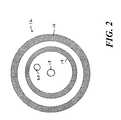
- FIG. 2is a cross-section of the multi-channel catheter in FIG. 1 .
- FIGS. 3 and 5 - 6are multi-channel couplers incorporating the invention.
- FIG. 4is an end view of the multi-channel coupler of FIG. 1 .
- FIG. 1shows a diagnostic system 10 for identifying vulnerable plaque 12 in an arterial wall 14 of a patient.
- the diagnostic systemfeatures a catheter 16 to be inserted into a selected artery, e.g. a coronary artery, of the patient.
- a delivery fiber 18 and a collection fiber 20extend between a distal end 21 and a proximal end 23 of the catheter 16 .
- the catheter 16includes a jacket 17 surrounding a rotatable core 19 .
- the delivery fiber 18extends along the center of the core 19 and the collection fiber 20 extends parallel to, but radially displaced from, the delivery fiber 18 .
- the rotatable core 19spins at rate between approximately 4 revolutions per minute and 30 revolutions per minute.
- a tip assembly 22directs light traveling axially on the delivery fiber 18 toward an illumination spot 24 on the arterial wall 14 .
- the tip assembly 22also collects light from a collection spot 26 on the arterial wall 14 and directs that light into the collection fiber 20 .
- a multi-channel coupler 28 driven by a motor 30engages the proximal end 23 of the catheter 16 .
- the motor 30spins the multi-channel coupler 28 , both the coupler 28 and the catheter 16 spin together as a unit. This feature enables the diagnostic system 10 to circumferentially scan the arterial wall 14 with the illumination spot 24 .
- the multi-channel coupler 28guides light from a laser 32 (or other light source, such as an LED, a super luminescent LED, or an arc lamp) into the delivery fiber 18 and guides light emerging from the collection fiber 20 into one or more detectors (not visible in FIG. 1 ).
- the multi-channel coupler 28performs these tasks even as it spins the catheter 16 .
- the detectorsprovide an electrical signal indicative of light intensity to an amplifier 36 connected to an analog-to-digital (“A/D”) converter 38 .
- the A/D converter 38converts this signal into data that can be analyzed by a processor 40 to identify the presence of a vulnerable plaque 12 hidden beneath the arterial wall 14 .
- a multi-channel coupler 28 for carrying out the foregoing tasksincludes a cylindrical housing 42 having a proximal face 44 joined to a distal face 46 by a peripheral wall 48 .
- a bearing(not shown) supports the housing 42 and enables it to spin about an imaginary axis 50 that intersects the proximal and distal faces 44 , 46 thereof.
- the distal face 46 of the housing 42is coupled to the catheter 16 .
- Two optical fibersextend through the catheter 16 : a delivery fiber 18 for illuminating the arterial wall 14 and a collection fiber 20 that collects light scattered from the arterial wall 14 .
- the catheter 16 and the housing 42spin together about the same axis 50 .
- the distal face 46 of the housing 42has a central port 52 for receiving the delivery fiber 18 and an eccentric port 54 for receiving the collection fiber 20 .
- the central port 52is located at the intersection of the axis 50 with the distal face 46 .
- the eccentric port 54is radially displaced from the central port 52 .
- the proximal face 44has a central aperture 56 for receiving a delivery beam 58 from a laser 32 across a gap 60 .
- the delivery beam 58can be directed toward the central aperture 56 by pointing a laser 32 as shown, by providing an optical relay to direct the delivery beam 58 to the central aperture 58 , or by guiding the delivery beam 58 toward the central aperture 58 along an optical fiber.
- This central aperture 56like the central port 52 on the distal face 46 , remains stationary even as the housing 42 spins about the axis 50 .
- a first collimating lens 62collimates the delivery beam 58 and directs it into the housing 42 through the central aperture 56 .
- a first optical relay 64 within the housing 42then receives the collimated delivery beam 58 and directs it distally across the housing 42 toward the central port 52 , where it enters the delivery fiber 18 .
- an optical relayrefers to a set of optical elements, such as lenses, prisms, and mirrors, arranged to direct light from a source to a destination.
- this first optical relay 64includes a converging lens focused at the central port 28 .
- the first optical relay 64can include components other than, or in addition to that shown in FIG. 1 .
- the delivery beam 58is not constrained to travel along the axis 50 as shown in FIG. 1 .
- a detector 66for receiving a collection beam 68 entering through the eccentric port 54 .
- a second optical relay 70receives the collection beam 68 from the eccentric port 54 and directs it to the detector 66 .
- this second optical relay 70includes a second collimating lens 72 that receives a diverging collection beam 68 from the eccentric port 34 and directs a collimated collection beam 68 toward a diagonal mirror 74 . The diagonal mirror 74 then reflects the collimated collection beam 68 toward the detector 66 .
- the detector 66is electrically connected to a pair of slip rings 76 A-B on the outer surface of the peripheral wall 48 .
- a corresponding pair of stationary brushes 78 A-Bprovides electrical coupling between the slip rings 76 A-B and the amplifier 36 .
- the brushes 78 A-Bmaintain sliding contact with the slip rings, thereby providing a continuous signal to the amplifier 36 .
- the first optical relay 64includes a first GRIN (“graduated index of refraction”) lens seated in the central aperture 56 .
- the second optical relay 70includes a second GRIN lens seated in the eccentric port 54 for directing the collection beam 68 to a detector 66 , now mounted on the inner wall of the proximal face 44 .
- the slip rings 76 A-B in this embodimentare mounted on the outer surface of the proximal face 44 , where they make sliding contact with the brushes 78 A-B as discussed in connection with FIG. 3 .
- the delivery and collection fibers 18 , 20do not actually penetrate the central and eccentric ports 52 , 54 . They are instead held against those ports by a mechanical fitting 80 on the distal face 46 of the housing 42 . This enables the catheter 16 to be easily detached from the multi-channel coupler 28 .
- Various fittings 80are available for mechanically coupling to a fiber. Examples include sub-miniature type A connectors (“SMA”), face contact (“FC”) connectors, and square connectors (“SC”).
- a third embodimentshown in FIG. 6 , dispenses with slip rings 76 A-B and brushes 78 A-B altogether by placing a detector 66 outside the housing 42 .
- the second optical relay 70directs the collection beam 68 to an eccentric aperture 82 on the proximal face 44 of, and radially displaced from, the central aperture 56 .
- the collection beam 68which emerges from the eccentric aperture 82 , traces a circular path similar to that shown in FIG. 4 .
- annular mirror 84 in the gap 60 between the laser 32 and the housing 42intercepts the circular path traced by the collection beam 68 and reflects it toward a detector 66 .
- the annular mirror 84features a central hole 86 aligned with the axis 50 .
- the geometry of the annular mirror 84is selected to encompass the path traced out by the collection beam 68 as the housing 42 spins about the axis 50 .
- the detector 66must likewise have a shape and extent to encompass the path traced out by the collection beam 68 as reflected by the annular mirror 84 .
- the annular mirror 84can be shaped to focus the path traced out on the mirror 84 onto a smaller path on the detector 66 .
- additional optical elementscan be placed in the path followed by the collection beam 68 outside the housing 42 to cause the path traced out by the collection beam 68 to be mapped into another curve.
- the optical couplers shown in FIGS. 1-6are two-channel couplers. Each has a delivery channel that carries the delivery beam 58 and a collection channel for carrying a collection beam 68 . However, additional collection channels can be added by providing additional collection ports, each of which is in communication with an additional collection fiber.
- the second optical relay 64relays scattered light brought to the eccentric port 54 by the collection fiber 20 while the first optical relay 64 delivers light out the central port 52 and into the delivery fiber 18 .
- the collection fiber 20 , the delivery fiber 18 , and the first and second optical relays 64 , 70are all inherently bi-directional.
- the delivery fiber 18 and the first optical relay 64can be used to both deliver light and collect light simultaneously.
- the collection fiber 20 and the second optical relay 64can be used to both deliver and collect light simultaneously.
- the collection fiber 20 and the second optical relay 64can be used to deliver light while the delivery fiber 18 and the first optical relay 64 can be used to collect light.
- the ability of the delivery Fiber 18 and the first optical relay 64 to simultaneously deliver and collect lightpermits the concurrent performance of two or more procedures.
- additional optical relayscan be provided to guide the additional collection beams to corresponding detectors.
- the detectorsare them connected to additional slip rings, which relay a signal to the amplifier by way of additional brushes.
- additional eccentric aperturescan be provided in the proximal face.
- the collection beams emerging from these aperturesform concentric nested traces on the annular mirror.
- the annular mirrorthen reflects these traces to form concentric traces on the detector.
- These tracescan then be separated from each other by designating signals received from selected pixels of the detector to correspond only to particular collection beams.
- the selected pixels on the detectorcorrespond to the loci of the various traces on the detector.
Landscapes
- Health & Medical Sciences (AREA)
- Life Sciences & Earth Sciences (AREA)
- Physics & Mathematics (AREA)
- Medical Informatics (AREA)
- Surgery (AREA)
- Biophysics (AREA)
- Pathology (AREA)
- Engineering & Computer Science (AREA)
- Biomedical Technology (AREA)
- Heart & Thoracic Surgery (AREA)
- Veterinary Medicine (AREA)
- Molecular Biology (AREA)
- Public Health (AREA)
- Animal Behavior & Ethology (AREA)
- General Health & Medical Sciences (AREA)
- Radiology & Medical Imaging (AREA)
- Nuclear Medicine, Radiotherapy & Molecular Imaging (AREA)
- General Physics & Mathematics (AREA)
- Optics & Photonics (AREA)
- Investigating Or Analysing Materials By Optical Means (AREA)
Abstract
Description
Claims (22)
Priority Applications (3)
| Application Number | Priority Date | Filing Date | Title |
|---|---|---|---|
| US10/164,721US6895137B2 (en) | 2002-06-07 | 2002-06-07 | Multi-channel optical coupler for spinning catheter |
| AU2003238919AAU2003238919A1 (en) | 2002-06-07 | 2003-06-06 | Multi-channel optical coupler for spinning catheter |
| PCT/US2003/017832WO2003104864A1 (en) | 2002-06-07 | 2003-06-06 | Multi-channel optical coupler for spinning catheter |
Applications Claiming Priority (1)
| Application Number | Priority Date | Filing Date | Title |
|---|---|---|---|
| US10/164,721US6895137B2 (en) | 2002-06-07 | 2002-06-07 | Multi-channel optical coupler for spinning catheter |
Publications (2)
| Publication Number | Publication Date |
|---|---|
| US20030228085A1 US20030228085A1 (en) | 2003-12-11 |
| US6895137B2true US6895137B2 (en) | 2005-05-17 |
Family
ID=29710270
Family Applications (1)
| Application Number | Title | Priority Date | Filing Date |
|---|---|---|---|
| US10/164,721Expired - LifetimeUS6895137B2 (en) | 2002-06-07 | 2002-06-07 | Multi-channel optical coupler for spinning catheter |
Country Status (3)
| Country | Link |
|---|---|
| US (1) | US6895137B2 (en) |
| AU (1) | AU2003238919A1 (en) |
| WO (1) | WO2003104864A1 (en) |
Cited By (11)
| Publication number | Priority date | Publication date | Assignee | Title |
|---|---|---|---|---|
| US20040111032A1 (en)* | 2002-12-04 | 2004-06-10 | Jeff Korn | Optical coupler for rotating catheter |
| US20040109636A1 (en)* | 2002-12-04 | 2004-06-10 | Jeff Korn | Optical coupler for rotating catheter |
| US20070179487A1 (en)* | 2006-02-01 | 2007-08-02 | The General Hospital Corporation | Apparatus for applying a plurality of electro-magnetic radiations to a sample |
| US20080097158A1 (en)* | 2006-10-20 | 2008-04-24 | Infraredx, Inc. | Noise Suppression System and Method in Catheter Pullback and Rotation System |
| US20080097408A1 (en)* | 2006-10-20 | 2008-04-24 | Infraredx, Inc. | Pullback Carriage Interlock System and Method for Catheter System |
| US20080097223A1 (en)* | 2006-10-20 | 2008-04-24 | Infraredx, Inc. | Optical Catheter Carriage Interlock System and Method |
| US20080097224A1 (en)* | 2006-10-20 | 2008-04-24 | Infraredx, Inc. | Manual and Motor Driven Optical Pullback and Rotation System and Method |
| JP2008154207A (en)* | 2006-09-14 | 2008-07-03 | Victor Co Of Japan Ltd | Rotary joint |
| US8958867B2 (en) | 2011-08-29 | 2015-02-17 | Infraredx, Inc. | Detection of lipid core plaque cap thickness |
| US20190243074A1 (en)* | 2018-02-08 | 2019-08-08 | Canon Usa Inc. | Multiplex Optical Fiber Connector |
| US10776654B2 (en) | 2015-03-10 | 2020-09-15 | Infraredx, Inc. | Assessment of lipid core plaque integrity |
Families Citing this family (3)
| Publication number | Priority date | Publication date | Assignee | Title |
|---|---|---|---|---|
| US7539530B2 (en)* | 2003-08-22 | 2009-05-26 | Infraredx, Inc. | Method and system for spectral examination of vascular walls through blood during cardiac motion |
| WO2005110192A1 (en)* | 2004-05-14 | 2005-11-24 | Olympus Corporation | Insertion device |
| US8123745B2 (en)* | 2007-06-29 | 2012-02-28 | Biosense Webster, Inc. | Ablation catheter with optically transparent, electrically conductive tip |
Citations (18)
| Publication number | Priority date | Publication date | Assignee | Title |
|---|---|---|---|---|
| US4109998A (en)* | 1976-03-04 | 1978-08-29 | The United States Of America As Represented By The Secretary Of The Navy | Optical sliprings |
| US4725116A (en) | 1985-08-14 | 1988-02-16 | Nova Scotia Research Foundation Corp. | Multiple pass optical rotary joint |
| US4872737A (en) | 1988-09-07 | 1989-10-10 | Hitachi Cable Limited | Multi-port fiberoptic rotary joint |
| US4900117A (en) | 1989-02-21 | 1990-02-13 | Chen Linus T | Rotary optical coupler utilizing cylindrical ringshaped mirrors and method of making same |
| US4934783A (en) | 1989-03-08 | 1990-06-19 | Honeywell Inc. | Off-axis fiber optic rotary joint |
| US5016961A (en) | 1989-12-14 | 1991-05-21 | Ampex Corporation | Optical apparatus for electrically inter-coupling rotating and stationary devices |
| US5073040A (en) | 1989-02-09 | 1991-12-17 | Electronique Serge Dassault | Mechano-optical device, in particular a rotary optical joint |
| US5290277A (en) | 1992-04-03 | 1994-03-01 | Angeion Corporation | Multi-fiber linear array laser catheter connector |
| US5297225A (en) | 1992-06-04 | 1994-03-22 | Focal Technologies Incorporated | Off-axis optical rotary joint |
| US5319726A (en) | 1993-09-30 | 1994-06-07 | The United States Of America As Represented By The Secretary Of The Navy | Multi-line passive fiber optic slipring |
| US5336897A (en) | 1992-01-14 | 1994-08-09 | Kabushiki Kaisha Toshiba | Optical data transmission apparatus for transmitting a signal between a rotatable portion and fixed portion of an X-ray CT scanner |
| US5436988A (en) | 1994-01-13 | 1995-07-25 | Mechanical Technology Inc. | Optical slip ring |
| US5535294A (en) | 1995-05-08 | 1996-07-09 | Ceram Optec Industries, Inc. | Connector for multichannel transmission of optical signals through rotating interface |
| US5568578A (en)* | 1994-12-14 | 1996-10-22 | The United States Of America As Represented By The Secretary Of The Navy | Gradient index rod collimation lens devices for enhancing optical fiber line performance where the beam thereof crosses a gap in the line |
| US5872879A (en) | 1996-11-25 | 1999-02-16 | Boston Scientific Corporation | Rotatable connecting optical fibers |
| US6113533A (en) | 1997-12-10 | 2000-09-05 | Transamerica Technologies International | Endoscope video adapter with zoom |
| US6263133B1 (en) | 1999-03-29 | 2001-07-17 | Scimed Life Systems, Inc. | Optical focusing, collimating and coupling systems for use with single mode optical fiber |
| US6301405B1 (en) | 1999-12-20 | 2001-10-09 | The Board Of Trustees Of Western Michigan University | Multi-channel fiber-optic rotary joint |
Family Cites Families (1)
| Publication number | Priority date | Publication date | Assignee | Title |
|---|---|---|---|---|
| US6501551B1 (en)* | 1991-04-29 | 2002-12-31 | Massachusetts Institute Of Technology | Fiber optic imaging endoscope interferometer with at least one faraday rotator |
- 2002
- 2002-06-07USUS10/164,721patent/US6895137B2/ennot_activeExpired - Lifetime
- 2003
- 2003-06-06WOPCT/US2003/017832patent/WO2003104864A1/ennot_activeApplication Discontinuation
- 2003-06-06AUAU2003238919Apatent/AU2003238919A1/ennot_activeAbandoned
Patent Citations (19)
| Publication number | Priority date | Publication date | Assignee | Title |
|---|---|---|---|---|
| US4109998A (en)* | 1976-03-04 | 1978-08-29 | The United States Of America As Represented By The Secretary Of The Navy | Optical sliprings |
| US4725116A (en) | 1985-08-14 | 1988-02-16 | Nova Scotia Research Foundation Corp. | Multiple pass optical rotary joint |
| US4872737A (en) | 1988-09-07 | 1989-10-10 | Hitachi Cable Limited | Multi-port fiberoptic rotary joint |
| US5073040A (en) | 1989-02-09 | 1991-12-17 | Electronique Serge Dassault | Mechano-optical device, in particular a rotary optical joint |
| US4900117A (en) | 1989-02-21 | 1990-02-13 | Chen Linus T | Rotary optical coupler utilizing cylindrical ringshaped mirrors and method of making same |
| US4934783A (en) | 1989-03-08 | 1990-06-19 | Honeywell Inc. | Off-axis fiber optic rotary joint |
| US5016961A (en) | 1989-12-14 | 1991-05-21 | Ampex Corporation | Optical apparatus for electrically inter-coupling rotating and stationary devices |
| US5336897A (en) | 1992-01-14 | 1994-08-09 | Kabushiki Kaisha Toshiba | Optical data transmission apparatus for transmitting a signal between a rotatable portion and fixed portion of an X-ray CT scanner |
| US5290277A (en) | 1992-04-03 | 1994-03-01 | Angeion Corporation | Multi-fiber linear array laser catheter connector |
| US5297225A (en) | 1992-06-04 | 1994-03-22 | Focal Technologies Incorporated | Off-axis optical rotary joint |
| US5319726A (en) | 1993-09-30 | 1994-06-07 | The United States Of America As Represented By The Secretary Of The Navy | Multi-line passive fiber optic slipring |
| US5436988A (en) | 1994-01-13 | 1995-07-25 | Mechanical Technology Inc. | Optical slip ring |
| US5568578A (en)* | 1994-12-14 | 1996-10-22 | The United States Of America As Represented By The Secretary Of The Navy | Gradient index rod collimation lens devices for enhancing optical fiber line performance where the beam thereof crosses a gap in the line |
| US5535294A (en) | 1995-05-08 | 1996-07-09 | Ceram Optec Industries, Inc. | Connector for multichannel transmission of optical signals through rotating interface |
| US5872879A (en) | 1996-11-25 | 1999-02-16 | Boston Scientific Corporation | Rotatable connecting optical fibers |
| US5949929A (en) | 1996-11-25 | 1999-09-07 | Boston Scientific Corporation | Rotatably connecting optical fibers |
| US6113533A (en) | 1997-12-10 | 2000-09-05 | Transamerica Technologies International | Endoscope video adapter with zoom |
| US6263133B1 (en) | 1999-03-29 | 2001-07-17 | Scimed Life Systems, Inc. | Optical focusing, collimating and coupling systems for use with single mode optical fiber |
| US6301405B1 (en) | 1999-12-20 | 2001-10-09 | The Board Of Trustees Of Western Michigan University | Multi-channel fiber-optic rotary joint |
Cited By (17)
| Publication number | Priority date | Publication date | Assignee | Title |
|---|---|---|---|---|
| US20040109636A1 (en)* | 2002-12-04 | 2004-06-10 | Jeff Korn | Optical coupler for rotating catheter |
| US20040111032A1 (en)* | 2002-12-04 | 2004-06-10 | Jeff Korn | Optical coupler for rotating catheter |
| US20100129027A1 (en)* | 2002-12-04 | 2010-05-27 | Infraredx, Inc. | Optical Coupler for Rotating Catheter |
| US7616321B2 (en)* | 2002-12-04 | 2009-11-10 | Infraredx, Inc. | Optical coupler for rotating catheter |
| US20070179487A1 (en)* | 2006-02-01 | 2007-08-02 | The General Hospital Corporation | Apparatus for applying a plurality of electro-magnetic radiations to a sample |
| US9186066B2 (en)* | 2006-02-01 | 2015-11-17 | The General Hospital Corporation | Apparatus for applying a plurality of electro-magnetic radiations to a sample |
| JP2008154207A (en)* | 2006-09-14 | 2008-07-03 | Victor Co Of Japan Ltd | Rotary joint |
| US20080097408A1 (en)* | 2006-10-20 | 2008-04-24 | Infraredx, Inc. | Pullback Carriage Interlock System and Method for Catheter System |
| US20080097224A1 (en)* | 2006-10-20 | 2008-04-24 | Infraredx, Inc. | Manual and Motor Driven Optical Pullback and Rotation System and Method |
| US20080097223A1 (en)* | 2006-10-20 | 2008-04-24 | Infraredx, Inc. | Optical Catheter Carriage Interlock System and Method |
| US20080097158A1 (en)* | 2006-10-20 | 2008-04-24 | Infraredx, Inc. | Noise Suppression System and Method in Catheter Pullback and Rotation System |
| US8958867B2 (en) | 2011-08-29 | 2015-02-17 | Infraredx, Inc. | Detection of lipid core plaque cap thickness |
| US9918643B2 (en) | 2011-08-29 | 2018-03-20 | Infraredx, Inc. | Detection of lipid core plaque cap thickness |
| US10776654B2 (en) | 2015-03-10 | 2020-09-15 | Infraredx, Inc. | Assessment of lipid core plaque integrity |
| US20190243074A1 (en)* | 2018-02-08 | 2019-08-08 | Canon Usa Inc. | Multiplex Optical Fiber Connector |
| US10845549B2 (en)* | 2018-02-08 | 2020-11-24 | Canon U.S.A., Inc. | Multiplex optical fiber connector |
| JP2021525381A (en)* | 2018-02-08 | 2021-09-24 | キヤノン ユーエスエイ, インコーポレイテッドCanon U.S.A., Inc | Multiple fiber optic connector |
Also Published As
| Publication number | Publication date |
|---|---|
| AU2003238919A1 (en) | 2003-12-22 |
| WO2003104864A1 (en) | 2003-12-18 |
| US20030228085A1 (en) | 2003-12-11 |
Similar Documents
| Publication | Publication Date | Title |
|---|---|---|
| US20100129027A1 (en) | Optical Coupler for Rotating Catheter | |
| US6895137B2 (en) | Multi-channel optical coupler for spinning catheter | |
| US7742805B2 (en) | Optical catheter with dual-stage beam redirector | |
| JP4972407B2 (en) | Device for detecting unstable plaque | |
| US6904199B2 (en) | Optical catheter with double-clad fiber | |
| US8280495B2 (en) | Multi-channel catheter tip | |
| US20180035875A1 (en) | Optical Endoluminal Far-Field Microscopic Imaging Catheter | |
| US7996069B2 (en) | Spectroscopy of deeply-scattered light | |
| US20210149101A1 (en) | Multicore Fiber Instrument with 3D-Printed Distal Optics | |
| US6970736B2 (en) | Analysis system of matter adhered to inside wall of vessel | |
| US20040111032A1 (en) | Optical coupler for rotating catheter | |
| CN113288016A (en) | Robot operating system for wound treatment | |
| CN116158720B (en) | Optical-photoacoustic-ultrasonic composite endoscope and endoscope system | |
| CN115568827A (en) | Fluorescence imaging catheter and system based on OCT |
Legal Events
| Date | Code | Title | Description |
|---|---|---|---|
| AS | Assignment | Owner name:INFRAREDX, INC., MASSACHUSETTS Free format text:ASSIGNMENT OF ASSIGNORS INTEREST;ASSIGNORS:ZULUAGA, ANDRES F.;BOUMA, BRETT E.;REEL/FRAME:013409/0074;SIGNING DATES FROM 20020917 TO 20020919 | |
| AS | Assignment | Owner name:MARQUARD, WILLIAM A., KENTUCKY Free format text:SECURITY AGREEMENT;ASSIGNOR:INFRAREDX, INC.;REEL/FRAME:013314/0427 Effective date:20021220 Owner name:PRIEST, WILLIAM W., NEW YORK Free format text:SECURITY AGREEMENT;ASSIGNOR:INFRAREDX, INC.;REEL/FRAME:013314/0427 Effective date:20021220 Owner name:MARQUARD, WILLIAM A.,KENTUCKY Free format text:SECURITY AGREEMENT;ASSIGNOR:INFRAREDX, INC.;REEL/FRAME:013314/0427 Effective date:20021220 Owner name:PRIEST, WILLIAM W.,NEW YORK Free format text:SECURITY AGREEMENT;ASSIGNOR:INFRAREDX, INC.;REEL/FRAME:013314/0427 Effective date:20021220 | |
| AS | Assignment | Owner name:562 MISSION STREET, LLC, CALIFORNIA Free format text:SECURITY AGREEMENT;ASSIGNOR:INFRAREDX, INC.;REEL/FRAME:013401/0001 Effective date:20030131 Owner name:BUTLER, JAMES C., INDIANA Free format text:SECURITY AGREEMENT;ASSIGNOR:INFRAREDX, INC.;REEL/FRAME:013401/0001 Effective date:20030131 Owner name:DATER, ELIZABETH, NEW YORK Free format text:SECURITY AGREEMENT;ASSIGNOR:INFRAREDX, INC.;REEL/FRAME:013401/0001 Effective date:20030131 Owner name:DB SECURITIES INC CUST FBO ALAN J. ZAKON, MARYLAN Free format text:SECURITY AGREEMENT;ASSIGNOR:INFRAREDX, INC.;REEL/FRAME:013401/0001 Effective date:20030131 Owner name:DENNING, RICHARD B., MASSACHUSETTS Free format text:SECURITY AGREEMENT;ASSIGNOR:INFRAREDX, INC.;REEL/FRAME:013401/0001 Effective date:20030131 Owner name:DEWEY JR., ROBERT M., CONNECTICUT Free format text:SECURITY AGREEMENT;ASSIGNOR:INFRAREDX, INC.;REEL/FRAME:013401/0001 Effective date:20030131 Owner name:FLAHERTY, PETER A., NEW YORK Free format text:SECURITY AGREEMENT;ASSIGNOR:INFRAREDX, INC.;REEL/FRAME:013401/0001 Effective date:20030131 Owner name:GLOUTNEY, PIERRE, CANADA Free format text:SECURITY AGREEMENT;ASSIGNOR:INFRAREDX, INC.;REEL/FRAME:013401/0001 Effective date:20030131 Owner name:HOLLAND, WILLIAM, CANADA Free format text:SECURITY AGREEMENT;ASSIGNOR:INFRAREDX, INC.;REEL/FRAME:013401/0001 Effective date:20030131 Owner name:KETTLE FAMILY LIMITED PARTNERSHIP, VIRGINIA Free format text:SECURITY AGREEMENT;ASSIGNOR:INFRAREDX, INC.;REEL/FRAME:013401/0001 Effective date:20030131 Owner name:MARTINELLI, ALFRED, NEW YORK Free format text:SECURITY AGREEMENT;ASSIGNOR:INFRAREDX, INC.;REEL/FRAME:013401/0001 Effective date:20030131 Owner name:MCGARTY, JOHN J., NEW YORK Free format text:SECURITY AGREEMENT;ASSIGNOR:INFRAREDX, INC.;REEL/FRAME:013401/0001 Effective date:20030131 Owner name:OSTERWEIS REVOCABLE TRUST, THE, U/A DATED 9/13/93, Free format text:SECURITY AGREEMENT;ASSIGNOR:INFRAREDX, INC.;REEL/FRAME:013401/0001 Effective date:20030131 Owner name:PAUL F. MULLER LIVING TRUST DATED SEPTEMBER 25, 19 Free format text:SECURITY AGREEMENT;ASSIGNOR:INFRAREDX, INC.;REEL/FRAME:013401/0001 Effective date:20030131 Owner name:PAULI, DAVID C., CANADA Free format text:SECURITY AGREEMENT;ASSIGNOR:INFRAREDX, INC.;REEL/FRAME:013401/0001 Effective date:20030131 Owner name:ROSSTON FAMILY REVOCABLE TRUST, THE, U/A DATED 9/2 Free format text:SECURITY AGREEMENT;ASSIGNOR:INFRAREDX, INC.;REEL/FRAME:013401/0001 Effective date:20030131 Owner name:SILVERSTEIN, MARK AND HEIDI, CONNECTICUT Free format text:SECURITY AGREEMENT;ASSIGNOR:INFRAREDX, INC.;REEL/FRAME:013401/0001 Effective date:20030131 Owner name:SUBRAMANIAM, SOMU, NEW YORK Free format text:SECURITY AGREEMENT;ASSIGNOR:INFRAREDX, INC.;REEL/FRAME:013401/0001 Effective date:20030131 Owner name:WILHELM, LYNN, CANADA Free format text:SECURITY AGREEMENT;ASSIGNOR:INFRAREDX, INC.;REEL/FRAME:013401/0001 Effective date:20030131 Owner name:WOOD, W. DAVID, CANADA Free format text:SECURITY AGREEMENT;ASSIGNOR:INFRAREDX, INC.;REEL/FRAME:013401/0001 Effective date:20030131 Owner name:562 MISSION STREET, LLC,CALIFORNIA Free format text:SECURITY AGREEMENT;ASSIGNOR:INFRAREDX, INC.;REEL/FRAME:013401/0001 Effective date:20030131 Owner name:BUTLER, JAMES C.,INDIANA Free format text:SECURITY AGREEMENT;ASSIGNOR:INFRAREDX, INC.;REEL/FRAME:013401/0001 Effective date:20030131 Owner name:DATER, ELIZABETH,NEW YORK Free format text:SECURITY AGREEMENT;ASSIGNOR:INFRAREDX, INC.;REEL/FRAME:013401/0001 Effective date:20030131 Owner name:DB SECURITIES INC CUST FBO ALAN J. ZAKON,MARYLAND Free format text:SECURITY AGREEMENT;ASSIGNOR:INFRAREDX, INC.;REEL/FRAME:013401/0001 Effective date:20030131 Owner name:DEWEY JR., ROBERT M.,CONNECTICUT Free format text:SECURITY AGREEMENT;ASSIGNOR:INFRAREDX, INC.;REEL/FRAME:013401/0001 Effective date:20030131 Owner name:FLAHERTY, PETER A.,NEW YORK Free format text:SECURITY AGREEMENT;ASSIGNOR:INFRAREDX, INC.;REEL/FRAME:013401/0001 Effective date:20030131 Owner name:MARTINELLI, ALFRED,NEW YORK Free format text:SECURITY AGREEMENT;ASSIGNOR:INFRAREDX, INC.;REEL/FRAME:013401/0001 Effective date:20030131 Owner name:MCGARTY, JOHN J.,NEW YORK Free format text:SECURITY AGREEMENT;ASSIGNOR:INFRAREDX, INC.;REEL/FRAME:013401/0001 Effective date:20030131 Owner name:HOLLAND, WILLIAM,CANADA Free format text:SECURITY AGREEMENT;ASSIGNOR:INFRAREDX, INC.;REEL/FRAME:013401/0001 Effective date:20030131 Owner name:KETTLE FAMILY LIMITED PARTNERSHIP,VIRGINIA Free format text:SECURITY AGREEMENT;ASSIGNOR:INFRAREDX, INC.;REEL/FRAME:013401/0001 Effective date:20030131 Owner name:SUBRAMANIAM, SOMU,NEW YORK Free format text:SECURITY AGREEMENT;ASSIGNOR:INFRAREDX, INC.;REEL/FRAME:013401/0001 Effective date:20030131 Owner name:DENNING, RICHARD B.,MASSACHUSETTS Free format text:SECURITY AGREEMENT;ASSIGNOR:INFRAREDX, INC.;REEL/FRAME:013401/0001 Effective date:20030131 Owner name:GLOUTNEY, PIERRE,CANADA Free format text:SECURITY AGREEMENT;ASSIGNOR:INFRAREDX, INC.;REEL/FRAME:013401/0001 Effective date:20030131 Owner name:PAULI, DAVID C.,CANADA Free format text:SECURITY AGREEMENT;ASSIGNOR:INFRAREDX, INC.;REEL/FRAME:013401/0001 Effective date:20030131 Owner name:SILVERSTEIN, MARK AND HEIDI,CONNECTICUT Free format text:SECURITY AGREEMENT;ASSIGNOR:INFRAREDX, INC.;REEL/FRAME:013401/0001 Effective date:20030131 Owner name:WILHELM, LYNN,CANADA Free format text:SECURITY AGREEMENT;ASSIGNOR:INFRAREDX, INC.;REEL/FRAME:013401/0001 Effective date:20030131 Owner name:WOOD, W. DAVID,CANADA Free format text:SECURITY AGREEMENT;ASSIGNOR:INFRAREDX, INC.;REEL/FRAME:013401/0001 Effective date:20030131 | |
| AS | Assignment | Owner name:INFRAREDX, INC., MASSACHUSETTS Free format text:RELEASE BY SECURED PARTY;ASSIGNORS:MARQUARD, WILLIAM A.;PRIEST, WILLIAM W.;562 MISSION STREET, LLC;AND OTHERS;REEL/FRAME:013901/0706;SIGNING DATES FROM 20030713 TO 20030721 Owner name:INFRAREDX, INC.,MASSACHUSETTS Free format text:RELEASE BY SECURED PARTY;ASSIGNORS:MARQUARD, WILLIAM A.;PRIEST, WILLIAM W.;562 MISSION STREET, LLC;AND OTHERS;SIGNING DATES FROM 20030713 TO 20030721;REEL/FRAME:013901/0706 | |
| STCF | Information on status: patent grant | Free format text:PATENTED CASE | |
| FEPP | Fee payment procedure | Free format text:PAYOR NUMBER ASSIGNED (ORIGINAL EVENT CODE: ASPN); ENTITY STATUS OF PATENT OWNER: LARGE ENTITY | |
| AS | Assignment | Owner name:GENERAL HOSPITAL CORPORATION, THE, MASSACHUSETTS Free format text:LICENSE;ASSIGNOR:INFRAREDX, INC.;REEL/FRAME:020385/0886 Effective date:20071121 | |
| FEPP | Fee payment procedure | Free format text:PAYOR NUMBER ASSIGNED (ORIGINAL EVENT CODE: ASPN); ENTITY STATUS OF PATENT OWNER: LARGE ENTITY Free format text:PAYER NUMBER DE-ASSIGNED (ORIGINAL EVENT CODE: RMPN); ENTITY STATUS OF PATENT OWNER: LARGE ENTITY | |
| FPAY | Fee payment | Year of fee payment:4 | |
| FPAY | Fee payment | Year of fee payment:8 | |
| AS | Assignment | Owner name:GENERAL ELECTRIC CAPITAL CORPORATION, MARYLAND Free format text:SECURITY INTEREST;ASSIGNOR:INFRAREDX, INC.;REEL/FRAME:034290/0344 Effective date:20141112 | |
| FEPP | Fee payment procedure | Free format text:PAYOR NUMBER ASSIGNED (ORIGINAL EVENT CODE: ASPN); ENTITY STATUS OF PATENT OWNER: LARGE ENTITY Free format text:PAYER NUMBER DE-ASSIGNED (ORIGINAL EVENT CODE: RMPN); ENTITY STATUS OF PATENT OWNER: LARGE ENTITY | |
| AS | Assignment | Owner name:NIPRO CORPORATION, JAPAN Free format text:ASSIGNMENT OF ASSIGNORS INTEREST;ASSIGNOR:INFRAREDX, INC.;REEL/FRAME:037013/0099 Effective date:20151021 | |
| AS | Assignment | Owner name:NIPRO CORPORATION, JAPAN Free format text:CORRECTIVE ASSIGNMENT TO CORRECT THE ASSIGNEE'S ADDRESS PREVIOUSLY RECORDED AT REEL: 037013 FRAME: 0099. ASSIGNOR(S) HEREBY CONFIRMS THE ASSIGNMENT;ASSIGNOR:INFRAREDX, INC.;REEL/FRAME:037158/0085 Effective date:20151021 | |
| FEPP | Fee payment procedure | Free format text:PAT HOLDER NO LONGER CLAIMS SMALL ENTITY STATUS, ENTITY STATUS SET TO UNDISCOUNTED (ORIGINAL EVENT CODE: STOL); ENTITY STATUS OF PATENT OWNER: LARGE ENTITY | |
| AS | Assignment | Owner name:INFRAREDX, INC., MASSACHUSETTS Free format text:ASSIGNMENT OF ASSIGNORS INTEREST;ASSIGNOR:NIPRO CORPORATION;REEL/FRAME:039241/0364 Effective date:20160622 | |
| FPAY | Fee payment | Year of fee payment:12 |