US6895034B2 - Ultra-wideband pulse generation system and method - Google Patents
Ultra-wideband pulse generation system and methodDownload PDFInfo
- Publication number
- US6895034B2 US6895034B2US10/188,987US18898702AUS6895034B2US 6895034 B2US6895034 B2US 6895034B2US 18898702 AUS18898702 AUS 18898702AUS 6895034 B2US6895034 B2US 6895034B2
- Authority
- US
- United States
- Prior art keywords
- network
- data
- binary digits
- ultra
- wire
- Prior art date
- Legal status (The legal status is an assumption and is not a legal conclusion. Google has not performed a legal analysis and makes no representation as to the accuracy of the status listed.)
- Expired - Lifetime, expires
Links
- 238000000034methodMethods0.000titleclaimsabstractdescription74
- 239000000835fiberSubstances0.000claimsdescription39
- 238000004891communicationMethods0.000claimsdescription26
- 230000003287optical effectEffects0.000claimsdescription10
- 239000013307optical fiberSubstances0.000claimsdescription5
- 239000004020conductorSubstances0.000claimsdescription4
- 230000005540biological transmissionEffects0.000description24
- 238000005516engineering processMethods0.000description7
- 239000000969carrierSubstances0.000description5
- 230000001413cellular effectEffects0.000description5
- 230000006870functionEffects0.000description5
- 238000001228spectrumMethods0.000description5
- 238000011144upstream manufacturingMethods0.000description5
- 230000002452interceptive effectEffects0.000description4
- 238000013459approachMethods0.000description2
- 238000006243chemical reactionMethods0.000description2
- 238000007726management methodMethods0.000description2
- 238000011084recoveryMethods0.000description2
- 230000000306recurrent effectEffects0.000description2
- 238000005070samplingMethods0.000description2
- 239000007787solidSubstances0.000description2
- 238000007906compressionMethods0.000description1
- 230000006835compressionEffects0.000description1
- 238000002591computed tomographyMethods0.000description1
- 239000012050conventional carrierSubstances0.000description1
- 238000013144data compressionMethods0.000description1
- 238000013500data storageMethods0.000description1
- 230000001419dependent effectEffects0.000description1
- 230000003292diminished effectEffects0.000description1
- 230000003467diminishing effectEffects0.000description1
- 230000000694effectsEffects0.000description1
- 230000005284excitationEffects0.000description1
- 239000011888foilSubstances0.000description1
- 238000012986modificationMethods0.000description1
- 230000004048modificationEffects0.000description1
- 230000010363phase shiftEffects0.000description1
- 229920001690polydopaminePolymers0.000description1
- 230000004044responseEffects0.000description1
- 238000007493shaping processMethods0.000description1
- 230000008054signal transmissionEffects0.000description1
- 230000005236sound signalEffects0.000description1
- 230000003595spectral effectEffects0.000description1
- 239000003381stabilizerSubstances0.000description1
- 230000003068static effectEffects0.000description1
Images


Classifications
- H—ELECTRICITY
- H04—ELECTRIC COMMUNICATION TECHNIQUE
- H04B—TRANSMISSION
- H04B1/00—Details of transmission systems, not covered by a single one of groups H04B3/00 - H04B13/00; Details of transmission systems not characterised by the medium used for transmission
- H04B1/69—Spread spectrum techniques
- H04B1/7163—Spread spectrum techniques using impulse radio
- H04B1/7176—Data mapping, e.g. modulation
- H—ELECTRICITY
- H04—ELECTRIC COMMUNICATION TECHNIQUE
- H04L—TRANSMISSION OF DIGITAL INFORMATION, e.g. TELEGRAPHIC COMMUNICATION
- H04L25/00—Baseband systems
- H04L25/38—Synchronous or start-stop systems, e.g. for Baudot code
- H04L25/40—Transmitting circuits; Receiving circuits
- H04L25/49—Transmitting circuits; Receiving circuits using code conversion at the transmitter; using predistortion; using insertion of idle bits for obtaining a desired frequency spectrum; using three or more amplitude levels ; Baseband coding techniques specific to data transmission systems
- H04L25/4902—Pulse width modulation; Pulse position modulation
Definitions
- the present inventiongenerally relates to ultra-wideband communications. More particularly, the invention concerns a method to generate ultra-wideband pulses that convey data through a wire medium.
- the Information Ageis upon us. Access to vast quantities of information through a variety of different communication systems are changing the way people work, entertain themselves, and communicate with each other. For example, as a result of increased telecommunications competition mapped out by Congress in the 1996 Telecommunications Reform Act, traditional cable television program providers have evolved into full-service providers of advanced video, voice and data services for homes and businesses. A number of competing cable companies now offer cable systems that deliver all of the just-described services via a single broadband network.
- the present inventionprovides a method to transmit ultra-wideband signals across any wire medium, whether the medium is twisted-pair wire, coaxial cable, fiber optic cable, or other types of wire media.
- a method of transmitting an ultra-wideband signal through a wire mediumcomprises generating an ultra-wideband pulse, the ultra-wideband pulse including a first section representing a first data symbol, and a second section representing a second data symbol.
- Another embodiment of the present inventioncomprises a method of transmitting an ultra-wideband signal through a wire medium that includes an ultra-wideband pulse structured to transmit data through a wire medium, with the ultra-wideband pulse comprising an amplitude that represents a first data symbol.
- the ultra-wideband pulsealso includes a plurality of time bins, with each time bin representing a second data symbol. This embodiment ultra-wideband signal thus transmits two distinct data symbols, increasing the bandwidth of the wire media.
- an ultra-wideband signalcan be transmitted simultaneously with a traditional cable television signal, Internet connection signal or voice transmission signal. Because the ultra-wideband signal can be transmitted substantially simultaneously with the other signals, the overall bandwidth or capability of the system to transmit data is vastly increased.
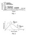
- FIG. 1is an illustration of different communication methods
- FIG. 2is an illustration of two ultra-wideband pulses
- FIG. 3is a schematic illustration of one embodiment of an ultra-wideband communication system employing a wire medium
- FIG. 4is a schematic illustration of a second embodiment of an ultra-wideband communication system employing a wire medium
- FIG. 5is an illustration of exemplary ultra-wideband pulses constructed according to the present invention.
- FIG. 6is an illustration of a single ultra-wideband pulse as shown in FIG. 5 ;
- FIGS. 7 a - 7 hillustrate rectangular coordinate representations of data bits
- FIGS. 8 a - 8 hillustrate ultra-wideband pulses constructed according to an alternative embodiment of the present invention, with corresponding ultra-wideband pulses constructed to transmit corresponding data bit representations, as illustrated in FIGS. 7 a - 7 h.
- a traditional cable television provider, a community antenna television provider, a community access television provider, a cable television provider, a hybrid fiber-coax television provider, an Internet service provider, or any other provider of television, audio, voice and/or Internet datareceives broadcast signals at a central station, either from terrestrial cables, and/or from one or more antennas that receive signals from a communications satellite.
- the broadcast signalsare then distributed, usually by coaxial and/or fiber optic cable, from the central station to nodes located in business or residential areas.
- CATVcommunity access television provider
- HFCSHybrid Fiber-Coax Systems
- the analog coax systemsare typically characterized as pure analog systems. Pure analog CATV systems are characterized by their use of established NTSC/PAL (National Television Standards Committee/Phase Alternation Line) modulation onto a frequency carrier at 6 or 8 MHz intervals.
- NTSC/PALNational Television Standards Committee/Phase Alternation Line
- HFCSis a combination analog—digital topology employing both coaxial (analog) and fiber optic (digital) media that typically supports digitally modulated/encoded television channels above channel 78 .
- the analog channelsare modulated in 6 MHz allocations on channels 2 to 78 using frequencies from 55 to 547 MHz.
- digital channelstypically start at channel 79 and go as high as 136 and occupy a frequency range from 553 to 865 MHz.
- channel assignmentscan go as high as channel 158 or 997 MHz.
- the current ANSI/EIA-542-1997 standardonly defines and assigns channels to these limits.
- the actual wire/cable media itselfis generally capable of transmitting frequencies up to 3 GHz.
- the satellite downlinkIn both CATV and HFCS systems, typically the satellite downlink enters the cable company's head-end and the video, and/or other data streams are de-multiplexed out. Individual video data streams (either NTSC, MPEG, or any other suitable protocol) are extracted from the satellite downlink stream and routed to modulators specific for individual television channels. The outputs from each modulator are then combined into one broadband signal. From this point the combined channels are amplified and sent out, either by coaxial or fiber optic cable, to the customers.
- Individual video data streamsare extracted from the satellite downlink stream and routed to modulators specific for individual television channels.
- modulatorsspecific for individual television channels.
- the outputs from each modulatorare then combined into one broadband signal. From this point the combined channels are amplified and sent out, either by coaxial or fiber optic cable, to the customers.
- the broadband signalis modulated onto a fiber optic cable for distribution into the field, such as residential neighborhoods, or business districts.
- Modulation of the broadband signalis typically accomplished in one of two ways.
- the first methodthe entire broadband signal is sampled and digitized using a high speed Analog to Digital Converter (ADC).
- ADCAnalog to Digital Converter
- the datamust be sampled at a rate at least twice the highest frequency component to meet Nyquist minimum sampling requirements.
- the signalshould be sampled at 2.5 to 4 times the highest frequency, which entails sample rates of approximately 2 to 4 GHz.
- a parallel to serial converterthen shifts the parallel output data of the ADC into a serial format.
- the serial datadrives a laser diode for transmission over the fiber optic cable.
- the second methodis broadband block conversion where the entire spectrum of the broadband signal is modulated onto the fiber optic cable.
- Designated access nodesare located in neighborhoods, business districts and other areas.
- the access nodescontain a high speed Digital to Analog Converter (DAC) and a de-serializer.
- a fiber optic receiverdetects the laser-modulated signal at the access node.
- a parallel to serial converterde-serializes the data and it is feed to the high speed DAC.
- the datathen leaves the access node on standard 75 ohm, RG-6 or RG-8 or other suitable coax cable and is distributed to the customer's premises.
- the broadband signalis extracted from the fiber optic cable and transferred to a coaxial cable that connects to individual homes, apartments, businesses, universities, and other customers.
- the digital channels that generally reside on CATV channels 79 and higherare fundamentally different than the analog channels that generally reside on channels 2 through 78 .
- the analog channelsare comprised of modulated frequency carriers.
- the digital channelswhich generally use the 6 MHz allocation system, are digitally modulated using Quadrature Amplitude Modulation (QAM).
- QAMis a method of combining two amplitude modulated signals into a single channel, thereby doubling the effective bandwidth.
- In a QAM signalthere are two carriers, each having the same frequency but differing in phase by 90 degrees.
- the two modulated carriersare combined for transmission, and separated after transmission.
- QAM 16transmits 16 bits per signal, QAM 32 , 64 , and 256 each transmit 32, 54 and 256 bits per signal, respectively.
- QAMwas developed to support additional video streams encoded with MPEG video compression.
- Conventional CATV and HFCS networksmay employ QAM levels up to QAM 64 to enable up to 8 independent, substantially simultaneous MPEG video streams to be transmitted.
- the coaxial cableis connected to either a set-top box or directly to a television.
- the receiving devicethen de-multiplexes and de-modulates the video, audio, voice, Internet or other data.
- a televisioncan directly receive the analog signal, a set-top box is generally required for reception of the digitally encoded channels residing on CATV channels 79 and higher.
- the conventional wisdom for overcoming this limitationis to boost the power (i.e., increase the voltage of the signal) at the transmitter to boost the voltage level of the signal relative to the noise at the receiver. Without boosting the power at the transmitter, the receiver is unable to separate the noise from the desired signal. Thus, the overall performance of wire media systems is still significantly limited by the accompanying noise that is inherent in wire media.
- the present inventionmay be employed in any type of network that uses wire media, in whole, or in part. That is, a network may use both wire media, such as coaxial cable, and wireless devices, such as satellites.
- a networkis a group of points or nodes connected by communication paths. The communication paths may be connected by wires, or they may be wirelessly connected.
- a network as defined hereincan interconnect with other networks and contain subnetworks.
- a network as defined hereincan be characterized in terms of a spatial distance, for example, such as a local area network (LAN), a personal area network (PAN), a metropolitan area network (MAN), and a wide area network (WAN), among others.
- LANlocal area network
- PANpersonal area network
- MANmetropolitan area network
- WANwide area network
- a network as defined hereincan also be characterized by the type of data transmission technology in use on it, for example, a TCP/IP network, and a Systems Network Architecture network, among others.
- a network as defined hereincan also be characterized by whether it carries voice, data, or both kinds of signals.
- a network as defined hereincan also be characterized by who can use the network, for example, a public switched telephone network (PSTN), other types of public networks, and a private network (such as within a single room or home), among others.
- PSTNpublic switched telephone network
- a network as defined hereincan also be characterized by the usual nature of its connections, for example, a dial-up network, a switched network, a dedicated network, and a nonswitched network, among others.
- a network as defined hereincan also be characterized by the types of physical links that it employs, for example, optical fiber, coaxial cable, a mix of both, unshielded twisted pair, and shielded twisted pair, among others.
- the present inventionemploys a “carrier free” architecture, which does not require the use of high frequency carrier generation hardware, carrier modulation hardware, stabilizers, frequency and phase discrimination hardware or other devices employed in conventional frequency domain communication systems.
- the present inventiondramatically increases the bandwidth of conventional networks that employ wire media, but can be inexpensively deployed without extensive modification to the existing wire media network.
- the present inventionprovides increased bandwidth by injecting, or otherwise super-imposing an ultra-wideband (UWB) signal into the existing data signal and subsequently recovers the UWB signal at an end node, set-top box, subscriber gateway, or other suitable location.
- Ultra-wideband, or impulse radioemploys pulses of electromagnetic energy that are emitted at nanosecond or picosecond intervals (generally tens of picoseconds to a few nanoseconds in duration). For this reason, ultra-wideband is often called “impulse radio.” Because the excitation pulse is not a modulated waveform, UWB has also been termed “carrier-free” in that no apparent carrier frequency is evident in the radio frequency (RF) spectrum. That is, the UWB pulses are transmitted without modulation onto a sine wave carrier frequency, in contrast with conventional radio frequency technology. Ultra-wideband generally requires neither an assigned frequency nor a power amplifier.
- Conventional radio frequency technologyemploys continuous sine waves that are transmitted with data embedded in the modulation of the sine waves' amplitude or frequency.
- a conventional cellular phonemust operate at a particular frequency band of a particular width in the total frequency spectrum.
- the Federal Communications Commissionhas allocated cellular phone communications in the 800 to 900 MHz band.
- Cellular phone operatorsuse 25 MHz of the allocated band to transmit cellular phone signals, and another 25 MHz of the allocated band to receive cellular phone signals.
- FIG. 1Another example of a conventional radio frequency technology is illustrated in FIG. 1.
- 802.11aa wireless local area network (LAN) protocol, transmits radio frequency signals at a 5 GHz center frequency, with a radio frequency spread of about 5 MHz.
- LANlocal area network
- a UWB pulsemay have a 1.8 GHz center frequency, with a frequency spread of approximately 4 GHz, as shown in FIG. 2 , which illustrates two typical UWB pulses.
- FIG. 2illustrates that the narrower the UWB pulse in time, the higher its center frequency and the broader the spread of its frequency spectrum. This is because frequency is inversely proportional to the time duration of the pulse.
- a 600 picosecond UWB pulsewill have about a 1.8 GHz center frequency, with a frequency spread of approximately 4 GHz.
- a 300 picosecond UWB pulsewill have about a 3 GHz center frequency, with a frequency spread of approximately 8 GHz.
- UWB pulsesgenerally do not operate within a specific frequency, as shown in FIG. 1 .
- UWB communication systemsallow communications at very high data rates, such as 100 megabits per second or greater.
- the UWB pulseis spread across an extremely wide frequency range, the power sampled at a single, or specific frequency is very low. For example, a UWB one-watt signal of one nano-second duration spreads the one-watt over the entire frequency occupied by the pulse.
- the UWB pulse power presentis one nano-watt (for a frequency band of 1 GHz). This is well within the noise floor of any wire media system and therefore does not interfere with the demodulation and recovery of the original CATV signals.
- the multiplicity of UWB pulsesare transmitted at relatively low power (when sampled at a single, or specific frequency), for example, at less than ⁇ 30 power decibels to ⁇ 60 power decibels, which minimizes interference with conventional radio frequencies.
- UWB pulses transmitted through most wire mediawill not interfere with wireless radio frequency transmissions. Therefore, the power (sampled at a single frequency) of UWB pulses transmitted though wire media may range from about +30 dBm to about ⁇ 90 dBm.
- a CATV systemgenerally employs a coaxial cable that transmits analog data on a frequency carrier.
- AMamplitude modulation
- QAMquadrature modulation
- UWB signalscan coexist in this environment without interference.
- AMthe data signal M(t) is multiplied with a cosine at the carrier frequency.
- an “in phase” and “quadrature” carrierscan carry data signals Mc(t) and Ms(t).
- an UWB systemtransmits a narrow time domain pulse, and the signal power is generally evenly spread over the entire bandwidth occupied by the signal.
- the UWB pulse power presentis one nano-watt (for a frequency band of 1 GHz). This is well within the noise floor of any wire media system and therefore does not interfere with the demodulation and recovery of the original AM or QAM data signals.
- Wire media communication systemssuffer from performance limitations caused by signal interference, ambient noise, and spurious noise. These limitations affect the available bandwidth, distance, and carrying capacity of the wire media system. With wired communication systems, the noise floor and signal interference in the wire media rapidly overcome the transmitted carrier signal. This noise on the wire media is a significant limitation to the ability of the system to increase bandwidth. UWB technology makes use of the noise floor to transmit data, without interfering with the carrier signal. Moreover, UWB transmitted through a wire medium has distinct advantages over its use in a wireless environment. In a wire environment there are no concerns with intersymbol interference, and there are no concerns relating to multi-user interference.
- CATV channelstypically occupy 6 MHz in the US and 8 MHz in Europe. These channels are arranged in a re-occurring pattern beginning at approximately 50 MHz and dependent on the CATV system, extend upward to 550 MHz, 750 MHz, 870 MHz, 1 GHz and higher.
- the present inventionis capable of injecting UWB pulses into the existing CATV infrastructure. These UWB signals do not interfere or degrade existing frequency domain signals. Additionally, the UWB signals can carry vast amounts of information with digital meaning in the time domain.
- the present inventionprovides an apparatus and method to enable any wire media network to augment their available bandwidth.
- this additional bandwidthis obtained by introducing UWB signals into the existing data transmission chain prior to broadcast from the system operator's head-end.
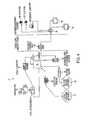
- the head-endmay include several components, such as the antenna farm 15 , the satellite receivers 20 , the channel modulator 25 , the combiner 30 , and the fiber optic transmitter/receiver 35 .
- UWB signalsmay be introduced into the wire media network at other locations, such as at the Internet router 90 or at the host digital terminal 80 , or at any other suitable location.
- the present inventionprovides UWB communication across fiber optic and coaxial cable, twisted pair wires, or any other type of conductive wire.
- a wire media networkwill be able to both transmit and receive digital information for the purposes of telephony, high-speed data, video distribution, video conferencing, wireless base operations and other similar purposes.
- the wired ultra-wideband communication system 10is configured to transmit ultra-wideband signals over an existing network or system that includes wire media.
- the wired ultra-wideband (UWB) system 10may transmit UWB signals over an existing community access television network (CATV), an optical network, a cable television network, a community antenna television network, a hybrid fiber-coax television network, an Internet service provider network, a PSTN network, a WAN, LAN, MAN, PAN, TCP/EP network, a college campus, town, city, or any other type of network as defined above, that employs wire media, in whole or in part.
- CATVcommunity access television network
- an optical networkan optical network
- cable television network
- a community antenna television networka hybrid fiber-coax television network
- an Internet service provider networka PSTN network
- WANwide area network
- LANlocal area network
- MANpersonal area network
- PANpersonal area network
- TCP/EP networka college campus, town, city, or any other type of
- An antenna farm 15receives audio, video and data information from one or more satellites (not shown). Additional data may be received by terrestrial cables and wires and by terrestrial wireless sources, such as a multichannel multipoint distribution service (MMDS). The data is then forwarded to the satellite receivers 20 that demodulate the data into separate audio, video and data streams. This information is forwarded to the channel modulators 25 that receive the program signals, such as CNN or MTV. The channel modulators 25 mix each signal with a radio frequency (RF) and assign a station number (such as 2 to 99) that each program will be received on by subscribers.
- RFradio frequency
- the multiple RF signalsare then forwarded to a combiner 30 that combines the multiple signals into a single output. That is, the combiner 30 receives the program signals from the channel modulators 25 and combines them onto a single coax cable and forwards the signal to the fiber optic transmitter/receiver 35 .
- the above-described arrangement and function of channel modulators 25 and combiners 30may vary with each type of wire media network.
- Additional audio, video, or other data signals received from either the antenna farm 15 or from terrestrial sources such as fiber optic or coaxial cablescan be routed from the satellite receiver 20 to the service provider ultra-wideband (UWB) device 40 .
- the service provider UWB device 40converts the audio, video, or other data signals received from the satellite receiver 20 into a multiplicity of UWB electromagnetic pulses.
- One embodiment of the service provider UWB device 40may function as a transmitter and as a receiver, to both transmit and receive UWB pulses.
- the service provider UWB device 40may include several components, including a controller, digital signal processor, an analog coder/decoder, a waveform generator, an encoder, static and dynamic memory, data storage devices, a receiver, an amplifier, an interface, one or more devices for data access management, and associated cabling and electronics.
- a controllermay include error control, and data compression functions.
- the analog coder/decodermay include an analog to digital conversion function and vice versa.
- the data access management device or devicesmay include various interface functions for interfacing to wire media such as phone lines and coaxial cables.
- Alternative embodiments of the UWB device 40may employ hard-wired circuitry used in place of, or in combination with software instructions. Thus, embodiments of the UWB device 40 are not limited to any specific combination of hardware or software.
- the digital signal processor in the service provider UWB device 40modulates the audio, video, or other data signals received from the satellite receiver 20 into a multiplicity of UWB electromagnetic pulses, and may also demodulate UWB pulses received from the subscriber.
- modulationis the specific technique used to encode the audio, video, or other data into a multiplicity of UWB pulses. Because UWB does not use a conventional carrier wave, the transmitted pulses, or waveforms themselves must contain the information being communicated. That is, the UWB pulses themselves contain the desired information.
- the digital signal processor and/or waveform generatormay modulate the received audio, video, or other data signals into a multiplicity of UWB pulses that may have a duration that may range between about 0.1 nanoseconds to about 100 nanoseconds, and may be transmitted at relatively low power, for example, at less than ⁇ 10 power decibels to ⁇ 60 power decibels, as measured at a single frequency.
- the UWB pulse duration and transmitted powermay vary, depending on several factors. Different modulation techniques employ different UWB pulse timing, durations and power levels.
- BPSKBinary Phase-Shift Keying
- FIGS. 5-6illustrate three types of modulation techniques employed by the present invention: pulse amplitude modulation (PAM), pulse position modulation (PPM), and a combined form of PAM and PPM, which will be called PQAM.
- FIG. 5illustrates several UWB pulses 105 .
- PAMencodes or designates data in the amplitude of the UWB pulse.
- each UWB pulse 105may have a specific amplitude, or height 115 .
- the amplitude 115 of each UWB pulse 105can designate, or represent a specific bit value.
- the amplitude 115 of an UWB pulse 105may be varied by specific increments with each increment designating a different bit value.
- the UWB pulse 105has 16 discrete amplitudes 115 .
- the first discrete amplitude 115designates a bit value of 0000, with the second discrete amplitude 115 designating a bit value of 0001, and the third discrete amplitude 115 designating a bit value of 0010.
- the bit valuemay vary.
- each specific amplitude 115 of the UWB pulse 105may designate 3 bits, 4 bits (shown in FIG. 6 ), 8, 16, 32, 64, 128, 256 or 512 discrete bits.
- an UWB pulse trainmay include a multiplicity of pulses, with each pulse having a different amplitude 115 , representing a different bit value, as shown in FIG. 5 .
- the number of discrete amplitudes 115may vary. For example, one embodiment of the present invention may employ 32 different amplitudes 115 . If 5 bits were encoded in each pulse, then a PAM 32 modulation method would allow 100 million pulses, or symbols per second to carry 500 million bits per second. This number can be realized because in an average UWB pulse recurrent frequency of 100 Mhz there are 100 million symbols transmitted per second. If each symbol carries 5 bits, 500 million bits per second can be transmitted.
- FIG. 6An alternative modulation technique, of pulse position modulation (PPM) constructed according to the present invention for transmitting UWB pulses through a wire medium is also illustrated in FIG. 6 .
- Each UWB pulse 105is divided into discrete time bins 110 .
- FIG. 6illustrates a UWB pulse 105 that includes 16 discrete time bins 110 .
- Each time bin 110represents a specific bit value. For example, as illustrated, a first time bin 110 may represent a bit value of 0000 and an adjacent time bin 110 may represent a bit value of 0001.
- the UWB pulse 105is received at a UWB receiver, the pulse is sampled at a designated time bin 110 and the representative bit value is obtained.
- a representation of any number of bitscan be transmitted with each UWB pulse 105 .
- a specific time binmay represent 3, 4, 8, 16, 32, 64, 128, 256 or more bits.
- the above-described PPM method transmitting 4 bits per pulsewould carry 400 million bits per second, with a UWB pulse rate of 100 MHz.
- Alternative embodiments of the present inventionmay employ more, or less than 16 discrete time bins 110 .
- the number of time binsmay range from 3 to 256 or more time bins 110 .
- PQAMconstructed according to the present invention.
- This alternative modulation schemecomprises a UWB pulse 105 that is modulated to include specific time bins 110 as well as specific amplitudes 115 .
- This modulation schemeallows the transmission of a bit value that represents twice the number of bits than some of the above-described modulation methods.
- PPMdetected arrival time
- PAMdetected amplitude
- PQAMcan carry 8 bits of information per pulse, when PPM and PAM are each transmitting 4 bits.
- PQAMis capable of transmitting 800 million bits per second, with a UWB pulse transmission rate of 100 MHz.
- PQAMincludes a time bin value 110 as well as a pulse amplitude 115 value.
- an UWB receiverwill receive a UWB pulse 105 and obtain a bit value assigned to a specific time bin 110 as well as a bit value assigned to a specific amplitude 115 .
- inter-pulse location 120includes a time bin 110 bit value of 1001 and an amplitude 115 bit value of 0001. Therefore, a representation, or symbol corresponding to 8 bits (10010001) is transmitted by a single UWB pulse 105 .
- Alternative UWB pulses 105 employing this modulation methodmay transmit a symbol or representation that corresponds to 16, 32, 64, 128, 256 or more bits in a single UWB pulse 105 .
- FIGS. 7 a - 7 h and 8 a - 8 hillustrate rectangular coordinate representations of different data bits, or data bit symbols 125 .
- Each circlerepresents a specific bit value.
- symbol 125 arepresents a bit value of 010101.
- This bit valueis determined by combining the bit value assigned to the X-axis as well as the Y-axis for each circle.
- the circle located in the lower left corner of the -X and -Y regionhas a bit value of 000.
- the adjacent circleis assigned a bit value of 001 and the circle adjacent to that one along the same row is designated 010.
- bit valuesuses the conventional binary numbering system. Referring again to FIGS. 7 a - 7 h , only three bits are assigned to each axis and therefore the bit value for symbol 125 b is 111111, the bit value for symbol 125 c is 010101, the bit value for symbol 125 d is 100101, the bit value for symbol 125 e is 000001, the bit value for symbol 125 f is 000110, the bit value for symbol 125 g is 011011, and the bit value for symbol 125 h is 000100.
- Alternative embodiments of the present inventionmay assign 4, 8, 16, 32, 128, 256 or 512 bits to each circle on each axis of the rectangular coordinate representation. For example, if 16 bits are assigned to each location on the X-axis, and 16 bits are assigned to each location on the Y-axis, then each data bit symbol 125 would represent 32 bits.
- the sloped UWB pulse 130 aincludes a first section, or edge 135 and a second section, or edge 140 .
- the height of the first section 135corresponds to the bit symbol 125 a , illustrated in FIG. 7 a .
- the height of the second section 140corresponds to the bit symbol 125 b , illustrated in FIG. 7 a .
- a single sloped UWB pulse 130can include two bit symbols 125 .
- each bit symbolrepresents, in this embodiment, six specific bits. Therefore, each sloped UWB pulse 130 can transmit two bit symbol 125 representations, totaling 12 bits.
- the sloped UWB pulse 130can transmit twice the number of symbols and thus twice the amount of represented bits. For example, if each axis of the rectangular coordinate representation in FIG. 7 a included four bits, then the total number of bits transmitted by data bit symbol 125 a would be 8 bits. Thus, the first section 135 of the sloped UWB pulse 130 , shown in FIG. 8 a , would include a bit symbol 125 a that represents 8 bits. The second section 140 would also include a bit symbol 125 b that represents 8 bits. Thus, the combined represented bit data from one sloped UWB pulse 130 is 16 bits. This is twice the number of bits transmitted by the single UWB pulse 105 illustrated in FIG. 6 . This “sloped amplitude modulation” (SLAM) method of the present invention doubles the amount of data transmitted per UWB pulse. Therefore, twice the amount of data can be transmitted without increasing the pulse repetition frequency or energy level of the UWB pulse train.
- SLAMsloped amplitude modulation
- sloped UWB pulse 130must not always include a slope between the first section 135 and the second section 140 .
- sloped UWB pulse 130 bincludes bit symbols 125 c and 125 d that have similar amplitudes or heights.
- bit symbol 125 crepresents bits 010101
- bit symbol 125 drepresents bits 100101, as illustrated in FIG. 7 b .
- a sloped UWB pulse 130may also be a negative pulse, as illustrated in FIGS. 8 c and 8 d .
- Sloped UWB pulse 130 cincludes bit symbols 125 e and 125 f . These bit symbols represent bits 000001 and 000110, respectively, as illustrated in FIG. 7 c .
- Sloped UWB pulse 130 dshown in FIG. 8 d , includes bit symbol 125 g (011011) and bit symbol 125 h (000100).
- sloped UWB pulses 130may include UWB pulses with first sections 135 that are positive and second sections 140 that are negative, or vice-versa, as shown in FIGS. 8 e - 8 h .
- sloped UWB pulse 130 eshown in FIG. 8 e , includes bit symbol 125 i and bit symbol 125 j that represent bit values, illustrated in FIG. 7 e , of 010101 and 110001, respectively.
- Sloped UWB pulse 130 fillustrated in FIG. 8 f , includes a positive first section 135 and a negative second section 140 that include bit symbols 125 k (010101) and 125 l (100001), respectively.
- sloped UWB pulse 130 gillustrates a sloped UWB pulse 130 g that includes a negative first section 135 and a positive second section 140 .
- Bit symbol 125 mrepresents bits 000001 and bit symbol 125 n represents bits 011110, as shown in FIG. 7 g .
- sloped UWB pulse 130 hincludes bit symbol 125 o and bit symbol 125 p that represent bit streams 100000 and 111111, respectively, as illustrated in FIG. 7 h .
- the above-described SLAM method of the present inventioncan provide twice the bit symbol rate of conventional modulation techniques, with no additional bandwidth consumption.
- the expected bandwidth increase for a conventional CATV or HFCS systemwill be 100's of megabits per second, which will allow cable providers, and other wire networks to provide new services without adding costly infrastructure upgrades.
- One possible modulation techniquewill optimize signal coexistence and pulse reliability by controlling transmission power, pulse envelope shape and Pulse Recurrent Frequencies (PRF). Both pseudo-random and fixed PRFs may be used, with the knowledge that a fixed PRF may create a “carrier-like frequency,” which it and its higher order harmonics may interfere with the data carried in conventional RF carrier channels. However, with a pseudo-random PRF the difficulties encountered with a fixed PRF are usually avoided.
- One embodiment of a pseudo-random PRF modulation techniquemay include a UWB pulse envelope that is shaped to pre-amplify and compensate for high frequency components that the wire media may naturally attenuate. UWB pulse envelope shaping has the additional advantage of controlling the power spectral density of the transmitted data stream.
- Wireless UWB transmissionsmust consider such issues as Inter-Symbol Interference (ISI) and Multi-User Interference (MUI), both of which can severely limit the bandwidth of UWB transmissions.
- ISIInter-Symbol Interference
- MUIMulti-User Interference
- Some modulation techniquessuch as Pulse Amplitude Modulation (PAM), which offer the ability for high bit densities are not effective at long wireless distances. Errors can arise in the interpretation of PAM pulses that have been transmitted long wireless distances (the so-called ISI problem). Pulse position modulation is also prone to errors when transmitted wirelessly.
- PAMPulse Amplitude Modulation
- Reflections from objects in the vicinity of the transmitter and receivercan cause a pulse that was supposed to be at the beginning of a time window to appear at the end of the time window, or even in the time window of a subsequent pulse.
- This “multipath” problemeffects the integrity of the data transmission. And, if a pulse cannot be interpreted correctly, the bits associated with the pulse cannot be reliably obtained, lowering bandwidth.
- a preferred embodiment of the service-provider UWB device 40will spread the signal energy of the UWB data stream across the a bandwidth that may ranger from 50 MHz to approximately 870 MHz or as discussed above, to 1 GHz, or higher. This will ensure that the signal energy present at any frequency is significantly below the normal noise floor for that frequency band, further ensuring coexistence with conventional RF carrier data.
- a UWB pulsewould have a duration of about 1 nano-second in a UWB data stream that has a 1 GHz bandwidth.
- the UWB pulse durationwould be tailored to match the available frequency of the specific network.
- an ideal UWB pulsewould generally be about 0.5 to 2 nano-seconds in duration. This is because a conventional CATV or HFCS network located in the United States typically utilizes a maximum frequency of approximately 870 MHz, but has the capacity to utilize up to 1 GHz. This bandwidth allows for a 1 to 2 nano-second pulse duration.
- a narrow pulse widthis preferred because more pulses can be transmitted in a discrete amount of time.
- Pulse widths of up to 2 nano-secondsmay be employed to guarantee pulse integrity throughout digitization, transmission, reception and reformation at the UWB subscriber device 50 .
- an idealized pulse widthwould be calculated based on the frequency response of the specific wire media system.
- the multiplicity of generated UWB pulsesare sent from the service-provider UWB device 40 to the combiner 30 , which combines the UWB pulses with the conventional RF carrier signals.
- One method to accomplish this taskis to couple a wire carrying the conventional RF carrier signals to a standard coaxial splitter.
- a second wire carrying the UWB pulsesis also coupled to the standard coaxial splitter.
- the combined signalsare forwarded to the fiber optic transmitter/receiver 35 .
- the fiber optic transmitter/receiver 35converts both the multiplicity of UWB pulses and the conventional RF carrier signals received from the combiner 30 into a corresponding optical signal.
- the optical signal generatorcan be either a light-emitting diode, solid state laser diode, or other suitable device.
- the optical signalis then distributed on fiber optic cables to residential neighborhoods, business districts, universities, colleges or other locations for distribution to subscribers and customers.
- Other methods and techniques for combining a UWB pulse stream and a conventional RF carrier signal streammay also be employed.
- the UWB pulse streammy be sent directly to the fiber optic transmitter/receiver 35 , which will then combine the two signals.
- a fiber multiplexer node 45may be located at any one of the locations described above.
- the optical signalsare received by the multiplexer 45 and are converted back to the combined conventional RF carrier and UWB pulsed signals.
- the combined signalsare forwarded to a subscriber UWB device 50 .
- the subscriber UWB device 50can be considered a gateway or router that provides access to the combined signals.
- the subscriber UWB device 50will demodulate the multiplicity of UWB electromagnetic pulses back into a conventional RF carrier signal.
- the subscriber UWB device 50may include all, some or additional components found in the service provider UWB device 40 . In this manner, additional bandwidth will be available to the wire media network to provide the additional data and functionality demanded by the customer.
- FIG. 4An alternative embodiment of the present invention is illustrated in FIG. 4.
- a full service wired UWB communication system 70is structured to allow for extremely high data rate transmission of video, telephone, internet and audio signals.
- the full service UWB system 70receives audio, video and data information from an antenna farm 15 or from terrestrial sources such as fiber optic or coaxial cables. These signals are forwarded to the satellite receivers 20 as described above with reference to the wired UWB communication system 10 .
- signals from a public telephone network 75are received by a host digital terminal 80 .
- the host digital terminal 80modulates multiple voice signals into two-way upstream and downstream RF signals.
- the voice signals from the host digital terminal 80are forwarded to the service provider UWB device 40 .
- An internet service provider 85forwards internet data to the internet router 90 .
- the internet router 90generates packets, such as TCP/IP packets, which are forwarded to the service provider UWB device 40 .
- the service provider UWB device 40modulates the internet data, the telephony data and the data received from the satellite receivers 20 into a multiplicity of electromagnetic pulses, as described above, and forwards the pulses to the combiner 30 .
- the combinercombines the UWB pulses with the conventional RF carrier signals and forwards the combined signal to the fiber optic transmitter/receiver 35 .
- the signalsare then converted into an optical signal by either a light emitting diode, solid state laser diode, or other suitable device.
- the optical signalis then distributed to the fiber multiplexer node 45 located within business districts, residential neighborhoods, universities, colleges and other areas.
- the fiber multiplexer node 45receives the fiber optic signal and converts them back to the combined conventional RF carrier and UWB pulsed signals.
- the combined signalsare forwarded to a subscriber UWB device 50 .
- the subscriber UWB device 50can be considered a gateway or router that provides access to the combined signals.
- the subscriber UWB device 50demodulates the multiplicity of UWB electromagnetic pulses into RF signals and forwards the RF signals to appropriate locations such as televisions, personal computers or telephones.
- subscriber UWB devices 50may be located adjacent to televisions sets similar to a set-top box and used to transmit on-demand movies, internet access or pay-per-view programs.
- Yet another embodiment of the present inventionmay include a UWB device 50 that may be located within a television set, or computer.
- the UWB device 50is constructed to convert and distribute data to computers, network servers, digital or subscription televisions, interactive media devices such as set-top boxes and telephone switching equipment.
- the subscriber UWB device 50may also be configured to transmit UWB pulses wirelessly to provide audio, video, and other data content to personal computers, televisions, PDAs, telephones and other devices.
- UWB device 50may include the necessary components to transmit and receive UWB or conventional RF carrier signals to provide access to interfaces such as PCI, PCMCIA, USB, Ethernet, IEEE1394, or other interface standards.
- the present inventionwill also allow for data to be transmitted “upstream” toward the service provider.
- a conventional CATV or HFCS networkreserves frequencies below 50 MHz for upstream traffic.
- One embodiment of the present inventionmay include a band-pass filter with stop-bands above 1 GHz, and below 50 MHz to ensure attenuation of UWB pulses so as not to interfere with upstream traffic. These filters also serve the purpose of limiting potential inter-modulation distortion that could be introduced by the UWB pulses.
- UWB transmitter/receivermay transmit UWB pulses through traditional telephone wires.
- an UWB transmitter/receivercan be located in a regional center, sectional center, primary center, toll center, end-office, or their equivalents.
- the present invention of transmitting ultra-wideband signals across a wire mediumcan employ any type of wire media.
- the wire mediacan include optical fiber ribbon, fiber optic cable, single mode fiber optic cable, multi-mode fiber optic cable, plenum wire, PVC wire, coaxial cable, or any other electrically conductive or optically conductive media.
- the wire mediacan include twisted-pair wiring, whether shielded or unshielded.
- Twisted-pair wiremay consist of “pairs” of color-coded wires. Common sizes of twisted-pair wire are 2 pair, 3 pair, 4 pair, 25 pair, 50 pair and 100 pair. Twisted-pair wire is commonly used for telephone and computer networks. It comes in ratings ranging from category 1 to category 7. Twisted-pair wiring also is available unshielded. That is, the wiring does not have a foil or other type of wrapping around the group of conductors within the jacket. This type of wiring is most commonly used for wiring for voice and data networks.
- the foregoing list of wire mediais meant to be exemplary, and not exclusive.
- the present inventioncan provide additional bandwidth to enable the transmission of large amounts of data over an existing wire media network, whether the wire media network is a Internet service provider, cable television provider, or a computer network located in a business or university.
- the additional bandwidthcan allow consumers to receive the high speed Internet access, interactive video and other features that they are demanding.
Landscapes
- Engineering & Computer Science (AREA)
- Computer Networks & Wireless Communication (AREA)
- Signal Processing (AREA)
- Physics & Mathematics (AREA)
- Spectroscopy & Molecular Physics (AREA)
- Two-Way Televisions, Distribution Of Moving Picture Or The Like (AREA)
Abstract
Description
y(t)=m(t)Cos(ωct)
In a QAM based system multiple carrier signals are transmitted at the same carrier frequency, but at different phases. This allows multiple data signals to be simultaneously carried. In the case of two carriers, an “in phase” and “quadrature” carriers can carry data signals Mc(t) and Ms(t). The resultant signal y(t) can be represented as:
y(t)=Mc(t)Cos(ωct)+Ms(t)Sin(ωct)
Claims (32)
Priority Applications (3)
| Application Number | Priority Date | Filing Date | Title |
|---|---|---|---|
| US10/188,987US6895034B2 (en) | 2002-07-02 | 2002-07-02 | Ultra-wideband pulse generation system and method |
| AU2003248661AAU2003248661A1 (en) | 2002-07-02 | 2003-06-10 | Ultra-wideband pulse generation system and method |
| PCT/US2003/018354WO2004006523A1 (en) | 2002-07-02 | 2003-06-10 | Ultra-wideband pulse generation system and method |
Applications Claiming Priority (1)
| Application Number | Priority Date | Filing Date | Title |
|---|---|---|---|
| US10/188,987US6895034B2 (en) | 2002-07-02 | 2002-07-02 | Ultra-wideband pulse generation system and method |
Publications (2)
| Publication Number | Publication Date |
|---|---|
| US20040005013A1 US20040005013A1 (en) | 2004-01-08 |
| US6895034B2true US6895034B2 (en) | 2005-05-17 |
Family
ID=29999585
Family Applications (1)
| Application Number | Title | Priority Date | Filing Date |
|---|---|---|---|
| US10/188,987Expired - LifetimeUS6895034B2 (en) | 2002-07-02 | 2002-07-02 | Ultra-wideband pulse generation system and method |
Country Status (3)
| Country | Link |
|---|---|
| US (1) | US6895034B2 (en) |
| AU (1) | AU2003248661A1 (en) |
| WO (1) | WO2004006523A1 (en) |
Cited By (64)
| Publication number | Priority date | Publication date | Assignee | Title |
|---|---|---|---|---|
| US20050124293A1 (en)* | 2003-12-04 | 2005-06-09 | Alicherry Mansoor A.K. | Method and apparatus for mobile telephone locatability |
| US20070162964A1 (en)* | 2006-01-12 | 2007-07-12 | Wang Liang-Yun | Embedded system insuring security and integrity, and method of increasing security thereof |
| US20070183535A1 (en)* | 2001-03-26 | 2007-08-09 | Irena Maravic | Sampling method for a spread spectrum communication system |
| US20070242026A1 (en)* | 2006-04-14 | 2007-10-18 | Qualcomm Incorporated | Apparatus and method of pulse generation for ultra-wideband transmission |
| US20070248114A1 (en)* | 2006-04-20 | 2007-10-25 | Qualcomm Incorporated | Media access control for ultra-wide band communication |
| US20070249288A1 (en)* | 2006-04-14 | 2007-10-25 | Kamran Moallemi | Distance-based security |
| US20070257827A1 (en)* | 2006-04-20 | 2007-11-08 | Qualcomm Incorporated | Low power output stage |
| US20070259629A1 (en)* | 2006-04-26 | 2007-11-08 | Qualcomm Incorporated | Duty cycling power scheme |
| US20070281721A1 (en)* | 2006-04-26 | 2007-12-06 | Qualcomm Incorporated | Methods and apparatuses of initiating communication in wireless networks |
| US20070279237A1 (en)* | 2006-04-26 | 2007-12-06 | Qualcomm Incorporated | Wireless localization apparatus and method |
| US20070287386A1 (en)* | 2006-04-14 | 2007-12-13 | Qualcomm Incorporated | Distance-based association |
| US20070286274A1 (en)* | 2006-04-19 | 2007-12-13 | Qualcomm Incorporated | Apparatus and method of low latency multi-hop communication |
| US20070285306A1 (en)* | 2006-04-18 | 2007-12-13 | Qualcomm Incorporated | Verified distance ranging |
| US20080002709A1 (en)* | 2001-03-20 | 2008-01-03 | Lightwaves Systems, Inc. | High bandwidth data transport system |
| US20080043824A1 (en)* | 2006-04-18 | 2008-02-21 | Qualcomm Incorporated | Offloaded processing for wireless applications |
| US20080112512A1 (en)* | 2006-11-15 | 2008-05-15 | Qualcomm Incorporated | Transmitted reference signaling scheme |
| US20080117804A1 (en)* | 2006-11-16 | 2008-05-22 | Qualcomm Incorporated | Multiple access techniques for a wireless communication medium |
| US20080116941A1 (en)* | 2006-11-16 | 2008-05-22 | Qualcomm Incorporated | Peak signal detector |
| US20080144560A1 (en)* | 2006-12-15 | 2008-06-19 | Qualcomm Incorporated | Channel access scheme for ultra-wide band communication |
| US20080183289A1 (en)* | 2007-01-29 | 2008-07-31 | Werblin Research & Development Corp. | Intraocular lens system |
| US20080212507A1 (en)* | 2007-03-02 | 2008-09-04 | Li-Jau Yang | Apparatus and method to combine wired and wireless uwb applications |
| US20080246548A1 (en)* | 2007-04-05 | 2008-10-09 | Qualcomm Incorporated | Method and apparatus for generating oscillating signals |
| US20080258562A1 (en)* | 2007-04-23 | 2008-10-23 | Qualcomm Incorporated | Apparatus and method for generating fine timing from coarse timing source |
| US20090017782A1 (en)* | 2007-07-12 | 2009-01-15 | Pavel Monat | Method for determining line-of-sight (los) distance between remote communications devices |
| US20090016548A1 (en)* | 2007-07-10 | 2009-01-15 | Pavel Monat | Super regenerative (sr) apparatus having plurality of parallel sr amplifiers tuned to distinct frequencies |
| US20090021408A1 (en)* | 2007-07-18 | 2009-01-22 | Lee Chong U | Adaptive dynamic range control |
| US20090034591A1 (en)* | 2007-07-30 | 2009-02-05 | David Jonathan Julian | Method of pairing devices |
| US20090051496A1 (en)* | 2007-08-22 | 2009-02-26 | Kourosh Pahlavan | Method and Apparatus for Low Power Modulation and Massive Medium Access Control |
| US20090061777A1 (en)* | 2007-08-28 | 2009-03-05 | Qualcomm Incorporated | Apparatus and method for modulating an amplitude, phase or both of a periodic signal on a per cycle basis |
| US20090067407A1 (en)* | 2007-09-11 | 2009-03-12 | Qualcomm Incorporated | Keep-alive for wireless networks |
| US20090076912A1 (en)* | 2007-06-20 | 2009-03-19 | Rajan Rajeev D | Management of dynamic electronic coupons |
| US20090080542A1 (en)* | 2007-09-25 | 2009-03-26 | Qualcomm Incorporated | Interference Mitigation For Impulse-Based Communication |
| US20090080568A1 (en)* | 2007-09-21 | 2009-03-26 | Qualcomm Incorporated | Signal generator with adjustable phase |
| US20090080101A1 (en)* | 2007-09-21 | 2009-03-26 | Qualcomm Incorporated | Signal generator with adjustable frequency |
| US20090086702A1 (en)* | 2007-09-28 | 2009-04-02 | Qualcomm Incorporated | Randomization of periodic channel scans |
| US20090224860A1 (en)* | 2008-03-10 | 2009-09-10 | Qualcomm Incorporated | System and method of using residual voltage from a prior operation to establish a bias voltage for a subsequent operation |
| US20090224832A1 (en)* | 2008-03-10 | 2009-09-10 | Qualcomm Incorporated | System and method of enabling a signal processing device in a relatively fast manner to process a low duty cycle signal |
| US20090243699A1 (en)* | 2008-03-25 | 2009-10-01 | Qualcomm Incorporated | System and method of companding an input signal of an energy detecting receiver |
| US20090251208A1 (en)* | 2008-04-08 | 2009-10-08 | Qualcomm Incorporated | Low power slicer-based demodulator for ppm |
| US20090259672A1 (en)* | 2008-04-15 | 2009-10-15 | Qualcomm Incorporated | Synchronizing timing mismatch by data deletion |
| US20090270030A1 (en)* | 2008-04-23 | 2009-10-29 | Qualcomm Incorporated | Multi-level duty cycling |
| US20090323985A1 (en)* | 2008-06-30 | 2009-12-31 | Qualcomm Incorporated | System and method of controlling power consumption in response to volume control |
| US20100020863A1 (en)* | 2008-07-25 | 2010-01-28 | Qualcomm Incorporated | Determination of receive data values |
| US20100046443A1 (en)* | 2008-08-22 | 2010-02-25 | Qualcomm Incorporated | Addressing schemes for wireless communication |
| US7716001B2 (en) | 2006-11-15 | 2010-05-11 | Qualcomm Incorporated | Delay line calibration |
| US20100157886A1 (en)* | 2007-10-26 | 2010-06-24 | Qualcomm Incorporated | Preamble capture and medium access control |
| US20100172393A1 (en)* | 2009-01-06 | 2010-07-08 | Qualcomm Incorporated | Pulse arbitration for network communications |
| US20100241816A1 (en)* | 2009-03-19 | 2010-09-23 | Qualcolmm Incorporated | Optimized transfer of packets in a resource constrained operating environment |
| US7855611B2 (en) | 2006-11-15 | 2010-12-21 | Qualcomm Incorporated | Delay line calibration |
| US7965805B2 (en) | 2007-09-21 | 2011-06-21 | Qualcomm Incorporated | Signal generator with signal tracking |
| US8014425B2 (en) | 2006-11-16 | 2011-09-06 | Qualcomm Incorporated | Multiple access techniques for a wireless communiation medium |
| US20110231657A1 (en)* | 2009-03-16 | 2011-09-22 | Qualcomm Incorporated | Apparatus and method for employing codes for telecommunications |
| US8369967B2 (en) | 1999-02-01 | 2013-02-05 | Hoffberg Steven M | Alarm system controller and a method for controlling an alarm system |
| US8375261B2 (en) | 2008-07-07 | 2013-02-12 | Qualcomm Incorporated | System and method of puncturing pulses in a receiver or transmitter |
| US8483639B2 (en) | 2008-05-06 | 2013-07-09 | Qualcomm Incorporated | AGC for slicer-based low power demodulator |
| US8514911B2 (en) | 2009-05-13 | 2013-08-20 | Qualcomm Incorporated | Method and apparatus for clock drift compensation during acquisition in a wireless communication system |
| US8538345B2 (en) | 2007-10-09 | 2013-09-17 | Qualcomm Incorporated | Apparatus including housing incorporating a radiating element of an antenna |
| US8600373B2 (en) | 2006-04-26 | 2013-12-03 | Qualcomm Incorporated | Dynamic distribution of device functionality and resource management |
| US8837724B2 (en) | 2007-03-27 | 2014-09-16 | Qualcomm Incorporated | Synchronization test for device authentication |
| US9141961B2 (en) | 2007-06-20 | 2015-09-22 | Qualcomm Incorporated | Management of dynamic mobile coupons |
| US9215581B2 (en) | 2006-04-14 | 2015-12-15 | Qualcomm Incorported | Distance-based presence management |
| US9483769B2 (en) | 2007-06-20 | 2016-11-01 | Qualcomm Incorporated | Dynamic electronic coupon for a mobile environment |
| US10361802B1 (en) | 1999-02-01 | 2019-07-23 | Blanding Hovenweep, Llc | Adaptive pattern recognition based control system and method |
| US10542372B2 (en) | 2011-03-15 | 2020-01-21 | Qualcomm Incorporated | User identification within a physical merchant location through the use of a wireless network |
Families Citing this family (17)
| Publication number | Priority date | Publication date | Assignee | Title |
|---|---|---|---|---|
| US20040032918A1 (en)* | 2002-08-16 | 2004-02-19 | Gadi Shor | Communication method, system and apparatus utilizing burst symbol cycles |
| GB2393370B (en)* | 2002-10-02 | 2004-10-20 | Artimi Ltd | Communication methods & apparatus |
| WO2004032277A1 (en)* | 2002-10-02 | 2004-04-15 | Artimi Ltd | Communication methods and apparatus |
| US20050100076A1 (en)* | 2003-08-04 | 2005-05-12 | Gazdzinski Robert F. | Adaptive holographic wideband communications apparatus and methods |
| US20050084033A1 (en)* | 2003-08-04 | 2005-04-21 | Lowell Rosen | Scalable transform wideband holographic communications apparatus and methods |
| US20050084032A1 (en)* | 2003-08-04 | 2005-04-21 | Lowell Rosen | Wideband holographic communications apparatus and methods |
| WO2006069420A1 (en)* | 2004-12-31 | 2006-07-06 | Phase 6 Pty Ltd | Data communication system and method |
| US8670493B2 (en) | 2005-06-22 | 2014-03-11 | Eices Research, Inc. | Systems and/or methods of increased privacy wireless communications |
| WO2007001707A2 (en)* | 2005-06-22 | 2007-01-04 | Eices Research, Inc. | Systems, methods, devices and/or computer program products for providing communications devoid of cyclostationary features |
| US8233554B2 (en) | 2010-03-29 | 2012-07-31 | Eices Research, Inc. | Increased capacity communications for OFDM-based wireless communications systems/methods/devices |
| US7876845B2 (en)* | 2005-06-22 | 2011-01-25 | Eices Research, Inc. | Wireless communications systems and/or methods providing low interference, high privacy and/or cognitive flexibility |
| USRE47633E1 (en) | 2005-06-22 | 2019-10-01 | Odyssey Wireless Inc. | Systems/methods of conducting a financial transaction using a smartphone |
| US9374746B1 (en) | 2008-07-07 | 2016-06-21 | Odyssey Wireless, Inc. | Systems/methods of spatial multiplexing |
| US9806790B2 (en) | 2010-03-29 | 2017-10-31 | Odyssey Wireless, Inc. | Systems/methods of spectrally efficient communications |
| CN105628339B (en)* | 2015-12-18 | 2018-03-16 | 哈尔滨工业大学 | Satellite optical communication based on deflecting mirror receives light field central vision quick calibrating method and device |
| CN110784242B (en)* | 2019-09-17 | 2021-11-02 | 贵州电网有限责任公司 | Power grid metering automation terminal system and communication positioning method |
| CN112986646B (en)* | 2021-02-08 | 2022-04-22 | 南京大学 | A dual-pulse health detection system and method based on an all-fiber current transformer |
Citations (33)
| Publication number | Priority date | Publication date | Assignee | Title |
|---|---|---|---|---|
| US3728632A (en) | 1971-03-12 | 1973-04-17 | Sperry Rand Corp | Transmission and reception system for generating and receiving base-band pulse duration pulse signals without distortion for short base-band communication system |
| US4427982A (en) | 1981-04-28 | 1984-01-24 | The United States Of America As Represented By The Secretary Of The Navy | Radar clutter reduction by use of frequency-diverse, wideband pulse-compression waveforms |
| US4641317A (en) | 1984-12-03 | 1987-02-03 | Charles A. Phillips | Spread spectrum radio transmission system |
| US4743906A (en) | 1984-12-03 | 1988-05-10 | Charles A. Phillips | Time domain radio transmission system |
| US4813057A (en) | 1984-12-03 | 1989-03-14 | Charles A. Phillips | Time domain radio transmission system |
| US4815106A (en) | 1986-04-16 | 1989-03-21 | Adaptive Networks, Inc. | Power line communication apparatus |
| US4864589A (en) | 1985-07-24 | 1989-09-05 | Nec Home Electronics Ltd. | Spread spectrum power line communications |
| US5051720A (en) | 1989-11-13 | 1991-09-24 | Secure Telecom, Inc. | Remote control system using power line of remote site |
| US5146616A (en) | 1991-06-27 | 1992-09-08 | Hughes Aircraft Company | Ultra wideband radar transmitter employing synthesized short pulses |
| US5363108A (en) | 1984-12-03 | 1994-11-08 | Charles A. Phillips | Time domain radio transmission system |
| US5491463A (en) | 1993-06-28 | 1996-02-13 | Advanced Control Technologies, Inc. | Power line communication system |
| US5519400A (en) | 1993-04-12 | 1996-05-21 | The Regents Of The University Of California | Phase coded, micro-power impulse radar motion sensor |
| US5554968A (en) | 1994-08-22 | 1996-09-10 | Lee; Raymond | Data communication using power lines |
| US5583892A (en)* | 1993-01-21 | 1996-12-10 | Vasko Drakul | Method and system for performing transmission of digital data by coding bit information into the shape of a pulse and decoding the bit information from the shape of the pulse |
| US5677927A (en) | 1994-09-20 | 1997-10-14 | Pulson Communications Corporation | Ultrawide-band communication system and method |
| US5687169A (en) | 1995-04-27 | 1997-11-11 | Time Domain Systems, Inc. | Full duplex ultrawide-band communication system and method |
| US5729607A (en) | 1994-08-12 | 1998-03-17 | Neosoft A.G. | Non-linear digital communications system |
| US5744526A (en) | 1997-05-14 | 1998-04-28 | General Electric Company | Color and hydrolytic stabilization of aromatic polycarbonate resins |
| US5745837A (en) | 1995-08-25 | 1998-04-28 | Terayon Corporation | Apparatus and method for digital data transmission over a CATV system using an ATM transport protocol and SCDMA |
| US5864284A (en) | 1997-03-06 | 1999-01-26 | Sanderson; Lelon Wayne | Apparatus for coupling radio-frequency signals to and from a cable of a power distribution network |
| US5937342A (en) | 1997-01-28 | 1999-08-10 | Dynamic Telecommunications, Inc. | Wireless local distribution system using standard power lines |
| US5940387A (en) | 1995-11-22 | 1999-08-17 | Samsung Information Systems America | Home multimedia network architecture |
| US5982276A (en) | 1998-05-07 | 1999-11-09 | Media Fusion Corp. | Magnetic field based power transmission line communication method and system |
| US6026125A (en) | 1997-05-16 | 2000-02-15 | Multispectral Solutions, Inc. | Waveform adaptive ultra-wideband transmitter |
| US6040759A (en) | 1998-02-17 | 2000-03-21 | Sanderson; Lelon Wayne | Communication system for providing broadband data services using a high-voltage cable of a power system |
| WO2001039451A1 (en) | 1999-11-29 | 2001-05-31 | Multispectral Solutions, Inc. | Ultra-wideband data transmission system |
| US6281784B1 (en) | 1999-02-26 | 2001-08-28 | Redgate Industries, Inc. | Information and control communication over power lines |
| US20010048382A1 (en)* | 1999-10-28 | 2001-12-06 | Low Kay Soon | Method and apparatus for signal detection in ultra wide-band communications |
| US6373377B1 (en) | 2000-10-05 | 2002-04-16 | Conexant Systems, Inc. | Power supply with digital data coupling for power-line networking |
| WO2002031986A2 (en) | 2000-10-10 | 2002-04-18 | Xtremespectrum, Inc. | Generation of wavelets for data transmission |
| US20020076193A1 (en) | 2000-03-21 | 2002-06-20 | Melick Bruce D. | System and method of using variable pulses for symbology |
| US6421390B1 (en)* | 1995-12-26 | 2002-07-16 | The Regents Of The University Of California | High-speed pulse-shape generator, pulse multiplexer |
| US6512474B2 (en)* | 2001-05-23 | 2003-01-28 | Lockhead Martin Corporation | Ultra wideband signal source |
- 2002
- 2002-07-02USUS10/188,987patent/US6895034B2/ennot_activeExpired - Lifetime
- 2003
- 2003-06-10WOPCT/US2003/018354patent/WO2004006523A1/ennot_activeApplication Discontinuation
- 2003-06-10AUAU2003248661Apatent/AU2003248661A1/ennot_activeAbandoned
Patent Citations (36)
| Publication number | Priority date | Publication date | Assignee | Title |
|---|---|---|---|---|
| US3728632A (en) | 1971-03-12 | 1973-04-17 | Sperry Rand Corp | Transmission and reception system for generating and receiving base-band pulse duration pulse signals without distortion for short base-band communication system |
| US4427982A (en) | 1981-04-28 | 1984-01-24 | The United States Of America As Represented By The Secretary Of The Navy | Radar clutter reduction by use of frequency-diverse, wideband pulse-compression waveforms |
| US4979186A (en) | 1984-12-03 | 1990-12-18 | Charles A. Phillips | Time domain radio transmission system |
| US4641317A (en) | 1984-12-03 | 1987-02-03 | Charles A. Phillips | Spread spectrum radio transmission system |
| US4743906A (en) | 1984-12-03 | 1988-05-10 | Charles A. Phillips | Time domain radio transmission system |
| US4813057A (en) | 1984-12-03 | 1989-03-14 | Charles A. Phillips | Time domain radio transmission system |
| US5363108A (en) | 1984-12-03 | 1994-11-08 | Charles A. Phillips | Time domain radio transmission system |
| US4864589A (en) | 1985-07-24 | 1989-09-05 | Nec Home Electronics Ltd. | Spread spectrum power line communications |
| US4815106A (en) | 1986-04-16 | 1989-03-21 | Adaptive Networks, Inc. | Power line communication apparatus |
| US5051720A (en) | 1989-11-13 | 1991-09-24 | Secure Telecom, Inc. | Remote control system using power line of remote site |
| US5146616A (en) | 1991-06-27 | 1992-09-08 | Hughes Aircraft Company | Ultra wideband radar transmitter employing synthesized short pulses |
| US5583892A (en)* | 1993-01-21 | 1996-12-10 | Vasko Drakul | Method and system for performing transmission of digital data by coding bit information into the shape of a pulse and decoding the bit information from the shape of the pulse |
| US5519400A (en) | 1993-04-12 | 1996-05-21 | The Regents Of The University Of California | Phase coded, micro-power impulse radar motion sensor |
| US5491463A (en) | 1993-06-28 | 1996-02-13 | Advanced Control Technologies, Inc. | Power line communication system |
| US6178217B1 (en) | 1994-08-12 | 2001-01-23 | Neosoft, A.G. | Nonlinear digital communications system |
| US5729607A (en) | 1994-08-12 | 1998-03-17 | Neosoft A.G. | Non-linear digital communications system |
| US5554968A (en) | 1994-08-22 | 1996-09-10 | Lee; Raymond | Data communication using power lines |
| US6031862A (en) | 1994-09-20 | 2000-02-29 | Time Domain Corporation | Ultrawide-band communication system and method |
| US5677927A (en) | 1994-09-20 | 1997-10-14 | Pulson Communications Corporation | Ultrawide-band communication system and method |
| US5687169A (en) | 1995-04-27 | 1997-11-11 | Time Domain Systems, Inc. | Full duplex ultrawide-band communication system and method |
| US5745837A (en) | 1995-08-25 | 1998-04-28 | Terayon Corporation | Apparatus and method for digital data transmission over a CATV system using an ATM transport protocol and SCDMA |
| US5940387A (en) | 1995-11-22 | 1999-08-17 | Samsung Information Systems America | Home multimedia network architecture |
| US6421390B1 (en)* | 1995-12-26 | 2002-07-16 | The Regents Of The University Of California | High-speed pulse-shape generator, pulse multiplexer |
| US5937342A (en) | 1997-01-28 | 1999-08-10 | Dynamic Telecommunications, Inc. | Wireless local distribution system using standard power lines |
| US5864284A (en) | 1997-03-06 | 1999-01-26 | Sanderson; Lelon Wayne | Apparatus for coupling radio-frequency signals to and from a cable of a power distribution network |
| US5744526A (en) | 1997-05-14 | 1998-04-28 | General Electric Company | Color and hydrolytic stabilization of aromatic polycarbonate resins |
| US6026125A (en) | 1997-05-16 | 2000-02-15 | Multispectral Solutions, Inc. | Waveform adaptive ultra-wideband transmitter |
| US6040759A (en) | 1998-02-17 | 2000-03-21 | Sanderson; Lelon Wayne | Communication system for providing broadband data services using a high-voltage cable of a power system |
| US5982276A (en) | 1998-05-07 | 1999-11-09 | Media Fusion Corp. | Magnetic field based power transmission line communication method and system |
| US6281784B1 (en) | 1999-02-26 | 2001-08-28 | Redgate Industries, Inc. | Information and control communication over power lines |
| US20010048382A1 (en)* | 1999-10-28 | 2001-12-06 | Low Kay Soon | Method and apparatus for signal detection in ultra wide-band communications |
| WO2001039451A1 (en) | 1999-11-29 | 2001-05-31 | Multispectral Solutions, Inc. | Ultra-wideband data transmission system |
| US20020076193A1 (en) | 2000-03-21 | 2002-06-20 | Melick Bruce D. | System and method of using variable pulses for symbology |
| US6373377B1 (en) | 2000-10-05 | 2002-04-16 | Conexant Systems, Inc. | Power supply with digital data coupling for power-line networking |
| WO2002031986A2 (en) | 2000-10-10 | 2002-04-18 | Xtremespectrum, Inc. | Generation of wavelets for data transmission |
| US6512474B2 (en)* | 2001-05-23 | 2003-01-28 | Lockhead Martin Corporation | Ultra wideband signal source |
Cited By (123)
| Publication number | Priority date | Publication date | Assignee | Title |
|---|---|---|---|---|
| US10361802B1 (en) | 1999-02-01 | 2019-07-23 | Blanding Hovenweep, Llc | Adaptive pattern recognition based control system and method |
| US8369967B2 (en) | 1999-02-01 | 2013-02-05 | Hoffberg Steven M | Alarm system controller and a method for controlling an alarm system |
| US7983349B2 (en)* | 2001-03-20 | 2011-07-19 | Lightwaves Systems, Inc. | High bandwidth data transport system |
| US20080002709A1 (en)* | 2001-03-20 | 2008-01-03 | Lightwaves Systems, Inc. | High bandwidth data transport system |
| US20070183535A1 (en)* | 2001-03-26 | 2007-08-09 | Irena Maravic | Sampling method for a spread spectrum communication system |
| US20100246729A1 (en)* | 2001-03-26 | 2010-09-30 | Qualcomm Incorporated | Sampling method, reconstruction method, and device for sampling and/or reconstructing signals |
| US8077757B2 (en) | 2001-03-26 | 2011-12-13 | Qualcomm Incorporated | Sampling method for a spread spectrum communication system |
| US8031820B2 (en) | 2001-03-26 | 2011-10-04 | Qualcomm Incorporated | Sampling method, reconstruction method, and device for sampling and/or reconstructing signals |
| US8160194B2 (en) | 2001-03-26 | 2012-04-17 | Qualcomm Incorporated | Sampling method, reconstruction method, and device for sampling and/or reconstructing signals |
| US7991095B2 (en) | 2001-03-26 | 2011-08-02 | Qualcomm Incorporated | Sampling method, reconstruction method, and device for sampling and/or reconstructing signals |
| US20050124293A1 (en)* | 2003-12-04 | 2005-06-09 | Alicherry Mansoor A.K. | Method and apparatus for mobile telephone locatability |
| US20070162964A1 (en)* | 2006-01-12 | 2007-07-12 | Wang Liang-Yun | Embedded system insuring security and integrity, and method of increasing security thereof |
| US9591470B2 (en) | 2006-04-14 | 2017-03-07 | Qualcomm Incorporated | System and method for enabling operations based on distance to and motion of remote device |
| US20070287386A1 (en)* | 2006-04-14 | 2007-12-13 | Qualcomm Incorporated | Distance-based association |
| US9510383B2 (en) | 2006-04-14 | 2016-11-29 | Qualcomm Incorporated | System and method of associating devices based on actuation of input devices and signal strength |
| US20070249288A1 (en)* | 2006-04-14 | 2007-10-25 | Kamran Moallemi | Distance-based security |
| US20070242026A1 (en)* | 2006-04-14 | 2007-10-18 | Qualcomm Incorporated | Apparatus and method of pulse generation for ultra-wideband transmission |
| US9215581B2 (en) | 2006-04-14 | 2015-12-15 | Qualcomm Incorported | Distance-based presence management |
| US8886125B2 (en) | 2006-04-14 | 2014-11-11 | Qualcomm Incorporated | Distance-based association |
| US20070285306A1 (en)* | 2006-04-18 | 2007-12-13 | Qualcomm Incorporated | Verified distance ranging |
| US8552903B2 (en) | 2006-04-18 | 2013-10-08 | Qualcomm Incorporated | Verified distance ranging |
| US8644396B2 (en) | 2006-04-18 | 2014-02-04 | Qualcomm Incorporated | Waveform encoding for wireless applications |
| US8654868B2 (en) | 2006-04-18 | 2014-02-18 | Qualcomm Incorporated | Offloaded processing for wireless applications |
| US20080045161A1 (en)* | 2006-04-18 | 2008-02-21 | Qualcomm Incorporated | Waveform encoding for wireless applications |
| US20080043824A1 (en)* | 2006-04-18 | 2008-02-21 | Qualcomm Incorporated | Offloaded processing for wireless applications |
| US8811456B2 (en) | 2006-04-19 | 2014-08-19 | Qualcomm Incorporated | Apparatus and method of low latency multi-hop communication |
| US20070286274A1 (en)* | 2006-04-19 | 2007-12-13 | Qualcomm Incorporated | Apparatus and method of low latency multi-hop communication |
| US9124357B2 (en) | 2006-04-20 | 2015-09-01 | Qualcomm Incorporated | Media access control for ultra-wide band communication |
| US7576605B2 (en) | 2006-04-20 | 2009-08-18 | Qualcomm Incorporated | Low power output stage |
| US20070257827A1 (en)* | 2006-04-20 | 2007-11-08 | Qualcomm Incorporated | Low power output stage |
| US20070248114A1 (en)* | 2006-04-20 | 2007-10-25 | Qualcomm Incorporated | Media access control for ultra-wide band communication |
| US8527016B2 (en) | 2006-04-26 | 2013-09-03 | Qualcomm Incorporated | Wireless device communication with multiple peripherals |
| US8600373B2 (en) | 2006-04-26 | 2013-12-03 | Qualcomm Incorporated | Dynamic distribution of device functionality and resource management |
| US20070259629A1 (en)* | 2006-04-26 | 2007-11-08 | Qualcomm Incorporated | Duty cycling power scheme |
| US20070291684A1 (en)* | 2006-04-26 | 2007-12-20 | Qualcomm Incorporated | Sub-packet pulse-based communications |
| US20070258507A1 (en)* | 2006-04-26 | 2007-11-08 | Qualcomm Incorporated | Inter-pulse duty cycling |
| US20070259662A1 (en)* | 2006-04-26 | 2007-11-08 | Qualcomm Incorporated | Wireless device communication with multiple peripherals |
| US20070281721A1 (en)* | 2006-04-26 | 2007-12-06 | Qualcomm Incorporated | Methods and apparatuses of initiating communication in wireless networks |
| US8289159B2 (en) | 2006-04-26 | 2012-10-16 | Qualcomm Incorporated | Wireless localization apparatus and method |
| US8451710B2 (en) | 2006-04-26 | 2013-05-28 | Qualcomm Incorporated | Sub-packet pulse-based communications |
| US8553745B2 (en) | 2006-04-26 | 2013-10-08 | Qualcomm Incorporated | Inter-pulse duty cycling |
| US8406794B2 (en) | 2006-04-26 | 2013-03-26 | Qualcomm Incorporated | Methods and apparatuses of initiating communication in wireless networks |
| US20070279237A1 (en)* | 2006-04-26 | 2007-12-06 | Qualcomm Incorporated | Wireless localization apparatus and method |
| US7855611B2 (en) | 2006-11-15 | 2010-12-21 | Qualcomm Incorporated | Delay line calibration |
| US20080112512A1 (en)* | 2006-11-15 | 2008-05-15 | Qualcomm Incorporated | Transmitted reference signaling scheme |
| US7716001B2 (en) | 2006-11-15 | 2010-05-11 | Qualcomm Incorporated | Delay line calibration |
| US20110080203A1 (en)* | 2006-11-15 | 2011-04-07 | Qualcomm Incorporated | Delay line calibration |
| US8698572B2 (en) | 2006-11-15 | 2014-04-15 | Qualcomm Incorporated | Delay line calibration |
| US20080116941A1 (en)* | 2006-11-16 | 2008-05-22 | Qualcomm Incorporated | Peak signal detector |
| US7889753B2 (en) | 2006-11-16 | 2011-02-15 | Qualcomm Incorporated | Multiple access techniques for a wireless communication medium |
| US20080117804A1 (en)* | 2006-11-16 | 2008-05-22 | Qualcomm Incorporated | Multiple access techniques for a wireless communication medium |
| US8014425B2 (en) | 2006-11-16 | 2011-09-06 | Qualcomm Incorporated | Multiple access techniques for a wireless communiation medium |
| US20080144560A1 (en)* | 2006-12-15 | 2008-06-19 | Qualcomm Incorporated | Channel access scheme for ultra-wide band communication |
| US8363583B2 (en) | 2006-12-15 | 2013-01-29 | Qualcomm Incorporated | Channel access scheme for ultra-wide band communication |
| US20080183289A1 (en)* | 2007-01-29 | 2008-07-31 | Werblin Research & Development Corp. | Intraocular lens system |
| US20080212507A1 (en)* | 2007-03-02 | 2008-09-04 | Li-Jau Yang | Apparatus and method to combine wired and wireless uwb applications |
| US8837724B2 (en) | 2007-03-27 | 2014-09-16 | Qualcomm Incorporated | Synchronization test for device authentication |
| US20080246548A1 (en)* | 2007-04-05 | 2008-10-09 | Qualcomm Incorporated | Method and apparatus for generating oscillating signals |
| US7902936B2 (en) | 2007-04-05 | 2011-03-08 | Qualcomm Incorporated | Method and apparatus for generating oscillating signals |
| US7592878B2 (en) | 2007-04-05 | 2009-09-22 | Qualcomm Incorporated | Method and apparatus for generating oscillating signals |
| US7834482B2 (en) | 2007-04-23 | 2010-11-16 | Qualcomm Incorporated | Apparatus and method for generating fine timing from coarse timing source |
| US20080258562A1 (en)* | 2007-04-23 | 2008-10-23 | Qualcomm Incorporated | Apparatus and method for generating fine timing from coarse timing source |
| US9483769B2 (en) | 2007-06-20 | 2016-11-01 | Qualcomm Incorporated | Dynamic electronic coupon for a mobile environment |
| US9141961B2 (en) | 2007-06-20 | 2015-09-22 | Qualcomm Incorporated | Management of dynamic mobile coupons |
| US9747613B2 (en) | 2007-06-20 | 2017-08-29 | Qualcomm Incorporated | Dynamic electronic coupon for a mobile environment |
| US9524502B2 (en) | 2007-06-20 | 2016-12-20 | Qualcomm Incorporated | Management of dynamic electronic coupons |
| US20090076912A1 (en)* | 2007-06-20 | 2009-03-19 | Rajan Rajeev D | Management of dynamic electronic coupons |
| US8326246B2 (en) | 2007-07-10 | 2012-12-04 | Qualcomm Incorporated | Super regenerative (SR) apparatus having plurality of parallel SR amplifiers tuned to distinct frequencies |
| US20090016548A1 (en)* | 2007-07-10 | 2009-01-15 | Pavel Monat | Super regenerative (sr) apparatus having plurality of parallel sr amplifiers tuned to distinct frequencies |
| US20090017782A1 (en)* | 2007-07-12 | 2009-01-15 | Pavel Monat | Method for determining line-of-sight (los) distance between remote communications devices |
| US8103228B2 (en) | 2007-07-12 | 2012-01-24 | Qualcomm Incorporated | Method for determining line-of-sight (LOS) distance between remote communications devices |
| US7576672B2 (en) | 2007-07-18 | 2009-08-18 | Qualcomm Incorporated | Adaptive Dynamic Range Control |
| US20090021408A1 (en)* | 2007-07-18 | 2009-01-22 | Lee Chong U | Adaptive dynamic range control |
| US20090034591A1 (en)* | 2007-07-30 | 2009-02-05 | David Jonathan Julian | Method of pairing devices |
| US8059573B2 (en) | 2007-07-30 | 2011-11-15 | Qualcomm Incorporated | Method of pairing devices |
| US8314688B2 (en)* | 2007-08-22 | 2012-11-20 | Tagarray, Inc. | Method and apparatus for low power modulation and massive medium access control |
| US20090051496A1 (en)* | 2007-08-22 | 2009-02-26 | Kourosh Pahlavan | Method and Apparatus for Low Power Modulation and Massive Medium Access Control |
| US20090061777A1 (en)* | 2007-08-28 | 2009-03-05 | Qualcomm Incorporated | Apparatus and method for modulating an amplitude, phase or both of a periodic signal on a per cycle basis |
| US8406693B2 (en) | 2007-08-28 | 2013-03-26 | Qualcomm Incorporated | Apparatus and method for modulating an amplitude, phase or both of a periodic signal on a per cycle basis |
| US7974580B2 (en) | 2007-08-28 | 2011-07-05 | Qualcomm Incorporated | Apparatus and method for modulating an amplitude, phase or both of a periodic signal on a per cycle basis |
| US20110129099A1 (en)* | 2007-08-28 | 2011-06-02 | Qualcomm Incorporated | Apparatus and method for modulating an amplitude, phase or both of a periodic signal on a per cycle basis |
| US8005065B2 (en) | 2007-09-11 | 2011-08-23 | Qualcomm Incorporated | Keep-alive for wireless networks |
| US20090067407A1 (en)* | 2007-09-11 | 2009-03-12 | Qualcomm Incorporated | Keep-alive for wireless networks |
| US20090080101A1 (en)* | 2007-09-21 | 2009-03-26 | Qualcomm Incorporated | Signal generator with adjustable frequency |
| US20090080568A1 (en)* | 2007-09-21 | 2009-03-26 | Qualcomm Incorporated | Signal generator with adjustable phase |
| US8446976B2 (en) | 2007-09-21 | 2013-05-21 | Qualcomm Incorporated | Signal generator with adjustable phase |
| US8385474B2 (en) | 2007-09-21 | 2013-02-26 | Qualcomm Incorporated | Signal generator with adjustable frequency |
| US7965805B2 (en) | 2007-09-21 | 2011-06-21 | Qualcomm Incorporated | Signal generator with signal tracking |
| US20090080542A1 (en)* | 2007-09-25 | 2009-03-26 | Qualcomm Incorporated | Interference Mitigation For Impulse-Based Communication |
| US8233572B2 (en) | 2007-09-25 | 2012-07-31 | Qualcomm Incorporated | Interference mitigation for impulse-based communication |
| US8275373B2 (en) | 2007-09-28 | 2012-09-25 | Qualcomm Incorporated | Randomization of periodic channel scans |
| US20090086702A1 (en)* | 2007-09-28 | 2009-04-02 | Qualcomm Incorporated | Randomization of periodic channel scans |
| US8538345B2 (en) | 2007-10-09 | 2013-09-17 | Qualcomm Incorporated | Apparatus including housing incorporating a radiating element of an antenna |
| US20100157886A1 (en)* | 2007-10-26 | 2010-06-24 | Qualcomm Incorporated | Preamble capture and medium access control |
| US9083448B2 (en) | 2007-10-26 | 2015-07-14 | Qualcomm Incorporated | Preamble capture and medium access control |
| US7812667B2 (en) | 2008-03-10 | 2010-10-12 | Qualcomm Incorporated | System and method of enabling a signal processing device in a relatively fast manner to process a low duty cycle signal |
| US8275343B2 (en) | 2008-03-10 | 2012-09-25 | Qualcomm Incorporated | System and method of using residual voltage from a prior operation to establish a bias voltage for a subsequent operation |
| US20090224860A1 (en)* | 2008-03-10 | 2009-09-10 | Qualcomm Incorporated | System and method of using residual voltage from a prior operation to establish a bias voltage for a subsequent operation |
| US20090224832A1 (en)* | 2008-03-10 | 2009-09-10 | Qualcomm Incorporated | System and method of enabling a signal processing device in a relatively fast manner to process a low duty cycle signal |
| US20090243699A1 (en)* | 2008-03-25 | 2009-10-01 | Qualcomm Incorporated | System and method of companding an input signal of an energy detecting receiver |
| US8254595B2 (en) | 2008-03-25 | 2012-08-28 | Qualcomm Incorporated | System and method of companding an input signal of an energy detecting receiver |
| US7868689B2 (en) | 2008-04-08 | 2011-01-11 | Qualcomm Incorporated | Low power slicer-based demodulator for PPM |
| US20090251208A1 (en)* | 2008-04-08 | 2009-10-08 | Qualcomm Incorporated | Low power slicer-based demodulator for ppm |
| US8589720B2 (en) | 2008-04-15 | 2013-11-19 | Qualcomm Incorporated | Synchronizing timing mismatch by data insertion |
| US20090259671A1 (en)* | 2008-04-15 | 2009-10-15 | Qualcomm Incorporated | Synchronizing timing mismatch by data insertion |
| US20090259672A1 (en)* | 2008-04-15 | 2009-10-15 | Qualcomm Incorporated | Synchronizing timing mismatch by data deletion |
| US20090270030A1 (en)* | 2008-04-23 | 2009-10-29 | Qualcomm Incorporated | Multi-level duty cycling |
| US8473013B2 (en) | 2008-04-23 | 2013-06-25 | Qualcomm Incorporated | Multi-level duty cycling |
| US8483639B2 (en) | 2008-05-06 | 2013-07-09 | Qualcomm Incorporated | AGC for slicer-based low power demodulator |
| US20090323985A1 (en)* | 2008-06-30 | 2009-12-31 | Qualcomm Incorporated | System and method of controlling power consumption in response to volume control |
| US8375261B2 (en) | 2008-07-07 | 2013-02-12 | Qualcomm Incorporated | System and method of puncturing pulses in a receiver or transmitter |
| US8787440B2 (en) | 2008-07-25 | 2014-07-22 | Qualcomm Incorporated | Determination of receive data values |
| US20100020863A1 (en)* | 2008-07-25 | 2010-01-28 | Qualcomm Incorporated | Determination of receive data values |
| US20100046443A1 (en)* | 2008-08-22 | 2010-02-25 | Qualcomm Incorporated | Addressing schemes for wireless communication |
| US8848636B2 (en) | 2008-08-22 | 2014-09-30 | Qualcomm Incorporated | Addressing schemes for wireless communication |
| US8165080B2 (en) | 2008-08-22 | 2012-04-24 | Qualcomm Incorporated | Addressing schemes for wireless communication |
| US8553744B2 (en) | 2009-01-06 | 2013-10-08 | Qualcomm Incorporated | Pulse arbitration for network communications |
| US20100172393A1 (en)* | 2009-01-06 | 2010-07-08 | Qualcomm Incorporated | Pulse arbitration for network communications |
| US20110231657A1 (en)* | 2009-03-16 | 2011-09-22 | Qualcomm Incorporated | Apparatus and method for employing codes for telecommunications |
| US20100241816A1 (en)* | 2009-03-19 | 2010-09-23 | Qualcolmm Incorporated | Optimized transfer of packets in a resource constrained operating environment |
| US8612693B2 (en) | 2009-03-19 | 2013-12-17 | Qualcomm Incorporated | Optimized transfer of packets in a resource constrained operating environment |
| US8514911B2 (en) | 2009-05-13 | 2013-08-20 | Qualcomm Incorporated | Method and apparatus for clock drift compensation during acquisition in a wireless communication system |
| US10542372B2 (en) | 2011-03-15 | 2020-01-21 | Qualcomm Incorporated | User identification within a physical merchant location through the use of a wireless network |
Also Published As
| Publication number | Publication date |
|---|---|
| US20040005013A1 (en) | 2004-01-08 |
| WO2004006523A1 (en) | 2004-01-15 |
| AU2003248661A1 (en) | 2004-01-23 |
Similar Documents
| Publication | Publication Date | Title |
|---|---|---|
| US6895034B2 (en) | Ultra-wideband pulse generation system and method | |
| US6782048B2 (en) | Ultra-wideband communication through a wired network | |
| US7167525B2 (en) | Ultra-wideband communication through twisted-pair wire media | |
| US7099368B2 (en) | Ultra-wideband communication through a wire medium | |
| US7027483B2 (en) | Ultra-wideband communication through local power lines | |
| US7486742B2 (en) | Optimization of ultra-wideband communication through a wire medium | |
| US6836226B2 (en) | Ultra-wideband pulse modulation system and method | |
| US20040218688A1 (en) | Ultra-wideband communication through a power grid | |
| US20030235236A1 (en) | Ultra-wideband communication through a wired medium | |
| US20060291536A1 (en) | Ultra-wideband communication through a wire medium | |
| US20060165127A1 (en) | System and method for broadband network communication through operational natural gas infrastructures |
Legal Events
| Date | Code | Title | Description |
|---|---|---|---|
| AS | Assignment | Owner name:PULSE-LINK, INC., CALIFORNIA Free format text:ASSIGNMENT OF ASSIGNORS INTEREST;ASSIGNORS:SANTHOFF, JOHN;NUNALLY, PATRICK;REEL/FRAME:013084/0603 Effective date:20020628 | |
| STCF | Information on status: patent grant | Free format text:PATENTED CASE | |
| REMI | Maintenance fee reminder mailed | ||
| AS | Assignment | Owner name:AUDIO MPEG, INC., VIRGINIA Free format text:SECURITY AGREEMENT;ASSIGNOR:PULSE~LINK, INC.;REEL/FRAME:022575/0704 Effective date:20090420 Owner name:AUDIO MPEG, INC., VIRGINIA Free format text:SECURITY AGREEMENT;ASSIGNOR:PULSE LINK, INC.;REEL/FRAME:022575/0704 Effective date:20090420 | |
| FPAY | Fee payment | Year of fee payment:4 | |
| SULP | Surcharge for late payment | ||
| FEPP | Fee payment procedure | Free format text:PAT HOLDER NO LONGER CLAIMS SMALL ENTITY STATUS, ENTITY STATUS SET TO UNDISCOUNTED (ORIGINAL EVENT CODE: STOL); ENTITY STATUS OF PATENT OWNER: LARGE ENTITY Free format text:PAYOR NUMBER ASSIGNED (ORIGINAL EVENT CODE: ASPN); ENTITY STATUS OF PATENT OWNER: LARGE ENTITY Free format text:PAYER NUMBER DE-ASSIGNED (ORIGINAL EVENT CODE: RMPN); ENTITY STATUS OF PATENT OWNER: LARGE ENTITY | |
| AS | Assignment | Owner name:INTELLECTUAL VENTURES HOLDING 73 LLC, NEVADA Free format text:ASSIGNMENT OF ASSIGNORS INTEREST;ASSIGNOR:PULSE-LINK, INC.;REEL/FRAME:027910/0936 Effective date:20120213 | |
| FPAY | Fee payment | Year of fee payment:8 | |
| AS | Assignment | Owner name:INTELLECTUAL VENTURES HOLDING 81 LLC, NEVADA Free format text:MERGER;ASSIGNOR:INTELLECTUAL VENTURES HOLDING 73 LLC;REEL/FRAME:037408/0001 Effective date:20150827 | |
| FPAY | Fee payment | Year of fee payment:12 | |
| AS | Assignment | Owner name:PULSE-LINK, INC., CALIFORNIA Free format text:RELEASE BY SECURED PARTY;ASSIGNOR:AUDIO MPEG, INC.;REEL/FRAME:054086/0652 Effective date:20120227 |