US6894254B2 - Heater control system with combination modular and daisy chained connectivity and optimum allocation of functions between base unit and local controller modules - Google Patents
Heater control system with combination modular and daisy chained connectivity and optimum allocation of functions between base unit and local controller modulesDownload PDFInfo
- Publication number
- US6894254B2 US6894254B2US09/907,494US90749401AUS6894254B2US 6894254 B2US6894254 B2US 6894254B2US 90749401 AUS90749401 AUS 90749401AUS 6894254 B2US6894254 B2US 6894254B2
- Authority
- US
- United States
- Prior art keywords
- local controller
- power
- temperature
- daisy chain
- connector
- Prior art date
- Legal status (The legal status is an assumption and is not a legal conclusion. Google has not performed a legal analysis and makes no representation as to the accuracy of the status listed.)
- Expired - Lifetime, expires
Links
- 230000006870functionEffects0.000titleclaimsdescription16
- 238000004891communicationMethods0.000claimsabstractdescription29
- 238000000034methodMethods0.000claimsdescription39
- 230000008569processEffects0.000claimsdescription35
- 239000004020conductorSubstances0.000claimsdescription12
- 238000012545processingMethods0.000claimsdescription9
- 230000013011matingEffects0.000claimsdescription4
- 230000005611electricityEffects0.000claims2
- 230000005540biological transmissionEffects0.000claims1
- 238000012544monitoring processMethods0.000abstractdescription31
- 239000000306componentSubstances0.000description29
- 238000010438heat treatmentMethods0.000description12
- 238000012423maintenanceMethods0.000description10
- 238000004519manufacturing processMethods0.000description7
- 238000009434installationMethods0.000description6
- 238000009413insulationMethods0.000description5
- 238000010586diagramMethods0.000description4
- 230000010354integrationEffects0.000description4
- 238000003032molecular dockingMethods0.000description4
- 230000007423decreaseEffects0.000description3
- 239000007789gasSubstances0.000description3
- 230000017525heat dissipationEffects0.000description3
- 238000003780insertionMethods0.000description3
- 230000037431insertionEffects0.000description3
- 239000000463materialSubstances0.000description3
- 238000013024troubleshootingMethods0.000description3
- 230000000007visual effectEffects0.000description3
- 238000013459approachMethods0.000description2
- 230000008859changeEffects0.000description2
- 239000008358core componentSubstances0.000description2
- 238000000151depositionMethods0.000description2
- 238000012986modificationMethods0.000description2
- 230000004048modificationEffects0.000description2
- 239000004065semiconductorSubstances0.000description2
- 238000012358sourcingMethods0.000description2
- 238000012546transferMethods0.000description2
- 241000723353ChrysanthemumSpecies0.000description1
- 235000005633Chrysanthemum balsamitaNutrition0.000description1
- 230000003213activating effectEffects0.000description1
- 239000011248coating agentSubstances0.000description1
- 238000000576coating methodMethods0.000description1
- 238000010276constructionMethods0.000description1
- 230000003247decreasing effectEffects0.000description1
- 230000008021depositionEffects0.000description1
- 238000011161developmentMethods0.000description1
- 238000009826distributionMethods0.000description1
- 239000000835fiberSubstances0.000description1
- 235000013305foodNutrition0.000description1
- 239000007788liquidSubstances0.000description1
- 230000007246mechanismEffects0.000description1
- 230000002093peripheral effectEffects0.000description1
- 239000004033plasticSubstances0.000description1
- 229920003023plasticPolymers0.000description1
- 230000001681protective effectEffects0.000description1
- 239000007787solidSubstances0.000description1
- 239000000126substanceSubstances0.000description1
- 239000002699waste materialSubstances0.000description1
Images


Classifications
- G—PHYSICS
- G05—CONTROLLING; REGULATING
- G05D—SYSTEMS FOR CONTROLLING OR REGULATING NON-ELECTRIC VARIABLES
- G05D23/00—Control of temperature
- G05D23/19—Control of temperature characterised by the use of electric means
- G05D23/1927—Control of temperature characterised by the use of electric means using a plurality of sensors
- G05D23/193—Control of temperature characterised by the use of electric means using a plurality of sensors sensing the temperaure in different places in thermal relationship with one or more spaces
- G05D23/1932—Control of temperature characterised by the use of electric means using a plurality of sensors sensing the temperaure in different places in thermal relationship with one or more spaces to control the temperature of a plurality of spaces
- G05D23/1934—Control of temperature characterised by the use of electric means using a plurality of sensors sensing the temperaure in different places in thermal relationship with one or more spaces to control the temperature of a plurality of spaces each space being provided with one sensor acting on one or more control means
- G—PHYSICS
- G05—CONTROLLING; REGULATING
- G05D—SYSTEMS FOR CONTROLLING OR REGULATING NON-ELECTRIC VARIABLES
- G05D23/00—Control of temperature
- G05D23/19—Control of temperature characterised by the use of electric means
- G05D23/1927—Control of temperature characterised by the use of electric means using a plurality of sensors
- G05D23/193—Control of temperature characterised by the use of electric means using a plurality of sensors sensing the temperaure in different places in thermal relationship with one or more spaces
- G05D23/1935—Control of temperature characterised by the use of electric means using a plurality of sensors sensing the temperaure in different places in thermal relationship with one or more spaces using sequential control
- H—ELECTRICITY
- H05—ELECTRIC TECHNIQUES NOT OTHERWISE PROVIDED FOR
- H05B—ELECTRIC HEATING; ELECTRIC LIGHT SOURCES NOT OTHERWISE PROVIDED FOR; CIRCUIT ARRANGEMENTS FOR ELECTRIC LIGHT SOURCES, IN GENERAL
- H05B3/00—Ohmic-resistance heating
- H05B3/40—Heating elements having the shape of rods or tubes
- H05B3/54—Heating elements having the shape of rods or tubes flexible
- H05B3/58—Heating hoses; Heating collars
Definitions
- the present inventionrelates generally to a system for controlling and monitoring the temperature of heaters, and more particularly, to a heater control system for a plurality of individual pipe heaters positioned adjacent each other on a pipe with a like number of controller modules, which are configured for daisy chain connection together and for individual connection to individual mounting on and pipe heaters to provide individual electronic temperature and power control at each of the pipe heaters.
- pipe heatersare widespread in semiconductor manufacturing, chemical, and pharmaceutical processing, plastics manufacturing, food processing, and other industries to heat piping systems to control various production and waste processes.
- the temperature of the piping systemmust be kept within a certain temperature range to keep gases or liquids flowing in the pipes at desired temperature levels as they are transported from one place to another.
- flexible insulated heaterssuch as those disclosed in U.S. Pat. No.
- 5,714,738 to Hauschulz et al.are installed along the length of piping and piping components downstream from a reaction or deposition chamber to maintain transported effluent gases and vapors within specific temperature ranges that prevent the effluent gases and vapors from reacting, condensing, or depositing and building up solids on inside pipe walls, in valves, and in other pipe components before they can be trapped and removed in a cost effective manner.
- the acceptable temperature range for the pipingis tight or small, i.e., within a few degrees of a set point, and sometimes, the set point temperature is relatively high, e.g., above 180° C.
- some pipesare fairly long and heat transfer rates may vary in different locations, so individual control of numerous individual pipe heaters positioned along the length of a pipe is needed to prevent development of local hot spots or cold spots. Therefore, there is a significant demand for an accurate and responsive heater control system that allows the user to obtain and maintain temperatures of piping components within user selectable ranges, including capability of controlling individual pipe heaters to deliver different heating power to various pipe locations as needed to maintain a desired temperature profile.
- heater control systemsshould be able to provide the user with operating information during use, such as whether the heater is “on” or “off” and whether the heater is within a specified temperature range.
- Pipe heatersoften have to be installed on piping components that are small, such as 2-inch or smaller diameter piping, and in places where there is little or no clearance between piping components and adjacent structures. Therefore, users of the heaters often need heaters and associated control equipment that is not bulky or difficult to install, that is durable enough for industrial use, and that is easy to maintain and/or replace.
- the heaters and heater control systemsmust be configured to meet any and all safety standards (e.g., electrical and fire safety standards) that may apply to the particular industry.
- Another approach to heater control for pipesis the use of electronic temperature controllers that are positioned remote from the heaters and communicate via numerous individual data and power lines with extending from the remote controller to each heater. While such electronic temperature controllers, when combined with thermocouples, provide improved control of each heater and a tighter temperature range, they are relatively costly, and the large bundles of wires are cumbersome to install, especially in tight spaces. The high cost per controller and tangle of wires has led many users to bundle several heaters together in a zone or piping portion and to place the entire zone under the control of a single controller.
- a zonetypically comprises one master and one or more slave heaters.
- the temperature sensor used by the single electronic controlleris located near or connected to the master heater, and the temperature sensed at this single point in the piping system drives the heater control for all the heaters in the zone.
- a temperature profilemay be, and often is, different at each of the individual slave heater locations.
- the use of a single controller to operate an entire zonemay also create safety issues. For example, if the master heater fails cold or low, the controller typically operates or controls the other properly operating heaters in the zone to run hotter and overheat the rest of the piping system. In other words, if the slave heaters are not properly controlled within the zone, and thermal “run away” can result in blown fuses and/or fires, which cause safety hazards and significant down time within the manufacturing facility.
- central controllers for systems in which a central controller is wired to control many individual heatersare relatively large, e.g., 48 mm by 96 mm by 100 mm and must be located remote from the heaters due to space and mounting constraints within the typical industrial setting.
- the size of each central controllerbecomes more of a problem in practice because a protective cage is often placed around the controller to protect sensitive electronic components from inadvertent damage from high temperature sources and physical contact.
- installation and maintenance of the remotely-located central controllers for a large number of individual heatersare problematic because of the number of wires that must be run between the central controller and each heater.
- These wiresgenerally include a power supply line for providing AC power to each heater from the controllers and a temperature sensor line to connect the controller to the thermocouple or other temperature sensing device.
- a power supply linefor providing AC power to each heater from the controllers
- a temperature sensor lineto connect the controller to the thermocouple or other temperature sensing device.
- these wiresare often strapped or bundled together, which makes it harder for maintenance personnel to work on a single heater, yet unbundling leaves an even more undesirable tangle of wires.
- Such “rat's nest” of wiring in the piping systemmakes maintenance, upgrading, and troubleshooting of these heater control systems time consuming and difficult for operating and maintenance personnel.
- a general object of this inventionis to improve individual heater temperature control equipment for pipe heating systems that comprise a plurality of pipe heaters, while minimizing physical size, wiring complexity, and installation, maintenance, and removal inefficiencies.
- Another object of this inventionis to provide a pipe heater control system that combines the advantages of individual temperature set point adjustment and temperature control in a modular, easily installable and removable structure at each heater with central power, monitoring, and control functionality.
- Another related object of the present inventionis to provide a heater control system which provides a user with improved heater monitoring and troubleshooting capabilities.
- a further object of the present inventionto provide a heater control system that is simple, cost-effective, and safe to install and maintain in typical industrial environments that generally impose significant space restraints on the installation of additional equipment.
- a pipe heater control systemthat generally optimizes temperature setting, controlling, and monitoring functionalities along with power sourcing and distribution among individual satellite heater controllers at each pipe heater and a base controller station remote from the individual heaters in order to minimize individual satellite heater controller size and wiring complexity.
- Individual temperature set point and temperature controller functionalityis allocated to individual local controller modules mounted on individual pipe heaters, where they are most effective, convenient, and efficient, while power sourcing and individual heater temperature monitoring functions are allocated to a remote base unit positioned someplace away from the pipe heaters, where heat generated by power source circuits can be dissipated more readily and where bulky temperature monitoring circuits and hardware can be accommodated more easily.
- the individual local controller modulesare configured for simple “plug in” installation and “pull out” removal at the individual pipe heaters in a manner that is exceptionally convenient, yet preserves temperature sensing accuracy while accommodating daisy chain connection of a plurality of heaters and satellite controller modules to the remote base unit.
- Each heaterhas a temperature sensor embedded by a heat insulation coating adjacent the heat producing component of the pipe heater and a socket on the exterior surface of the pipe heater comprising a circuit board with two plug-type electrical connectors for daisy chain connection of power and data cords, plug-type electrical connectors for connecting a local controller module to the heater, and contacts and embedded traces for: (i) routing AC high-voltage power from one daisy chain connector to the other, to the local controller module, and to the heat producing component; (ii) routing dc low-voltage power from one daisy chain connector to the other and to the local controller module; (iii) routing temperature sensor signals from the temperature sensor to the local controller module; and (iv) routing data communication links from one daisy chain connector to the other and to the local controller module.
- An individual pipe heatercan be connected to the base unit by simply plugging a daisy chain cord from another pipe heater into the socket, and a local controller module can be connected to the pipe heater and to the base unit by simply plugging the local controller module into the socket. If a particular pipe heater is the first in a daisy chain line of pipe heaters, it and its local controller module can be connected to the base unit by simply plugging an extension cord from the base unit into the receptacle. Each daisy chain cord and the extension cord has wire conductors for: (i) AC high-voltage power; (ii) dc low-voltage power; and (iii) data communications links.
- each local controller modulecan be equipped with its own individual dc low-voltage power supply powered by the high-voltage AC power, which would eliminate the need for wire conductors in the daisy chain cord and in the extension cord.
- high-voltage ACto low-voltage dc power
- circuits that convert high-voltage AC to low-voltage dc power for use in electronic circuitsproduce significant amounts of heat that has to be dissipated to prevent damage to electric circuit components. Dissipation of such heat next to a pipe heater that is also producing large quantities of heat is not efficient and requires bulky heat sink material with fins or some other heat dissipation device.
- a central processing stationcan be connected to one or more base units to monitor the pipe heaters in one or more daisy chains at a supervisory central location and to send control signals through the base stations to individual local controller modules.
- the controller modulesare designed to integrate accurate electronic temperature sensing with power delivery control.
- a preferred embodiment of the inventionincludes electronic components and circuitry to provide either on/off control or proportional-integrated-derivative (PID) temperature control to effectively control by electronic switching the operation of a heat-producing element or component of the pipe heater.
- the componentsgenerally include a temperature sensor, such as a thermistor, positioned adjacent the heat-producing element or component for sensing temperature and a zero voltage switch with a triac for controlling heater operations quickly without arcing based on the sensed temperature.
- This electronic temperature sensing and controlallows the temperature to be maintained within 4 to 5° C. or even more tightly about a temperature set point.
- the local controller modulesare adapted for individual set point temperature adjustment either manually at each local controller module or remotely via data connection from a supervisory central monitor via the base station and data communication links.
- This featureallows user-selectable, and, if desired, differing temperature settings along the length of a piping system, which may be useful for numerous process applications and overcomes the problem with prior art devices which used a single, remotely-located controller for numerous heaters connected together in a zone (i.e., that provided the same temperature set point for all heaters connected to the remotely-located controller).
- each of the local controller modulesinclude visual display devices, such as color LED's, for indicating the operating status of the pipe heater on which it is mounted.
- three LEDsare used to show an “in-temperature-range” status, an “under-temperature-range” status, and an “over-temperature-range” status.
- monitoring of the local controller modules and pipe heaterscan be accomplished remotely by including an LED or other display at the base station to indicate, for example, when a daisy chain line has a pipe heater that is under temperature range, when all the pipe heaters in a daisy chain line are within set temperature ranges, and when a daisy chain line has a pipe heater that is over temperature range.
- More sophisticated remote monitoringcan be provided in another embodiment that includes a supervisory central monitoring station, which has a user interface and a monitor that can be used to display operational data of all of the pipe heaters controlled by the heater control system.
- a supervisory central monitoring stationwhich has a user interface and a monitor that can be used to display operational data of all of the pipe heaters controlled by the heater control system.
- audio alarmsare included in some systems to quickly alert operating personnel to “out-of-temperature-range” occurrences.
- FIG. 1is an isometric view of the pipe heater control system components of this invention mounted on a typical pipe section, including an example of three local control modules mounted on pipe heaters in a daisy chain connection to a base unit;
- FIG. 2is a front elevation view of the example three local controller modules and base unit shown in FIG. 1 ;
- FIG. 3is an isometric view of the socket of this invention on a pipe heater surface with a local controller module of this invention poised over the socket in position to be lowered onto and plugged onto the socket;
- FIG. 4is an isometric view of the bottom of the local controller module
- FIG. 5is an isometric view of the tops of the socket circuit board and socket housing with the socket circuit board poised in position to be assembled into the socket housing;
- FIG. 6is an isometric view of the bottoms of the socket housing and socket circuit board poised in position to be assembled together;
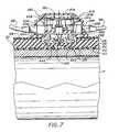
- FIG. 7is an enlarged cross-section view of a local controller module of this invention taken substantially along section line 7 — 7 of FIG. 2 ;
- FIG. 8is a schematic diagram of the socket circuit board routing of power and signals between daisy chained inputs and outputs and to and from other pipe heater and local controller module components;
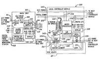
- FIG. 9is a functional block diagram of the pipe heater control system of the present invention including a monitoring station in communication with three pipeline heater systems having base units and local heater controller modules; and
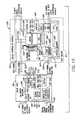
- FIG. 10is a functional electrical block diagram of one of the base units and local controller modules and interconnected pipe heaters of FIG. 9 .
- FIGS. 1 and 2A pipe heater control system 10 according to this invention is shown in FIGS. 1 and 2 with an example of three of the local controller units 100 of this invention mounted on three pipe heaters 97 in a daisy chain connection to a base unit 92 .
- the three pipe heaters 97are mounted on a pipe P to be heated in a typical manner, for example, as described in U.S. Pat. No. 5,714,738 issued to Hauschulz et al., which describes the structures, materials, and uses of such pipe heaters and is incorporated herein by reference for all that it discloses. While some of the pipe heater 97 structural details will be described below, suffice it to say at this point that each pipe heater 97 can be secured on the pipe P by one or more straps 21 .
- the pipe heaters 97 and local controller modules 100are connected together in daisy chain fashion by daisy chain cords 98 , which will be described in more detail below.
- the first pipe heater 97 and local controller module 100 in the daisy chainare connected to the base unit 92 by an extension cord 94 .
- a typical pipe heater 97comprises a heating mat or core component 22 with an inside surface 23 that is adapted to interface with the pipe P, a thermal insulation layer 25 bonded to the outside surface 24 of the heating component 22 , and a jacket or partial jacket 26 from which the straps 21 extend.
- a set of resistive heater wires or heater elements 126are embedded in the heating mat or core component 22 and are powered by high-voltage alternating current (AC) electric power, typically 120 volts or 240 volts, 50 or 60 hertz, to produce heat, although other voltages and/or hertz power and other kinds of heat producing components can be used.
- ACalternating current
- the local controller module 100 on each pipe heater 97controls the high-voltage AC electric power to the resistive heater wires 126 based on a set point temperature, as will be explained in more detail below. Suffice it to say at this point that the high-voltage AC power is delivered to the pipe heaters 97 by the extension cord 94 from the base unit 92 ( FIGS. 1 and 2 ) and by the daisy chain cords 98 (FIGS. 1 - 3 ).
- a temperature sensor 142can be embedded in the thermal insulation 25 , preferably on the surface 24 of the heating component 22 , so that it is not buffered from heat or temperature of the heating component 22 by any insulation 25 between it and the heating component 22 .
- An electric circuit, such as the local controller process circuit 101 , in the local controller module 100compares a signal from the temperature sensor 142 with a set point temperature and, if the signal from the temperature sensor 142 indicates the temperature of the heating component 22 is less than the set point temperature or less than a certain range from the set point temperature, then the electric circuit 101 will turn “on” the high-voltage AC electric power to the heater element 126 to produce more heat. On the other hand, if the signal from the temperature sensor 142 indicates that the temperature of the heating component 22 is higher than the set point temperature or higher than a certain range from the set point temperature, then the electric circuit 101 will turn “off” the high voltage electric power to the heater element 126 .
- the local controller process circuit 101may include a microprocessor 134 ( FIG. 10 ) to accomplish these and other functions, as explained below.
- the electric local controller process circuit 101 in the local controller module 100is powered by low voltage DC current, e.g., 9 volts, which is produced by a dc power supply in the base unit 92 ( FIGS. 1 and 2 ) and delivered to the local controller modules 100 by the extension cord 94 and daisy chain cords 98 .
- the dc power supplyproduces the low-voltage dc power from the high-voltage AC power obtained by the base unit 92 from public utility or other AC power source available in the vicinity and delivered to the base unit 92 by a conventional power cord 91 .
- dc power suppliesthat produce low-voltage dc current from high-voltage AC electric current consume substantial amounts of power that is manifested in creation of substantial amounts of heat, which must be dissipated to avoid high temperatures that could damage electric circuit components. Enough heat can be dissipated naturally in ambient atmospheric or room temperature environments, where the base unit 92 is usually situated, to avoid such damage to circuit components. Therefore, no bulky heat dissipation devices are needed for such de power supplies in the base unit 92 .
- the local controller modules 100are positioned on the pipe heaters 97 , which are hot themselves. Therefore, it would be much more difficult to dissipate heat from a dc power supply located in the local controller module 100 and would require at least bulky heat sink material with fins or other devices to dissipate heat produced by a dc power supply. Second, providing a dc power supply at each local controller module 100 , instead of at the base unit 92 only, would multiply power consumed by the heater control system 10 . Therefore, in the interest of optimizing size, power consumption, and other considerations, it is preferred to allocate the dc power-production function for the local controller modules 100 to the base unit 92 .
- locating the heater control functions of comparing temperature sensor 142 signals with set point temperatures and switching the high-voltage AC power “on” and “off” at the local controller modules 100is preferable over providing those functions in the base unit 92 or elsewhere.
- this allocation of functionsallows independent temperature control of each pipe heater 97 with minimal circuitry 101 without the need for dedicated AC power and data communication wires from the base unit to each individual pipe heater 97 , which would inhibit the simple daisy chain connectability of the local controller modules 100 to the base unit 92 according to this invention.
- a significant feature of this inventionis the combination modular and daisy chained connectivity of the pipe heaters 97 and local controller modules 100 to the base unit 92 via socket 200 in the pipe heaters 97 , as best seen in FIGS.1-7 .
- the socket 200has a socket frame 202 that is either molded as an integral part of the jacket 26 or bonded to the jacket 26 and a socket circuit board 204 that is mounted in the socket frame 202 .
- the socket circuit board 204enables the combination modular and daisy chained connectivity of this invention by serving a number of functions, including: (i) routing the high-voltage AC electric power from one daisy chain connector 206 to the other daisy chain connector 208 , both of which are integral parts of the socket circuit board 200 ; (ii) routing high-voltage AC power to the local controller module 100 for switching “on” and “off”; (iii) routing switched Aon@ high-voltage AC power from the local controller module 100 to the heater element 126 ; (iv) routing low-voltage dc power from one daisy chain connector 206 to the other daisy chain connector 208 ; (v) routing low-voltage dc power to the local controller process circuit 101 ( FIG.
- the bottom of the local controller module 100is shown in FIG. 4 , when viewed in combination with the top of the socket circuit board 204 , illustrates the male parts 210 ′, 212 ′ of connectors 210 , 212 , respectively, which plug into the corresponding female parts of those connectors 210 , 212 to facilitate the “plug-in” mounting or docking of the local controller module 100 on the socket 200 of pipe heater 97 . All of high-voltage AC, low-voltage dc, temperature sensor signals, and data links to and from the local controller module 100 , are established by merely docking or plugging the local controller module 100 into the socket 200 .
- the retainer bars 216 , 218interact with the plug ends 99 of daisy chain cords 98 to help retain the local controller module 100 on the socket 200 .
- the local controller module 100can be removed from the pipe heater 97 by unplugging daisy chain cords 98 from connectors 206 , 208 and unplugging the local control module 100 from plug connectors 210 , 212 by simply pulling the local controller module 100 away from the socket 200 .
- FIG. 6The mounting of the socket circuit board 204 in the socket frame 202 is illustrated in FIG. 6 , where the socket circuit board 204 is poised for insertion into the bottom of the socket frame 202 .
- Apertures 222 , 224 , 226 in the top of socket frame 202accommodate insertion of connecters 206 , 208 , 210 , 212 through the socket frame 202 .
- the socket frame 202is preferably slightly elastic, so it can be deformed enough to insert the edges of the socket circuit board 204 over the ledges 232 , 234 to retain the socket circuit board 202 in the socket frame 202 .
- the high-voltage AC wire leads 236 , 238 to the heater element 126 and the wire leads 242 , 244 from the temperature sensor 142are soldered to appropriate posts 246 , 248 and 252 , 254 , as best seen in FIG. 7.
- a plurality of other posts 240 and traces 250 illustrated diagrammatically in FIG. 6provide the routing functions of the socket circuit board 204 , as explained above.
- the control circuit 101which will be provided in more detail below, is positioned primarily on a controller circuit board 256 .
- the controller circuit board 256is mounted in the housing 214 , and the top and bottom parts of the housing 214 with the circuit board 256 are held together by a pair of screws 258 , 259 .
- the preferred embodiment heater control system 10 of this inventionhas six wire conductors in the extension cord 94 and in each daisy chain cord 98 , and all six of them trace straight through the socket circuit board 204 from connector 206 to connector 208 to accommodate the daisy chain connection of one set of pipe heater 97 and local controller module 100 to another.
- Two wires 124 , L 1 and L 2carry the high-voltage AC current for powering the heater elements 126 .
- One of the traces L 1 , L 2is tapped to the heater element 126 and the other passes via connector 212 to some type of power switch 130 in the local controller module 100 , as will be described in more detail below, before returning back through connector 212 and socket circuit board 204 to the heater element 126 .
- the low voltage (e.g., +9 volts) dc poweris carried on two wires 120 (+9 volt and common), both of which are also traced straight through the socket circuit board 204 from connector 206 to connector 208 .
- Both the +9 volt and common (COM) tracesare tapped into the local controller module 100 via connector 210 to power the local controller process circuit 101 .
- each pipe heater 97 and local controller module 100operate off all of the wires 124 , 120 , 122 (L 1 , L 2 , +9V, COM, A, and B) in electrical parallel connection to other pipe heaters and local controller modules 100 in a daisy chain according to this invention.
- the two wires 143are purely local and not included in the extension cord 94 or daisy chain cords 98 , but they trace through the socket circuit board 204 from the temperature sensor 142 to the local controller process circuit 101 via the connector 210 for the purposes described above.
- the preferred heater control system 10is illustrated diagrammatically in FIG. 9 and generally includes an optional central monitoring station 72 with a user interface 74 (i.e., a monitor, with or without a touch screen capability, a keyboard(s), a mouse, and other peripheral computer interface equipment), a central processing unit (CPU) 76 in communication with the user interface 74 and memory 78 which may contain software for use in monitoring and controlling heaters and heater controllers, databases with temperature “recipes” for various processes and other temperature and maintenance information, and a communication port 80 for receiving and transmitting digital data.
- a user interface 74i.e., a monitor, with or without a touch screen capability, a keyboard(s), a mouse, and other peripheral computer interface equipment
- CPUcentral processing unit
- memory 78which may contain software for use in monitoring and controlling heaters and heater controllers, databases with temperature “recipes” for various processes and other temperature and maintenance information
- a communication port 80for receiving and transmitting digital data.
- the central monitoring station 72is connected with communication lines 81 , 82 , and 83 to, for example, three pipe heater control systems 84 , 86 , and 88 , on pipes 85 , 87 , and 89 , respectively.
- the central monitoring station 72allows a user at a remote location to quickly monitor the temperature of each heater in the heater control systems 84 , 86 , and 88 and in some embodiments, to transmit commands via the communication lines 81 , 82 , and 83 to change the temperature settings of the individual heaters or otherwise control operation (e.g., turn the heaters on and off).
- a single central monitoring station 72can be used to control and monitor a very large number of heaters and heater systems (although only three are shown for ease of illustration).
- its integration with a single pipe heater control system 86will be discussed in detail in connection with the description of the components of the control system 86 .
- the control system 86may be utilized separate from the heater control system 10 .
- the pipe heater control system 86provide control and supply power to a number of controllers and heaters with the use of a minimum number of leads, wires, and/or lines to avoid the rat's nest problem that is prevalent with prior art control systems.
- the pipe heater control system 86includes the base unit 92 that communicates with the central monitoring station 72 via communication line 82 and receives AC power from a single AC power supply 90 over line 91 .
- the base unit 92includes a digital input and output device 116 for communication with the central monitoring station 72 and a digital I/O 112 for transmitting commands and information requests from the central monitoring station 72 and the base station 92 to satellite (local) controllers 96 , 100 , 104 and for receiving digital signals from the same local controllers 96 , 100 , 104 .
- both of these communication interfacesare configured to use both the EIA RS-232 and RS-485 standards at a fixed baud rate of 9600 baud.
- the base unit 92includes an optional ground fault interrupt 106 and a 12-amp circuit breaker 108 for increasing the operating safety of the control system 86 and for isolating the local controller modules 100 from the AC power supply 90 in the event of a short circuit or ground fault condition. Additionally, the base station 92 includes a DC power supply 110 (e.g., a 9-volt DC power supply) for supplying DC power for electronic temperature control components of each local controller module 100 .
- a DC power supply 110e.g., a 9-volt DC power supply
- the AC power output, DC power output, and digital I/O linesare integrated and/or contained within a single communication/power extension cord 94 that is passed to the first local control module 100 .
- the communication/power extension cord 94 and daisy chain cords 98are illustrated as coiled in FIG. 9 , because such coiling further enhances ease of installation and maintenance at the specific location of each local controller module 100 , and the distance between the same may vary with each application.
- control system 86With the combination of a coiled cord 94 (as well as daisy chain cords 98 ) and integration of power and communication lines into a single cord 94 (and daisy chain cords 98 ), the control system 86 is able to readily achieve the goals of minimizing the complexity of the system, reducing space requirements, and increasing the ease of installation and replacement (i.e., each line 94 , 98 and local controller modules 100 can be individually plugged into the system 86 ).
- each local controller module 100To allow a single line to be fed from the base unit 92 , it is important that power and communication lines be passed through each local controller module 100 to allow the local controller modules 100 to be daisy chained together. This integration of power and temperature sensing and control at each local controller module 100 is achieved as illustrated in the functional block diagram of FIG. 10 .
- each of the local controller modules 100to be housed in a single housing 148 as illustrated in FIGS. 1-7 .
- the size of the housing 148is maintained relatively small (i.e., a width, W, of less than about 64 mm, a height, H, of less that about 32 mm, and a length, L, of less than about 70 mm).
- the local controller module 100 and housing 148are configured, in this exemplary embodiment, for mating with a docking port or socket 200 attached to a wrap around flexible pipe heater 97 as described above.
- the local controller module 100is configured to receive AC power from the base unit 92 via cord 94 on leads 124 which are directed into the heater 97 .
- FIG. 10is schematic, so the exact locations of lines e.g., line 120 , 122 , 124 etc. are not shown in FIG. 10 . See FIG. 8 and related description for the preferred location of those lines or wires 120 , 122 , 124 in the socket circuit board 204 , as explained above.
- the heater 97includes heater element 126 that operates on the AC power on leads 124 and is electronically controlled (i.e., turned on and off) via leads 128 and 131 by opto-coupler zero voltage power switch 130 (although other electronic switching devices may readily be utilized).
- the local controller module 100brings DC power in with leads 120 which power the microprocessor 134 and other electronic components via leads 132 .
- the microprocessor 134is included in the local controller module 100 to provide better control over the temperature settings of the heater 97 , to operate operational displays 146 at the controller 100 , to operate the power switch 130 to maintain temperatures within a desired and user adjustable range, and to provide digital communication capability with the base station 92 and in some cases, the monitoring station 72 .
- the temperature sensor 142e.g., a thermistor, thermocouple, or the like
- the temperature sensor 142which is positioned adjacent the heater surface 24 responds to temperature changes in the heater surface 24 and outputs on lead 143 a representative signal (such as a voltage signal).
- Sense amplifier 144amplifies this signal and transmits an analog signal to the microprocessor 134 which includes an analog to digital converter 136 .
- the microprocessor 134is configured to process the digital signal from sense amplifier 144 to determine the temperature of the heater surface 24 . The microprocessor 134 then determines if the heater surface 24 temperature is within an acceptable range about a temperature set point.
- the controller 100is preferably adapted to allow a user to control (i.e., set and later adjust) the temperature at which the heater 97 is operated. Typically, this is achieved by setting a temperature set point and, in some embodiments, a range of variation about this set point (or the temperature band about the temperature set point may be fixed by the electronic temperature control technique utilized, e.g., if on-off control is used with turning on a heater at a low temperature setting and turning the heater off at a high temperature setting). As illustrated in FIG.
- the controller 100includes an 8-position dip switch 140 which allows the user to either manually set the temperature set point (e.g., by setting the binary number of a desired temperature in the 8 position dip switch 140 ) or remotely by setting all the switches of the dip switch 140 to zero or other designated remote mode settings and then remotely communicating a temperature set point to the microprocessor 134 via digital communication lines 122 from the monitoring station 72 (which is stored in memory of the microprocessor 134 ).
- the dip switch 140is accessed by unplugging the local controller module 100 from the docking port or socket 200 of the heater 97 .
- the microprocessor 134compares the temperature determined from signals from the temperature sensor 142 with the temperature setting of the 8 position dip switch 140 via lines 141 or the temperature received from the monitoring station 72 to verify whether the heater surface 24 is within an acceptable temperature range (such as, for example, within 5° C. and more preferably within about 2° C. of the temperature set point). If the heater surface 24 temperature is under the acceptable temperature range, the microprocessor 134 functions to operate the switch 130 to operate the heater 97 and to communicate this temperature status to the base station 92 over leads 138 and 122 .
- an acceptable temperature rangesuch as, for example, within 5° C. and more preferably within about 2° C. of the temperature set point.
- the base unit 92may have its own operation status display 114 and/or an alarm status relay 118 for activating audio and visual alarms either at the base station 92 or at a remote location (e.g., a flashing light that is readily visible from a distance).
- the operation status display 114“lights” a blue LED when at least one of the pipe heaters 97 is under its set temperature range, lights a green LED when all of the pipe heaters 97 are within their set temperature ranges, and lights a red LED when one of the pipe heaters 97 is above its set temperature range.
- the base unit 92concurrently transmits the temperature and operating information for each pipe heater 97 to the monitoring station 72 where it can be displayed on the user interface 74 and/or stored in memory 78 .
- the microprocessor 134also functions to operate a local display 146 with three colored LEDs similar to that discussed for the base unit 92 that enables a user to quickly, visually monitor each of the pipe heaters 97 in a pipe line.
- the LED display 146is readily visible on the upper, exterior portion of the controller housing 148 (see FIG. 3 ).
- the microprocessor 134continues to monitor and compare the heater surface 24 temperature, and, once the temperature reaches a predetermined point within the temperature range, the microprocessor 134 functions to operate the switch 130 to turn off the heater 97 , communicate “within range” information to the base unit 92 (and thereby, the monitoring station), and operate the display 146 of the local controller module 100 .
- the microprocessor 134then continues to monitor the temperature of the heater surface 24 to communicate if the temperature is over or out of an acceptable range and to repeat the above operations when the temperature falls under the preset temperature range.
- the control logic exercised by the microprocessor 134can be a simple on/off control, a version of PID control, and other control functions.
- each pipe heater 97can be set and maintained within a relatively tight temperature range (such as a 1 to 2° C. range).
- a relatively tight temperature rangesuch as a 1 to 2° C. range.
- the use of a monitoring station 72 and remotely programmable local controller modules 100allows a user to establish and rapidly change the temperatures of each of the pipe heaters 97 to establish relatively complex recipes for changing processes.
- the configuration of the heater control system 10allows a user to remotely and locally monitor the operation of each local controller module 100 and pipe heater 97 to enhance process monitoring and to decrease the time spent on troubleshooting.
- each of the local controller modules 100is designed to allow a user to unplug a single controller 100 and/or its associated power/communication cords 94 , 98 and plug in replacements.
- the base unit 92operates to at least periodically, such as once every 2 seconds or some other fixed time period, poll the connected local controller modules 100 for status (e.g., temperature) and diagnostic information.
- a counter mechanism or routinemay be included within the microprocessor 134 to track the times they are operated.
- electro-mechanical relaystypically have a fixed operating life and it may be useful to include a counter for each included electro-mechanical relay to count the times they are activated.
- the microprocessor 134sends this information to the base unit 92 to establish a maintenance flag for the local controller module 100 .
- FIG. 9a separate AC power supply and base station was shown for each pipe line and this configuration was selected to easily comply with certain electrical safety standards.
- the illustrated heater control system 10can be modified to include a single AC power source and a single base station that together provide AC power to multiple control systems 84 , 86 , and 88 .
Landscapes
- Engineering & Computer Science (AREA)
- Remote Sensing (AREA)
- Physics & Mathematics (AREA)
- General Physics & Mathematics (AREA)
- Automation & Control Theory (AREA)
- Control Of Resistance Heating (AREA)
Abstract
Description
Claims (23)
Priority Applications (2)
| Application Number | Priority Date | Filing Date | Title |
|---|---|---|---|
| US09/907,494US6894254B2 (en) | 2000-04-20 | 2001-07-16 | Heater control system with combination modular and daisy chained connectivity and optimum allocation of functions between base unit and local controller modules |
| TW91114606ATW554161B (en) | 2001-07-16 | 2002-07-02 | Heater control system with combination modular and daisy chained connectivity and optimum allocation of functions between base unit and local controller modules |
Applications Claiming Priority (2)
| Application Number | Priority Date | Filing Date | Title |
|---|---|---|---|
| US55341600A | 2000-04-20 | 2000-04-20 | |
| US09/907,494US6894254B2 (en) | 2000-04-20 | 2001-07-16 | Heater control system with combination modular and daisy chained connectivity and optimum allocation of functions between base unit and local controller modules |
Related Parent Applications (1)
| Application Number | Title | Priority Date | Filing Date |
|---|---|---|---|
| US55341600AContinuation-In-Part | 2000-04-20 | 2000-04-20 |
Publications (2)
| Publication Number | Publication Date |
|---|---|
| US20020008101A1 US20020008101A1 (en) | 2002-01-24 |
| US6894254B2true US6894254B2 (en) | 2005-05-17 |
Family
ID=46204198
Family Applications (1)
| Application Number | Title | Priority Date | Filing Date |
|---|---|---|---|
| US09/907,494Expired - LifetimeUS6894254B2 (en) | 2000-04-20 | 2001-07-16 | Heater control system with combination modular and daisy chained connectivity and optimum allocation of functions between base unit and local controller modules |
Country Status (1)
| Country | Link |
|---|---|
| US (1) | US6894254B2 (en) |
Cited By (28)
| Publication number | Priority date | Publication date | Assignee | Title |
|---|---|---|---|---|
| US20040015268A1 (en)* | 2000-09-29 | 2004-01-22 | Hiroyuki Kato | Display and control unit, variety management apparatus, relay communication apparatus, communication device, and broadcast system |
| US20060230298A1 (en)* | 2005-04-11 | 2006-10-12 | Watlow Electric Manufacturing Company | Compact limiter and controller assembly and method |
| US20060230297A1 (en)* | 2005-04-11 | 2006-10-12 | Watlow Electric Manufacturing Company | Electronic device mounting assembly and method |
| US20060229740A1 (en)* | 2005-04-11 | 2006-10-12 | Watlow Electric Manufacturing Company | Portable user interface assembly and method |
| US20060230296A1 (en)* | 2005-04-11 | 2006-10-12 | Watlow Electric Manufacturing Company | Controller housing with connector retention assembly and method |
| US20060249507A1 (en)* | 2005-04-11 | 2006-11-09 | Watlow Electric Manufacturing Company | Modular controller user interface and method |
| US20070058315A1 (en)* | 2005-09-09 | 2007-03-15 | Maddox Harold D | Controlling spas |
| US20070204177A1 (en)* | 2006-02-02 | 2007-08-30 | Watlow Electric Manufacturing Company | Power controller coupling assemblies and methods |
| US20070235440A1 (en)* | 2006-04-05 | 2007-10-11 | Youfan Gu | Multiple heater control system with expandable modular functionality |
| US20070284363A1 (en)* | 2006-06-12 | 2007-12-13 | Kim Yoon-Hae | Temperature control apparatus of heating jacket |
| US20090012655A1 (en)* | 2007-07-05 | 2009-01-08 | Baxter International Inc. | Dialysis fluid heating algorithms |
| US20090065597A1 (en)* | 2005-12-12 | 2009-03-12 | Garozzo James P | Low voltage power line communication for climate control system |
| US20100032422A1 (en)* | 2008-08-08 | 2010-02-11 | Hong Fu Jin Precision Industry (Shenzhen)Co., Ltd. | Data input device |
| US20100155388A1 (en)* | 2008-12-22 | 2010-06-24 | Cherif Menassa | Pulse modulation heating system and method |
| US20100262403A1 (en)* | 2009-04-10 | 2010-10-14 | Bradford White Corporation | Systems and methods for monitoring water heaters or boilers |
| US20110202034A1 (en)* | 2010-02-17 | 2011-08-18 | Estill Medical Technologies, Inc. | Modular medical fluid heating apparatus |
| US20110213510A1 (en)* | 2010-03-01 | 2011-09-01 | Koorosh Mozayeny | Smart power strip |
| US20110308814A1 (en)* | 2006-04-21 | 2011-12-22 | James Louis Menotti | Joint used for coupling long heaters |
| CN104880965A (en)* | 2014-02-28 | 2015-09-02 | 西门子公司 | Power module and interface module for a heating management and/or control system and modular system for heating management and/or control system |
| WO2015167658A1 (en) | 2014-04-28 | 2015-11-05 | Mks Instruments, Inc. | Streamlined heater assembly with front and intermediate daisy chain power injection, shielding, and water resistant features |
| TWI554748B (en)* | 2014-06-13 | 2016-10-21 | 台灣高速鐵路股份有限公司 | A portable digitalb temperature and humidity sensing device with automatically switches master/slave mode |
| US20170107620A1 (en)* | 2015-10-16 | 2017-04-20 | Hitachi Kokusai Electric Inc. | Heating part, substrate processing apparatus, and method of manufacturing semiconductor device |
| US10021739B2 (en) | 2015-07-08 | 2018-07-10 | Mks Instruments, Inc. | Trimmable heater |
| US10225953B2 (en) | 2014-10-31 | 2019-03-05 | Thermal Corp. | Vehicle thermal management system |
| US10237918B2 (en) | 2015-07-15 | 2019-03-19 | Adrian M. ADAMSON | Apparatus for temperature measurement and control using two wires per thermal zone and methods of use |
| WO2023010456A1 (en)* | 2021-08-05 | 2023-02-09 | Abb Schweiz Ag | Temperature sensing device and switchgear |
| US11654221B2 (en) | 2003-11-05 | 2023-05-23 | Baxter International Inc. | Dialysis system having inductive heating |
| US20230332956A1 (en)* | 2022-04-18 | 2023-10-19 | Directlytek Technology Co., Ltd. | Disaster prevention and warning system |
Families Citing this family (34)
| Publication number | Priority date | Publication date | Assignee | Title |
|---|---|---|---|---|
| US8809748B2 (en)* | 2004-05-17 | 2014-08-19 | Colin Regan | Apparatus and method for post heat treating pipe or weld joints |
| US20060021571A1 (en)* | 2004-07-28 | 2006-02-02 | Taiwan Semiconductor Manufacturing Co., Ltd. | Vacuum pump line with nickel-chromium heater layer |
| US7613855B2 (en)* | 2004-08-26 | 2009-11-03 | A. O. Smith Corporation | Modular control system and method for water heaters |
| US8660701B2 (en) | 2004-08-26 | 2014-02-25 | A. O. Smith Corporation | Modular control system and method for water heaters |
| US7574120B2 (en) | 2005-05-11 | 2009-08-11 | A. O. Smith Corporation | System and method for estimating and indicating temperature characteristics of temperature controlled liquids |
| DE102006047431A1 (en)* | 2005-10-06 | 2007-05-10 | Purifics Environmental Technologies, Inc., London | Industrial network has hybrid cable that connects controllers together in accordance with daisy-chain principle and transfers control and/or data signals as well as operating current for intelligent controllers over daisy-chain |
| US7412347B2 (en)* | 2006-01-23 | 2008-08-12 | Sherwood Engineering Design Services, Inc. | Method and apparatus for measuring physical parameters |
| US8887671B2 (en)* | 2006-03-27 | 2014-11-18 | A. O. Smith Corporation | Water heating systems and methods |
| US20070246557A1 (en)* | 2006-03-27 | 2007-10-25 | Phillips Terry G | Water heating systems and methods |
| US20070245980A1 (en)* | 2006-03-27 | 2007-10-25 | Phillips Terry G | Water heating systems and methods |
| US8245669B2 (en)* | 2006-03-27 | 2012-08-21 | A. O. Smith Corporation | Water heating systems and methods |
| CA2641492C (en)* | 2007-10-23 | 2016-07-05 | Fiberspar Corporation | Heated pipe and methods of transporting viscous fluid |
| US20090139972A1 (en)* | 2007-10-23 | 2009-06-04 | Psion Teklogix Inc. | Docking connector |
| US20090302019A1 (en)* | 2008-06-05 | 2009-12-10 | Tim Selenski | Apparatus and Method for Vaporizing Volatile Material |
| DE102010061271A1 (en)* | 2010-12-15 | 2012-06-21 | Contitech Schlauch Gmbh | Heatable connection device for media-carrying, electrically heatable hoses |
| JP6034126B2 (en)* | 2012-10-16 | 2016-11-30 | 株式会社東京技術研究所 | Multiple heater inspection system |
| WO2014089305A1 (en)* | 2012-12-05 | 2014-06-12 | Husky Injection Molding Systems Ltd. | Injection molding apparatus |
| DE102012112370A1 (en)* | 2012-12-17 | 2014-06-18 | Krones Ag | Device for heating plastic preforms |
| KR101341108B1 (en)* | 2013-05-10 | 2013-12-13 | 김학출 | Apparatus for controlling heater of semiconductor manufacturing equipments |
| DE102013104931A1 (en)* | 2013-05-14 | 2014-11-20 | MAQUET GmbH | Arrangement for heating a patient support surface |
| US9715813B1 (en)* | 2014-03-02 | 2017-07-25 | Durex International Corp | Visibility electronic controller and current-based status monitor |
| CN104390492B (en)* | 2014-11-25 | 2016-06-15 | 郑州四维淀粉技术开发有限公司 | A kind of horizontal pair of phase-change heat-exchanger |
| KR101602127B1 (en)* | 2014-12-17 | 2016-03-11 | 주식회사 티에스시 | Heater for Pipe |
| JP6504898B2 (en)* | 2015-04-20 | 2019-04-24 | 株式会社マキタ | Shoulder type fluid device |
| US20230157924A1 (en)* | 2015-04-30 | 2023-05-25 | Lillie A Mosaddegh | Meibomian Gland Roller System with Eye Pads |
| US10579080B2 (en)* | 2018-04-06 | 2020-03-03 | Simmonds Precision Products, Inc. | Intelligent ice protection network |
| US10996276B2 (en) | 2019-01-25 | 2021-05-04 | Dell Products, L.P. | Host illumination of indicators of an AC adapter |
| GB2583942A (en)* | 2019-05-14 | 2020-11-18 | Edwards Ltd | Heater control unit |
| US11760509B1 (en)* | 2019-08-26 | 2023-09-19 | Government Of The United States As Represented By The Secretary Of The Air Force | System and method improving satellite capability through power sharing |
| US11473710B2 (en)* | 2019-10-15 | 2022-10-18 | Chad Michael Arntz | Heated drain or vent pipe |
| JP7643926B2 (en)* | 2021-05-10 | 2025-03-11 | 高砂熱学工業株式会社 | Piping unit, piping unit installation method, electric heater wire, and piping unit manufacturing method |
| CN113900460A (en)* | 2021-10-25 | 2022-01-07 | 哈尔滨工大卫星技术有限公司 | Temperature control method, system and medium for satellite platform |
| CN118224536A (en)* | 2024-05-24 | 2024-06-21 | 新疆石油管理局有限公司 | Variable-power heating pipeline system |
| CN118224537A (en)* | 2024-05-24 | 2024-06-21 | 新疆石油管理局有限公司 | Intelligent buried heating pipeline system |
Citations (56)
| Publication number | Priority date | Publication date | Assignee | Title |
|---|---|---|---|---|
| US3675046A (en) | 1970-09-28 | 1972-07-04 | Waynco | Control circuit |
| US3679871A (en) | 1971-01-05 | 1972-07-25 | Egils Evalds | Temperature control circuit employing a variable resistance heating element |
| US3689886A (en) | 1971-02-09 | 1972-09-05 | Thomas Industries Inc | Control system having transmitter-receiver sets for operating functional device over power lines |
| US3752956A (en) | 1972-05-03 | 1973-08-14 | Du Pont | Electrical resistance heating control circuit |
| US3789190A (en) | 1972-10-17 | 1974-01-29 | A J Matlen | Temperature regulation for electrical heater |
| US3796977A (en) | 1971-07-26 | 1974-03-12 | M Elliott | Temperature controlled transmission line |
| US3869597A (en) | 1974-02-27 | 1975-03-04 | Nasa | Self-regulating proportionally controlled heating apparatus and technique |
| US4086466A (en) | 1976-04-30 | 1978-04-25 | Scharlack Ronald S | Automatic heater controller |
| US4237369A (en)* | 1979-01-31 | 1980-12-02 | Jones Robert H | Wild stress relief power supply apparatus |
| US4268818A (en) | 1978-03-20 | 1981-05-19 | Murray W. Davis | Real-time parameter sensor-transmitter |
| US4290056A (en) | 1979-07-05 | 1981-09-15 | Ellsworth, Chow & Murphy, Inc. | Protective system |
| US4329569A (en) | 1979-05-16 | 1982-05-11 | Bulten-Kanthal Ab | Resilient snap-on electric heating jacket for tubular objects |
| US4400688A (en) | 1976-01-16 | 1983-08-23 | New England Power Service Company | Method and apparatus for communication over electric power lines |
| US4418333A (en) | 1981-06-08 | 1983-11-29 | Pittway Corporation | Appliance control system |
| US4446462A (en) | 1982-03-01 | 1984-05-01 | General Electric Company | Method and apparatus for multiple frequency transmission of information in a digital communication system |
| US4474825A (en) | 1982-03-08 | 1984-10-02 | Northern Telecom Limited | Monitoring temperature of wire during heating |
| US4506146A (en) | 1981-08-21 | 1985-03-19 | Reynolds Metals Company | Wire temperature controller |
| US4507546A (en) | 1983-03-01 | 1985-03-26 | Fortune William S | Control circuit responsive to a component's varying resistance |
| US4540875A (en)* | 1982-05-04 | 1985-09-10 | Silver Lake Corporation | Electric storage heater system having charging control that transmits charging information over power lines |
| US4549073A (en) | 1981-11-06 | 1985-10-22 | Oximetrix, Inc. | Current controller for resistive heating element |
| US4635040A (en) | 1985-03-12 | 1987-01-06 | Masot Oscar V | Fire detection alarm system |
| US4636619A (en) | 1982-05-31 | 1987-01-13 | Hideo Sugimori | Heater control device |
| US4638850A (en)* | 1984-02-28 | 1987-01-27 | A. T. Newell Co. Inc. | Electronic thermostat |
| US4673127A (en) | 1986-07-17 | 1987-06-16 | Grant Willie T | Remote control means for heating/cooling devices |
| US4694145A (en) | 1985-02-15 | 1987-09-15 | Allied Corporation | Electronic controller for predetermined temperature coefficient heater |
| US4697166A (en) | 1986-08-11 | 1987-09-29 | Nippon Colin Co., Ltd. | Method and apparatus for coupling transceiver to power line carrier system |
| US4737769A (en) | 1985-03-12 | 1988-04-12 | Masot Oscar V | Fire detection alarm system |
| US4778980A (en) | 1986-10-06 | 1988-10-18 | Xerox Corporation | Instant-on fuser control |
| US4864274A (en) | 1988-10-24 | 1989-09-05 | Northern Microdesign Inc. | Remote reading thermostat |
| US4874925A (en) | 1987-06-01 | 1989-10-17 | Dickenson Wilk A | Electrically heated hose assembly for conveying electrically conductive liquids |
| US4950872A (en) | 1989-08-16 | 1990-08-21 | Therme, Inc. | Control circuit for a source of heat |
| US4994792A (en) | 1989-12-06 | 1991-02-19 | Ziegler Jr Eldon W | Fluid temperature monitoring system |
| US5015826A (en)* | 1988-05-27 | 1991-05-14 | Curti S.N.C. Di Curti Pietro & C. | Power adjustment device for electric power systems, in particular for electric power systems with electric ovens |
| US5021634A (en) | 1986-11-05 | 1991-06-04 | Giovanni Santoro | Temperature controlled soldering iron employing a variable resistance heating element for temperature sensing |
| US5022459A (en) | 1988-12-06 | 1991-06-11 | Chiles Daniel T | Flexible hose heat exchanger construction with combination locating and thawing wire |
| US5031082A (en) | 1989-11-27 | 1991-07-09 | Bierend Gary D | Remotely controlled security lighting |
| US5120936A (en) | 1990-08-22 | 1992-06-09 | Industrial Technology Research Institute | Multiplex heating system with temperature control |
| US5128653A (en) | 1988-10-31 | 1992-07-07 | Hochiki Corporation | Fire alarm system |
| US5196830A (en) | 1988-02-24 | 1993-03-23 | Birging Torbjoern | Apparatus for supervising objects with regard to overheating |
| US5225811A (en) | 1992-02-04 | 1993-07-06 | Analog Devices, Inc. | Temperature limit circuit with dual hysteresis |
| US5463375A (en) | 1990-06-19 | 1995-10-31 | Dylec Ltd. | Status-reporting device for reporting a predetermined temperature state, temperature sensor suitable for such a status-reporting device, and process for the production of such a temperature sensor |
| US5464965A (en) | 1993-04-20 | 1995-11-07 | Honeywell Inc. | Apparatus for controlling temperature of an element having a temperature variable resistance |
| US5550350A (en) | 1994-11-17 | 1996-08-27 | Donald W. Barnes | Heated ice-melting blocks for steps |
| US5566879A (en) | 1993-12-06 | 1996-10-22 | Comptel Domotique Inc. | System for centralized controlling of a plurality of temperature regulating devices |
| US5600306A (en) | 1994-10-17 | 1997-02-04 | Nisso Industry Co., Ltd. | Receptacle unit and extension cord |
| US5632919A (en) | 1996-01-25 | 1997-05-27 | T.G.M., Inc. | Temperature controlled insulation system |
| US5658480A (en) | 1995-09-05 | 1997-08-19 | Therm-O-Disc, Incorporated | Heating element control |
| US5667712A (en) | 1996-02-16 | 1997-09-16 | Watlow Electric Manufacturing Company | Expandable multi-segment band heater construction with improved electrical connection |
| US5689230A (en) | 1995-11-09 | 1997-11-18 | Motoral, Inc. | Energy monitoring and control system using reverse transmission on AC line |
| US5694108A (en) | 1996-05-01 | 1997-12-02 | Abb Power T&D Company Inc. | Apparatus and methods for power network coupling |
| US5708256A (en) | 1995-12-18 | 1998-01-13 | Kaz, Incorporated | Heating pad controller with variable duty cycle for temperature adjustment |
| US5789722A (en) | 1996-11-12 | 1998-08-04 | Zimac Laboratories, Inc. | Modular multizone heater system and method |
| US5791377A (en) | 1996-07-08 | 1998-08-11 | Yazaki Corporation | Electrically heated conduit |
| US5900179A (en) | 1996-01-16 | 1999-05-04 | Intech 21, Inc. | Heating cable control and monitoring method and system |
| US6023052A (en)* | 1997-11-07 | 2000-02-08 | Shell Oil Company | Heater control |
| US6142974A (en) | 1998-09-18 | 2000-11-07 | Estill Medical Technologies, Incorporated | Portable I.V. fluid warming system |
- 2001
- 2001-07-16USUS09/907,494patent/US6894254B2/ennot_activeExpired - Lifetime
Patent Citations (56)
| Publication number | Priority date | Publication date | Assignee | Title |
|---|---|---|---|---|
| US3675046A (en) | 1970-09-28 | 1972-07-04 | Waynco | Control circuit |
| US3679871A (en) | 1971-01-05 | 1972-07-25 | Egils Evalds | Temperature control circuit employing a variable resistance heating element |
| US3689886A (en) | 1971-02-09 | 1972-09-05 | Thomas Industries Inc | Control system having transmitter-receiver sets for operating functional device over power lines |
| US3796977A (en) | 1971-07-26 | 1974-03-12 | M Elliott | Temperature controlled transmission line |
| US3752956A (en) | 1972-05-03 | 1973-08-14 | Du Pont | Electrical resistance heating control circuit |
| US3789190A (en) | 1972-10-17 | 1974-01-29 | A J Matlen | Temperature regulation for electrical heater |
| US3869597A (en) | 1974-02-27 | 1975-03-04 | Nasa | Self-regulating proportionally controlled heating apparatus and technique |
| US4400688A (en) | 1976-01-16 | 1983-08-23 | New England Power Service Company | Method and apparatus for communication over electric power lines |
| US4086466A (en) | 1976-04-30 | 1978-04-25 | Scharlack Ronald S | Automatic heater controller |
| US4268818A (en) | 1978-03-20 | 1981-05-19 | Murray W. Davis | Real-time parameter sensor-transmitter |
| US4237369A (en)* | 1979-01-31 | 1980-12-02 | Jones Robert H | Wild stress relief power supply apparatus |
| US4329569A (en) | 1979-05-16 | 1982-05-11 | Bulten-Kanthal Ab | Resilient snap-on electric heating jacket for tubular objects |
| US4290056A (en) | 1979-07-05 | 1981-09-15 | Ellsworth, Chow & Murphy, Inc. | Protective system |
| US4418333A (en) | 1981-06-08 | 1983-11-29 | Pittway Corporation | Appliance control system |
| US4506146A (en) | 1981-08-21 | 1985-03-19 | Reynolds Metals Company | Wire temperature controller |
| US4549073A (en) | 1981-11-06 | 1985-10-22 | Oximetrix, Inc. | Current controller for resistive heating element |
| US4446462A (en) | 1982-03-01 | 1984-05-01 | General Electric Company | Method and apparatus for multiple frequency transmission of information in a digital communication system |
| US4474825A (en) | 1982-03-08 | 1984-10-02 | Northern Telecom Limited | Monitoring temperature of wire during heating |
| US4540875A (en)* | 1982-05-04 | 1985-09-10 | Silver Lake Corporation | Electric storage heater system having charging control that transmits charging information over power lines |
| US4636619A (en) | 1982-05-31 | 1987-01-13 | Hideo Sugimori | Heater control device |
| US4507546A (en) | 1983-03-01 | 1985-03-26 | Fortune William S | Control circuit responsive to a component's varying resistance |
| US4638850A (en)* | 1984-02-28 | 1987-01-27 | A. T. Newell Co. Inc. | Electronic thermostat |
| US4694145A (en) | 1985-02-15 | 1987-09-15 | Allied Corporation | Electronic controller for predetermined temperature coefficient heater |
| US4635040A (en) | 1985-03-12 | 1987-01-06 | Masot Oscar V | Fire detection alarm system |
| US4737769A (en) | 1985-03-12 | 1988-04-12 | Masot Oscar V | Fire detection alarm system |
| US4673127A (en) | 1986-07-17 | 1987-06-16 | Grant Willie T | Remote control means for heating/cooling devices |
| US4697166A (en) | 1986-08-11 | 1987-09-29 | Nippon Colin Co., Ltd. | Method and apparatus for coupling transceiver to power line carrier system |
| US4778980A (en) | 1986-10-06 | 1988-10-18 | Xerox Corporation | Instant-on fuser control |
| US5021634A (en) | 1986-11-05 | 1991-06-04 | Giovanni Santoro | Temperature controlled soldering iron employing a variable resistance heating element for temperature sensing |
| US4874925A (en) | 1987-06-01 | 1989-10-17 | Dickenson Wilk A | Electrically heated hose assembly for conveying electrically conductive liquids |
| US5196830A (en) | 1988-02-24 | 1993-03-23 | Birging Torbjoern | Apparatus for supervising objects with regard to overheating |
| US5015826A (en)* | 1988-05-27 | 1991-05-14 | Curti S.N.C. Di Curti Pietro & C. | Power adjustment device for electric power systems, in particular for electric power systems with electric ovens |
| US4864274A (en) | 1988-10-24 | 1989-09-05 | Northern Microdesign Inc. | Remote reading thermostat |
| US5128653A (en) | 1988-10-31 | 1992-07-07 | Hochiki Corporation | Fire alarm system |
| US5022459A (en) | 1988-12-06 | 1991-06-11 | Chiles Daniel T | Flexible hose heat exchanger construction with combination locating and thawing wire |
| US4950872A (en) | 1989-08-16 | 1990-08-21 | Therme, Inc. | Control circuit for a source of heat |
| US5031082A (en) | 1989-11-27 | 1991-07-09 | Bierend Gary D | Remotely controlled security lighting |
| US4994792A (en) | 1989-12-06 | 1991-02-19 | Ziegler Jr Eldon W | Fluid temperature monitoring system |
| US5463375A (en) | 1990-06-19 | 1995-10-31 | Dylec Ltd. | Status-reporting device for reporting a predetermined temperature state, temperature sensor suitable for such a status-reporting device, and process for the production of such a temperature sensor |
| US5120936A (en) | 1990-08-22 | 1992-06-09 | Industrial Technology Research Institute | Multiplex heating system with temperature control |
| US5225811A (en) | 1992-02-04 | 1993-07-06 | Analog Devices, Inc. | Temperature limit circuit with dual hysteresis |
| US5464965A (en) | 1993-04-20 | 1995-11-07 | Honeywell Inc. | Apparatus for controlling temperature of an element having a temperature variable resistance |
| US5566879A (en) | 1993-12-06 | 1996-10-22 | Comptel Domotique Inc. | System for centralized controlling of a plurality of temperature regulating devices |
| US5600306A (en) | 1994-10-17 | 1997-02-04 | Nisso Industry Co., Ltd. | Receptacle unit and extension cord |
| US5550350A (en) | 1994-11-17 | 1996-08-27 | Donald W. Barnes | Heated ice-melting blocks for steps |
| US5658480A (en) | 1995-09-05 | 1997-08-19 | Therm-O-Disc, Incorporated | Heating element control |
| US5689230A (en) | 1995-11-09 | 1997-11-18 | Motoral, Inc. | Energy monitoring and control system using reverse transmission on AC line |
| US5708256A (en) | 1995-12-18 | 1998-01-13 | Kaz, Incorporated | Heating pad controller with variable duty cycle for temperature adjustment |
| US5900179A (en) | 1996-01-16 | 1999-05-04 | Intech 21, Inc. | Heating cable control and monitoring method and system |
| US5632919A (en) | 1996-01-25 | 1997-05-27 | T.G.M., Inc. | Temperature controlled insulation system |
| US5667712A (en) | 1996-02-16 | 1997-09-16 | Watlow Electric Manufacturing Company | Expandable multi-segment band heater construction with improved electrical connection |
| US5694108A (en) | 1996-05-01 | 1997-12-02 | Abb Power T&D Company Inc. | Apparatus and methods for power network coupling |
| US5791377A (en) | 1996-07-08 | 1998-08-11 | Yazaki Corporation | Electrically heated conduit |
| US5789722A (en) | 1996-11-12 | 1998-08-04 | Zimac Laboratories, Inc. | Modular multizone heater system and method |
| US6023052A (en)* | 1997-11-07 | 2000-02-08 | Shell Oil Company | Heater control |
| US6142974A (en) | 1998-09-18 | 2000-11-07 | Estill Medical Technologies, Incorporated | Portable I.V. fluid warming system |
Cited By (51)
| Publication number | Priority date | Publication date | Assignee | Title |
|---|---|---|---|---|
| US20040015268A1 (en)* | 2000-09-29 | 2004-01-22 | Hiroyuki Kato | Display and control unit, variety management apparatus, relay communication apparatus, communication device, and broadcast system |
| US11654221B2 (en) | 2003-11-05 | 2023-05-23 | Baxter International Inc. | Dialysis system having inductive heating |
| US8044329B2 (en) | 2005-04-11 | 2011-10-25 | Watlow Electric Manufacturing Company | Compact limiter and controller assembly and method |
| US20060230298A1 (en)* | 2005-04-11 | 2006-10-12 | Watlow Electric Manufacturing Company | Compact limiter and controller assembly and method |
| US20060230297A1 (en)* | 2005-04-11 | 2006-10-12 | Watlow Electric Manufacturing Company | Electronic device mounting assembly and method |
| US20060229740A1 (en)* | 2005-04-11 | 2006-10-12 | Watlow Electric Manufacturing Company | Portable user interface assembly and method |
| US20060230296A1 (en)* | 2005-04-11 | 2006-10-12 | Watlow Electric Manufacturing Company | Controller housing with connector retention assembly and method |
| US20060249507A1 (en)* | 2005-04-11 | 2006-11-09 | Watlow Electric Manufacturing Company | Modular controller user interface and method |
| US7652888B2 (en) | 2005-04-11 | 2010-01-26 | Watlow Electric Manufacturing Company | Controller housing with connector retention assembly and method |
| US20070058315A1 (en)* | 2005-09-09 | 2007-03-15 | Maddox Harold D | Controlling spas |
| US20090065597A1 (en)* | 2005-12-12 | 2009-03-12 | Garozzo James P | Low voltage power line communication for climate control system |
| US7979164B2 (en)* | 2005-12-12 | 2011-07-12 | Emerson Electric Co. | Low voltage power line communication for climate control system |
| US8010811B2 (en) | 2006-02-02 | 2011-08-30 | Watlow Electric Manufacturing Company | Power controller coupling assemblies and methods |
| US20070204177A1 (en)* | 2006-02-02 | 2007-08-30 | Watlow Electric Manufacturing Company | Power controller coupling assemblies and methods |
| DE112007000902B4 (en) | 2006-04-05 | 2024-02-01 | Mks Instruments, Inc. | Multiple heater control system with expandable modular functionality |
| US8541716B2 (en) | 2006-04-05 | 2013-09-24 | Mks Instruments, Inc | Heater control with high-limit thermal safety shutdown |
| US7932480B2 (en)* | 2006-04-05 | 2011-04-26 | Mks Instruments, Inc. | Multiple heater control system with expandable modular functionality |
| DE112007000902T5 (en) | 2006-04-05 | 2009-04-23 | MKS Instruments, Inc., Wilmington | Multi-heater control system with expandable modular functionality |
| US20070235440A1 (en)* | 2006-04-05 | 2007-10-11 | Youfan Gu | Multiple heater control system with expandable modular functionality |
| US8381806B2 (en)* | 2006-04-21 | 2013-02-26 | Shell Oil Company | Joint used for coupling long heaters |
| US20110308814A1 (en)* | 2006-04-21 | 2011-12-22 | James Louis Menotti | Joint used for coupling long heaters |
| US20070284363A1 (en)* | 2006-06-12 | 2007-12-13 | Kim Yoon-Hae | Temperature control apparatus of heating jacket |
| US8078333B2 (en)* | 2007-07-05 | 2011-12-13 | Baxter International Inc. | Dialysis fluid heating algorithms |
| US20090012655A1 (en)* | 2007-07-05 | 2009-01-08 | Baxter International Inc. | Dialysis fluid heating algorithms |
| US8253072B2 (en) | 2008-08-08 | 2012-08-28 | Hong Fu Jin Precision Industry (Shenzhen) Co., Ltd. | Data input device |
| US20100032422A1 (en)* | 2008-08-08 | 2010-02-11 | Hong Fu Jin Precision Industry (Shenzhen)Co., Ltd. | Data input device |
| US8237094B2 (en)* | 2008-12-22 | 2012-08-07 | Cherif Menassa | Pulse modulation heating system and method |
| US20100155388A1 (en)* | 2008-12-22 | 2010-06-24 | Cherif Menassa | Pulse modulation heating system and method |
| US20100262403A1 (en)* | 2009-04-10 | 2010-10-14 | Bradford White Corporation | Systems and methods for monitoring water heaters or boilers |
| US20110202034A1 (en)* | 2010-02-17 | 2011-08-18 | Estill Medical Technologies, Inc. | Modular medical fluid heating apparatus |
| US20130261834A1 (en)* | 2010-03-01 | 2013-10-03 | Koorosh Mozayeny | Smart power strip |
| US12397112B2 (en)* | 2010-03-01 | 2025-08-26 | Koorosh Mozayeny | Smart power strip |
| US20160156187A1 (en)* | 2010-03-01 | 2016-06-02 | Koorosh Mozayeny | Smart power strip |
| US20240238517A1 (en)* | 2010-03-01 | 2024-07-18 | Koorosh Mozayeny | Smart power strip |
| US20140180490A1 (en)* | 2010-03-01 | 2014-06-26 | Koorosh Mozayeny | Smart power strip |
| US20180316189A1 (en)* | 2010-03-01 | 2018-11-01 | Koorosh Mozayeny | Smart power strip |
| US20110213510A1 (en)* | 2010-03-01 | 2011-09-01 | Koorosh Mozayeny | Smart power strip |
| CN104880965A (en)* | 2014-02-28 | 2015-09-02 | 西门子公司 | Power module and interface module for a heating management and/or control system and modular system for heating management and/or control system |
| US9686821B2 (en) | 2014-04-28 | 2017-06-20 | Mks Instruments, Inc. | Streamlined heater assembly with front and intermediate daisy chain power injection, shielding, and water resistant features |
| CN106465476B (en)* | 2014-04-28 | 2019-05-14 | Mks仪器公司 | Streamlined heater assembly |
| CN106465476A (en)* | 2014-04-28 | 2017-02-22 | Mks仪器公司 | Streamlined heater assembly with front and center daisy chain power injection, shielding, and waterproofing features |
| WO2015167658A1 (en) | 2014-04-28 | 2015-11-05 | Mks Instruments, Inc. | Streamlined heater assembly with front and intermediate daisy chain power injection, shielding, and water resistant features |
| TWI554748B (en)* | 2014-06-13 | 2016-10-21 | 台灣高速鐵路股份有限公司 | A portable digitalb temperature and humidity sensing device with automatically switches master/slave mode |
| US10225953B2 (en) | 2014-10-31 | 2019-03-05 | Thermal Corp. | Vehicle thermal management system |
| US10932392B2 (en) | 2014-10-31 | 2021-02-23 | Aavid Thermal Corp. | Vehicle thermal management system |
| US10021739B2 (en) | 2015-07-08 | 2018-07-10 | Mks Instruments, Inc. | Trimmable heater |
| US10237918B2 (en) | 2015-07-15 | 2019-03-19 | Adrian M. ADAMSON | Apparatus for temperature measurement and control using two wires per thermal zone and methods of use |
| US11198935B2 (en)* | 2015-10-16 | 2021-12-14 | Kokusai Electric Corporation | Heating part, substrate processing apparatus, and method of manufacturing semiconductor device |
| US20170107620A1 (en)* | 2015-10-16 | 2017-04-20 | Hitachi Kokusai Electric Inc. | Heating part, substrate processing apparatus, and method of manufacturing semiconductor device |
| WO2023010456A1 (en)* | 2021-08-05 | 2023-02-09 | Abb Schweiz Ag | Temperature sensing device and switchgear |
| US20230332956A1 (en)* | 2022-04-18 | 2023-10-19 | Directlytek Technology Co., Ltd. | Disaster prevention and warning system |
Also Published As
| Publication number | Publication date |
|---|---|
| US20020008101A1 (en) | 2002-01-24 |
Similar Documents
| Publication | Publication Date | Title |
|---|---|---|
| US6894254B2 (en) | Heater control system with combination modular and daisy chained connectivity and optimum allocation of functions between base unit and local controller modules | |
| KR101417144B1 (en) | Multiple heater control system with expandable modular functionality | |
| US8682458B2 (en) | Low maintenance spa control system | |
| CN101084615B (en) | power control system | |
| CN101490632B (en) | Building automation system | |
| CA2893588C (en) | Lighting control system | |
| TW486734B (en) | Heater control system including satellite control units with integrated power supply and electronic temperature control | |
| US8044329B2 (en) | Compact limiter and controller assembly and method | |
| AU4377696A (en) | Temperature transmitter | |
| US6840812B2 (en) | Universal wire harness for detectors | |
| EP1869535B1 (en) | Power controller assembly and method | |
| JP2008536472A5 (en) | ||
| US6693531B2 (en) | Integrated control of a system | |
| GB2479088A (en) | Heater controller | |
| GB2174560A (en) | Electrical supply system | |
| KR20040083126A (en) | Device sensing variation temperature of electric cord | |
| KR20010074396A (en) | Device for monitoring and alarming electric load |
Legal Events
| Date | Code | Title | Description |
|---|---|---|---|
| AS | Assignment | Owner name:MKS INSTRUMENTS, INC., MASSACHUSETTS Free format text:ASSIGNMENT OF ASSIGNORS INTEREST;ASSIGNOR:HAUSCHULZ, DANA S.;REEL/FRAME:012525/0915 Effective date:20010828 | |
| STCF | Information on status: patent grant | Free format text:PATENTED CASE | |
| FPAY | Fee payment | Year of fee payment:4 | |
| SULP | Surcharge for late payment | ||
| FPAY | Fee payment | Year of fee payment:8 | |
| AS | Assignment | Owner name:BARCLAYS BANK PLC, NEW YORK Free format text:SECURITY AGREEMENT;ASSIGNORS:MKS INSTRUMENTS, INC.;NEWPORT CORPORATION;REEL/FRAME:038663/0139 Effective date:20160429 Owner name:DEUTSCHE BANK AG NEW YORK BRANCH, NEW YORK Free format text:SECURITY AGREEMENT;ASSIGNORS:MKS INSTRUMENTS, INC.;NEWPORT CORPORATION;REEL/FRAME:038663/0265 Effective date:20160429 | |
| FPAY | Fee payment | Year of fee payment:12 | |
| AS | Assignment | Owner name:BARCLAYS BANK PLC, AS COLLATERAL AGENT, NEW YORK Free format text:PATENT SECURITY AGREEMENT (ABL);ASSIGNORS:ELECTRO SCIENTIFIC INDUSTRIES, INC.;MKS INSTRUMENTS, INC.;NEWPORT CORPORATION;REEL/FRAME:048211/0312 Effective date:20190201 Owner name:MKS INSTRUMENTS, INC., MASSACHUSETTS Free format text:RELEASE BY SECURED PARTY;ASSIGNOR:DEUTSCHE BANK AG NEW YORK BRANCH;REEL/FRAME:048226/0095 Effective date:20190201 Owner name:NEWPORT CORPORATION, CALIFORNIA Free format text:RELEASE BY SECURED PARTY;ASSIGNOR:DEUTSCHE BANK AG NEW YORK BRANCH;REEL/FRAME:048226/0095 Effective date:20190201 | |
| AS | Assignment | Owner name:BARCLAYS BANK PLC, AS COLLATERAL AGENT, NEW YORK Free format text:CORRECTIVE ASSIGNMENT TO CORRECT THE REMOVE U.S. PATENT NO.7,919,646 PREVIOUSLY RECORDED ON REEL 048211 FRAME 0312. ASSIGNOR(S) HEREBY CONFIRMS THE PATENT SECURITY AGREEMENT (ABL);ASSIGNORS:ELECTRO SCIENTIFIC INDUSTRIES, INC.;MKS INSTRUMENTS, INC.;NEWPORT CORPORATION;REEL/FRAME:055668/0687 Effective date:20190201 | |
| AS | Assignment | Owner name:ELECTRO SCIENTIFIC INDUSTRIES, INC., OREGON Free format text:RELEASE BY SECURED PARTY;ASSIGNOR:BARCLAYS BANK PLC;REEL/FRAME:063009/0001 Effective date:20220817 Owner name:NEWPORT CORPORATION, MASSACHUSETTS Free format text:RELEASE BY SECURED PARTY;ASSIGNOR:BARCLAYS BANK PLC;REEL/FRAME:063009/0001 Effective date:20220817 Owner name:MKS INSTRUMENTS, INC., MASSACHUSETTS Free format text:RELEASE BY SECURED PARTY;ASSIGNOR:BARCLAYS BANK PLC;REEL/FRAME:063009/0001 Effective date:20220817 Owner name:ELECTRO SCIENTIFIC INDUSTRIES, INC., OREGON Free format text:RELEASE BY SECURED PARTY;ASSIGNOR:BARCLAYS BANK PLC;REEL/FRAME:062739/0001 Effective date:20220817 Owner name:NEWPORT CORPORATION, MASSACHUSETTS Free format text:RELEASE BY SECURED PARTY;ASSIGNOR:BARCLAYS BANK PLC;REEL/FRAME:062739/0001 Effective date:20220817 Owner name:MKS INSTRUMENTS, INC., MASSACHUSETTS Free format text:RELEASE BY SECURED PARTY;ASSIGNOR:BARCLAYS BANK PLC;REEL/FRAME:062739/0001 Effective date:20220817 |