US6893222B2 - Turbine balancing - Google Patents
Turbine balancingDownload PDFInfo
- Publication number
- US6893222B2 US6893222B2US10/361,364US36136403AUS6893222B2US 6893222 B2US6893222 B2US 6893222B2US 36136403 AUS36136403 AUS 36136403AUS 6893222 B2US6893222 B2US 6893222B2
- Authority
- US
- United States
- Prior art keywords
- pairs
- recesses
- aperture
- rim
- disk
- Prior art date
- Legal status (The legal status is an assumption and is not a legal conclusion. Google has not performed a legal analysis and makes no representation as to the accuracy of the status listed.)
- Expired - Lifetime, expires
Links
Images


Classifications
- B—PERFORMING OPERATIONS; TRANSPORTING
- B23—MACHINE TOOLS; METAL-WORKING NOT OTHERWISE PROVIDED FOR
- B23P—METAL-WORKING NOT OTHERWISE PROVIDED FOR; COMBINED OPERATIONS; UNIVERSAL MACHINE TOOLS
- B23P6/00—Restoring or reconditioning objects
- B23P6/002—Repairing turbine components, e.g. moving or stationary blades, rotors
- F—MECHANICAL ENGINEERING; LIGHTING; HEATING; WEAPONS; BLASTING
- F01—MACHINES OR ENGINES IN GENERAL; ENGINE PLANTS IN GENERAL; STEAM ENGINES
- F01D—NON-POSITIVE DISPLACEMENT MACHINES OR ENGINES, e.g. STEAM TURBINES
- F01D5/00—Blades; Blade-carrying members; Heating, heat-insulating, cooling or antivibration means on the blades or the members
- F01D5/02—Blade-carrying members, e.g. rotors
- F01D5/027—Arrangements for balancing
- F—MECHANICAL ENGINEERING; LIGHTING; HEATING; WEAPONS; BLASTING
- F01—MACHINES OR ENGINES IN GENERAL; ENGINE PLANTS IN GENERAL; STEAM ENGINES
- F01D—NON-POSITIVE DISPLACEMENT MACHINES OR ENGINES, e.g. STEAM TURBINES
- F01D5/00—Blades; Blade-carrying members; Heating, heat-insulating, cooling or antivibration means on the blades or the members
- F01D5/02—Blade-carrying members, e.g. rotors
- F01D5/10—Anti- vibration means
- F—MECHANICAL ENGINEERING; LIGHTING; HEATING; WEAPONS; BLASTING
- F16—ENGINEERING ELEMENTS AND UNITS; GENERAL MEASURES FOR PRODUCING AND MAINTAINING EFFECTIVE FUNCTIONING OF MACHINES OR INSTALLATIONS; THERMAL INSULATION IN GENERAL
- F16F—SPRINGS; SHOCK-ABSORBERS; MEANS FOR DAMPING VIBRATION
- F16F15/00—Suppression of vibrations in systems; Means or arrangements for avoiding or reducing out-of-balance forces, e.g. due to motion
- F16F15/32—Correcting- or balancing-weights or equivalent means for balancing rotating bodies, e.g. vehicle wheels
- F16F15/34—Fastening arrangements therefor
- F—MECHANICAL ENGINEERING; LIGHTING; HEATING; WEAPONS; BLASTING
- F05—INDEXING SCHEMES RELATING TO ENGINES OR PUMPS IN VARIOUS SUBCLASSES OF CLASSES F01-F04
- F05D—INDEXING SCHEME FOR ASPECTS RELATING TO NON-POSITIVE-DISPLACEMENT MACHINES OR ENGINES, GAS-TURBINES OR JET-PROPULSION PLANTS
- F05D2230/00—Manufacture
- F05D2230/80—Repairing, retrofitting or upgrading methods
- F—MECHANICAL ENGINEERING; LIGHTING; HEATING; WEAPONS; BLASTING
- F05—INDEXING SCHEMES RELATING TO ENGINES OR PUMPS IN VARIOUS SUBCLASSES OF CLASSES F01-F04
- F05D—INDEXING SCHEME FOR ASPECTS RELATING TO NON-POSITIVE-DISPLACEMENT MACHINES OR ENGINES, GAS-TURBINES OR JET-PROPULSION PLANTS
- F05D2260/00—Function
- F05D2260/96—Preventing, counteracting or reducing vibration or noise
- Y—GENERAL TAGGING OF NEW TECHNOLOGICAL DEVELOPMENTS; GENERAL TAGGING OF CROSS-SECTIONAL TECHNOLOGIES SPANNING OVER SEVERAL SECTIONS OF THE IPC; TECHNICAL SUBJECTS COVERED BY FORMER USPC CROSS-REFERENCE ART COLLECTIONS [XRACs] AND DIGESTS
- Y10—TECHNICAL SUBJECTS COVERED BY FORMER USPC
- Y10S—TECHNICAL SUBJECTS COVERED BY FORMER USPC CROSS-REFERENCE ART COLLECTIONS [XRACs] AND DIGESTS
- Y10S416/00—Fluid reaction surfaces, i.e. impellers
- Y10S416/50—Vibration damping features
- Y—GENERAL TAGGING OF NEW TECHNOLOGICAL DEVELOPMENTS; GENERAL TAGGING OF CROSS-SECTIONAL TECHNOLOGIES SPANNING OVER SEVERAL SECTIONS OF THE IPC; TECHNICAL SUBJECTS COVERED BY FORMER USPC CROSS-REFERENCE ART COLLECTIONS [XRACs] AND DIGESTS
- Y10—TECHNICAL SUBJECTS COVERED BY FORMER USPC
- Y10T—TECHNICAL SUBJECTS COVERED BY FORMER US CLASSIFICATION
- Y10T29/00—Metal working
- Y10T29/49—Method of mechanical manufacture
- Y10T29/49316—Impeller making
- Y10T29/49318—Repairing or disassembling
- Y—GENERAL TAGGING OF NEW TECHNOLOGICAL DEVELOPMENTS; GENERAL TAGGING OF CROSS-SECTIONAL TECHNOLOGIES SPANNING OVER SEVERAL SECTIONS OF THE IPC; TECHNICAL SUBJECTS COVERED BY FORMER USPC CROSS-REFERENCE ART COLLECTIONS [XRACs] AND DIGESTS
- Y10—TECHNICAL SUBJECTS COVERED BY FORMER USPC
- Y10T—TECHNICAL SUBJECTS COVERED BY FORMER US CLASSIFICATION
- Y10T29/00—Metal working
- Y10T29/49—Method of mechanical manufacture
- Y10T29/49316—Impeller making
- Y10T29/4932—Turbomachine making
- Y—GENERAL TAGGING OF NEW TECHNOLOGICAL DEVELOPMENTS; GENERAL TAGGING OF CROSS-SECTIONAL TECHNOLOGIES SPANNING OVER SEVERAL SECTIONS OF THE IPC; TECHNICAL SUBJECTS COVERED BY FORMER USPC CROSS-REFERENCE ART COLLECTIONS [XRACs] AND DIGESTS
- Y10—TECHNICAL SUBJECTS COVERED BY FORMER USPC
- Y10T—TECHNICAL SUBJECTS COVERED BY FORMER US CLASSIFICATION
- Y10T29/00—Metal working
- Y10T29/49—Method of mechanical manufacture
- Y10T29/49718—Repairing
- Y10T29/49721—Repairing with disassembling
- Y10T29/49723—Repairing with disassembling including reconditioning of part
- Y10T29/49725—Repairing with disassembling including reconditioning of part by shaping
- Y10T29/49726—Removing material
Definitions
- This inventionrelates to balancing of turbine rotors by the addition of weights, and more particularly to rotor flanges to which the weights are mounted.
- Each rotormay have, at one or more longitudinal locations, a circumferential array of mounting features permitting the installation of one or more balance weights.
- the computeroutputs an identification of a particular combination of balance weights to balance the rotor.
- the computermay identify particular weight masses to be installed at one-to-all of the individual mounting locations defined by the mounting features.
- one aspect of the inventioninvolves a turbine disk having an at least partially radially-extending first portion.
- An at least partially axially-extending circumferential flangehas a root connecting the flange to the first portion.
- the flangeextends to a rim and has a plurality of pairs of first and second weight-mounting fastener apertures.
- a plurality of first recessesare provided in the rim, each position between an associated first and second aperture of an associated one of the aperture pairs.
- a plurality of second recessesare provided in the rim each positioned between an adjacent two of the pairs.
- the diskinitially has a plurality of recesses in its balancing flange rim, each positioned between a first aperture of one aperture pair and adjacent second aperture of an adjacent aperture pair.
- the methodmay involve broadening such recesses.
- the methodmay involve adding a plurality of additional recesses in the rim, each positioned between first and second mounting apertures of an associated mounting aperture pair.
- the methodmay also involve longitudinally trimming the rim.
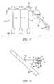
- FIG. 1is a partial longitudinal sectional view of a turbine engine high pressure compressor rotor.
- FIG. 2is an enlarged view of a balance flange of the rotor of FIG. 1 .
- FIG. 3is a partial cutaway view of a rotor hub and balance flange according to principles of the invention.
- FIG. 4is a partial cutaway view of a prior art rotor hub and balance flange.
- FIG. 5is a partial radial view of a balance flange.
- FIG. 1shows a rotor 20 of a turbine engine high pressure compressor section. From fore to aft, the rotor includes three blade disks 22 , 24 , 26 and a rear disk or hub 28 secured to each other such as by welding.
- the rotorhas a central longitudinal axis 500 which is a central longitudinal axis of the engine and an axis about which the rotor rotates.
- the periphery of each blade diskhas mounting features 30 for mounting a circumferential array or stage of blades (not shown).
- the rear hub 28has a frustoconical web 40 extending aft and radially inward from a junction with the rear blade disk 26 to a flange 42 for mounting to a high spool shaft (not shown).
- the rear hub 28has a balance flange 50 extending generally longitudinally aft from the web 40 .
- the exemplary flangehas inboard and outboard surfaces 52 and 54 and extends from a relatively thick root 56 at the web 40 to an aft rim 58 .
- a relatively thin distal or aft mounting portion 60extends to the rim 58 and is provided with mounting apertures (discussed below) for the securing of weights 62 by means of fasteners 64 (e.g., rivets or threaded fasteners).
- the flange inboard surface 52has a smooth continuously curving transition to the outboard/aft surface of the web 40 and smoothly extends to a distal longitudinal portion along the mounting portion 60 .
- the flange outboard surface 54has a shoulder or step 70 at the fore/proximal end of the mounting portion 60 , extending generally longitudinally fore and aft of the step.
- An intermediate portion 72extends forward from the shoulder 70 with inboard and outboard surfaces initially parallel and then transitioning as described above.
- the outboard surfacedefines a slight channel 74 which facilitates machining of the surface 54 .
- FIG. 3shows further details of the balance flange 50 with weights removed.
- the mounting aperturesare provided in pairs.
- FIG. 3shows a first pair of first and second apertures 80 A and 82 A and a second pair of first and second apertures 80 B and 82 B.
- Each of the aperturesis formed as a cylindrical radially-extending hole frustoconically beveled at the outboard surface 54 for accommodating an end (e.g., the head) of an associated one of the fasteners 64 .
- the exemplary flange rim 58has two groups of recesses 84 and 86 , extending forward from a flat broken annular portion 88 , the unbroken part of which form flats of islands between adjacent recesses).
- Each recess 84lies circumferentially between a pair of apertures for mounting a given weight.
- Each recess 86lies between two adjacent pairs.
- the recessesmay function to reduce weight and relieve hoop stress in the mounting portion 60 .
- FIG. 4shows an exemplary prior art balance flange 150 wherein analogous portions to the flange 50 are shown with like numerals incremented by one hundred.
- the flangehas a rim 158 and similar (identical in an exemplary embodiment) pairs of mounting apertures 180 A, 182 A, 180 B, 182 B.
- the flangeonly has recesses 186 between adjacent aperture pairs and not between apertures of a given pair. Accordingly, the rim flats of broken portion 188 are of greater circumferential extent than those of the flange 50 . Additionally, the recesses 186 are narrower than the recesses 86 . This narrowness may be measured at various longitudinal positions relative to the common plane of aperture centerlines (or intersections thereof with the projection of the flange outboard surface).
- the recesses 186have a greater amount of aft-to-fore taper and the rim broken portion 188 is more rearwardly spaced stet the apertures (e.g., the mounting portion is longer in the flange 150 than in the flange 50 ).
- the flange 150may be remanufactured in one or more ways to more closely resemble the flange 50 .
- the recesses 186may be machined to broaden them and make them more blunt.
- the rimmay be trimmed by machining to longitudinally shift the broken annular portion 188 forward.
- the second plurality of the recessescan be machined between adjacent apertures of each pair.
- FIG. 5is a view of the circumferential outboard surface 54 of the flange 50 .
- FIG. 5shows slightly more than one cycle of mounting features along the flange, specifically showing apertures 82 A, 80 B and 82 B, each having an axis 510 .
- the spacing S 2is slightly smaller than the spacing S 1 .
- the axes 510are recessed forwardly of the rim annular portion 88 by a distance S 3 .
- An exemplary recess 84has a uniform radius of curvature R 1 with a center of curvature offset rearwardly of the annular portion 88 by a distance S 4 so that a width W 1 of the recess at the annular portion 88 is slightly less than twice R 1 and a depth L 1 of the recess 84 ahead of the portion 88 is slightly less than R 1 .
- the exemplary recess 86has more complex curvature.
- a central base portion 200 of the recesshas a relatively large radius of curvature R 2 .
- Outboard aft portions 202 extending forward from the surface 88are essentially straight and longitudinal. Transition portions 204 between the portion 200 and portion 202 have a relatively small radius of curvature R 3 .
- the recess 86has a width W 2 at the surface 88 and a depth L 2 .
- the recesshas a width W 3 at the longitudinal position of the axes 510 which is relatively close to W 2 .
- the first recess depth L 1is slightly less than the second recess depth L 2 , leaving a correspondingly greater mounting portion length L 3 ahead of the first recess than L 4 ahead of the second recess.
- a flange radius along the outboard surface of the mounting portion 60is 9.58 inches, a thickness of the mounting portion is 0.131 inches, a length of the mounting portion 60 is 0.5375 inch, and there are twenty pairs of mounting apertures.
- the mounting apertureshave a nominal diameter of 0.11 inch, with a diameter at the chamfer of 0.16 inch.
- the separations S 1 , S 2 and S 3are 0.719, 0.786, and 0.117 inch.
- the longitudinal spans L 3 and L 4are 0.115 and 0.075 inch.
- the radius R 1is 0.21 inch and the separation S 4 is 0.025 inch.
- the radii R 2 and R 3are 0.575 and 0.13 inch.
- the widths W 1 , W 2 , and W 3are 0.417, 0.490, and 0.478 inch.
- the depth and breadth of the recess 86serves to reduce weight and hoop stresses at the circumferential ends of the weight mounting areas.
- the recesses 84serve primarily for weight reduction as hoop stress reduction is not as great a concern within individual weight mounting areas.
- the partial circle shape of the recesses 84reflects ease of machining (e.g., through use of simpler, less expensive, and/or more robust machining cutter and/or reduced use of the cutter). Although potentially advantageous from a weight reduction point of view, the benefits of making the recesses 84 similar to the recesses 86 might not be worth the additional manufacturing costs.
- FIG. 5further shows, in broken line, the rim 158 of the prior art flange 150 .
- the mounting apertures and shoulder of such flangeare coincident with those of the flange 50 and are not separately illustrated.
- the base of the recess 186is forward of the base of the recess 86 . Accordingly, in the manufacturing process the rim flat portion 188 may be machined down to coincident with the rim flat portion 88 and additional recesses may be machined coincident with the recesses 84 .
- the recess 186may be machined to provide a recess 86 ′.
- the recess 86 ′is broader and substantially blunter than the baseline recess 186 .
- the width at the rimmay be slightly larger than the corresponding baseline dimension W 4 (e.g., by 5-15%).
- the width between aperturesis advantageously substantially larger (e.g., by 30-80%) than the corresponding baseline dimension W 5 .
- the exemplary recess 86 ′is deeper than the recess 86 .
- the depth of the recess 86 ′is chosen to be slightly deeper than the baseline recess 186 .
- the exemplary recess 86is not so deep in order to limit manufacturing costs. Although potentially advantageous, the benefits of making the recesses 86 similar to the recesses 86 ′ might not be worth the additional manufacturing costs.
Landscapes
- Engineering & Computer Science (AREA)
- Mechanical Engineering (AREA)
- General Engineering & Computer Science (AREA)
- Physics & Mathematics (AREA)
- Acoustics & Sound (AREA)
- Aviation & Aerospace Engineering (AREA)
- Turbine Rotor Nozzle Sealing (AREA)
- Structures Of Non-Positive Displacement Pumps (AREA)
- Control Of Turbines (AREA)
- Secondary Cells (AREA)
Abstract
Description
Claims (21)
Priority Applications (6)
| Application Number | Priority Date | Filing Date | Title |
|---|---|---|---|
| US10/361,364US6893222B2 (en) | 2003-02-10 | 2003-02-10 | Turbine balancing |
| EP04250695AEP1445422B1 (en) | 2003-02-10 | 2004-02-10 | Turbine balancing |
| JP2004033046AJP3944489B2 (en) | 2003-02-10 | 2004-02-10 | Turbine engine disc and method for regenerating turbine disc |
| AT04250695TATE494456T1 (en) | 2003-02-10 | 2004-02-10 | BALANCING THE TURBINE |
| EP10009970.4AEP2264280B1 (en) | 2003-02-10 | 2004-02-10 | Turbine balancing |
| DE602004030839TDE602004030839D1 (en) | 2003-02-10 | 2004-02-10 | Balancing the turbine |
Applications Claiming Priority (1)
| Application Number | Priority Date | Filing Date | Title |
|---|---|---|---|
| US10/361,364US6893222B2 (en) | 2003-02-10 | 2003-02-10 | Turbine balancing |
Publications (2)
| Publication Number | Publication Date |
|---|---|
| US20040156708A1 US20040156708A1 (en) | 2004-08-12 |
| US6893222B2true US6893222B2 (en) | 2005-05-17 |
Family
ID=32655668
Family Applications (1)
| Application Number | Title | Priority Date | Filing Date |
|---|---|---|---|
| US10/361,364Expired - LifetimeUS6893222B2 (en) | 2003-02-10 | 2003-02-10 | Turbine balancing |
Country Status (5)
| Country | Link |
|---|---|
| US (1) | US6893222B2 (en) |
| EP (2) | EP1445422B1 (en) |
| JP (1) | JP3944489B2 (en) |
| AT (1) | ATE494456T1 (en) |
| DE (1) | DE602004030839D1 (en) |
Cited By (25)
| Publication number | Priority date | Publication date | Assignee | Title |
|---|---|---|---|---|
| US20060133938A1 (en)* | 2004-12-18 | 2006-06-22 | Stuart Ellis | Balancing method |
| US20070059164A1 (en)* | 2005-04-29 | 2007-03-15 | Snecma | Turbine module for a gas turbine engine |
| US20090025461A1 (en)* | 2007-07-25 | 2009-01-29 | Cameron Todd Walters | Method of balancing a gas turbine engine rotor |
| US20090304509A1 (en)* | 2006-10-24 | 2009-12-10 | Snecma | Balancing system for turbomachine rotor |
| US20110027085A1 (en)* | 2009-07-30 | 2011-02-03 | Glasspoole David F | Axial balancing clip weight for rotor assembly and method for balancing a rotor assembly |
| US20110044816A1 (en)* | 2009-08-19 | 2011-02-24 | Joseph Daniel Lecuyer | Balancing apparatus for rotor assembly |
| US20110078901A1 (en)* | 2009-10-01 | 2011-04-07 | Glasspoole David F | Radial balancing clip weight for rotor assembly |
| US20110097206A1 (en)* | 2008-05-29 | 2011-04-28 | Snecma | Annular flange for fastening a rotor or stator element |
| US20110274541A1 (en)* | 2008-11-07 | 2011-11-10 | Snecma | Annular flange for fastening a rotor or stator element in a turbomachine |
| US20120121437A1 (en)* | 2010-11-15 | 2012-05-17 | Mtu Aero Engines Gmbh | Rotor for a turbo machine |
| WO2013138023A1 (en) | 2012-03-12 | 2013-09-19 | United Technologies Corporation | Turbomachine rotor balancing system |
| RU2520807C2 (en)* | 2009-03-06 | 2014-06-27 | Снекма | Device for repair of aircraft engine crankcase flange, aircraft engine module, aircraft engine and method of repair of aircraft engine crankcase flange |
| US8984940B2 (en) | 2012-04-04 | 2015-03-24 | Elliot Company | Passive dynamic inertial rotor balance system for turbomachinery |
| US9169730B2 (en) | 2011-11-16 | 2015-10-27 | Pratt & Whitney Canada Corp. | Fan hub design |
| RU2650237C2 (en)* | 2012-07-17 | 2018-04-11 | Соулар Тёрбинз Инкорпорейтед | First stage compressor disc configured for balancing the compressor rotor assembly |
| US20180313367A1 (en)* | 2017-04-28 | 2018-11-01 | Rolls-Royce Deutschland Ltd & Co Kg | Rotor arrangement with balancing element and method for mounting a balancing element |
| US20180320601A1 (en)* | 2017-05-04 | 2018-11-08 | Rolls-Royce Corporation | Turbine assembly with auxiliary wheel |
| EP3502415A1 (en) | 2017-12-14 | 2019-06-26 | United Technologies Corporation | Rotor, corresponding gas turbine engine and method of assembling said rotor |
| US20190284936A1 (en)* | 2018-03-15 | 2019-09-19 | United Technologies Corporation | Gas turbine engine rotor disk |
| US10774678B2 (en) | 2017-05-04 | 2020-09-15 | Rolls-Royce Corporation | Turbine assembly with auxiliary wheel |
| US10865646B2 (en) | 2017-05-04 | 2020-12-15 | Rolls-Royce Corporation | Turbine assembly with auxiliary wheel |
| US10968744B2 (en) | 2017-05-04 | 2021-04-06 | Rolls-Royce Corporation | Turbine rotor assembly having a retaining collar for a bayonet mount |
| EP3809022A1 (en) | 2019-10-18 | 2021-04-21 | Raytheon Technologies Corporation | Balanced circumferential seal |
| US20220243593A1 (en)* | 2021-02-02 | 2022-08-04 | Pratt & Whitney Canada Corp. | Rotor balance assembly |
| US20250052158A1 (en)* | 2023-08-08 | 2025-02-13 | Rolls-Royce North American Technologies Inc. | Rotor assembly for gas turbine engines with replaceable balance weight bands |
Families Citing this family (14)
| Publication number | Priority date | Publication date | Assignee | Title |
|---|---|---|---|---|
| JP4685801B2 (en)* | 2005-01-21 | 2011-05-18 | 株式会社日立製作所 | Gas turbine balance correction method |
| FR2885196B1 (en)* | 2005-04-29 | 2007-06-29 | Snecma Moteurs Sa | DEVICE FOR BALANCING A TURBOMACHINE ROTOR |
| FR2939470B1 (en)* | 2008-12-10 | 2011-01-07 | Snecma | BLOWER FOR TURBOMACHINE COMPRISING A BALANCING SYSTEM HAVING MOUNTED HOUSING HOUSES |
| DE102009014846B4 (en)* | 2009-03-30 | 2018-10-04 | Rolls-Royce Deutschland Ltd & Co Kg | Rotor for a turbomachine, in particular for a gas turbine engine, which has recesses in a mounting flange material removal webs for balancing the rotor |
| US8794911B2 (en)* | 2010-03-30 | 2014-08-05 | United Technologies Corporation | Anti-rotation slot for turbine vane |
| US8888442B2 (en)* | 2012-01-30 | 2014-11-18 | Pratt & Whitney Canada Corp. | Stress relieving slots for turbine vane ring |
| FR2999227B1 (en)* | 2012-12-10 | 2015-02-06 | Snecma | METHOD FOR BALANCING A TURBOMACHINE ROTOR AND BALANCED ROTOR BY SUCH A METHOD |
| FR3001515B1 (en)* | 2013-01-25 | 2015-03-20 | Snecma | ASSEMBLY OF BALANCING MASSELOTTE TO A ROTOR ELEMENT |
| FR3021066B1 (en)* | 2014-05-19 | 2019-05-10 | Safran Aircraft Engines | BALANCED ROTOR DISC, AND BALANCING METHOD |
| EP3091179B1 (en)* | 2015-05-07 | 2021-06-30 | MTU Aero Engines AG | Rotor assembly for a fluid flow engine and compressor |
| US10364688B2 (en)* | 2016-11-04 | 2019-07-30 | United Technologies Corporation | Minidisk balance flange |
| US20180320522A1 (en)* | 2017-05-04 | 2018-11-08 | Rolls-Royce Corporation | Turbine assembly with auxiliary wheel |
| DE102018207432A1 (en)* | 2018-05-14 | 2019-11-28 | Volkswagen Aktiengesellschaft | Carrier with balancing weights |
| US12173612B2 (en)* | 2023-02-22 | 2024-12-24 | Solar Turbines Incorporated | Power turbine shaft with hub assembly for gas turbine engine |
Citations (4)
| Publication number | Priority date | Publication date | Assignee | Title |
|---|---|---|---|---|
| US4220055A (en)* | 1977-09-23 | 1980-09-02 | Societe Nationale D'etude Et De Construction De Moteurs D'aviation | Device to balance a rotor |
| US4270259A (en)* | 1979-03-15 | 1981-06-02 | Thexton Manufacturing Company | Method and apparatus for rebuilding advance weights |
| US4803893A (en)* | 1987-09-24 | 1989-02-14 | United Technologies Corporation | High speed rotor balance system |
| US5369882A (en)* | 1992-02-03 | 1994-12-06 | General Electric Company | Turbine blade damper |
Family Cites Families (95)
| Publication number | Priority date | Publication date | Assignee | Title |
|---|---|---|---|---|
| US3124136A (en)* | 1964-03-10 | Method of repairing body tissue | ||
| US1179910A (en)* | 1914-04-15 | 1916-04-18 | Edwin J Greenfield | Surgical saw. |
| US2113246A (en)* | 1937-05-17 | 1938-04-05 | Wappler Frederick Charles | Endoscopic forceps |
| US2666430A (en)* | 1949-05-31 | 1954-01-19 | Gispert Humberto Altamirano | Hip nail aiming and guiding device |
| US2671444A (en)* | 1951-12-08 | 1954-03-09 | Jr Benjamin F Pease | Nonmetallic mesh surgical insert for hernia repair |
| US2738790A (en)* | 1954-08-12 | 1956-03-20 | George P Pilling & Son Company | Suturing instrument |
| US3364200A (en)* | 1960-03-28 | 1968-01-16 | Johnson & Johnson | Oxidized cellulose product and method for preparing the same |
| US3551987A (en)* | 1968-09-12 | 1971-01-05 | Jack E Wilkinson | Stapling clamp for gastrointestinal surgery |
| US3710592A (en)* | 1970-07-30 | 1973-01-16 | I Scow | Crocheting apparatus |
| US4006747A (en)* | 1975-04-23 | 1977-02-08 | Ethicon, Inc. | Surgical method |
| US4193137A (en)* | 1977-05-06 | 1980-03-18 | Meadox Medicals, Inc. | Warp-knitted double-velour prosthesis |
| US4371124A (en)* | 1979-10-18 | 1983-02-01 | Brunswick Corporation | Drag system for spinning style fishing reel |
| US4576167A (en)* | 1981-09-03 | 1986-03-18 | United States Surgical Corporation | Surgical stapler apparatus with curved shaft |
| US4438769A (en)* | 1982-04-15 | 1984-03-27 | Pratt Clyde R | Medical staple device |
| US4911165A (en)* | 1983-01-12 | 1990-03-27 | Ethicon, Inc. | Pliabilized polypropylene surgical filaments |
| US4997434A (en)* | 1983-02-16 | 1991-03-05 | Seedhom Bahaa B | Prosthetic ligaments and instruments for use in the surgical replacement of ligaments |
| US4905692A (en)* | 1984-01-10 | 1990-03-06 | K. T. Medical, Inc. | Medical and orthopedic support fabric |
| JPH0698143B2 (en)* | 1984-06-18 | 1994-12-07 | オリンパス光学工業株式会社 | Tool for collecting foreign matter in body cavity |
| US4569469A (en)* | 1985-02-15 | 1986-02-11 | Minnesota Mining And Manufacturing Company | Bone stapler cartridge |
| US4652264A (en)* | 1985-04-25 | 1987-03-24 | American Cyanamid Company | Prosthetic tubular article |
| US4635634A (en)* | 1985-07-12 | 1987-01-13 | Santos Manuel V | Surgical clip applicator system |
| US5002551A (en)* | 1985-08-22 | 1991-03-26 | Johnson & Johnson Medical, Inc. | Method and material for prevention of surgical adhesions |
| US4909789A (en)* | 1986-03-28 | 1990-03-20 | Olympus Optical Co., Ltd. | Observation assisting forceps |
| US4898156A (en)* | 1987-05-18 | 1990-02-06 | Mitek Surgical Products, Inc. | Suture anchor |
| US4899743A (en)* | 1987-12-15 | 1990-02-13 | Mitek Surgical Products, Inc. | Suture anchor installation tool |
| US4986831A (en)* | 1988-04-25 | 1991-01-22 | Angeion Corporation | Medical implant |
| CA2004658C (en)* | 1988-06-03 | 1995-10-10 | Michael A. Oberlander | Arthroscopic clip and insertion tool |
| US5080674A (en)* | 1988-09-08 | 1992-01-14 | Zimmer, Inc. | Attachment mechanism for securing an additional portion to an implant |
| FR2646343B1 (en)* | 1989-04-27 | 1991-12-20 | Gazielly Dominique | DEVICE FOR REINFORCING AND SUPPORTING THE HAIR OF THE ROTATORS OF AN INDIVIDUAL SHOULDER JOINT |
| US5002550A (en)* | 1989-06-06 | 1991-03-26 | Mitek Surgical Products, Inc. | Suture anchor installation tool |
| US5088323A (en)* | 1990-01-16 | 1992-02-18 | Ltj Enterprises, Inc. | Actuator for visual indicator |
| US4997433A (en)* | 1990-01-16 | 1991-03-05 | Marlowe Goble E | Endosteal fixation stud and system |
| US5089013A (en)* | 1990-02-01 | 1992-02-18 | Ethicon, Inc. | Suture coated with a polyvinyl ester |
| US5290294A (en)* | 1990-04-17 | 1994-03-01 | Brian Cox | Method and apparatus for removal of a foreign body cavity |
| US5084058A (en)* | 1990-04-25 | 1992-01-28 | Mitek Surgical Products, Inc. | Suture rundown tool and cutter system |
| US5087263A (en)* | 1990-04-25 | 1992-02-11 | Mitek Surgical Products, Inc. | Suture throw holder and rundown system |
| US5078731A (en)* | 1990-06-05 | 1992-01-07 | Hayhurst John O | Suture clip |
| US5180388A (en)* | 1990-06-28 | 1993-01-19 | American Cyanamid Company | Bone pinning system |
| US5100417A (en)* | 1990-07-13 | 1992-03-31 | American Cyanamid Company | Suture anchor and driver assembly |
| US5098440A (en)* | 1990-08-14 | 1992-03-24 | Cordis Corporation | Object retrieval method and apparatus |
| US5178630A (en)* | 1990-08-28 | 1993-01-12 | Meadox Medicals, Inc. | Ravel-resistant, self-supporting woven graft |
| US5156315A (en)* | 1990-09-17 | 1992-10-20 | United States Surgical Corporation | Arcuate apparatus for applying two-part surgical fasteners |
| US5725529A (en)* | 1990-09-25 | 1998-03-10 | Innovasive Devices, Inc. | Bone fastener |
| US5085661A (en)* | 1990-10-29 | 1992-02-04 | Gerald Moss | Surgical fastener implantation device |
| US5078730A (en)* | 1990-11-06 | 1992-01-07 | Mitek Surgical Products, Inc. | Holder for suture anchor assembly |
| JP2902140B2 (en)* | 1991-03-15 | 1999-06-07 | 三菱重工業株式会社 | Rotating body counterweight device |
| EP0525791A1 (en)* | 1991-08-02 | 1993-02-03 | DeMatteis, Ralph A. | Method and apparatus for laparoscopic repair of hernias |
| US5197968A (en)* | 1991-08-14 | 1993-03-30 | Mectra Labs, Inc. | Disposable tissue retrieval assembly |
| US5290217A (en)* | 1991-10-10 | 1994-03-01 | Earl K. Sipes | Method and apparatus for hernia repair |
| US5289963A (en)* | 1991-10-18 | 1994-03-01 | United States Surgical Corporation | Apparatus and method for applying surgical staples to attach an object to body tissue |
| US5292328A (en)* | 1991-10-18 | 1994-03-08 | United States Surgical Corporation | Polypropylene multifilament warp knitted mesh and its use in surgery |
| CA2181674A1 (en)* | 1991-12-03 | 1993-10-04 | Theodore V. Benderev | Support structure for supporting and positioning medical equipment |
| US5176692A (en)* | 1991-12-09 | 1993-01-05 | Wilk Peter J | Method and surgical instrument for repairing hernia |
| US5192008A (en)* | 1992-01-23 | 1993-03-09 | Dai Shyun Enterprise Co., Ltd. | Pulling mechanism of an adhesive-dispensing gun |
| US5188636A (en)* | 1992-05-07 | 1993-02-23 | Ethicon, Inc. | Purse string suture instrument |
| US5250053A (en)* | 1992-05-29 | 1993-10-05 | Linvatec Corporation | Suture shuttle device |
| US5383928A (en)* | 1992-06-10 | 1995-01-24 | Emory University | Stent sheath for local drug delivery |
| US5281237A (en)* | 1992-09-25 | 1994-01-25 | Gimpelson Richard J | Surgical stitching device and method of use |
| US5381943A (en)* | 1992-10-09 | 1995-01-17 | Ethicon, Inc. | Endoscopic surgical stapling instrument with pivotable and rotatable staple cartridge |
| US5972000A (en)* | 1992-11-13 | 1999-10-26 | Influence Medical Technologies, Ltd. | Non-linear anchor inserter device and bone anchors |
| US5868789A (en)* | 1997-02-03 | 1999-02-09 | Huebner; Randall J. | Removable suture anchor apparatus |
| US5372604A (en)* | 1993-06-18 | 1994-12-13 | Linvatec Corporation | Suture anchor for soft tissue fixation |
| US5397332A (en)* | 1993-09-02 | 1995-03-14 | Ethicon, Inc. | Surgical mesh applicator |
| US5540718A (en)* | 1993-09-20 | 1996-07-30 | Bartlett; Edwin C. | Apparatus and method for anchoring sutures |
| US5464425A (en)* | 1994-02-23 | 1995-11-07 | Orthopaedic Biosystems, Ltd. | Medullary suture anchor |
| AU1999995A (en)* | 1994-04-08 | 1995-11-10 | Atrix Laboratories, Inc. | An adjunctive polymer system for use with medical device |
| US5601575A (en)* | 1994-09-02 | 1997-02-11 | Ethicon Endo-Surgery, Inc. | Needle driving device |
| US5501690A (en)* | 1994-09-02 | 1996-03-26 | Ethicon Endo-Surgery | Suturing device |
| US5716358A (en)* | 1994-12-02 | 1998-02-10 | Johnson & Johnson Professional, Inc. | Directional bone fixation device |
| US5499991A (en)* | 1994-12-19 | 1996-03-19 | Linvatec Corporation | Endoscopic needle with suture retriever |
| US5607432A (en)* | 1995-01-23 | 1997-03-04 | Linvatec Corporation | Threaded suture anchor retriever |
| US5591207A (en)* | 1995-03-30 | 1997-01-07 | Linvatec Corporation | Driving system for inserting threaded suture anchors |
| US5733337A (en)* | 1995-04-07 | 1998-03-31 | Organogenesis, Inc. | Tissue repair fabric |
| US6042583A (en)* | 1995-06-14 | 2000-03-28 | Medworks Corporation | Bone anchor-insertion tool and surgical method employing same |
| US5591163A (en)* | 1995-06-14 | 1997-01-07 | Incont, Inc. | Apparatus and method for laparoscopic urethropexy |
| AU6329598A (en)* | 1997-02-13 | 1998-09-08 | Boston Scientific Ireland Limited, Barbados Head Office | Stabilization sling for use in minimally invasive pelvic surgery |
| US6039686A (en)* | 1997-03-18 | 2000-03-21 | Kovac; S. Robert | System and a method for the long term cure of recurrent urinary female incontinence |
| US6200261B1 (en)* | 1998-03-04 | 2001-03-13 | American Medical Systems, Inc. | Valve and methods for urinary control |
| US6382214B1 (en)* | 1998-04-24 | 2002-05-07 | American Medical Systems, Inc. | Methods and apparatus for correction of urinary and gynecological pathologies including treatment of male incontinence and female cystocele |
| PL186960B1 (en)* | 1998-05-04 | 2004-04-30 | Adamed Sp Z Oo | Intravaginal set and therapeutic method employing that set |
| US6517566B1 (en)* | 1998-05-11 | 2003-02-11 | Surgical Connections, Inc. | Devices and methods for treating e.g. urinary stress incontinence |
| US6030337A (en)* | 1998-07-30 | 2000-02-29 | American Medical Systems, Inc. | Continence augmentor and methods for urinary control |
| US6010447A (en)* | 1998-07-31 | 2000-01-04 | Kardjian; Paul M. | Bladder sling |
| US6042536A (en)* | 1998-08-13 | 2000-03-28 | Contimed, Inc. | Bladder sling |
| US6168801B1 (en)* | 1998-09-09 | 2001-01-02 | Cardiac Pacemakers, Inc. | Controlled release drug delivery |
| US6030393A (en)* | 1998-09-15 | 2000-02-29 | Corlew; Earvin L. | Needle and procedure for relieving urinary incontinence |
| US6200330B1 (en)* | 1998-11-23 | 2001-03-13 | Theodore V. Benderev | Systems for securing sutures, grafts and soft tissue to bone and periosteum |
| US7121997B2 (en)* | 1999-06-09 | 2006-10-17 | Ethicon, Inc. | Surgical instrument and method for treating female urinary incontinence |
| US6355065B1 (en)* | 1999-09-01 | 2002-03-12 | Shlomo Gabbay | Implantable support apparatus and method of using same |
| US6592515B2 (en)* | 2000-09-07 | 2003-07-15 | Ams Research Corporation | Implantable article and method |
| FR2814939B1 (en)* | 2000-10-05 | 2002-12-20 | Sofradim Production | SUB-URETRAL SUPPORT KIT FOR THE TREATMENT OF URINARY INCONTINENCE OF FEMALE EXERCISE |
| US6612977B2 (en)* | 2001-01-23 | 2003-09-02 | American Medical Systems Inc. | Sling delivery system and method of use |
| US20020147382A1 (en)* | 2001-01-23 | 2002-10-10 | Neisz Johann J. | Surgical articles and methods |
| DE60223502T2 (en)* | 2001-03-09 | 2008-11-13 | Boston Scientific Ltd., St. Michael | MEDICAL SLING |
| US6755781B2 (en)* | 2001-07-27 | 2004-06-29 | Scimed Life Systems, Inc. | Medical slings |
- 2003
- 2003-02-10USUS10/361,364patent/US6893222B2/ennot_activeExpired - Lifetime
- 2004
- 2004-02-10EPEP04250695Apatent/EP1445422B1/ennot_activeExpired - Lifetime
- 2004-02-10JPJP2004033046Apatent/JP3944489B2/ennot_activeExpired - Lifetime
- 2004-02-10ATAT04250695Tpatent/ATE494456T1/ennot_activeIP Right Cessation
- 2004-02-10DEDE602004030839Tpatent/DE602004030839D1/ennot_activeExpired - Lifetime
- 2004-02-10EPEP10009970.4Apatent/EP2264280B1/ennot_activeExpired - Lifetime
Patent Citations (4)
| Publication number | Priority date | Publication date | Assignee | Title |
|---|---|---|---|---|
| US4220055A (en)* | 1977-09-23 | 1980-09-02 | Societe Nationale D'etude Et De Construction De Moteurs D'aviation | Device to balance a rotor |
| US4270259A (en)* | 1979-03-15 | 1981-06-02 | Thexton Manufacturing Company | Method and apparatus for rebuilding advance weights |
| US4803893A (en)* | 1987-09-24 | 1989-02-14 | United Technologies Corporation | High speed rotor balance system |
| US5369882A (en)* | 1992-02-03 | 1994-12-06 | General Electric Company | Turbine blade damper |
Cited By (43)
| Publication number | Priority date | Publication date | Assignee | Title |
|---|---|---|---|---|
| US7309211B2 (en)* | 2004-12-18 | 2007-12-18 | Rolls-Royce Plc | Balancing method |
| US20060133938A1 (en)* | 2004-12-18 | 2006-06-22 | Stuart Ellis | Balancing method |
| US20070059164A1 (en)* | 2005-04-29 | 2007-03-15 | Snecma | Turbine module for a gas turbine engine |
| US7364402B2 (en)* | 2005-04-29 | 2008-04-29 | Snecma | Turbine module for a gas turbine engine |
| US8025483B2 (en)* | 2006-10-24 | 2011-09-27 | Snecma | Balancing system for turbomachine rotor |
| US20090304509A1 (en)* | 2006-10-24 | 2009-12-10 | Snecma | Balancing system for turbomachine rotor |
| US7912587B2 (en)* | 2007-07-25 | 2011-03-22 | Pratt & Whitney Canada Corp. | Method of balancing a gas turbine engine rotor |
| US20090025461A1 (en)* | 2007-07-25 | 2009-01-29 | Cameron Todd Walters | Method of balancing a gas turbine engine rotor |
| US20110097206A1 (en)* | 2008-05-29 | 2011-04-28 | Snecma | Annular flange for fastening a rotor or stator element |
| US9039351B2 (en)* | 2008-05-29 | 2015-05-26 | Snecma | Annular flange for fastening a rotor or stator element |
| US20110274541A1 (en)* | 2008-11-07 | 2011-11-10 | Snecma | Annular flange for fastening a rotor or stator element in a turbomachine |
| US8727719B2 (en)* | 2008-11-07 | 2014-05-20 | Snecma | Annular flange for fastening a rotor or stator element in a turbomachine |
| RU2520807C2 (en)* | 2009-03-06 | 2014-06-27 | Снекма | Device for repair of aircraft engine crankcase flange, aircraft engine module, aircraft engine and method of repair of aircraft engine crankcase flange |
| US20110027085A1 (en)* | 2009-07-30 | 2011-02-03 | Glasspoole David F | Axial balancing clip weight for rotor assembly and method for balancing a rotor assembly |
| US8353670B2 (en) | 2009-07-30 | 2013-01-15 | Pratt & Whitney Canada Corp. | Axial balancing clip weight for rotor assembly and method for balancing a rotor assembly |
| US20110044816A1 (en)* | 2009-08-19 | 2011-02-24 | Joseph Daniel Lecuyer | Balancing apparatus for rotor assembly |
| US8506253B2 (en) | 2009-08-19 | 2013-08-13 | Pratt & Whitney Canada Corp. | Balancing apparatus for rotor assembly |
| US20110078901A1 (en)* | 2009-10-01 | 2011-04-07 | Glasspoole David F | Radial balancing clip weight for rotor assembly |
| US8631578B2 (en) | 2009-10-01 | 2014-01-21 | Pratt & Whitney Canada Corp. | Radial balancing clip weight for rotor assembly |
| US8851847B2 (en)* | 2010-11-15 | 2014-10-07 | Mtu Aero Engines Gmbh | Rotor for a turbo machine |
| US20120121437A1 (en)* | 2010-11-15 | 2012-05-17 | Mtu Aero Engines Gmbh | Rotor for a turbo machine |
| US9169730B2 (en) | 2011-11-16 | 2015-10-27 | Pratt & Whitney Canada Corp. | Fan hub design |
| US9810076B2 (en) | 2011-11-16 | 2017-11-07 | Pratt & Whitney Canada Corp. | Fan hub design |
| WO2013138023A1 (en) | 2012-03-12 | 2013-09-19 | United Technologies Corporation | Turbomachine rotor balancing system |
| US8888458B2 (en) | 2012-03-12 | 2014-11-18 | United Technologies Corporation | Turbomachine rotor balancing system |
| US8984940B2 (en) | 2012-04-04 | 2015-03-24 | Elliot Company | Passive dynamic inertial rotor balance system for turbomachinery |
| RU2650237C2 (en)* | 2012-07-17 | 2018-04-11 | Соулар Тёрбинз Инкорпорейтед | First stage compressor disc configured for balancing the compressor rotor assembly |
| US20180313367A1 (en)* | 2017-04-28 | 2018-11-01 | Rolls-Royce Deutschland Ltd & Co Kg | Rotor arrangement with balancing element and method for mounting a balancing element |
| US20180320601A1 (en)* | 2017-05-04 | 2018-11-08 | Rolls-Royce Corporation | Turbine assembly with auxiliary wheel |
| US10774678B2 (en) | 2017-05-04 | 2020-09-15 | Rolls-Royce Corporation | Turbine assembly with auxiliary wheel |
| US10865646B2 (en) | 2017-05-04 | 2020-12-15 | Rolls-Royce Corporation | Turbine assembly with auxiliary wheel |
| US10968744B2 (en) | 2017-05-04 | 2021-04-06 | Rolls-Royce Corporation | Turbine rotor assembly having a retaining collar for a bayonet mount |
| EP3502415A1 (en) | 2017-12-14 | 2019-06-26 | United Technologies Corporation | Rotor, corresponding gas turbine engine and method of assembling said rotor |
| US11326454B2 (en) | 2017-12-14 | 2022-05-10 | Raytheon Technologies Corporation | Rotor balance weight system |
| US10697300B2 (en) | 2017-12-14 | 2020-06-30 | Raytheon Technologies Corporation | Rotor balance weight system |
| US20190284936A1 (en)* | 2018-03-15 | 2019-09-19 | United Technologies Corporation | Gas turbine engine rotor disk |
| EP3809022A1 (en) | 2019-10-18 | 2021-04-21 | Raytheon Technologies Corporation | Balanced circumferential seal |
| US11448081B2 (en) | 2019-10-18 | 2022-09-20 | Raytheon Technologies Corporation | Balanced circumferential seal |
| US11821321B2 (en) | 2019-10-18 | 2023-11-21 | Rtx Corporation | Balanced circumferential seal |
| US20220243593A1 (en)* | 2021-02-02 | 2022-08-04 | Pratt & Whitney Canada Corp. | Rotor balance assembly |
| US11578599B2 (en)* | 2021-02-02 | 2023-02-14 | Pratt & Whitney Canada Corp. | Rotor balance assembly |
| US20250052158A1 (en)* | 2023-08-08 | 2025-02-13 | Rolls-Royce North American Technologies Inc. | Rotor assembly for gas turbine engines with replaceable balance weight bands |
| US12305528B2 (en)* | 2023-08-08 | 2025-05-20 | Rolls-Royce North American Technologies Inc. | Rotor assembly for gas turbine engines with replaceable balance weight bands |
Also Published As
| Publication number | Publication date |
|---|---|
| US20040156708A1 (en) | 2004-08-12 |
| DE602004030839D1 (en) | 2011-02-17 |
| JP3944489B2 (en) | 2007-07-11 |
| EP1445422A3 (en) | 2006-09-06 |
| EP2264280A1 (en) | 2010-12-22 |
| EP1445422A2 (en) | 2004-08-11 |
| JP2004245220A (en) | 2004-09-02 |
| EP1445422B1 (en) | 2011-01-05 |
| ATE494456T1 (en) | 2011-01-15 |
| EP2264280B1 (en) | 2015-04-01 |
Similar Documents
| Publication | Publication Date | Title |
|---|---|---|
| US6893222B2 (en) | Turbine balancing | |
| US6354780B1 (en) | Eccentric balanced blisk | |
| US8888458B2 (en) | Turbomachine rotor balancing system | |
| US4451205A (en) | Rotor blade assembly | |
| US10570741B2 (en) | Method of balancing a gas turbine engine rotor | |
| US3985465A (en) | Turbomachine with removable stator vane | |
| US11220913B2 (en) | Gas turbine engine blades with airfoil plugs for selected tuning | |
| RU2565110C1 (en) | Turbojet low-pressure compressor last stage disc | |
| US9327341B2 (en) | Method of fabricating integrally bladed rotor and stator vane assembly | |
| US7850430B2 (en) | Turbomachine rotor blade | |
| US1890581A (en) | Blades for turbine rotors | |
| USRE33954E (en) | Rotor blade assembly | |
| US20240240564A1 (en) | Blisk | |
| US20240035385A1 (en) | Turbomachine rotor having improved vibratory behaviour | |
| WO2018075217A1 (en) | System for composite marine propellers | |
| US11346226B2 (en) | Turbocharger and turbine wheel | |
| CN217354887U (en) | Rotor blade, blade disc assembly and compressor rotor | |
| US9399921B2 (en) | Hub piloting diameter with relief cuts | |
| RU2248546C2 (en) | Method of balancing propeller | |
| US20220243593A1 (en) | Rotor balance assembly | |
| GB2428396A (en) | A method of manufacturing an article with a reference datum feature |
Legal Events
| Date | Code | Title | Description |
|---|---|---|---|
| AS | Assignment | Owner name:UNITED TECHNOLOGIES CORPORATION, CONNECTICUT Free format text:ASSIGNMENT OF ASSIGNORS INTEREST;ASSIGNOR:ALLAM, MAHDY A.;REEL/FRAME:013772/0593 Effective date:20030210 | |
| FEPP | Fee payment procedure | Free format text:PAYOR NUMBER ASSIGNED (ORIGINAL EVENT CODE: ASPN); ENTITY STATUS OF PATENT OWNER: LARGE ENTITY | |
| STCF | Information on status: patent grant | Free format text:PATENTED CASE | |
| FPAY | Fee payment | Year of fee payment:4 | |
| FPAY | Fee payment | Year of fee payment:8 | |
| FPAY | Fee payment | Year of fee payment:12 | |
| AS | Assignment | Owner name:RAYTHEON TECHNOLOGIES CORPORATION, MASSACHUSETTS Free format text:CHANGE OF NAME;ASSIGNOR:UNITED TECHNOLOGIES CORPORATION;REEL/FRAME:054062/0001 Effective date:20200403 | |
| AS | Assignment | Owner name:RAYTHEON TECHNOLOGIES CORPORATION, CONNECTICUT Free format text:CORRECTIVE ASSIGNMENT TO CORRECT THE AND REMOVE PATENT APPLICATION NUMBER 11886281 AND ADD PATENT APPLICATION NUMBER 14846874. TO CORRECT THE RECEIVING PARTY ADDRESS PREVIOUSLY RECORDED AT REEL: 054062 FRAME: 0001. ASSIGNOR(S) HEREBY CONFIRMS THE CHANGE OF ADDRESS;ASSIGNOR:UNITED TECHNOLOGIES CORPORATION;REEL/FRAME:055659/0001 Effective date:20200403 |